

Page 1

User Manual
43BTouch Screen
Document Release March 2012
Page 2

Leviton Touch Screen
Warranty
Leviton Manufacturing Co Inc. warrants this control touch screen to be free of material and workmanship
defects for a period of two years after system acceptance or 26 months after shipment, whichever comes
first. This Warranty is limited to repair or replacement of defective equipment returned Freight Pre-Paid
to Leviton Lighting & Energy Solutions Division at PO Box 2210, Tualatin, Oregon 97062, USA. User shall
call 1-800-959-6004 and request a return authorization number to mark on the outside of the returning
carton, to assure that the returned material will be properly received at Leviton. All equipment shipped
back to Leviton must be carefully and properly packaged to avoid shipping damage. Replacements or
repaired equipment will be returned to sender freight prepaid, F.O.B factory. Leviton is not responsible
for removing or replacing equipment on the job site, and will not honor charges for such work. Leviton
will not be responsible for any loss of use time or subsequent damages should any of the equipment fail
during the warranty period, but agrees only to repair or replace defective equipment returned to its plant
in Tualatin, Oregon. This warranty is void on any product that has been improperly installed, overloaded,
short circuited, abused, or altered in any manner. Neither the seller nor Leviton shall be liable for any
injury, loss or damage, direct or consequential arising out of the use of or inability to use the equipment.
This warranty does not cover lamps, ballasts, and other equipment which is supplied or warranted
directly to the user by their manufacturer. Leviton makes no warranty as to the Fitness for Purpose or
other implied Warranties.
Notice
Although the information contained within this user guide is believed to be accurate at the time of
printing, it is not guaranteed to be without fault and is subject to change without notice. Future software
releases may change the features or operation of this product. For current information contact:
Leviton Lighting & Energy Solutions Division
20497 SW Teton, Tualatin, OR 97062
Mailing Address:
PO Box 2210
Tualatin, OR 97062
Customer Service: (800)736-6682
Technical Support: (800)959-6004
Fax: (503)404-5601
Email: [email protected]
Internet: www.leviton.com
Copyright © 2012
Leviton Manufacturing Company Incorporated.
All Rights Reserved.
Page 3

User Manual
Contents
User Manual ...................................................................................................................................1
1. Introduction ...............................................................................................................................1
1.1. Features ....................................................................................................................................... 1
1.2. Specifications ............................................................................................................................... 1
1.3. Port Introduction ......................................................................................................................... 2
1.4. Dimensions .................................................................................................................................. 3
2. Installation .................................................................................................................................5
2.1. System Diagram .......................................................................................................................... 5
2.2. Hardware Installation ................................................................................................................. 7
3. Programmable Software .............................................................................................................7
3.1. Features ....................................................................................................................................... 7
3.2. Software Installation .................................................................................................................. 8
3.3. Device Driver Installation .......................................................................................................... 9
4. Programmable Software Introduction ....................................................................................... 11
4.1. Connection between Device and Programmable Software ................................................ 11
4.2. Menu Introduction .................................................................................................................... 12
4.3. Interface Introduction .............................................................................................................. 17
4.4. Component (Button, Label, Bar, Picture, Clock, Value) Setting ........................................ 18
4.4.1. Button Setting ................................................................................................................... 20
4.4.1.1. Add Button ................................................................................................................. 20
4.4.1.2. Button Property ......................................................................................................... 21
4.4.1.1. Copy Button ............................................................................................................... 30
4.4.2. Label Setting ...................................................................................................................... 33
4.4.2.1. Add Label ................................................................................................................... 33
4.4.2.2. Label Property ........................................................................................................... 34
4.4.3. Bar Setting ......................................................................................................................... 36
4.4.3.1. Add Bar ....................................................................................................................... 36
4.4.3.2. Bar Property ............................................................................................................... 37
4.4.4. Clock Setting ...................................................................................................................... 37
4.4.4.1. Add Clock ................................................................................................................... 37
Page 4

Leviton Touch Screen
4.4.5. Picture Setting ................................................................................................................... 38
4.4.5.1. Add Picture ................................................................................................................ 38
4.4.5.2. Picture Property ........................................................................................................ 39
4.4.6. Value Setting ..................................................................................................................... 41
4.4.6.1. Add Value ................................................................................................................... 41
4.4.6.2. Value Property ........................................................................................................... 42
4.5. Album Setting ............................................................................................................................ 43
4.6. Button, Picture’s IR Remote Control ...................................................................................... 45
4.7. Page Setting .............................................................................................................................. 47
4.8. Built-in Function (Special Page) Setting ................................................................................ 50
4.9. Button’s Advanced Setting ...................................................................................................... 55
4.10. Scene Setting ........................................................................................................................ 59
4.10.1. Scene Editing ................................................................................................................. 59
4.10.2. Scene Recall .................................................................................................................. 67
4.11. Schedule Setting ................................................................................................................... 68
4.12. Component Configuration .................................................................................................... 71
4.13. File Download ........................................................................................................................ 76
Page 5
User Manual
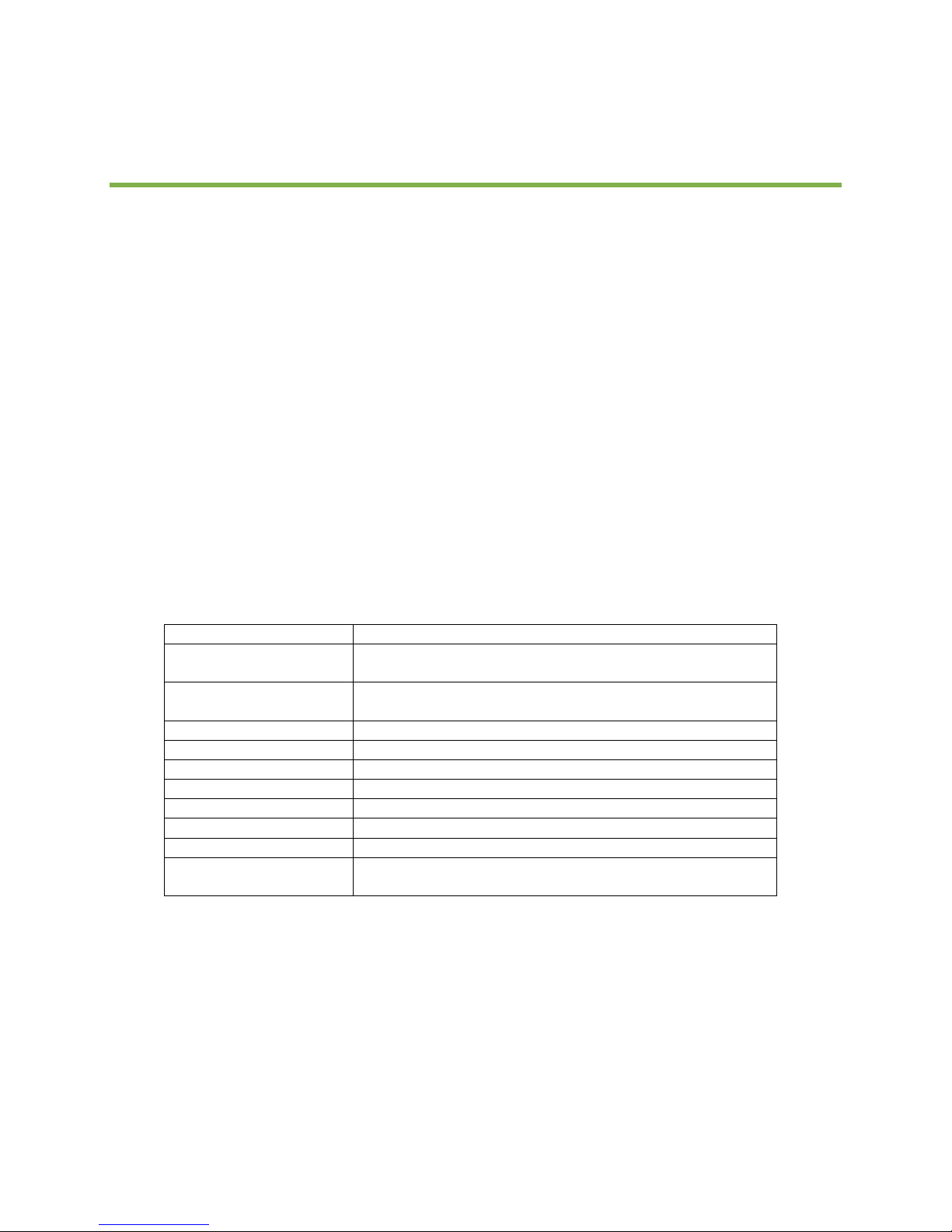
Power Supply
DC: 12V
Signal Output – EDX
EDX-485 (reference application diagrams for allowed cable
types and wiring methods.
Signal Output – DMX
DMX512/1990 (reference application diagrams for allowed
cable types and wiring methods.
Signal Connector
4 PIN green terminal
Connection Port
USB/Ethernet
RAM Memory
256MB
Screen Size
5.7 inch
Screen Resolution
320*240 pixels
Color
262K Colors
Screen
4-wire resistive touch panel
Size
8.47(W) x 5.51(H) x 1.54(D) inch
215(W) x 140(H) x 39 (D) mm
1. Introduction
Leviton’s DMX Touch Screen offers a fully flexible user interface to Leviton’s control systems.
Implementing touch screen style controls allow for a multi-page user experience specifically tailored to
your application. This product is manufactured for Leviton by Liteputer and as such you may find
references to either throughout the product documentation.
1.1. 0BFeatures
Software for designing the customized touch screen interface.
USB port or Ethernet connection, data download and remote monitoring.
Built-in functions include backlight setting, sound setting, clock setting, digital photo
frame, and password protection.
Built-in loudspeaker.
IR remote controller.
2W power consumption.
DC 12V external power.
1.2. 1BSpecifications
Rev. B
1
Page 6
Leviton Touch Screen
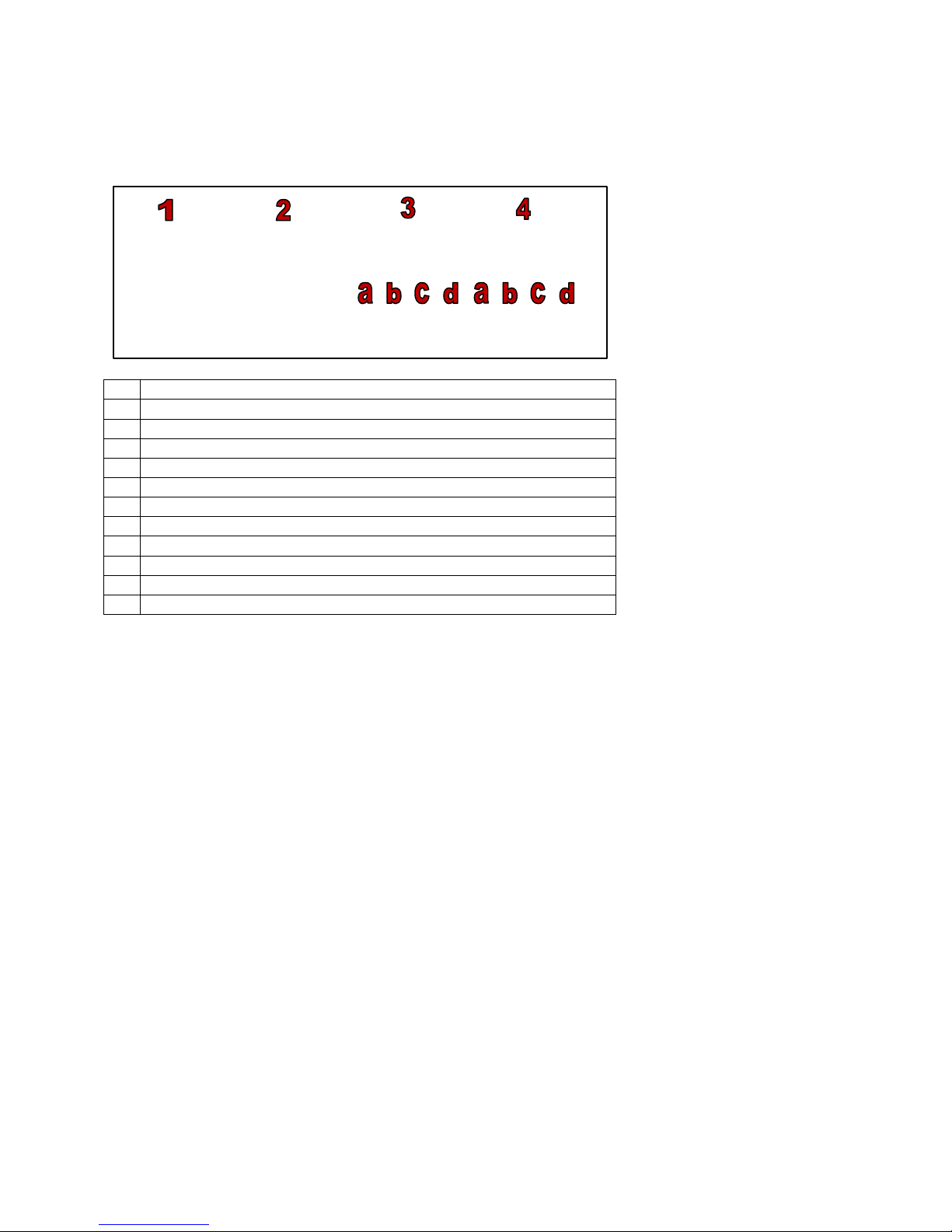
1
USB Port
2
Ethernet Port
3
EDX Port – Used for communication between touch screens
3a
Common
3b
Data -
3c
Data +
3d
+12Vdc
4
DMX Port – Used for output to dimmers
4a
Common
4b
Data -
4c
Data +
4d
+12DC
1.3. 2BPort Introduction
Page 7

User Manual
Installation
included
1.4. 3BDimensions
Back Side
back box
Rev. B
3
Page 8

Leviton Touch Screen
Front Side
Wall box
Page 9

User Manual
2. Installation
2.1. 4BSystem Diagram
The diagram below shows you one typical installation
System Example #1
This system shows multiple touch screens interconnect via EDX which is useful when you need presets to
be linked between controllers. As always, final output is via DMX to the load control devices.
Rev. B
5
Page 10

Leviton Touch Screen
System Example #2
Shown is a basic system where DMX passes through a controller. Be wary however of this style of
system as if the console is turned off, the touch-screen will not work. A better application would be the
DMX outputs from the touch screen + console being merged at the NPC or other DMX merger.
System Example #3
This shows a basic system where the touch screen is the only controller.
Page 11

User Manual
2.2. 5BHardware Installation
1. Rough In Back box
2. Terminate data wires (reference project application drawings)
3. Terminate power wires (reference project application drawings)
4. Apply power to touch-screen
5. Configure touch-screen from PC
3. Programmable Software
3.1. 6BFeatures
Page
The components in a page include button, label, bar, picture, clock and value. The style and
function of these buttons can be configured with the software.
The configurations can be transmitted from PC to the device by USB/Ethernet.
The button component can include a photo (there are photo icons available in the software). The
picture component can add a photo that the user selects and has text, shape and style options to
choose from.
Timer
50 timers.
Rev. B
7
Page 12

Leviton Touch Screen
Built-in Functions
Clock setting (can be synchronized with PC).
3 Backlight settings (normal, turn off in 5 minutes, and turn off in 20 minutes).
Voice setting (turn on/off screen tap sound).
Schedule setting/Preview function.
Password protection.
The above functions can be linked to the buttons on the page.
3.2. 7BSoftware Installation
Step-1 Copy the ECP-T04/TS005-DI5 installation program from the CD to desktop as shown
below
Step-2 Double Click the icon
Select the default language from the list.
Step-3 After language selection press Next,
Press Next again
Page 13
User Manual
Step-4 The license agreement will display, after reading, press Yes.
Continue to press Next and the software will finish installing.
Once installed a shortcut will appear on your desktop as shown below
3.3. 8BDevice Driver Installation
After the software has been installed, the next step is to install the device driver.
Step-1 After installing the software, copy the driver folder in C:\Program Files\Touch
Screen\ECP-T04\Driver\ to the desktop
Rev. B
Step-2 Connect the device to your PC using a USB cable. The below dialogue box should appear
9
Page 14

Leviton Touch Screen
Select “no, not this time”
Press Next
Select the driver folder on the desktop
Step-3 Press Next again
Step-4 Press finish and the driver is now installed
Page 15
User Manual
4. Programmable Software Introduction
4.1. 9BConnection between Device and Programmable Software
When the user opens the software the screen should look like figure 1.
Figure 1: Device is not connected
Once the device is connected the screen should look like figure 2.
Figure 2: Device is connected
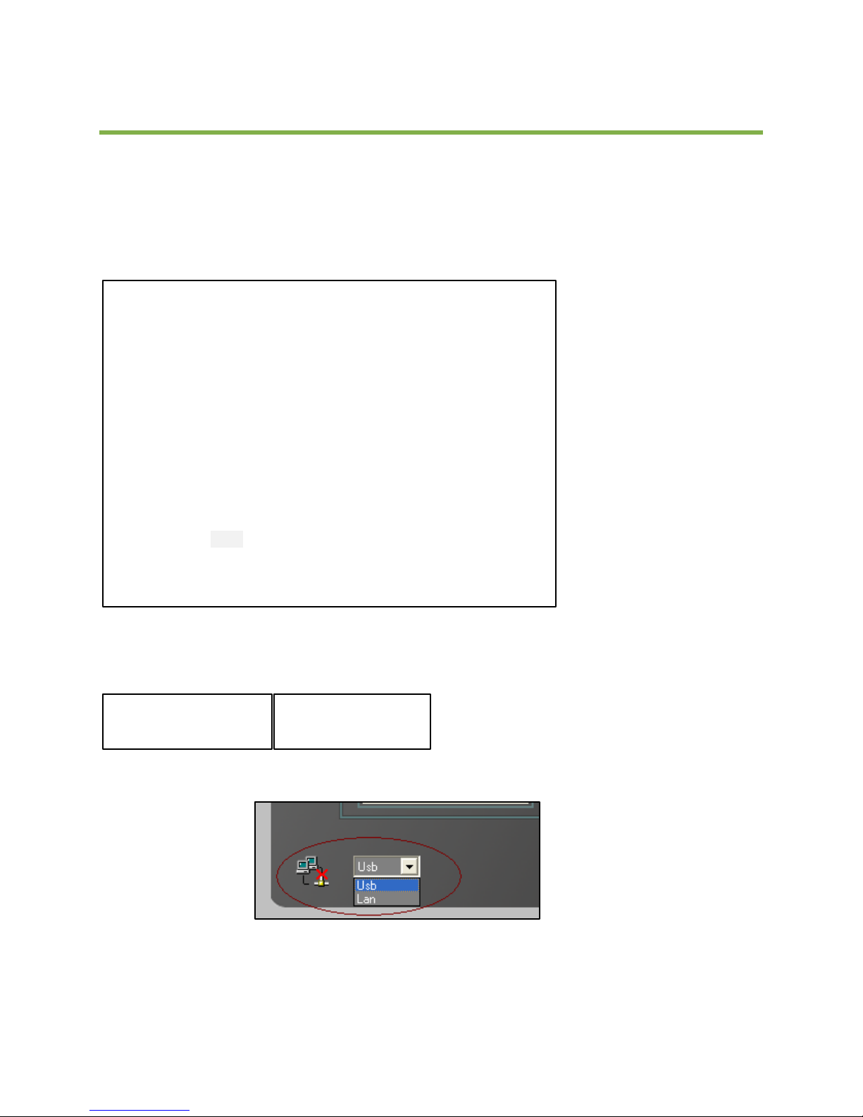
The device can be connected by USB or Ethernet, select from drop down list as shown below
22B
Rev. B
11
Page 16
Leviton Touch Screen
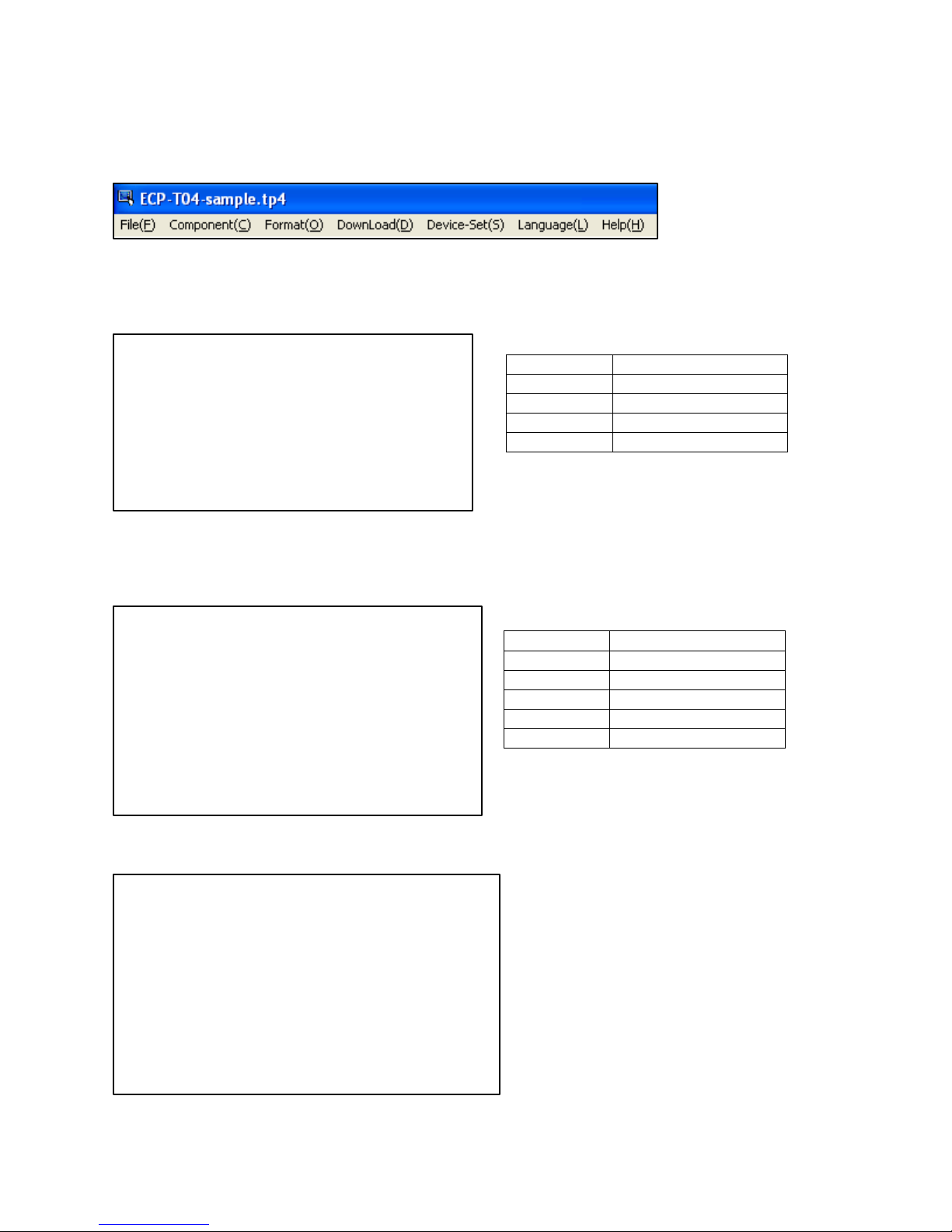
New Project
Create a new project
Open
Open a file
Save
Save a file
Save As
Save As file
Exit
Exit the program
Button
Add a button
Label
Add a label
Value
Add a value
Clock
Add a clock
Picture
Add a picture
Bar
Add a bar
4.2. 10BMenu Introduction
File menu is used to create, open and save a file
Component menu adds a button, a label, a value, a clock, a picture and a bar
Format menu modifies the components’ position, size and spacing
Page 17
User Manual
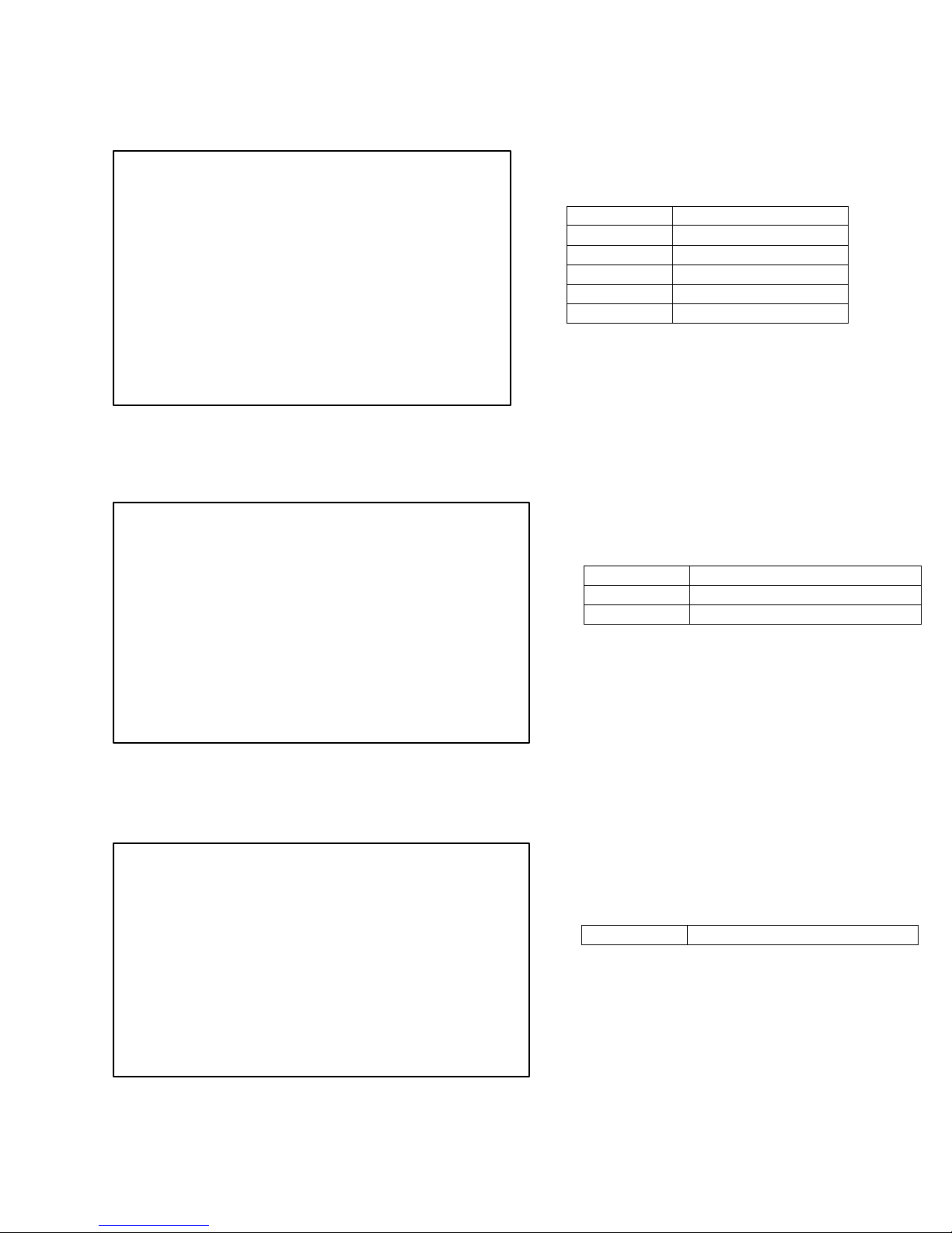
Lefts
Align Left
Centers
Align Center
Rights
Align Right
Tops
Align Top
Middles
Align Middle
Bottoms
Align Bottom
Width
Make same width
Height
Make same height
Both
Make same width and height
Make Equal
Make horizontal spacing equal
Align submenu options
Make same size submenu options
Horizontal spacing submenu options
Rev. B
13
Page 18
Leviton Touch Screen
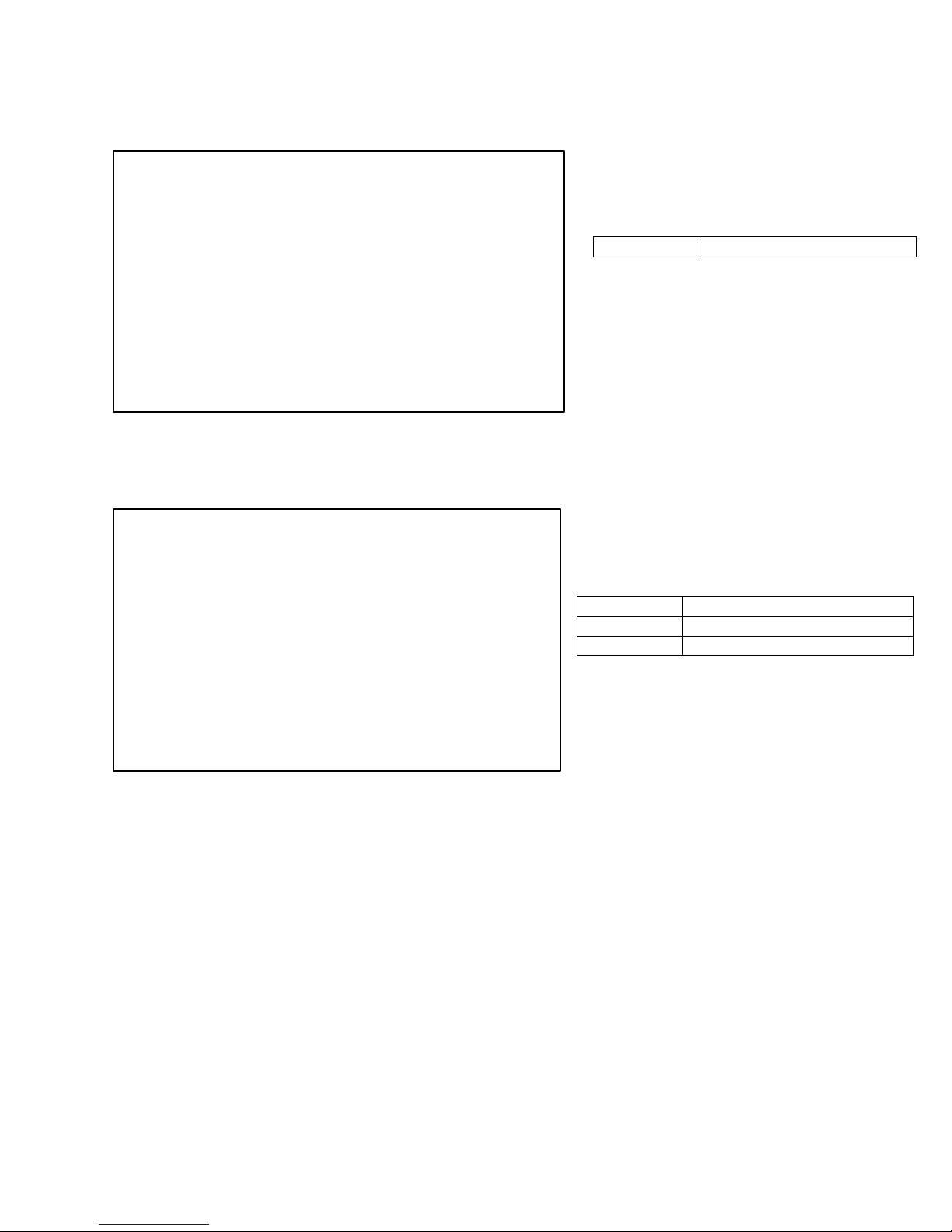
Make Equal
Make vertical spacing equal
All Page
Download all pages
Now Page
Download current page
Now Time
Download the current time
Vertical spacing submenu options
Download menu – download data from the software to the device
Device-Set Setting Includes: IP setting, device description, password setting and MAC address setting
Page 19

User Manual
Language Menu allows the user to select the preferred language. Three languages are available; English,
simplified Chinese and traditional Chinese
Help Menu
Rev. B
15
Page 20

Leviton Touch Screen
A software introduction can be found in the Help Menu.
Contacting Technical Support
If you cannot find answers in this User Manual, please contact Technical Support and we will be glad to
answer your questions.
You can also call us during regular business hours at 1-800-959-6004. Please have the model number
information available when you call.
Contact Information:
Leviton Lighting & Energy Solutions
20497 SW Teton, Tualatin, OR 97062
Mailing Address:
PO BOX 2210
Tualatin, OR 97062
Customer Service: (800) 736-6682
Technical Support: (800) 959-6004
Fax: (503) 404-5601
Email: [email protected]
Internet: www.leviton.com
Page 21
User Manual
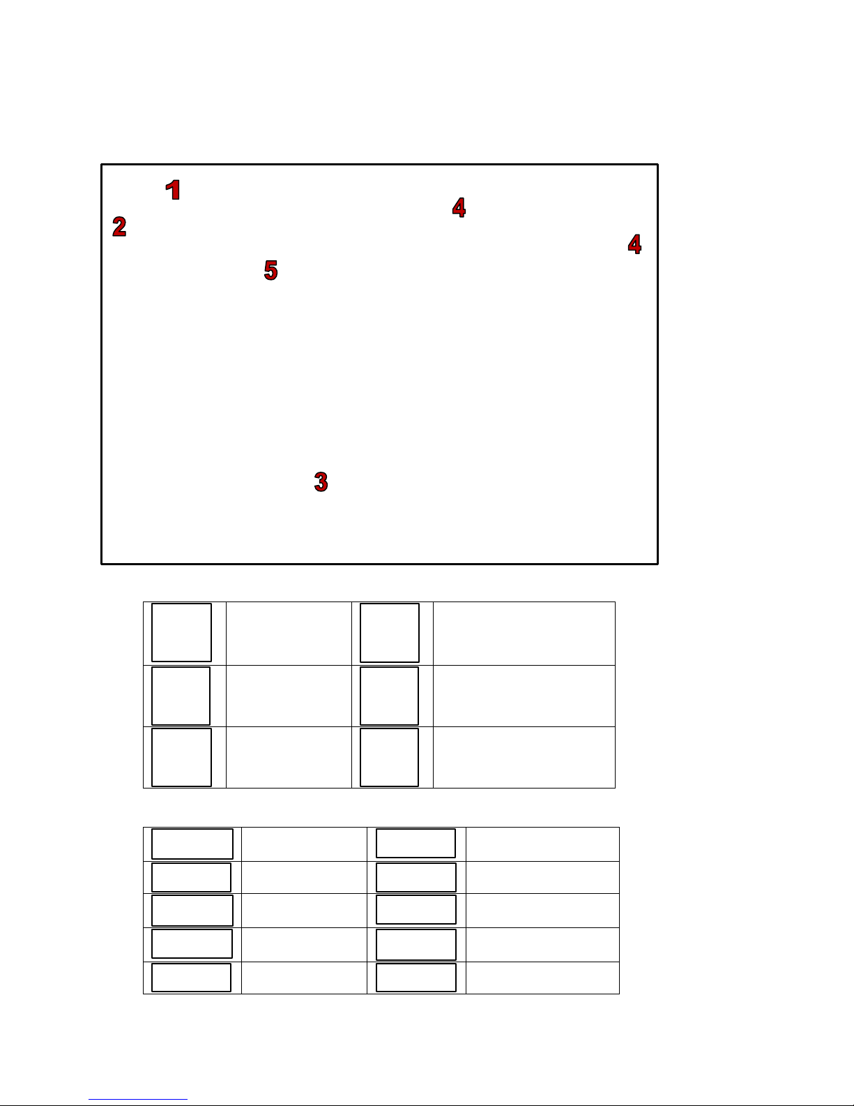
Open File
Delete Any Page
Save File
Search Device’s IP
Create New Page
Device Setting
Add Button
Add Picture
Add Label
Add Value
Add Bar
Scene Editing Button
Add Clock
Album Setting
Undo the Setting
Redo the Setting
4.3. 11BInterface Introduction
1. Interface Button Description
2. Interface Button Description
Rev. B
17
Page 22
Leviton Touch Screen
Download all Page
Data to Device
Download System Time
to Device
Download Current
Page Data to Device
Download all Data to
Device
Download Album
Photo to Device
Download Scene Data
to Device
Align Components Left
Make Components the
Same Width
Align Components
Center
Make Components the
Same Height
Align Components
Right
Make Components the
same Width and Height
Align Components Top
Horizontal Spacing Equal
Align Components
Middle
Vertical Spacing Equal
Align Components
Bottom
Select a Page
3. Interface Button Description
4. Interface Button Description
5. Displays what will show on the device screen.
4.4. 12BComponent (Button, Label, Bar, Picture, Clock, Value) Setting
Page: A page is a graphic user interface which includes components such as button, label, bar, picture,
clock and value.
Component: A graphic object displayed on a page. Components include buttons, labels, bars, values,
clock and pictures.
There are 5 types of components:
Button: The button is used to control an action, when you touch a button the programmed action takes
effect. For example a button can turn on a light or recall a scene. A button can have text and or images
programmed on it. Buttons with different functions, backgrounds, borders and styles can exist on the
same page. See button examples below.
Page 23

User Manual
Buttons can have 4 control functions: page link, scene recall, one button channel dimming value control,
two button channel dimming value control.
Page Link: Link to another page.
Scene Control: Recall the scenes of the controller.
Channel Dimming Value: 2 control methods are available-
Two buttons (up and down): increase/decrease the dimming value.
(The channel no. and zone no. are dependent on the EDX system working with the device)
One Button: directly recall a preset dimming value, for example 50%.
Label: Label is used for descriptions.
Bar: A bar can be used to adjust the channel dimming value and display the value from 0% - 100%.
Picture: The function of picture is the same as button.
Clock: Display time on the device.
Value: Display channel’s dimming value (from 0% - 100%).
Rev. B
19
Page 24

Leviton Touch Screen
4.4.1. 23BButton Setting
4.4.1.1. 31BAdd Button
Step-1 Open the software
Step-2 Press button key on the screen or use the component menu to add a button
Page 25
User Manual
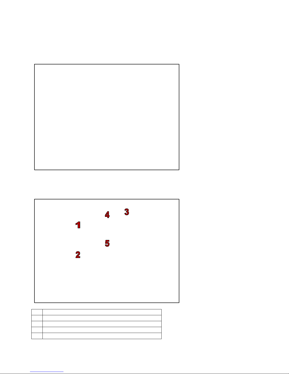
1
Text displayed when the button is inactive
2
Text displayed when the button is active
3
Align the text position
4
The color the text displays when the button is inactive
5
The color the text displays when the button is active
4.4.1.2. 32BButton Property
Step-1 After a button is added double click it to access the button property window
Text Setting
Step-2 Select the text property from the dialogue box
Rev. B
21
Page 26

Leviton Touch Screen
Step-3 Enter text into the active and inactive boxes. For example enter “ROOM ON”, into
inactive and “ROOM OFF” into active
Step-4 Use text alignment to choose text position on the button. The position chosen is
indicated by an “X”
Step-5 Press OK to save the text setting
Page 27

User Manual
Image Setting
Step-6 Double click the button and select the images tab from the property dialogue box
Rev. B
23
Page 28

Leviton Touch Screen
Step-7 Select any image below and use image alignment to choose the image’s position on the
button
Step-9 Press OK to save the image setting
Page 29
User Manual
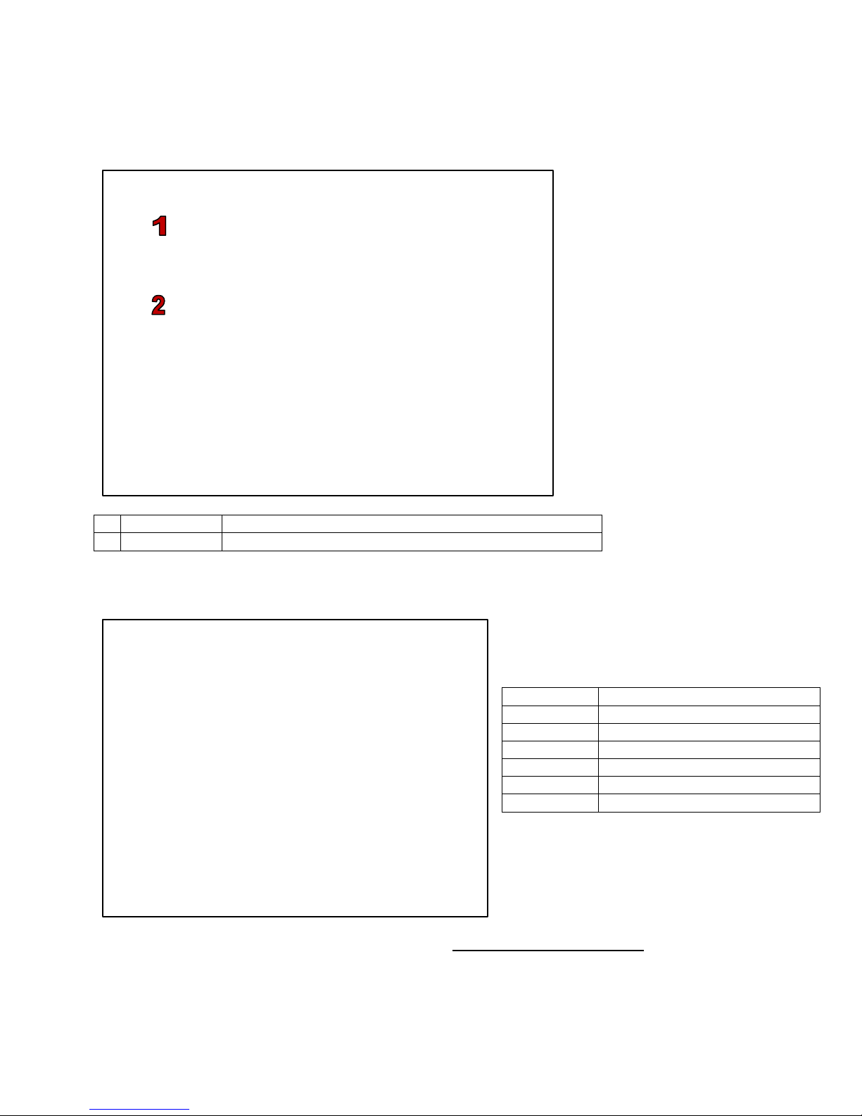
1
Key Function
Selects the function for the button
2
IR Select
Defines which key on the IR controller controls the button
Unused
Set as unused button
Page Link
Set as a page link button
Scene
Set as a scene recall button
Up/Down
Set as up/down dimmer button
Dimmer
Set as a dimmer button
On/Off
Set as a on/off button
Bell Press
Set as a bell press button
Function Setting
Step-10 Double click the button and select the function tab of the property dialogue box
Key Functions
After a function has been selected from the list, refer to 4.9 Button’s Advanced Setting for instructions on
setting the advanced settings.
Rev. B
25
Page 30
Leviton Touch Screen
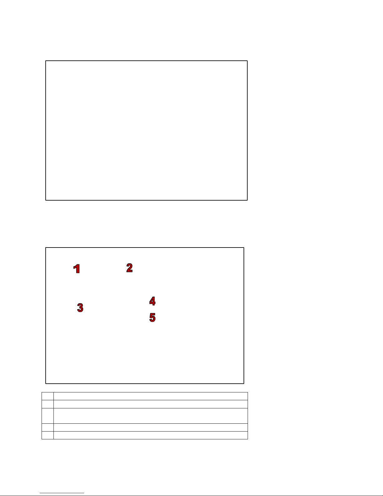
1
Position and size setting
2
Border setting
3
The button color displayed when the button has an inactive status
or active status
4
Border color setting
5
Border background setting
Step-11 For example set the button function as Page Link
Step-12 Press OK to save the function setting
Step-13 Position/Border Setting – Double click the button again and select Position/Border from
the property dialogue box
Page 31
User Manual
Border Shape options:
Rectangle
Oval
Rounded Rectangle
Note:
Left/Top – Adjusts button’s position on the illustration area.
Width/Height – Adjusts button’s width and height.
Step-14 Click into the box to the right of left/top/Width/Height to edit the number
For example: Left/top set as 0/0, width/height set as 80/60 and set the button as green when it
has a status of inactive; set the button as blue, when it is active.
Border Setting
Rev. B
27
Page 32
Leviton Touch Screen
Border Style options:
Transparent
Solid
Dash
Dot
Dash Dot
Dash-Dot-Dot
Select border width from the list
Note: Before the style selection, border width must be set at least at 1.
For example: Set the border shape as oval, border width as 6, and border style as dash.
Page 33

User Manual
Step-15 Select the drop down list for the border shape/border width/border style list to choose
the right item
Step-16 Press OK to save the position/border setting
Note: All button properties can be set at the same time and then press ok to see results.
Rev. B
29
Page 34

Leviton Touch Screen
4.4.1.1. 33BCopy Button
Copy the border shape, border color, background color and inactive, active color settings of one button to
another.
Step-1 – Add a new button to the display and set its style properties
Now there are 2 buttons on the page; Meeting Room and Cmd2
Step-2 Select Meeting Room Button and right click to select Format Copy
Page 35

User Manual
Step-3 Select cmd2 and right click to select Format Paste to copy the setting
Rev. B
31
Page 36

Leviton Touch Screen
Now double click the cmd2 button to review the property changes.
Page 37

User Manual
4.4.2. 24BLabel Setting
4.4.2.1. 34BAdd Label
Step-1 Open the software
Step-2 Press label key on the interface or use the component menu to add a label
Rev. B
33
Page 38
Leviton Touch Screen
1
Text that displays on the label
2
Aligns the text position
3
Background color setting
4
Text color setting
4.4.2.2. 35BLabel Property
Step-1 Double click the label to show the label property dialogue box
Step-2 Text setting – Select the text tab in the dialogue box
Page 39
User Manual
1
Position and size setting
2
Border setting
Border Shape options:
Rectangle
Square
Oval
Circle
Rounded Rectangle
Rounded Square
Please refer to 4.4.1.2 Button Property to finish the label’s text settings.
Step-3 Position/Border Setting -Double click the label again and select Position/Border tab of the
dialogue box
Please refer to 4.4.1.2 Button Property to finish the label’s settings.
Rev. B
35
Page 40

Leviton Touch Screen
4.4.3. 25BBar Setting
4.4.3.1. 36BAdd Bar
Step-1 Open the software
Step-2 Press the bar key on the interface or use the component menu to add a bar
Page 41
User Manual
1
Position
Where the bar will appear on the display
2
Address
Channel’s address setting (From 1 – 512)
4.4.3.2. 37BBar Property
Step-1 Double click the bar on the page
Step-2 Press OK to save the setting
4.4.4. 26BClock Setting
4.4.4.1. 38BAdd Clock
Step-1 Open the software
Rev. B
37
Page 42

Leviton Touch Screen
Step-2 Press clock key on the interface or use the component menu to add a clock
The clock can only be synchronized with the system time; time cannot be set manually.
4.4.5. 27BPicture Setting
4.4.5.1. 39BAdd Picture
Step-1 Open the software
Page 43
User Manual
1
Position
Where the picture will appear on the display and the size
2
Inactive picture path
Picture that will display when the picture is inactive
3
Active picture path
Picture that will display when the picture is active
4
Fit picture
Makes the photo the same size as the picture illustration area
5
Folder icon
Click to load picture
Step-2 Press the picture key on the interface or use the component menu to add a picture
44B
4.4.5.2. 40BPicture Property
Position/Picture Setting
Step-1 Double click the picture
Rev. B
39
Page 44
Leviton Touch Screen
1
Inactive
Text that will display when the picture is inactive
2
Text alignment
Aligns the text position
3
Font color
Text color
Text Setting
Step-2 Double click the picture and select text from the property tab in the dialogue box
Function Setting
Step-3 Double click the picture and select the function tab in the dialogue box
Step-4 Press OK to save the setting
Page 45

User Manual
4.4.6. 28BValue Setting
Value – add channel’s dimming value display (from 0% - 100%)
4.4.6.1. 41BAdd Value
Step-1 Open the software
Step-2 Press the value key on the interface or use the component menu to add a value
45B
Rev. B
41
Page 46
Leviton Touch Screen
1
Position
Value’s position setting on the display
2
Address
Channel’s DMX address setting (From 1-512)
4.4.6.2. 42BValue Property
Step-1 Double click the added value component
Step -2 Press OK to save the setting
Page 47
User Manual
1
Modify the photo’s position, move the photo to last or next frame
2
Tidy up the photo’s sequence (When photos are deleted, it will update the sequence)
4.5. 13BAlbum Setting
Album – Loads the photo to the digital photo frame. (19 photos maximum)
Step-1 Open the software
Step-2 Press Album key
The program can load 19 photos maximum, the last frame is the size display, a photo cannot be
uploaded to this slot.
Rev. B
43
Page 48
Leviton Touch Screen
3
Exit the album operation
Step-3 Double click any frame to upload the photo.
Page 49

User Manual
4.6. 14BButton, Picture’s IR Remote Control
Note: Only button and picture device components accept IR remote control. The IR remote control
setting for button and picture operate the same, the following example applies to both components.
Step-1 On the current page, press the button key on the interface or use the component menu
to add a button
Step-2 Double click the button
Rev. B
45
Page 50

Leviton Touch Screen
Step-3 Select the function tab in the property dialogue box
To set the button’s key function setting, please refer to 4.4.1.2 Button Property.
Step-4 For example, select the function as scene and choose scene 01 of zone 1 to be controlled
by this button
Step-5 Select the key on the IR remote controller corresponding to this button. For example, set
this button to the FCN key on the IR remote controller
When the FCN key is pressed on the remote controller, the device will recall scene 01 of zone 1.
Step-6 Press OK to save the setting
Note: The keys on the IR remote controller can be set to recall any function of a button.
Page 51

User Manual
IR Select – all of these options are available for the IR remote controller; None, Off, Sc1, Sc2,
Sc3, Sc4, Sc5, Sc6, Increase, Decrease, Fcn, Mem, Zone, Up, Down, Left, Right and Set.
4.7. 15BPage Setting
Page (User Page) Setting
Step-1 Open the software
Step-2 From file menu – select new project
Rev. B
47
Page 52

Leviton Touch Screen
Step-3 Press NewPg to add more pages
Step-4 From the drop down list select Page2, and then double click the display area
Page 53

User Manual
Step-5 Click the page name box and change “Page2” to “SC1”
Step-6 Press the … button to get your picture path
Rev. B
49
Page 54

Leviton Touch Screen
Step-7 Double click the picture file you want to upload
Press Clear to cancel the picture selection
Step-8 Press OK to save the setting.
4.8. 16BBuilt-in Function (Special Page) Setting
Note: User page, the notion of user page is the same as the page’s (please refer to the explanation
under 4.4 Component (Button, Label, Bar, Picture, Clock and Value Setting)
Special page: the built-in function pages can be set on the button property dialogue box. The special
page can be linked by the button component.
Built-in functions include backlight set, voice set, clock set, schedule set/preview and password
protection.
The built-in function pages available are shown below
Page 55

User Manual
Backlight Setting
Step-1 Open the software
Step-2 From the file menu – new project
Step-3 Press the button key on the interface or use the component menu to add a button
Step-4 Double click the button to access the button property dialogue box
Step-5 Select the function tab in the property dialogue box.
Rev. B
51
Page 56

Leviton Touch Screen
Step-6 Select the page link from the key function list, under page link select Special Page and
select backlight set from the page drop down list.
Page 57
User Manual
Special Page options:
Backlight set page
Voice set page
Password protection page
Clock set page
Digital Photo frame page
Schedule set page
The setting of text, images, position/border property, please refer to 4.4.1.2 Button Property. The button
can be linked to the following built in function pages.
Step-7 Press OK to save the setting
After downloading the setting to the device, the backlight set page will show by pressing the
button.
Voice Set
Step-8 Add one more button on the same page (new page), then double click the button to
access the property dialogue box
Rev. B
53
Page 58

Leviton Touch Screen
Step-9 On the function property, select the page link from the key function list, under page link
select special page and select voice set from the page list
Step-10 Press OK to save the setting
After downloading the setting to the device, the voice set page will show by pressing the button.
Note: For setting of clock set page, password protection page and schedule set page, please reference
the steps for backlight set and voice set above.
Page 59
User Manual
Unused
Set as unused button
Page Link
Set as a page link button
Scene
Set as a scene recall button
Up/Down
Set as up/down dimmer button
Dimmer
Set as a dimmer button
On/Off
Set as a on/off button
Bell Press
Set as a bell press button
4.9. 17BButton’s Advanced Setting
Button’s advanced setting is the detailed description of the 4.4.1.2 Button Property.
Double click the button and select the function tab from the property dialogue box.
Function list as below
Similar to user page and special page in 4.7 Built-in Function (Special Page) Setting user can select the
pages that link to the buttons.
Rev. B
55
Page 60

Leviton Touch Screen
By selecting key function as page link and selecting user page, the user can select the pages from the list
in the page drop down.
By selecting key function as page link and selecting special page, user can select the built-in function
pages from the list in the page drop down.
Page 61
User Manual
1
Use up or down to set the button to increase/decrease the channel’s dimming value
2
Use channel to select any channel from 1-512
Zone options:
1 – 40
Scene options:
Sc1 – Sc12 and Sc Off
By selecting key function as scene the button will recall/turn off the corresponding scene when pressed.
Select scene from key function list.
Edit Scene is where the user sets the zone and scene for the button.
By selecting key function as up/down the button will increase/decrease the corresponding channel’s
dimming value by pressing the button.
Select up/down from key function list, it will display as below
Rev. B
57
Page 62
Leviton Touch Screen
1
Channel
Select channel 1-512
2
Value
Dimming percentage
3
Fade
The fade time for the dimming percentage to be executed in
By selecting key function as dimmer the channel will be turned on at the preset dimming value when the
button is pressed; by releasing the button, the channel will be turned off.
Select dimmer from key function list
Set the zone, channel and dimming value on channel level area.
By selecting key function as on/off the button is set as a on/off button; press it once, the corresponding
channel will be turned on; press it again, the corresponding channel will be turned off. For example,
select the on/off function from the list.
Page 63

User Manual
Select the channel no. from the channel level column, and the press ok to save the setting.
By selecting key function as Bell Press the button will have the same function as an on/off button.
4.10. Scene Setting
Note: Scene settings are edited on the device directly, while page settings are edited by the software.
(Please refer to 4.1 Connection between Device and Programmable Software for downloading
instructions)
The following pages are examples of user pages.
4.10.1. 29BScene Editing
Step-1 Open the software
Rev. B
59
Page 64

Leviton Touch Screen
Step-2 Create a new page and add 6 scene buttons (name as Scene 1-5, Scene off)
Step-3 Double click the button scene 1 and select the function tab in the property dialogue box.
Set key function as scene, zone as 1 and scene as 01
Page 65
User Manual
1
The zone no. the scene belongs to. There are 40 selectable zones. (Zone 1 – Zone 40)
2
Scene no. selection (SC1 – SC12, SC off)
3
Scene editing
4
Scene copy
5
Scene paste
6
Close the scene edit dialogue box
A
Scene name editing
Step-4 Then press the Scene button on the interface
Step-5 After zone and scene no. selection press edit
Rev. B
61
Page 66
Leviton Touch Screen
B
Channel name editing
C
512 channel’s name editing area
D
Channels in scene editing area
E
Scene fade time
F
Channel’s dimming value selection (from 0%-100%)
G
Select all the channels in area D
H
Shift channels dimming value from 0% and 100%
I
Directly type in the channel’s dimming value
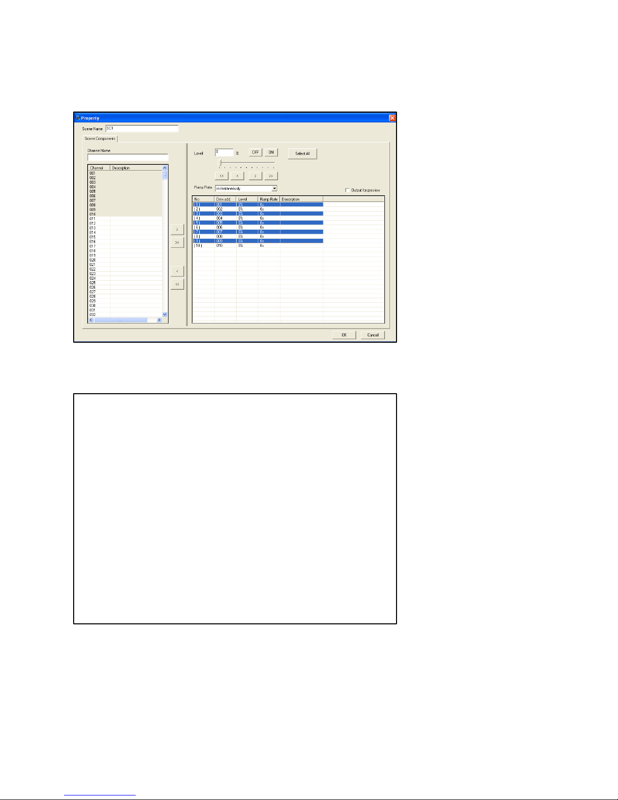
Step-6 Name the scene as SC1 and select channel 1-10 in to this scene
There are 2 methods to select any channel from the 512 channels.
Method 1: Press ctrl and click any channel from the 512 channels, for example, select the
following channels: channel 1, channel 3, channel 5, channel 7, channel 9, channel 12, channel
13, channel 15, channel 16, and channel 17.
Page 67
User Manual
1 > Load selected channels to the editing area
2
>>
Load all 512 channels to the editing area
3 < Remove the selected channels from the editing area
4
<<
Remove all channels from the editing area
Method 2: Press shift click any continuous channels from the 512 channels. For example select
channel 1 - 10
Step-7 Press > to load the selected channels 1-10 into the editing area
Rev. B
63
Page 68
Leviton Touch Screen
Step-8 Press ctrl and click the channel 1, channel 3, channel 5, channel 7, channel 9, in the
editing area
Step-9 Press level icons to adjust; channel 1, channel 3, channel 5, channel 7 and channel 9’s
dimming value to 50%.
Page 69

User Manual
Step-10 Press level icons to adjust; channel 2, channel 4, channel 6, channel 8 and channel 10’s
dimming value to 50%.
Step-11 Set the channels in SC1’s fade time using the ramp rate drop-down list
For example, set channel 1, channel 3, channel 5, channel 7 and channel 9’s fade time as 8
seconds
Press ctrl and click channel 1, channel 3, channel 5, channel 7, and channel 9 in the editing area.
Then press the ramp rate drop-down list and select over 8 seconds.
Step-12 After setting press ok to save
Rev. B
65
Page 70

Leviton Touch Screen
The setting of remaining scenes is the same.
Editing the name of a channel
Step-13 Select any channel from the 512 channel’s name editing area, it will display as below
Step-14 Type CH1 into channel name column and it will display as show below
Page 71

User Manual
Step-15 Name channel 1 to 10 as CH1 and CH10 separately and it will display as below
Step-16 After setting, press ok to save
4.10.2. 30BScene Recall
Step-1 Download edited pages to the device and press Scene 1-5 and off on the touch screen to
recall the scenes
Rev. B
67
Page 72

Leviton Touch Screen
4.11. Schedule Setting
The schedule setting is for recalling the scenes at a set time.
Step-1 Open the software
Step-2 From the file menu select new project
Step-3 Press the button/picture key on the interface or use the component menu to add a
button/picture
Step-4 Double click the button and select the function tab from the property dialogue box
Step-5 Select key function as page link, page link as special page and select schedule on the
page drop down list
To set text, image, and position/border properties please refer to 4.4.1.2 Button Property.
Page 73
User Manual
1
Activate/Deactivate schedule, yes , no
2
Go to last or next schedule set page
3
Add schedule
4
Edit schedule
5
Cancel schedule
6
Select schedule (the schedule can be edited and cancelled only after it has
been selected; if the schedule’s selected it will display as )
For example set the picture as below
Step-5 Download this page to the device and press the schedule button, it will link to the built-in
function page
Rev. B
69
Page 74
Leviton Touch Screen
7
The scene to be called on in the schedule
8
The scene’s zone to be called on in the schedule
9
The execution time of the schedule: hour and minute
1
The execution time for the schedule: hour and minute
2
The adjustment keys for hour and minute setting of the execution time
3
The execution time for the schedule: day
4
Select the scene executed on the schedule
5
Display the scene no. executed on the schedule
6
Select zone no. of the scene executed on the schedule
7
Display zone no. of the scene executed on the schedule
Step-6 Press new
Step-8 The below schedule is set to recall SC01 of Zone 1 at 1:01am on every Monday,
Wednesday and Friday
Page 75
User Manual
Step-9 After setting, press ok to save
Once the schedule is saved it can be edited and canceled. Means the schedule is activated.
Step-10 Press to exit
4.12. Component Configuration
Open the software and add 3 components, for example 3 different size buttons on the same page.
Left and right alignment:
Hold ctrl and select component cmd1, cmd2 and cmd3 then press lefts or rights to make those
components align with left or right or center.
Rev. B
71
Page 76

Leviton Touch Screen
Lefts:
Rights:
Page 77

Centers:
User Manual
Select all and align top, middle or bottom.
Tops:
Rev. B
73
Page 78

Leviton Touch Screen
Middles:
Bottoms:
Select all and make the components have the same width and height.
Note: If you want to make several components have the same width and height, you need to select the
component you want as the standard last.
Page 79

Widths:
User Manual
Heights:
Rev. B
75
Page 80
Leviton Touch Screen
Download all Page Data
to Device
Download System Time
to Device
Download Current Page
Data to Device
Download all Data to
Device
Download Album Photo to
Device
Download Scene Data to
Device
Horizontal Spacing Equal and Vertical Spacing Equal
Horizontal Spacing:
Before After
Vertical Spacing:
Before After
4.13. File Download
After the programming is completed you must download the file to the device
Choose a button below based on the type of download you want to do:
Page 81

User Manual
When the device is connected press a download button and a progress bar will display.
Download in progress Download complete
Do not use the program while the data is downloading.
To set the device’s IP
After connecting the device press search to search device’s IP.
Step-1 Open the software
Step -2 Press search on interface and the IP set window will display
Rev. B
Step-3 Press Search
77
Page 82

Leviton Touch Screen
1. IP address display area
2. Advance buttons decide whether the device information area displays.
Ok will display the information; cancel will not display the information.
3. Device information area
Step-4 Double click the information in the device information area
Step-5 Press OK to finish the connection between the device and the software
D-set button - Device Setting
Step-1 Open software
Step-2 Press D-Set
1. IP Address setting
2. Device name setting
3. Password setting
4. Mac address setting
Page 83

Copyright © 2012 Leviton Manufacturing Company Incorporated.
All Rights Reserved.
Information contained herein is subject to change without notice.
Document Release March 2012
Part # DI-000-XXXXXX
Leviton Lighting & Energy Solutions Division
20497 SW Teton, Tualatin OR 97062
Mailing Address:
PO BOX 2210
Tualatin, OR 97062
Customer Service: (800) 736-6682
Technical Support: (800) 959-6004 Fax: (503) 404-5601
Email: [email protected]
Internet: www.leviton.com
 Loading...