

Page 1
User Guide
Network Protocol Converter
Software Revision 3.10 and above
R
Page 2

User Guide
Table of Contents
Overview 3
Part 1 Initial Set-up & Basic Configuration 7
Physical Connections 8
Installation 11
System Status Check 15
Navigation & Front Panel Controls 16
Part 2 Quick Start Configuration 18
Part 3 Wrapping Up 21
Part 4 Advance Configuration & Operation 24
Main Menu 25
General Set-up 27
Device Connections 32
DMX Universe Numbers 36
Patching 38
Patch Manipulation 42
Channel Options 44
Lighting Groups 50
Event Log 53
Selecting Displays 55
Configuration by Telnet or Keyboard 57
File Transfer 60
Warranty 66
Rev: A20031222.sw3.10 Page 1
Page 3

User Guide
Figure Table of Contents
Figure 1 NPC Product Line XP, DHV and DLR 3
Figure 2 NPC Front and Back Views 8
Figure 3 Device Connections 13
Figure 4 Handheld Remote Physical Connections 14
Figure 5 Successful Status of LED 15
Figure 6 NPC Front Panel Buttons 16
Figure 7 Quickstart Device Connection Screens 19
Figure 8 Quick Start Universe Patching 20
Figure 9 NPC Main Menu 25
Figure 10 General Setup 27
Figure 11 Device Connections 33
Figure 12 DMX 512 Universes 36
Figure 13 Patching 38
Figure 14 DHV Channel Options 44
Figure 15 Typical Room with Two Partitions 50
Figure 16 Grouping of Control Channels 51
Figure 17 Lighting Groups 52
Figure 18 Event Log 54
Figure 19 Select Video 1 Display 55
Figure 20 Windows Start Menu 57
Figure 21 Typical Windows RUN Dialog Box 58
Figure 22 Windows Telnet Session 58
Figure 23 Windows Start Menu 61
Figure 24 Windows TUN Dialog Box 62
Figure 25 WIN 98 FTP Screen Partial 62
Page 2
Page 4
User Guide
Overview
Network Protocol Converter
The Network Protocol Converter by Leviton's Lighting Control
Division provides exceptional convenience and flexibility as an
interface for remote devices, displays, and networking of theatrical
and architectural control devices. The Network Protocol Converter
(NPC) is installed as a node on an Ethernet network communicating
using the ColorNet 2.0 and TCP/IP protocols. The Network
Protocol Converter, when combined with other network devices
supporting ColorNet 2.0 system, allows for the following types of
devices to communicate over the ColorNet network:
ColorNet 2.0 Enabled Control Consoles (Innovator)
i Series Dimmer Racks
Hand Held Focus Remotes
Dimension D8000/D4200 Architectural Control Stations
NPC DHV
NPC DLR
NPC XP
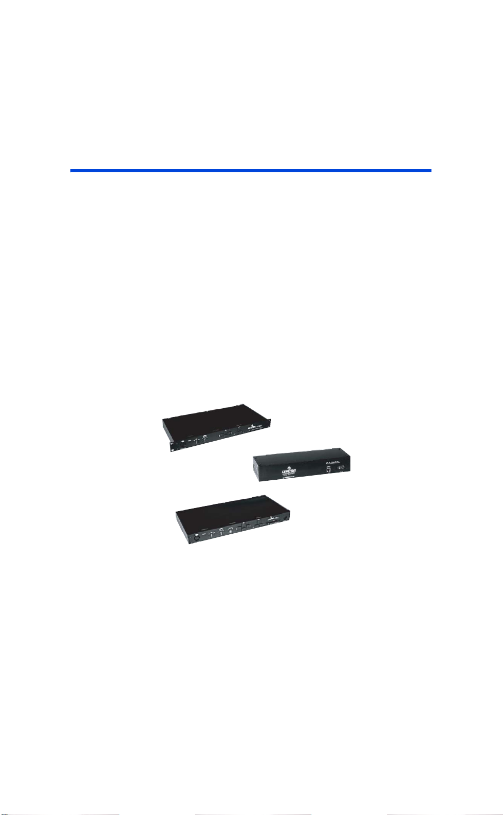
Figure 1: NPC Product Line XP, DHV and DLR
Rev: A20031222.sw3.10 Page 3
Page 5

User Guide
Currently there are three models of the NPC available, each of
which support the following interfaces:
XP
DHV
DLR
Model
DMX
3
3
Inputs
DMX
Outputs
3
3
11
Remote
Handheld
1
1
Keyboard
1
Video
Outputs
2
2
Lan's
LunaNet
2
1
Cards
Memory
1
To facilitate communication between these devices your NPC allows
you to:
Create quick port to network patches
Create quick network to port patches
Patch channels from the network to channels on a port
Patch channels from a port to channels on the network
View video displays produced by other ColorNet
enabled equipment
Although the concepts, routines, and functions for installation and
configuration are similar for all three models, this manual is
specifically tailored for the DHV model.
Analog
16
Inputs
Page 4
Definitions
Here are some common words you will find in this manual which
may require a little more definition.
Channel – A channel usually refers to an individual unit of control
on the Luma-Net network. However the word channel sometimes is
used to reference an individual DMX address or a fader on a control
device or theatrical console. If you pay careful attention, you will be
able to determine the meaning by it’s context.
Page 6

User Guide
ColorNet – ColorNet is Leviton’s network protocol used to carry
lighting control signals over Ethernet wiring using TCP/IP. For
additional information on ColorNet see the appendices to this
document.
DMX – (Short for DMX512, a USITT Standard) A digital multiplexed
control protocol used to control lighting devices like dimmers,
effects, and automated lighting.
DMX Universe – A DMX universe is a virtual or physical group of
512 DMX addresses. In the physical world, a DMX universe
represents a DMX input or output from a source of control like a
control console or NPC. In the virtual world, like on the ColorNet
network, a DMX universe is just simply a common group of 512
DMX channels. All DMX signals on the ColorNet network belong to a
virtual DMX Universe.
Ethernet – Ethernet is a networking term which describes the
physical devices and equipment used to inter-connect networking
equipment. When a network is referenced as an ‘Ethernet network’
it describes a certain set of components used to interconnect
computing equipment.
IP Address – An IP (Internet Protocol) address is a way to
reference a particular node on a network which speaks the TCP/IP
protocol. The IP address can be user defined and set via the
software for the device. All IP addresses on the same network must
only reference one node.
LC-Net- Leviton’s "CAN" based network which carries data for
some of our architectural products.
Lighting Group – Lighting Groups are used to delineate groups of
Luma-Net channels which operate together (within the same room)
when using room separate/combine Luma-Net functions.
Rev: A20031222.sw3.10 Page 5
Page 7

User Guide
Luma-Net – Leviton’s RS-485 based network which carries control
data for our architectural stations.
MAC Address – a unique network address which identifies a piece
of networking hardware to be used on an Ethernet network. The
MAC address of a device can not be changed.
TCP/IP – is a networking protocol or rather suite of protocols
commonly used on Ethernet networks and the internet. TCP is an
acronym for Transmission Control Protocol and IP is an acronym
for Internet Protocol.
Page 6
Page 8

User Guide
Part 1- Initial Set-up & Basic
Configuration
This section of the manual will cover the installation and basic
configuration of the NPC. There are (4) steps required to make
your NPC work:
1.
Physical Installation
2.
Set General & Network Settings
3.
Set Device Connections
4.
Create Basic Patches
Until these steps are complete, your NPC will not be operational.
For advanced configuration of the NPC, please reference Part 2 of
this guide.
Part 1 Contents
Physical Connections.......................................... 8
Installation........................................................11
System Status Check.........................................15
Navigation & Front Panel Controls.......................16
Quick Start Configuration...................................18
Rev: A20031222.sw3.10 Page 7
Page 9
User Guide
Physical Connections
The information in this chapter identifies and describes all of the
physical connections, controls, and indicators of the NPC.
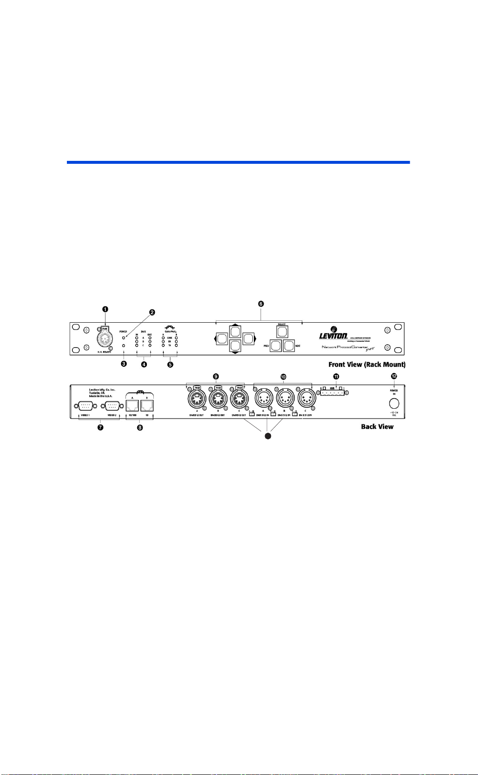
The images below show the front and back views of the NPC. They
are designed to give you an overview of the physical attributes to
the NPC. Use the numbered callouts to cross reference with the
legend/descriptions below.
Page 8
13
Figure 2: NPC DHV Front and Back Views
1) Hand Held Remote Port: A Theatrical Control Console Hand
Held Remote can be plugged into this port to control any ColorNet
2.0 console connected to the network.
2) Power Indicator: This LED will be lit if the NPC is receiving DC
input power.
3) Reset Hole: Push a paperclip through this hole to access the
reset switch.
Page 10

User Guide
4) DMX512 Indicators: Each DMX512 input and output LED
indicators will light green to show activity on their respective ports.
5) ColorNet Indicators: There are two sets of LED indicators;
one set for each ColorNet port. The Link LED indicates whether the
port has established a connection to the ColorNet network. TX & RX
indicates any transmitting or receiving data to or from the network.
6) Navigation & Operation Buttons: Buttons used when
performing local configuration functions. See the chapter titled
“Navigation Button Operation & Requirements”
7) Video Ports: Ports used to connect VGA compatible video
monitors. Each monitor can be configured to display a local or
remote network device video display.
8) Ethernet Ports: Ethernet ports used for connection to a
ColorNet 2.0 TCP/IP Ethernet network.
9) DMX512 Output Ports: Output a standard DMX512 control
signal from the ColorNet network.
10) DMX512 Input Ports: Any device that supplies a DMX512
signal can be connected to these ports. The dimmer information
contained within the DMX512 signal can be patched to any location
on the ColorNet network or directly to an output port.
11) Hand Held Remote Hardwired Port: This port is to be used
for connecting external hardwired connections for a Hand Held
Remote to the NPC. Note: The front panel HHR connector and the
back panel HHR connector are internally connected to each other,
therefore, only one can be used at a time. If either HRR port is
used, the Luma-Net A port must not be used.
12) Power Input Port: Plug the supplied DC Power supply into
this port to supply power to the NPC. The NPC requires +1224VDC, and has a load of 800mA excluding any external loads like
Rev: A20031222.sw3.10 Page 9
Page 11

User Guide
Luma-Net stations or analog devices. The NPC is supplied with a
12VDC, 2.5A power supply.
13) DMX512 Input Termination Switches: Placing one of
these switches in the “1” position connects a 120 ohm resistor
across the signal pins 2 and 3. This should only be done if the
connection to the port is the end of the DMX512 run.
Page 10
Page 12

User Guide
Installation
The installation and physical connections to the NPC should be
pretty straight forward and for many may be self explanatory.
However, here is a brief explanation of the required steps and any
important notes.
Physical Installation & Power
Install the device into it’s physical location. If the device is to be
rack mounted, install it into the rack. If it’s to be table top mounted,
set it up on the table.
Observe clearances as required for proper device operation.
Front panel access for local configuration and visual status
indication, and rear access for connections. Be sure to leave
enough room for the connector!
Prepare the power connections, but do not yet connect power.
Power should be the last thing connected after all other
connections have been made.
ColorNet Network Connections
1 Connect ColorNet Port A to your Ethernet hub for
interface to other ColorNet devices.
2 If your NPC is near an i Series dimming rack, and
your system requires it, you may connect ColorNet
port B to the dimming rack processor.
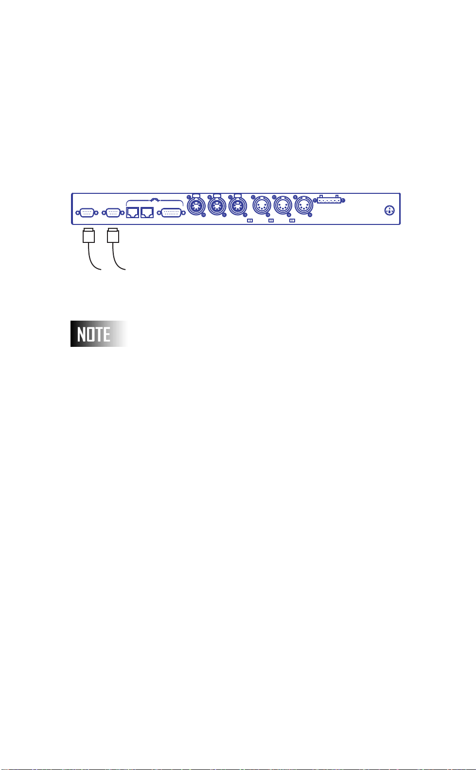
Connect a video monitor to Video Port #1 and/or #2 as
required. Remember when connecting to a network hub, a
straight through network patch cable should be used. If
connecting directly to another device, a special type of cable
referred to as a "crossover cable" should be used. This type of
cable swaps the send/receive pairs so that network integrity is
maintained.
Rev: A20031222.sw3.10 Page 11
Page 13
User Guide
Video Connections
Leviton Mfg. Co. Inc.
Tualatin, OR.
Made in the U.S.A.
VIDEO 1 VIDEO 2 10/100
A10B
B
AUI
PUSH PUSH PUSH
AB
DMX512 OUT
DMX512 OUT
CA
I - O
DMX 512 IN
DMX512 OUT
B
I - O I - O
DMX 512 INDMX 512 IN
HHR
C
To Video Monitors
Even if a video monitor is not being used in the permanent
installation, it is helpful if not required for initial setup/
configuration.
POWER
IN
+15
VDC
Page 12
Page 14
User Guide
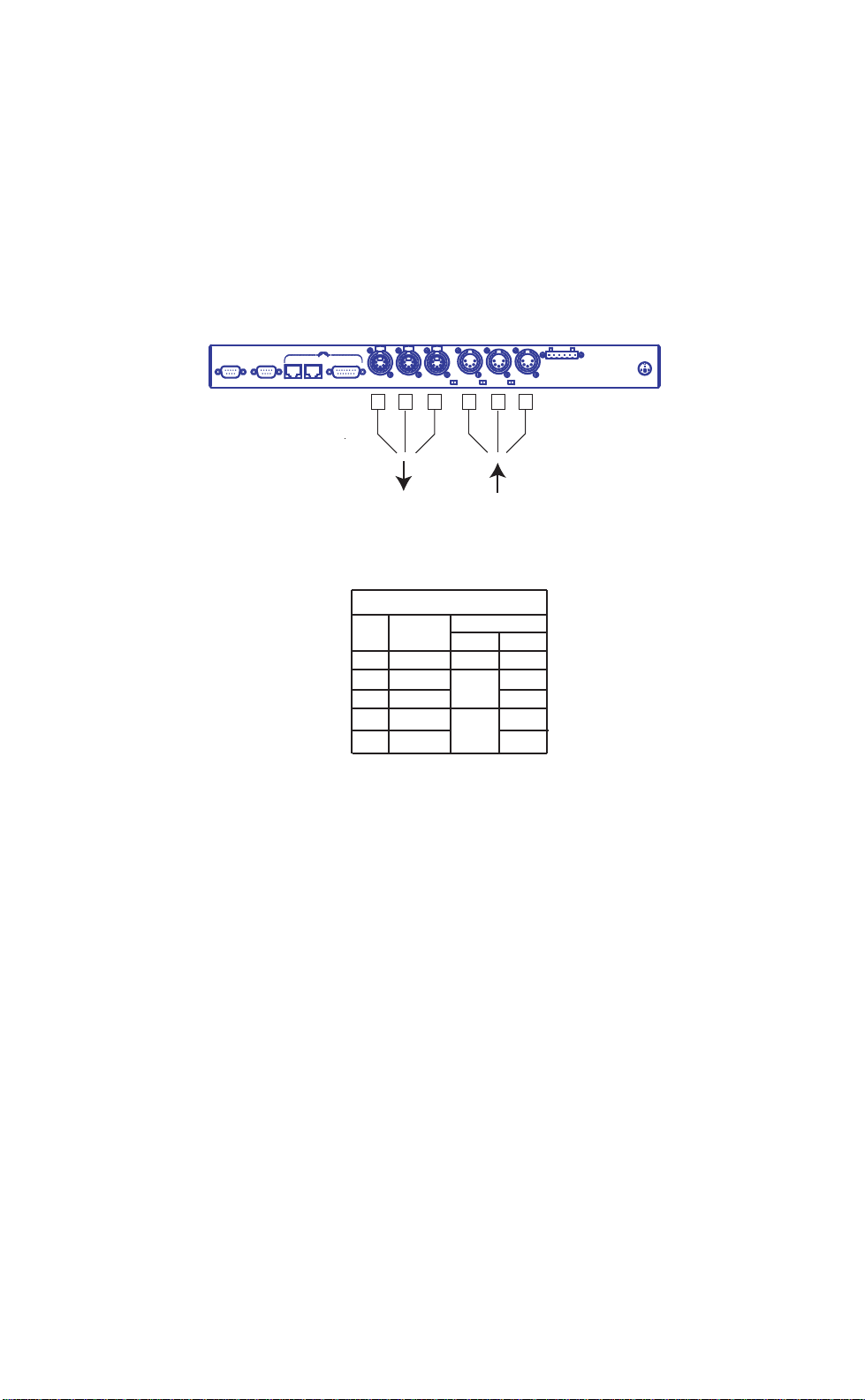
DMX Connections
Connect any required DMX input or output devices
Leviton Mfg. Co. Inc.
Tualatin, OR.
Made in the U.S.A.
VIDEO 1 VIDEO 2 10/100
A10B
B
AUI
PUSH PUSH PUSH
AB
DMX512 OUT
DMX512 OUT
CA
DMX512 OUT
Connect any required
DMX Inputs or Outputs
DMX Data
Output
(Not all required connections)
0,1,2,3 Outputs
0,1,2,3 Inputs
DMX Pinout
Pin
Function
Common
1
2
Data 1Data 1+
3
Data 2-(N/C)
4
Data 2+(N/C)
5
Figure 3: Device Connections
B
I - O
I - O I - O
DMX 512 IN
DMX Data
Input
Wire (Belden 9829)
Pair Color
Shield
-
1
2
White
DMX 512 INDMX 512 IN
Black
Red
Black
HHR
C
POWER
IN
+15
VDC
Rev: A20031222.sw3.10 Page 13
Page 15
User Guide
POWER
B
C
DMX
A
IN OUT
RX
TX
ColorNet
A
LINK
B
H. H. REMOTE
e
e
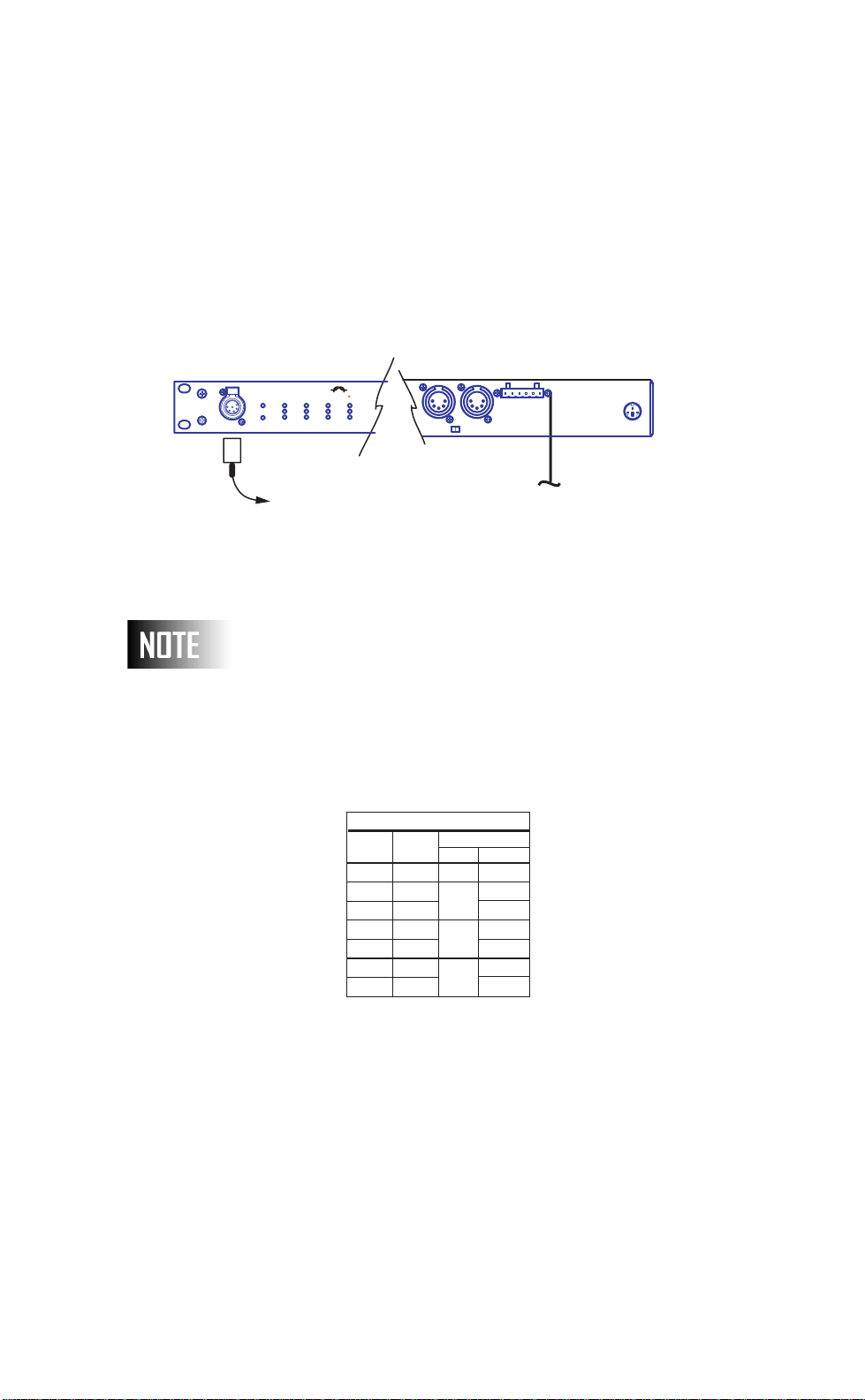
Handheld Remotes
Connect Handheld remote to front or back of NPC.
Front
PUSH
R
BC
I - O
DMX 512 INDMX 512 IN
HHR
POWER
IN
+15
VDC
Back
To hardwire building
To Handheld Remote
HHR Wiring
Terminal
If a handheld remote is used, either hardwired or otherwise,
you must abandon the Luma-Net A port.
Handheld Remote (HHR)
Function
Common
Common
+12VDC
RXRX+
TXTX+
Wire (Belden 9830)
Color
Pair
Shield
-
White/Blue
1
Blue/White
White/Orang
2
Orange/Whit
White/Green
3
Green/White
Pin/
Terminal
1
1
2
3
4
5
6
Page 14
Figure 4: Handheld Remote Physical Connections
Page 16
User Guide
POWER
B
C
DMX
A
IN OUT
RX
TX
ColorNet
A
LINK
B
H. H. REMOTE
System Status Check
Make your final power connections and apply power.
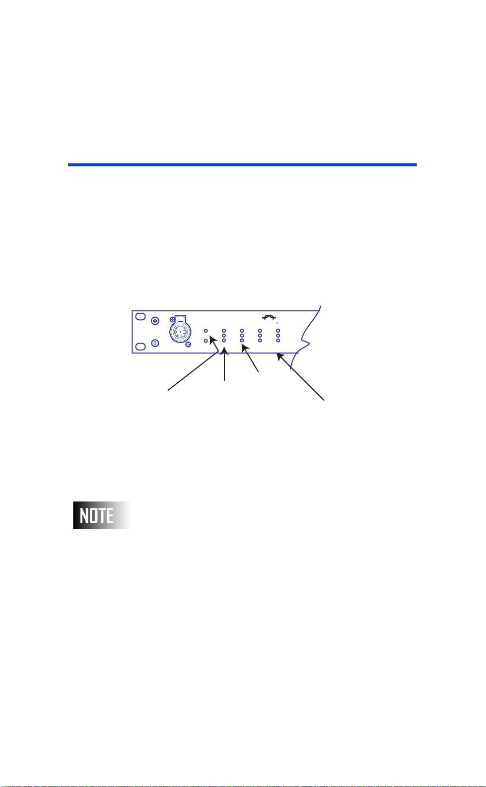
At this point in time, your NPC should be operational. There’s a bit
of configuration which must still be done, but all your connections
are made. To checkout the system, observe the LED’s on the front
of the unit.
Indicates Power
Connector
Figure 5: Successful Status of LED
LED’s may not be lit as expected with default configuration.
PUSH
Indicates
DMX Data
Received
R
}
Indicates
Transmitting DMX
Data
Network Connection
Status
Rev: A20031222.sw3.10 Page 15
Page 17
User Guide
Navigation Button Operation &
Requirements
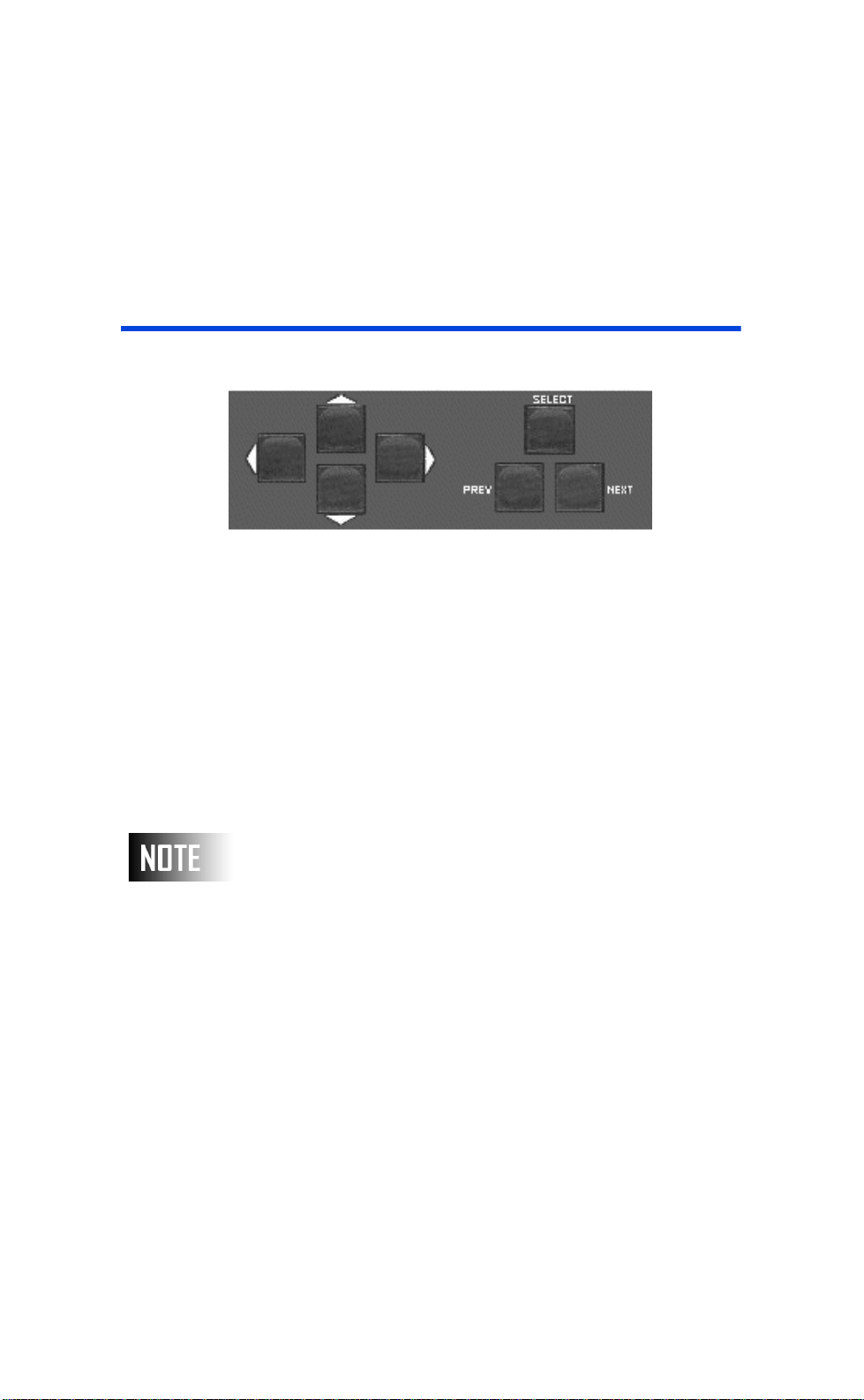
Figure 6: NPC Front Panel Buttons
The basic operation of the NPC is made simple through the use of
the seven buttons located on its front panel. These buttons have
two primary sets of functions, the first group of buttons, [UP],
[DOWN], [LEFT] and [RIGHT], are purely for navigation. They
are used to move the cursor around the video display. The second
group of buttons is used to modify parameter values or settings.
[SELECT] is used to "select" a menu choice, save changes, or
return to the previous screen. [PREV] (short for "previous") and
[NEXT] are used to step through the parameter options or to
increment/decrement a number.
Page 16
Sometimes, you will be using the [NEXT] and [PREV] buttons
to scroll through a large range of values, like the alphabet. In
this situation, you can press and hold the button which will
quickly scroll through the values instead of repeatedly pressing
the buttons.
Page 18

User Guide
Generally, a typical use of the navigation & operation
buttons will be as follows:
Step 1 From the Main Menu, use the
[UP][DOWN][LEFT][RIGHT] navigation
buttons to select the main menu option
you desire.
Step 2 When you’ve reached your desired main
menu option, press the [SELECT] button.
Step 3 You now will be looking at a configuration
or status screen. From this point you use a
combination of the
[UP][DOWN][LEFT][RIGHT] arrow
keys to get to your desired option.
Step 4 Then use the [NEXT][PREV] button to
make changes.
Step 5 Repeat steps 3 & 4 until all settings have
been changed.
Step 6 Press the [SELECT] button. This will
either return you to the previous screen or
ask if you want to save changes. If you are
asked if you want to save changes,
pressing the [SELECT] button again will
save them. Pressing any other key will
cancel the changes.
These are the basics of using the navigation & operation buttons.
In some screens there are additional options or requirements which
will be covered in the section of the manual which describes those
areas.
Rev: A20031222.sw3.10 Page 17
Page 19

User Guide
Part 2- Quick Start
This chapter is designed to quickly get you up and running with the
basic functionality of the NPC. However, it’s certainly not all
inclusive. If after performing the steps in this chapter your NPC is
not operating correctly or you need additional configuration
options, please reference the remainder of the manual.
Step 1- Installation, Connections and Power
Install the NPC as required, make all data connections and apply
power as discussed in the previous chapter.
Page 18
Page 20
User Guide
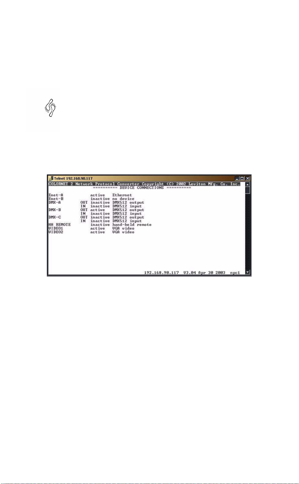
Step 2- Device Connections
Verify all device connections from the "Device Connections" options
from the main menu. The port setting should be set correctly to no
no device
connected to that port, and the port status should read active or
inactive based on their current connection state.
or otherwise based on whether or not something is
Figure 7: Quickstart Device Connections Screens
Rev: A20031222.sw3.10 Page 19
Page 21
User Guide
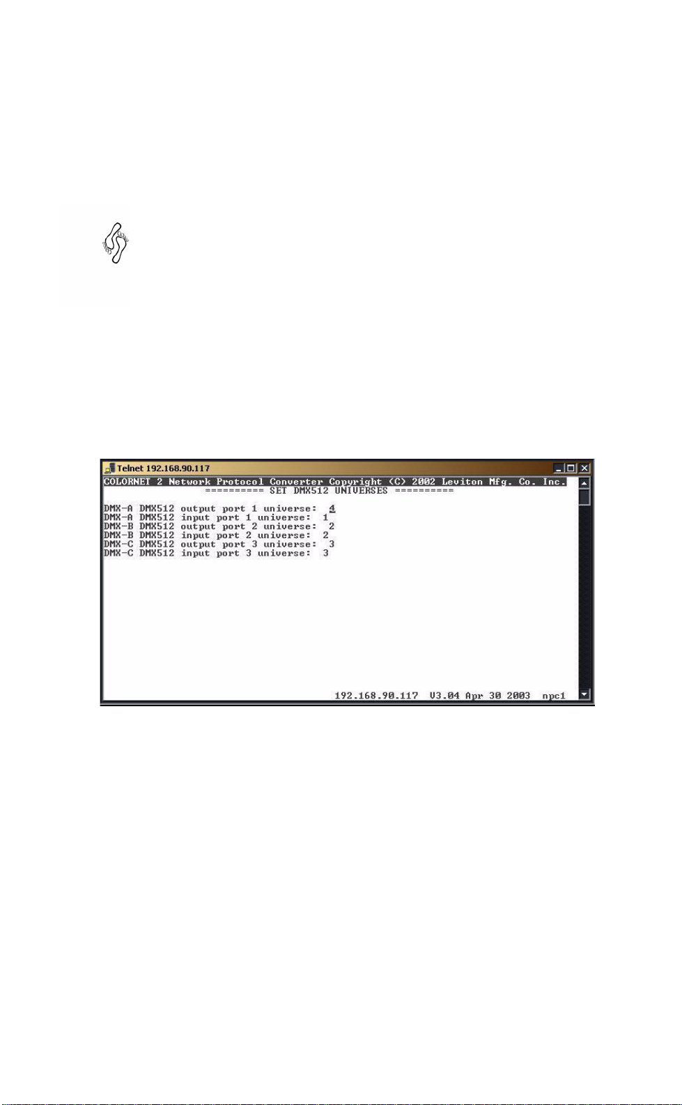
Step 3- Quick "Simple" Patching
From the "Universe Numbers" option off of the main menu you can
create a set of basic patches which assign physical ports on the
NPC to ColorNet Universes. Simply use the arrow keys to move
through the display and change each number to your requirements.
The screen shown above only has DMX-A and DMX-B available
because in the device connections screen (see step 2) DMX-C was
set to "no device". When you are done setting up your basic
patches, press the Select button to exit and save your settings.
Page 20
Figure 8: Quick Start Universe Patching
That is all there is to Quick Start Configuration. If you require
advanced patching or other custom configuration options, you will
find detailed information throughout the remainder of this
document.
Page 22

User Guide
Part 3: Wrapping Up
This section of the manual will show you the basic procedure steps
to advanced configuration without spending anytime explaining the
"why’s" of what you are doing. Each procedure references a section
of the manual in Part 3 where you can find additional information
on the procedure.
Setting the IP Address
Procedure: Setting the IP Address or Configuring
the NPC to use DHCP
Step 1 From the Main Menu, use [UP] [DOWN]
to navigate to "General Set-up", then Press
[SELECT].
Step 2 Use [UP] [DOWN] to navigate to the
hard-coded IP address.
Step 3 Use [PREV] [NEXT] and [LEFT]
[RIGHT] to enter your desired IP address
field
-OR-, if DHCP is desired
Step 4 Use [UP] [DOWN] to Navigate to the
DHCP for IP address field.
Step 5 Use [NEXT] [PREV] to set the value to
yes.
Step 6 Press [SELECT] once to exit then press
[SELECT] a second time when requested
to confirm the save.
Procedure: Enabling the power loss memory restore
feature
Used to determine the behavior of the NPC upon power loss and
restore. If set to yes, NPC will periodically memorize the current
look. Then, upon power failure, will restore the look. If set to no,
this feature is not enabled.
Rev: A20031222.sw3.10 Page 21
Page 23

User Guide
Procedure: Creating a quick local port to ColorNet
patch
Step 1 From the Main Menu, use [UP] [DOWN]
to navigate to "General Setup" and then
press [Select].
Step 2 Use [UP] [DOWN] to navigate to "Luma-
Net" levels non-volatile save.
Step 3 Use [NEXT] [PREV] to set the setting to
"YES".
Step 4 Press [SELECT] once to exit then press
[SELECT] a second time when requested
to confirm the save.
Step 1 From the Main Menu, use [UP] [DOWN]
to navigate to "DMX Universe Numbers"
and then press [SELECT].
Step 2 Use [UP] [DOWN] to navigate to the
desired local input port.
Step 3 Use [NEXT] [PREV] to set the ColorNet
Universes.
Step 4 Press [SELECT] once to exit then press
[SELECT] a second time when requested
to confirm the save.
Page 22
Procedure: Creating a quick ColorNet to local port
patch
Step 1 From the Main Menu, use [UP] [DOWN]
to navigate to "DMX Universe Numbers"
and then press [SELECT].
Step 2 Use [UP] [DOWN] to navigate to the
desired local output port.
Step 3 Use [NEXT] [PREV] to set the ColorNet
Universe.
Step 4 Press [SELECT] once to exit then press
[SELECT] a second time when requested
to confirm the save.
Page 24

User Guide
Procedure: Set a Display to show a DMX output
Step 1 From the Main Menu, use [UP] [DOWN]
to the "Select Video 1 Display" or other
display as desired and press [SELECT].
Step 2 Use [UP] [DOWN] to highlight "DMX512
Output Trace" and press [SELECT]
Step 3 If you want this display to be the "Default"
display, meaning that it is the display
shown on boot: Use [UP] [DOWN] to
highlight "Set Default" and press
[SELECT].
Step 4 Use [UP] [DOWN] to highlight "Exit" and
press [SELECT].
Step 5 You are now viewing the DMX output
trace.
Step 6 Use [NEXT] [PREV] to toggle between all
DMX output ports.
Rev: A20031222.sw3.10 Page 23
Page 25

User Guide
Part 4: Advanced Config. & Operation
This section of the manual covers all advanced configuration
options and operation of the NPC.
Configuration of the NPC can be as simple or as complex as you
need it to be. Every installation is unique with it’s own requirements
so to tell you how to explicitly configure your unit for your
environment would be inappropriate. Instead we show you all of
the configuration options and parameters so that once you
understand how the NPC works, you’ll be able to take advantage of
it’s powerful features.
We will assume for purposes of this guide that you are configuring
the NPC locally meaning that you have a video display device
attached to the video port of the NPC and are configuring using the
front panel navigational buttons. If you are configuring the device
via the Telnet interface, you will find it helpful to review the chapter
on Configuration by Telnet or keyboard. The concept will be the
same, the interface and keystrokes are just slightly different.
Part 4 Contents
Main Menu.........................................................25
General Setup....................................................27
Device Connections.............................................32
DMX Universe Numbers.......................................36
Patching.............................................................38
Patch Manipulation..............................................42
Lighting Groups...................................................50
Event Log...........................................................53
Selecting Displays...............................................55
File Transfer........................................................60
Page 24
Page 26
User Guide
Main Menu
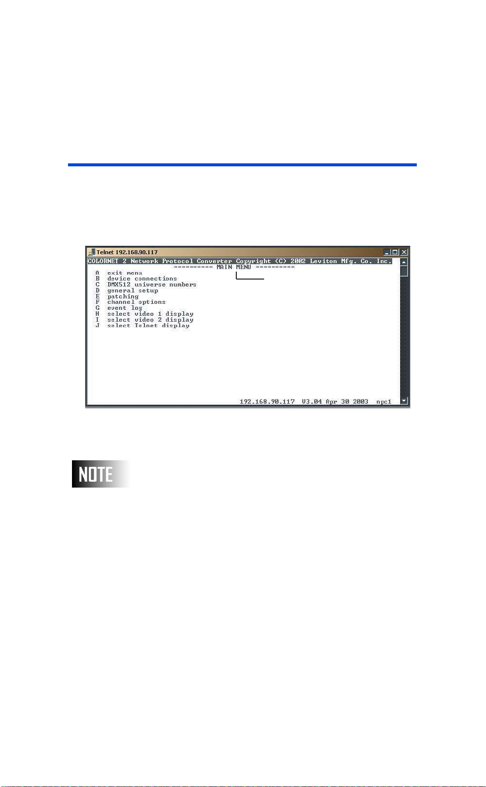
This chapter outlines all options off of the main menu and the
configuration and/or actions which can be achieved upon their
selection. A more in depth discussion of each option and its usage
can be found later in this manual.
Main Menu
Menu Options
Menu Options
}
IP
Address
Figure 9: NPC - Main Menu
If the Main Menu is not visible when you approach the NPC,
pressing the [SELECT] button will toggle between the default
display and the main menu.
The available options on this menu are as follows:
Exit menu – This option will clear the screen of the Main Menu
and begin displaying the selected default display, or a Trace screen
if no default has been defined.
Device connections – is used to set which physical ports will
accept or send data and show which connections the NPC believes
to have connected devices.
}
Software
Version
}
Current
Date
}
Name of
NPC
}
Rev: A20031222.sw3.10 Page 25
Page 27

User Guide
DMX512 universe numbers – this is a quick way to set some
universe based patches.
General setup – from this screen you can set the general,
network, and identification settings for this NPC.
Patching – this is where you define what data is routed to all of
the input/output connections on this NPC.
Channel options – allows you to define what happens upon loss
or competition among input signals
Lighting Groups – Lighting groups are used to define the groups
of Luma-Net channels which operate together or apart in a room
separate/combine scenario.
Event Log – For use by tech services when troubleshooting
problems.
Page 26
Select Video 1/Video 2/ Telnet Display – Allows you to define
what screen displays on the NPC Video 1/Video 2/Telnet display
other than the main menu.
Page 28
User Guide
General Setup
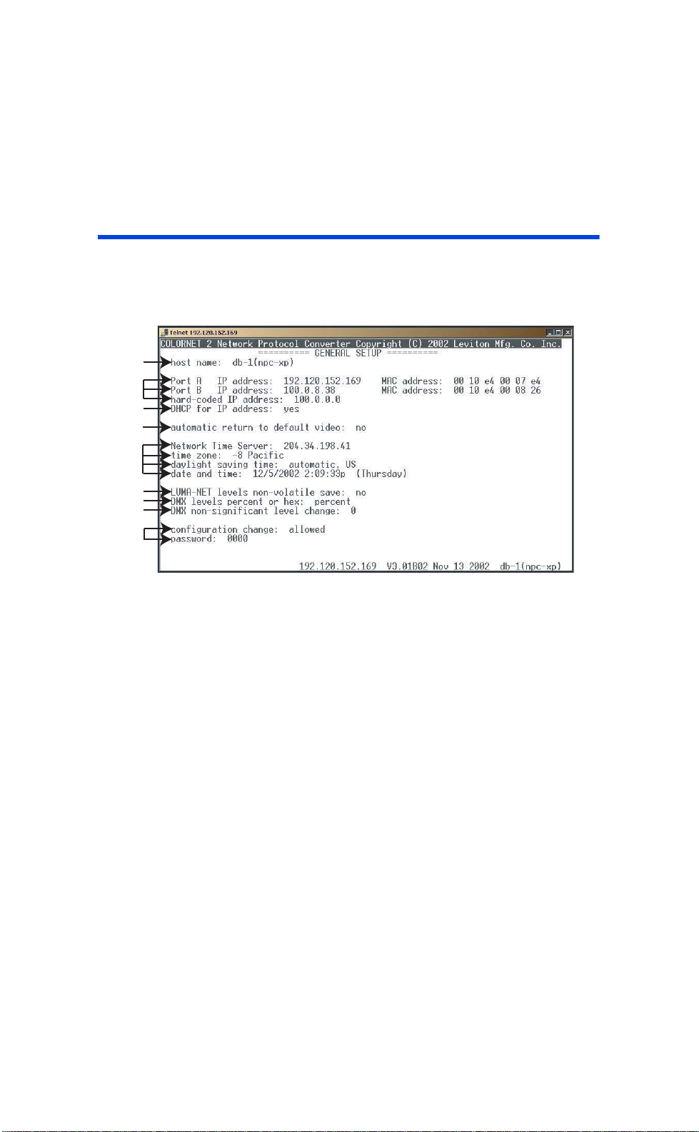
The General Setup screen is where you define most of the basic
information which is required for operation.
A
B
C
D
E
F
G
H
I
Figure 10: General Setup
A. Host Name
The Host name is a means of identifying the NPC node in a human
way. The host name can be any text up to 12 characters long and
should not contain any spaces. Although not a requirement at this
time, it is recommended that each host name be unique. When
inventorying the network with the LumaEdit configuration
application, or viewing remote devices, each NPC will display both
it’s IP address and it’s host name.
B. Current Network settings
This section displays which Ethernet ports are active. For each
active port, the NPC also shows the current IP and MAC address of
the NPC. The MAC address is factory set and is not user
changeable. A MAC address is a means of identifying a particular
piece of networking hardware which is guaranteed to be unique—
even across different manufacturers.
Rev: A20031222.sw3.10 Page 27
Page 29

User Guide
C. IP Address Assignment Method
The concept of the IP address is significant because this address is
what allows the software of all networking devices on the ColorNet
network the ability to uniquely identify this device. On a TCP/IP
Ethernet network, each device must have it’s own unique IP
address. No two devices may share the same address. (see
appendix on TCP/IP Ethernet Networking for more information)
These fields allow you to determine how the NPC gets it’s IP
address. There are three methods by which an NPC can gets it’s IP
addresses assigned:
1. Hard coding the address,
2. DHCP,
3. NPC Auto-Addressing Algorithm
IP Address Assignment: Hard Coding the Address
Hard coded IP addresses should be used when you know exactly
what you want the IP address of the NPC to be.
Page 28
A hard coded IP address can not be set for Port B, for Port B
either DHCP or the NPC Auto Addressing Algorithm is used to
set the IP address.
Procedure: To use a hard coded IP Address:
Step 1 From the general setup screen, scroll to the
hard-coded IP address field
Step 2 Using the [PREV] [NEXT] arrow keys,
enter your desired IP address
Step 3 Verify that the DHCP for IP address setting
is set to no. If not,
a. Use the arrow keys to navigate to
the DHCP for IP address setting
b. Use [PREV][NEXT] to select NO
Step 4 Press [SELECT] to initiate a return to the
main menu and [SELECT] again to save
changes.
Page 30

User Guide
To use a hard coded address, simply enter a valid and unique IP
address into the hard-coded IP address field. A hard coded IP
address is used at all times when a hard coded IP address is
defined and the DHCP for IP address field is set to NO.
IP Address Assignment: DHCP
If you have a DHCP server on your network, you can allow it to
assign your IP addresses. This will ensure that there are no IP
address conflicts on your network. For this to take place, simply
leave the hard-coded IP address alone and set the DHCP for IP
address field to
yes
. When the DHCP for IP address field is set to
yes, it does not matter what the hard-coded IP address is set to.
Upon boot-up, the NPC looks for a DHCP server. If one is found, it
gets an IP address lease. If one is not found, it defaults to the hardcoded IP address or the auto assignment algorithm.
IP Address Assignment: Automatic by NPC
The final method by which your NPC can get an IP address is with
the NPC auto-addressing algorithm. The auto-addressing is
guaranteed to assign unique addresses when ONLY Leviton LCD
ColorNet 2.0 products exist on the network. That is to say that if
ethernet products from other manufacturers are used, IP address
duplication may occur rendering the network inoperative.
Summary of Settings
Step 1 If DHCP= YES and DHCP server IS found,
the DHCP server will return an IP address.
Step 2 IF DHCP= YES and DHCP server IS NOT
found, hard coded IP address is used.
Step 3 IF DHCP= NO or DHCP server IS NOT
found and hard coded address is set to an
IP address, the hard coded address is use.
Step 4 IF DHCP= NO or DHCP server IS NOT
found and hard coded address has 0’s in
the right most octet(s), the autoassignment algorithm is used.
Rev: A20031222.sw3.10 Page 29
Page 31

User Guide
D. Automatic return for default video
E. Date, Time, & Location
The first, leftmost number of the IP address is not allowed to
be zero. If the NPC detects a zero is recorded in that position, it
will default to 100 when the NPC generates the actual IP
address.
By setting this function to yes, the video monitor will be switched
to the default screen after 5 minutes of inactivity. The default
screen is set under the “select video 1(2)” display options on the
main menu. See this section of the manual for additional
information. With this option set to “no,” the default display is only
recalled upon power up.
These settings allow you to set some basic environmental
information.
The Date and Time set the current date and time. If you have a
network time server on your network, or have direct access to the
internet, you can set it’s IP address in the Network Time Server
field and the NPC will use this information to override the local
settings.
Page 30
The Network Time Server is a device used on IP Ethernet
networks which gets it time from an authoritative source of
time and then allows other devices to set their time from it. An
authoritative source of time is simply a computer on the
network which has the current date and time AND this
information is guaranteed to be correct within a reasonable and
predictable margin of error. Traditionally, an authoritative
source is defined as a first or second tier time server. The first
tier servers have usually a Radio Wave receiver which receives
a broadcast of the Greenwich Mean Time and Julian date
information. These servers then in turn have a Network Time
Server connected to the internet running multiple time service
protocols. The second tier servers then set their time from the
first tier servers. It’s recommend that all Third Tier servers and
other clients set their time from the second tier servers so as
not to over burden the first tier servers. A third tier is usually
a network time server on your local network. The NPC uses the
Page 32

User Guide
NTP network time protocol. If you have an NTP server on your
local network, set the IP address to this server. If you don’t but
the NPC does have access to the internet, you can allow it to
set it’s time from a second tier server. In this case, use the
factory default setting of 204.34.198.41 which points to the
authoritative time source at the Naval Observatory at Falcon
AFB, Colorado. If neither of these conditions exist, than just
make sure the local Date and Time settings are correct.
Time Zone sets the time zone for the system astronomical time
clock.
The Daylight saving time setting can either be set to automatic
US, automatic Europe, +1 hour, or none.
Location defines the longitude and latitude of the NPC for use by
the systems astronomical time clock.
F. LUMA-NET levels non-volatile save
This setting is used to determine the action upon a restored power
condition after power is lost for one reason or another.
When set to yes, the NPC will periodically save the current channel
levels as set by the incoming Luma-Net and DMX signal. Then, if
the NPC loses power for one reason or another, upon the
restoration of power, the NPC automatically recalls the last saved
look.
• no – this setting defeats the save option.
• yes –this setting enables the option.
• clear – this setting clears the non-volatile memory
on board the NPC.
G. DMX levels percent or hex
The setting changes the scale of displayed information between
percent, 0-100, and hexadecimal, 00-FF (0-255 in decimal).To
display levels in hex, change this setting to hex, and to display in
percent/decimal notation, set it to percent. This setting can effect
more than just DMX levels.
Rev: A20031222.sw3.10 Page 31
Page 33

User Guide
H. DMX non-significant level change
I. Configuration Protection
Levels, which are affected by this setting, are all DMX levels, LumaNet levels, and Luma-Net address settings.
Unless a qualified user is performing some very specific debugging
of a system, leave this value set to percent; it is much easier to
comprehend.
When two controllers, which control the same channels, are
operating in a "take control" manner, (when two controlling device
control the same channel and the last device with a change takes
control over the previous device regardless of the level of change)
this setting defines how much of a change the last device must
make before the take control occurs. This is necessary because
some sources, like DMX, tend to flutter. You don’t want a flutter
resulting in a 1/10% change to cause a take control to occur. This
could result in erratic behavior. This setting prevents this from
becoming an issue by defining the amount of change required for
take control to occur.
When NPC’s are permanently installed, you might want to restrict
access to those who can make configuration changes. To enable
this feature, set the Configuration change field to locked. Then,
when prompted, enter a password. Next time you need to make
configuration changes, you must enter this password into the
password field before attempting to save changes.
Page 32
The default password used for FTP access can be changed by
setting the password on this screen to anything other than
0000. When the password here is not 0000, that is also the
password for FTP. (Make sure configuration change is set to
‘locked’)
DEVICE CONNECTIONS
This page allows you to view the connection status of every port on
the NPC and on some can manually enable or disable the port. An
enabled device/port is said to be active and a disabled or nonexistent device/port is said to be inactive.
Page 34
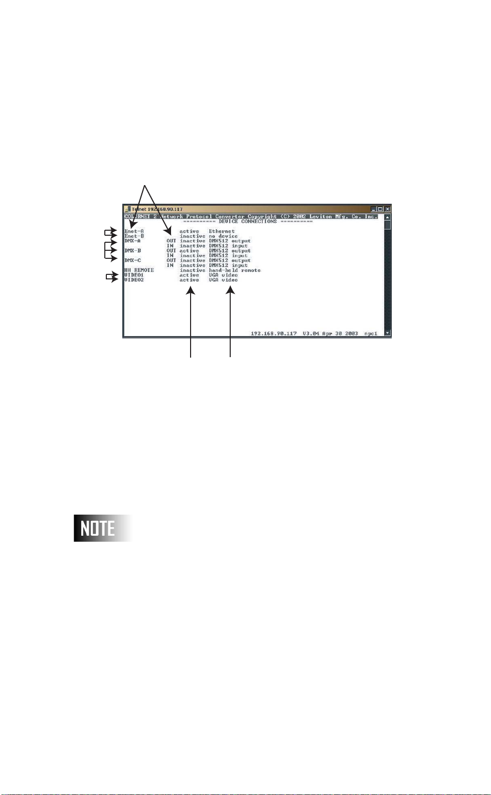
User Guide
Physical Ports
A
B
C
Port Status Port Assignment
Figure 11: Device Connections
From the main menu, use the cursor keys to highlight the item
“device connections.” Pressing the [SELECT] button will bring
up the display shown in figure 4.3. This display shows the status of
inputs and outputs of this NPC. To make changes, simply use the
arrow keys to move the cursor to the desired item. Then, use the
[NEXT] or [PREV] buttons to cycle through the available options.
The available options are listed below.
On all of the available connections below, the status column
will indicate either active or inactive. A port is active if either
the NPC detects presence of input signal on that particular port
or if the NPC is generating a signal on that particular port. If
the status of this port is not what you expect, first verify that
your patching at the NPC is correct. In the case of an input
port, verify that your input signal exists and is transmitting
data. If you are still having trouble, contact tech services.
Rev: A20031222.sw3.10 Page 33
Page 35

User Guide
A. Enet-A and Enet-B
The word active or inactive is shown to indicate if the NPC detected
a connected device. The options for this item are Ethernet, i-Series
or no device. These settings should be set to Ethernet if that port is
connected to a ColorNet network. I-Series, if it’s connected only to
an i-Series dimmer rack, or optionally no-device, you want to
forcibly disable communications on that particular port.
B. DMX-A, DMX-B and DMX-C
The word active or inactive is shown to indicate if the NPC is
receiving or outputting DMX512 data. The options for the input and
output lines are either DMX512 or no device. A setting of no-device
will completely disable this particular DMX input or output.
If and hand held remote is used, either hardwired to the back
of the unit or plugged into the port on the front of the NPC, the
Luma-Net A port can not be used and MUST be set to handheld remote in the Device Connections.
Page 34
C. VIDEO1:
Video 1 is always active and cannot be turned off.
C. VIDEO2:
The option for this item is either VGA video or no device. The word
active is displayed if this selection is set to VGA video and inactive if
it is set to no device.
Changing Port Assignments to:
No Device
There is significant advantage to setting any unused ports to "no
device" frees up the processor for other tasks. The NPC processor is
very busy answering/responding to network requests such as
processing Luma-Net fade commands, patching DMX, and other
Page 36

User Guide
responsibilities of the NPC. Setting ports to "no device" indicates to
the NPC that the processor can ignore that port and move on to
other tasks.
Saving Changes
When any changes are made, pressing [SELECT] will display the
question "save changes” Pressing [SELECT] again will save the
changes and exit back to the main menu. Pressing ANY other
button will discard the changes and exit back to the main menu.
Rev: A20031222.sw3.10 Page 35
Page 37
User Guide
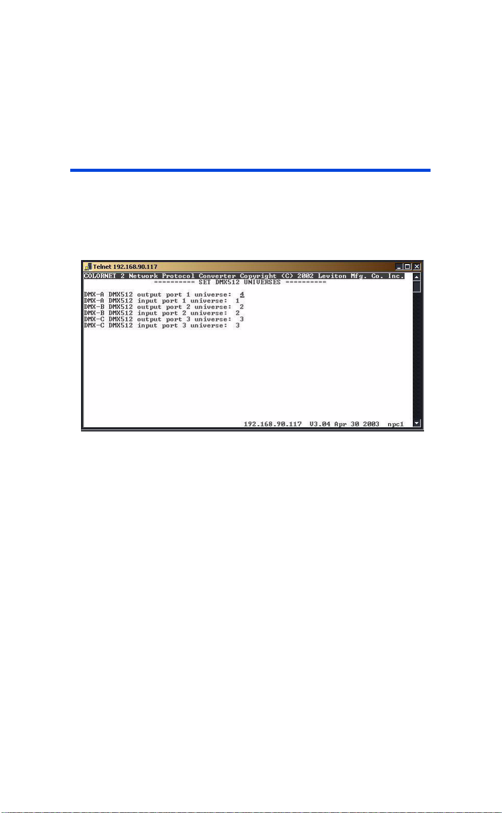
DMX Universe Numbers
This area of configuration is designed to give you a quick means to
create and maintain some basic patches. The patches are between
a physical port on your NPC and a ColorNet universe.
Page 36
Figure 12: DMX512 Universes
To assign a physical port to a ColorNet port, use the following
procedure:
Procedure: Quick Physical Port Patch
Step 1 From the Main Menu, press [UP][Down]
as required until "DMX Universe Numbers"
is highlighted, then press [SELECT].
Step 2 Us [UP][Down] until the desired port is
selected.
Step 3 Use [NEXT][PREV] to make changes to
the selected option.
Step 4 Repeat steps 2 and 3 as necessary.
Page 38

User Guide
Step 5 Set ports to ‘0’ for ports you do not want
patched.
Step 6 Press [SELECT] once to exit the screen,
and [SELECT] a second time to save
changes if prompted.
Assigning a universe number of 0 to any of the ports is same as
saying “I don’t want a patch set for this port.” This is the option
you want if you either want to manually define a patch in the
patching screen, or you just want to simply cut down on NPC
processor or network overhead.
Rev: A20031222.sw3.10 Page 37
Page 39
User Guide
S
Patching
The patching screens are perhaps the heart of the power of the
NPC. These are the screens which control the routing of all
ColorNet data as it passes into and out of the NPC. As you will
recall from the information in the appendices on ColorNet
information, ColorNet carries DMX Universe data, handheld remote
data, and video display data.
Patching is covered in two chapters. The first, which you are
reading now, discusses the concept of
"Patch Manipulation", discusses the management of Patches.
For procedure used to ADD/EDIT/DELETE/CHANGE patches see
page 44.
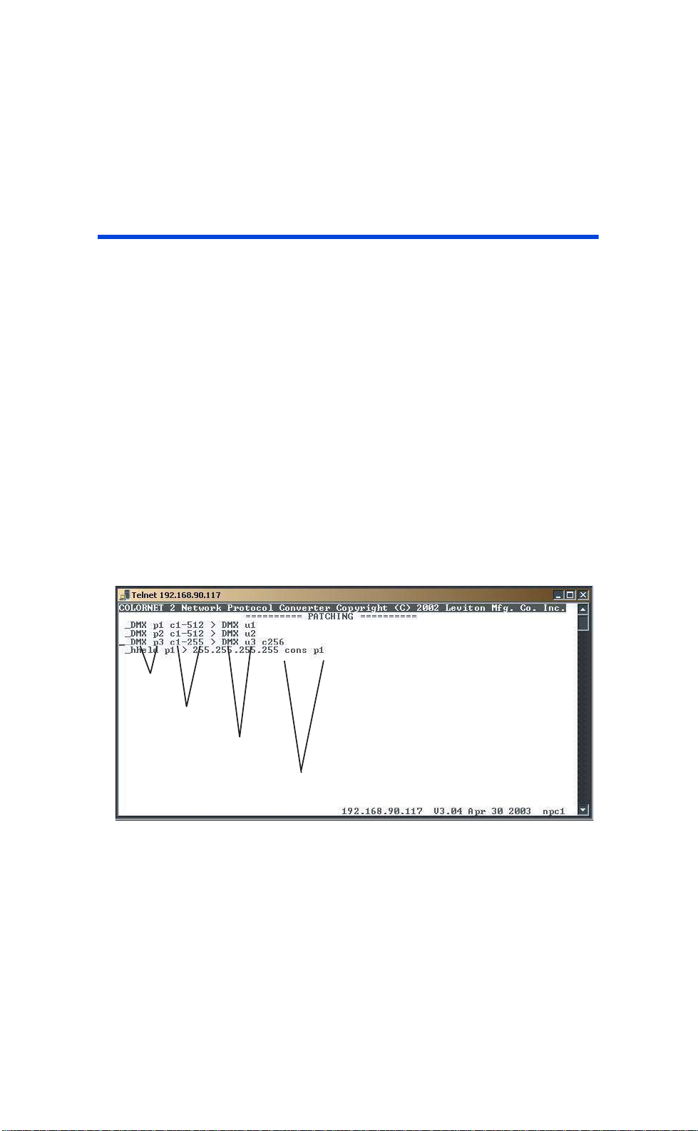
When selecting the Patching options off of the Main Menu, you will
see a screen which looks similar to the following:
Patching
. The second, titled
ource Port
Source Channels
Destination Port
Destination Channel
(If different than source.)
Figure 13: Patching
Page 38
Page 40

User Guide
The information on this screen is a list of all of the patches which
are set for this NPC. Each line represents a patch. The information
on the left side of the greater than (>) sign shows the source or
FROM port information. The information on the right side shows the
destination or TO port information.
Patching
The concept of patching is very similar to old slide or plug
patch. The idea then was that you had a finite number of
dimmers and an infinite number of circuits. The patch you
created simply connected the circuits to the dimmers.
When it comes to the NPC & ColorNet, patching is a similar
concept just applied differently. Refer to the appendices for
detailed information on ColorNet, but for now let’s just picture
ColorNet as a whole bunch of universes where each universe
has 512 control channels.
The patch takes input sources attached to an NPC or coming
from other control device and assigns them to a range of
channels on one of the ColorNet universes. Once the patch is
made, your data is on the ColorNet network.
Now…to get it off of the ColorNet network, you create an
output patch. You take the data from the ColorNet network and
assign it to one of the NPC output ports. Once the patch is
made, your data is routed from the ColorNet Network to your
device.
There are two types of patches which can be created, Devices
Patches and Universe Patches.
Device Patches
Device Patches are patches from a local device (port) to another
local device (port) or to ColorNet. An example of a device patch
could be as follows:
DMX p1 C1-512>DMX u4
Rev: A20031222.sw3.10 Page 39
Page 41

User Guide
Universe Patches
This patch takes channels 1-512 from incoming DMX port 1 and
patches them to the ColorNet, DMX universe #4.
A second example of a device patch of a device patch could be as
follows:
-hheld p1 > 192.168.90.116 cons p1
This patches the hand held remote connected to HHR port 1 (the
only port) to the on line console at IP 192.168.90.116, port 1.
Universe Patches are designed to patch from ColorNet to a local
device/port.
Consider the following patch:
-univ p12 C1-48 > DMXp3 c49
This patch has the effect of taking ColorNet universe #12, channels
1-48 and patching them to the local DMX output port #3, starting
at channel 49 (actually destination channels 49-96, but only the
starting channel is listed).
Page 40
Legend
By now you have noticed that there is a miscellany of nomenclature
involved with patching. Here is a brief key which will help with your
understanding. You will find that even without the key the
nomenclature makes practical sense and with a little practice you
will quickly become an expert.
Types:
DMX p1 -DMX Port #1. If a source, it’s an input. If a
destination, an output.
DMX p2 -DMX Port #2. If a source, it’s an input. If a
destination, an output.
DMX p3 -DMX Port #3. If a source, it’s an input. If a
destination, an output.
hheld p1 -Hand Held Remote, at Port 1.
univ p1 -ColorNet Universe #1 (also p2-p256 for other
universes).
Page 42
User Guide
Destination Types:
DMX p1 -DMX Output Port #1 (also p2 or p3).
x.x.x.x -an IP address of another ColorNet device
DMX u1 -ColorNet Universe #1, (also can be u2-u256 for
other universes).
i-ser p1 -Indicates i Series dimmer rack, port #1.
Other Nomenclature:
c -Indicates channel. C1-48 indicates channels 1-48.
That covers most of the nomenclature. You will see it referenced
throughout the remainder of this chapter and in the next chapter
on patch manipulation.
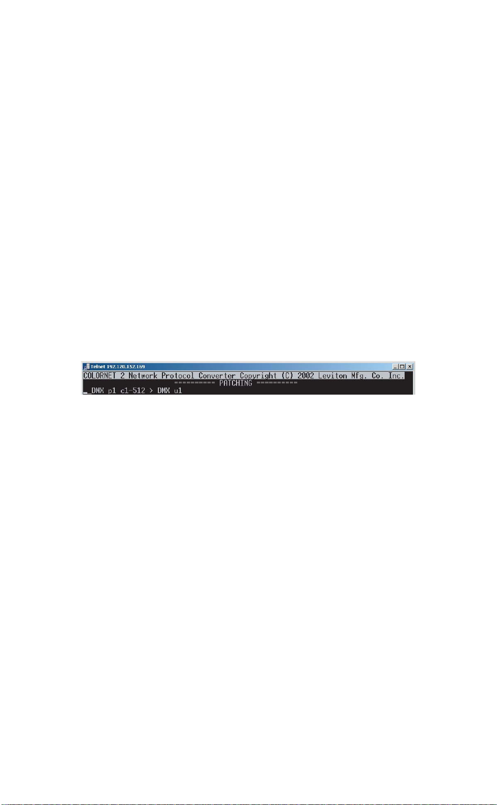
Let’s look at a couple of examples using the information we just
learned.
From this information, we can discover that the input to DMX port
#1, channels 1-512 is patched to ColorNet Universe #1.
Now, let’s look at another example,
univ p1 c1-24 > DMX p3 c25
This patch takes ColorNet Universe #1, channels 1-24, and patches
them into the DMX output port #3 of this NPC, starting at channel
25 consequently ending at channel 48.
Rev: A20031222.sw3.10 Page 41
Page 43

User Guide
Patch Manipulation
To add, change, or delete patches, you access the patch menu by
pressing the [SELECT] button. When pressed, the following menu
appears
Exit Finalize changes, return to
Add Device Patch Patch from a local device
Add Universe Patch network data sent to a universe
Change Change the highlighted patch
Delete Delete the highlighted patch
List Return to patch display
Both the “add device patch” and the “change” functions follow the
same format of question and answer:
Procedure
Step 1 first you define the input device,
Step 2 then input channels,
Step 3 next the destination channels and
Step 4 finally then the destination
main menu
Page 42
from device: DMX512 input P1
channels: 1-512
into channel: 1
destination: universe
The available destinations are “universe”, “local device”, “online
remote device” and “remote device”. When you have set all these
fields, press the down key to get to the output device definition.
What you’ll be asked depends on what patch type you want:
• to universe: universe number
• to local device: actual local device
Page 44

User Guide
• to on-line remote device: you scroll through the
choices
• to remote device: IP address (255.255.255.255
will mean “any”), device type, port number
The choice of output devices will depend on the input device.
The “add universe patch” allows you to patch data from the
ColorNet network to a local port. The series of questions and
expected answers are similar to the device patch above.
Example of typical responses:
from universe: 1
channels: 1-512
into channel: 1
destination: local device
output device: DMX512 output P1
When creating Patches, use the [Down] button to move through
Channel Options
The Channel Options configuration screen is used to control the
behavior of the individual channels or range of channels on a DMX
universe. These settings are used to describe the effects of two
scenarios, the first, what happens when a source signal is abruptly
removed and secondly what behavior shall occur when two
competing sources have the same destination (merging.)
Channel options can be set for each of the DMX output ports.
Rev: A20031222.sw3.10 Page 43
Page 45
User Guide
3
2
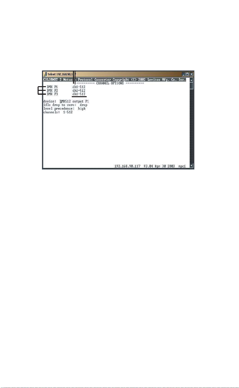
Figure 14: DHV Channel Options
1. DMX Output Port: This describes which Output Port the
Channel Options apply to. DMX P1 references DMX Output Port
DMX P2 references DMX OUtput Port 2 or (B), etc. Depending
on your particular model of NPC, the listing of available ports may
vary.
2. Channel Option Settings: This shows the particular options
set for particular ranges of channels for that particular port. The
first few characters depict the options for the specific numeric
range of channels located adjacent to the characters. The character
legend is as follows:
Page 44
3. idle drop to 0
d= drop to 0
k= keep last level indefinitely
Determines what happens when a DMX in out which
was transmitting data suddenly disappears. The cause
for this could be power failure (at the source, cable
interruption, etc.).
Page 46

User Guide
A drop to setting says that upon loss of signal, the
output will immediately stop outputting DMX.
A keep setting tells the NPC to keep the last level
received indefinitely until new instructions are received.
4. DMX Level Precedence
H= highest level takes precedence
L= last action takes precedence
Determines the plan of action when two patched DMX
Channel Levels are different yet patched to the same
output. If level precedence is set to highest, the
highest level will be the output level at all times. This
option is usually considered a straight merge. If level
precedence is set to last, the last action by any input
determines the output level. Last action precedence is
also referenced as "take control".
Procedure used to set these channel options:
Procedure: DMX Output Port 1
Step 1 Use [UP][DOWN] to get the cursor to the
device field.
Step 2 Use [NEXT][PREV] until "DMX 512
output P1" is selected.
Step 3 Press [DOWN] to advance to the next
field.
Step 4 Use [NEXT][PREV] to set idle drop to
zero to "drop"
Step 5 Press [DOWN] to advance to the next
field.
Step 6 Use [NEXT][PREV] to set DMX level
precedence to high.
Step 7 Press [DOWN] to advance to the next
field.
Step 8 Use [NEXT][PREV] to set the start
channel to 1.
Step 9 Press [RIGHT] to advance past the ‘-’ to
set the end channel.
Step 10 Use [NEXT][PREV] to set the end
channel to "512".
Rev: A20031222.sw3.10 Page 45
Page 47

User Guide
Step 11 Press [DOWN] to complete the entry.
Procedure: DMX Output Port 2
Step 1 Use [UP][DOWN] to get the cursor to the
device field.
Step 2 Use [NEXT][PREV] until "DMX 512
output P2" is selected.
Step 3 Press [DOWN] to advance to the next
field.
Step 4 Use [NEXT][PREV] to set idle drop to
zero to "keep"
Step 5 Press [DOWN] to advance to the next
field.
Step 6 Use [NEXT][PREV] to set DMX level
precedence to high.
Step 7 Press [DOWN] to advance to the next
field.
Step 8 Use [NEXT][PREV] to set the start
channel to 1.
Step 9 Press [RIGHT] to advance past the ‘-’ to
set the end channel.
Step 10 Use [NEXT][PREV] to set the end
channel to "512".
Step 11 Press [DOWN] to complete the entry.
Page 46
Procedure: DMX Output Port3
Step 1 Use [UP][DOWN] to get the cursor to the
device field.
Step 2 Use [NEXT][PREV] until "DMX 512
output P3" is selected.
Step 3 Press [DOWN] to advance to the next
field.
Step 4 Use [NEXT][PREV] to set idle drop to
zero to "drop"
Page 48

User Guide
Step 5 Press [DOWN] to advance to the next
field.
Step 6 Use [NEXT][PREV] to set DMX level
precedence to high.
Step 7 Press [DOWN] to advance to the next
field.
Step 8 Use [NEXT][PREV] to set the start
channel to 1.
Step 9 Press [RIGHT] to advance past the ‘-’ to
set the end channel.
Step 10 Use [NEXT][PREV] to set the end
channel to "96".
Step 11 Press [DOWN] to complete the entry.
Step 12 Use [NEXT][PREV] until "DMX 512
output P3" is selected.
Step 13 Press [DOWN] to advance to the next
field.
Step 14 Use [NEXT][PREV] to set idle drop to
zero to "keep"
Step 15 Press [DOWN] to advance to the next
field.
Step 16 Use [NEXT][PREV] to set DMX level
precedence to "last".
Step 17 Press [DOWN] to advance to the next
field.
Step 18 Use [NEXT][PREV] to set the start
channel to 97.
Step 19 Press [RIGHT] to advance past the ‘-’ to
set the end channel.
Step 20 Use [NEXT][PREV] to set the end
channel to "144".
Step 21 Press [DOWN] to complete the entry
and advance to the device field.
Step 22 Use [NEXT][PREV] until "DMX 512
output P3" is selected.
Step 23 Press [DOWN] to advance to the next
field.
Rev: A20031222.sw3.10 Page 47
Page 49

User Guide
Step 24 Use [NEXT][PREV] to set idle drop to
zero to "drop".
Step 25 Press [DOWN] to advance to the next
field.
Step 26 Use [NEXT][PREV] to set DMX level
precedence to "high".
Step 27 Press [DOWN] to advance to the next
field.
Step 28 Use [NEXT][PREV] to set the start
channel to 145.
Step 29 Press [RIGHT] to advance past the ‘-’ to
set the end channel
Step 30 Use [NEXT][PREV] to set the end
channel to "512".
Step 31 Press [DOWN] to complete the entry.
Step 32 Press [SELECT] to exit the screen.
Step 33 Press [SELECT] a second time to save
changes.
Page 48
So what do these values mean?
Idle drop to Zero: This setting determines what happens upon
less input source signal. For example, let’s say you have a control
source plugged into the DMX input port #1 which you have patched
to DMX output ports #1, #2, & #3. Let’s also say that DMX output
#1 is outputting to a dimmer rack which controls the house
lighting. You’re in the middle of intermission and the control
console is instructing all of the house lighting dimmers to full
brightness. Someone walks by the console and trips over the DMX
cable which pulls it out of the console. If the idle drop to zero
setting is set to drop, then all of the house lighting in the room will
immediately go black. If on the other hand this setting is set to
keep, the house lighting will remain at it’s previously set level until
it receives further instructions.
Level Precedence: This setting determines what happens when
more than one control source is available for a single output. The
options are either high or last. If the setting is high, then the
Page 50

User Guide
output will be set to the highest setting of all the control sources. If
the setting is last then the level of the output will be set to the
level of the source which most recently made the change.
The options used to control these behaviors are set for ranges of
output channels on a particular output. The ranges could be as
large as an entire universe, or as small as a single channel.
Rev: A20031222.sw3.10 Page 49
Page 51
User Guide
Lighting Groups
Lighting groups are used in the configuration of room separate/
combine behavior. When rooms are combined, all channels within
that room which are in the same group will be combined and
operate together. When rooms are separated, they operate
independently with each local control.
Note: This selection only appears if Luma-Net is active in “device
connections” and is used to configure as many as 255 lighting
groups using as many as 255 Luma-Net channels in 255 rooms.
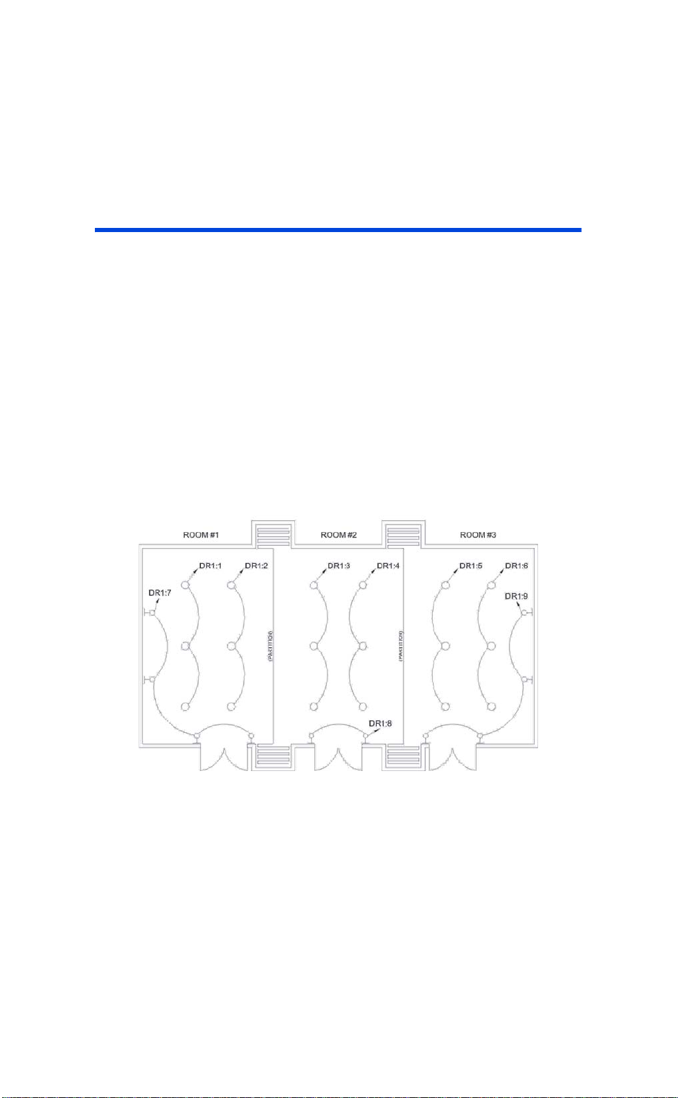
For example, consider the following lighting layout in a room:
Now consider the following lighting groups:
Page 50
Figure 15: Typical Room with Two Partitions
This hypothetical large room can be split into three smaller rooms
by closing the partitions. Lighting circuits 1,2,3,4,5 and 6, all are
connected to down lights which are designed for general room
lighting. The wall sconces, connected to circuits 7, 8, & 9 are
Page 52
User Guide
designed to warm up the walls a little bit and contribute to the
visual aesthetics of the room.
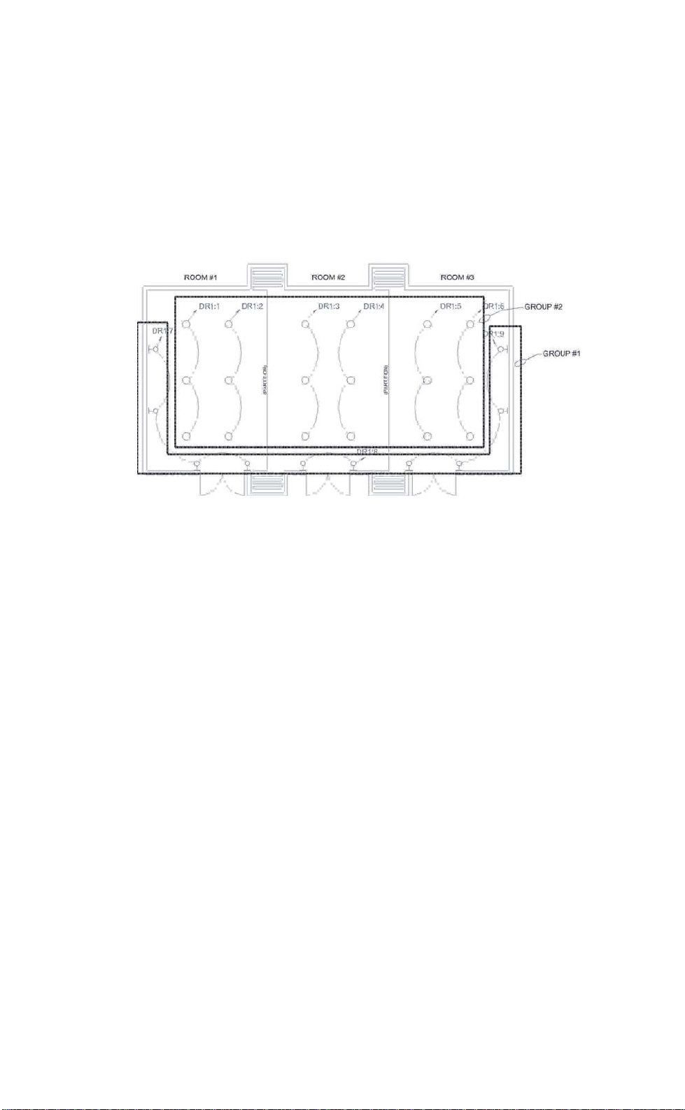
Figure 16: Grouping of Control Channels
This group as illustrated in the figure above groups all of the down
lights together into group #2 and all of the wall sconces together in
group #1. The implication of this is that when the NPC is
configured with this grouping, and the room is configured as a
large room, any changes to any channel with
group #1
will
automatically be transferred to all other channels within the same
group. The same is true for
group #2
.
Rev: A20031222.sw3.10 Page 51
Page 53
User Guide
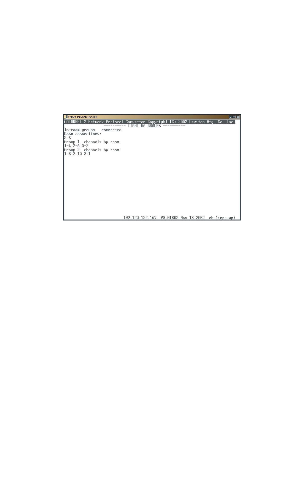
When entered into the NPC, the groups which would achieve the
desired result would be as follows:
Figure 17: Lighting Groups
To add, edit, modify, connected, or separate groups, use press the
[SELECT] button to bring up the menu which will give you the
following choices:
Page 52
Exit – returns you to the main menu
Connect rooms – allows you to select two rooms to connect
Separate rooms – allows you to select two rooms to separate
Add channels – allows you to add channels into a group
Delete channels – allows you to remove channels from a group
Show – shows you the current groupings (returns to the Lighting
Groups screen)
Procedure for Creating a group:
Step 1 Press [SELECT] to bring up the menu.
Step 2 Press [UP][DOWN] until "Add Channels" is
selected.
Step 3 Press [SELECT].
Step 4 Enter Group Number.
Page 54

User Guide
Step 5 Press [DOWN].
Step 6 Enter Room Number.
Step 7 Press [DOWN].
Step 8 Enter Channel Number.
Step 9 Press [DOWN].
Step 10 Repeat steps 1-9 for all required groups,
rooms and channels.
Step 11 Select "exit" from the menu.
Step 12 Press [SELECT] a second time to save
changes.
If Luma-Net Network Broadcast is enabled, all room numbers in
a facility must be unique.
Rev: A20031222.sw3.10 Page 53
Page 55
User Guide
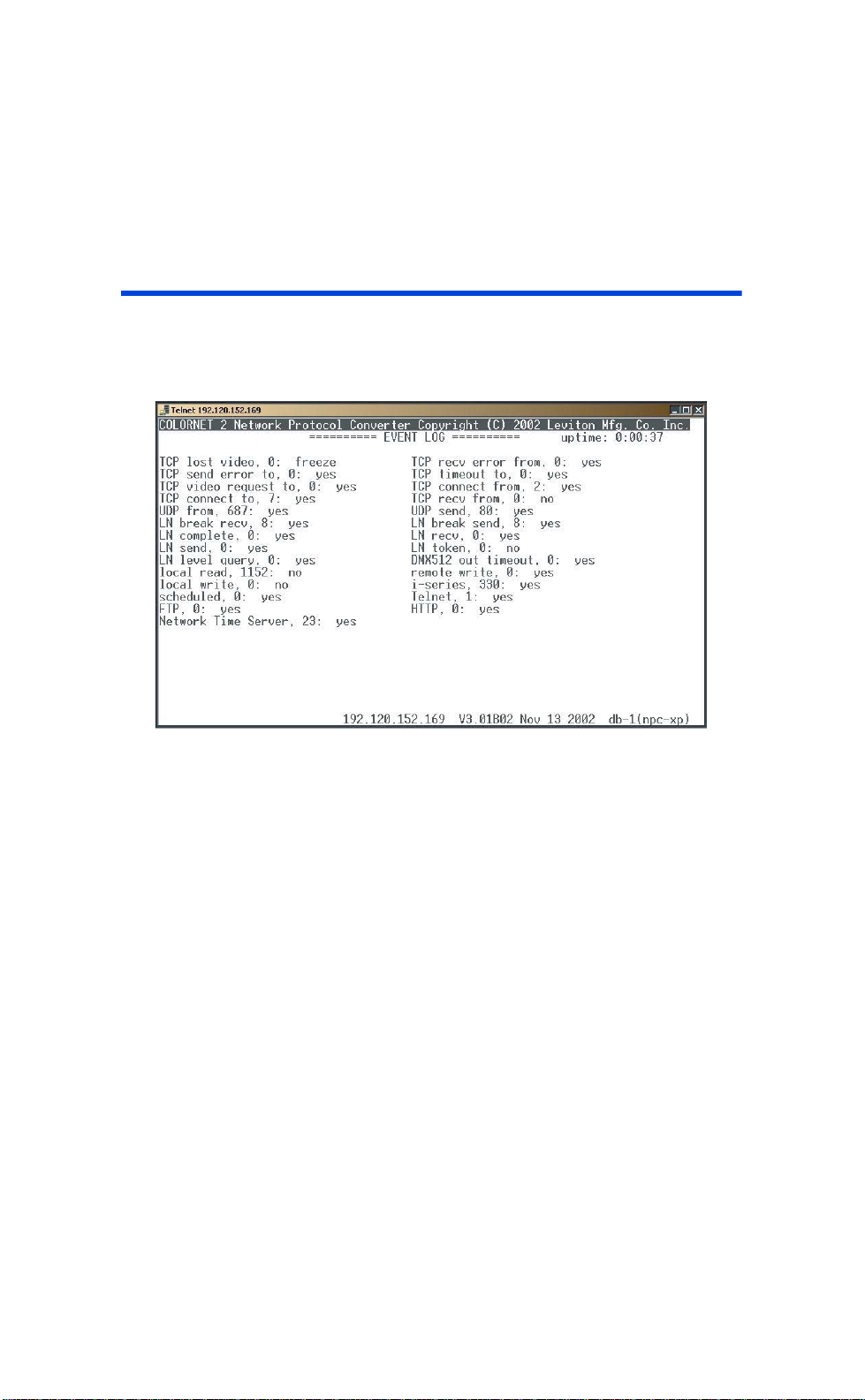
Event Log
The event log is for use by authorized factory technicians or as
directed by technical support, when troubleshooting NPC operation.
Page 54
Figure 18: Event Log
Page 56
User Guide
Selecting Displays
This section addresses the following menu options:
• Select Video 1 Display
• Select Video 2 Display
• Select Telnet Display
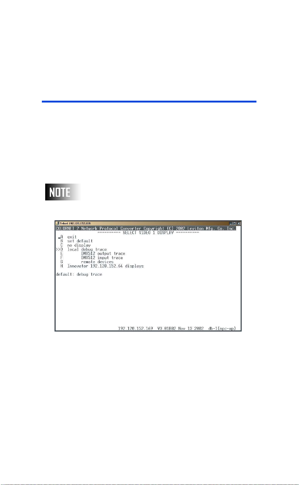
The result of these settings is the determination of what is
displayed on each of the two video outputs, or remotely on the
Telnet display.
The display selection will not become active until the exit
option is selected from the display menu.
Figure 19: Select Video 1 Display
The currently selected option is shown by a ‘>>’ adjacent to the
selection.
Rev: A20031222.sw3.10 Page 55
Page 57

User Guide
Available Options:
Exit- Exits the select video display menu and actives
the selected display.
Set Default and Exit- Used to set the video setting
selected and marked on the display with a >> to the
power up default setting and the screen the NPC
returns to.
Local Debug Trace- Displays codes used to debug
NPC unit.
DMX 512 Output Trace- Displays intensity
information for the particular DMX output.
DMX 512 Input Trace- Used to display intensity
information for the particular DMX input.
Remote Devices- Displays a list of all remote devices
currently sensed on network with IP address.
Innovator X.X.X.X. Displays- Displays any available
displays from any detected consoles. If available and
once selected a menu list would appear with options
for the type of display to assign.
iSeries Feedback Displays- Displays feedback from
a selected iSeries Dimmer Rack.
There’s a menu line for each local video, and one for Telnet if this is
active. What i Series and Innovator displays are available depends
of course on the actual network connections.
Page 56
Figure 24 shows also that the NPC is communicating with an
Innovator console and that the "STAGE" display is selected.
When the user exits the main menu, the Innovator's Stage
Display will appear on the video 1 display monitor. Further, this
is an active display and will show changes as they occur in real
time. Pressing [RIGHT][LEFT] when viewing innovator
display cycles through all available displays.
Page 58
User Guide
Configuration by Telnet or Keyboard
Telnet can be used to configure your NPC from any PC
anywhere on the network. These instructions are designed to
show you how to use telnet based on the Microsoft Windows
telnet client.
The following instructions and screen captures are applicable
for Windows 95/98/Me/NT4 and 2000. Minor variations may
exist in the format of the screens. For networks with routers,
you may need to contact your system administrator to insure
your workstation and the NPC are able to connect.
Starting the TELNET Client
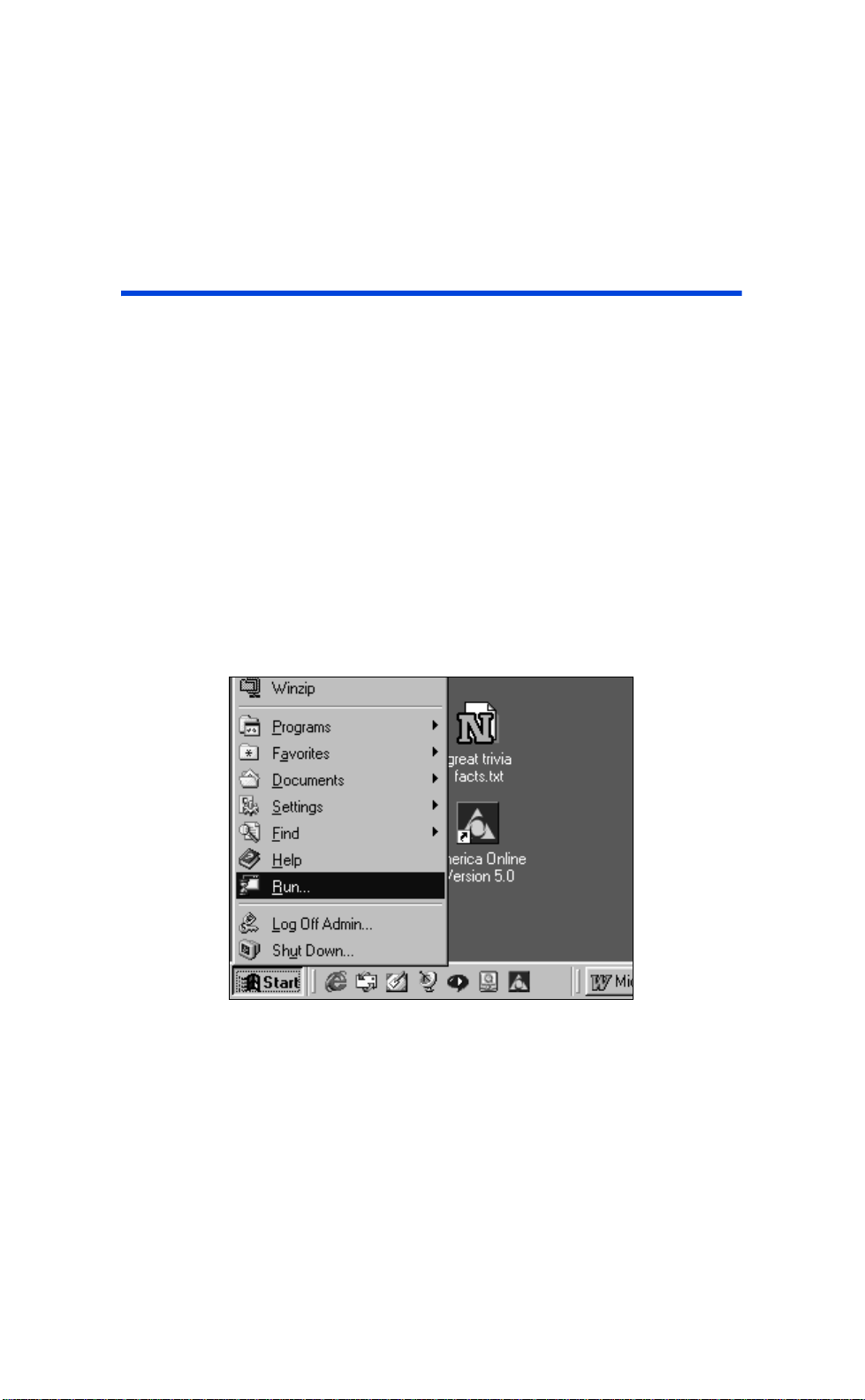
Figure 20: Windows Start Menu
Microsoft, beginning with Windows 95 included a TELNET client as
part of the operating system. To begin a TELNET session on your
PC, press the START button on the Taskbar and then select RUN.
Rev: A20031222.sw3.10 Page 57
Page 59
User Guide
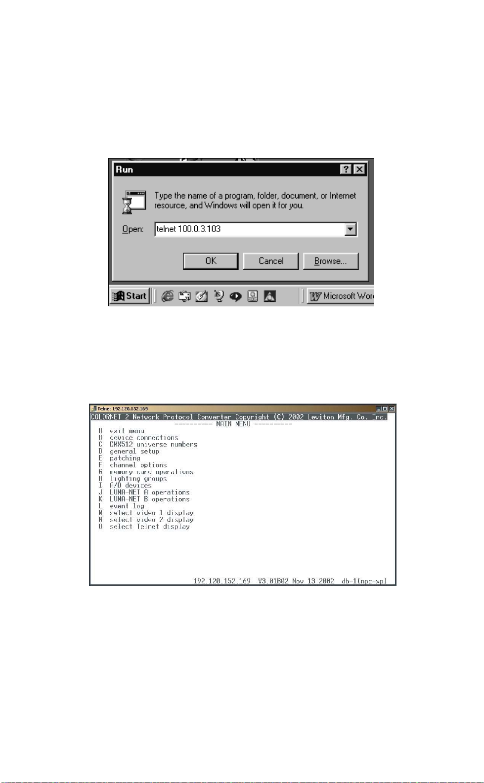
Figure 21: Typical Windows Run Dialog Box
The system will respond with a RUN dialog box. Type TELNET
followed by the IP address of the NPC you wish to send or receive
data with. Then press the ENTER key or use your mouse and click
once on the OK button.
Page 58
Figure 22: Windows Telnet Session Showing NPC Main
Menu
Page 60

User Guide
At this point, your PC will open a "Telnet" session. If you have
entered the IP address properly and the NPC is operational, it will
respond by connecting to the NPC and displaying the main menu.
The keyboard works the same way in telnet as it does when
connected to the front of an NPC-XP.
Keyboard Use
The following table shows the special keyboard functions for Telnet
and keyboard.
Front Panel Tel n e t Keyboard
Select Esc Esc
Down Cursor Down Cursor Down
Up Cursor Up Cursor Up
Next Ta b Ta b
Previous
Left Cursor Left Cursor Left
Right Cursor Right Cursor Right
Next / Prev Y Y
Next / Prev N N
Rev: A20031222.sw3.10 Page 59
Page 61

User Guide
File Transfer
There are three types of files which can be transferred to/from an
NPC:
• NPC System Software
• NPC System Configuration
• Luma-Net Device Programming
All file transfers to/from the NPC are done with an ftp client.
Code File and Configuration File
Two of the kinds of files you can transfer to and from the NPC are:
code files (extension “cod”) and configuration files (extension
“dat”), using the FTP file transfer protocol.
The code file is the application code or software that makes the
NPC operate.
The configuration file contains the entire NPC. Retrieving the file
from an NPC allows you to backup configuration transfer the same
configuration to/from multiple NPC’s or send configuration to the
factory for analysis.
The NPC knows whether to send or receive a code or configuration
by the extension of the file. If a file is sent or requested with a .cod
extension, the firmware code is sent or received. If a file is sent or
requested with a .dat, the configuration data is sent or received.
Page 60
Luma-Net Files
The last kind of file you can transfer to/from your NPC is the LumaNet configuration files. These files contain all of the programming
data contained in a Luma-Net device. The determination of which
devices programming is retrieved is determined by the name of the
file requested. The filename follows the following format:
P[port #]L[device address].lda
For example, if a device connected to port #2, or the Luma-Net B
port, with address 18 from which you wanted to retrieve
configuration, you would enter the ftp command
get P2L18.lda
Page 62
User Guide
Real World ftp Examples
The following pages will walk you through a sample ftp session.
The following instructions and screen captures are applicable
for Windows 95/98/Me/NT4 and 2000. Minor variations may
exist in the format of the screenwriter to insure your
workstation and the NPC are able to connect.
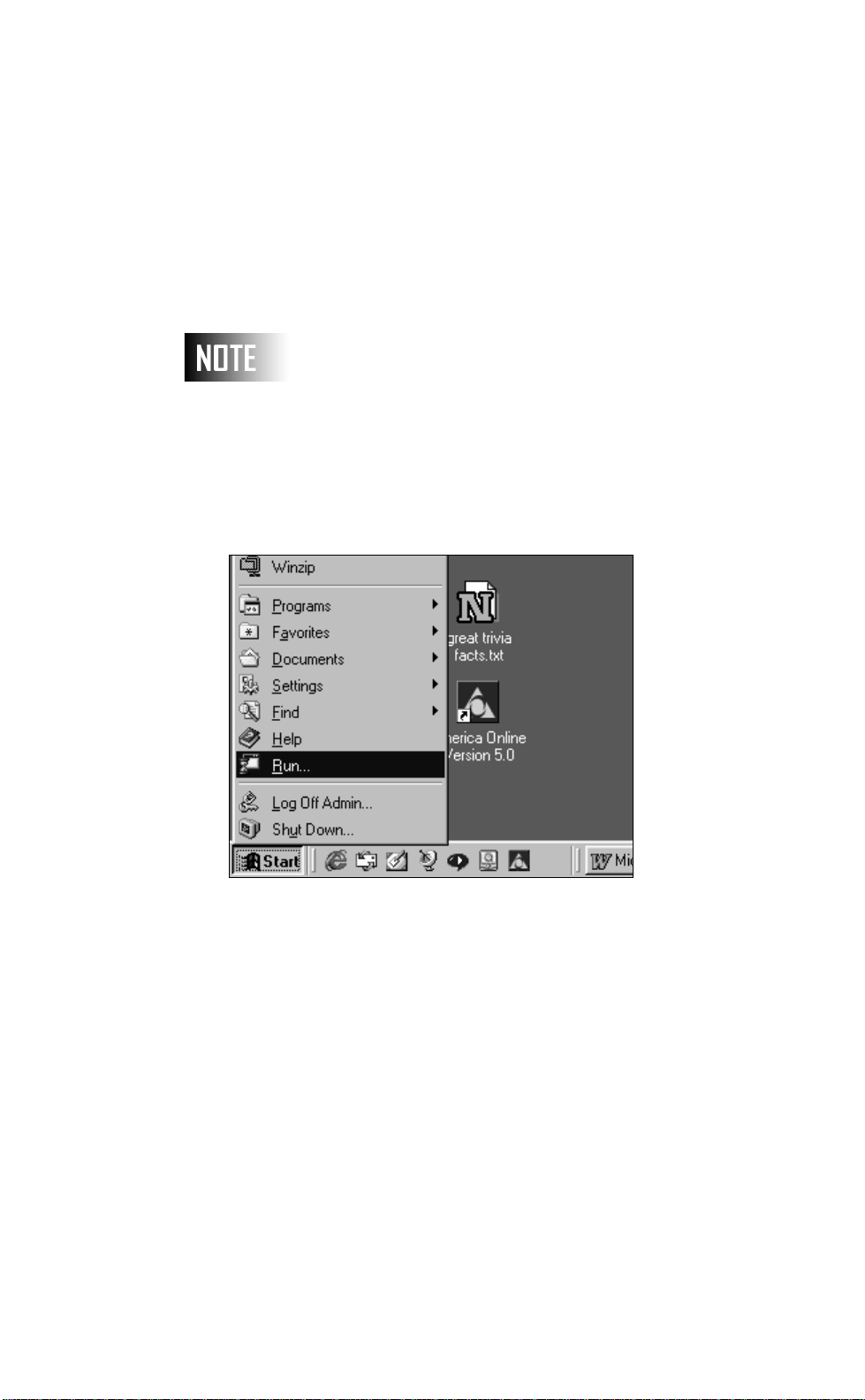
Figure 23: Windows Start Menu
To begin an FTP session on your PC, press the START button on
the task bar and then select RUN.
Rev: A20031222.sw3.10 Page 61
Page 63
User Guide
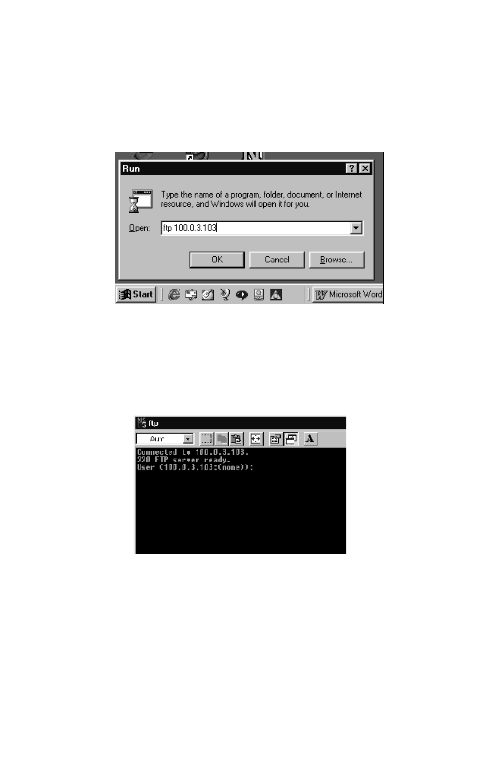
Figure 24: Windows RUN Dialog Box
The system will respond with a RUN dialog box. Type FTP followed
by the IP address of the NPC you wish to communicate with. Then
press the ENTER key or use your mouse and click once on the OK
button.
Page 62
Figure 25: WIN98 FTP Screen (Partial)
At this point, your PC will open a "dos session" or for NT systems a
"command" session. If you have entered the IP address properly
and the NPC is operational, it will respond with the above prompt
for a user name. The current user name for all NPC versions is NSI.
Page 64

User Guide
Using the FTP Client
Although FTP as a protocol supports many commands, the NPC
currently only utilizes 3 of them. They are:
Command Function
Get Retrieve configuration
(.dat) or firmware code
(.cod) from the NPC and
store it to the client’s local
disk.
p[port#]L[address].lda
Luma-Net Device Configu-
ration
Put Send to the NPC configura-
tion of firmware code from
the ftp client’s disk
Restart
Del boot
Del data restore to standard
defaults after next boot.
In the following examples, user commands are in boldface.
Start the client, log in.
Procedure:
ftp 100.1.1.61
Connected to 100.1.1.61
220 FTP server ready.
User (100.1.1.61:(none)): NSI (or your defined
password)
Rev: A20031222.sw3.10 Page 63
Page 65

User Guide
Password:
231 User name accepted.
ftp>
ftp> delete boot
Connection closed by remote host.
Retrieve the configuration file from the NPC and named confa.dat.
ftp> get confa.dat
200 OK.
150 ready to send file.
226 closing.
ftp: 11481 bytes received in 0.17 Seconds 67.54
Kbytes/sec.
ftp> quit
221 Goodbye.
Install a new application version from npc2.cod.
ftp> put npc2.cod
200 OK.
150 ready to take file.
226 closing.
ftp: 122340 bytes sent in 0.32 Seconds 382.31 Kbytes/
sec.
ftp> quit
221 Goodbye.
Page 64
The NPC will automatically initialize after this.
Get Luma-Net port A(1), station at address #2 confirmation data.
ftp> get p1l2.lda
2a OK
150 ready to send file
226 closing
Page 66

User Guide
ftp: 56 bytes sent in .08 seconds
ftp> quit
221 Goodbye
Rev: A20031222.sw3.10 Page 65
Page 67

User Guide
Warranty
Leviton Lighting Control Division of Leviton Manufacturing CO Inc.,
warrants this product to be free of material and workmanship
defects for a period of two years after system acceptance or 26
months after shipment, whichever comes first. This warranty is
limited to repair of replacement of defective equipment returned F
Freight Pre-Paid to Leviton Lighting Control Division at 20497 Teton
Ave., Tualatin, Oregon 97062, USA. User shall call 1-800-959-6004
and request a return authorization number to mark on the outside
of the returning carton, to assure that the returned material will be
properly received at Leviton. All equipment shipped back to Leviton
must be properly packed to avoid shipping damage. Replacements
or repaired equipment will be returned to sender freight prepaid,
F.O.B. factory. Leviton is not responsible for removing or replacing
equipment on the job site, and will not honor charges for such
work. Leviton will not be responsible for any loss of use time or
subsequent damages should any of the equipment fail during the
warranty period, but agrees only to repair or replace defective
equipment returned to its plant in Tualatin, Oregon. This Warranty
is void on any product that has been improperly installed,
overloaded, short circuited, abused, or altered in any manner.
Neither the seller nor Leviton shall be liable for any injury, loss or
damage, direct or consequential arising out of the use of or inability
to use the equipment. This Warranty does not cover lamps,
ballasts, and other equipment which is supplied or warranted
directly to the user by their manufacturer. Leviton makes no
warranty as to the Fitness for Purpose or other implied Warranties.
Page 66
Notice
Although the information contained within this user guide is
believed to be accurate at the time of printing, it is not guaranteed
to be without fault and is subject to change without notice. Future
software releases may change the features or operation of this
product. For current information contact:
Leviton Lighting Control Division
Technical Services
PO Box 2210
Tualatin, Oregon 97062
Voice: (800)959-6004 Fax (503)404-5601
Internet: www.colortran.com
Copyright 2003
Leviton Manufacturing Company Incorporated
All Rights Reserved.
Page 68
Leviton Lighting Control Division Headquarters
20497 SW Teton Avenue, Tualatin, OR 97062
Customer Service Telephone: 1-800-736-6682
FAX: 1-503-404-5600
Tech Line: 1-800-864-2502
Leviton Manufacturing Co., Inc.
59-25 Little Neck Parkway, Little Neck, NY 11362-2591
Telephone: 1-800-323-8920
FAX: 1-800-832-9538
Visit Leviton’s Web site at http://www.leviton.com and http://www.nsicorp.com
© 2002 Leviton Manufacturing Co., Inc. All Rights Reserved
Specifications and Pricing Subject to Change at any time.
LIT-NPDHV-000
rev: A, 12/23/2003
 Loading...