

Page 1
Daylight Harvesting Made Simple.
WEB VERSION
This user’s guide applies to the following part numbers:
Model
Number
mZb00-102
mZd20-102
mZd30-101
mZb00-C02
mZd20-C02
mZd30-C01
Description
Basic Version, 2 Zone, 2 Relay, 120V or 277V
Dimmed Version, 2 Zone, 2 Relay, 120V or 277V
Dimmed Version, 3 Zone, 1 Relay, 120V or 277V
Basic Version, 2 Zone, 2 Relay, 347V
Dimmed Version, 2 Zone, 2 Relay, 347V 2
Dimmed Version, 3 Zone, 1 Relay, 347V
0-10V
Outputs
0
2
3
0
3
Relay
Outputs
Features between models vary. As such, not all information in this manual
applies to all models.
2EVISION!
2
2
1
2
2
1
Find Quality Products Online at: [email protected]
www.GlobalTestSupply.com
Page 2

TABLE OF CONTENTS
WEB VERSION
STEP 1
STEP 2
STEP 3
STEP 4
STEP 5
STEP 6
STEP 7
PHYSICAL INSTALLATION…………………………………………..…….. 2
CONNECT LINE VOLTAGE………………………………………..………. 4
CONNECT LOW VOLTAGE……………………………………………..…. 6
CONNECT LOW VOLTAGE……………………………………………..…. 8
CONFIGURATION DIP SWITCH SETTINGS – BLOCK ONE………………. 10
CONFIGURATION DIP SWITCH SETTINGS – BLOCK TWO….…………… 12
CONFIGURATION DIP SWITCH SETTINGS – BLOCK THREE……………. 15
STEP 8
STEP 9
STEP 10
CONFIGURATION TRIM POT SETTINGS………………………………….. 16
NOTES: DAYLIGHTING CONFIGURATION………………………………… 18
NOTES: BURN IN & AUTO CAL FEATURES……………………………… 19
WARRANTY……………………………………………………………….. 20
DEFAULT TABLES…………………………………..…………………….. 23
Page 1
Find Quality Products Online at: [email protected]
www.GlobalTestSupply.com
Page 3

STEP 1
WEB VERSION
PHYSICAL INSTALLATION
MOUNTING FEATURES
The Power Pack is suitable for plenum use, indoor only, 0 - 40°C, 5 95% humidity without condensation. The supply circuit and load circuits
of the miniZ Power Pack are pre-wired to the control board. Color coded
lead wires are provided for quick connections in a junction b ox. One ½”
nipple is provided on the top of the Power Pack for this purpose.
There are three concentric knockouts provided in the Low Voltage
Compartment of the miniZ Power Pack. They are combination ½” and ¾”
knockouts. There is one on each of the three external sides of the area.
ENCLOSURE FEATURES
The enclosure of the miniZ Power Pack is divided into two compartments.
The Low Voltage Compartment is accessible through the cover-plate.
The High Voltage Compartment is factory sealed and is not accessible.
Page 2
Find Quality Products Online at: [email protected]
www.GlobalTestSupply.com
Page 4
PHYSICAL INSTALLATION
WEB VERSION
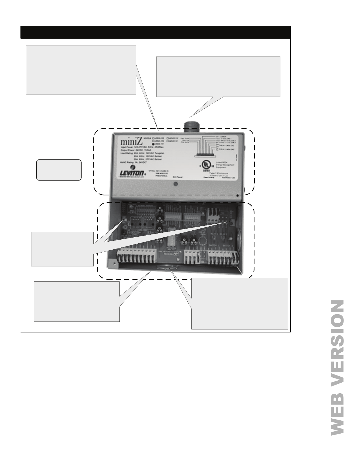
High Voltage Compartment
This area cannot be accessed in the fi eld.
Lead wires exit the compartment through
the top of the enclosure. There are leads
supplied for field connections to circuits
that energize the miniZ Power Pack and
feed the fluorescent fixture circuits.
All connections
are for copper
wire only.
Nipple
The fitting on the top of the miniZ Power Pack
attaches directly to a junction box or encl osure.
Two 0.2" mounting holes through the back of the
miniZ low voltage compartment, provide secure
fastening to any flat surface.
Mounting Holes
Two mounting holes are
provided to fasten the
miniZ Power Pack in
place.
Low Voltage Compartment
This area contains all of the low
voltage terminations required in
the field. All of the configuration
settings are made in this area
as well. Class 2 wiring only.
Knockouts
There are three concentric
knockouts provided in the Low
Voltage Compartment of the miniZ
Power Pack. They are combination
½” and ¾” knockouts. There is one
on each of the three external sides
of the area.
Page 3
Find Quality Products Online at: [email protected]
www.GlobalTestSupply.com
Page 5
CONNECT LINE VOLTAGESTEP 2
WEB VERSION
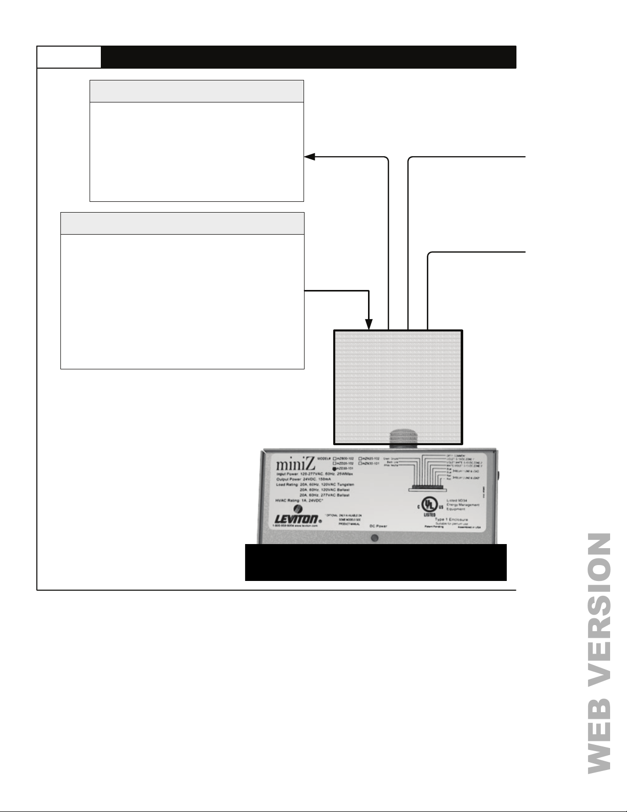
Relay 1 Line/Load
Ratings: 20A at 120VAC Tungsten/Ballast
20A at 277VAC Ballast
15A at 347VAC (347V Models Only)
Normally Open, Electrically held.
Color Code: Blue – Line, 12 AWG
Blue – Load, 12 AWG
Control Power Circuit
Voltage Rating: 120 – 277VAC, or
200-347VAC on 347V Models Only
Color Code: Black – Line, 120 – 277VAC, 18 AWG
(120-277V Models Only)
White – Neutral, 18 AWG
Orange – 347VAC, 18 AWG
(347V Models Only)
Load Rating: 10W
SUPPLY CIRCUITS
The Feed Circuit, Relay 1 Line, and
Relay 2 Line can be supplied by the
same circuit or individually. The
connections are made in the junction
box.
All supply circuits must be provided
with a 20A or less branch circuit
overcurrent protection device. Branch
circuit protection for 347V circuits
should be rated at 15A.
Page 4
JUNCTION BOX
BYOTHERS
Find Quality Products Online at: [email protected]
www.GlobalTestSupply.com
Page 6
CONNECT LINE VOLTAGE
WEB VERSION
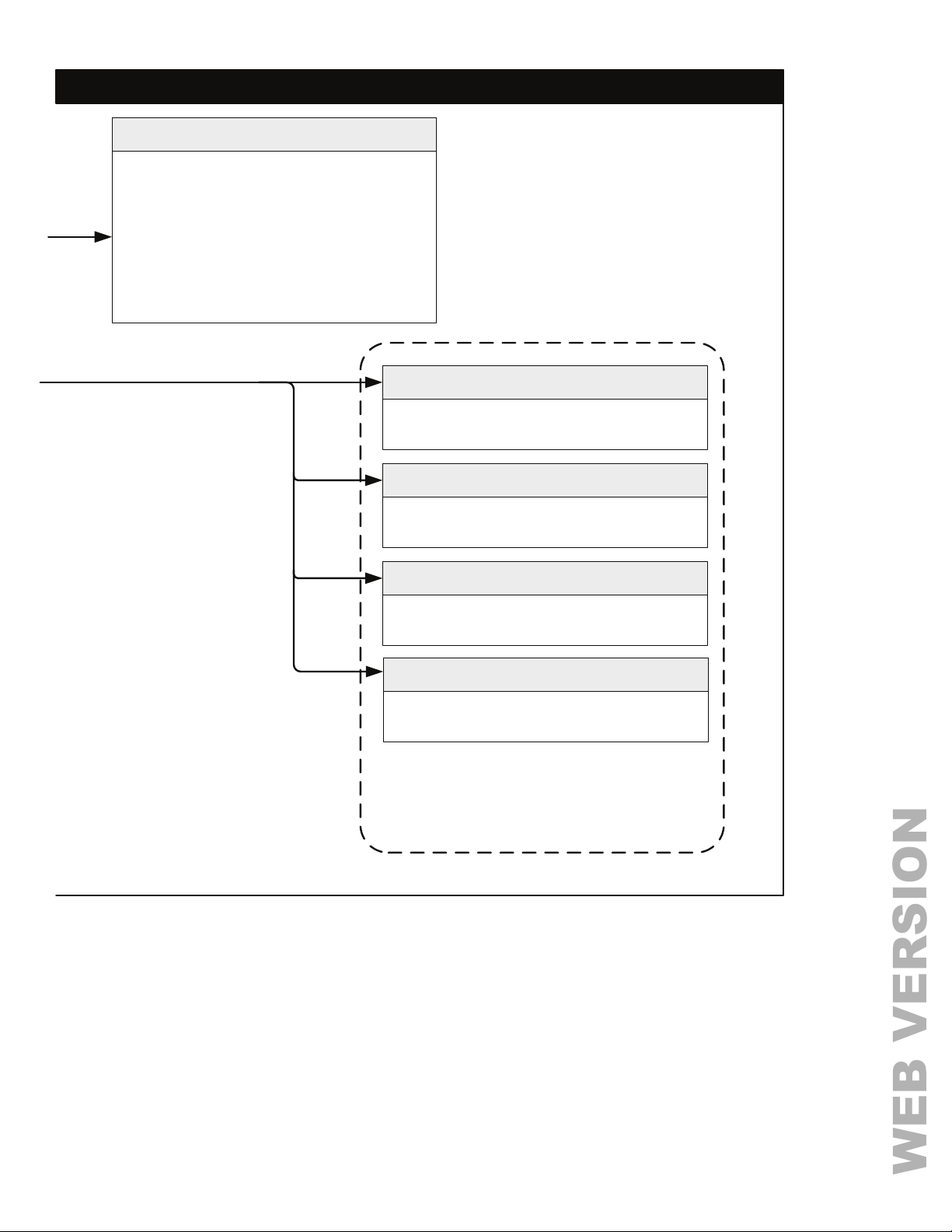
Relay 2 Line/Load
Ratings: 20A at 120VAC Tungsten/Ballast
20A at 277VAC Ballast
15A at 347VAC (347VModels Only)
Normally Open, Electrically held.
Color Code: Red – Line, 12 AWG
Red – Load, 12 AWG
Not available on three zone models.
Color Code: Gray – 22 AWG
Not available on Basic Model
Zone 1 Analog Output 0 – 10VDC
Color Code: Violet – 22 AWG
Not available on Basic Model
Zone Common
Zone 2 Analog Output 0 – 10VDC
Color Code: Violet w/White stripe – 22 AWG
Not available on Basic Model
Zone 3 Analog Output 0 – 10VDC
Color Code: White w/Violet stripe – 22 AWG
Only available on Three Zone Model
These circuits must be insulated from
the other wiring even when they are not
being used. Cap off and tape any
unused wires.
Page 5
Find Quality Products Online at: [email protected]
www.GlobalTestSupply.com
Page 7
CONNECT LOW VOLTAGESTEP 3
WEB VERSION
A
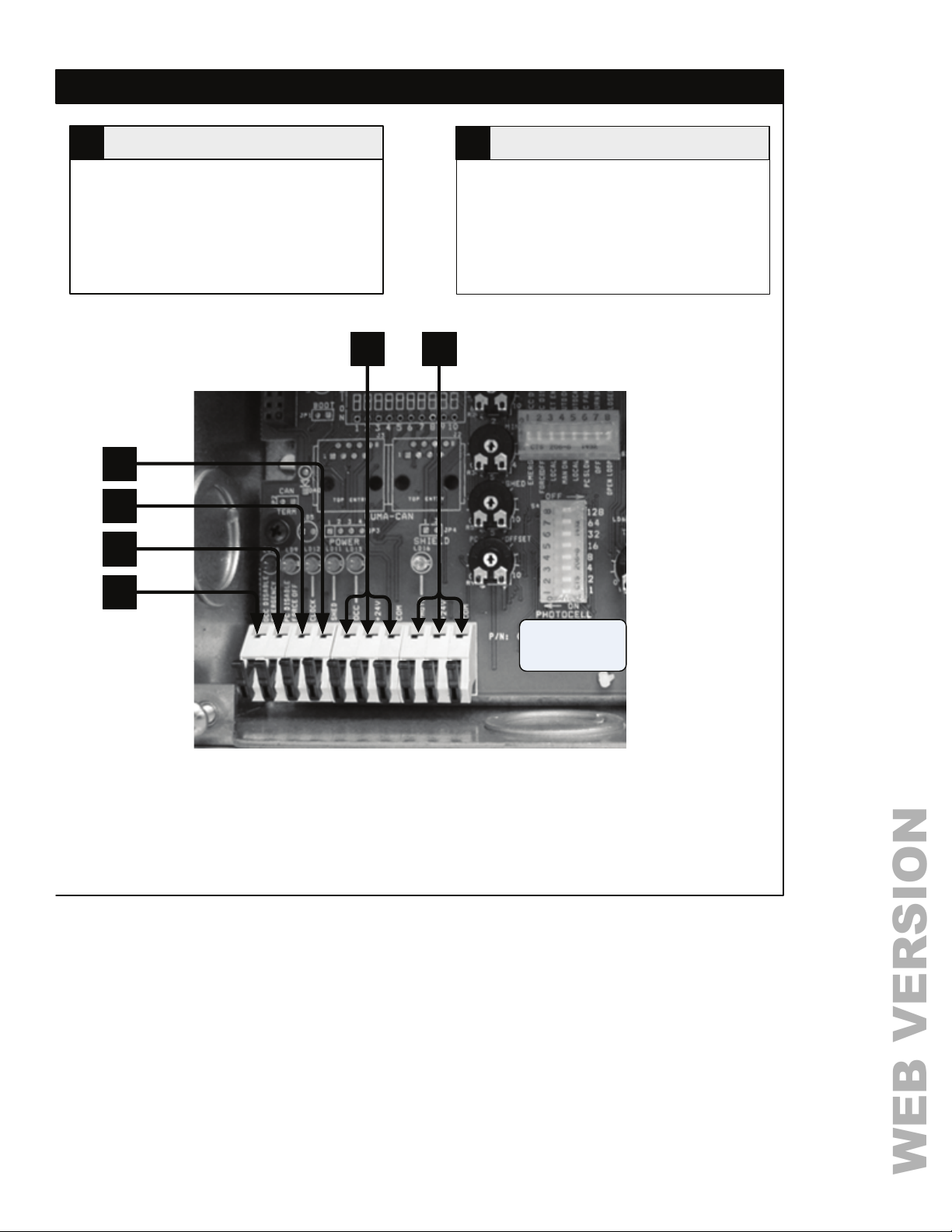
Label: OCC DISABLE / EMERGENCY
Set by DIP Switch: Block 1 Number 1
This is a +24V input signal. Function can be set to
either mode exclusively.
Occupancy Disable Mode
When the input goes high (+24V) the Power Pack
will disable the Occupancy Sensor in put and there
will be no change in the current state. When the
input signal is removed, the Occupancy Sensor will
return to the normal mode.
Emergency Mode
Emergency mode is triggered when the emergency
input is connected to the common. When the signal
is received, the Power Pack will turn on all zones
by turning on all relays and raising any 0 – 10V
outputs to 10 V. The Power Pack zones will remain
fully illuminated until the Emergency signal is
removed.
C Load Shed Input
Occupancy Sensor Disabled /
Emergency Input
Time Clock Input
Photocell Disable / Force Off Input
B
Label: PC DISABLE / FORCE OFF
Set by DIP Switch: Block 1 Number 2
This is a +24V input signal. Function can be set to
either mode exclusively.
Photocell Disable Mode
When the input goes high (+24V) the Power Pack
will disable the Photocell input, along with daylight
operation, and there will be no change in the
current state. The On switch functionality, when the
photocell is disabled, turns lights on to the
maximum level. When the input signal is removed,
the Photocell will return to the normal mode.
Force Off Mode
When the input goes high (+24V) the Power Pack
will turn off all zones. The Power Pack zones will
remain fully off until the Force Off signal is
removed.
D
Label: CLOCK
This signal will originate from a supervisory time
clock system and is a +24V input signal. When the
input goes high (+24V) the Power Pack will turn off
all zones. If the Blink Warn function has been
configured, the Power Pack will trigger the Blink
Warn cycle. If a switch is used to turn on the lights
during a period that the time clock has the lights
off, the system will go into a Blink Warn override
mode.
If both the Occupancy Sensor and the Time Clock
inputs are used, an active (+24 VDC) signal at the
Time Clock input only has the affect of changing
an Auto On configuration to a Manual On.
Page 6
Label: SHED
This signal would originate from an energy
management system and is a +24V input signal.
When the input goes high (+24V) the Power Pack
will reduce the output load levels based upon the
position of the Shed trim pot.
In the event that you are in daylighting mode and
less artificial light is required to meet the target than
is required by load shed, the lights will remain at the
lower lighting level – meeting the target.
Find Quality Products Online at: [email protected]
www.GlobalTestSupply.com
Page 8
CONNECT LOW VOLTAGE
WEB VERSION
STEP 6
Occupancy Sensor InputE
Label: OCC, +24V, COM
This three position terminal block is dedicated
to the connection of the Occupancy Sensor.
The Occupancy Sensor signal wire connects
to the OCC terminal. This +24V source is
shared with all circuits supplied from the +24V
power supply rated to a maximum of 120 mA.
E
D
C
B
A
Photocell InputF
Label: PHOTO, +24V, COM
This three terminal block is dedicated to the
connection of the Photocell. The Photocell
signal wire connects to the PHOTO terminal.
This +24V source is shared with all circuits
supplied from the +24V power supply rated to
a maximum of 120 mA.
F
All connections
are for copper
wire only.
Page 7
Find Quality Products Online at: [email protected]
www.GlobalTestSupply.com
Page 9
CONNECT LOW VOLTAGESTEP 4
WEB VERSION
Emergency / HVACG
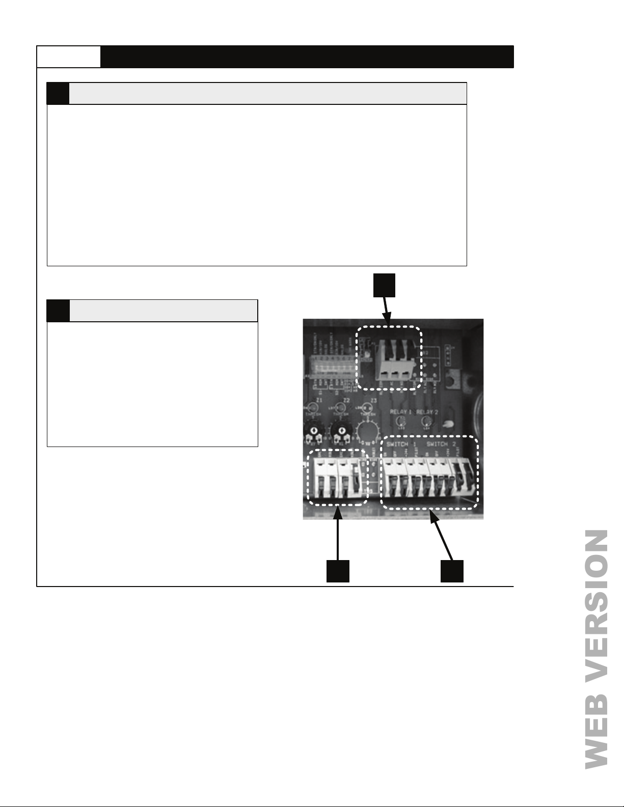
Label: RLY COM, RLY N/O, RLY N/C
There is one Low Voltage relay output rated
for 1A @ 24V which can be switched between
HVAC and Emergency output functionality.
This terminal block is connected to the
Emergency Output / HVAC relay.
Jumper Settings
A three (3) position pin header is located
adjacent to the terminal block. The jumper
configuration of this header determines the
functionality of the relay.
H
Label: GREY- Common
These terminals provide an alternate loca tion for
connecting to the dimming ballast control circuit.
There can be up to three pairs of these
terminals depending on the model of miniZ
Power Pack. The dimming circuit provides the
analog output to control up to 100 dimming
ballasts. The basic version of the miniZ Power
Pack does not have any of these terminals.
Zone Control Outputs
IOLET – Signal 0 – 10V
V
HVAC
A jumper between pins 1 and 2 will result in
HVAC functionality. In this mode the relay will
change state when the room is occupied. In
occupied state NO (normally open) contact is
closed.
Emergency
A jumper between pin 2 and 3 will result in
Emergency output functionality. In this mode
the relay will change state when an
Emergency Input signal is detected. In normal,
non-emergency state the NO (normally open)
contact is closed.
G
H I
Page 8
Find Quality Products Online at: [email protected]
www.GlobalTestSupply.com
Page 10
CONNECT LOW VOLTAGE
WEB VERSION
STEP 6
Low Voltage Switch InputsI
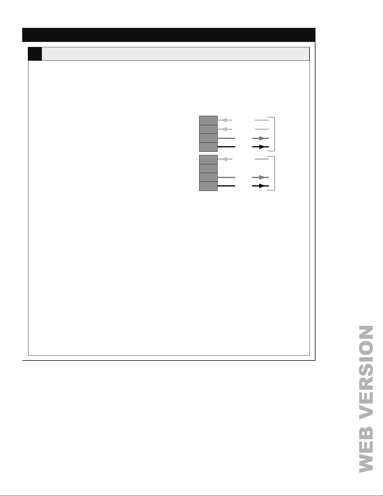
Label: SWITCH 1; ON, OFF, +24V, PILOT
SWITCH 2**; ON, OFF, +24V, PILOT
**not available on all models
There is a maximum of two low voltage switch inputs depending on the model. Switch 1 provide s control fo r
Zone 1 and Switch 2 provides control for Zone 2. There is only one Switch input for the three Zone model.
Switch Types
Set by DIP Switch: Block 2 Number 1
There are two general types of switch inputs; analog
and switched.
Analog
In analog mode, the input is expecting to see a 0 –
24 VDC or a 0 – 10 VDC signal which is used to dim
the light levels proportionately to the level of the
analog input.
Switched
In the switched mode, the input is expecting to see a
+24 VDC level to indicate that a switch is closed.
One Button Mode
The switch connected to these terminal blocks uses
the same button to turn on and turn off the lights.
Push the button once to turn on, push the button a
second time to turn off. The button signal wire should
be connected to the On terminal. No wire is required
at the Off terminal.
Two Button Mode
The switch connected to these terminal blocks uses
two different buttons to turn on and turn off the
lights. Push one button to turn on, push a different
button to turn off. The signal wires from each of the
buttons should be connected to their associated
terminals.
Supply
The +24V source terminal supplies the power
required to energize the Low Voltage switch circuit.
This source is shared with all circuits supp lied from
the +24V power supply to a maximum of 120 mA.
On
Off
+24V
Pilot
On
Off
+24V
Pilot
LOW VOLTAGE SWITCH CONNECTIONS
Signal
Signal
+24V
LED
Signal
+24V
LED
To Two
Button Low
Voltage
Switch
To One
Button Low
Voltage
Switch
Switch Connections
For a complete description of switch behaviors refer
to the Settings section. Wiring of the Low Voltage
switch must match the manufacturer
recommendations.
Pilot
This is the Pilot light output. To illuminate the button
on the Low Voltage switch, connect the appropriate
wire from the switch to the Pilot terminal. If the button
does not require illumination no wire will be present.
The Pilot output connects to common to turn on the
pilot light in your control device.
Page 9
Find Quality Products Online at: [email protected]
www.GlobalTestSupply.com
Page 11

STEP 5
WEB VERSION
CONFIGURATION DIP SWITCH SETTINGS – BLOCK ONE
Emergency / Occupancy Sensor Disable
DIP Switch: Block 1 Switch 1
Label: EMERG / OCC DISABLE
This configures the response to a signal (+24V) at the OCC Disable/Emergency input terminal. If the switch
is in the off position (EMERG), the response to a connection to common will be to turn all relays on and raise
all 0 – 10V outputs to ten volts. During this condition no other control will have any effect over the outputs. If
this switch is set to on (OCC DISABLE), the Occupancy Sensor will be disabled and no change in the
current zone state will occur when +24VDC is received by the input. When the signal is removed, the Power
Pack will return to normal operation.
Force Off / Photocell Disable
DIP Switch: Block 1 Switch 2
Label: F
This configures the response to a signal (+24V) at the PC Disable/Force Off input terminal. If the sw itch is in
the off position, the response will be to turn all zones off by turning all relays off and lowering any 0 – 10V
outputs to zero volts. If the setting is on, a signal (+24V) will disable the Photocell allowing normal operation.
The load shed function, however, will be disabl ed. When th e signa l is removed , th e Powe r Pack will re tu rn to
normal operation.
ORCE OFF / PC DISABLE
Local / Network Enabled
DIP Switch: Block 1 Switch 3
Label: LOCAL / NET ENABLED
The models covered by this manual do not have network capability. This switch should remain in the off
position.
Manual On / Auto On
DIP Switch: Block 1 Switch 4
Label: M
This switch determines the response to the Occupancy Sensor and the Time Clock signals. In the off
position (MANUAL ON) the Power Pack will turn on zones only with a switch input and the Occupancy Sensor
or the Time Clock input signal will turn the lights off. When in Manual On mode, if the lights are turned off by
the Occupancy Sensor input signal, there is a 30 second grace period in which detected movement will turn
them back on. The lights will turn on only by the MANUAL ON switch, not by the occupancy sensor.
With this switch In the on (AUTO ON) position the Power Pack will turn on and off zones in response to
signals from the Occupancy Sensor or the Time Clock inputs.
If both the Occupancy Sensor and the Time Clock inputs are used, an active (+24 VDC) signal at the Time
Clock input only has the affect of changing an Auto On configuration to a Manual On.
Page 10
AN ON / AUTO ON
Find Quality Products Online at: [email protected]
www.GlobalTestSupply.com
Page 12
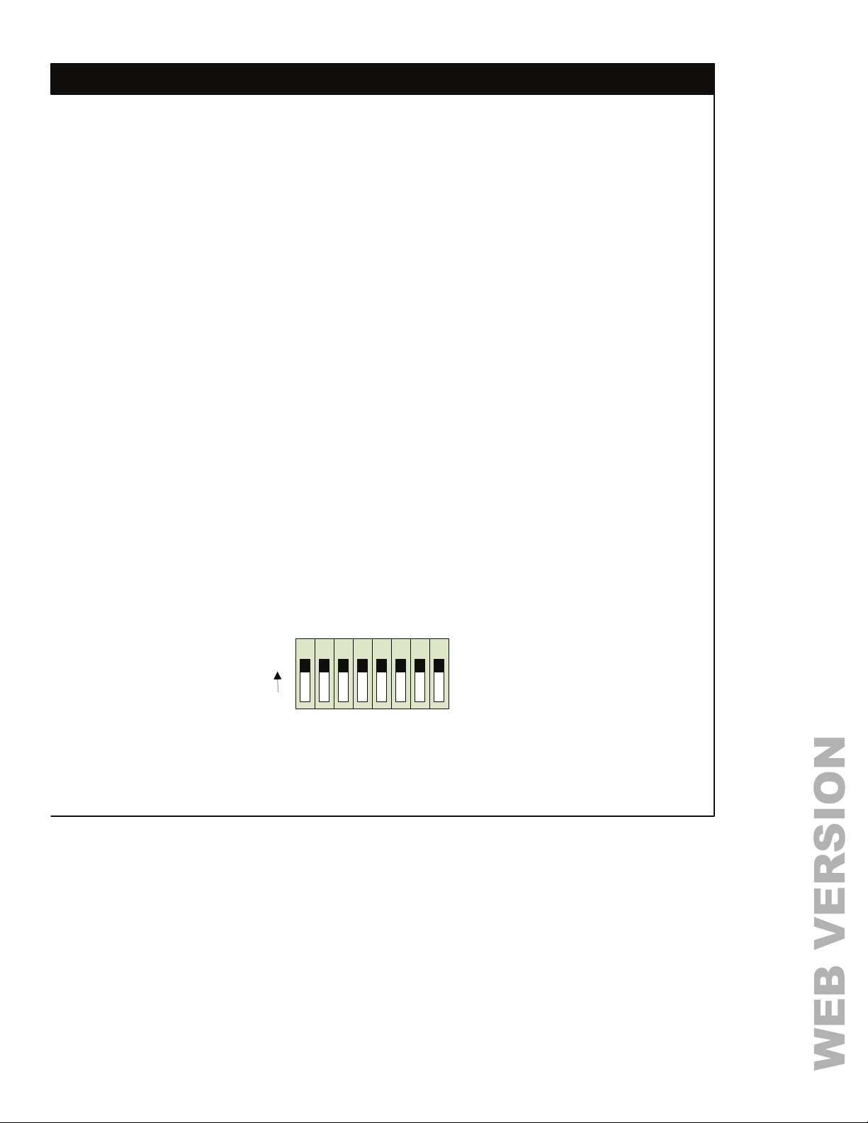
CONFIGURATION DIP SWITCH SETTINGS – BLOCK ONE
WEB VERSION
STEP 6
Local / Auto Cal
DIP Switch: Block 1 Switch 5
Label: L
The setting activates the Auto Calibration cycle. For more information, see the discussion on the Auto
Calibration feature on page 21.
OCAL / AUTO CAL
Photocell Slow Response / Fast Response
DIP Switch: Block 1 Switch 6
Label: PC SLOW / PC FAST
This setting determines the speed at which the system will respond to changes in light levels detected by
the Photocell. In the off position (PC Slow), the response time will be 30 minutes. In the on position (PC
Fast), the response time will be 30 seconds.
Burn In
DIP Switch: Block 1 Switch 7
Label: BURN IN / OFF
This setting activates the Burn In feature. Lamp burn in may be desired for new fluorescent lamps. This
feature keeps lamps from dimming for a period of 100 run hours.
Open Loop / Closed Loop
DIP Switch: Block 1 Switch 8
Label: OPEN LOOP / CLOSED LOOP
The switch determines whether the power pack should operate in open loop or closed loop daylight
harvesting mode. In closed loop mode, the photocell should be sensing the amount of ambient or task
light in the room. In open loop mode, the photocell should be sensing the amount of light coming in
through the skylight or windows. For details on the two methods of operation, please see the discussion
on page 20.
AUTO CAL
AUTO ON
NET ENABLED
OCC DISABLE
PC DISABLE
12345678
ON
LOCAL
EMERG
FORCE OFF
DIP SWITCHES
(SWITCHES SHOWN IN THE ON POSITION – REFER TO PAGE 23 FOR DEFAULT SETTINGS)
LOCAL
MAN ON
PC FAST
PC SLOW
BURN IN
OFF
CLOSED LOOP
Block 1
OPEN LOOP
Page 11
Find Quality Products Online at: [email protected]
www.GlobalTestSupply.com
Page 13
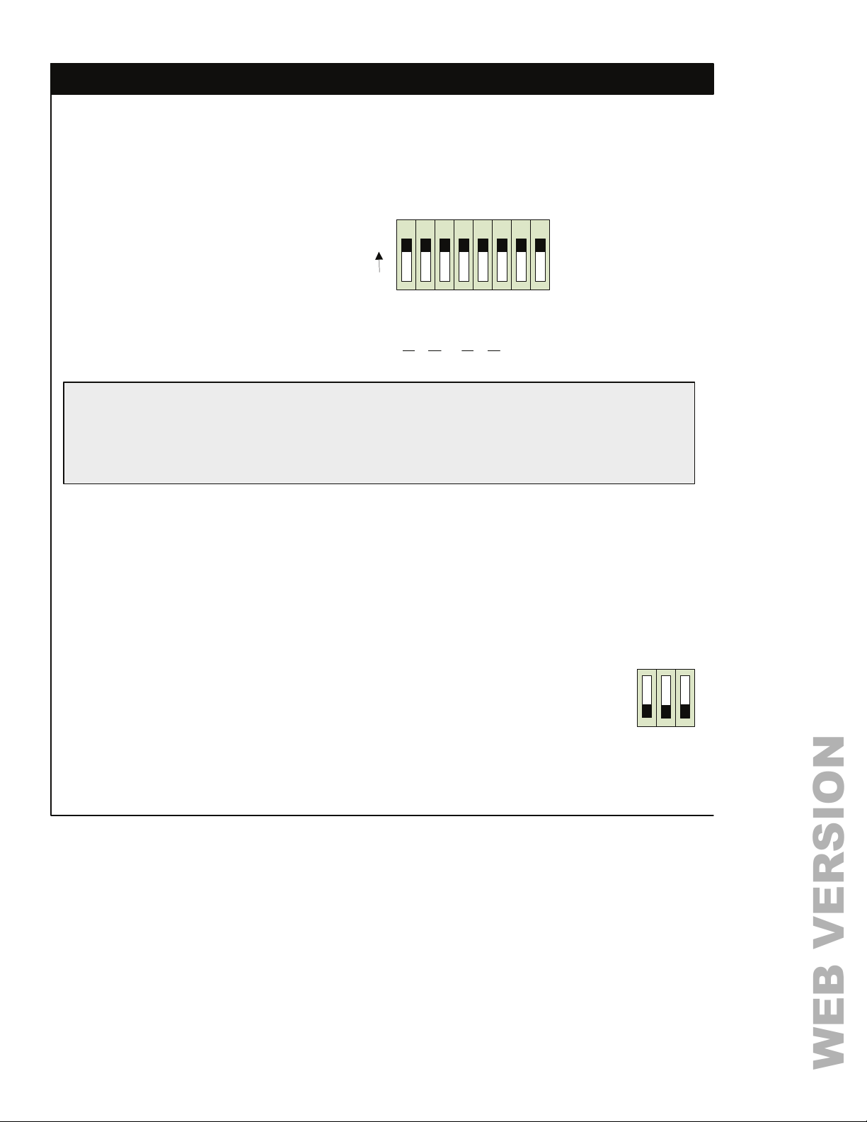
STEP 6
WEB VERSION
CONFIGURATION DIP SWITCH SETTINGS – BLOCK TWO
2 BTN/ON ONLY
MAIN/10V
ANALOG
2 BTN/ON ONLY
12345678
ON
LINK
MAIN/10V
ANALOG
B
WARN
BLOCK 2 - DIP SWITCHES
(SWITCHES SHOWN IN THE ON POSITION)
Off + Off = OFF
SWT
MOM
1 BTN
S1 S2
1 BTN
Off + On = .5 Hr
SWT
MOM
On + Off = 1 Hr
On + On = 2 Hr
SWITCH INPUT TYPES
Set by DIP Switches: Block 2 Number 3 and/or Number 6
Settings: ON = Analog, OFF = Switched
There are several modes of switch inputs; analog and switched. In analog mode there is only one
behavior. In Switch mode there are four modes of operation for input switches.
SWITCHED MODE BEHAVIOR
One Button Momentary Mode (Z-Max Low Voltage Switches)
Set by DIP Switch: Block 2 Number 1 and/or Number 4 = Off
Block 2 Number 2 and/or Number 5 = Off
Block 2 Number 3 and/or Number 6 = Off
Connections: In this mode, the ON input is used to both turn on and turn off the zone. The
switch should be wired so that the ON signal wire is landed on the ON terminal.
Dimming Unit Behavior: Activating the ON signal input with a +24 VDC level shall cause
the associated zone to fade the lights to the daylighting target level over three (3)
seconds. If daylighting is not active in the space, this function will fade the lights to the
level of the maximum trim pot. If the zone is already on, then the ligh ts will fade to off
over one (1) second. If the zone is off, tapping the button shall turn it on.
Units that have dimming available and activated shall dim the zone on and off.
Tapping the button shall fade the zone up to full in three (3) seconds. Tapping the
button shall fade the zone down to off in one (1) second. If the button is held, dimming
shall continue until either maximum or minimum is established or the button is
released. When holding the button, both up and down fade shall be three second s.
2 BTN/ON ONLY
123
456
1 BTN
MAIN/10V
or
MOM
ANALOG
SWT
Page 12
Find Quality Products Online at: [email protected]
www.GlobalTestSupply.com
Page 14
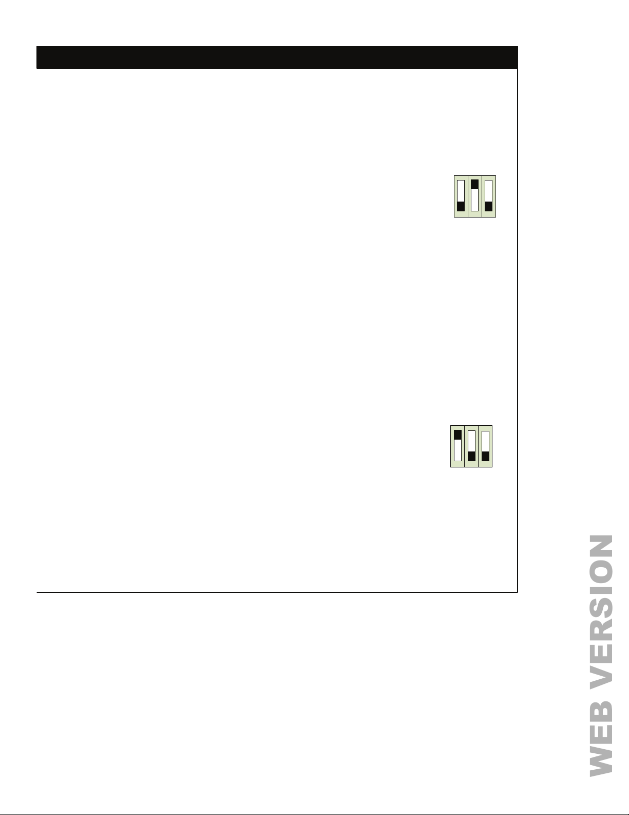
CONFIGURATION DIP SWITCH SETTINGS – BLOCK TWO
WEB VERSION
One Button Maintained Mode (Toggle Switch)
Set by DIP Switch: Block 2 Number 1 and/or Number 4 = Off
Block 2 Number 2 and/or Number 5 = On
Block 2 Number 3 and/or Number 6 = Off
Connections: In this mode, the ON input is used to both turn on and turn off the
zone. The switch should be wired so that the ON sig nal w ire is l an ded o n the ON
terminal.
Behavior: If the input is active (+24 VDC at the input), the zone is on, if it is inactive (0
VDC), the zone is off.
Units that have dimming available and activated shall dim the zone on and off.
Activating the input shall fade the zone up to full i n three (3) seconds. Activating
the input shall fade the zone down to off in one (1) second.
Two Button Mode (GE Switches, Leviton LV240 Switches)
Set by DIP Switch: Block 2 Number 1 and/or Number 4
Settings: ON
Connections: In this mode the switch sh ould be wired so that the ON signal w ire is landed on
the ON terminal. The OFF signal wire should be connected to the OFF terminal. The
switch common will be fed from the +24 VDC terminal. Activating the ON signal input with
a +24 VDC level shall cause the associated zone to turn on. Activating the OFF button
input shall turn the zone off.
Behavior: Tapping the ON button shall fade the lig hts to the daylighting level over three (3)
seconds. If daylighting is not active in the space, the ON button fades the levels to the
level of the maximum trim pot. Tapping the OFF button shall fade to off the lighting in the
zone over one (1) second. If either button is held, dimming shall continue until either
maximum or minimum is established or the button is released. While held, dimming is
three (3) seconds in both directions.
STEP 6
2 BTN/ON ONLY
MAIN/10V
123
or
456
MOM
1 BTN
2 BTN/ON ONLY
MAIN/10V
ANALOG
123
or
456
ANALOG
SWT
Two Button Mode (On Only)
Set by DIP Switch: Block 2 Number 1 and/or Number 4
Settings: ON
Connections: In this mode the switch sh ould be wired so that the ON signal w ire is landed on
the ON terminal. The OFF signal wire should not be connected. The switch common will
be fed from the +24 VDC terminal. Activating the ON signal input with a +24 VDC level
shall cause the associated zone to turn on.
Behavior: There are some cases when it is desirabl e to allow zon es to be turned on manually,
but not off. The off function is controlled by an occupancy sensor or time clock. This is
accomplished by configuring the input in two button mode and only using the ON input.
MOM
1 BTN
Page 13
SWT
Find Quality Products Online at: [email protected]
www.GlobalTestSupply.com
Page 15

STEP 6 CONFIGURATION DIP SWITCH SETTINGS – BLOCK TWO
WEB VERSION
Special Function Leviton Switches
(LV200, LV220, LV221, and LV240)
Set by DIP Switch: Block 2 Number 1 & 2 or Number
4 & 5
Settings: ON
Connections: In this mode the switches should be
wired so that the ON, OFF, PILOT, +24V, and
COM wires are connected.
On
Off
+24V
Pilot
On
Off
+24V
Pilot
LOW VOLTAGE SWITCH CONNECTIONS
Signal
Signal
+24V
LED
Signal
+24V
LED
To Two
Button Low
Voltage
Switch
To One
Button Low
Voltage
Switch
2 BTN/ON
MAIN/10V
ANALOG
123
or
456
SWT
MOM
1 BTN
LV200, LV220,
LV240
2 BTN/ON
MAIN/10V
ANALOG
123
or
456
SWT
MOM
1 BTN
LV221
BLINK WARN OVERRIDE TIME
Set by DIP Switch: Block 2 Number 7
Block 2 Number 8
Behavior: This setting determines the length of time the
zones will remain on once the blink warn feature is
activated and a request for the override has been
received. This request can be made by pressing the On
button at the low voltage switch. Pilot output will flash on
and off to indicate blink warn is active. Overriding blink
warn by tapping the On button will stop the flashing.
Page 14
BLINK
WARN
78
Off + Off = OFF
Off + On = .5 Hr
On + Off = 1 Hr
On + On = 2 Hr
Find Quality Products Online at: [email protected]
www.GlobalTestSupply.com
Page 16
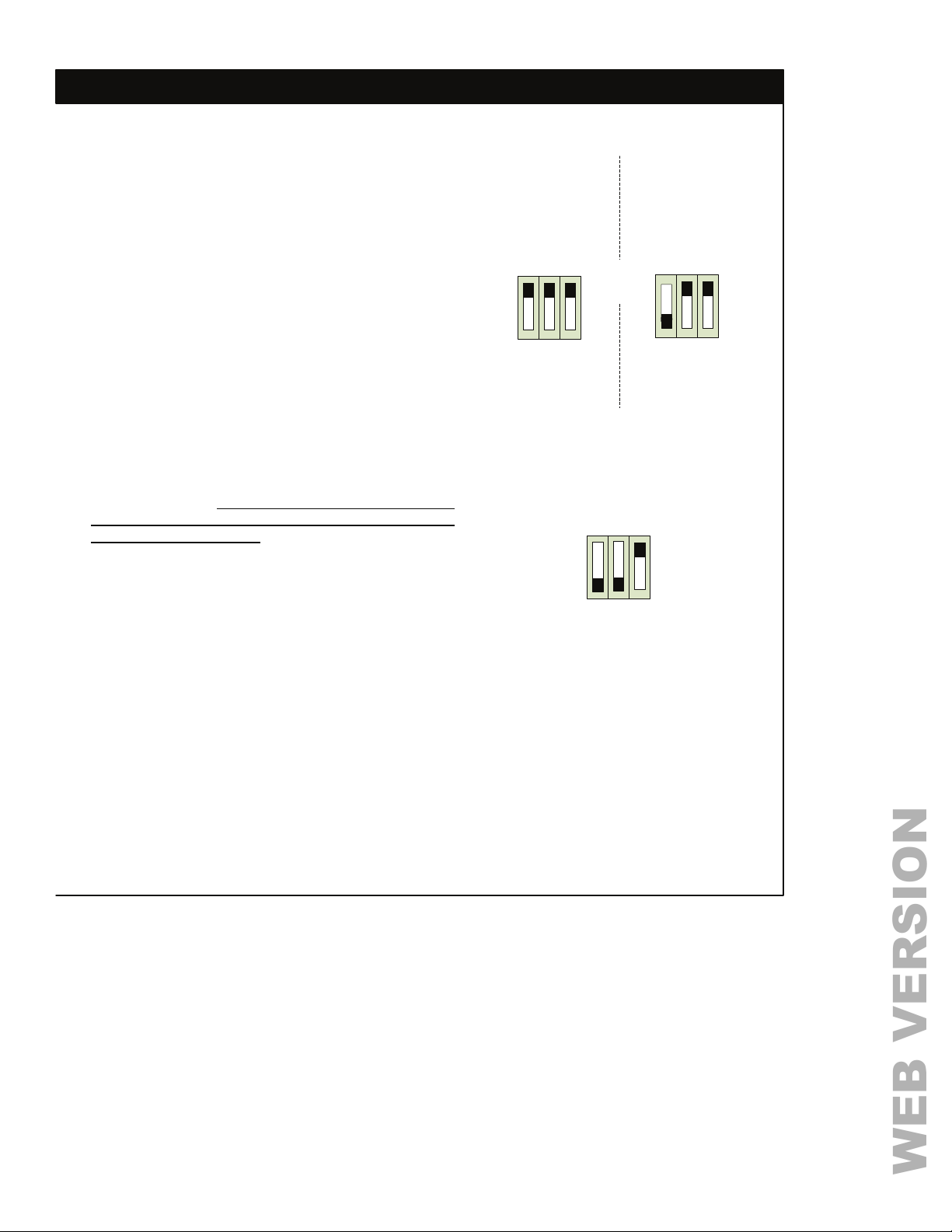
CONFIGURATION DIP SWITCH SETTINGS – BLOCK TWO
WEB VERSION
ANALOG MODE BEHAVIOR (LEVITON LV230
SWITCHES)
Set by DIP Switch: Block 2 Number 3 and/or Number 6
Settings: ON = Analog
Set by DIP Switch: Block 2 Number 2 and/or Number 5
Settings: ON = 0 – 10 VDC, OFF = 0 – 24 VDC
Connections: In this mode, the ON input is connected to +0 –
10 VDC or +0 – 24 VDC varying input. The OFF input is
connected to a maintained contact, indicating whether the
lights should be on of off. Input impedance is 85k ohms.
Behavior: Analog mode allows for a dimmed override to be
applied allowing the user to set the temporary dimmed
level of the lights via a slider or other such input device. In
this mode, the miniZ expects either +0 – 10 VDC or +0 –
24 VDC at the ON input, which indicates the dimmed level,
and a maintained input to the OFF terminal indicating
whether the lights should be on or off. When using the
miniZ in a daylighting operation, the dimmed level is a
temporary override. After the override time (60 minutes)
has elapsed, the device will automatically return to
daylight harvesting mode.
The input can be set for two different voltage ranges.
When in this mode, a 0 VDC level signal represents off,
while a +24 VDC (or +10 VDC) level represents full on.
The zone is dimmed proportionally between these levels.
2 BTN/ON
MAIN/10V
or
MOM
1 BTN
ANALOG
SWT
123
456
LV230 Slider
OR
2 BTN/ON
MAIN/10V
or
MOM
1 BTN
ANALOG
SWT
123
456
24V Analog
STEP 6
2 BTN/ON
MAIN/10V
ANALOG
123
or
456
SWT
MOM
1 BTN
10V Analog
Page 15
Find Quality Products Online at: [email protected]
www.GlobalTestSupply.com
Page 17
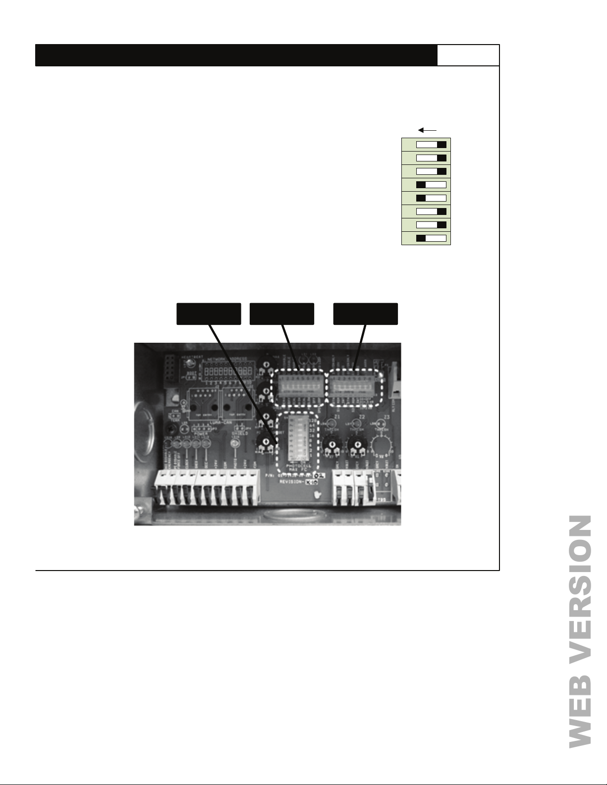
DIP Switch Block 3
WEB VERSION
Photocell Maximum Foot Candle DIP Switch
HOTOCELL MAX)
(P
Set by DIP Switch: Block 3 Number 1 to 8
Application – Open Loop Daylight Harvesting ONLY
This 8 position DIP switch is used to set the maximum foot candle
value of the photocell being used with the system. The switches shall
represent the binary number 0 - 255. The foot candle value is the sum
of the switch values multiplied by 10. The system can accommodate
photocells with a range of 0 to 2550 foot candles in increments of 10.
From this setting the miniZ Power Pack determines the foot candles
per volt.
Default
The default setting for this switch is 7 (0-70 foot candles).
BLOCK 3 BLOCK 1 BLOCK 2
STEP 7CONFIGURATION DIP SWITCH SETTINGS – BLOCK THREE
ON
128
64
32
16
8
4
2
12345678
Block 3
(TOTAL VALUE SHOWN IS 25)
(16+18+1 )
1
DIP S
WITCH BLOCK LOCATIONS
Page 17
Find Quality Products Online at: [email protected]
www.GlobalTestSupply.com
Page 18
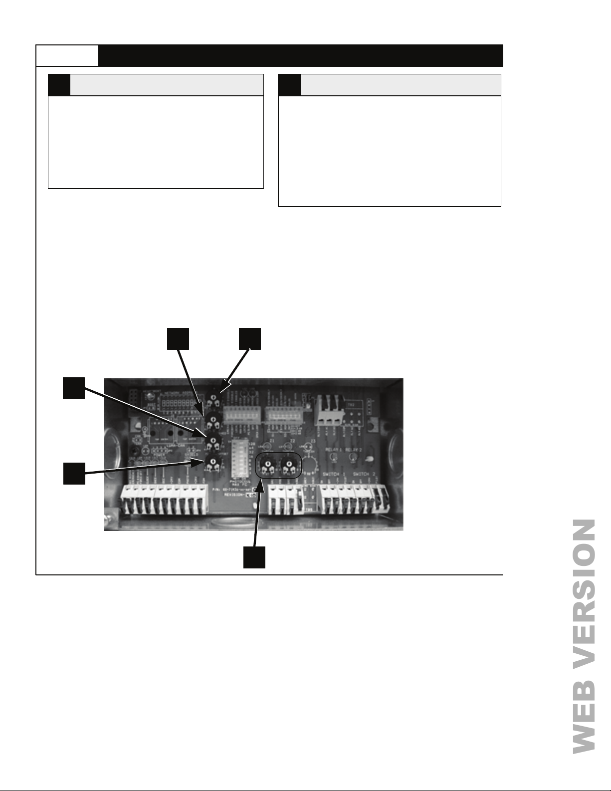
STEP 8 CONFIGURATION TRIM POT SETTINGS
WEB VERSION
MAXIMUM TRIM POT (MAX)1
Adjust this trim pot to set the upper limit for the
0 – 10 VDC Ballast outputs. The full range of the
pot adjusts the upper limit in a range from 6 volts
to 10 volts.
Default
The default position is full on (counterclockwise).
12
MINIMUM TRIM POT (MIN)2
Adjust this trim pot to set the minimum level the
0 – 10 VDC outputs will dim during daylight
harvesting mode operation. The full range of the
pot adjusts the lower limit in a range from 0 volts to
4 volts.
Default
The default position is full off (clockwise).
TRIM POT LOCATIONS
3
Page 18
4
5
Find Quality Products Online at: [email protected]
www.GlobalTestSupply.com
Page 19
CONFIGURATION TRIM POT SETTINGS
WEB VERSION
STEP 6
LOAD SHED TRIM POT (SHED)3
Adjust this trim pot to determine the action taken
when the L
Application
For the basic model, if the pot is positioned
between 0 – 30%, relay 1 will be forced off, if set
between 30 – 70%, both relays will be forced off,
and if set between 70 – 100%, relay 2 will be
forced off.
For dimmed models, all 0 – 10 VDC outputs will go
to the level determined by the position of the Load
Shed pot if it is currently higher than that level. If
the Load Shed pot is adjusted above the Max pot,
no change shall occur.
Default
The default position is center.
OAD SHED (SHED) input is active.
DAYLIGHT HARVESTING THRESHOLD
5
On dimmed models, these trim pots will be used to
determine the amount of daylight control that is
applied to each zone. The full range of rotation
represents 0 – 100% of the photocell’s foot candle
range. The procedure for adjusting these trim pots
is different depending upon whether the miniZ has
been set to operate as an open- or closed-looped
system. In open loop, if daylight harvesting is not
desired, turning the pots full (100%) shall disable
the feature and the lights on the zone will stay on
at the Max level.
In closed loop, the Threshold trim pot has the
added functionality that it can be used to exclude a
zone from dimming, as it relates to daylight
harvesting operation, by setting it to a value o f less
than 5%.
TRIM POT (THRESH)
Default
The default position is full on (clockwise).
DAYLIGHT HARVESTING OFFSET TRIM POT (OFFSET)4
Dimmed Model, Open Loop
In Open Loop mode, the Offset trim pot is used to enter the desired foot candle value from 0 – 100 foot
candles, at the photocell. A setting of 0 equals 0 foot candles, a setting of 10 equals 100 foot candles.
Dimmed Model, Closed Loop
In Closed Loop mode, the Offset trim is used to set the target photocell values. The trim pots scale of 0 – 10
represents the 0 – 10 volt signal of the photocell. If, however, you are using Auto Calibration, the Offset trim
pot defines the Light Loss Factor (LLF) applied to the target level. The LLF is 20% when the trim pot is set at 0
and 0% when the trim pot is at 10. The assumption is that auto calibration occurs when the lamps are new, the
fixtures are clean, and the room is performing to the initial lumen output not the maintained lumen output.
When the Offset trim pot is set to 0, the LLF is set to 20%. When the Offset trim pot is set to 10, the LLF is 0%.
Basic Model
On the basic model this trim pot sets the point that Rel ay 1 is opened. The photocell must remain on either
side of the trip point for the time determined by the Photocell Fast/Slow DIP switch setting before changing
states.
Page 19
Find Quality Products Online at: [email protected]
www.GlobalTestSupply.com
Page 20
STEP 9 NOTES: DAYLIGHTING CONFIGURATION
WEB VERSION
Setup
To setup your device in either open loop or closed loop mode, please reference Step 5, Settings,
found on page 11 of this document. This section details with specific calibration and configuration of
your miniZ device when in each of these modes.
Open-Loop Operation
Typical open-loop systems employ a photocell positioned towards the daylight source (window,
skylight, etc).
Important! For best results, the photocell should receive as little electric light as possible.
To determine the setting of each of the PC Level trim pots, light meter readings must be taken
during the day with the electric lights off and during consistent daylight (i.e. if a cloud covers the sun
during meter recording, start over or wait for the cloud to pass). Position the light meter at the
photocell, pointing it in the same direction as the photoc ell. Record the value. Next position the
light meter at the work surface in the room pointing it towards the ceiling. Record the value.
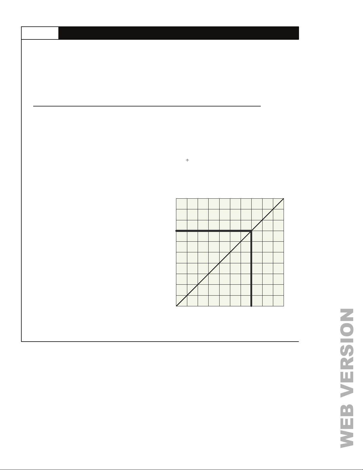
Now calculate the ratio of the zone value to the photocell value for each room. Use the chart below
to determine the PC Level setting. For ex ample, if the photocell reading is 400 foot cand les and
Zone reading is 50 foot candles, the ratio is 50/400 = 0.125 (50
chart’s x-axis (Room/Photocell Ratio) and follow a straight line up until the diagonal line it
intersected. Then follow a straight line to the left on the chart to obtain th e trim pot setting. In this
case the setting would be 7.
1.0
400 = 0.125). Find 0.125 on the
Closed-Loop Operation
Closed-loop systems position the
photocell so that it measures the amount
of light in the room being controlled. It is
important to correctly position the
photocell so that it receives either the
average amount of ambient light or if
sensing task lighting that it is directed at a
surface which will reflect an appropriate
representation of the amount of task
lighting in the room.
Page 20
.9
.8
.7
.6
.5
.4
.3
.2
Threshold Trim Pot Setting
.1
0
0.0
0.008
0.016
0.002
0.004
0.031
Room/Photocell Ratio
0.063
0.125
0.250
1.0
0.500
Find Quality Products Online at: [email protected]
www.GlobalTestSupply.com
Page 21
STEP 10NOTES: BURN IN & AUTO CAL FEATURES
WEB VERSION
BURN IN FEATURE
Set by DIP Switch: Block 1 Number 7 = ON
The Burn IN feature of the miniZ Power Pack
provides an automatic initializing cycle for new
fluorescent lamps. The Burn In feature will
maintain the fluorescent fixtures at full
illumination levels for 100 hours. At the
conclusion of the Burn IN cycle the miniZ Power
Pack will enter normal operation.
When to use it
Some manufacturers of fluorescent lamps require
the lamp to be run at the full illumination level for
a ‘burn in’ period prior to any dimming activity.
This feature provides an easy method to satisfy
that requirement.
Start
To initialize this function, move the DIP switch
labeled Burn In to the ‘ON’ position. Observe:
The LED above the DIP switch will glow red and
will remain in that state until the cycle is
complete. The fluorescent fixtures will also be
illuminated at their full level when turned on until
all zones have been on for 100 hours.
Stop
The cycle can be stopped at any time by turning
off the DIP switch.
Observe: The red LED ab ove the DIP switch will
turn off.
Restart
To restart this function, move the DIP switch
labeled Burn In to the ‘ON’ position. Observe:
The observations will be the same as the Start
step.
Burn In and the Auto Cal features can occur
at the same time.
AUTO CALIBRATION
(CLOSED LOOP OPERATION ONLY)
Set by DIP Switch: Block 1 Number 5 = On
The Auto Calibration feature of the miniZ Power
Pack provides an automatic daylight harvesting
calibration. During the 24 hour calibration
period all fluorescent fixtures will remain at
full illumination levels and cannot be turned
off. The miniZ Power Pack will monitor the
Photocell readings to determine the lowest level
during the calibration period. This reading
typically occurs at night. At the conclusion of the
Auto Calibration period the miniZ Power Pack
will enter normal operation.
Note: Auto Calibration is only applicable to
closed loop photocell operation. When the
device is configured in open loop mode, auto
calibration can be activated but the results of
such will have no effect on the configuration
or output of the miniZ.
Start
To initialize this function, move the DIP switch
labeled Auto Cal to the ‘ON’ position.
Observe: The LED above the DIP switch will
begin to flash on and off in a steady pattern until
the calibration period is complete. The
fluorescent fixtures will also be illuminated at their
full level for the duration of the cycle.
Stop
The cycle can be stopped at any time by turning
off the DIP switch.
Observe: Th e red LED above the DIP switch will
turn off.
Restart
To restart this function, move the DIP switch
labeled Auto Cal to the ‘OFF” position and then
back to the ‘ON’ position.
End of Cycle
Observe: The LED will be on steady at the end of
the calibration period and the miniZ Power Pack
will automatically enter normal operation.
Page 21
Find Quality Products Online at: [email protected]
www.GlobalTestSupply.com
Page 22

WARRANTY
WEB VERSION
LIMITED 5 YEAR WARRANTY AND EXCLUSIONS
Leviton warrants to the original consumer purchaser and not for the benefi t of an yone el se that this prod uct at
the time of its sale by Leviton is free of defects in materials and workmanship under normal and proper use
for five years from the purchase date. Leviton’s only obligation is to correct such defects by repair or
replacement, at its option, if within such five year period the product is returned prepaid, with proof
of purchase date, and a description of the problem. This warranty excludes and there is disclaimed
liability for labor for removal of this product or reinstallation. This warranty is void if this product is installed
improperly or in an improper environment, overloaded, misused, opened, abused, or altered in any
manner, or is not used under normal operating conditions or not in accordance with any labels or
instructions. There are no other or implied warranties of any kind, including merchantability and fitness for a
particular purpose, but if any implied warranty is required by the application jurisdiction, the duration of
any such implied warranty, including merchantability and fitness for a particular purpose, is limited to
five years. Leviton is not liable for incidental, indirect, special, or consequential damages, including without
limitation, damage to, or loss of use of, any equipment, lots sales or profits of delay or failure to
perform this warranty obligation. The remedies provide herein are the exclusive remedies under this
warranty, whether based on contract, tort or otherwise.
Page 22
WARNING: TO BE INSTALLED AND/OR USED IN ACCORDANCE WITH
APPROPRIATE ELECTRICAL CODES AND REGULATIONS.
WARNING: IF YOU ARE UNSURE ABOUT ANY OF THESE
INSTRUCTIONS, CONSULT A QUALIFIED ELECTRICIAN.
CAUTION: USE THIS DEVICE ONLY WITH COPPER OR COPPER CLAD
WIRE, WITH ALUMINUM WIRE ONLY USE DEVICES MARKED CO/ALR OR
CU/AL.
WARNING: TO AVOID FIRE, SHOCK OR DEATH; TURN OFF POWER AT
CIRCUIT BREAKER OR FUSE AND TEST THAT POWER IS OFF BEFORE
WIRING!
Find Quality Products Online at: [email protected]
www.GlobalTestSupply.com
Page 23
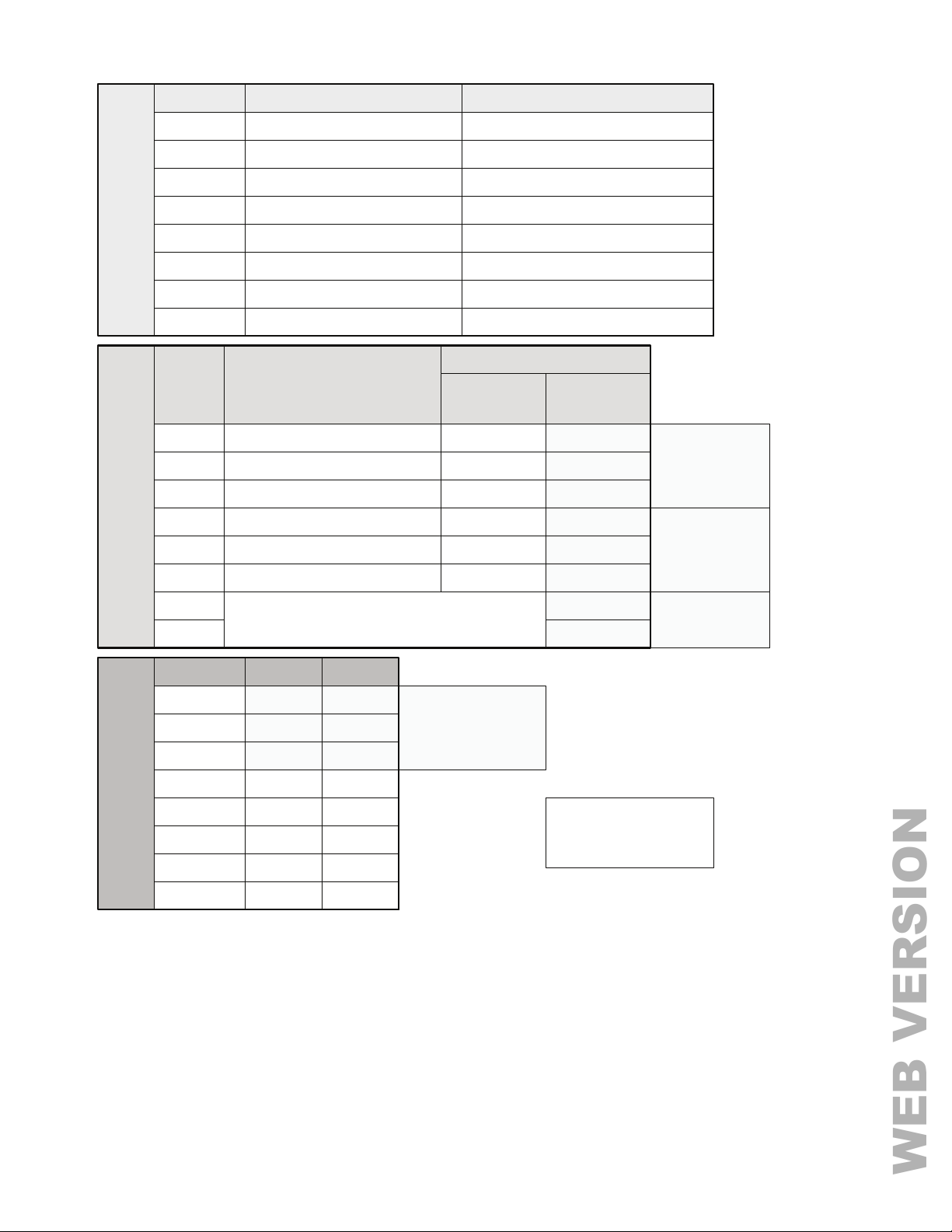
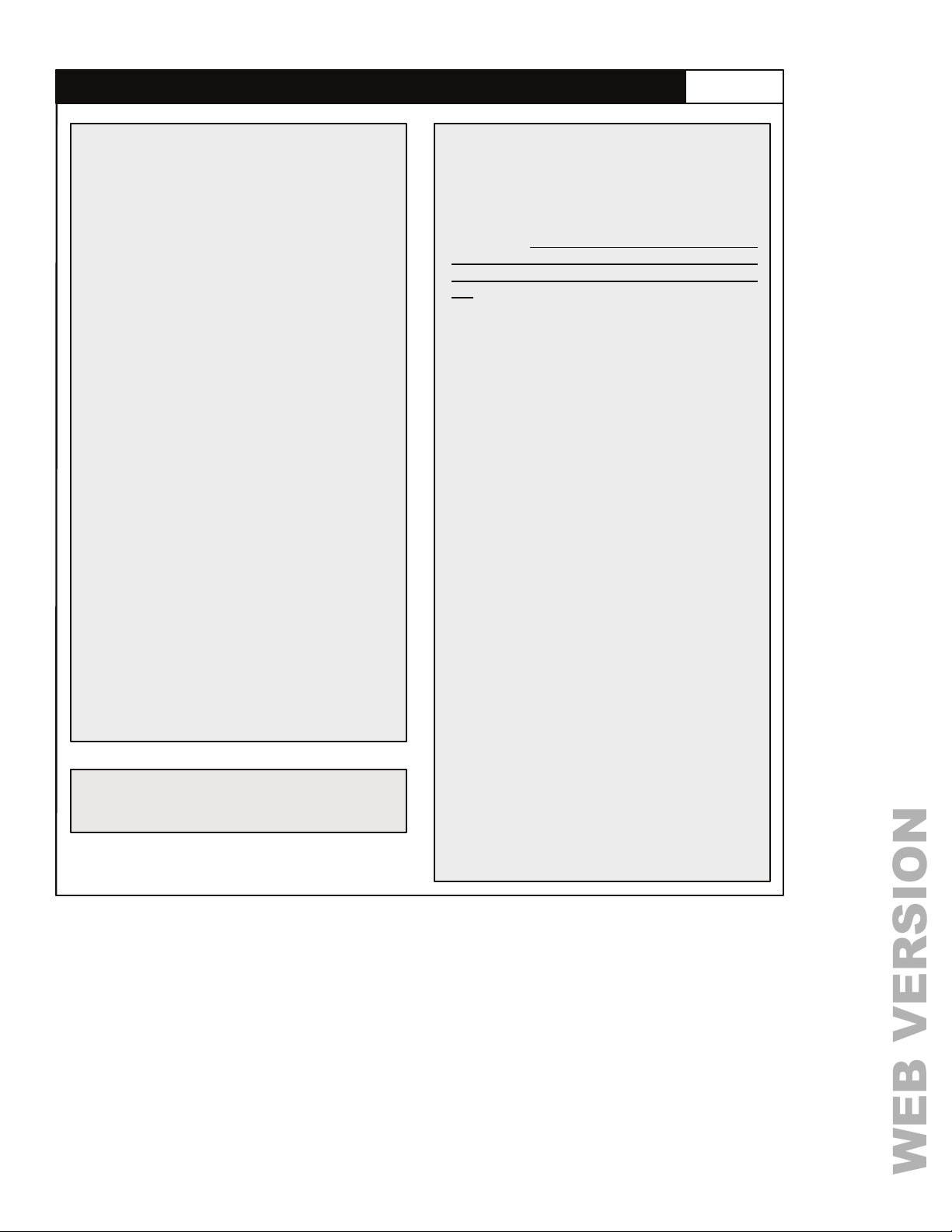
SWITCH NO. FUNCTION DEFAULT POSITION IN ALL MODELS
WEB VERSION
1 EMERG / OCC DISABLE EMERG
2 FORCE OFF / PC DISABLE FORCE OFF
3 LOCAL / NET ENABLE LOCAL
4 MAN ON / AUTO ON AUTO ON
5 LOCAL / AUTO CAL LOCAL
DIP SWITCH BANK S2
6 PC SLOW / PC FAST PC FAST
7 OFF / BURN IN OFF
8 OPEN LOOP / CLOSED LOOP CLOSED LOOP
SWITCH
NO.
1 S1 – 1 BTN / 2 BTN ON ONLY 2 BTN ON
2 S1 – MOM / MAIN 10V MOM
3 S1 – SWT / ANALOG SWT
4 S2 – 1 BTN / 2 BTN ON ONLY 2 BTN ON
5 S2 – MOM / MAIN 10V MOM
DIP SWITCH BANK S3
6 S2 – SWT / ANALOG SWT
7
ENABLES BLINK WARN & SETS OVERRIDE TIME.
00 = B
8
SWITCH NO. VALUE
1 1
2 2
3 4
DEFAULT POSITIONS
FUNCTION
W OFF, 01 = ½ HR, 10 = 1HR, 11 = 2HR.
BASIC
MODELS
POSITION
ON
ON
ON
SETUP FOR 70 FC
MAXIMUM OUTPUT
PHOTOCELL
DIMMING &
NETWORK
MODELS
2 BTN ON
MOM 10V
SWT
2 BTN ON
MOM 10V
SWT
OFF
OFF
SETUP FOR
OPERATION
LV200
WITH
OR LV240
SETUP FOR
OPERATION
LV200
WITH
OR LV240
BLINK WARN
DISABLED, 1
VERRIDE
HR O
4 8
5 16
DIP SWITCH BANK S4
HOTOCELL MAX FC (7)
P
6 32
7 64
8 128
Find Quality Products Online at: [email protected]
OFF
OFF
OFF
JUMPER PLUG JP5 –
INSTALLED FOR HVAC
(HVAC / E
OFF
OFF
www.GlobalTestSupply.com
MERG)
Page 23
Page 24
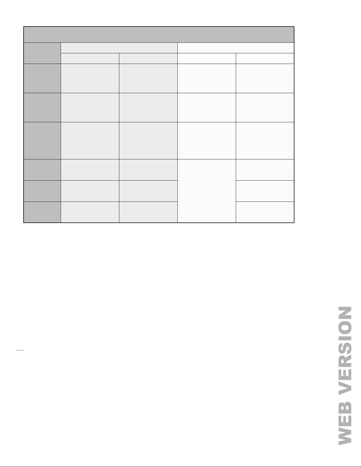
TRIM POTS
WEB VERSION
LABEL
MAX.
MIN.
PC OFFSET
THRESHOLD
1
THRESHOLD
2
THRESHOLD
3
BASIC MODEL
N/A N/A
N/A N/A
Sets the point that
Relay 1 is opened.
Range 0 – 10V.
N/A
N/A N/A
N/A N/A
DIMMING & NETWORK MODELS
DEFAULT SETTINGFUNCTION
Max output of
0 - 10V Outputs,
Range 6 - 10V.
Minimum
daylighting level,
Range 0 - 4V.
Sets target level 0 –
5 (5V)
N/A
10V in Closed Loop
mode, 0 – 100fc in
Open Loop mode.
Proportionally
scales the
daylighting level,
Range 0 – 100%
DEFAULT SETTINGFUNCTION
10 (100%)
0%
0 (20%)
10 (100%)
(CLOCKWISE)
10 (100%)
(CLOCKWISE)
10 (100%)
(CLOCKWISE)
P/N PK-93383-10-00-0B
Find Quality Products Online at: [email protected]
www.GlobalTestSupply.com
 Loading...