

Page 1
Installing and
!
LINE
ABC
LOAD
Service
Panel
LOAD
LINE
LINE
Testing a
LEV-LOKTM
Modular GFCI
Receptacle
Please read this leaflet
completely before getting started.
PK-93844-10-00-2A
CAUTION
• To prevent severe shock or
electrocution always turn the power
OFF at the service panel before
working with wiring.
• Use this GFCI with copper or
copper-clad wire. Do not use it
with aluminum wire.
• Do not install this GFCI receptacle
on a circuit that powers life support
equipment because if the GFCI trips
it will shut down the equipment.
• For installation in wet locations,
protect the GFCI receptacle with
a weatherproof cover that will
keep both the receptacle and
any plugs dry.
• Must be installed in accordance with
national and local electrical codes.
• Use only with LEVITON LEV-LOKTM
module, Cat. No. MSTWL.
1. What is a GFCI?
A GFCI receptacle is different from
conventional receptacles. In the event of a
ground fault, a GFCI will trip and quickly stop
the flow of electricity to prevent serious injury.
Definition of a ground fault:
Instead of following its normal safe path,
electricity passes through a person's body to
reach the ground. For example, a defective
appliance can cause a ground fault.
A GFCI receptacle does NOT protect against
circuit overloads, short circuits, or shocks.
For example, you can still be shocked if you
touch bare wires while standing on a nonconducting surface, such as a wood floor.
GFCI's contain a lockout feature that will
prevent RESET if:
• There is no power being supplied to
the GFCI.
• The GFCI cannot pass its internal test,
indicating that it may not be able to
provide protection in the event of a
ground fault.
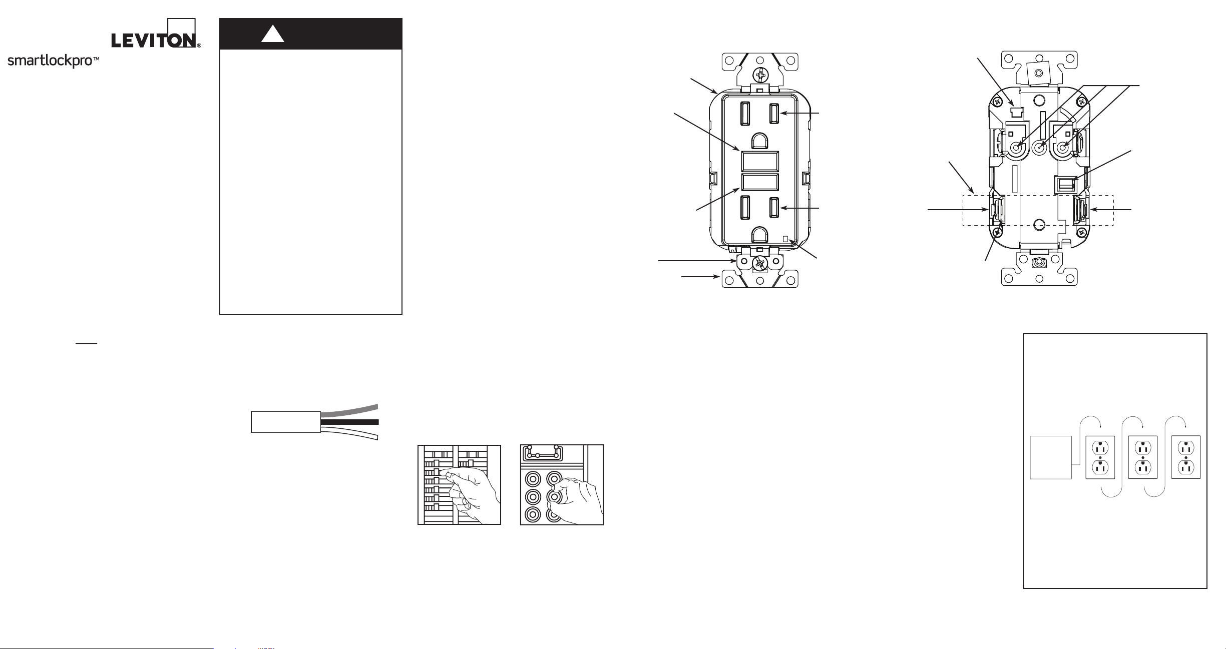
2. The LEV-LOKTM Modular GFCI's features
FRONT VIEW
Receptacle
RESET
button:
See step 8
TEST button:
See step 8
Self-Ground
Clip
Mounting
Bracket
FOLLOW INSTRUCTIONS
SUIVEZ INSTRUCTIONS
RESET
RESET
TEST
TEST MENSUEL
TEST MONTHLY
TEST
Outlet
Outlet
LED
Indicator
Light
Receptacle Tab #1
A yellow sticker covers
the LOAD terminals. DO
NOT remove the sticker
at this time.
(Remove only if load
terminals will be used
and then break off tab
with pliers)
LOAD
Hot terminal
(Brass or Black):
Connection for
the LOAD cable's
black wire
Back wire
BACK VIEW
HOT WIRE
FIL ACTIF
FIL BLANC
WHITE WIRE
Receptacle
Pin
Contacts
Receptacle
Tab #2
LOAD
White terminal
(Silver):
Connection for
the LOAD cable's
white wire
3. Should you install it?
Installing a GFCI receptacle can be more
complicated than installing a conventional
receptacle.
Make sure that you:
• Understand basic wiring principles and
techniques
• Can interpret wiring diagrams
• Have circuit wiring experience
•
Are prepared to take a few minutes to
test your work, making sure that you
have wired the GFCI receptacle correctly
4. LINE cable
A cable consists of 2 or 3 wires.
Cable Wires
LINE cable:
Delivers power from the service panel
(breaker panel or fuse box) to the GFCI. If
there is only one cable entering the electrical
box, it is the LINE cable. This cable should be
connected to Cat. No. MSTWL module cables
only.
LOAD cable:
Delivers power from the GFCI to another
receptacle in the circuit. This cable should be
connected to the GFCI's LOAD terminals only.
The LOAD terminals are under the yellow
sticker. Do NOT remove the sticker at this
time.
5. Turn the power OFF
Plug an electrical device, such as a lamp or
radio, into the receptacle on which you are
working. Turn the lamp or radio ON. Then,
go to the service panel. Find the breaker or
fuse that protects that receptacle. Place the
breaker in the OFF position or completely
remove the fuse. The lamp or radio must
turn OFF.
Next, plug in and turn ON the lamp or radio at
the receptacle's other outlet to make sure the
power is OFF at both outlets. If the power is
not OFF, stop work and call an electrician to
complete the installation.
6. Identify cables/wires
Important:
DO NOT install the GFCI receptacle in an
electrical box containing (a) more than four (4)
wires (not including the grounding wires) or
(b) cables with more than two (2) wires (not
including the grounding wire). Contact a
qualified electrician if either (a) or (b) are true.
If you are replacing an old receptacle, pull it
out of the electrical box without disconnecting
the wires.
•
If you see one cable (2-3 wires), it is the
LINE cable. The receptacle is probably in
position C (see diagram to the right).
Remove the receptacle and go to step 7A.
• If you see two cables (4-6 wires), the
receptacle is probably in position A or B
(see diagram to the right). Follow steps
a-e of the procedure to the right.
Procedure: box with two (2) cables (4-6
wires):
(a) Detach one cable's white wire and hot
wires from the receptacle and cap each
one separately with a wire connector.
Make sure that they are from the same
cable.
(b) Re-install the receptacle in the electrical
box, attach faceplate, then turn the
power ON at the service panel.
(c) Determine if power is flowing to the
receptacle. If so, the capped wires are
the LOAD wires. If not, the capped wires
are the LINE wires.
(d) Turn the power OFF at the service panel,
label the LINE and LOAD wires, then
remove the receptacle.
(e) Go to step 7B.
Placement in circuit:
The GFCI's place in the circuit
determines if it protects other receptacles
in the circuit.
Sample circuit:
Placing the GFCI in position A will also
provide protection to "load side"
receptacles B and C. On the other hand,
placing the GFCI in position C will not
provide protection to receptacles A or B.
Remember that receptacles A, B, and C
can be in different rooms.
Page 2
WHITE WIRE
FIL BLANC
HOT WIRE
FIL ACTIF
LOCK
UNLOCK
Black
Black
Green
White
White
White
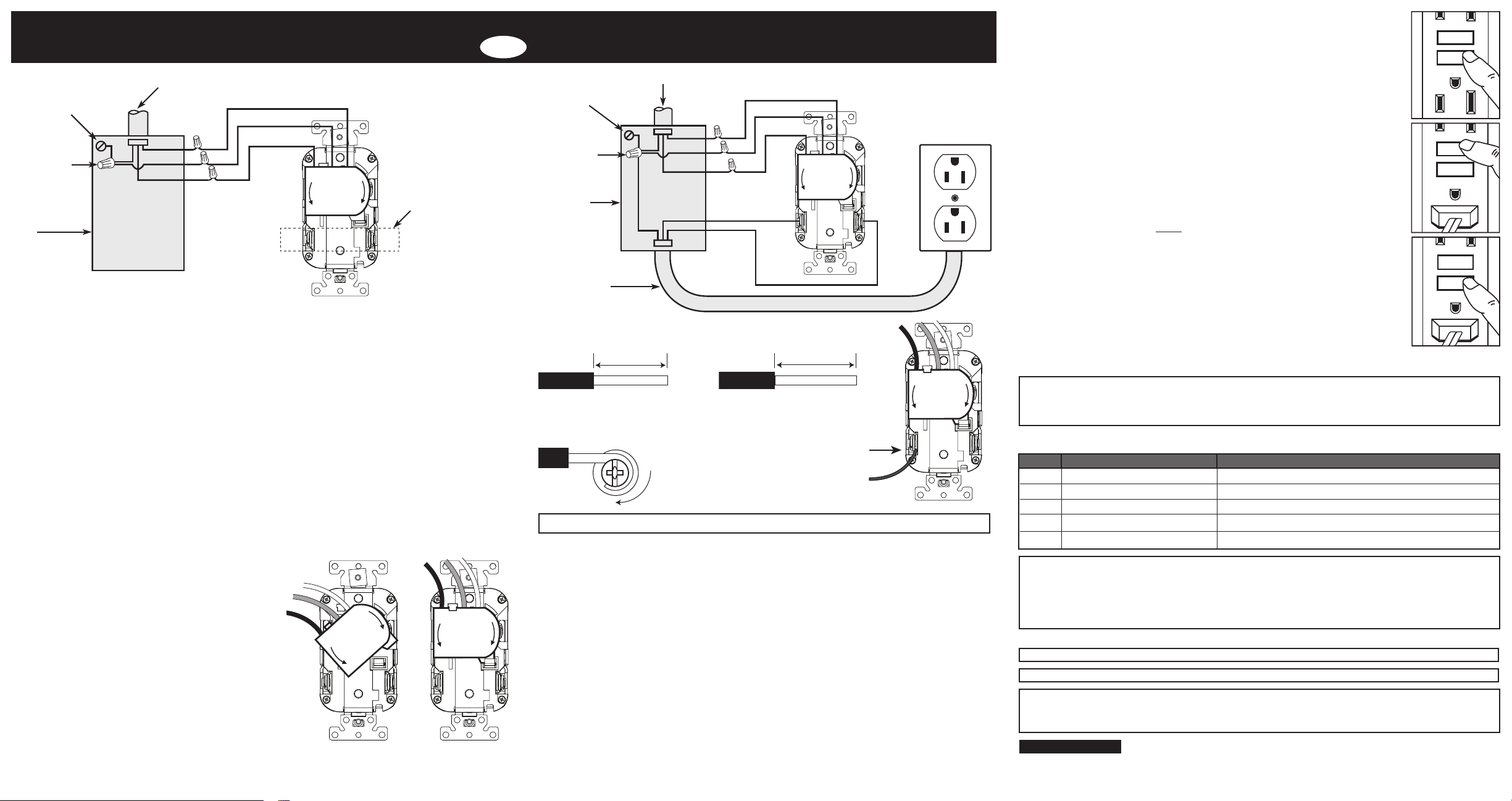
7. Connect the wires (choose A or B)... only after reading other side completely
RESET
TEST
TEST
RESET
RESET
TEST
TEST
RESET
RESET
TEST
TEST
RESET
Wire
19/32" (1.5 cm)
Wire
3/4" (1.9 cm)
A: One Cable (2 or 3 wires) entering the box O B: Two cables (4 or 6 wires) entering the box
Grounding connection
to box (if box has a
grounding terminal)
Wire
Connector
Electrical
Box
Connect Lev-Lok Module:
•
Remove pre-cut insulation from module leads, twist all strands tightly together, and strip wall
box wires [about 5/8" (1.6 cm)].
Connect the LINE cable wires to the LINE leads of the Lev-Lok module:
• The white wire connects to the WHITE lead of the Lev-Lok module.
• The black wire connects to the BLACK lead of the Lev-Lok module.
Connect the grounding wire (only if there is a grounding wire):
• For a box with no grounding terminal (diagram not shown): Connect the LINE cable's bare
copper (or GREEN) wire directly to the GREEN lead of the Lev-Lok module.
• For a box with a grounding terminal (diagram shown above): Connect a 6-inch bare copper (or
GREEN) 12 or 14 AWG wire to the GREEN lead of the Lev-Lok module. Also connect a similar
wire to the grounding terminal on the box. Connect the ends of these wires to the LINE cable's
bare copper (or GREEN) wire using a wire connector. If these wires are already in place, check
the connections. NOTE: Push wires firmly into wire connectors. Screw connectors on clockwise
making sure that no bare wire shows below the connector and secure each connector with
electrical tape.
Connect Lev-Lok Module to GFCI:
• Remove protective label from module to expose
contacts. Align rounded end of module with
rounded guide on back of GFCI and push
module contacts onto GFCI pin contacts (Fig. A).
Turn module clockwise until it locks under GFCI
tabs with an audible "snap" (Fig. B). Module
must be seated flush with GFCI base when
properly installed.
WARNING: Module can only be inserted one
way onto GFCI. Do not attempt to force improper
orientation as damage to module or GFCI may
occur. DO NOT USE GFCI OR MODULE IF
TABS ARE BROKEN!
Complete the installation:
• Fold the wires into the box, keeping the
grounding wire away from the WHITE and HOT
leads. Screw the GFCI to the box and attach the
faceplate.
• Go to step 8.
LINE cable brings
power to the GFCI
Green
Black
Yellow sticker
LOCK
remains in place
to cover the
UNLOCK
HOT WIRE
FIL ACTIF
WHITE WIRE
FIL BLANC
LOAD terminals
(Remove only if
load terminals
will be used and
then break off
tab with pliers go to 7B)
Fig. A Fig. B
LOCK
UNLOCK
HOT WIRE
FIL ACTIF
FIL BLANC
WHITE WIRE
UNLOCK
HOT WIRE
FIL ACTIF
OR
Grounding connection
to box (if box has a
grounding terminal)
Wire
Connector
Electrical
Box
LOAD cable
feeds power
to other
receptacle(s)
About Wire Connections:
Side Wire:
For Side wire -
Loop clockwise 2/3 of
the way around screw
NOTE: LOAD wiring terminals accept #10 - #14 AWG solid or stranded copper wire.
Connect the LINE cable wires to the LINE leads of the Lev-Lok module:
• The white wire connects to the WHITE lead of the Lev-Lok module.
• The black wire connects to the BLACK lead of the Lev-Lok module.
Connect the LOAD cable wires to the LOAD terminals:
• Remove the YELLOW sticker to reveal the LOAD terminals.
LOCK
WHITE WIRE
FIL BLANC
• The white wire connects to the WHITE terminal (Silver).
• The black wire connects to the HOT terminal (Brass or Black).
Connect the grounding wires (only if there is a grounding wire):
• Connect a 6-inch bare copper (or GREEN) 12 or 14 AWG wire to the GREEN lead of
the Lev-Lok module.
the grounding terminal on the box. Connect the ends of these wires to the LINE or LOAD
cable's bare copper (or GREEN) wire using a wire connector. If these wires are already
in place, check the connections.
connectors on clockwise making sure that no bare wire shows below the connector and
secure each connector with electrical tape.
Complete the installation:
• Fold the wires into the box, keeping the grounding wire away from the WHITE and HOT
terminals. Screw the receptacle to the box and attach the faceplate.
• Go to step 8.
LINE cable brings power to the GFCI
Back Wire:
For Back wire -
Insert bare wire
fully and tighten
terminal clamp on
conductor ONLY
If the box has a grounding terminal, also connect a similar wire to
NOTE: Push wires firmly into wire connectors. Screw
UNLOCK
HOT WIRE
FIL ACTIF
LOCK
WHITE WIRE
FIL BLANC
8. Test your work
Why perform this test?
• If you miswired the GFCI it may not prevent personal injury or death due
to a ground fault (electrical shock).
• If you mistakenly connect the LINE wires to the LOAD terminals, the GFCI
will not reset and will not provide power to either the GFCI
receptacle face or any receptacles fed from the GFCI.
Procedure:
(a)
This GFCI is shipped from the factory in the tripped condition and cannot
be reset until it is wired correctly and power is supplied to the device.
Plug a lamp or radio into the GFCI (and leave it plugged in). Turn the
power ON at the service panel. Ensure that the GFCI is still in the tripped
condition by pressing the TEST button. If the indicator light on the GFCI
receptacle face is ON and the lamp or radio is OFF go to the
Troubleshooting section because LINE and LOAD wiring connections have
been reversed. You will not be able to RESET the GFCI in this condition.
(b) Press the RESET button fully. If the lamp or radio turns ON and the
Indicator Light turns ON, the GFCI has been installed correctly. If the GFCI
cannot be reset, go to the Troubleshooting section.
(c) If you installed your GFCI using step 7B press the TEST button, then plug
a lamp or radio into surrounding receptacles to see which one(s), in
addition to the GFCI, lost power when you pressed the TEST button. DO
NOT plug life saving devices into any of the receptacles that lost power.
Place a "GFCI PROTECTED OUTLET" sticker on every receptacle that
lost power, then press the RESET button to reset the GFCI.
(d) Press the TEST button (then RESET button) every month to assure proper
operation. If the Indicator light does not go out and come back on or if the
GFCI cannot be reset, then it must be replaced.
Turn the power OFF and check the wire connections against the appropriate wiring diagram in
step 7A or 7B. Make sure that there are no loose wires or loose connections. Start the test from
the beginning of step 8 if you rewired any connections to the GFCI.
Ratings DescriptionCat. No.
15A-125V ACMN759
20A-125V ACMN789
15A-125V ACMX759
MX789
Leviton warrants to the original consumer purchaser and not for the benefit of anyone else that this product at the time of its sale by Leviton is free of defects in
materials and workmanship under normal and proper use for two years from the purchase date. Leviton’s only obligation is to correct such defects by repair or
replacement, at its option. For details visit www.leviton.com or call 1-800-824-3005. This warranty excludes and there is disclaimed liability for labor for removal
of this product or reinstallation. This warranty is void if this product is installed improperly or in an improper environment, overloaded, misused, opened, abused, or
altered in any manner, or is not used under normal operating conditions or not in accordance with any labels or instructions. There are no other or implied warranties
of any kind, including merchantability and fitness for a particular purpose, but if any implied warranty is required by the applicable jurisdiction, the duration
of any such implied warranty, including merchantability and fitness for a particular purpose, is limited to two years. Leviton is not liable for incidental, indirect,
special, or consequential damages, including without limitation, damage to, or loss of use of, any equipment, lost sales or profits or delay or failure to
perform this warranty obligation. The remedies provided herein are the exclusive remedies under this warranty, whether based on contract, tort or otherwise.
SmartlockPro is a Trademark of Leviton Manufacturing Co., Inc. registered in the United States, Canada, Mexico and China.
Lev-Lok is a Trademark of Leviton Manufacturing Co., Inc. in the United States, Canada and Mexico.
This product is covered by U.S. Patent Nos. 6,040,967; 6,246,558; 6,282,070; 6,381,112; 6,437,953; 6,646,838;
6,657,834; 6,788,173; 6,864,766; 6,900,972; 6,944,001; 7,082,021; 7,336,458; 7,355,117; 7,400,479; 7,463,124;
7,697,252; 7,737,809; 7,764,151; 7,820,909*; 7,868,719*; 7,907,371; 8,054,595; 8,130,480; 8,242,362*
and corresponding foreign patents (*applies only to MX759 and MX789).
FOR CANADA ONLY
For warranty information and/or product returns, residents of Canada should contact Leviton in writing at Leviton
Manufacturing of Canada Ltd to the attention of the Quality Assurance Department, 165 Hymus Blvd, Pointe-Claire
(Quebec), Canada H9R 1E9 or by telephone at 1 800 405-5320.
20A-125V AC
All devices rated 20A feed-through
For Technical Assistance Call: 1-800-824-3005 (U.S.A. Only) 1 800 405-5320 (Canada Only) www.leviton.com
TROUBLESHOOTING
General Information
LEV-LOKTM Slim Modular GFCI Duplex Receptacle
LEV-LOKTM Slim Modular GFCI Duplex Receptacle
LEV-LOKTM Slim Modular Tamper Resistant GFCI Duplex Receptacle
LEV-LOKTM Slim Modular Tamper Resistant GFCI Duplex Receptacle
LIMITED 2 YEAR WARRANTY AND EXCLUSIONS
PK-93844-10-00-2A
 Loading...