

Page 1
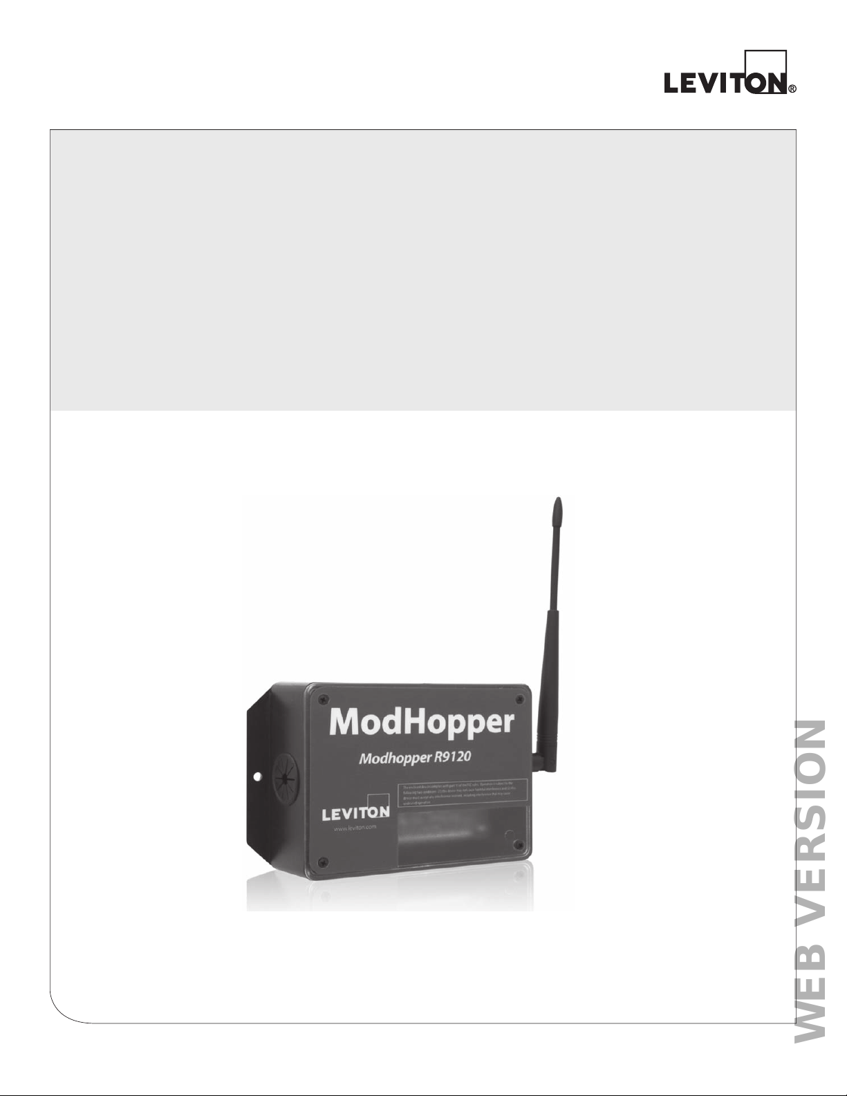
ModHopper® - Wireless Modbus/Pulse Transceiver
WEB VERSION
Cat. No. R9120
Installation and Operation Manual
DI-007-R9120-00A
Page 2

WEB VERSION
Page 3

TABLE OF CONTENTS
WEB VERSION
1 Product Application Limitation ............................................................................4
2 Features and Specifications ................................................................................5
3 Overview and Installation Checklist ....................................................................6
3.1 Overview ............................................................................................................6
3.2 Installation Checklist ..........................................................................................6
3.3 Model Information ..............................................................................................6
4 Hardware Installation ............................................................................................7
5 Configuration .........................................................................................................8
6 Modbus Registers ...............................................................................................13
6.1 Supported Modbus Functions ..........................................................................13
6.2 Modbus Register List .......................................................................................13
7 Mechanical Drawings ..........................................................................................16
8 Warranty and Contact Information......................................................................17
Page 4
1 PRODUCT APPLICATION LIMITATION
WEB VERSION
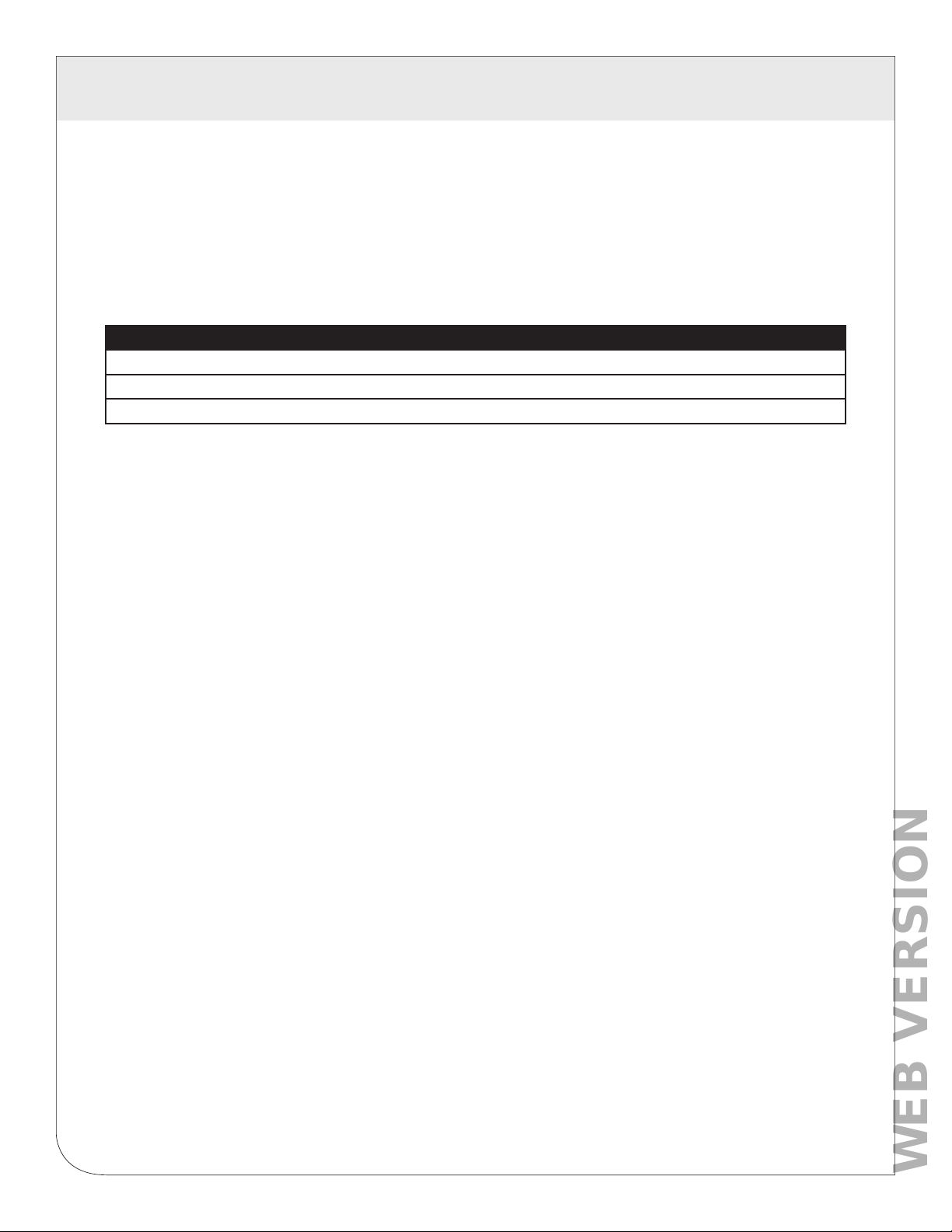
• Leviton products are not intended for use in critical applications such as nuclear facilities, human
implantable devices or life support. Leviton is not liable, in whole or in part, for any claims or damages
arising from such uses.
• Leviton strongly believes in continuous improvement, therefore we must reserve the right to change
specifications and product offerings without notice. Where possible, we will substitute products with
equivalent functionality when necessary.
NOTICE
This product is not intended for life safety applications.
Do not install this product in hazardous or classified locations.
The installer is responsible for conformance to all applicable codes.
4
Page 5
2 FEATURES AND SPECIFICATIONS
WEB VERSION
The ModHopper wireless Modbus/pulse transceiver is designed to allow systems integrators the ability to communicate
with remote locations while avoiding the costs associated with running low voltage wiring to multiple locations in a single
or between multiple buildings. To meet these requirements, the ModHopper
TM
provides the installer with all the tools
necessary to install and configure the hardware and software with a minimum of time and investment.
Applications
The R9120 wireless Modbus/pulse transceiver has several applications. These include:
• Energy monitoring.
• Solar PV power generation monitoring.
• Malls, office buildings, and other tenant energy monitoring applications.
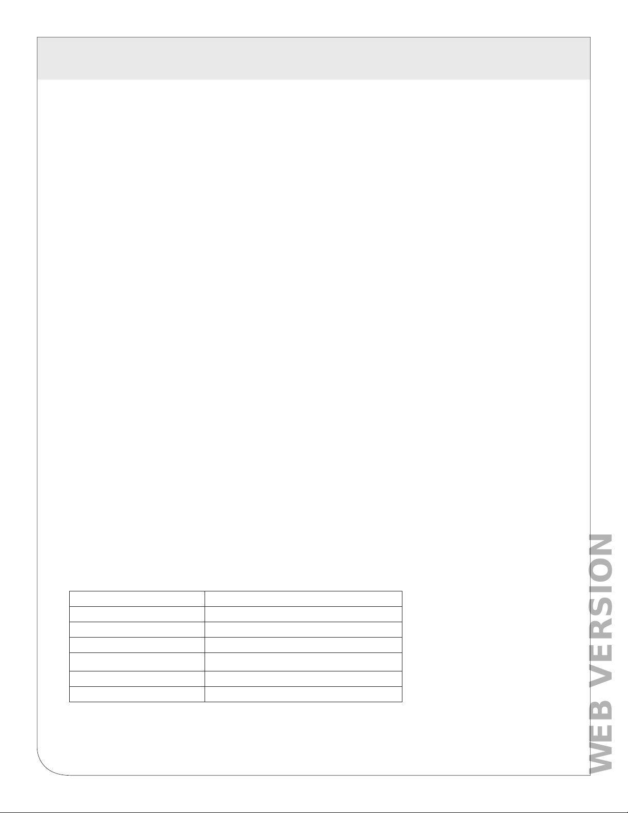
Processor 60MHz Arm7 embedded CPU
LED 3 x RF, 2 x RS485, 2 x pulse, Alive, Alarm
Protocols Modbus RTU
Addressing Modbus address may be set from 1 to 247 via DIP switch. Included Class 2
Power Supply
(power supply not included in models with -T option)
2
Inputs
Monitor consumption/rate/min/max
Pulse rate/width user selectable to 10Hz, 50Hz, 100Hz, or 250Hz.
Pulse rate option: 10Hz, minimum pulse width 50ms
Pulse rate option: 50Hz, minimum pulse width 10ms
Pulse rate option: 100Hz, minimum pulse width 5ms
Pulse rate option: 250Hz, minimum pulse width 2ms
Contact closure threshold 100Ω to 2.5kΩ user selectable
Pulse count values are stored in non-volatile memory
Communications
Supports up to 32 external devices per ModHopper. (expandable)
RF Frequency hopping, ISM band, see table below.
North America: Temperature 0
Environmental
For indoor and outdoor use when used in an appropriate enclosure.
The R9120 must be mounted inside a NEMA rated electrical enclosure for safety and isolation
EMC FCC (USA): Part 15.247, Class A
IC (Canada): RSS-210
Size 6.5” x 4.5” x 2.0” (260mm x 64mm x 45mm)
Mass 1.25 lbs (0.67 kg)
1,3
Power supply requires 100-240VAC, 50/60Hz 0.5A
2 pulse inputs, dry contact
1
RS485 (+,-, S), 9600/19200 baud, N, 8, 1, two wire.
2
Pollution Degree 2, altitude up to 2000M.
requirements when used outdoors.
o
– 50o c3, 0 – 95% humidity, non-condensing.
Product specific features: R9120-5 (extended range)
FCC ID OUR-9XTEND or MCQ-XBPSX
IC (Industry Canada) 4214A-9XTEND or 1846A-XBPSX
Encryption 256 bit AES
Max Range (indoor/urban) 3000ft
RF: 900MHz, 1000mW
Power Input
1
Inputs are intended for low voltage Class 2 or inputs or outputs.
2
if the product is used in a manner not specified by the manufacture, the protection provided by the equipment may be
impaired.
3
Not intended for use with rechargeable batteries
3
9-30VDC, 900mA
5
Page 6

3 OVERVIEW AND INSTALLATION CHECKLIST
WEB VERSION
3.1 Installation Checklist
A ModHopper system installation has the following components:
Required hardware
• Two or more ModHopper R9120 transceivers.
External Hardware
RS485 Modbus master system such as an A8812 EMH™ or a Modbus compatible PLC.
•
• Optional: RS485/Modbus slave devices such as power meters or IO modules.
• Optional: Pulse output transducers for measuring gas, electricity, water, etc. from existing meters and
sensors. Make sure to obtain the pulse output scale, or multiplier for each device you will
be using.
• Low voltage wire for attaching pulse or Modbus devices to the R9120, typically 18-24 gauge
3.2 Model Information
Before proceeding with the installation, verify the hardware is Rev C. It is important to use
the correct manual that matches the hardware being installed.
As per SIPCO LLC, this product may be used in a system and employ or practice certain
features and/or methods of one or more of the following patents:
SIPCO, LLC
This product is covered by U.S. Patent No’s: Patent No. 7,103,511, Patent No. 6,914,893,
Patent No. 6,891,838, Patent No. 5,714,931, Patent No. 6,233,327, Patent No. 7,397,907, Patent No. 6,618,578,
Patent No. 7,079,810, Patent No. 7,295,128, Patent No. 7,263,073, Patent No. 7,480,501, Patent No. 6,437,692,
Patent No. 7,468,661, Patent No. 7,053,767, Patent No. 7,650,425, Patent No. 7,739,378
6
Page 7
4 HARDWARE INSTALLATION
WEB VERSION
4.1 Hardware Installation
WARNING: TO AVOID DEATH OR INJURY, after wiring the ModHopper, remove all scraps of wire or foil
shield from the electrical panel. This could be dangerous if wire scraps come into contact with high
voltage wires.
4.1.1 Unpack materials; Remove all materials from shipping box and verify all required components
are present.
4.1.2 Mount the ModHopper to a wall or inside the electrical enclosure if required. When mounting the ModHopper
and the antenna inside an enclosure, a non-metallic enclosure will be required. Metal enclosures restrict RF
communications. If a metal enclosure is required, use an external antenna and an RF antenna cable.
4.1.3 Connect the pulse output devices. For KYZ pulse output meters, attach the normally-open circuit to the
ModHopper. These are usually the K and Z terminals.
4.1.4 Connect the RS485 Modbus network loop as shown in the wiring diagram. Follow the manufacturer’s
instructions for installing and powering other Modbus devices. Verify that the Modbus address settings are
unique for each device (i.e., no two devices with the same address). Connect each device in the chain by
“daisy-chaining” the devices together. Observe + and - polarity on the Modbus devices. For more information
about Modbus loops, please read our Modbus FAQ available at www.Leviton.com.
Do not ground the RS485 shield inside an electrical panel. All RS485 and 24VDC power wires,
including the shield should be insulated to prevent accidental contact to high voltage conductors.
The pulse, RS485 and power cable should be mechanically secured where it enters
the electrical panel.
The wire used to provide pulse and RS485 communications should be insulated to meet the requirements of
the voltages present whatever box in which the wire is mounted. For example, BeldenTM 1120A has a 600V
insulation rating and can be used in many applications. Check with your electrical installer for details as local
code requirements may vary.
4.1.5 Attach the antenna to the ModHopper. When using an antenna cable, avoid sharp bends; kinks in the
antenna cable will degrade performance.
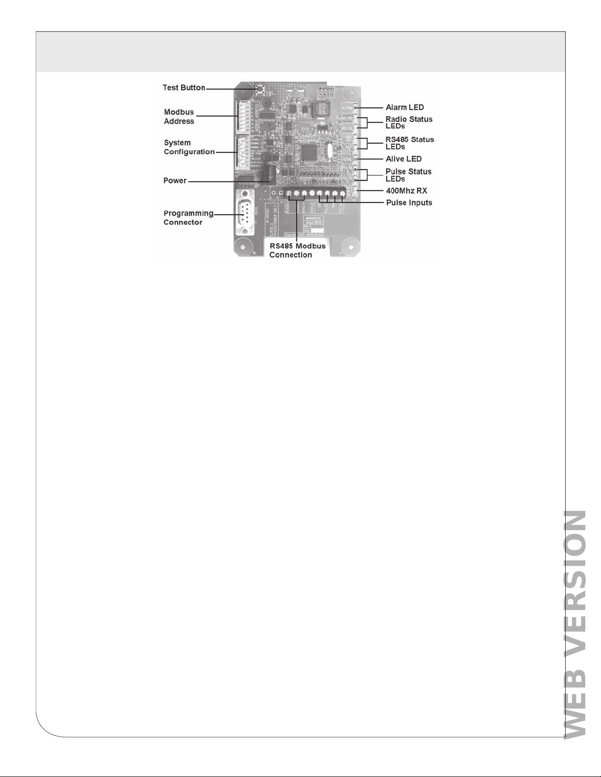
4.1.6 Attach the power to the ModHopper and apply power. Observe the LEDs to confirm the device is operating.
• Alive (green): blinks once per second while the system is operating correctly.
• RS485 RX: The RX led should blink whenever a modbus query is sent on the RS485 loop. (regardless of
the target address of the query). If the ModHopper is attached to an EMH, the RX led should blink about
once per second.
• RS485 TX: The TX LED will blink when the R9120 responds to a modbus query.
Note: If cleaning is required, use a dry towel to remove dust from the ModHopper.
CAUTION: Do not use fluids to clean the ModHopper.
7
Page 8
5 CONFIGURATION
WEB VERSION
5.1 Modbus Address
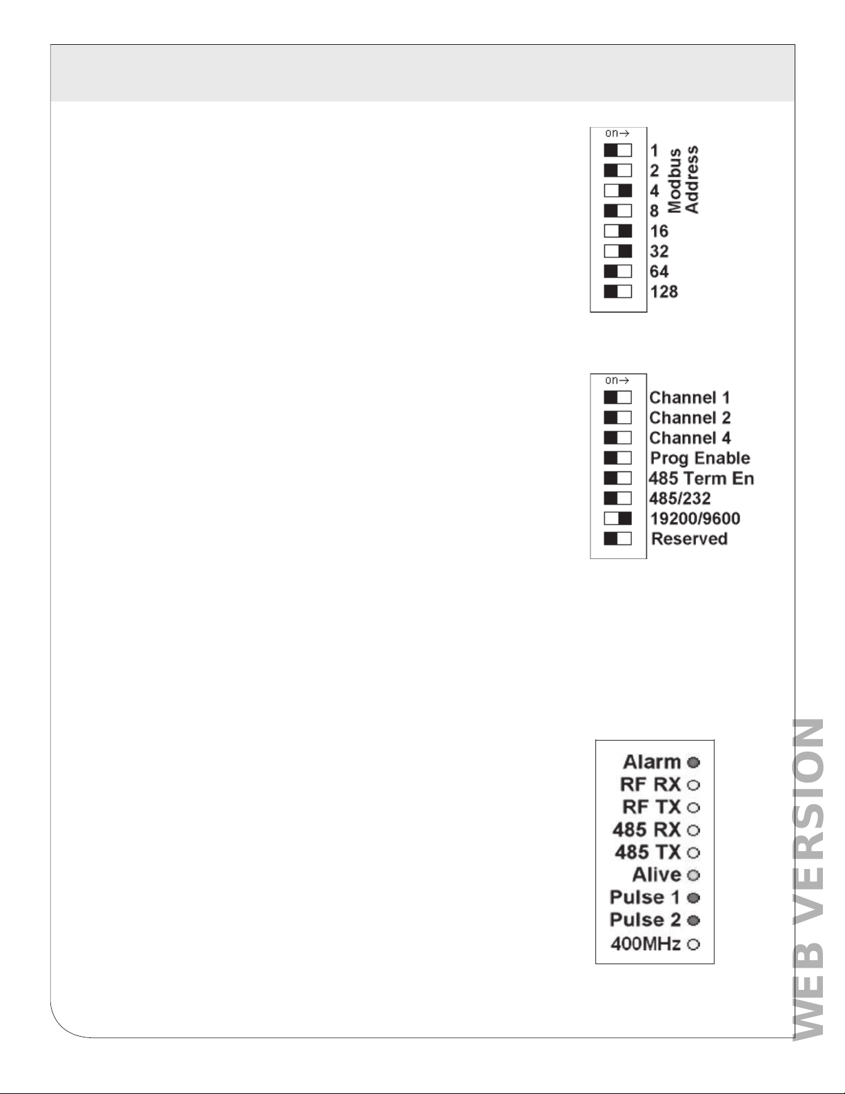
Before the ModHopper can be used, you must set the Modbus address of
the ModHopper. This address must be unique among all Modbus devices in
the system including all devices that are connected on remote wireless links.
Address 0 (all switches off) is not allowed.
Select an address, and set the DIP switches to match.
The sum of the value of the switches is the address. In the example to the
right, address 52 is set by placing switch 4, 16 and 32 to the on position.
Note: 4 + 16 + 32 = 52
5.2 System Setting
For most systems, set all of the system switches to the “off” position.
Radio channel: This option selects the channel number that can be used to
isolate a group of ModHoppers. This option may be set for channels 0 to 6.
Channel 7 (all 3 switches on) is not allowed.
Programming: Set the “Prog Enable” to Off for normal operation.
485 Termination Enable: Set the “485 Term En” to ON to enable a 120 ohm
termination resistor on the RS485 network. This should be used when the
ModHopper is on the end of a 485 wiring run. Set this switch to OFF when the
ModHopper is in the middle of an RS485 wiring run.
Port RS232 or RS485: Set the switch to the “off” position for RS485 operation.
The ModHopper can communicate via the RS232 connection however most
Modbus devices will need 485 terminals.
Baud Rate: This option sets the serial port speed for the Modbus devices connected to the ModHopper.
Set this option to “off” for 19200. Set the switch to “on” for 9600 baud.
Reserved: Set this option to Off.
5.3 Status LEDs
The device should power up and be ready in a few seconds. The LEDs should
blink in the following manner.
• The “Alive” LED should start to blink about once per second.
• The Alarm LED will blink when transmission errors occur.
• The RF TX/RX LEDs will blink when the radio is receiving
or transmitting data.
• The RS485 LEDs will blink for local Modbus activity.
• The Pulse input LEDs will light when the corresponding pulse input
terminals are closed.
• If the device has the -SN option, the 400MHz LED will blink when an RF
packet from a 400MHz sensor transmitter is received.
8
Page 9

5 CONFIGURATION
WEB VERSION
5.4 Signal Strength Test
When the ModHopper is operating, the Test Button can be used to report the signal strength received by the
ModHopper from another unit.
Press and hold down the test button. The status LEDs will light up as a bar graph display. Each LED is
approximately 10% of scale. For example if PULSE 1 and 2 are on, the received strength is approximately
20% to 29%.
For useful signal reporting, it is important to turn off all but one other ModHopper. When reporting the signal
strength, the most recent wireless transmission received is displayed. If two ModHoppers are transmitting,
the display will only show the most recently received packet, and the user will not be able to determine which
ModHopper the signal strength being reported.
Note: the normal operation of the ModHopper is suspended while the test button is pressed.
Modbus communications and wireless transmissions are not processed.
5.5 Monitoring usage
The ModHopper has several data points that may be read using the Modbus protocol.
For each of the two pulse inputs, the ModHopper reports a value for consumption and rate. Rate fields are
provided for the average rate during the log period (block demand), the instantaneous rate, and the min/max
instantaneous rate observed during the log period. The pulse counts for each input are stored in
non-volatile memory to preserve the count when power is removed. For more information on the specific
Modbus registers used for the pulse inputs, refer to the Modbus register section of this manual.
When configuring a Modbus Master such as a PLC, TCP Gateway, or computer software, you must increase
the timeout on the RS485 port of your system. The ModHopper adds about 500mS of delay per hop. In a
complex system with multiple ModHoppers, a 1 to 2 second round trip time is not uncommon.
9
Page 10
5 CONFIGURATION
WEB VERSION
5.6 EMH Data Display Page
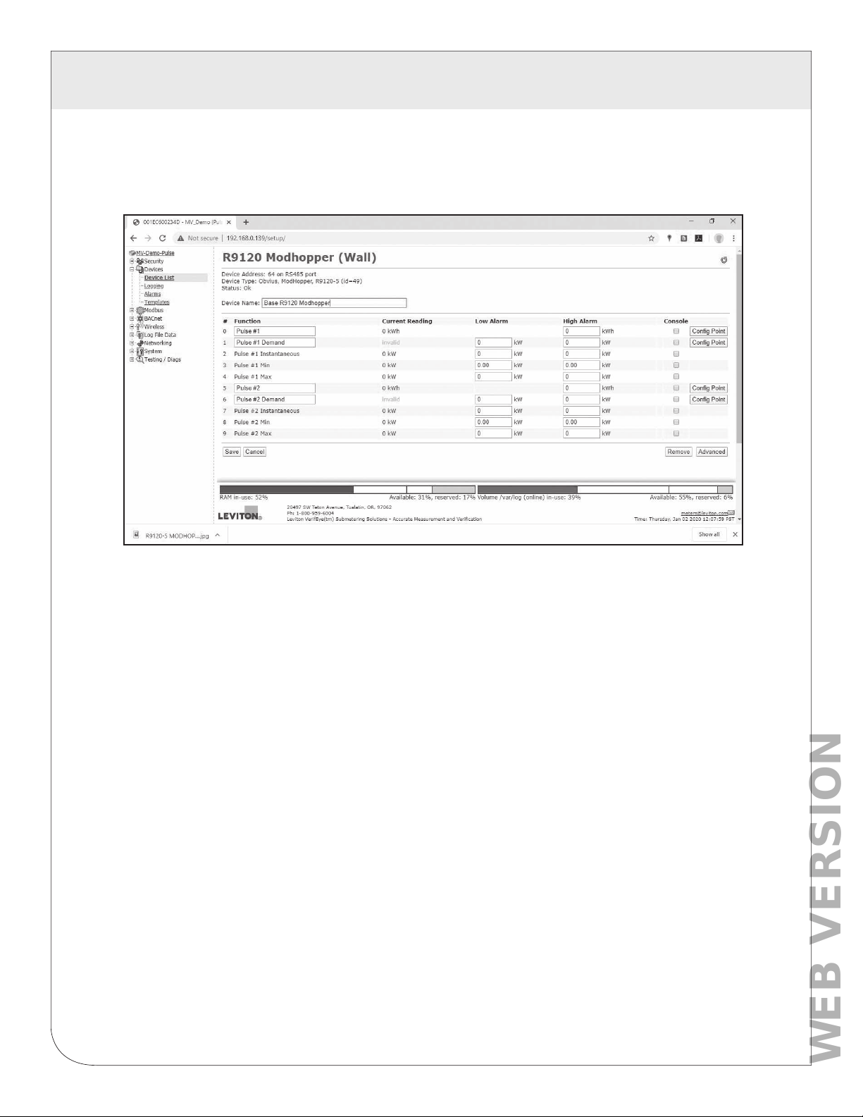
When using the ModHopper with the EMH data acquisition server, the EMH will read the pulse input data from
the ModHopper and provide configuration menus for all of the ModHopper options.
The EMH will display will report all the data values present on the ModHopper. In addition, the instantaneous
min/max rate values will be cleared after each logging interval. Click the Configure button to set up pulse input
names, unit of measure and multipliers as needed.
10
Page 11
5 CONFIGURATION
WEB VERSION
5.7 EMH Advanced Configuration Options
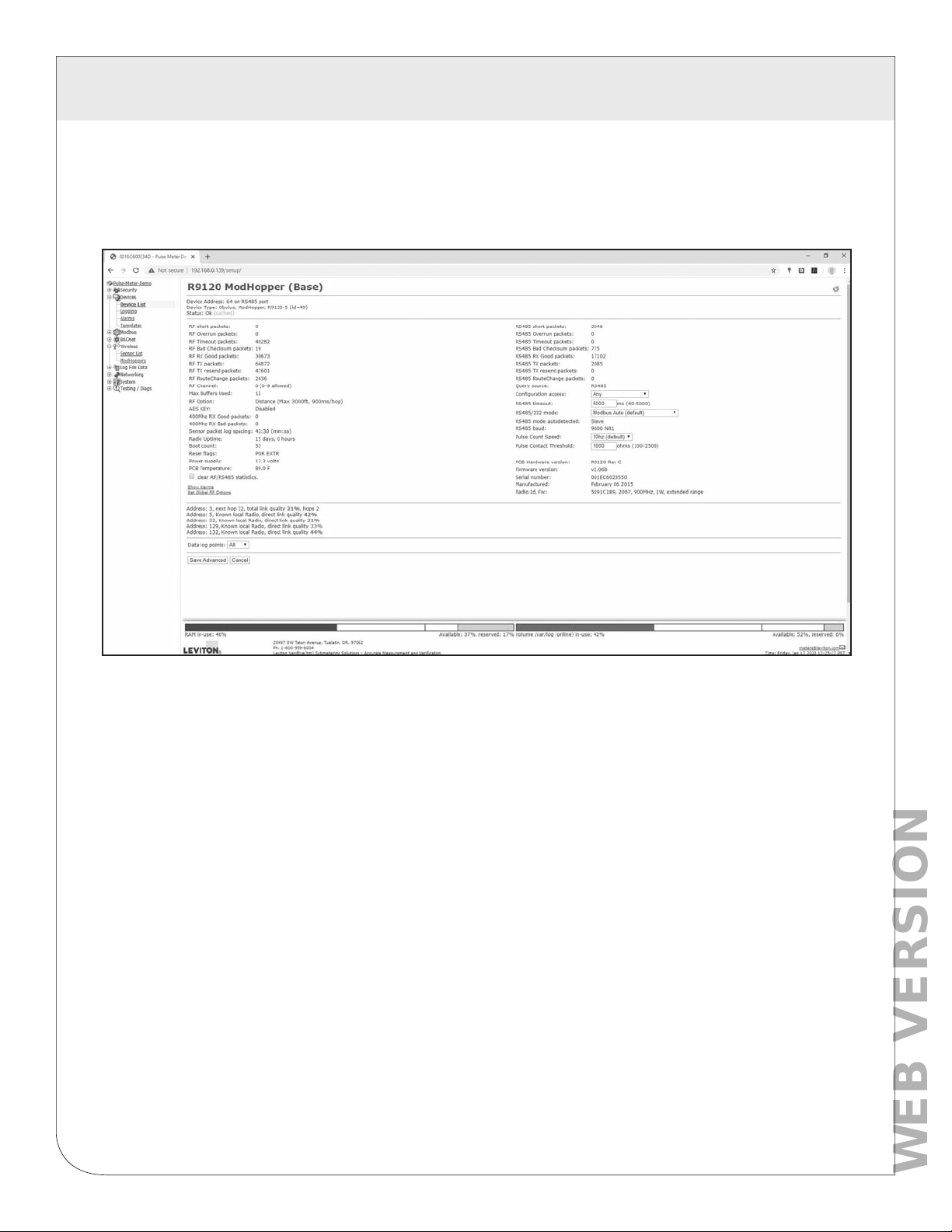
The EMH setup and configuration page includes an advanced configuration page to set all of the ModHopper
features with a convenient web page interface.
In this setup page, there are several options available.
• Serial port timeout, and protocol configuration. When a request comes in over the wireless mesh network and is sent
out on the ModHopper RS485 serial port, the ModHopper must wait for the attached Modbus device to reply to the
query. The timeout option controls how long the ModHopper will wait before giving up on the attached Modbus device
and discarding the query. Most Modbus devices will respond in 150ms or less.
• Pulse input contact closure threshold: allows you to set a maximum resistance to be counted as a “closed” contact.
This is helpful when using intrinsic barrier devices. Default of 500 ohms will work in most applications.
• Pulse input maximum count frequency. For most pulse meters, 10Hz is adequate. Faster counting of mechanical
relays may result in “relay bounce” and give an incorrect count. Consult the pulse output device for information on
maximum expected pulse output rate.
• Data log control: enable/disable EMH data logging for the ModHopper. Note: this is an internal EMH feature, and does
not set any registers on the ModHopper.
In addition to the configuration options, some further details about the ModHopper are provided. These
include the serial number, firmware version, uptime, RF/RS485 packet counters, and internal temperature and
power supply monitor. For further information configuration and status registers, refer to the Modbus
section in this manual.
11
Page 12
5 CONFIGURATION
WEB VERSION
5.8 EMH route mapping display
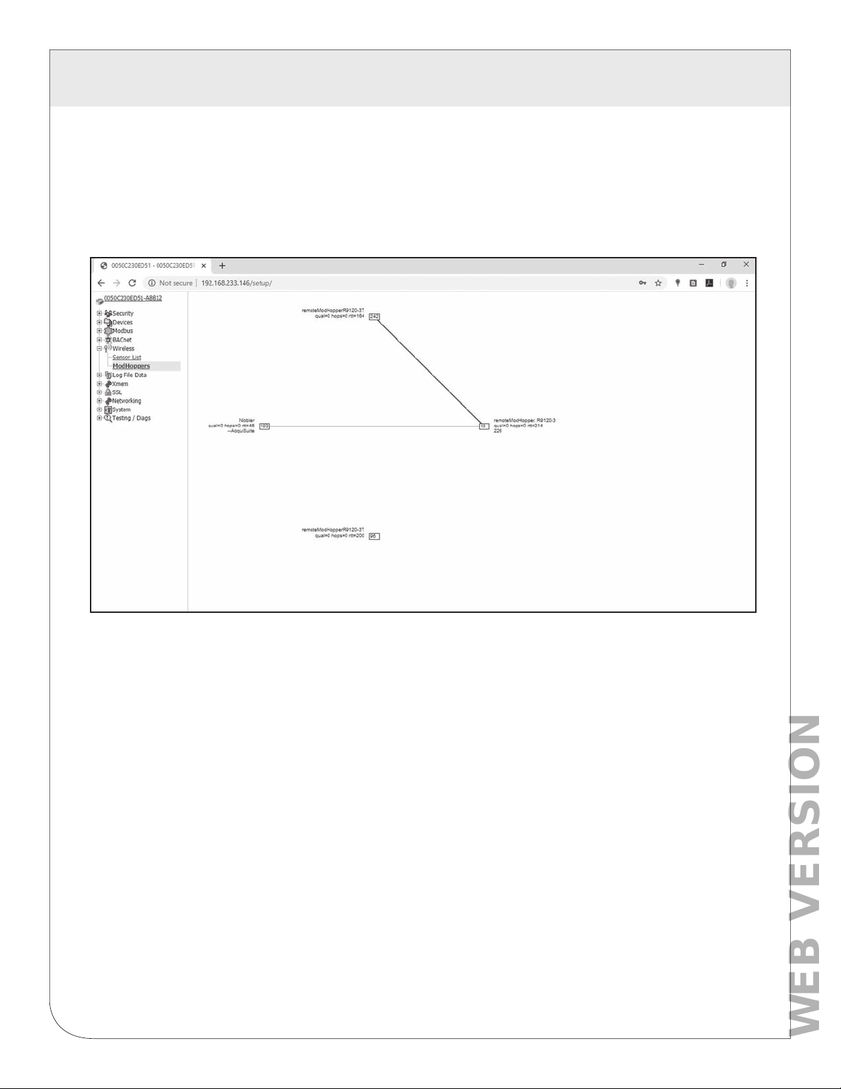
The EMH data acquisition server has additional diagnostic features that assist with ModHopper deployments.
The most useful is the ModHopper route map. Select the ModHoppers menu from the Wireless section in the
EMH menu tree as shown below.
The graph will draw a blue box for each ModHopper that is attached to the system. The blue number inside
the box icon is the Modbus address of the ModHopper. To the side of each icon, three lines of information will
be shown.
• The device list name will be shown to the side of each ModHopper icon
• The link quality, hops and round trip time (rtt) will be printed under the ModHopper name.
• A list of attached Modbus device addresses will be shown on the third line. This is a list of addresses
that the ModHopper has automatically detected on the local RS485 port.
The graph will print strong links in thick green lines. Lines progress from green to yellow to red to indicate
weak links.
12
Page 13
6 MODBUS REGISTERS
WEB VERSION
6.1 Supported Modbus Functions
The R9120 device responds to the following Modbus query functions:
0x11 Report slave ID.
0x03 read holding registers (multiple)
0x06 preset single register
These should be sufficient to perform all operations (read many values, make single change, and identify).
In addition the device will respond to with Modbus exceptions for invalid function, value, and register if out
of bound requests are made.
Modbus function 0x11 Slave ID function will respond with
ID=49 and one of the following ID text values: “Leviton, ModHopper, R9120-5”
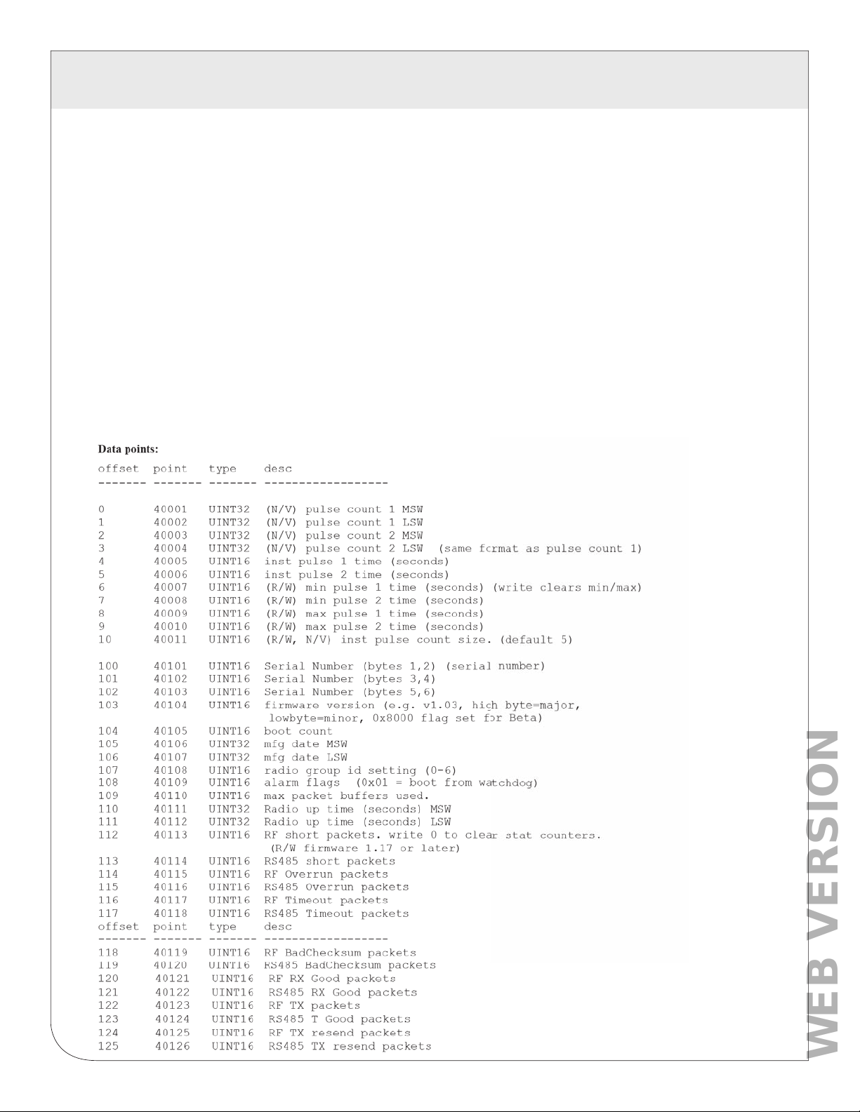
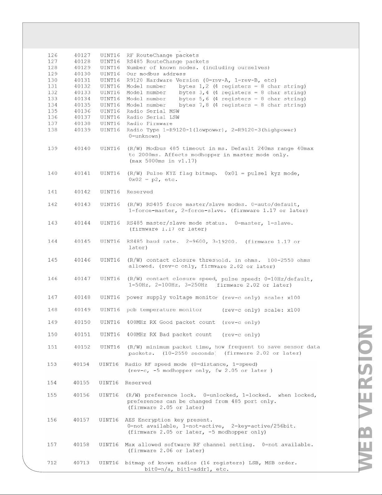
6.2 Modbus Register List
All modbus registers are read-only unless otherwise noted.
13
Page 14
6 MODBUS REGISTERS
WEB VERSION
14
Page 15

6 MODBUS REGISTERS
WEB VERSION
6.3 Register Functions
Pulse Count: The pulse count is stored as an unsigned 32bit integer. This allows for 2^32 pulses
(4.2 billion) to be counted before rollover. On Modbus systems that do not allow you to read 32 bit values,
you can calculate the pulse count as follows:
count = (MSW * 65536) + LSW
or
count = (MSW << 16) | LSW [bit shift high order word by 16 bits and x or against low order word ]
Pulse count registers accumulate a total number of pulses received on each pulse input. The pulse count
totals always increment and cannot be cleared or set to an arbitrary value to prevent tampering. All pulse
count totals are stored in non-volatile memory to preserve counts during power failure. The unsigned 32 bit
counter values can accumulate up to 4.29 billion (2^32) pulses before rollover.
All 32 bit data point values are encoded in 2 Modbus registers (16 bits each). Modbus master systems
should always query the A8332 using a single query to read an entire block of registers. Never use two
queries to read one register and then combine the two results into a single 32 bit value. Doing so will allow
the pulse count to increment in the middle of the two Modbus queries, and will cause intermittent data
readings that are incorrect.
For example, a pulse input has a count of 65534. This is represented as a 32 bit hex number 0x0000FFFE.
The first 4 digits are the MSW register, the second 4 digits are the LSW register. The Modbus Master reads
the first (MSW) register and gets 0x0000. In between the two readings, the pulse input counts 2 more
pulses, making the total 65536 or 0x00010000 in hex. Next the Master reads the second (LSW) register and
gets 0x0000. When the two registers are combined, the result is 0x00000000. The proper way to handle
this situation is to simply read both registers in a single Modbus query.
Instantaneous Pulse Rate: The pulse rate values for instantaneous, min and max rates are calculated
based on the time between arriving pulses. For example, if InstPulse1 = 30, and inst pulse count size is
5, then the average rate for the last 5 pulses is 6 seconds per pulse. To convert the register values (in
seconds) to a rate value, use the following formula.
RatePerHour = (N * 60 * 60 / Inst_Register)
Where InstRegister is any of the 6 register values 4 through 9. N is the instantaneous pulse count size at
offset 10.
Min/Max pulse rate: These 4 registers are calculated from the instantaneous pulse rate. These latching
registers are updated whenever the minimum or maximum rate fields are exceeded by the instantaneous
rate. These 4 registers may be cleared by writing a zero to the register. Writing to one min/max register
clears all four min/max registers.
15
Page 16
7 MECHANICAL DRAWINGS
WEB VERSION
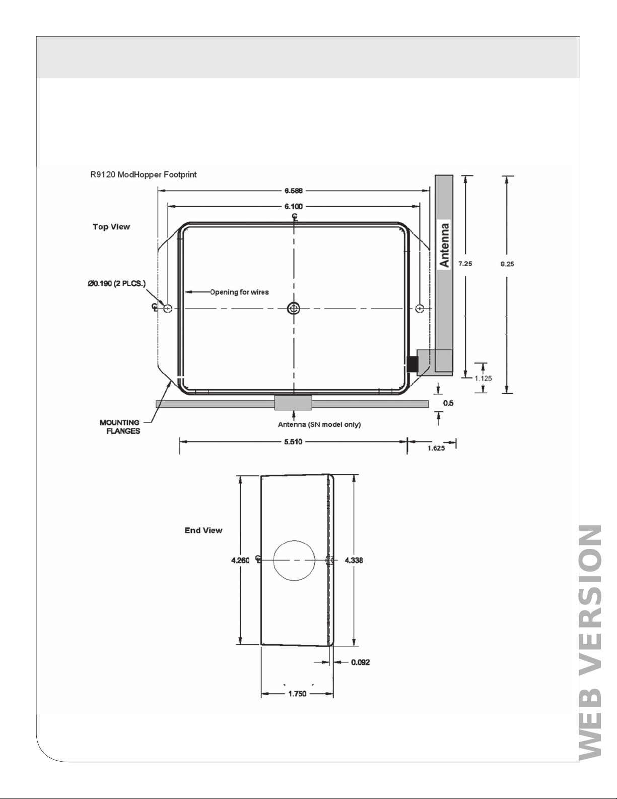
7.1 The R9120 must be wall mounted, or mounted inside an appropriate enclosure rated for the weather,
location, and electrical components located inside it. The R9120 mounting holes are detailed below.
16
Page 17

8 WARRANTY AND CONTACT INFORMATION
WEB VERSION
FCC STATEMENT:
This equipment has been tested and found to comply with the limits for a Class A digital device, pursuant to part 15 of the FCC
Rules. These limits are designed to provide reasonable protection against harmful interference when the equipment is operated
in a commercial environment. This equipment generates, uses, and can radiate radio frequency energy and, if not installed
and used in accordance with the instruction manual, may cause harmful interference to radio communications. Operation of
this equipment in a residential area is likely to cause harmful interference in which case the user will be required to correct the
interference at his own expense.
Any changes or modifications not expressly approved by Leviton Manufacturing Co., could void the user’s authority to operate
the equipment
TRADEMARK DISCLAIMER:
Use herein of third party trademarks, service marks, trade names, brand names and/or product names are for informational
purposes only, are/may be the trademarks of their respective owners; such use is not meant to imply affiliation, sponsorship,
or endorsement. Modbus is a U.S. registered trademark of Schneider Electric USA, Inc. The Leviton logo is a registered
trademark of Leviton Manufacturing Co., Inc. Modhopper is a registered trademark of Obvius, LLC.
FCC SUPPLIERS DECLARATION OF CONFORMITY:
Model R9120 manufactured by Obvius Holdings, LLC, 20497 SW Teton Avenue, Tualatin, OR 97062, www.obvius.com.
This device complies with part 15 of the FCC Rules. Operation is subject to the following two conditions: (1) This device may
not cause harmful interference, and (2) this device must accept any interference received, including interference that may
cause undesired operation.
IC STATEMENT:
This device complies with Industry Canada license-exempt RSS standard(s). Operation is subject to the following two
conditions: (1) this device may not cause interference, and (2) this device must accept any interference, including interference
that may cause undesired operation of the device.
Leviton Manufacturing Co., Inc.
201 North Service Road, Melville, NY 11747
Visit Leviton’s Web site at www.leviton.com
© 2020 Leviton Manufacturing Co., Inc. All rights reserved.
Specifications and price subject to change at any time without notice.
FOR CANADA ONLY
For warranty information and/or product returns, residents of Canada should contact Leviton in writing at Leviton
Manufacturing of Canada ULC to the attention of the Quality Assurance Department, 165 Hymus Blvd,
Pointe-Claire (Quebec), Canada H9R 1E9 or by telephone at 1 800 405-5320.
Leviton warrants to the original consumer purchaser and not for the benefit of anyone else that this product at the time of its sale by Leviton is free
of defects in materials and workmanship under normal and proper use for five years from the purchase date. Leviton’s only obligation is to correct
such defects by repair or replacement, at its option. For details visit www.leviton.com or call 1-800-824-3005. This warranty excludes and
there is disclaimed liability for labor for removal of this product or reinstallation. This warranty is void if this product is installed improperly or in an
improper environment, overloaded, misused, opened, abused, or altered in any manner, or is not used under normal operating conditions or not
in accordance with any labels or instructions. There are no other or implied warranties of any kind, including merchantability and fitness
for a particular purpose, but if any implied warranty is required by the applicable jurisdiction, the duration of any such implied warranty, including
merchantability and fitness for a particular purpose, is limited to two years. Leviton is not liable for incidental, indirect, special, or consequential
damages, including without limitation, damage to, or loss of use of, any equipment, lost sales or profits or delay or failure to perform this
warranty obligation. The remedies provided herein are the exclusive remedies under this warranty, whether based on contract, tort or otherwise.
LIMITED 5 YEAR WARRANTY AND EXCLUSIONS
For Technical Assistance Call: 1-800-824-3005 (USA Only) or 1-800-405-5320
(Canada Only) www.leviton.com
17
Page 18

WEB VERSION
DI-007-R9120-00A
 Loading...