

Page 1
User Guide
MLC 16
MOTORIZED LIGHTING CONTROLLER
Software revision 2.01 and above
Device Group 1 2
Pattern ShowScene
Record
Edit
RS-232
9 10111213141516
345678
MorePage
Default
Solo
Power
Add Copy
Blackout
Hold
Joystick
Tap Sync Audio
Page 2

Page 3

Table of Contents
O
VERVIEW
Fixtures.................................................................................... 1
Groups..................................................................................... 2
Scenes..................................................................................... 2
Patterns ................................................................................... 3
Shows...................................................................................... 3
C
ONSOLE
Front Panel .............................................................................. 3
Rear Panel ............................................................................... 5
LCD Display.............................................................................. 5
I
NSTALLATION AND SETUP
Power Supply ........................................................................... 6
DMX512 Input and Output ........................................................ 6
Using Audio Input..................................................................... 6
Using the Worklight .................................................................. 7
User Guide
C
ONFIGURATION
Enabling Safety Locks ............................................................... 7
Assigning Fixtures..................................................................... 8
Inverting Traits......................................................................... 9
Defining Fixtures ...................................................................... 9
Adjusting Continuous Trait Parameters..................................... 11
Assigning and Editing Groups .................................................. 13
Setting the Maximum Dimmers ................................................ 14
Setting the Interbyte Delay ..................................................... 14
Setting and Using the DMX Input Mode .................................... 15
Setting Mouse Resolution ........................................................ 16
Entering Channel Test Mode.................................................... 17
Clearing and Initializing Memory .............................................. 17
Creating a New Fixture Definition................................... 10
Assigning Additional Attributes to Traits.......................... 11
Adjusting Indexed Trait Parameters ............................... 12
Adjusting Union Trait Parameters................................... 12
Adding Additional Traits ................................................ 13
Setting DMX Input to Pass Thru Mode ............................ 15
Setting DMX Input to 9-Channel Mode............................ 16
Leviton MLC 16D Motorized Lighting Controller i
Page 4

User Guide
Resetting the Console ............................................................. 18
Disk Setup ............................................................................. 18
P
ROGRAMMING
Overview ............................................................................... 23
Recording Scenes ................................................................... 23
Editing Scenes........................................................................ 24
Recording Patterns ................................................................. 25
Editing Patterns ...................................................................... 26
Inserting or Deleting Pattern Steps .......................................... 27
Using Real Time Record .......................................................... 27
Recording Shows .................................................................... 28
Editing Shows......................................................................... 28
Clearing Scenes, Patterns, and Shows ............................ 17
Clearing and Initializing Fixtures and MIDI...................... 18
Formatting a Disk ......................................................... 19
Deleting Files on a Disk ................................................. 19
Loading Files from a Disk .............................................. 20
Saving Files to a Disk .................................................... 21
All Traits Mode ............................................................. 23
Selective Traits Mode .................................................... 23
Recording Scenes in All Traits Mode ............................... 23
Recording Scenes in Selective Traits Mode...................... 24
Scene Record Shortcut .................................................. 24
Recording Patterns Using Scenes ................................... 25
Recording Patterns Using Manual Control ....................... 26
P
LAYBACK
Playing Back a Scene .............................................................. 30
Playing Back a Pattern ............................................................ 30
Playing Back a Show ............................................................... 30
MIDI
Setting the MIDI Channel ........................................................ 31
Default MIDI Assignments....................................................... 31
Editing Default MIDI Command Sequences............................... 32
T
ROUBLESHOOTING
Lockups ................................................................................. 33
Bugs...................................................................................... 33
Reporting Problems ................................................................ 33
Software Updates ................................................................... 34
ii Leviton MLC 16D Motorized Lighting Controller
iv
Page 5

A
PPENDIX
T
ABLES
User Guide
Troubleshooting Checklist........................................................ 34
ASCII Formatting Guide .......................................................... 36
Overview...................................................................... 36
Device Definition Language ........................................... 36
Device Assignment Formats........................................... 41
Scene Formats.............................................................. 42
Pattern Formats............................................................ 44
Show Formats .............................................................. 46
DMX Input Blackout ...................................................... 47
DMX Input Scenes 1-24 On ........................................... 48
DMX Input Patterns 49-72 On........................................ 52
DMX Input Patterns 73-96 On........................................ 53
DMX Input Patterns 49-72 Off........................................ 56
DMX Input Patterns 73-96 Off........................................ 57
DMX Input Shows 1-24 On ............................................ 58
DMX Input Shows 1-24 Off ............................................ 59
S
PECIFICATIONS
Console Specifications............................................................. 60
W
ARRANTY
Limited Warranty .................................................................... 61
Leviton MLC 16D Motorized Lighting Controller iii
Page 6

User Guide
iv Leviton MLC 16D Motorized Lighting Controller
iv
Page 7

Overview
User Guide
With the MLC 16D Motorized Lighting Controller you can control up to 16 different
fixtures. You can control any fixture that uses DMX512 as its control signal. A rich
Device Definition Language (DDL) enables virtually any fixture personality to be
defined. Many popular personalities have already been defined within the
console's nonvolatile flash memory. Using either the 3.5" floppy disk drive or the
RS-232 port, you can download personalities from the 3.5" floppy disks provided
with the console. As new definitions become available, you can download them
from our Web site (www.nsicorp.com).
This User Guide contains information about MLC 16D features, and instructions
for recording and editing, and configuring the console.
Playback involves three types of memories:
•
Scenes.
stage or to modify a portion of it.
•
Patterns.
scene, the pattern can control the whole stage or just parts of it. For example,
one pattern can control color while another running at the same time can
control pan and tilt.
•
Shows.
with the press of a single button. Shows can be run through one sequence or
loop continuously.
Fixtures, groups, scenes, patterns, and shows can be layered in different
combinations to create various looks.
Static memories that can be recalled at any time to set the look of the
Linked memories that include fade, delay, and hold times. As with a
Patterns linked together to form complex events that can be activated
Fixtures
To activate a fixture press one of the 16 Fixture Select buttons; the LED above
the button lights green if there is a fixture assigned to that location. When you
hold down the button the LCD display shows the name of the fixture personality.
Once active, the LCD display shows the traits of the personality assigned to each
Fixture button, four at a time, along with their current values. To modify a trait,
turn the corresponding Modify wheel. Turn the wheel clockwise to increase
values, and counterclockwise to decrease values.
Most fixtures have more than four traits. Press the More button to show the next
set of traits on the LCD display.
The More button only cycles through traits in one direction.
Traits can be assigned to either axis of the joystick; pan and tilt are commonly
assigned with this feature. If this is the case, these traits are not displayed on the
LCD display and are modified whenever the joystick is operated. The current value
of the trait is shown below the trait name. If the value on the channel is not a
defined value for that trait, the value is displayed between the greater than and
less than signs (< and >). If the fixture has control of the channel the trait
Leviton MLC 16D Motorized Lighting Controller Page 1 of 62
62
Page 8

User Guide
controls, the trait's value will be followed by an asterisk (*). Pressing the
Function button located above each trait alternates the fixture's control of each
individual trait. Pressing and holding the More button releases control for all
channels controlled by the fixture.
Groups
Groups allow multiple fixtures, even different models from different
manufacturers, to be grouped together using similar traits. Common traits can be
controlled simultaneously when the group is activated. With this release of
firmware there is no longer a limitation in controlling continuous portions of union
traits in a group.
To activate a group press one of the four Group Select buttons; the LED above
the button lights green if there is a group defined for that location. When you hold
down the button the LCD display shows which of the 16 fixtures is assigned to the
group. Once active, the LCD display shows the traits of the personality assigned to
the Group button, four at a time, along with their current values. To modify a
trait, turn the corresponding Modify wheel. Turn the wheel clockwise to increase
values, and counterclockwise to decrease values.
Traits behave the same as they do with individual fixtures, except that each trait
in a group can be controlling one or more channels depending on how many
fixtures in the group have the same trait in common. The current value of the trait
is shown below the trait name. If the value on the channel is not a defined value
for that trait, the value is displayed between the greater than and less than signs
(< and >). If the group has control of the channel(s) the trait controls, the trait's
value is followed by an asterisk (*). Pressing the Function button located above
each trait alternates the group's control of each individual trait. Pressing and
holding the More button releases control for all channels controlled by the group.
If any of the values on the channels that the trait controls differ from the assigned
value for the trait, or if they are undefined values for the trait and they are
unequal, the trait's value is followed by a question mark (?). In all cases the value
displayed by the group is the value that group uses as a basis when you modify
the value using the Modify wheels. If the value should go to a question mark, you
can use the Function button above each trait to retake control and assert the
trait's value on all channels. Doing this saves you from having to turn the Modify
wheels to assert a given trait value on all channels controlled by the trait.
Scenes
Whenever the Scene button LED is on, the 24 Playback buttons are in Scene
mode. Each Scene is a static memory. You can use scenes to set the look of the
entire stage with a single press of a button, or you can selectively choose which
fixture traits are recorded into each scene. You can use a scene to modify, for
example, the color or gobo of some of the fixtures while another scene, pattern,
or show continues to control the rest of the stage.
You can also use scenes to build trait palettes or templates that can be used for
pre-focused position memories where pan and tilt can be quickly edited within a
pattern or show.
Page 2 of 62 Leviton MLC 16D Motorized Lighting Controller
62
Page 9
Console
User Guide
Patterns
Whenever one of the Pattern page LEDs is on, the 24 Playback buttons are in
Pattern mode. The Playback buttons provide access to 4 pages of patterns, for a
total of 96. Patterns allow scenes or looks to be linked together at programmable
times, creating complex movements and effects. These static memories and their
associated fade, delay, and hold times are called steps. The Real Time Record
option allows you to set the fade and hold time between steps in real time.
By activating fixtures or groups in the Pattern Record mode, you can record "live"
steps in a pattern.
Shows
Whenever the Show button LED is on the 24 Playback buttons are in Show
mode. Shows allow patterns to be linked in any order, one after another. You can
determine how many times each pattern will play back, from 1 to 250 times, and
determine how many times the show will play back. A show can play 1 to 250
times, or loop infinitely.
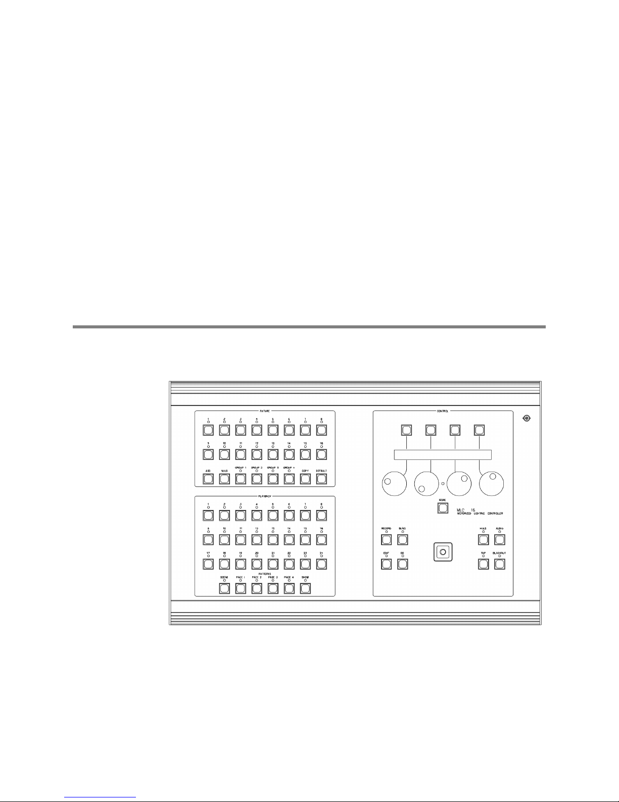
Front Panel
•
Fixture buttons (1-16).
•
Group buttons (1-4).
•
Add button.
must be the same type. Added fixtures immediately move to the exact settings
of the original fixture.
Allows you to access more than one fixture at a time. All fixtures
Allow you to access fixtures for manual live control.
Allow you to access a group for manual live control.
Leviton MLC 16D Motorized Lighting Controller Page 3 of 62
62
Page 10

User Guide
Solo button.
•
Blacks out all fixtures except the one selected. Push the button
again to return the blacked out fixtures to their proper intensities.
•
Copy button.
Copies the values of one fixture to another fixture of the same
type.
•
Default button.
When a fixture is selected, sets all parameters to the default
values assigned to that fixture personality.
•
Playback buttons (1-24).
Allow you to select scenes, patterns, and shows for
programming or playback. Use the Scene, Page 1-4 and Show buttons to
select the mode of the Playback buttons.
•
Scene button.
Places the 24 Playback buttons in Scene mode, for selecting or
programming scenes.
•
Pattern Page buttons (1-4).
Places the 24 Playback buttons in Pattern mode,
for selecting or programming patterns.
•
Show button.
Places the 24 Playback buttons in Show mode, for selecting or
programming shows.
•
Function buttons (1-4).
Allow you to select items that appear on the LCD
display.
•
Modify wheels.
•
LCD Contrast adjust.
Allow you to make changes to the items on the LCD display.
The small hole located between Modify wheels 2 and 3
allows you to adjust the contrast of the LCD display. Use a small flat-blade
screwdriver to carefully make adjustments.
• More
button.
Provides access to additional fixture traits and menu options.
Holding down this button deactivates all of a selected fixture's traits.
•
Record button.
•
Edit button.
Initiates programming of scenes, patterns, and shows.
Allows you to edit fixtures, patterns, shows, and Console Setup
menus, and exits the menus.
•
Blind button.
Allows you to modify a fixture in the blind, indicated when the
Blind LED is on. Changes made to the fixture will not appear on stage until the
Go button is pressed. The Blind function is not available in playback edit and
record modes.
•
Go button.
Advances manually stepped Patterns. If the Blind function is active,
tapping the Go button transfers any fixture changes made in the blind to the
stage.
•
Hold button.
•
Tap Sync button.
Holds the current look in a pattern or show.
Overrides any preprogrammed step times at the rate the
button is tapped.
•
Audio Sync button.
Allows audio input to override the preprogrammed step
times.
•
Blackout button.
Blacks out all fixtures to their programmed blackout values
and exits the menus.
•
Joystick.
•
Worklight.
Controls the pan and tilt of fixtures.
A BNC connector is provided for powering a standard worklight.
Page 4 of 62 Leviton MLC 16D Motorized Lighting Controller
If you encounter a problem with a front panel control, you can place the
console in Panel Test mode, which runs a diagnostic routine for
debugging the front panel hardware.
62
Page 11
User Guide
To place the console in Panel Test mode:
1
Turn the console on while pressing Pattern Page 1, Page 2, Page 3, and
Page 4 simultaneously.
Once active, the test mode sequences the front panel LEDs so you can
check for any outages.
2
Press a button or move the joystick to show its name on the LCD display.
Note:
Moving a Modify wheel increases or decreases a corresponding
number on the LCD.
3
Turn the console off to clear the Test mode.
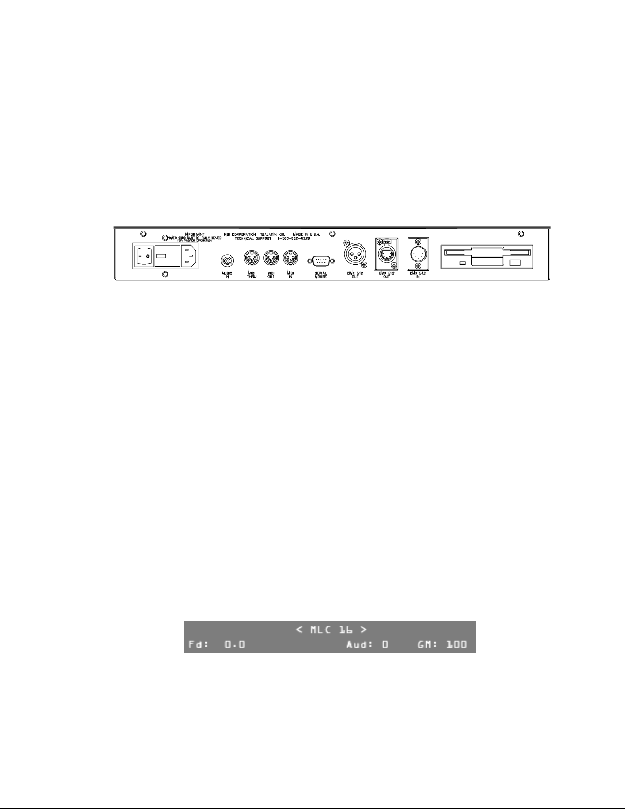
Rear Panel
•
Power switch.
•
Power in.
removable cover allows it to be reconfigured for 240 VAC operation.
•
Audio input.
shows based on the beat of the audio source.
•
MIDI In/Out/Thru.
other MIDI controller.
•
Serial Mouse
serial mouse or trackball for controlling fixture pan and tilt traits, or import
Fixture Definitions whenever the Fixture Definition Menu is active.
•
DMX512 Output.
equipment using this style of connector.
•
DMX512 Output.
equipment using this style of connector. This output conforms to the USITT
standard.
•
DMX512 Input.
with MLC 16D outputs, and pass through it.
•
Disk Drive.
console programming, and transfer programming from one console to another.
Turns console power on and off.
Connects to the female end of the supplied AC power cable. The
Accepts a line level audio signal to trigger steps in patterns and
5-pin DIN connectors connect to a MIDI sequencer or
RS-232 connector. Allows you to connect a Microsoft compatible
DMX512 output using a 3-pin XLR for connecting to
DMX512 output using a 5-pin XLR for connecting to
Allows you to import DMX512 from another console, combine
Optional 3-1/2" DOS compatible disk drive used to save and load
LCD Display
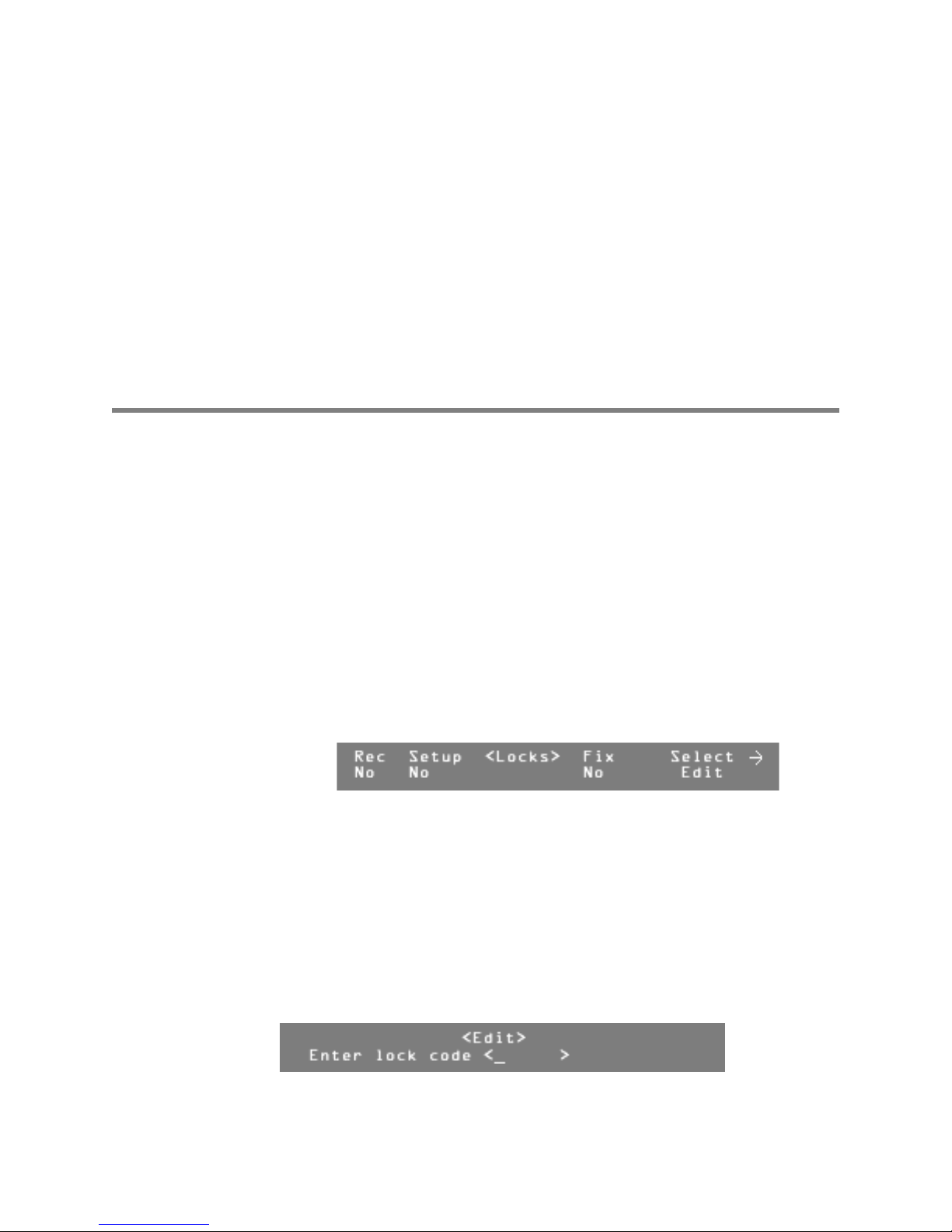
When you turn on power to the console, the LCD display shows the current
release version and build number of the software, followed by the MLC 16D Main
Screen.
The lower portion of the display shows several values that you can modify from
this screen.
•
Fd:
To set the master fade rate for all scenes played back, turn Modify wheel 1.
You can set the fade rate from 0 to 99:59.9.
Leviton MLC 16D Motorized Lighting Controller Page 5 of 62
62
Page 12

User Guide
Aud:
•
•
To adjust the audio gain, turn Modify wheel 3. Use this to fine-tune the
console's response from a line level audio signal input active in the Audio mode.
GM:
To raise or lower the console's Grand Master level, turn Modify wheel 4.
This only controls traits that are assigned to the Grand Master in the fixture's
definition. Typically this is used as a master control for all fixture dimmer traits.
All procedures in this User Guide begin at the MLC 16D Main Screen. You
can return to the MLC 16D Main Screen from any of the Record or Edit
menus by pressing Edit or Blackout.
Installation and Setup
Power Supply
The MLC 16D requires 120 VAC to operate. To turn the console on:
1
Connect the AC power cable (supplied) to a source of AC power.
2
Press the power switch located next to the power input connector.
DMX512 Input and Output
Leviton ships the MLC 16D console with two DMX512 output connectors and one
DMX512 input connector. One output connector is a standard USITT specified
5-pin female XLR. The other is a 3-pin female XLR connector used by some fixture
manufacturers. The input connector is a standard USITT specified 5-pin male XLR.
Be sure the fixture connector pin-out matches that of the MLC 16D. For
example, Martin fixtures use a 3-pin XLR, but reverses pin 2 and 3 from
the norm. Pins 2 and 3 of the 3-pin XLR can be swapped internally to
support these situations. See the chapter "3-Pin XLR Pin Reversal" for
details.
The DMX512 digital signal provides the highest speed, precision, and noise
immunity. When connecting DMX512:
• Use cable that is specified as RS-485 or RS-422 compatible (shielded, 1 or 2
twisted pair) and use the largest gauge available (22-18 gauge is good for long
runs of 1000 ft).
• Daisy chain the cable only (no star or home runs) and terminate the end of the
cable with a 120-ohm resistor. (See the fixture's manual for proper terminating
practices).
Using Audio Input
You can use a line level audio signal from an audio source such as a CD player or
mixer to trigger steps in patterns and shows based on the beat of the audio
source. When a line source is present (connected with a standard ¼-in. RCA jack)
and the Audio button LED is on, Audio mode is active and will override hold times
programmed in patterns. You can control the audio gain using the Modify wheel 3
and the LCD display. A higher value increases the gain.
Page 6 of 62 Leviton MLC 16D Motorized Lighting Controller
62
Page 13
Using the Worklight
A BNC connector is provided for powering a standard worklight. The connector
provides 12 VDC at 1A. Since the light is powered by the same supply that
provides power to the isolated DMX 512 circuit, the metal portion of the
gooseneck and lamp should not be allowed to touch the chassis ground or other
metal objects, to prevent DMX 512 interference. The lamp power is protected by
an internal fuse that will interrupt power to the lamp while retaining isolated
DMX 512 power in case of a lamp short. Consoles equipped with a Revision C or
above processor card include a built-in dimmer for varying the worklight intensity.
The dimmer control is accessed from the main menu using Modify wheel 1. F1
changes Modify wheel 1 operation from Scene fade (Fd:) to Worklight Dimmer
(Wk:). The dimmer can be varied from 0 to 100%.
Configuration
Enabling Safety Locks
The MLC 16D console allows you to set three safety locks:
•
•
•
To enable safety locks:
Record lock.
scenes, patterns, and shows.
Setup lock.
console functions. The default code is
Fixture lock.
is
abcd
1
Press the Edit button.
2
Press F4, above Setup.
3
Press F3, above Console.
4
Press the More button 5 times.
Disables the Record button and prevents recording and editing of
Prevents access to the Setup menus or the RS-232, fixture, and
Prevents access to the Fixture Define functions. The default code
.
abcd
User Guide
.
5
6
7
8
9
10
When any of the safety locks are enabled, you will be prompted to enter the lock
code when attempting to access the buttons or functions.
Leviton MLC 16D Motorized Lighting Controller Page 7 of 62
Press F4, above Edit.
Turn Modify wheel 1, below Rec to select Yes, enabling the Record lock.
Turn Modify wheel 2, below Setup, to select Yes, enabling the Setup
lock.
Turn Modify wheel 3, below Fix, to select yes, enabling the Fixture lock.
Turn Mo d i fy whee l 4 to alternate between <Save> and <Cancel>.
Press F4, above <Save> or <Cancel>, to enable or cancel changes to
the locks.
62
Page 14
User Guide
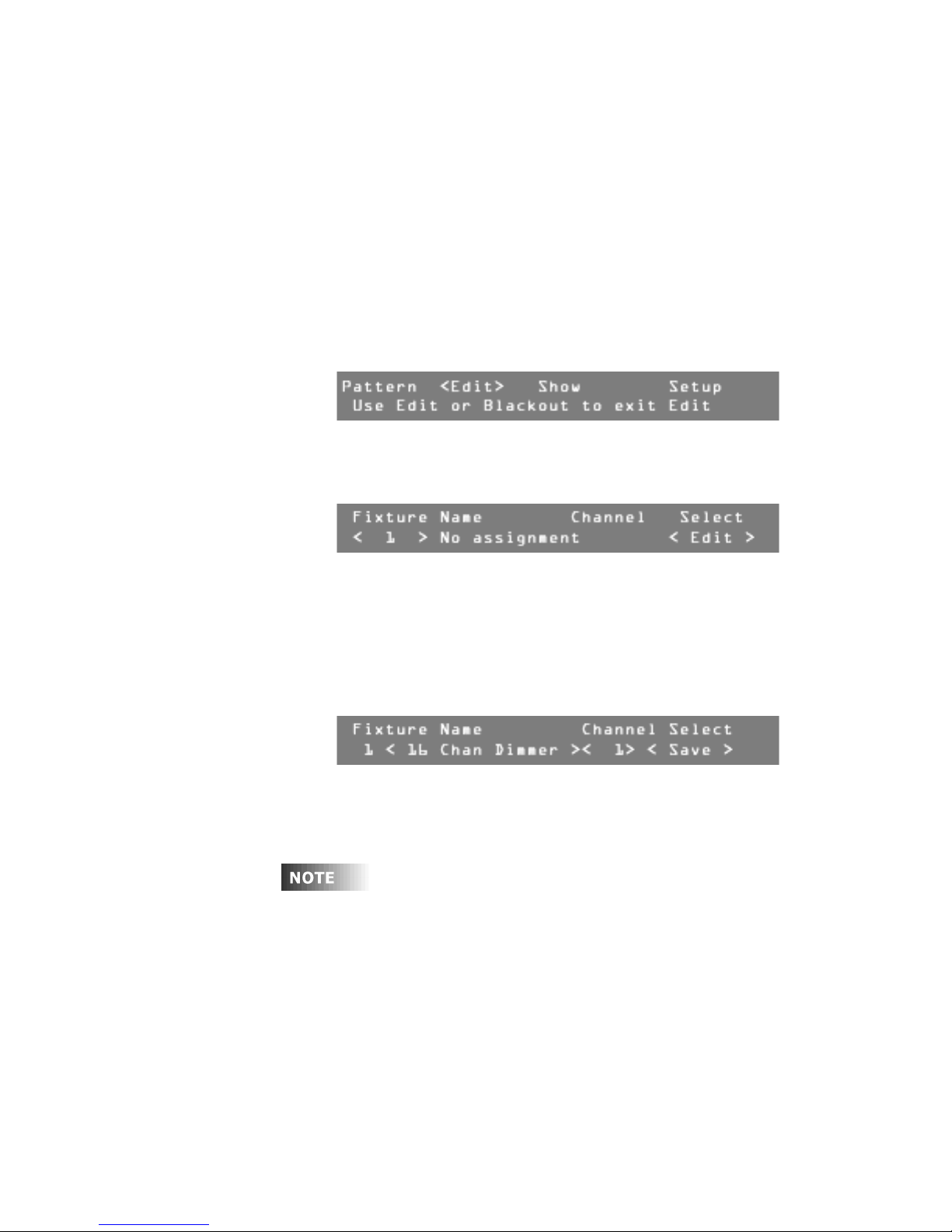
To enter the 4-digit lock code:
1
Turn Modify wheel 2 to move the cursor.
2
Turn Modify wheel 3 to change the character.
Once you have entered the lock code, the lock is released, and the menus
and/or functions are immediately available.
Assigning Fixtures
The first time you use the MLC 16D, you must assign fixture personalities to the
Select buttons corresponding to the fixtures you are using.
To assign a fixture from the Device Definition Library (DDL):
1
Press Edit.
The LCD display shows a menu of Edit commands.
2
Press F4, above Setup.
3
Press F2, above Fixture.
4
Press F3, above Assign.
5
Turn the Modify wheel 1 to select the fixture location number.
6
Press F4, above Select <Edit>.
7
Turn Modify wheel 2 to select the fixture type.
Note:
If the fixture you want to control is not in the onboard library, try to
find it in the Device Definition Library (DDL) included with the console
(see .6). If the definition is not on the DDL disk, see www.nsicorp.com.
8
Turn Modify wheel 3 to select the control channel number.
9
Press F4, above Select <Save>, to save the assignment.
The fixture has been assigned.
10
When you have made all the necessary assignments, press Edit or
Blackout to exit Edit mode.
A Fixture Overlap Error! message means that control channels
overlap, or two fixtures are on the same channel, which will cause
unexpected behavior. If this happens, calculate what the next available
channel is, by adding the number of channels the previous fixture uses to
its starting channel. This will be the next available channel for assigning a
fixture. Remember to change the starting channel on the fixture also.
To gain live control over a new fixture and verify the assignment, press the
Fixture Select button corresponding to the location where you assigned the
fixture. The LCD should show four of the fixture's traits or attributes. You can also
press and hold the Fixture Select button to view the fixture name.
Page 8 of 62 Leviton MLC 16D Motorized Lighting Controller
62
Page 15
User Guide
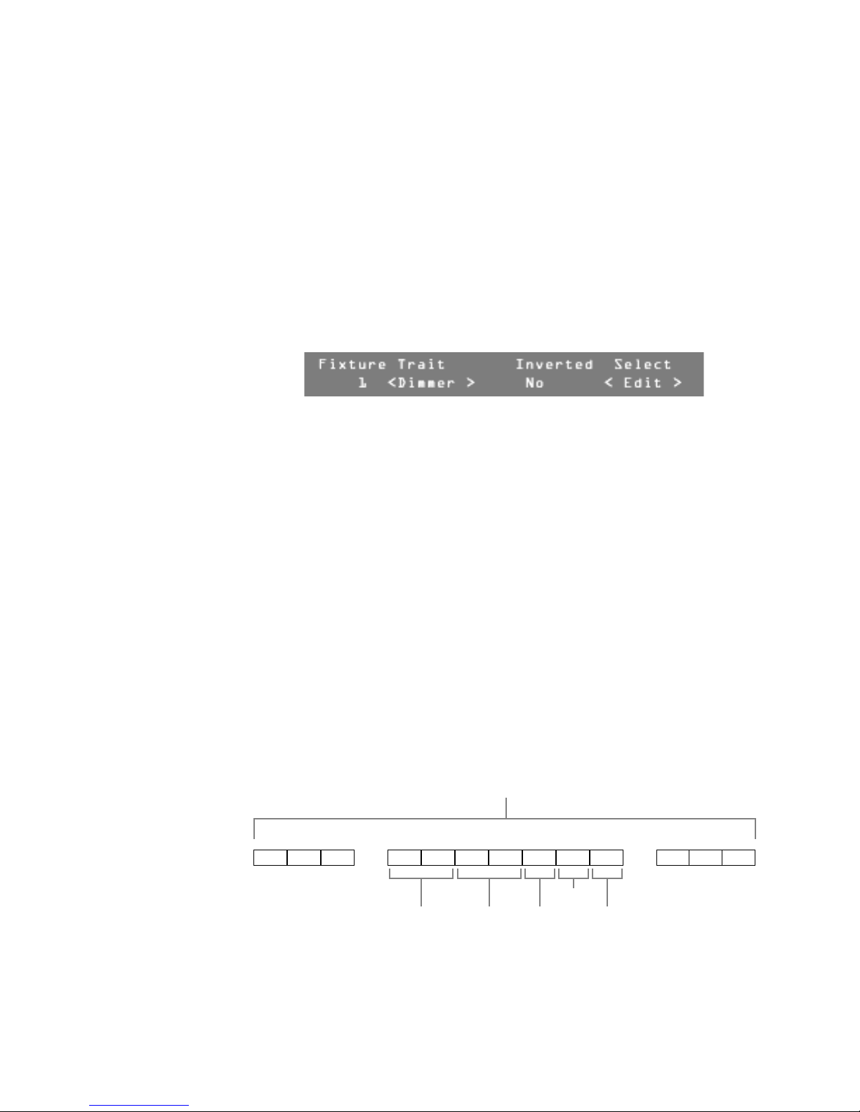
Inverting Traits
You can invert individual continuous traits of an assigned fixture using the Assign
Fixture menu. Traits of a fixture assigned to more than one Fixture button can
operate opposite from each other.
To make changes:
1
Press Edit.
2
Press F4, above Setup.
3
Press F2, above Fixture.
4
Press F3, above Assign.
5
Turn Modify wheel 4 to move from Edit to Invert.
6
Press F4, above Select <Invert>.
7
Turn Modify wheel 2 to scroll through the fixture traits.
Note:
Only continuous traits can be inverted. This inversion is in addition
to any defined within the fixture definition and will revert any trait that is
inverted in the definition. For example, if pan is inverted in the fixture
definition and then inverted again at assignment, it will operate as if it
was not inverted at all.
8
When the desired trait is shown on the LCD display, press F4, above
Select <Edit>.
9
Turn Modify wheel 3 to choose Yes or No.
10
Press F4, above Select <Save>, or turn Modify wheel 4 to Select
<Cancel> to cancel the action.
11
When you have inverted all the desired traits, press Blackout or Edit to
exit Setup mode.
Defining Fixtures
One of the keys to the ease of use of the MLC 16D is the ability to define
personalities for fixtures you wish to control. Instead of having to remember that
a fixture starts on channel 50, and that the dimmer trait is the seventh channel of
the fixture making it channel 56, you simply have to press the assigned Fixture
Select button and rotate the Modify wheel labeled Dimmer until the desired
value has been reached.
DMX512 dimmers
1 2 3 510 511 512
50 51 52 53 54 55 56
. . . . . .
Ch 1 Ch 2 Ch 3 Ch 4 Ch 5 Ch 6 Ch 7
Gobo
Pan DimmerTilt Color
Leviton MLC 16D Motorized Lighting Controller Page 9 of 62
62
Page 16
User Guide
Creating a New Fixture Definition
Many of the fixtures you use are already defined within the MLC 16D or on the
DDL floppy disk provided with the console. If not, or if you want to create a new
fixture of multiple fog machines or PAR devices for example, you need to use the
Fixture Definition Setup mode. From here you can enter a unique name for the
fixture and define the personality traits of each channel.
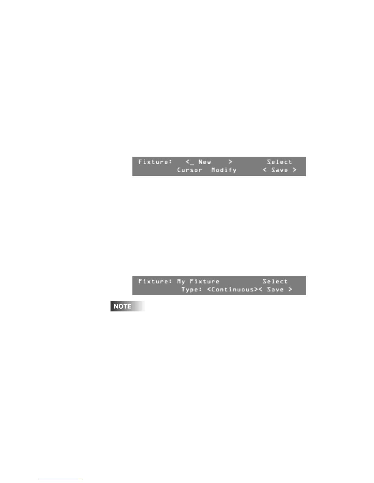
To enter the name of a new fixture:
1
Press Edit.
2
Press F1, above Setup.
3
Press F2, above Fixture.
4
Press F2, above Define.
5
Turn Modify wheel 4 clockwise to select New.
6
Press F4, above Select <New>.
You can now enter a name.
7
Turn Modify wheel 2 to move the cursor.
8
Turn Modify wheel 3 to change the character.
9
Once you have entered the name, press F4, above Select <Save>.
You are ready to add personality traits to the fixture you have named.
To add personality traits to the fixture definition:
1
Turn Modify wheel 2 until the LCD display shows the name of the desired
fixture. (If your new name appears, go directly to the next step.)
2
Turn Modify wheel 4 until the LCD display shows <Traits>.
3
Press F4, above Select <Traits>.
4
Turn Modify wheel 3 to choose Continuous, Indexed, or Union.
5
6
Page 10 of 62 Leviton MLC 16D Motorized Lighting Controller
Continuous traits move continuously from a minimum value to a
maximum value. Indexed traits do not move continuously; discrete values
are assigned to each index along with a unique label. These are most
often used to describe the positions of such things as gobo and color
wheels. Unions are made of combinations of both continuous and indexed
traits. An example of a union would be a color wheel that uses a
continuous range of DMX512 values for spins and then indexed values for
fixed color positions. The end union trait is used to flag the end of the
union structure. The console fills this in when you select a union trait. For
example, if you were to define a color wheel as described above, you
would first insert a union trait, then insert continuous and indexed traits
as needed.
Turn Modify wheel 4 until the LCD display shows <Save>.
Press F4, above Select <Save> to save the type.
Now you can assign a label to this trait.
62
Page 17

User Guide
Several attributes can be assigned to the traits once their type has been
determined. The first is a label, which can be up to eight characters long. You can
select from a table of predefined labels, or you can create your own, up to 256
possible labels.
To assign a predefined label to the traits:
1
Press F4, above Select <Edit>.
2
Turn Modify wheel 3 to select the desired label.
3
Press F4, above Select <Save>.
To create a new label for a trait:
1
Turn Modify wheel 4 to select New.
2
Press F4, above Select <New>.
3
Turn Modify wheel 2 to move the cursor.
4
Turn Modify wheel 3 to change the character.
5
Once you have entered the label name, press F4, above Select
<Save>.
It will take 5 or 6 seconds to save the new label name.
Once the label has been selected, you can assign the other attributes of a trait.
Assigning Additional Attributes to Traits
To assign additional attributes to a trait:
1
Turn Modify wheel 2 to scroll through the attributes.
2
Press F4 to edit an assignment.
3
Turn Modify wheel 3 to make the desired changes.
4
Press F4 to save the changes.
5
Continue until you have assigned all attributes for this trait.
Adjusting Continuous Trait Parameters
You can modify the following parameters for continuous traits:
•
Channel.
this trait. This is a relative number that is added on to the base address of the
fixture once it is assigned to a Fixture Select button.
•
Size.
stream. Choices are 8-Bit or 16-Bit. 16-bit is mostly used for pan and tilt of
high-resolution fixtures.
•
Invert.
direction as intended.
Determines which channel of the DMX512 stream should be used for
If fixture 1 is assigned to DMX512 channel 20 and a trait is assigned to
channel 1, it will end up being assigned to channel 20, not 21.
Determines whether the trait will use one or two channels of the DMX512
Inverts a continuous trait such as pan so that it moves in the opposite
Leviton MLC 16D Motorized Lighting Controller Page 11 of 62
Inverting can also be done at assignment time on a per trait basis.
62
Page 18

User Guide
X-axis and Y-axis.
•
Assigns a trait to the X or Y-axis of the joystick. More than
one trait of a fixture can be assigned to either axis and a single trait can be
assigned to both axes. X is usually horizontal or pan; Y is usually vertical or tilt.
•
B/O (Blackout).
Sets the trait to the assigned Blackout value whenever the
Blackout button is pressed.
•
BoValue (Blackout Value).
Assigns the value a trait is at when the Blackout
button is pressed.
•
Master.
•
Default.
Assigns a trait to the Grand Master control.
Assigns a default value to a trait; pressing the Default button causes
the default value to be applied whenever a fixture is active.
•
Max and Min.
Assigns maximum and minimum values to a continuous trait.
This is useful when a device does not use the full range of DMX512 values, or
when a continuous trait is part of a union.
Adjusting Indexed Trait Parameters
Indexed traits are made of index values, which can be changed at any time. Each
index can be assigned a specific label just as each trait can be assigned a specific
label.
You can modify the following parameters for indexed traits.
•
Channel.
this trait. This is a relative number that is added on to the base address of the
fixture once it is assigned to a Fixture Select button.
•
X-axis and Y-axis.
one trait of a fixture can be assigned to either axis and a single trait can be
assigned to both axes. X is usually horizontal or pan; Y is usually vertical or tilt.
•
B/O (Blackout).
Blackout button is pressed.
•
BoValue (Blackout Value).
button is pressed.
•
Default.
the default value to be applied whenever a fixture is active.
•
Indexes (Number of Indexes).
trait. There are a maximum of 255 indexed values that can be assigned.
•
IL1-ILX (Index Label 1-X).
labels are stored separately from the Table of Trait Labels, providing up to 896
labels to choose from or create.
•
IV1-IVX (Index Value 1-X).
Determines which channel of the DMX512 stream should be used for
Assigns a trait to the X or Y-axis of the joystick. More than
Sets the trait to the assigned Blackout value whenever the
Assigns the value a trait is at when the Blackout
Assigns a default value to a trait; pressing the Default button causes
Specifies the number of indexes used by the
Assigns a label to the specified index value. Index
Assigns a value to the specified index value.
Adjusting Union Trait Parameters
Union traits act as a header for continuous and indexed traits grouped together
on the same channel. The end of the group is marked by an end union trait. This
trait is automatically inserted when you select and insert a union trait.
You can modify the following parameters for union traits.
•
Channel.
this trait. This is a relative number that is added on to the base address of the
fixture once it is assigned to a Fixture Select button.
•
B/O (Blackout).
Blackout button is pressed.
Page 12 of 62 Leviton MLC 16D Motorized Lighting Controller
Determines which channel of the DMX512 stream should be used for
Sets the trait to the assigned Blackout value whenever the
62
Page 19
User Guide
BoValue (Blackout Value).
•
Assigns the value a trait is at when the Blackout
button is pressed.
•
Default.
Assigns a default value to a trait; pressing the Default button causes
the default value to be applied whenever a fixture is active.
Adding Additional Traits
Once you have set the attributes for your first strait, you need to add the rest of
the traits to your fixture definition.
To add additional traits:
1
Turn Modify wheel 4 until the LCD display shows <Insert>.
2
Press F4, above Select <Insert>.
Note:
When inserting or deleting fixture traits, be patient; it can take up
to several minutes for the console to complete this process.
3
Press F4, above Select <Edit>.
4
Turn Modify wheel 3 to select a label.
5
Press F4, above Select <Save>.
6
Continue adding additional traits and assigning their attributes until the
fixture is fully defined.
Assigning and Editing Groups
Fixtures that share common traits can be assigned to one of the four Group
Select buttons. Each Group Select button then becomes a kind of virtual fixture
combining the common traits and indexed labels of all the assigned fixtures.
Whenever a Group is active, the common traits of the fixture can be changed in
unison from a single control. With this release of firmware there is no longer a
limitation in controlling continuous portions of union traits in a group.
Trait labels must match exactly. Trait labels and index labels are case
sensitive. Use care when defining labels if grouping is to be used.
To create or edit a Group:
1
Press Edit.
2
Press F4, above Setup.
3
Press F2, above Fixture.
4
Press F1, above Group.
5
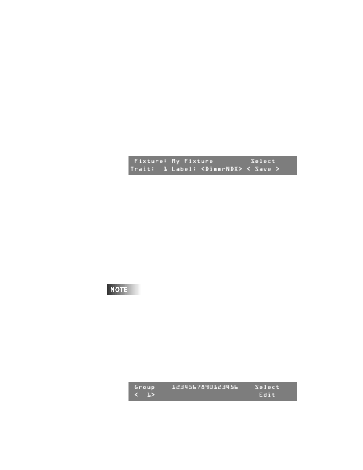
Turn Modify wheel 1 to scroll through the groups.
Currently assigned fixtures are shown with an "X" under the number of
each fixture.
6
Leviton MLC 16D Motorized Lighting Controller Page 13 of 62
When the LCD display shows the desired group, press F4, above Select
Edit.
62
Page 20
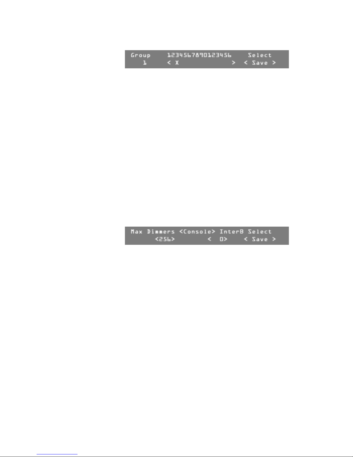
User Guide
7
Turn Modify wheel 2 to move the cursor to the fixture location.
8
Turn Modify wheel 3 to add X or remove X as needed for each location.
Note:
When there is no fixture assigned to a location, the X is inactive.
9
Continue until all your fixtures have been assigned.
10
Press F4, above Select <Save>, or turn Modify wheel 4 to Select
<Cancel> to cancel the action.
11
Continue assigning fixtures into groups, or press Blackout or Edit to exit
the Group Setup menu.
Setting the Maximum Dimmers
The MLC 16D can control up to 512 dimmers or control channels. If you are using
fewer, you should reduce the Maximum Dimmers setting to the number needed,
to prevent the console from sending needless information.
To change the Maximum Dimmers setting:
1
Press Edit.
2
Press F4, above Setup.
3
Press F3, above Console.
4
Press F4, above Select Edit.
5
Turn Modify wheel 2, under Max Dimmers, to select a value between 48
and 512.
6
Turn Modify wheel 4 to select <Save> or <Cancel>.
7
Press F4, above <Save> or <Cancel>. The action is saved or cancelled.
8
Press Blackout or Edit to exit the Console Setup menu.
Setting the Interbyte Delay
Some fixtures cannot keep up with DMX512 at full speed. This usually appears as
a momentary glitch, because the fixture has missed some data and uses incorrect
values. Putting additional time between each byte transmitted can usually
alleviate this problem.
If you are experiencing intermittent control problems, try varying the interbyte
delay. A value of 256 is the maximum delay (about 200 microseconds); 0 indicates
no delay.
To set the interbyte delay:
1
Press Edit.
2
Press F4, above Setup.
3
Press F3, above Console.
4
Press F4, above Select Edit.
5
Turn Modify wheel 3 under InterB, to select the desired value.
Page 14 of 62 Leviton MLC 16D Motorized Lighting Controller
62
Page 21

User Guide
Large values will seriously affect the efficiency of the console, especially
with large numbers of output dimmers. Therefore, first try the maximum
value to see if the problem is alleviated. If so, reduce the value as low as
possible while still achieving the benefits.
6
Turn Modify wheel 4 to select <Save> or <Cancel>.
7
Press F4, above <Save> or <Cancel>. The action is saved or cancelled.
8
Press the Blackout or Edit button to exit Console Setup menu.
Setting and Using the DMX Input Mode
In addition to broadcasting DMX512, the console can receive DMX512 signals.
When DMX Input is enabled there are two modes of operation available:
• Pass Thru mode
• 9-Channel mode
Setting DMX Input to Pass Thru Mode
Pass Thru mode allows the MLC 16D to receive DMX512 signals from other
consoles and merge those values with the output of the console. The merging of
the signals is coordinated through a "highest takes precedence" arbitration
scheme. This means that the signal source with the higher value is used.
For example, if the input signal is 50 and the channel being controlled is an 8-bit
continuous channel, the console will only be able to control values between 50
and 255. The effect is what may appear to be a restriction of the range of control
on a channel-by-channel basis.
If the input signal is lost, the input values are retained until the console is
rebooted.
To set the DMX Input mode to Pass Thru mode:
1
Press Edit.
2
Press F4, above Setup.
3
Press F3, above Console.
4
Press More.
5
Pres F4, above Select Edit.
6
Turn Modify wheel 2 under DMX In Mode, to select Pass Thru.
7
8
9
Leviton MLC 16D Motorized Lighting Controller Page 15 of 62
Turn Modify wheel 4 to select <Save> or <Cancel>.
Press F4, above <Save> or <Cancel>.
The action is saved or cancelled.
Press Blackout or Edit to exit the DMX Input Mode menu.
62
Page 22
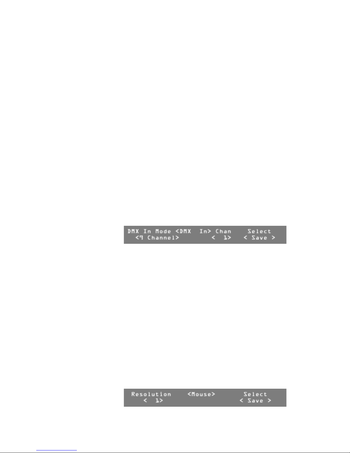
User Guide
Setting DMX Input to 9-Channel Mode
The 9-Channel mode allows nine channels to be used to trigger any scene,
pattern, show, or blackout by interpreting the values as a binary code. The
starting address for the 9-Channel mode can be adjusted anywhere within the
console's 512 control channels. Levels above 50% are considered a logical 1,
while levels less than 50% are considered a logical 0.
A zero value causes a blackout to occur. Scenes, patterns, and shows have both
on and off commands. The scenes are mapped to values 1-24 (on) and 145-168
(off), patterns to values 25-120 (on) and 170-264 (off), and shows to values 121144 (on) and 265-288 (off).
For example, to turn on pattern 40 (Playback button 16 on Pattern Page 2), the
nine channels should form this binary pattern, 000000100 (only the seventh
channel of the nine-channel frame is on; the other eight channels are off). The
lowest channel number represents the least significant bit of the binary number.
The least significant bit of the binary number is the number to the farthest left. (A
complete set of tables detailing the channel values for each event can be found in
the tables in the Appendix at the end of this manual.)
To set the DMX Input mode to 9-Channel mode:
1
Press Edit.
2
Press F4, above Setup.
3
Press F3, above Console.
4
Press More.
5
Pres F4, above Select Edit.
6
Turn Modify wheel 2 under DMX In Mode, to select 9 Channel.
7
Turn Modify wheel 3 under Chan, to select the starting number for the
block of 9 channels used in 9-Channel mode.
8
Turn Modify wheel 4 to select <Save> or <Cancel>.
9
Press F4, above <Save> or <Cancel>. The action is saved or cancelled.
10
Press Blackout or Edit to exit the DMX Input Mode menu.
Setting Mouse Resolution
A Microsoft-compatible serial mouse can be plugged into either serial port to
control pan and tilt fixture traits.
To change the mouse resolution:
1
Press Edit.
2
Press F4, above Setup.
3
Press F3, above Console.
4
Press More four times.
5
Pres F4, above Select <Edit>.
6
Turn Modify wheel 2 under Resolution, to select the desired value
(from 1 to 64).
Page 16 of 62 Leviton MLC 16D Motorized Lighting Controller
62
Page 23

User Guide
7
Turn Modify wheel 4 to select <Save> or <Cancel>.
8
Press F4, above <Save> or <Cancel>.
The action is saved or cancelled.
9
Press Blackout or Edit to exit the Mouse Resolution menu.
Entering Channel Test Mode
Channel Test mode allows you to control output channels directly. This is useful
when the traits of a fixture are not known or if index values need to be
determined.
To change the mouse resolution:
1
Press Edit.
2
Press F4, above Setup.
3
Press F2, above Fixture.
4
Press F4, above Test.
5
Press F1 through F4, until you find the DMX output channel of the fixture
you want to test.
Note:
Use F2 and F3 to decrease and increase the output channel
numbers by 1. Use F1 and F4 to decrease and increase the output
channel numbers by 10.
6
Turn Modify wheels 1 through 4 to vary the level of the output channels
above them.
7
Press Blackout or Edit to exit the Test mode menu.
Clearing and Initializing Memory
You can clear all or parts of the console's flash memory.
Clearing Scenes, Patterns, and Shows
To clear scenes, patterns, and shows:
1
Press Edit.
2
Press F4, above Setup.
3
Press F3, above Console.
4
Press More six times.
5
Press the Function button above the desired option.
-
Choose Clear All to clear all scenes, patterns, and shows.
-
Choose Clear Scene to clear all scene memory.
-
Choose Clear Pattern to clear all pattern memory.
-
Choose Clear Show to clear all show memory.
A confirmation menu appears for each of the options.
6
Press F3, above Yes, to clear or initialize the memory,
or press F4, above No, to return to the Memory menu.
7
Press Blackout or Edit to exit the Memory menu.
Leviton MLC 16D Motorized Lighting Controller Page 17 of 62
62
Page 24

User Guide
Clearing and Initializing Fixtures and MIDI
To clear scenes, patterns, and shows:
1
Press Edit.
2
Press F4, above Setup.
3
Press F3, above Console.
4
Press More seven times.
5
Press the Function button above the desired option.
-
Choose Clear Fixtures to clear the DDL, Trait and Index Label
tables, fixture, invert, and grouping assignments.
-
Choose Init Fixtures to restore the default DDL, and Trait and
Index Label tables. This will also clear all fixture, invert, and grouping
assignments.
-
Choose Clear MIDI to clear all MIDI assignments.
-
Choose Init MIDI to initialize all MIDI assignments to default values.
A confirmation menu appears for each of the options.
6
Press F3, above Yes, to clear or initialize the memory,
or press F4, above No, to return to the Memory menu.
7
Press Blackout or Edit to exit the Memory menu.
Resetting the Console
You can clear the entire console memory and install factory default parameters.
Warning!
All programming will be lost along with Fixture Definitions. Use
this procedure only if the console is known to have corrupted memory,
and clearing memory from the Console Setup menu does not solve the
problem.
To reset the console:
1
Turn off power to the console.
2
Hold down the four Function buttons above the LCD display.
3
Turn the power switch on while holding the buttons down.
4
Release the buttons once the LCD display shows the !!Initializing
Console!! message.
It will take approximately 20 seconds for the memory to clear and
initialize.
Disk Setup
Consoles equipped with a disk drive will have an additional disk menu that can be
accessed from teh Setup menu. Disk drive utilities include Format, Delete, Load,
and Save. All console programming can be saved and loaded from the disk in
binary or ASCII format. Since the disk format used is MSDOS compatible, the
ASCII formatted files can be useful for offline editing. You can write a fixture's
definition with a word processor or text editor, and load it into the console using
the disk drive. Scene and pattern step levels are saved in fixture definition form
rather than as raw numbers. To change the color of a fixture from blue to red you
just need to enter the new label. (The label must match those defined in the
fixture's definition.) The console performs the translation as the file is loaded.
Page 18 of 62 Leviton MLC 16D Motorized Lighting Controller
62
Page 25
User Guide
Refer to the “ASCII Formatting Guide” on page 36 for an explanation of the syntax
of the ASCII formatted files.
Formatting a Disk
This utility allows you to format a new disk as an MSDOS compatible disk.
Most disks sold are preformatted and will not require this operation.
To format a disk:
1
Press Edit.
2
Press F4, above Setup.
3
Press F4, above Disk.
4
Press F1, above Format.
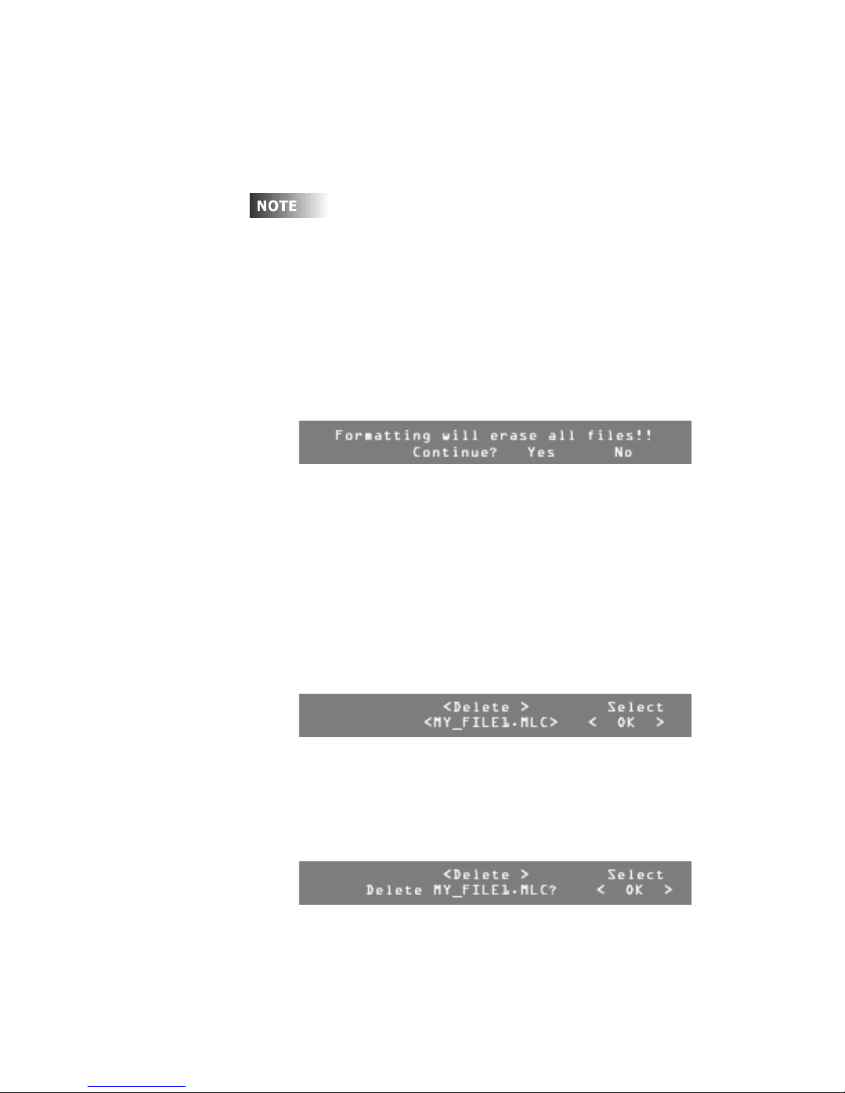
A confirmation menu appears.
5
Press F3, above Yes, to format the disk,
or press F4, above No, to return to the Disk menu.
When formatting is complete, the console returns to the Disk menu.
6
Press Blackout or Edit to exit the Disk menu.
Deleting Files on a Disk
This utility allows you to clean up a disk, deleting individual files.
To delete files on a disk:
1
Press Edit.
2
Press F4, above Setup.
3
Press F4, above Disk.
4
Press F2, above Delete.
Once the file directory is loaded, the Disk Delete menu appears.
5
Turn Modify wheel 2 or 3 to move through the list of available files.
6
Turn Modify wheel 4 to select <Save> or <Cancel>.
7
Press F4, above Select <OK>, to delete the file,
or Press F4, above Select <Cancel>, to return to the Disk menu.
If you selected
request.
8
Turn Modify wheel 4 to select <Save> or <Cancel>.
<OK>
, a confirmation menu appears to confirm your
9
10
Leviton MLC 16D Motorized Lighting Controller Page 19 of 62
Press F4, above Select <OK>, to delete the file,
or Press F4, above Select <Cancel>, to return to the Disk menu.
Press Blackout or Edit to exit the Disk menu.
62
Page 26

User Guide
Loading Files from a Disk
Use this utility to load a file from a disk. Once the directory has been loaded, you
can select the file to be loaded.
If an ASCII file contains any Fixture Definitions, a prompt appears to confirm
whether the current fixture library should be deleted. If the file contains a new full
library you should delete the current fixture library. If you are simply adding a new
fixture you should not delete the entire fixture library. The fixture library shipped
from the factory is fairly full; there will be limited space available for new Fixture
Definitions to be added. The DDL disks provided with this manual contain all the
fixtures in the console library plus some additional ones. You can reload the
deleted fixtures if they are needed later. Fixture Definitions can also be
downloaded from our Web site (www.nsicorp.com).
If the console finds an error with the ASCII file, it will report the error and line
number where the error occurred. The only way an error should occur from a file
written by the console is if the file refers to fixture definitions or assignments that
do not currently exist in the console. If the file was written or modified offline,
there is probably a syntax error.
To load a file from a disk:
1
Press Edit.
2
Press F4, above Setup.
3
Press F4, above Disk.
4
Press F3, above Load.
Once the file directory is loaded, the Disk Load menu appears.
5
Turn Modify wheel 2 or 3 to move through the list of available files to be
loaded.
6
Turn Modify wheel 4 to select <Save> or <Cancel>.
7
Press F4, above Select <OK>, to load the file,
or Press F4, above Select <Cancel>, to return to the Disk menu.
If you selected
Note:
If the file contains fixture definitions, a menu appears asking
<OK>
, the file begins loading.
whether or not to clear all fixture definitions, Trait and Index Label tables,
fixture, invert, and group assignments.
8
Press F3, above Yes, to clear the existing fixture definitions, tables, and
assignments,
or press F4, above No, to continue loading this file without clearing
existing fixture definitions, tables, and assignments.
Note:
Press F4 above Select <Cancel> at any time to stop loading a
file.
9
Press Blackout or Edit to exit the Disk Load menu.
Page 20 of 62 Leviton MLC 16D Motorized Lighting Controller
62
Page 27
User Guide
Saving Files to a Disk
You can save console information to a disk in two primary file formats:
•
ASCII.
Provides easy offline editing. Many types of console programming can
be saved in ASCII format: console configurations, fixtures, scenes, patterns,
and shows. The All option saves the console configurations, fixtures, scenes,
patterns, and shows in a single file.
•
Binary.
When a binary file is loaded all existing programming will be lost.
Refer to the “ASCII Formatting Guide” on page 36 in the Appendix for an
explanation of the syntax of the ASCII formatted files.
To save files to a disk:
Saves an exact image of all 512K bytes of the Flash EPROM memory.
1
Press Edit.
2
Press F4, above Setup.
3
Press F4, above Disk.
4
Press F4, above Save.
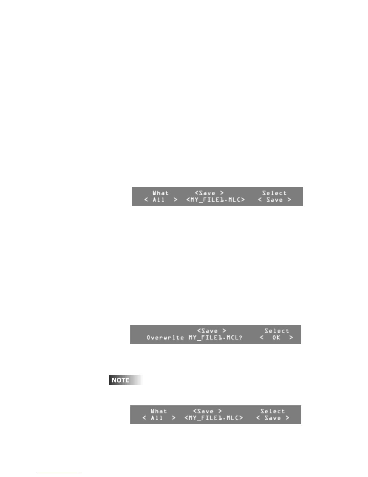
Once the file directory is loaded, the Disk Save menu appears.
5
Turn Modify wheel 2 or 3 to move through the list of available files.
6
Turn Modify wheel 1 to select the type of memory to save:
-
All
-
Configs
-
Fixtures
-
Scenes
-
Patterns
-
Shows
-
Binary.
7
Turn Modify wheel 4 to select <Save>, <New>, or <Cancel>.
8
Press F4, above one of the following options:
-
Select <Save> saves over the selected file
-
Select <New> creates a new file
-
Select <Cancel> returns to the Disk menu.
If you selected <Save>, a confirmation menu displays to confirm
overwriting the selected file.
9
Turn Modify wheel 4 to select <OK> or <Cancel>.
10
Press F4, above Select <OK>, to save over the selected file,
or press F4, above Select <Cancel>, to return to the Disk menu.
Leviton MLC 16D Motorized Lighting Controller Page 21 of 62
If you selected <New>, a menu appears asking you to fill in a file name
for the new file.
62
Page 28

User Guide
To name the new file:
1
Turn Modify wheel 2 to move the cursor.
2
Turn Modify wheel 3 to change the character.
3
Turn Modify wheel 4 to select <Save> or <Cancel>.
4
Press F4, above Select <OK>, to save the new file,
or press F4, above Select <Cancel>, to return to the Disk menu.
5
Press Blackout or Edit to exit the Disk Load menu.
Page 22 of 62 Leviton MLC 16D Motorized Lighting Controller
62
Page 29

Programming
Overview
Once you have assigned your devices and groups, you can record scenes,
patterns, and shows.
All programming is stored in non-volatile memory which retains information for at
least 10 years even when power is removed.
When recording scenes or patterns you must decide whether to record in All Traits
mode or Selective Traits mode.
All Traits Mode
When using the All Traits mode to record, the console records the full range of
available control channels (see “Setting the Maximum Dimmers” on page 14) into
that scene or pattern. This is the easiest mode for operating the console. Do not
use this recording mode if you plan to record multiple scenes into one pattern
step, or if you plan to run multiple scenes or patterns simultaneously.
Selective Traits Mode
When using the Selective Traits mode to record, only channels that are captured
or active are recorded into scenes and patterns. Use this recording mode to layer
multiple scenes into a pattern step. You can also use this recording mode to
create palettes or templates of individual traits like color or gobo that may be
activated while playing back another scene, pattern, or show to capture specific
traits.
User Guide
Once the Trait Record mode is set to All or Select, the console stays in
that mode until you turn the power off or until the mode is changed. The
factory default setting is All.
Recording Scenes
Scenes can be used by themselves as a static look, or as building blocks for
creating patterns.
Recording Scenes in All Traits Mode
To record a scene in All Traits mode:
1
Set the desired look on stage, using the Fixture or Group controls and any
previously recorded scenes.
2
Press the Record button.
3
Press F1, above Scene.
4
Turn Modify wheel 1 to select the scene to be recorded.
5
Turn Modify wheel 3 to set a fade time if desired.
Note:
This fade time will not override the master fade rate on the MLC 16
Main Screen unless you press and hold F1 while playing back or
activating a scene with a fade time.
6
Turn Modify wheel 4 to select <All>.
Leviton MLC 16D Motorized Lighting Controller Page 23 of 62
62
Page 30

User Guide
7
Press F4, above Traits <All>.
The scene is recorded.
When recording a scene in Selective Traits mode, only captured or selected traits
are recorded. This is indicated by an asterisk (*) beside the trait value in the
Device mode. To deselect or release the capture for all traits, press and hold the
More button for approximately a second. To deselect or release individual traits,
press the Function button above the trait on the LCD display. Capture the
desired trait by turning the Modify wheel below the trait or moving the joystick.
When recording a scene in Selective Traits mode, and you deselect or deactivate a
device by pressing the corresponding Select button, it is no longer active or
captured and will not be recorded into the scene. Instead you should press the
next Device button without deactivating the current one. The current Device
button LED will go out, but it is still active and will be recorded. If you accidentally
deselect any devices, you can quickly reactivate the devices in a scene by tapping
the Device Select button for each device you want in that scene.
Recording Scenes in Selective Traits Mode
To record a scene in Selective Traits mode:
1
Set the desired look on stage, using the Device buttons and any
previously recorded scenes.
2
Press the Record button.
3
Press F1, above Scene.
4
Turn Modify wheel 1 to select the scene to be recorded.
5
Turn Modify wheel 3 to select a fade time if desired.
Note:
This fade time will not override the master fade rate on the MLC 16
Main Screen unless you press and hold F1 while playing back or
activating a scene with a fade time.
6
Turn Modify wheel 4 to select <Select>.
7
Press F4, above Traits.
The scene is recorded.
Scene Record Shortcut
When no fade time is needed, you can quickly record a scene in All Traits or
Selective Traits mode:
1
Set the desired look on stage, using the Device buttons and any
previously recorded scenes.
2
Press the Record button.
3
Press the Scene button.
4
Press the Select button where you want the scene recorded.
Editing Scenes
To edit individual scenes, you must actually re-record them. However, since the
console references scenes by their location number, once you re-record a scene, it
is updated into any patterns or shows in which it has been recorded.
If you will be touring or using the MLC 16 at different venues, you can
greatly reduce setup time using the Device Position Edit capability. When
creating a pattern or show, record only the pan and tilt traits of a stage
Page 24 of 62 Leviton MLC 16D Motorized Lighting Controller
62
Page 31
User Guide
look into their own Selective Traits scene. During setup at a new venue,
re-record the new pan and tilt positions into the existing scenes and they
will update into your current patterns and shows. You can also record
these new positions as new Selective Trait scenes, allowing you to edit
them into your pattern scene steps without deleting the old positions.
Recording Patterns
There are two ways to record patterns; from previously recorded scenes, or using
manual (live) control of fixtures or groups.
Recording Patterns Using Scenes
To record a pattern from previously recorded scenes:
1
Press the Record button.
The LED on the button lights, and you enter Record mode.
2
Press F2, above Pattern.
3
Turn Modify wheel 1 to select the pattern number.
4
Turn Modify wheel 4 to select the recording mode, Select or All traits.
Note:
In general, use the same record mode that you have used to record
scenes. The same principles apply from Recording Scenes.
5
Press F4, above Traits.
Note:
If the pattern has been previously recorded, the display prompts
whether or not to delete the programming. If you select Yes or if there is
no previous programming, the LCD display prompts for the fade, hold,
and delay times of the first step.
6
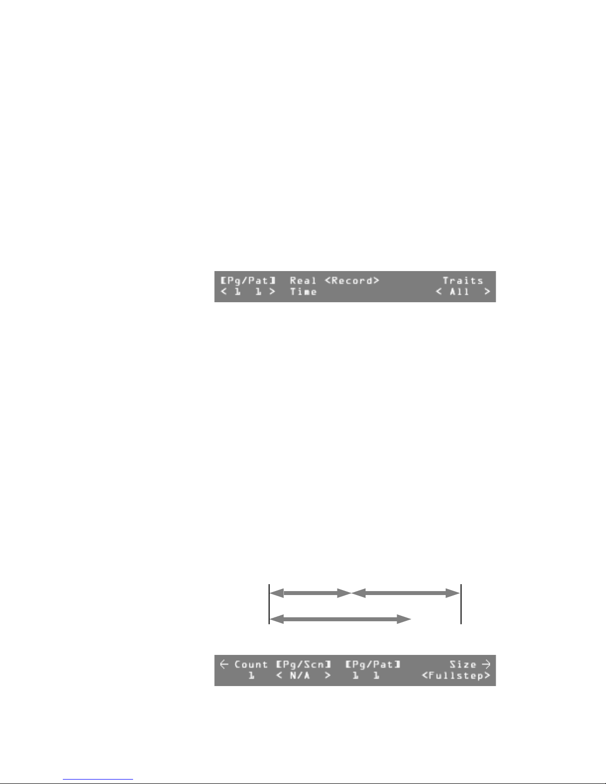
Turn Modify wheels 1, 2, and 3 to modify the fade, hold, and delay times
for this pattern step.
Note:
Fade time is the time in which the continuous channels fade from
their current positions to the positions of this step. Hold time is the time
that the faded channels hold their positions after the fade is complete.
After the hold time has timed out, the next step of the pattern will
execute. If the hold time has been set to Manual, the LED above the Go
button will begin to flash. The pattern will wait on this step until the Go
button is pressed. The delay time starts at the beginning of the step and
determines when continuous channels will change. This allows you to
delay such things as color wheel movements until later in the step rather
than right at the beginning.
7
Leviton MLC 16D Motorized Lighting Controller Page 25 of 62
Fade time Hold time
Start of
pattern step
Delay time
Press either of the More buttons.
End of step,
Start of next step
62
Page 32

User Guide
8
Turn Modify wheel 4 to select Fullstep or Scnstep.
Note:
In All Traits mode you can only record Fullsteps. In Selective Traits
mode each pattern step can have up to ten scenes layered together.
9
Turn Modify wheel 2 to select the desired scene.
Note:
In Scene Step mode, turn Modify wheel 1 to select Count 2, and
enter the next scene; continue until you have entered the desired number
of scenes.
10
Press the More buttons, then press F4, above Rec, or press the Record
button.
The step is recorded.
11
Record more steps, following this procedure.
12
When finished, press the Blackout or Edit button to exit Record mode.
Recording Patterns Using Manual Control
To record a pattern using manual (live) control of the device:
1
Press the Record button.
The LED on the button lights, and you enter Record mode.
2
Press F2, above Pattern.
3
Turn Modify wheel 1 to select the pattern to be recorded.
4
Turn Modify wheel 4 to select the recording mode, Select or All traits.
5
Press F4, above Traits.
6
Turn Modify wheels 1, 2, and 3 to modify the fade, hold, and delay times.
7
Press any of the Fixture or Group buttons for the desired device or
group.
8
Press the Select button for the desired device or group.
The LCD display shows the traits, and you have control of the fixture(s).
Note:
In the Selective Traits mode, only those traits captured (indicated
by an asterisk beside a trait value when a device is selected) will be
recorded. Whenever a device is selected with no pattern or show active,
all traits for that device are immediately captured.
9
Set the desired look on stage with all necessary groups and devices.
10
Press the Record button.
11
Repeat the previous two steps to record more pattern steps.
12
When finished, press the Blackout or Edit button to exit Record mode.
Editing Patterns
You can edit patterns to modify the scenes they contain, as well as fade, hold,
and delay times of each step, or insert or remove pattern steps.
To edit a pattern:
1
2
3
4
5
6
Page 26 of 62 Leviton MLC 16D Motorized Lighting Controller
Press the Edit button.
Press F2, above Pattern.
Turn Modify wheel 1 to select the pattern to be edited.
Press F4, above Select Edit.
Turn Modify wheel 4 to select the pattern step to edit.
Turn Modify wheels 1, 2, and 3 to modify the fade, hold, and delay times.
62
Page 33

7
Press the More button to access the scenes.
8
Turn Modify wheels 1 and 2 to change the desired scenes.
Note:
After making edits in each step, you must save them before editing
another step.
9
Press the Record button,
or press the More button two times, then F4, above Rec.
The changes to the step are saved.
10
Continue making changes to pattern steps,
or press the Blackout or Edit button to exit Edit mode.
Inserting or Deleting Pattern Steps
To insert or delete pattern steps:
1
Press the Edit button.
2
Press F2, above Pattern.
3
Turn Modify wheel 1 to select a pattern.
4
Press F4, above Edit.
5
Turn Modify wheel 4 to select the step to be deleted, or the place to insert
a step.
Note:
An inserted step will be a copy of the step selected, and will be
inserted after it. Once the new step is inserted, you can edit its content.
6
Press the More button two times.
User Guide
7
Press F2, above Insert, to add a pattern step,
or press F3, above Delete, to remove a pattern step.
8
Continue to insert and/or delete pattern steps.
9
Press the Blackout or Edit button to exit Edit mode.
Using Real Time Record
It can be difficult to know exactly what times will be best when recording a
pattern. Using the Real Time Recording mode, you can modify the times of a
prerecorded pattern in real time while, for example, the selected music is playing.
To activate the Real Time Recording mode:
1
Press the Record button.
2
Press F2, above Pattern.
3
Turn Modify wheel 1 to select the Pattern number.
4
Turn Modify wheel 4 to select All traits or Select traits.
5
Press F2, above Real Time.
Leviton MLC 16D Motorized Lighting Controller Page 27 of 62
62
Page 34
User Guide
6
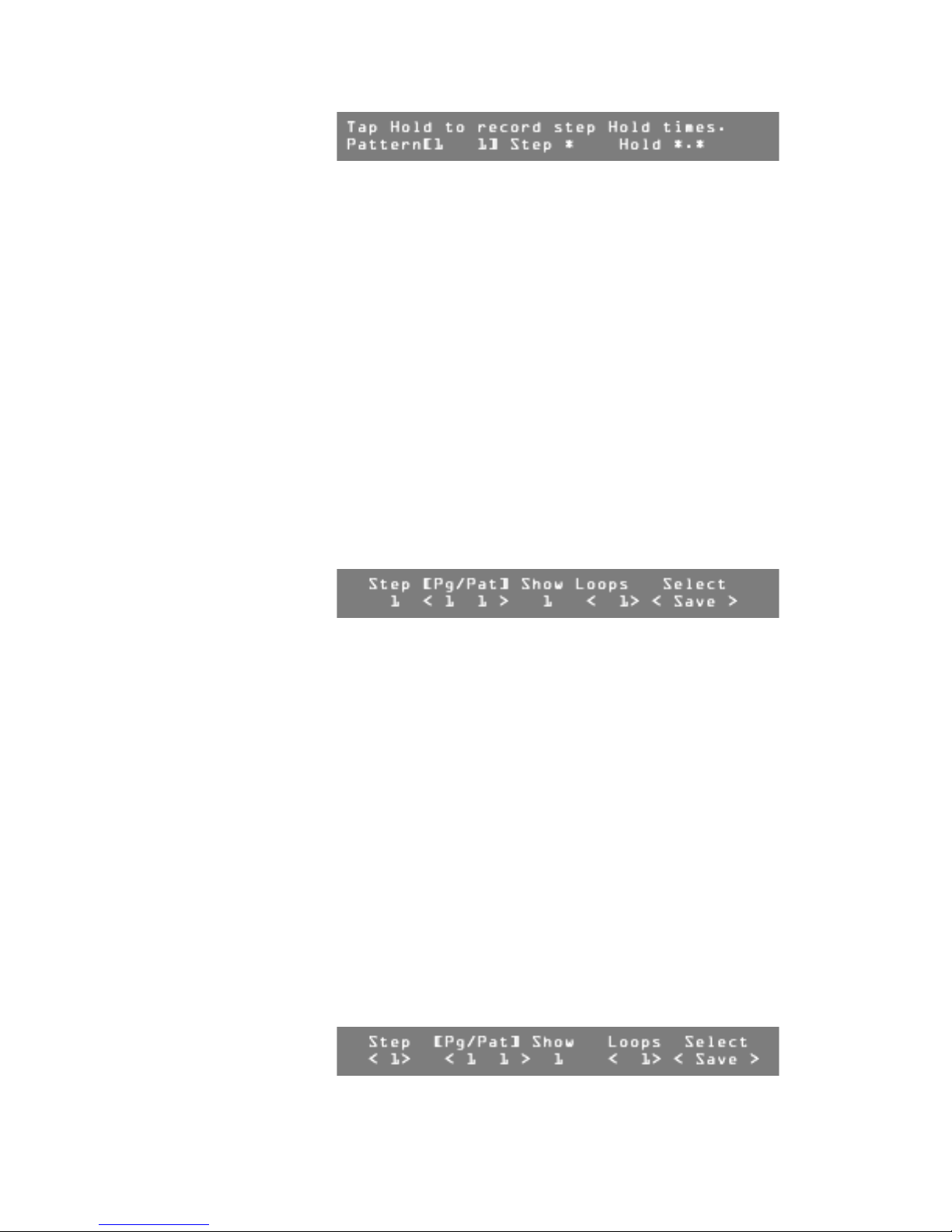
Press the Hold button to start the selected pattern running.
A timer on the LCD display starts to run.
7
When it is time to move to the next step, press the Hold button again.
The elapsed time will be used to relatively modify the stored times.
8
Continue this process until you have gone through all the steps.
The Real Time Recording mode ends once the last step is complete.
Recording Shows
You can link together patterns that have been recorded into the console to form
shows. You can record 256 shows.
To record a show:
1
Press the Record button.
2
Press F3, above Show.
3
Turn Modify wheel 1 to select the Show number.
4
Turn Modify wheel 2 to select the number of loops to be played.
Note:
You can set 1-250 loops, or infinite loops.
5
Turn Modify wheel 4 to select New.
6
Press F4, above Select.
7
Turn Modify wheel 2 to select a pattern for Step 1.
8
Turn Modify wheel 3 to select the number of loops for that pattern.
9
Turn Modify wheel 4 to select Save, Cancel, or Exit.
-
Choose <Save> to save the current show step.
-
Choose <Cancel> to return the values to their original state.
-
Choose <Exit> to return to the previous menu.
10
Press F4, above Select.
Repeat steps 7-10 until you have selected all the desired patterns.
11
Press the Blackout button to exit Record mode.
Editing Shows
To edit a show:
1
Press the Edit button.
2
Press F3, above Show.
3
Turn Modify wheel 1 to select the show to be edited.
4
Turn Modify wheel 4 until the LCD display shows Edit,
or press F4 to view the steps in the pattern.
5
Press F4, above Select <Edit>.
6
Page 28 of 62 Leviton MLC 16D Motorized Lighting Controller
Turn Modify wheel 1 to select the show step or pattern to edit.
62
Page 35

User Guide
7
Turn Modify wheel 2 to change the pattern in the step.
8
Turn Modify wheel 3 to increase or decrease the number of loops in this
step.
9
Turn Modify wheel 4 to choose an option.
-
Choose <Save> to save the changes you have made to the current
step.
-
Choose <Insert> to add a step using the current information.
-
Choose <Delete> to remove the current pattern or show step.
-
Choose <Cancel> to return the step to its originally recorded pattern.
-
Choose <Exit> to return to the last menu.
10
Press F4, above Select.
11
Press the Blackout or Edit button to exit Edit mode.
Leviton MLC 16D Motorized Lighting Controller Page 29 of 62
62
Page 36

User Guide
Playback
Once you have completed recording a scene, pattern, or show, you will want to
play it back. The basic procedures for playing scenes, patterns, or shows are
similar.
Playing Back a Scene
To activate a scene:
1
Press the Scene button.
2
Press the Select button for the desired scene.
Note:
If information is recorded, the LED on the button lights green
indicating that all channels recorded into this Scene are controlled by this
memory. If another recorded Scene button is pressed, one of two things
will happen to any other Scene LEDs that may be currently on; they will
go out or turn orange. If an LED goes out, it indicates the scene no longer
controls any of the channels recorded into it. If the LED turns orange, the
act of activating the new scene has taken control of some but not all of
the channels recorded into the scene. This gives the scene section a Last
Action takes Precedence operation style.
To reactivate a partially controlled scene (as indicated by an orange LED) press
and hold the corresponding Select button until the LED turns green, indicating
full control. If a device or group is active on the channels that the scene controls,
it may activate only partially or possibly not at all.
To release or deactivate a scene, press the corresponding Select button or press
the Blackout button.
Playing Back a Pattern
To activate a pattern:
1
Press the Pattern button.
2
Select the Page number where the pattern is located.
3
Press the Select button for the desired pattern.
The same Last Action takes Precedence operation style is applicable to
patterns.
To release or deactivate a pattern, press the corresponding Select button or
press the Blackout button.
Playing Back a Show
To activate a show:
1
Press the Show button.
2
Press the Select button for the desired show.
To release or deactivate a show, press the corresponding Select button or press
the Blackout button.
Page 30 of 62 Leviton MLC 16D Motorized Lighting Controller
62
Page 37

MIDI
User Guide
The MLC 16 allows you to use MIDI commands to activate and deactivate the
playback of scenes, patterns, and shows.
Setting the MIDI Channel
All MIDI commands sent and received by the MLC 16D use this channel number.
It can be set from 1 to 16.
To set the MIDI channel:
1
Press the Edit button.
2
Press F4, above Setup.
3
Press F3, above Console.
4
Press the More button two times.
5
Press F4, above Select Edit.
6
Turn Modify wheel 2 to select the desired MIDI channel.
7
Press F4, above Select Save.
8
Press the Blackout or Edit button to exit Setup mode.
Default MIDI Assignments
The default MIDI assignment sends a two command sequence whenever a scene,
pattern, or show is deactivated. In the following table, ranges of values are
indicated between brackets: { }.
Effect Command 1 Command 2
Scene {1...24} On Program 64 Program {0...23}
Pattern {1...24} On Program 65 Program {0...23}
Pattern {25...48} On Program 66 Program {0...23}
Pattern {49...72} On Program 67 Program {0...23}
Pattern {73...96} On Program 68 Program {0...23}
Show {1...24} On Program 69 Program {0...23}
Scene {1...24} Off Program 70 Program {0...23}
Pattern {1...24} Off Program 71 Program {0...23}
Pattern {25...48} Off Program 72 Program {0...23}
Pattern {49...72} Off Program 73 Program {0...23}
Pattern {73...96} Off Program 74 Program {0...23}
Show {1...24} Off Program 75 Program {0...23}
Blackout Program 114 None
Leviton MLC 16D Motorized Lighting Controller Page 31 of 62
62
Page 38
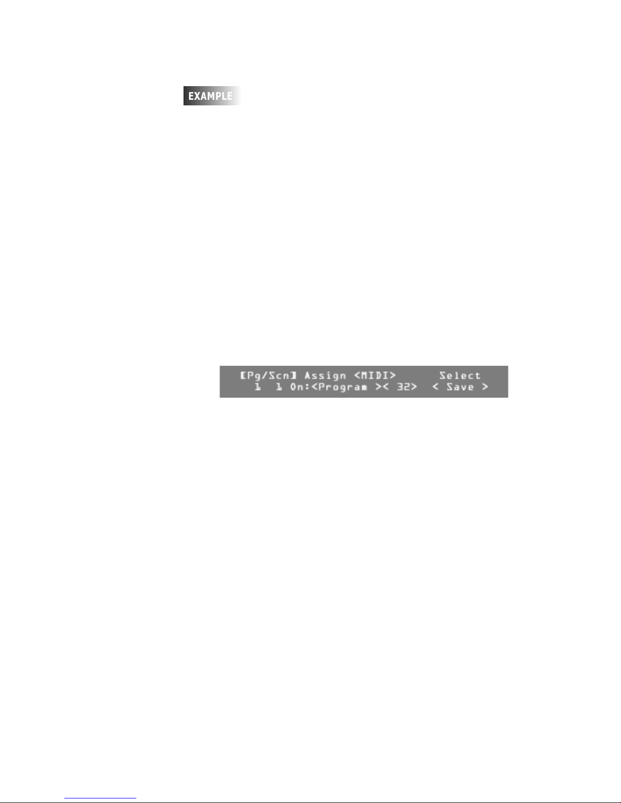
User Guide
To activate Pattern 15 of Page 4, send <PC 68><PC 14>.
<PC 68> refers to Pattern page 4; <PC 14> activates
Select
button 15.
Editing Default MIDI Command Sequences
Each scene, pattern, and show, along with the Blackout button, can have one or
two MIDI command sequences assigned to it. The commands can consist of any
combination of Note On, Note Off, Program Change and Control Change
commands. There are separate On and Off sequences for each memory, but only
one sequence for the Blackout button.
To select the item to edit:
1
Press the Edit button.
2
Press F4, above Setup.
3
Press F3, above Console.
4
Press the More button three times.
5
Turn Modify wheel 1 to select the event (scene, pattern, show, or
blackout) to edit.
6
Turn Modify wheel 2 clockwise to view the default second command.
7
Once you have selected the item to edit, press F4, above Select Edit.
8
Turn Modify wheel 1 to change the command name or to select None so
that no command is used.
Three fields are surrounded by brackets; the Command Name, the
Commands Number, and the value for Note and Control Change
commands.
9
Turn Modify wheel 2 to change the value of the Commands Number to a
value between 0 and 127.
10
Turn Modify wheel 3 to change the value for Note and Control Change
commands to a value between 0 and 127.
Note:
If you rotate past 127, Any is selected, indicating the value is not
used and any value will cause the event to trigger.
Page 32 of 62 Leviton MLC 16D Motorized Lighting Controller
62
Page 39

Troubleshooting
If you are having trouble with the MLC 16 and you have not been able to find an
answer in this guide or the checklist below, our technical support staff is available
Monday through Friday, 8:00 A.M.-5:00 P.M. PST.
NSI Technical Support: 800-864-2502.
Lockups
As with any software product, lockups can occasionally happen. While we do
everything possible to minimize these occurrences, we cannot guarantee they will
never happen. Please help us eliminate these problems by reporting them to us.
If your MLC 16 has locked up or the LCD display shows Invalid flash
memory, turn the power off and back on again. If the console does not return to
the MLC 16 Main Screen, try bypassing the Device Definition section by holding
down the More button while turning on power to the console. If this works, you
probably have a corrupted device definition. You will need to clear and initialize
the devices currently in the memory (see “Clearing and Initializing Memory” on
page 17). If the console still does not respond, you will need to reset it (see
“Resetting the Console” on page 18). This will erase all memory from the console
and return it to the factory default settings. For this reason it is important to have
a backup file of all console information.
If you can, try to reproduce the problem by repeating your actions. If you can
send us a description of how to repeat the problem we are much more likely to
solve the problem quickly.
User Guide
Bugs
A bug causes the console to behave strangely, but not lock up. If a function is
inconsistent in a particular mode but works fine otherwise, there could be a bug in
the software. If you think you have found a bug, please report it to us. We can
only fix bugs if our users tell us about them.
Reporting Problems
When you report a lockup or software bug, please include the following
information:
• Your name and contact information
• Date of the report
• Software release number (see below)
• Build number (see below)
• Whether the problem is repeatable (have you been able to consistently
reproduce the same result?)
• Description of the problem; the steps involved in producing the problem, or
what you were doing when the problem occurred (please provide as much
detail as possible)
Please fax reports to 503-404-5601 or send email to [email protected].
To find the software release and build numbers:
1
Press the Edit button.
2
Press F4, above Setup.
Leviton MLC 16D Motorized Lighting Controller Page 33 of 62
62
Page 40

User Guide
3
Press F3, above Console.
4
Press the More button eight times.
Software Updates
As we continue to update and enhance the MLC 16, new software is released.
Check our Web site (www.nsicorp.com) periodically for possible software updates.
Troubleshooting Checklist
Console will not power up. • Make sure the power supply is connected to the
console.
• Make sure the power switch is on.
Console seems to function,
but devices do not respond.
Device responds erratically. • The device may have multiple operating modes
Control exists over a device,
but it does not light.
• Make sure address setting on the device
matches the one assigned on the console.
• Check for a bad control cable by replacing it.
• Make sure the DMX512 pinout configuration is
correct for the device being used.
• Make sure the last device in the cable link has
been terminated with a terminating resistor.
and is set to one that is different from the one
defined within the MLC 16. To determine which
mode to use for the device, see the addendum
of currently defined devices (consult the factory
or visit the Web site).
• Make sure the last device in the cable link has
been terminated with a terminating resistor.
• An excessively long Interbyte Delay may be set.
• You may need a higher grade cable.
• The Grand Master may be at minimum. From
the MLC 16 Main Screen, turn Modify wheel 4,
below GM: to adjust the value.
• Some Devices need to have its lamp struck after
powerup via the DMX512 control signal. "Lamp
On" is usually an item found in the device
definition. (Press the Fixture button for the
device to gain manual control, and scroll
through the traits on the LCD using the More
button until Special appears. Turn the
corresponding Modify wheel until Lamp On
appears.)
• Check the fixture's lamp.
Page 34 of 62 Leviton MLC 16D Motorized Lighting Controller
62
Page 41

User Guide
Main LCD menu reads
!Fixture Overlap
Error!.
MLC 16 Main Screen reads
!Group Matching Found
No Matching Traits!.
MLC 16 Main Screen reads
!Group Matching
Contains No Traits To
Display!.
Scene Select button LED
lights momentarily when
button is pressed but then
goes out.
• Fixture button assignments have been made
that have resulted in traits from one device to
be assigned to the same output channels as
traits from another device. Devices almost
always control more than one output channel.
Therefore, starting channel assignments will not
be consecutive channel numbers. See
“Assigning Fixtures” on page 8.
• A Group button has been assigned Fixture
buttons that have devices assigned that have no
common trait labels. For it to be useful, a Group
should be assigned so that there is at least one
common trait label among all Fixture buttons
assigned to it.
• A Group button has been assigned Fixture
buttons that have assigned devices that only
have either pan, tilt, or both pan and tilt, in
common. The joystick or mouse will control
those channels.
• The scene has not been programmed or has
been programmed in Select mode with no traits
captured. Re-record the Scene.
Pattern Select button LED
will not turn on.
Pattern runs for awhile, then
turns off.
• The pattern has not been programmed.
• The LED may be out. Try the Panel Test to
verify.
• The pattern has a step recorded with no trait
included. This can result during editing of a
pattern if a step is inserted and then not
recorded.
Leviton MLC 16D Motorized Lighting Controller Page 35 of 62
62
Page 42

User Guide
Appendix
ASCII Formatting Guide
Overview
General ASCII formats (standard text files) allow data to be easily read and
modified on a computer using a text editor. However, in order for the information
to be understood by the console, certain rules must followed. These rules form
the syntax that is used by the MLC 16 to describe its programming. By following
these rules, you can write your own programming or device definitions offline and
load them into the console through the RS-232 port.
The general syntax for ASCII formats is as follows:
• Only one command per line.
• Lines are terminated by a carriage return or a carriage return/line feed
combination.
• All commands start with a keyword, which can be prefaced by spaces or tabs.
• Keywords are not case sensitive.
• All keywords, except "End", are followed by a value. The keyword and value are
separated by a space(s).
• Any text following a semicolon is ignored. This allows a file created with a text
editor to contain comments. Comments are not retained within the console.
Device Definition Language
The Device Definition Language (DDL) is used to describe an object's personality,
which is controlled by the MLC 16. Devices can include intelligent lighting fixtures,
fog machines, traditional luminerie/color scroller combinations or simply a series
of dimmer channels. Through the use of DDL, the MLC 16 can present the
individual attributes or traits of the personality with descriptive labels rather than
simple channel numbers as with a standard lighting console.
You can program Device Definitions into the MLC 16 two ways:
• Program it directly on the console using the Device Define utility of the Setup
menu.
• Import it into the console through either the disk driver or the RS-232 port. The
last line of the file must contain the key word End. This flags the console that
the file is complete; without it the last trait of the definition is lost.
Keyword Valid Values Description Example
Device 16-character
text string
Trai t 8- charac t e r text
string
Type Un i o n,
EndUnion,
Continuous,
Indexed
Defines the name of the
device.
Defines the text label of
the trait.
Defines the type of the
trait.
Device Scanner
Trait Pan
Type Indexed
Page 36 of 62 Leviton MLC 16D Motorized Lighting Controller
62
Page 43

User Guide
Keyword Valid Values Description Example
Channel 1-256 Defines the channel
offset of the trait.
Size 8bit, 16bit Defines the trait as 8 bit
or 16 bit. Only used in
continuous types.
Invert Yes, No Causes the joystick or a
wheel to work opposite
of normal when
controlling the trait.
XAxis Yes, No Assigns the trait to the
horizontal movement of
the joystick.
YAxis Yes, No Assigns the trait to the
horizontal movement of
the joystick.
Black Yes, No Assigns the trait to the
Blackout button.
BoValue 8 bit: 0-255
16 bit: 0-65,535
Defines the value that
the Blackout button
assigns to the trait.
Channel 8
Size 8Bit
Invert Yes
XAxis Yes
YAxis No
Black No
BoValue 0
Master Yes, No Assigns the trait to the
Master Wheel.
Default 8 bit: 0-255
16 bit: 0-65,535
Defines the value that
the Default button
assigns to the trait.
Maximum 8 bit: 0-255
16 bit: 0-65,535
Defines the maximum
value of a continuous
trait.
Minimum 8 bit: 0-255
16 bit: 0-65,535
Defines the minimum
value of a continuous
trait.
Index 8-character text
string followed
by a comma
and a value
Defines the text label
and its value of an index
entry of an indexed type
trait.
ranging from
0-255
End None Defines the end of the
file. Only required for
RS-232 input files.
Master No
Default 128
Maximum 255
Minimum 0
Index Red,30
A new device definition is initiated and named with the Device keyword.
Keywords on following lines define the traits of that device.
Leviton MLC 16D Motorized Lighting Controller Page 37 of 62
62
Page 44

User Guide
Each trait can be one of four types; continuous, indexed, union, or end union. Use
continuous types for traits, such as pan or dimmer, that use the full range of
DMX512 values. Use indexed types for traits that only use specific DMX512 values
or use a ranges of values that cause no change to the trait. Examples of indexed
types include color or gobo wheels.
The last two types, union and end union, form a pair which, used together, frame
a sequence of continuous and indexed types. This sequence allows a single trait
to take on the characteristics of both continuous and indexed types. A common
example of a union structure would be a color wheel that provides a continuous
movement range and also a "snap to color" indexed range. Once assigned and
activated, the MLC 16D compares the current value of the trait to values defined
by the traits within the union/end union structure until a match is found. If no
match is found, the actual value is displayed, placed in brackets. Turning the
wheel that controls the union trait will sequence through the values of the current
trait in the structure. Once the last value is reached and the wheel is rotated
again, control is transferred to the next trait in the structure. This passing of
control from one trait to trait continues until the end of the structure is reached.
Following is an example of an intelligent device called "Scanner." It has five traits;
pan, tilt, color, gobo and dimmer. Pan, tilt and dimmer are continuous examples.
Gobo is an indexed type example. Color is defined such that there are four values
(0,30,60,90) that position the wheel to specific colors and a range of values (100-
255) that continuously moves the wheel through all the colors. By using a union/
end union trait type combination, you can maintain all the functionality on one
wheel. An indexed type is used within the union/end union structure to define the
four color positions with descriptive labels (white, red, blue and yellow), followed
by a continuous type that defines the continuous scrolling of the wheel.
Device Name Device Scanner
Pan Trait Pan
Type Continuous
Channel 1
Size 8Bit
Invert No
XAxis Yes
YAxis No
Black No
BoValue 0
Master No
Default 128
Maximum 255
Minimum 0
Tilt Trait Tilt
Type Continuous
Channel
2
Size 8Bit
Invert No
XAxis No
YAxis Yes
Black No
BoValue 0
Master No
Default 128
Maximum 255
Minimum 0
Page 38 of 62 Leviton MLC 16D Motorized Lighting Controller
62
Page 45

Color Trait Color
Type Union
Channel 3
Black No
BoValue 0
Default 0
Trait Color
Type Indexed
Index White,0
Index Red,30
Index Blue,60
Index Yellow,90
Trait Clr
Type Continuous
Maximum 255
Minimum 100
Trait Color
Type EndUnion
Gobo Trait Gobo
Type Indexed
Channel 4
Black No
BoValue 0
Default 0
Index Open,0
Index
Stars,30
Index Circle,60
Index Triangle,90
Index Dot,120
Index Dots,150
Dimmer Trait Dimmer
Type Continuous
Channel 5
Size 8Bit
Invert No
XAxis No
YAxis No
Black Yes
BoValue 0
Master Yes
Default 255
Maximum 255
Minimum 0
End
User Guide
The MLC 16 LCD display shows traits in the order they are defined. Traits assigned
to either axis of the joystick are not displayed. It is possible to define more than
one trait for the same channel. This can be useful if you would like to have pan
and tilt on both the LCD and the joystick. Simply define two pan traits and two tilt
traits. Set them up exactly the same except that one is assigned to the joystick
and one is not.
Following is a diagram of what the LCD display shows if the above definition is
assigned and activated with a Fixture button with all output channels currently
set to zero.
Leviton MLC 16D Motorized Lighting Controller Page 39 of 62
62
Page 46
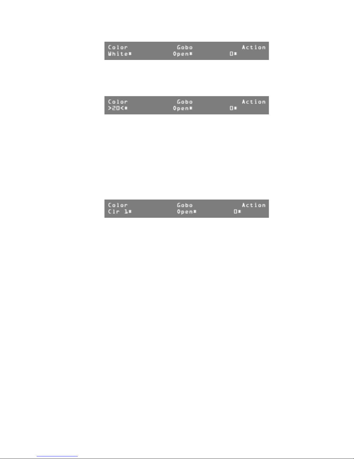
User Guide
The asterisks indicate that the traits are captured.
If the Color trait had been set to a value that is not defined by the union
structure, the console displays the actual value encased in brackets as shown
here.
A continuous type within a union/end union structure uses its label as part of the
trait's value label. This makes it possible to identify multiple continuous traits
within one union/end union trait. Labels should be kept to a maximum of four
characters since an offset value is displayed after the label to indicate the position
within the range. In this example the top line of the LCD display shows Color,
the union label. Clr, the continuous label, is shown just below the trait label
followed by a number starting at 1 and continuously incrementing to 156
(max(255) - min(100) + 1 = 156).
Once Modify wheel 1 has been used to change the color trait to Yellow, turning
it once more clockwise causes control to be transferred to the continuous portion
of the union/end union structure. The display looks like this:
Page 40 of 62 Leviton MLC 16D Motorized Lighting Controller
62
Page 47

Device Assignment Formats
Keyword Valid Values Description
User Guide
FixAssign 1-16 followed by a device
name, comma and
channel offset
Group 1-4 Establishes Group number for
GroupFix 1-16 Defines a Fixture button to a
MaxDims 49-512 Maximum number of dimmers
InterB 0-256 DMX512 interbyte delay.
DMX IM Mod Off, PassThru, 9 channel DMX512 Input mode.
DMX In Ch 1-504 Starting channel for 9 channel
Rlock Yes, No Record lock.
Slock Yes, No Setup lock.
Flock Yes, No Fixture lock.
MidiCh 1-16 MIDI channel.
Assigns devices to Fixture
buttons.
group assigning.
group.
output.
DMX512 Input.
MidiScn 1-24 Establishes Scene number for MIDI
command assigning.
MidiPat 1-96 Establishes Pattern number for
MIDI command assigning.
MidiShw 1-24 Establishes Scene number for MIDI
command assigning.
Leviton MLC 16D Motorized Lighting Controller Page 41 of 62
62
Page 48

User Guide
Keyword Valid Values Description
On
Off
Non, Noff, CC: followed
by a comma, followed by
a number 0-127,
followed by a comma,
followed by a value
0-127 or “Any.”
PC: followed by a
comma, followed by a
number 0-127.
Non, Noff, CC: followed
by a comma, followed by
a number 0-127,
followed by a comma,
followed by a value
0-127
PC: followed by a
comma, followed by a
number 0-127
Assigns a MIDI On command to a
MIDI event.
Assigns a MIDI Off command to a
MIDI event.
Scene Formats
Keyword Valid Values Description
Scene 1-24 Establishes scene number to be programmed.
Fade 0-27:00.0 Determines the scene fade time.
Traits All, Select Determines whether all traits or only those
referenced are flagged for control.
Fixture 1-16 Establishes fixture number for which following
trait values are to be applied.
T: Trai t l abel
followed by a
comma,
followed by a
valid numerical
value of label.
Following is an example of a Scene file in ASCII format. Assume that the Scanner
definition established in the DDL section has been assigned to Fixture buttons 1
and 2.
Scene 1
Traits All
fixture 1 ;Scanner
T: Pan,150
T: Tilt,30
T: Color,White
T: Gobo,Open
T: Dimmer,255
Assigns a trait value to a scene channel.
Page 42 of 62 Leviton MLC 16D Motorized Lighting Controller
62
Page 49

User Guide
fixture 2 ;Scanner
T: Pan,100
T: Tilt,75
T: Color,White
T: Gobo,Open
T: Dimmer,255
Scene 2
Traits All
fixture 1 ;Scanner
T: Pan,200
T: Tilt,187
T: Color,White
T: Gobo,Open
T: Dimmer,255
fixture 2 ;Scanner
T: Pan,120
T: Tilt,25
T: Color,White
T: Gobo,Open
T: Dimmer,255
Scene 9
Traits Select
fixture 1 ;Scanner
T: Color,Red
fixture 2 ;Scanner
T: Color,Red
Scene 10
Traits Select
fixture 1
;Scanner
T: Color,Blue
device 2 ;Scanner
T: Color,Blue
Scene 11
Traits Select
fixture 1 ;Scanner
T: Color,Yellow
fixture 2 ;Scanner
T: Color,Yellow
Scenes 1 and 2 program all traits for the two Scanners. Scenes 9 - 11 program
only color and can be used to modify the color of Scene 1 or 2. All other traits
remain unchanged. The ;Scanner string after the device number is a comment
for reference that is output from the console.
Leviton MLC 16D Motorized Lighting Controller Page 43 of 62
62
Page 50

User Guide
Pattern Formats
Keyword Valid Values Description
Pattern 1-96 Establishes Pattern number to be programmed.
Step 1-808 Establishes Step number to be programmed.
StepType FullStep,
ScnStep
Traits All, Select Determines whether all traits or only those
Scene 0-24 Attaches a scene memory to a pattern step.
Fade 0-27:00.0 Determines the pattern step fade time.
Hold 0-27:00.0 Determines the pattern step hold time.
Delay 0-27:00.0 Determines the pattern step delay time.
Fixture 1-16 Establishes fixture number for which following
T: Trait lab e l
followed by a
comma,
followed by a
valid numerical
value or label.
Following is an example of a Pattern file in ASCII format. Assume that the Scanner
definition established in the DDL section has been assigned to Fixture buttons 1
and 2. Step 1 is a full step, step 2 is a full step with a scene (17) attached and
step 3 is a scene step.
Pattern 1
Step 1
StepType FullStep
Traits All
Fade 1.0
Hold 0
Delay 0
Scene 0
fixture 1 ;Scanner
T: Pan,25
T: Tilt,30
T: Color,Clr 100
T: Gobo,Dots
T: Dimmer,255
fixture 2 ;Scanner
T: Pan,240
Determines if Full Step or Scene Step.
referenced are flagged for control.
0=No Step.
trait values are to be applied.
Assigns a trait value to a pattern step channel.
Page 44 of 62 Leviton MLC 16D Motorized Lighting Controller
62
Page 51

T: Tilt,30
T: Color,Yellow
T: Gobo,Dots
T: Dimmer,255
Step 2
StepType FullStep
Traits All
Fade 1.0
Hold 0
Delay 0
Scene 17
fixture 1 ;Scanner
T: Pan,150
T: Tilt,100
T: Color,Clr 100
T: Gobo,Dots
T: Dimmer,255
fixture 2 ;Scanner
T: Pan,150
T: Tilt,100
T: Color,Yellow
T: Gobo,Dots
T: Dimmer,255
Step 3
StepType ScnStep
Traits All
Fade 1.0
Hold 0
Delay 0
Scene 1
Scene 11
Scene 16
Scene 20
Scene 23
fixture 1 ;Scanner
T: Pan,240
T: Tilt,30
T:
Color,Clr 100
T: Gobo,Dots
T: Dimmer,255
fixture 2 ;Scanner
T: Pan,25
T: Tilt,30
T: Color,Yellow
T: Gobo,Dots
T: Dimmer,255
User Guide
Leviton MLC 16D Motorized Lighting Controller Page 45 of 62
62
Page 52

User Guide
Show Formats
Keyword Valid Values Description
Show 1-24 Establishes Pattern number to be programmed.
Loop 1-250, Infinite Determines the number of times the show will
loop until it extinguishes itself.
Step 1-24 Establishes Step number to be programmed.
PatNum 1-96 Determines the Pattern number that will run
during a show step.
Times 1-250 Determines the number of times the pattern
will loop within the show step.
Following is an example of a Show file in ASCII format. This Show has four steps
and will loop through them ten times. Step 1 runs Pattern 1 four times, step 2
runs Pattern 2 five times, step 3 runs Pattern 80 two hundred times and step 4
runs Pattern 20 ten times.
Pattern 1
Loop 10
Step 1
PatNum 1
Times 4
Step 2
PatNum 2
Times 5
Step 3
PatNum 80
Times 200
Step 4
PatNum 20
Times 10
Page 46 of 62 Leviton MLC 16D Motorized Lighting Controller
62
Page 53

Tables
User Guide
DMX Input Blackout
Chan 1 Chan 2 Chan 3 Chan 4 Chan 5 Chan 6 Chan 7 Chan 8 Chan 9
Blackout
* = channel at full, all others at minimum
Leviton MLC 16D Motorized Lighting Controller Page 47 of 62
62
Page 54

User Guide
DMX Input Scenes 1-24 On
Chan 1 Chan 2 Chan 3 Chan 4 Chan 5 Chan 6 Chan 7 Chan 8 Chan 9
Scene 1 On *
Scene 2 On *
Scene 3 On * *
Scene 4 On *
Scene 5 On * *
Scene 6 On * *
Scene 7 On * * *
Scene 8 On *
Scene 9 On * *
Scene 10 On * *
Scene 11 On * * *
Scene 12 On * *
Scene 13 On * * *
Scene 14 On * * *
Scene 15 On****
Scene 16 On *
Scene 17 On * *
Scene 18 On * *
Scene 19 On * * *
Scene 20 On * *
Scene 21 On * * *
Scene 22 On * * *
Scene 23 On * * * *
Scene 24 On * *
* = channel at full, all others at minimum
Page 48 of 62 Leviton MLC 16D Motorized Lighting Controller
62
Page 55

DMX Input Scenes 1-24 Off
Chan 1 Chan 2 Chan 3 Chan 4 Chan 5 Chan 6 Chan 7 Chan 8 Chan 9
Scene 1 Off * * *
Scene 2 Off * * *
Scene 3 Off * * * *
Scene 4 Off * * *
Scene 5 Off * * * *
Scene 6 Off * * * *
Scene 7 Off * * * * *
Scene 8 Off * * *
Scene 9 Off * * * *
Scene 10 Off * * * *
Scene 11 Off * * * * *
User Guide
Scene 12 Off * * * *
Scene 13 Off * * * * *
Scene 14 Off **** *
Scene 15 Off***** *
Scene 16 Off * *
Scene 17 Off * * *
Scene 18 Off * * *
Scene 19 Off * * * *
Scene 20 Off * * *
Scene 21 Off * * * *
Scene 22 Off * * * *
Scene 23 Off * * * * *
Scene 24 Off * *
* = channel at full, all others at minimum
Leviton MLC 16D Motorized Lighting Controller Page 49 of 62
62
Page 56

User Guide
DMX Input Patterns 1-24 On
Chan 1 Chan 2 Chan 3 Chan 4 Chan 5 Chan 6 Chan 7 Chan 8 Chan 9
Pattern 1 On * * *
Pattern 2 On * * *
Pattern 3 On** **
Pattern 4 On ***
Pattern 5 On* ***
Pattern 6 On ****
Pattern 7 On*****
Pattern 8 On *
Pattern 9 On * *
Pattern 10 On * *
Pattern 11 On * * *
Pattern 12 On * *
Pattern 13 On * * *
Pattern 14 On * * *
Pattern 15 On*** *
Pattern 16 On * *
Pattern 17 On * * *
Pattern 18 On***
Pattern 19 On****
Pattern 20 On * * *
Pattern 21 On****
Pattern 22 On *** *
Pattern 23 On**** *
Pattern 24 On * *
* = channel at Full, all others at minimum
Page 50 of 62 Leviton MLC 16D Motorized Lighting Controller
62
Page 57

DMX Input Patterns 25-48 On
Chan 1 Chan 2 Chan 3 Chan 4 Chan 5 Chan 6 Chan 7 Chan 8 Chan 9
Pattern 25 On * * *
Pattern 26 On * * *
Pattern 27 On** **
Pattern 28 On * * *
Pattern 29 On****
Pattern 30 On ** **
Pattern 31 On*** **
Pattern 32 On ***
Pattern 33 On* ***
Pattern 34 On * ***
Pattern 35 On** ***
User Guide
Pattern 36 On ****
Pattern 37 On* ****
Pattern 38 On *****
Pattern 39 On******
Pattern 40 On *
Pattern 41 On * *
Pattern 42 On * *
Pattern 43 On * * *
Pattern 44 On * *
Pattern 45 On * * *
Pattern 46 On * * *
Pattern 47 On*** *
Pattern 48 On * *
* = channel at full, all others at minimum
Leviton MLC 16D Motorized Lighting Controller Page 51 of 62
62
Page 58

User Guide
DMX Input Patterns 49-72 On
Chan 1 Chan 2 Chan 3 Chan 4 Chan 5 Chan 6 Chan 7 Chan 8 Chan 9
Pattern 49 On***
Pattern 50 On * * *
Pattern 51 On * * * *
Pattern 52 On * * *
Pattern 53 On * * * *
Pattern 54 On *** *
Pattern 55 On**** *
Pattern 56 On * *
Pattern 57 On * * *
Pattern 58 On * * *
Pattern 59 On * * * *
Pattern 60 On ***
Pattern 61 On****
Pattern 62 On****
Pattern 63 On*****
Pattern 64 On * * *
Pattern 65 On * * * *
Pattern 66 On****
Pattern 67 On** ** *
Pattern 68 On *** *
Pattern 69 On* *** *
Pattern 70 On **** *
Pattern 71 On***** *
Pattern 72 On * *
* = channel at full, all others at minimum
Page 52 of 62 Leviton MLC 16D Motorized Lighting Controller
62
Page 59

User Guide
DMX Input Patterns 73-96 On
Chan 1 Chan 2 Chan 3 Chan 4 Chan 5 Chan 6 Chan 7 Chan 8 Chan 9
Pattern 73 On * * *
Pattern 74 On * * *
Pattern 75 On** **
Pattern 76 On * * *
Pattern 77 On * * * *
Pattern 78 On ** **
Pattern 79 On*** **
Pattern 80 On * * *
Pattern 81 On * * * *
Pattern 82 On****
Pattern 83 On*****
Pattern 84 On ** **
Pattern 85 On*****
Pattern 86 On *** **
Pattern 87 On**** **
Pattern 88 On ***
Pattern 89 On* ***
Pattern 90 On * ***
Pattern 91 On** ***
Pattern 92 On * ***
Pattern 93 On* * ***
Pattern 94 On ** ***
Pattern 95 On*** ***
Pattern 96 On ****
* = channel at full, all others at minimum
Leviton MLC 16D Motorized Lighting Controller Page 53 of 62
62
Page 60

User Guide
DMX Input Patterns 1-24 Off
Chan 1 Chan 2 Chan 3 Chan 4 Chan 5 Chan 6 Chan 7 Chan 8 Chan 9
Pattern 1 Off* ***
Pattern 2 Off****
Pattern 3 Off*****
Pattern 4 Off ****
Pattern 5 Off*****
Pattern 6 Off*****
Pattern 7 Off**** * *
Pattern 8 Off * * *
Pattern 9 Off * * * *
Pattern 10 Off * * * *
Pattern 11 Off * * * * *
Pattern 12 Off * * * *
Pattern 13 Off*****
Pattern 14 Off*****
Pattern 15 Off*** ** *
Pattern 16 Off * * * *
Pattern 17 Off * * * * *
Pattern 18 Off * * * * *
Pattern 19 Off * * * * * *
Pattern 20 Off **** *
Pattern 21 Off* **** *
Pattern 22 Off ***** *
Pattern 23 Off****** *
Pattern 24 Off * *
* = channel at full, all others at minimum
Page 54 of 62 Leviton MLC 16D Motorized Lighting Controller
62
Page 61

User Guide
DMX Input Patterns 25-48 Off
Chan 1 Chan 2 Chan 3 Chan 4 Chan 5 Chan 6 Chan 7 Chan 8 Chan 9
Pattern 25 Off * * *
Pattern 26 Off * * *
Pattern 27 Off * * * *
Pattern 28 Off * * *
Pattern 29 Off * * * *
Pattern 30 Off * * * *
Pattern 31 Off*** **
Pattern 32 Off * * *
Pattern 33 Off * * * *
Pattern 34 Off * * * *
Pattern 35 Off * * * * *
Pattern 36 Off * * * *
Pattern 37 Off* ** **
Pattern 38 Off *** **
Pattern 39 Off**** **
Pattern 40 Off * * *
Pattern 41 Off * * * *
Pattern 42 Off * * * *
Pattern 43 Off * * * * *
Pattern 44 Off * * * *
Pattern 45 Off*****
Pattern 46 Off * * * * *
Pattern 47 Off * * * * * *
Pattern 48 Off * * * *
* = channel at full, all others at minimum
Leviton MLC 16D Motorized Lighting Controller Page 55 of 62
62
Page 62

User Guide
DMX Input Patterns 49-72 Off
Chan 1 Chan 2 Chan 3 Chan 4 Chan 5 Chan 6 Chan 7 Chan 8 Chan 9
Pattern 49 Off* ** **
Pattern 50 Off * ** **
Pattern 51 Off******
Pattern 52 Off *** **
Pattern 53 Off* *** **
Pattern 54 Off **** **
Pattern 55 Off***** **
Pattern 56 Off * * *
Pattern 57 Off * * * *
Pattern 58 Off * * * *
Pattern 59 Off * * * * *
Pattern 60 Off * * * *
Pattern 61 Off * * * * *
Pattern 62 Off * * * * *
Pattern 63 Off*** ***
Pattern 64 Off * * * *
Pattern 65 Off * * * * *
Pattern 66 Off * * * * *
Pattern 67 Off * * * * * *
Pattern 68 Off * * * * *
Pattern 69 Off* ** ***
Pattern 70 Off *** ***
Pattern 71 Off**** ***
Pattern 72 Off ****
* = channel at full, all others at minimum
Page 56 of 62 Leviton MLC 16D Motorized Lighting Controller
62
Page 63

User Guide
DMX Input Patterns 73-96 Off
Chan 1 Chan 2 Chan 3 Chan 4 Chan 5 Chan 6 Chan 7 Chan 8 Chan 9
Pattern 73 Off* ****
Pattern 74 Off * ****
Pattern 75 Off** ****
Pattern 76 Off * ****
Pattern 77 Off* * ****
Pattern 78 Off ** ****
Pattern 79 Off*** ****
Pattern 80 Off *****
Pattern 81 Off* *****
Pattern 82 Off * *****
Pattern 83 Off** *****
Pattern 84 Off ******
Pattern 85 Off* ******
Pattern 86 Off *******
Pattern 87 Off********
Pattern 88 Off *
Pattern 89 Off * *
Pattern 90 Off * *
Pattern 91 Off * * *
Pattern 92 Off * *
Pattern 93 Off * * *
Pattern 94 Off * * *
Pattern 95 Off * * * *
Pattern 96 Off * *
* = channel at full, all others at minimum
Leviton MLC 16D Motorized Lighting Controller Page 57 of 62
62
Page 64

User Guide
DMX Input Shows 1-24 On
Chan 1 Chan 2 Chan 3 Chan 4 Chan 5 Chan 6 Chan 7 Chan 8 Chan 9
Show 1 On* ****
Show 2 On * ****
Show 3 On** ****
Show 4 On *****
Show 5 On* *****
Show 6 On ******
Show 7 On*******
Show 8 On *
Show 9 On * *
Show 10 On * *
Show 11 On * * *
Show 12 On * *
Show 13 On * * *
Show 14 On * * *
Show 15 On * * * *
Show 16 On * *
Show 17 On * * *
Show 18 On * * *
Show 19 On * * * *
Show 20 On * * *
Show 21 On * * * *
Show 22 On * * * *
Show 23 On**** *
Show 24 On * *
* = channel at full, all others at minimum
Page 58 of 62 Leviton MLC 16D Motorized Lighting Controller
62
Page 65

User Guide
DMX Input Shows 1-24 Off
Chan 1 Chan 2 Chan 3 Chan 4 Chan 5 Chan 6 Chan 7 Chan 8 Chan 9
Show 1 Off * * *
Show 2 Off * * *
Show 3 Off * * * *
Show 4 Off * * *
Show 5 Off * * * *
Show 6 Off *** *
Show 7 Off**** *
Show 8 Off * *
Show 9 Off***
Show 10 Off * * *
Show 11 Off * * * *
Show 12 Off * * *
Show 13 Off*** *
Show 14 Off * * * *
Show 15 Off*** * *
Show 16 Off * * *
Show 17 Off * * * *
Show 18 Off * * * *
Show 19 Off * * * * *
Show 20 Off *** *
Show 21 Off* *** *
Show 22 Off **** *
Show 23 Off***** *
Show 24 Off * *
* = channel at full, all others at minimum
Leviton MLC 16D Motorized Lighting Controller Page 59 of 62
62
Page 66

User Guide
Specifications
Console Specifications
Control Channels 512 (Up to 512 DMX512, In/Out)
Maximum fixtures 16
Maximum groups 4
Memory scenes 24
Patterns 96 (Each with up to 16,923 scene steps or 808 full
Shows 24 (Each with up to 24 steps each)
Memory Non-volatile FEPROM (at least 10 year retention)
MIDI In/Out/Thru
Disk Drive 3 1/2” MSDOS compatible 1.44 MByte HD only
steps)
Input Power 85-135 Volts AC; 185-250 Volts AC; 50-60 Hz
Input Power Fuses 250 VAC, 800 MA
Approx. Dimensions
(H x W x D)
Weight (lbs) 12
4" x 24" x 15"
Page 60 of 62 Leviton MLC 16D Motorized Lighting Controller
62
Page 67

Warranty
User Guide
Limited Warranty
Leviton Lighting Control Division — NSI Products warrants new electronics
products to be free from defective materials and workmanship for a period of two
(2) year from the date of purchase to the original owner when purchased from an
authorized NSI dealer.
The purchaser is responsible for completing and mailing to NSI, within 15 days of
purchase, the warranty registration card enclosed with each product. NSI
products that have been subject to accident, alteration, abuse, or defacing of the
serial number are not covered by this warranty. The normal wear and tear of
items such as knobs, jacks, and switches are not covered under this warranty.
If your NSI product requires service during the warranty period, NSI will repair or
replace, at its option, defective materials provided you have identified yourself as
the original owner of the product to NSI or any authorized NSI dealer.
Transportation charges to and from an authorized dealer or the NSI factory for
repair shall be the responsibility of the owner. All products returned to NSI must
have factory authorization for return prior to shipping.
Leviton is not liable for any incidental or consequential damages resulting from
defect or failure other than repairs of the NSI product subject to the terms of this
warranty. This warranty gives you specific legal rights, and you may have other
rights which vary from state to state. This warranty is expressly in lieu of all other
agreements and warranties expressed or implied except as may be otherwise
required by law.
Leviton MLC 16D Motorized Lighting Controller Page 61 of 62
62
Page 68

User Guide
Page 62 of 62 Leviton MLC 16D Motorized Lighting Controller
62
Page 69

Page 70

Leviton NSI Division Headquarters
20497 SW Teton Avenue, Tualatin, OR 97062
Customer Service Telephone: 1-800-736-6682 • FAX: 1-503-404-5594
Tech Line: 1-800-959-6004
Leviton Manufacturing Co., Inc.
59-25 Little Neck Parkway, Little Neck, NY 11362-2591
Telephone: 1-800-323-8920 • FAX: 1-800-832-9538
Visit Leviton’s Web site at http://www.nsicorp.com and http://www.leviton.com
© 2003 Leviton Manufacturing Co., Inc. All Rights Reserved
Specifications and Pricing Subject to Change at any time
LIT-16000-0 Rev. B mod 12-15-03
 Loading...