

Page 1

MC 7516
User Guide
MC 7524
MC 7532
MC 7516 / 7524 / 7532
MEMORY LIGHTING CONTROLLERS
Leviton MC 7500 Series Memory Lighting Controllers
USER GUIDE
Software Revision 1.29 and above
Copyright® 2003
Leviton Manufacturing Co., Inc.
PK-93382-10-00-0A
Page 1 of 32
Page 2

User Guide
Page 2 of 32
Leviton MC 7500 Series Memory Lighting Controllers
Page 3

OVERVIEW
Welcome .......................................................................................................................................................5
CONSOLE
Front Panel ................................................................................................................................................... 6
Rear Panel (All Models) ................................................................................................................................9
LCD Display ..................................................................................................................................................9
INSTALLATION AND SETUP
Power Supply .............................................................................................................................................10
Dimmer Equipment Connection ..................................................................................................................10
CONFIGURATION
General ....................................................................................................................................................... 11
Mode/Softpatch Menu ................................................................................................................................11
Dimmer/Memory Menu ............................................................................................................................... 12
MIDI Menu .................................................................................................................................................. 13
Real Time Clock .........................................................................................................................................14
MIDI Send ...................................................................................................................................................14
Locks ..........................................................................................................................................................14
User Guide
Table of Contents
OPERATION
General ....................................................................................................................................................... 15
Operation Modes ........................................................................................................................................ 15
Using Chase ............................................................................................................................................... 16
Using Cue Stack ......................................................................................................................................... 17
Snapshot ....................................................................................................................................................19
Grand Master ..............................................................................................................................................20
Blackout ...................................................................................................................................................... 20
PROGRAMMING
General ....................................................................................................................................................... 21
Memory Pages ...........................................................................................................................................21
Recording Submasters (memory scenes) ..................................................................................................21
Previewing Submasters .............................................................................................................................. 22
Editing Submasters ....................................................................................................................................22
Recording Chases ...................................................................................................................................... 23
Recording Cue Stacks ................................................................................................................................ 25
MIDI
MIDI Show Control .....................................................................................................................................26
Note On ......................................................................................................................................................27
MIDI Time Code / SMPTE .......................................................................................................................... 27
Leviton MC 7500 Series Memory Lighting Controllers
Page 3 of 32
Page 4

User Guide
TROUBLESHOOTING
Reset and Memory Clear ............................................................................................................................28
SPECIFICATIONS
Console Specifications ...............................................................................................................................29
WARRANTY
LIMITED TWO YEAR WARRANTY AND EXCLUSIONS .............................................................. 30
Page 4 of 32
Leviton MC 7500 Series Memory Lighting Controllers
Page 5

User Guide
OVERVIEW
Welcome
Thank you for your decision to purchase a Leviton-NSI product. The powerful Leviton-NSI Micro-plex design involves
the electrical marriage of microprocessor technology and digitally controlled multiplexing. The result is a control
package with the flexibility for a variety of innovative applications.
The Leviton-NSI MC 7500 Series Lighting Consoles features an advanced microprocessor based design containing
many benefits found in todayʼs personal computers. This technology provides for the option of adding programmable
Memory Scene Masters and Chase effects to the simplicity of a familiar two-scene console.
The Leviton-NSI Micro-plex technology found in all Leviton-NSI products allows components of your lighting system
to be interconnected by way of a standard 3-conductor microphone cables or audio snakes. Up to 128 individual
control signals may be transmitted to dimmer packs through a single microphone cable.
Throughout this User Guide, specifications are listed for the MC 7516, followed by specifications for the MC 7524
in parenthesis ( ) and MC 7532 in brackets [ ].
The Leviton-NSI MC 7500 Series Lighting Consoles represent our continuing commitment of leading the industry in
defining technological advances for stage lighting.
Leviton MC 7500 Series Memory Lighting Controllers
Page 5 of 32
Page 6

User Guide
10
9
8
7
6
5
4
3
2
1
0
10
9
8
7
6
5
4
3
2
1
0
10
9
8
7
6
5
4
3
2
1
0
10
9
8
7
6
5
4
3
2
1
0
10
9
8
7
6
5
4
3
2
1
0
10
9
8
7
6
5
4
3
2
1
0
0
1
2
3
4
5
6
7
8
9
10
10
9
8
7
6
5
4
3
2
1
0
10
9
8
7
6
5
4
3
2
1
0
BLACKOUT
HELP CHANGE MAIN
MENU
CANCEL
DIRECTION ATTACK MODE
SNAPSHOT
GO
CLEA
R
RECORD
EDIT
PREVIEW
BUMP
MODE
RATE
TA
P
SYNC
LEVE
L
CHAS
E
SELECT
STAC
K
FADE
GO
LEVEL BUMP G
M
AUDIO
A B SUBS
17-32
TO
G
SOLO
SUBS
B
17-32
TO
G
KILL
SOLO
MC 7516
1 2 3 4 5 6 7 8 9 10 11 12 13 14 15 16
1 2 3 4 5 6 7 8 9 10 11 12 13 14 15 1
6
1 172 183 194 205 216 227 238 249 2510 2611 2712 2813 2914 3015 3116
32
A
1
2
5
4
3
6
7 8 14 15 16 17 18
19
20
21
22
25
23
26
24
32
31
30
29
28
3327
9 10 11 12 13
CONSOLE
Front Panel
2. Scene A: These 16 (24) [32] slide controls are used to control the intensities of channels 1 – 16
3. Scene B: These 16 (24) [32] slide controls are used to control the intensities of channels 1
4. Bump Buttons: These 16 (24) [32] buttons are used to bring an individual channel to the maximum
5. Scene Select LEDs: These LEDs are used to indicate when a Scene Bump button is active (green), or
a relative indication of the current output level of that channel. “Wide mode” (
scn) control channels are not displayed on these LEDs.
(1 – 24) [1 – 24]. The overall intensity of the scene created is controlled with the A
Crossfader.
– 16 (1 – 24) [1 – 32], channels 17 – 32 (25 – 48) [33 – 64], or submasters (memory
scenes of a page of memory) 1 - 16 (1 – 24) [1 – 32) depending upon the consoles
current operating mode. The overall intensity of the scene created is controlled with
the B Crossfader. Chases may also be programmed into submasters.
intensity set by the Bump Master control.
when a scene is being previewed (red). Also, when a scene is active and the page
is changed, the respective LED will flash orange indicating that the new scene from
the new page will be loaded when the control is brought to minimum.
1. Channel LEDs: These 16 (24) [32] LEDs above the channel sliders are variable in intensity and give
sngl
Page 6 of 32
Leviton MC 7500 Series Memory Lighting Controllers
Page 7

User Guide
6. Scene Bump Buttons: These 16 (24) [32] buttons control the memory scene on the current page of memory.
These buttons can bring the scene to full intensity (normal bump mode), toggle the
scene OFF and ON (toggle mode), allow only one button to toggle at a time (kill mode),
or solo the scene by turning all other controller output OFF (solo mode). Fade will
work with all modes except normal bump mode.
7. Mode LEDs: These LEDs indicate whether the Scene B Sliders are in the Submaster, 1 - 16 (1
- 24) [1 - 32] (Scene B Mode), or 17 - 32 (25 - 48) [32 - 64] (wide mode). The Setup
and Mode function buttons under the LCD display change the operating mode. The
lit LED indicates the current mode.
8. BUMP MODE Button: This button controls the function of the Submaster Bump buttons. Pressing this button
cycles through the 4 operating modes: Toggle, Kill, Solo, and Momentary Bump. The
LEDs above indicate the current selection. When the LEDs are OFF, the Momentary
Bump mode is selected.
9. RECORD Button: This button is used to initiate recording of the submasters (memory scenes), Chases,
and the Cue Stacks. Programming is active when the Record LED is lit.
10. EDIT Button: This button is used to initiate editing of the submasters (memory scenes), Chases,
and the Cue Stacks. Editing is active when the Edit LED is lit.
11. PREVIEW Button: This button is used to select a memory scene on the current page to preview on the console
LEDs and LCD display. The Submaster Bump buttons are used to select the scene.
12. DIRECTION Button: This button and its respective LEDs controls the direction of the current chase selected
(has no effect on submaster chases or cue stack chases).
13. ATTACK Button: This button controls the fading between each chase step. The LEDs above indicate
the attack mode selected. A normal instant-ON instant-OFF mode is selected when
both LEDs are OFF.
14. TAP SYNC Button: Repeatedly pressing this button establishes the chase rate to be the time between
taps.
15. Chase Rate Slider: This control selects the chase rate for the entire controller.
16. CHASE SELECT Button: This button selects one of the possible chases to be active. The Submaster bump
buttons are used to select the chase number.
17. Chase Level Slider: This control sets the master level of only the selected chase. Submaster or stack
chases are not affected.
18. STACK GO Button: This button causes the next cue in stack sequence to execute when a stack is loaded.
19. Stack Crossfader: Used to manually crossfade the next scene in the Cue stack. When the control reaches
itʼs full up or down position, the next scene is loaded.
20. A Crossfader: This slider is used to proportionally vary the intensity of all of the Scene A sliders.
When the slider is at the top of itʼs travel, the control is at maximum. The LED above
the slider reflects the relative setting of the control.
21. B Crossfader: This slider is used to proportionally vary the intensity of all of the Scene B sliders. The
direction of travel for this slider is affected by the operating mode.
In the Two-Scene mode (B), the control is at maximum when the slider is at the bottom
In the Submaster (SUBS) and Wide Mode (SNGL SCN or addition channels), the
The LED above the slider reflects the relative setting of the control.
Leviton MC 7500 Series Memory Lighting Controllers
of its travel. This provides easy split, dipless crossfading.
control is at maximum when the slider is at the top of itʼs travel.
Page 7 of 32
Page 8

User Guide
22. AUDIO Button: This button toggles the audio mode ON and OFF. When the LED above the button is
lit, the audio mode is active.
23. Bump Master Slider: This slider controls the intensity of the channel bump buttons always, and the submaster
bump buttons when they are in the normal bump mode only.
24. MODE Button: This button controls the operating mode of the Channel Bump buttons. Normally
the bump buttons cause the respective channel to go to the intensity of the Bump
Master Slider while pressed and back to normal when released. In the Toggle mode,
the bump buttons toggle ON and OFF. In the Solo mode, the bump buttons will kill all
other console output except for the bump buttons that are pressed. The LEDs above
the button indicate the channel bump mode. The normal mode is indicated when both
LEDs are out.
25. BLACKOUT Button: This button is used to kill all output to stage except from the Bump buttons. The controller
is in Blackout whenever the Blackout LED is lit red. Blackout is OFF whenever the
Blackout LED is green.
26. Grand Master (GM) Slider: This slide control is used to proportionally vary the overall console intensities to stage
except those from the Bump buttons. Whenever the Grand Master is not at full, the
Blackout LED will flash.
27. Worklight Connector: This connector supplies 12 VAC at 1A to operate standard gooseneck work lights. Since
the light is powered by the same supply that provides power to the isolated DMX512
circuit, the metal portion of the gooseneck and lamp should not be allowed to
touch the chassis ground or other metal objects to prevent DMX512 interference.
The lamp power is protected by a special internal fuse that will interrupt power to the
lamp while retaining isolated DMX512 power in case of a lamp short.
28. LCD Function Buttons: These four buttons are located directly under the LCD display. The functions of these
buttons change with the LCD display. The current function of each button is displayed
directly above the button on the display.
29. HELP Button: This button activates the help system. To display help on any other button, press the
help button, followed by pressing any other button desired. The LCD will display a
short message describing the function. To exit help, press the HELP button or any
other button again.
30. CHANGE Button: This button is used to cause the encoder wheel to effect a change on most parameters
displayed in the center of the LCD. To change a parameter, hold the CHANGE button
down while rotating the encoder wheel. Note that changing the fade rate does not
require that the CHANGE button be held down whenever fade rate is displayed.
31. MAIN MENU Button: This button forces any changes to LCD parameter to be save and returns the LCD
display to the main menu display (fade rate is displayed).
32. CANCEL Button: This button cancels selected functions and parameter changes in some cases.
33. Encoder Wheel: This rotary knob is used for changing fade rate and other data entry. Rotating the
wheel slowly cause fine, incremental changes. While rotating quickly cause the rate
of change to be significantly increased for coarse changes.
Page 8 of 32
Leviton MC 7500 Series Memory Lighting Controllers
Page 9

User Guide
================ NSI =================
MC 7516 Rel 1.29
_
O
MICROPLE
X
OUT
DMX51
2
OUT
OUT
AUDIO
IN
MIDI
IN
MIDI
OU
T
MIDI
THRU
LEVITON MFG. CO., INC., TUALATIN, O
R
TECH SUPPORT: 1-
800-86
4-2
502
1 4 5 2 3 6
Rear Panel (All Models)
1. Power Inlet Block: This provides for connection of a power cord that is appropriate for the country that
the controller is used in, voltage selection, fuse access, and power switch.
It is important that the voltage selector is set for the correct voltage.
Fuses should only be replaced with ones of same type and rating.
2. Micro-plex Outputs: These 2 outputs provide Leviton-NSI microphone dimmer connection via a 3-pin XLR
type connector. Either connector may be used.
3. DMX512: This optically isolated output is used to provide dimmer control information to dimmers
using this protocol. Its 5-pin XLR connector conforms to the USITT standard. To
maintain optical isolation, it is important that the metal shell of the connector NOT be
connected to any cable wiring.
4. MIDI IN/OUT/THRU: These connectors are for connecting to a MIDI sequencer or disk drive.
5. Audio Input: This phono jack will accept audio signals for controlling some console functions.
6. Analog Output Option: 37-pin connector installs here for the analog output option.
LCD Display
When you turn ON power to the console, the LCD display shows the current version of the software, followed by
the MC 7516 Main Screen.
The lower portion of the display shows several values that you can modify from this screen.
Leviton MC 7500 Series Memory Lighting Controllers
Page 9 of 32
Page 10

User Guide
NOTE
NOTE
MPX Data
2
1
3
+ 12-15 VDC
Common
Female Micro-plex
XRL Pin Configuration
MPX Data
1
2
3
Common
+ 12-15 VDC
Male Micro-plex
XRL Pin Configuration
1
2
3
4
5
N / C
N / C
Common
DMX Data -
DMX Data +
Female DMX512
XLR Pin Configuration
INSTALLATION AND SETUP
Power Supply
The MC 7500 Series Lighting Consoles require a source of 120/240 volts AC (1 Amp) to operate satisfactorily.
Power Supply Voltage Selection: The console contains a power supply designed to operate on AC power at a nominal
voltage of 120V or 240V, 50/60 Hz. The voltage selected is indicated in the window on the console inlet connector
on the back of the console. To change that selection (1) remove the power supply cable, (2) insert a screwdriver in
the slot exposed by removing the cable and pry out the fuse block, (3) slide the printed-circuit board out of the fuse
block and reverse it, and (4) reinsert the fuse block with its arrow pointing up.
CAUTION: Verify that the nominal input voltage selection as indicated in the window on the controller inlet is
compatible with the nominal voltage of the available power.
Power Supply Connection: The controller is shipped set for operation at 120V and with a power supply cord
containing a North American NEMA 5-15P plug (Edison, parallel-blade, U-ground type). In other countries with
different connector systems and/or operating voltages, the user must obtain and use a H05VV-F or better grade
power cord with plug rated for at least 0.8 A and at least the nominal operating voltage of that country. The mating
connector to the console is a female IEC 320, Sheet C13 connector rated 10A, 250V.
Dimmer Equipment Connection
Connecting the MC 7500 Series console to Leviton-NSI dimming
equipment is very simple. You need only to connect a single
3-conductor audio cable (standard microphone cable equipped
with a 3-pin XLR type connector) to either of the jacks marked
MICROPLEX on the rear apron of the console. It doesnʼt matter
which jack is used; two jacks are provided for convenience.
Connect the other end of the cable to the Leviton-NSI dimming
equipment.
Minimum 20-gauge high quality shield cable is highly recommended in the run between the console and
the dimmers to prevent interference and dimmer flickering from noise. This heavy-duty cable is required
in runs over 100 ft.
The DMX512 digital signal provides the highest speed, precision, and noise immunity. When connecting DMX512:
• Use cable that is specified as RS-485 or RS-422 compatible (shielded, 1 or 2 twisted pair) and use the largest
gauge available (22-18 gauge is good for long runs of 1000 of).
• Daisy chain the cable only (no star or home runs) and terminate
the end of the cable with a 120-ohm resistor.
• The DMX512 output of the MC 7500 Series console is OPTICALLY
ISOLATED to prevent ground loops. Make sure that the shell of
the 5-pin connector is NOT connected to pin 1, else the isolation
will be of no help.
Page 10 of 32
Leviton MC 7500 Series Memory Lighting Controllers
Page 11

User Guide
Stack Step Fade Page Setup
*<* 0:00.0 1
Setup parameters are locked.
Enter keycode: 0000
NOTE
Mode Patch Patch More
ScnB 1 Setup
Edit Default Clr
Patch Patch Patch
CONFIGURATION
General
The Setup function button of the LCD main menu is used to access the console configuration. All setup information is
stored in nonvolatile memory.
Locked:
If the console is locked, then a key code will have to be entered (6157 or 4257 or 2357)
THE KEY CODE IS FACTORY SET AS THE CONSOLE NUMBER IN REVERSE.
Menus:
Once Setup is selected, a series of menus can be displayed by pressing the
menu, press MAIN MENU button and re-enter the Setup mode.
MORE button. To return to a previous
Mode/Softpatch Menu
The first menu displayed allows selection of the current operating mode, current softpatch (1 or 2) and access to the
Softpatch setup. Press the Function button 4 to Select More for other menus.
Console Mode:
The Console Operating Mode may be selected by pressing the Mode function button until the LCD indicates the
desired mode (also indicated by the Console Mode LEDs). The available modes are
(Two-Scene mode), and
Patch Number:
There are two softpatch tables that are stored in the MC 7500 Series nonvolatile memory. One of these may be
selected to be active by pressing the Patch function button until the desired number is shown. Changing a patch
number will result in an immediate change of the patch and may affect stage levels. The patch number shown is
also the patch that will be edited when the Patch Setup function is selected.
Sngl (Wide expanded channels mode).
Subs (Submaster mode), ScnB
Patch Setup:
To edit the softpatch, first press the Patch Setup function button. This will bring up a menu of editing functions.
Leviton MC 7500 Series Memory Lighting Controllers
Page 11 of 32
Page 12

User Guide
NOTE
Are you sure? Yes No
Are you sure? Yes No
Dim: 1 2 3 Full Clr
Ch: 1>100% 2>100% 3>100%
Out Preheat Max Dims Size More
MCX 16 16 16
Clearing Patch:
Pressing the Clr function will completely zero out all patch information for the active patch in nonvolatile memory,
leaving a blank or empty patch to start with. A confirmation screen will appear on the LCD, select Yes to proceed or
No to cancel and return to the previous screen.
Console will have no output to stage with an empty patch.
Defaulting Patch:
Pressing the Default function button will set up a one-to-one patch for the active patch in nonvolatile memory. This
patches channel 1 to dimmer 1, channel 2 to dimmer 2, and so forth. Any previous edits will be lost, but the patch
may be edited after defaulting. A confirmation screen will appear on the LCD, select Yes to proceed or
No to cancel
and return to the previous screen. This is the standard factory setup.
Editing Patch:
Pressing the Edit Patch function button will display the patch edit screen on the LCD. Shown are dimmer numbers
on the top row. Turning the encoder wheel will cause the dimmer number to scroll back and forth as the cursor moves
along the bottom line. All dimmers up to the maximum number of dimmers configured will be displayed.
The LCD shows the channel number patched and patch level on the bottom row in the following format: Channel
> Level. The channel number may be changed. Each dimmer may be assigned to one channel and any channel
may have several dimmers. To change the channel assignments, use the encoder wheel to place the cursor on the
channel number position under the desired dimmer. Hold down the
the desired channel is indicated, and then release the
CHANGE button. If a level other than 100% is desired, move
the cursor to the level to change using the encoder. Hold down the
until the desired level is indicated, and then release the
any dimmer (dimmer is disconnected). Use the
Full function button to set an unpatched dimmer to a 1-to-1 patch,
CHANGE button. Use the Clr function button to unpatch
CHANGE button while rotating the encoder until
CHANGE button key while rotating the encoder
or a patched dimmer to full.
Saving Patch:
Press the MAIN MENU button to save the patch to nonvolatile memory. The patch edits will be lost if the controller
is interrupted before pressing MAIN MENU button. So use the MAIN MENU button often when editing a large
.
patch
Dimmer/Memory Menu
The next menu allows changing the type of dimmer output (DMX or MCX), setting preheat (0-50), number of dimmers
to be output (MAX DIMS) and channel size of the memory. The
options.
Page 12 of 32
More function button leads to the next menu of
Leviton MC 7500 Series Memory Lighting Controllers
Page 13

User Guide
NOTE
Chan Device MIDI Params Save More
1 0 Memory
All MIDI Save Exit
Mem No
Dimmer Output Mode:
Pressing the Out function button will select the type of dimmer output. Available options are MCX (Micro-plex with
DMX512) or
DMX (DMX512 only, full speed). Other options may be purchased for the controller and are discussed
in information provided with the options.
Preheat:
To set preheat, hold down the Preheat function button and rotate the encoder. In order to provide the finest adjustment
of preheat, the preheat value is set to 1/255 increments (this corresponds to the 8-bit resolution of DMX512). So each
1% increase in brightness is approximately 2.5 increments (10% would be a setting of 25). The maximum value is
50 (about 20%). Most dimmers will not show much change for the first few increments.
Maximum Dimmers:
This sets the number of dimmers that the controller will output. Set this number by holding down the Change button
while turning the encoder. For greater controller performance, set this number to the number of dimmers
connected to the controller. This will result in a shorter dimmer data stream.
Memory Size:
This sets the size of the consoleʼs memory in channels. Increasing this number will result in a reduction of the number
of available pages. Change this parameter only if you will be working in the wide mode most of the time.
The memory must be cleared in order to change memory size. All programming will be lost, except
configuration and softpatch.
Press the Size button to change this setting. A confirmation screen will appear on the LCD, select Yes to proceed
and clear memory or No to cancel and return.
MIDI Menu
This menu allows changing MIDI parameters and saving memory to MIDI devices. Pressing the More function button
will advance to the Lock Menu.
MIDI Channel:
Holding the Chan function button and turning the encoder may set the MIDI send/receive channel number.
MIDI Device:
The MIDI device number is the number defined in the MIDI Show Control Protocol. Holding the Device function
button and turning the encoder may set this number.
Save Memory:
The consoleʼs entire memory may be dumped to a MIDI device that stores SYSTEM EXCLUSIVE messages from
MIDI (such as a MIDI disk). Press the Save Mem function button to access the save menu.
Leviton MC 7500 Series Memory Lighting Controllers
Page 13 of 32
Page 14

User Guide
NOTE
Real Time Clock MIDI Send More
Off Norm
Real Time Clock MIDI Send More
Off Norm
Rec Lock Setup Lock
Off On
NOTE
Select Memory:
Use the “Mem” function button to select the type of memory to save. For each type of memory displayed, use the
Yes/No
Start Dump:
Press the Save button when the MIDI device is ready to accept the memory dump.
Reloading Memory:
Memory is automatically reloaded when the controller receives a proper MIDI system exclusive message.
function button to select it. Several types may be selected at a time.
Test saving and reloading with your MIDI device before programming the controller with an important
show.
Real Time Clock
Allows a stack to free run as if MIDI Time code (or SMPTE) was being input. With this enabled, the stack will continue
to run even if time code is received and then lost.
MIDI Send
The MIDI send configuration can be set to Norm or Show. Norm indicates that standard MIDI commands, such as
note number or program changes will be transmitted as the console is operated. Show indicates that MIDI show
commands will be transmitted.
Locks
The last menu sets the record and setup locks. The record lock prevents the RECORD and EDIT buttons from
operating. The Setup lock locks the configuration menu system. The key codes are 6157, (4257) and [2357].
Once the Setup Lock is set, the key code is required to access the setup (configuration) parameters and
change the locks.
Page 14 of 32
Leviton MC 7500 Series Memory Lighting Controllers
Page 15

User Guide
NOTE
NOTE
OPERATION
General
The MC 7500 Series Lighting Console has the basic features of two manual scenes mastered by two split/dipless
crossfaders, individual channel bump buttons, programmable chase effects, a master control and a blackout button.
Several record/edit features are provided as well as a menu driven LCD and help system. The console is designed to
allow tailoring to your needs. Three modes of operation vary the function of the second scene (B) to memory scene
submasters, a second scene, or an expanded channel scene (Wide Mode).
To give the user channel intensity feedback, channel intensity LEDs are provided above each of the Scene A slide
controls. These LEDs show the relative intensities from all controller functions and are not affected by the
control or the Blackout button. These LEDs do not represent expanded channels.
Operation Modes
The MC 7500 Series Lighting Console has three operating modes: the Submaster mode (Subs), the Two-Scene
mode (B), and the Wide mode (additional channels). These modes are selected with the LCD function buttons.
To change mode, tap the fourth function button under the LCD display labeled Setup on the display. Then press
the function button labeled
the right of Scene B also indicates the current mode.
Mode on the display. Continue tapping until the desired mode is selected. The lit LED to
Master
Set Operating Mode to Submaster Mode.
1. Make sure LCD is at Main Menu by pressing MAIN MENU.
2. Press button under the word Setup on the LCD display.
3. Press button under the word Mode until the word Subs appears.
4. Press the MAIN MENU button to save setting and return to main menu.
In standard Two-Scene mode (Scn B), the Scene B Sliders control the individual channel levels and the B Crossfader
controls the overall intensity or mix of all Scene B. The B Crossfader operates inversely in this mode in order to
provide easy split, dipless crossfading from Scene A to Scene B.
A separate scale is provided for the B Crossfader indicating that 10 (maximum level) is at the bottom of the
control.
In Submaster Mode (Subs), the Scene B Sliders control respective memory scenes on each page of memory.
There can be as many memories scenes on each page as there are sliders on Scene B. The B Crossfader becomes
the master level by controlling the overall intensity of the submasters providing maximum intensity at the top of the
slider.
A separate scale is provided for the B crossfader indicating that 10 (max level) is at the top of the control.
In Wide Mode (expanded channels or sngl scn), the Scene B Sliders control these additional channels; MC 7516:
Leviton MC 7500 Series Memory Lighting Controllers
Page 15 of 32
Page 16
User Guide
CHASE
SELECT
10
9
8
7
6
5
4
3
2
1
0
RATE LEVEL
channels 17 - 32, MC 7524: channels 25 - 48, MC 7532: channels 33 - 64. The B Crossfader becomes a master
for these additional channels with maximum level at the top of the slider movement. The following conditions apply
to wide mode operation:
• Normally, only the primary channels will be recorded into memory or chase, unless the memory is configured
for the additional channels, thus reducing the number of pages in half. The Submaster Bump buttons will
always reflect the memory configuration in all modes.
• Channel Level LEDs indicate only the primary channels. Although the LCD will display levels and edits of
memory scenes if memory is configured for the extra channels.
• After recording in wide mode, the Operating Mode may be set to Submaster mode and the submasters will
contain additional channels in memory only if memory was configured for the additional channels. Recording
and editing must be done in wide mode to effect changes to the additional channels.
Using Chase
There are two ways to activate a chase: using the chase section or by programming into submasters.
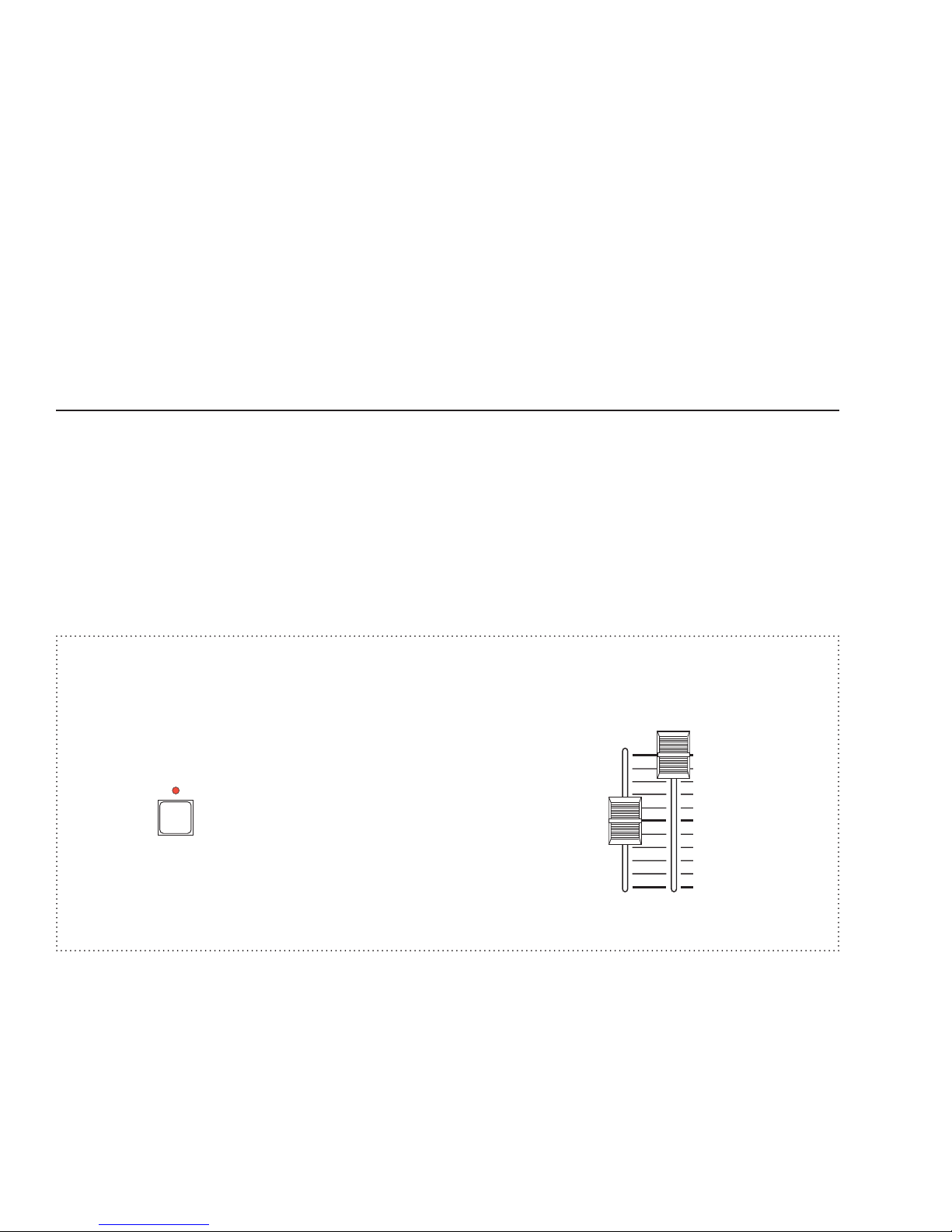
The chaser section will run any chase by pressing the CHASE SELECT button followed by selecting a chase number
using the Submaster Bump buttons. Each Submaster Bump button corresponds to a chase number.
Once selected, the chase will immediately begin with the first step at the chase rate represented by the current
setting of the Chase Rate control. The Chase Level slide control must be up for the chase to be active. The chase
will fade in at the selected master fade rate as indicated on the LCDs main menu
.
Only one chase can run in the chaser section at one time. When a new chase is selected, the previous one will
cancel and fade out at the set fade rate.
Example: Select Chase number one (Chase #1 must be already recorded).
1. Chase level to maximum.
2. Chase rate to midway.
3. Rotate encoder until fade rate = 0:00.0
4. Press
button.
5. Press Submaster 1 Bump button.
6. Chase 1 is running (If not, see Recording Chases).
Chases running in the chaser may be modified in that the direction and attack may be changed by pressing the
DIRECTION and ATTACK buttons. Chase rate may be set by using the Chase Rate slide control or by tapping the
TAP SYNC
Page 16 of 32
button at the desired rate.
Leviton MC 7500 Series Memory Lighting Controllers
Page 17
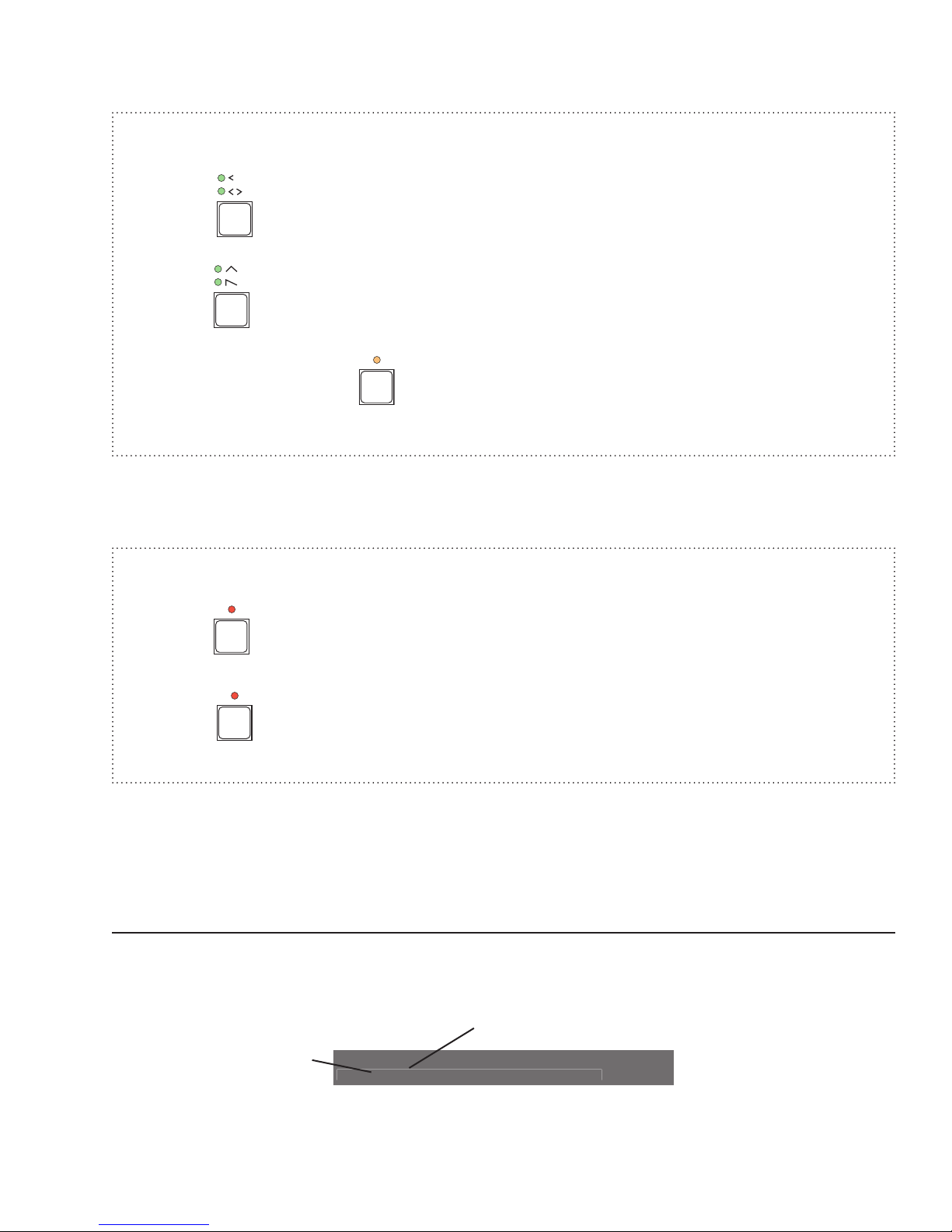
Example: Modify Chase number one (Chase #1 must be running as above example).
DIRECTION
ATTACK
TAP
SYNC
CHASE
SELECT
BLACKOUT
Stack Step Fade Page Setup
*<* 0:00.0 1
User Guide
1. Press
2. Press
3. Move Chase Rate or press
button to change direction.
button to change attack.
button to change rate.
To cancel the chase running in the chaser, press the CHASE SELECT followed by pressing the BLACKOUT button.
This will cause the chase to fade out and will not change the state of the Blackout mode.
Example: Cancel Chase number one (Chase #1 must be running as above example).
1. Press
button.
2. Press
button.
Chases may be recorded into Submasters allowing multiple chases to run at the same time by raising the appropriate
submasters or activating the Submaster Bump button. Chases running in submasters use the same rate as the
chaser section and the Chase Rate slide control and TAP SYNC button have the same effect.
Using Cue Stack
The Cue Stack feature allows combinations of scenes and chases already stored in memory to be arranged as
steps in a stack.
The LCD displays the stack information as follows:
Next stack step
Current live stack step
Leviton MC 7500 Series Memory Lighting Controllers
Page 17 of 32
Page 18

User Guide
Stack Step Fade Page Setup
*<1:1 0:0.00 1
GO
Clear Step Fade Page Setup
1:1<1:2 0:00.0 1
GO
Clear Step Fade Page Setup
1:2<1:3 0:00.0 1
An asterisk in the STEP field indicates that the selected stack is empty (i.e.. 12:* where there are no steps programmed
for this stack). An asterisk alone without a STACK:STEP field indicates that the stack has been cleared (i.e.. 1:8<*
where the next step is a cleared stack).
The Stack may be selected as a stack number from 1 to 16 by pressing the Stack function button of the LCD display.
Pressing the button will increment the stack number. Holding the button and turning the encoder will change the
number up or down.
The stack always executes steps in numerical order from the first or selected step, starting over when the last step is
reached. Using the Step function button of the LCDs main menu may directly access any step. Pressing the button will
increment the step number while holding the button and turning the encoder will change the number up and down.
Pressing the STACK FADE GO button will cause the current step to fade out and the next step to fade in at the
programmed fade rate.
Steps may be executed manually by moving the Stack Fade crossfader control up and down. Each time the control
reaches the end of movement, the step will be advanced.
The STACK function button indicated on the LCD will change to the CLEAR function button, once a stack has been
executed using the
a cleared stack, and pressing the
GO button or the Stack Fade crossfader. Pressing this button will cause the next step to become
GO button or moving the Stack Fade crossfader will cause a fadeout of the stack.
Further pressing of this button will cause a new stack to be selected.
Example: Select and execute Stack 1 (assuming Stack 1 been recorded).
1. Press Stack Function button until 1:1 is displayed as next stack (see above).
2. Press STACK FADE
3. Press STACK FADE
button (current now 1:1, next now 1:2).
button (current now 1:2, next now 1:3).
4. Etc.
Page 18 of 32
Leviton MC 7500 Series Memory Lighting Controllers
Page 19
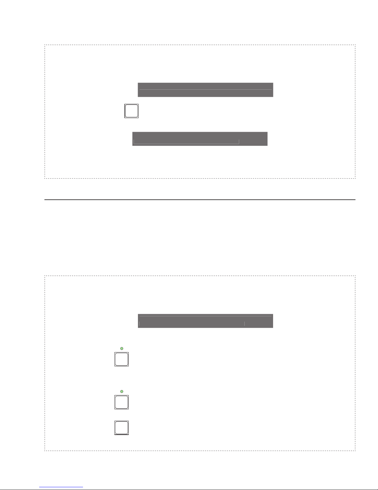
Example: Clear Stack 1 (assuming Stack 1 set as above example).
Stack Step Fade Page Setup
1:2<* 0:00.0 1
GO
Stack Step Fade Page Setup
*<* 0:00.0 1
Stack Step Fade Page Setup
*<* 0:02.0 1
GO
GO
CLEAR
1. Press Clear Function button (next stack shows *).
User Guide
2. Press STACK FADE
button (stack shows *<*).
Substitute moving the Stack Fade crossfader instead of pressing the Stack Fade GO button in the above
examples.
Snapshot
This feature allows a snapshot to be taken of the Scene A slide controls and sent to stage, fading at the master
fade rate.
Each press of the SNAPSHOT GO button will cause a new snapshot to fade to stage.
Pressing the SNAPSHOT CLEAR button causes the snapshot scene to fade out.
In the Wide Mode (sngl scn) Scene B slide controls will represent the additional channels and will be sent to stage
as one complete snapshot with Scene A.
Example: Take Snapshot of scene A twice, then clear it.
1. Rotate encoder until fade rate = 0:02.0 (to show fading),
2. Set Scene A preset sliders to various levels.
3. Tap SNAPSHOT
button and note channels fading on channel level LEDs.
4. Set Scene A preset sliders to different levels.
5. Tap SNAPSHOT
6. Tap SNAPSHOT
button and note channels fading on channel level LEDs.
button and note channels fading out.
Leviton MC 7500 Series Memory Lighting Controllers
Page 19 of 32
Page 20

User Guide
Grand Master
The Grand Master (GM) slide control provides proportional level control over all controller functions to stage with the
exception of the Bump buttons.
For example, whenever the Master Slide control is at minimum, all stage outputs will be at zero except for any
resulting from a Bump button press. If the
controller settings except for any resulting from a Bump button. If the
100% of the controller settings.
Whenever the Grand Master is not at maximum, the LED below it will flash.
Master is at 50%, all stage outputs will be at only 50% of their current
Master is at full, all stage outputs will be at
Blackout
The BLACKOUT button is used to disable all outputs to stage with the exception of those resulting from a Bump
button. This provides for quick dousing of stage levels or for creating solo effects when used in conjunction with the
Bump buttons. Blackout is active whenever the BLACKOUT LED is lit red.
Page 20 of 32
Leviton MC 7500 Series Memory Lighting Controllers
Page 21

User Guide
RECORD
PROGRAMMING
General
To initiate programming, first tap the RECORD button. This will light the RECORD LED indicating that the program
mode is active. Then tap the function button to be programmed. All programming is stored in nonvolatile memory,
which retains information for at least 10 years, even when power is removed.
Memory Pages
Depending on how the memory is configured, there are 8 or 16 pages of memory. A page consists of lighting levels
for all available submasters. The number of pages depends on whether or not the memory is setup to record normal
channels or wide mode channels.
Pages are changed by pressing the LCD function button marked Page on the LCD main menu to advance the page,
or by pressing and holding this button while rotating the encoder wheel to change page number up or down. If the
page is changed while a submaster is above minimum or a Submaster Bump button is active, the scene from the
previous page will remain and the Submaster Bump LED will flash amber. The new scene from the new page will
load and the LED will stop flashing when the submaster is reduced to minimum or the bump button is deactivated.
Recording Submasters (memory scenes)
Submasters and Submaster Bump buttons provide access to memory scenes. Recording lighting levels from stage
into Submasters is easy. Press the
record. A memory of what was on stage (minus any levels from chases) will now be stored in that submaster on the
current page.
EXAMPLE: Program the Submaster 1 with channels 1 and 6 at full, and 7 and 8 at 50%
1. Lower all Scene A slide controls and Submasters to minimum.
2. Both A and B Crossfaders at maximum.
3. Raise Scene A slide controls 1 and 6 to maximum.
4. Raise Scene A slide controls 7 and 8 to 50%.
5. Tap the
6. Tap Submaster 1 bump button.
7. Lower all Scene A slide controls.
button. The RECORD LED should now be lit.
RECORD button followed by pressing the bump button of the Submaster to
(assumes controller in Submaster Mode (SUBS)).
8. Raise Submaster 1 to see scene recorded.
If the Submaster is recorded while the Submaster slider is above minimum, or a Submaster Bump button is active,
the previous memory scene will remain and the Submaster Bump LED will flash amber. The new scene will load and
the LED will stop flashing when the Submaster is reduced to minimum or the bump button is deactivated.
Leviton MC 7500 Series Memory Lighting Controllers
Page 21 of 32
Page 22

User Guide
EDIT
Tap a Memory button, Chase Select
or Stack Go to Edit
P: 1 1 2 3 4 5 6 7 8 Chs
S: 1 100 0 100 0 100 0 100 0 *
Previewing Submasters
Submasters memories may be previewed on the Channel Level LEDs without affecting anything on stage. Pressing
the PREVIEW button to activate the preview mode does this. The preview mode is active whenever the LED above
the PREVIEW button is lit. Now pressing any Submaster Bump button will cause the scene contained in the submaster
to display on the Channel Level LEDs and the percentages of each channel will be displayed on the LCD. The LCD
may be
panned to display other channels by using the encoder wheel. Pressing the PREVIEW button again will
deactivate the preview mode and the LEDs and LCD will return to normal.
Editing Submasters
Submasters may be edited live (on stage) or blind (not on stage). To enter the edit mode, press the EDIT button
followed by pressing a Submaster Bump button.
The current levels in the selected submaster memory will be displayed on the Channel Level LEDs and the LCD
display much like the Preview mode. If the Submaster memory being edited is active (submaster slider up or bump
button active), then the edit is considered live, else it is blind.
Levels contained in memory are changed when the Scene A sliders are moved to match the current level and can
then be set to a new level. The LCD will indicate the match point when the LCD
and indicates a changing level. Also, the Channel Level LEDs and the stage, if live, will indicate new levels once
the match has been made.
auto-pans to display the channel
The encoder wheel may be used to change levels precisely by moving the encoder wheel until the cursor on the
LCD display is on the channel level to be changed. Hold down the
CHANGE button while turning the encoder to
set the new level.
A chase may be added to the Submaster memory at this point if desired, by pressing the LCD function button marked
Chs on the LCD, to increment the chase number. The Chs button may be held down and the encoder may be used
to select a chase number. Chase numbers range from
controller has. To deactivate a chase, set the chase number to
* (no chase) to 1 to as many submasters that the particular
*. Chases may be added to empty submasters via
the edit mode for chase-only submasters.
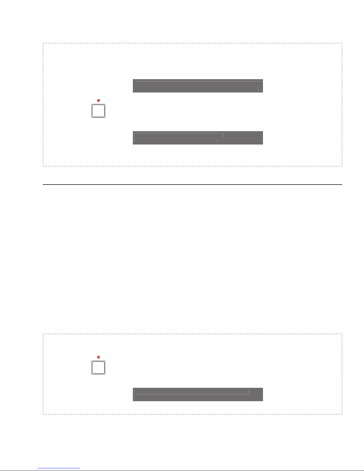
To save the changes, press the RECORD button. The LCD display will indicate the option of saving the stage levels
or just the modifications to memory. Once channels have had their levels changed while in the edit mode, they are
considered captured or modified. When modified edits (mods) are saved to memory, only the modified channel
levels are changed. All other levels in memory will remain the same.
Pressing the CANCEL button, or pressing the EDIT button again, will abort the edit process and discard any
changes.
Example: Edit Submaster 1.
1. Press the
button.
2. Press the Submaster Bump button 1.
Page 22 of 32
Leviton MC 7500 Series Memory Lighting Controllers
Page 23
User Guide
P: 1 1 2 3 4 5 6 7 8 Chs
S: 1 75 0 100 0 100 0 100 0 *
RECORD
Record edits from
Stage Mods
RECORD
Tap a Memory button, Chase Select
or Stack Go to Record
3. Using the Scene A slide controls, slowly move channel 1 slider from minimum to full until a match is made.
4. Then move the slider to a new level.
5. Press the
button and select the Mods function key on the LCD display.
6. The change to Submaster 1 is now recorded.
Recording Chases
Chases may be recorded in memory as a sequence of steps of different channel levels. When a chase is played
back, the channel levels of each step will appear on stage sequentially with the rate of step change set by the Chase
Rate control or the TAP SYNC button. At the end of the recorded sequence, the sequence repeats.
To record a chase, press the RECORD button followed by the CHASE SELECT button. The LCD will prompt for
the chase number to record. Use the Submaster Bump buttons, or the encoder wheel, to select the desired chase
number. Chase numbers available are from
of submasters). Press the Do Rec function button to start the chase recording procedure.
If the chase memory is not empty, then a warning message will appear on the display. Select Yes to erase the
selected chase memory and start recording.
Set the lighting levels for the first step with the Scene A slide controls, then press the Rec Step function button to
record the first step. The LCD will show the next step in sequence.
The attack for the entire chase may be recorded by selecting the
recording any step. The default direction for the entire chase may be recorded by selecting the
the DIRECTION button prior to recording any step.
1 to the maximum chases for the particular model (equal to the number
Attk function key or the ATTACK button prior to
Dir function key or
The number of steps that may be recorded depends on the memory configuration. To end the recording process, press
MAIN MENU button.
the
Example: Program a 4-step chase consisting of channels 1 - 4 into chase 2.
1. Press the
button. The RECORD LED should now be lit.
Leviton MC 7500 Series Memory Lighting Controllers
Page 23 of 32
Page 24

User Guide
CHASE
SELECT
Record Chase Do
1 Rec
Record Chase Do
2 Rec
Chase is not empty!
Clear? Yes N
Dir Attk Rec Chase: 2 Rec
-> [] Step: 1 Step
Dir Attk Rec Chase: 2 Rec
-> [] Step: 2 Step
Dir Attk Rec Chase: 2 Rec
-> [] Step: 3 Step
Dir Attk Rec Chase: 2 Rec
-> [] Step: 4 Step
Dir Attk Rec Chase: 2 Rec
-> [] Step: 5 Step
2. Press
Select button.
3. Select chase number 2 on the LCD and select Do Rec.
4. If chase is not empty, select Yes.
5. Move all Scene A slide controls to minimum.
6. Raise Scene A slider 1 to maximum.
7. Press Rec Step function button.
8. Lower Scene A slider 1 to minimum and 2 to maximum.
9. Press Rec Step function button.
10. Lower Scene A slider 2 to minimum and 3 to maximum.
11. Press Rec Step function button.
12. Lower Scene A slider 3 to minimum and 4 to maximum.
13. Press Rec Step function button.
14. Press the MAIN MENU button.
Page 24 of 32
Leviton MC 7500 Series Memory Lighting Controllers
Page 25

User Guide
If the Chase is active when programming is initiated, the Chase will halt during programming and resume with the new
programming when completed. If the Chase was not active, it will not be running when programming is complete.
Recording Cue Stacks
Cue Stacks are a collection of scenes and chases that are already programmed in the submaster memories. Each
step of a stack may consist of scenes from any page in memory. Precise fade times in tenths of seconds may be
programmed into each step, and each step may be manually played back using the
using the Stack fader, or a wait time may be set for automatic execution.
GO button, manually crossfaded
To record a stack, press the
stack number to record. Stack numbers available are from 1 to 16. Press the respective Submaster Bump button
or use the encoder wheel to select the desired stack number. Press the “Do Rec” function button to start the stack
recording procedure.
If the stack memory is not empty, then a warning message will appear on the display. Select Yes to erase the selected
chase memory and start recording.
Select the memory scene for the first step by selecting the desired Submaster Bump button. To temporarily change
the page, press the Page function button or hold this button down and turn the encoder wheel.
The selected scene will appear on the channel LEDs per the bump mode, and will appear on the stage if the GM
is at maximum. If the wrong scene was chosen, simply select another scene. The levels in a particular scene may
be edited later if desired. The sub function button may be used to change the scene number if you do not wish to
view the scene.
The Page Number for the Submasters will revert back to the original one once recording is completed.
Setting fade time for each step is done by holding the change button down and rotating the encoder. The fade time
appears in the LCD display.
The user has the option to skip right to recording the step if desired, or you can add a chase number and/or wait time
by pressing the
time. Select a chase number by pressing the “Chs” function button, or hold this button down and turn the encoder
wheel.
The Wait Time is used for automatic execution of the stack. This is the time before the next step of the stack
automatically advances and fades. A Wait Time of zero indicates normal manual execution using the Stack Fade
GO button or crossfader. Select a wait time by pressing the Wait function button or hold this button down and turn
the encoder wheel.
More function button. This will change the LCD screen and function keys to allow chase and wait
RECORD button followed by the Stack Fade GO button. The LCD will prompt for the
If you wish to enter a real, SMPTE, or MIDI time instead of wait time (for advanced users only), press the More
function button again to advance to the SMPTE LCD screen. Press and hold the first function button while turning
the encoder wheel to adjust the Hour (HH) and Minutes (MM) parameters. Press and hold the second function button
while turning the encoder wheel to adjust the Seconds (SS) and Frames (FF) parameters. Entering SMPTE time
overrides Wait Time and vice versa .
Record the step by pressing the LCD
time, you can record more steps by selecting scenes to record and following the above procedure again.
To finish recording the entire stack, press the MAIN MENU button or the RECORD button (not the LCD Rec button)
and the stack will be saved. The maximum number of steps that may be recorded is 255.
Leviton MC 7500 Series Memory Lighting Controllers
Rec function button. The step number will advance to the next step. At this
Page 25 of 32
Page 26

User Guide
MIDI
MIDI Show Control
Format:
<sys ex = F0H><real time = 7FH><dev ID><msc = 02><lighing = 01 ><command><data><end sys ex = F7H>
Receives:
Command:
1: Go - Starts current step of active stack or loads stack and step indicated in the data field and executes.
Data (optional):
nn ... nn Cue (step) number, ASCII encoded. 1 - 255 are the only valid numbers.
Any characters after a decimal point will be ignored.
00: Delimiter.
ll ... ll Cue list (Stack numbers), ASCII encoded. 1 - 16 are the only valid
numbers.
Any characters after a decimal point will be ignored.
Ex. Start Step 2 of Stack 4:
F0H 7FH <ID> 02 01 <01> <32H 00 34H> F7H
6: Set
Data: nn nn Control Number, 7-bit, LSB first
vv vv Control Value, 7-bit, LSB first
Control: 0 -31 = Fading Memories 1 - 32
Value: 0 - 255
Values above 255 ignored.
Ex. Memory 2 at full (255):
F0H 7FH <ID> 02 01 <06><01 00 7FH 01>F7H
Control: 32 - 63 = Memories Bumps 1 - 32
Value: 0 - 255
Values above 255 ignored.
Control: 1024 = Memory Page.
Value: 0 - 15
Values above 15 ignored.
Control: 512 - 631 = Channels 1 - 64
Value: 0 - 255
Values above 255 ignored.
Control: 1026 = Activate Chase
Value: 0 - 32, 0 = Chase off, 1 - 32 = Chase 1 - 32
Values above 32 ignored.
Control: 1027 = Chase Rate
Value: 150 - 16383, BPM = (1 / (0.0005 X Value)) X 60
Values below 150 ignored.
Page 26 of 32
Leviton MC 7500 Series Memory Lighting Controllers
Page 27

User Guide
Control: 1028 = Fade Rate
Value: 0 - 1200, Seconds = Value / 10
Note On
Format:
<note on = 9cH, c = MIDI chan><note num = 0 - 127><veloc = 1 - 127>
Receives:
Notes 0 - 63 map to channels 1 - 64.
Velocity field sets level of channel with 0 representing off and 127 representing full on.
Example: Channel 16 set to 50% with MIDI channel set to 3.
93H 15H 64H
MIDI Time Code / SMPTE
In addition to linking steps of a Stack together through Wait times to create an automated sequence, each step of a
Stack can be assigned a SMPTE time. The Stack will then keep itself in sync with the time code allowing the controller
to perfectly follow a SMPTE synchronized presentation. SMPTE Time Code is input into the controller via the MIDI
ports, therefore the code needs to be converted to MIDI Time Code. The code is broken down into hours, minutes,
seconds and frames. All 4 styles of SMPTE (24, 25, 30 drop and 30 non-drop frame) are recognized.
If time code is input into the controller with no Stack active, each stack, starting with the first, is scanned until one
is found that has time code programmed. The Stack is then automatically activated. This allows a presentation to
start itself without having to load the Stack first. If a Stack is loaded, it will sync with the time code regardless of
whether it is the first Stack to have time code programmed in it. The time code will be displayed above the Fade Time
whenever the main menu is active, verifying that the code is being received and indicating what the current time is.
If the time code is removed or stopped, the Stack will stop at the current step, unless the Real Time Clock feature
is active, in which case the internal time keeping mechanism will keep the Stack running. If the external time code
is again applied, it will take over from the internal time base.
Leviton MC 7500 Series Memory Lighting Controllers
Page 27 of 32
Page 28

User Guide
TROUBLESHOOTING
Channel Level LEDs do not respond.
Ch a s e f u nct i o ns do not w o rk .
Lights on stage do not operate even
though Channel Level LEDs do.
Ch annel and/ or Sub master sli de
controls have no effect on channel
levels.
Stage lights are ON, but will not
respond or respond erratically.
Unit will not record wide mode channels
17-32 (25-48) [33-64].
RECORD button inoperative.
Corrupt parameters error message on
power up.
• Check to see if 1 x 32 (1 x 48) [1 x 64] mode is selected. Since
all channels cannot be viewed, the LEDs are disabled in this
mode.
• Make sure a rate has been established with the TAP SYNC button
or chase rate slider. The rate is indicated by the flashing LED
located directly above the TAP SYNC button.
• Make sure the chase level slider is not at minimum.
• Check that the Master Slide control is not set at minimum and
that the BLACKOUT LED is not ON.
• Make sure softpatch table is not cleared.
• Make sure that the X or Y Crossfader is not in its minimum
position.
• Make sure the dimmer packs are programmed correctly.
• Check for a bad control cable by replacing it.
• The dimmer pack may be defective.
• Check memory size setting in SETUP menu.
• Locked. Check SETUP menu for console locks.
• Check all Setup parameters in SETUP menu before other
operations or programming.
Reset and Memory Clear
The following procedure causes the entire memory of the console to be cleared and factory default parameters to be
installed. All programming and softpatches will be lost. This procedure may be used to clear the console to a known
starting point prior to new programming or rental.
1. Turn power switch OFF.
2. Hold down the following buttons: Function 1, Function 2, Help, Change.
3. Turn power ON while holding buttons.
4. Release buttons after 10 seconds.
Memory will be cleared after a few moments. A default softpatch will be installed.
Page 28 of 32
Leviton MC 7500 Series Memory Lighting Controllers
Page 29

Console Specifications
Control Channels: 16/32 (24/48) [32/64].
Maximum Dimmers: 512.
Submasters 16 (24) [32]
Pages: 16 / 8.
Chases: 16 (24) [32) 400 steps total.
203 steps in Wide Mode.
Memory: Non-volatile EEPROM (approx. 10 year retention).
Dimmer Outputs: Leviton-NSI Micro-plex.
DMX512.
User Guide
SPECIFICATIONS
MIDI: In / Out / Thru
Input Power: 120 / 240 Volts AC, 1A.
Dimensions (L x W x H): 23” x 15” x 4” (29” x 15” x 4”) [35” x 15” x 4”].
Weight (approx.): 13 lbs. (15 lbs.) [16 lbs.]
Leviton MC 7500 Series Memory Lighting Controllers
Page 29 of 32
Page 30

User Guide
WARRANTY
LIMITED TWO YEAR WARRANTY AND EXCLUSIONS
Leviton warrants to the original consumer purchaser and not for the benefit of anyone else that this product
at the time of its sale by Leviton is free of defects in materials and workmanship under normal and proper
use for two years from the purchase date. Levitonʼs only obligation is to correct such defects by repair or
replacement, at its option, if within such two year period the product is returned prepaid, with proof of purchase
date, and a description of the problem to Leviton Manufacturing Co., Inc., Att: Service Department, 20497
SW Teton Ave., Tualatin, Oregon 97062. All products returned to Leviton-NSI must have factory authorization
for return prior to shipping. The purchaser is responsible for completing and mailing to Leviton, within 15 days
of purchase, the warranty registration card enclosed with each product. This warranty excludes and there is
disclaimed liability for labor for removal of this product or reinstallation. This warranty is void if this product is
installed improperly or in an improper environment, overloaded, misused, opened, abused, or altered in any
manner, or is not used under normal operating conditions or not in accordance with any labels or instructions.
There are no other or implied warranties of any kind, including merchantability and fitness for a particular
purpose, but if any implied warranty is required by the applicable jurisdiction, the duration of any such implied
warranty, including merchantability and fitness for a particular purpose, is limited to two years. Leviton is not
liable for incidental, indirect, special, or consequential damages, including without limitation, damage to, or
loss of use of, any equipment, lost sales or profits or delay or failure to perform this warranty obligation. The
remedies provided herein are the exclusive remedies under this warranty, whether based on contract, tort or
otherwise.
Page 30 of 32
Leviton MC 7500 Series Memory Lighting Controllers
Page 31

User Guide
Leviton MC 7500 Series Memory Lighting Controllers
Page 31 of 32
Page 32

User Guide
Leviton NSI Division Headquarters
20497 SW Teton Avenue, Tualatin, OR 97062
Customer Service Telephone: 800.736.6682
Customer Service Fax: 503.404.5594
Technical Services: 800.959.6004
Leviton Manufacturing Company, Incorporated
59-25 Little Neck Parkway, Little Neck, NY 11362-2591
Visit Levitonʼs websites at http://www.nsicorp.com & http://www.leviton.com
Copyright® 2003. Leviton Manufacturing Company, Inc. All Rights Reserved
Page 32 of 32
Specifications and pricing subject to change at any time.
Leviton MC 7500 Series Memory Lighting Controllers
PK-93382-10-00-0A
Page 33
User Guide
DOCUMENT
A
TION
LEVIT
ON INSTRUCTION SHEET/MANUAL
SPECIFICA
TIONS
EC
06/23/04
Helvetica
PK-93382-10-00-0A
Black
Final fold size:
Min. 24 lb., min. 90 brightness
Front/rear page gloss card stock
Pamphlet bind-booklet
Overall size:
8.5" X 11" (32 pages)
Paper size:
This page is NOT to be printed in the booklet
Leviton MC 7500 Series Memory Lighting Controllers
Page 33 of 32
 Loading...