

Page 1

Table of Contents
Table of Contents i
About The Encore® ix
About This Manual xiii
How to Use This Manual xiii
Text Conventions Used in this Manual xiii
About the User Guide xiv
About the Reference Section xiv
About the Appendices xv
ENCORE USER GUIDE 1
PART I: GETTING STARTED 1
CHAPTER 1: 3
Setting Up Your Console 3
Step 1: Unpacking 3
Step 2: Set Up 3
Step 3: Power Connections 4
Step 4: Control Connections 5
Step 5: Worklights 5
Step 6: Energizing the Console 5
Step 7: Operating the Console 6
PART II: Fundamentals of Operation 9
CHAPTER 2: 11
Basic Console Conventions 11
Terminology Definitions 11
Console Controls 12
Display Keys 15
Macro Keys 15
Hard Keys vs. Soft Keys 15
Command Line and Its Syntax 16
Command Line History 17
Captured Channels / Wheel Control 18
Grandmaster Fader 19
Blackout Switch 19
Console Memory 20
Record Disk / Load Disk 20
CHAPTER 3: 21
Displays 21
The Basic Display 21
Changing Displays 24
Default Items 24
Moving Within Displays / Position Keypad 25
Channel Formatting 26
The Stage Display (a live display) 28
The Preview Display (a blind display) 32
The Group Display (a blind display) 34
The Submaster Display (a blind display) 36
The Effect Display (a blind display) 40
The Cuesheet Display (a blind display) 42
The Tracksheet Display (a blind display) 44
The Playback Display (a live display) 46
The Patch Display (a blind display) 50
i
Software Version 3.05
Page 2

Colortran Encore Control Console
The Setup Display (a blind configuration display) 53
CHAPTER 4: 57
Console System Setup 57
Using the Setup Display 57
System Setup 58
Show Name 58
Number of Channels and Dimmers 59
Selecting Dimmer Protocol 60
Hand Held Remote 60
MIDI Interface 61
Reference By Name 61
Playback Fader Clearing Modes 61
CHAPTER 5: 63
Setting Up the Soft Patch 63
What is a Soft Patch? 63
Patch Displays 64
Patch: By Channel Display Mode 65
Patch: By Dimmer Display Mode 66
Other Patch Display Modes 66
Patching Channels to Dimmers 67
Unpatching Channels and Dimmers 68
Default Dimmer or Channel 68
Patch 1 To 1 69
Automated Channels 70
CHAPTER 6: 71
Setting Channel Levels 71
Two-Scene Preset Mode* 71
Channel Faders vs. Keypad in Multi-Scene Mode* 71
Crossfader Time* 73
Keypad Commands 74
Channel Lists 74
Captured Channels 75
Wheel Control 77
Proportional Control with the Wheel 78
Restoring Channel Levels (“Undo”) 78
Remainder Dim Command 79
CHAPTER 7: 81
Basic Submaster Operation 81
Submasters 81
Normal Submaster 82
Record Sub Command 82
Creating Subs Blind 83
Bump Buttons 84
Timed Submasters 86
Submaster Profiles 86
Selective Recording (Updating) of Subs 87
CHAPTER 8: 89
Creating and Recording Cues 89
Cues 89
Cue Time 90
Manual Cues 90
Software Version 3.05
ii
Page 3

Table of Contents
Cue Numbering 91
Record Cue Command 92
Selective Recording 93
Creating Cues Blind 93
CHAPTER 9: 95
Playing Back Cues 95
Cuesheet Display 95
Playback Display 95
GO Button 95
Stop/Reverse Key 96
Playback Faders 97
Playback Fader Boxes 98
Grandmaster Fader Box 98
Manual Fades 99
Take Control Buttons 99
Taking Manual Control of Timed Cues 99
Clearing Fades From the Playback Faders 100
Fade Loading Hierarchy / Simultaneous fades 101
Go To Cue Command 102
Go To Link and Go To Clean Up Commands 103
CHAPTER 10: 105
Editing Cues and Using Track Modes 105
What is the Preview Cue? 105
Cue Recording/Editing Modes (Track Modes) 106
Selecting the Track Mode 106
Tracking Levels 107
Hard and Soft Zeros 108
Creating Cues in Tracking Mode 108
Creating Cues in Cue Only Mode 108
Creating Cues in Clean Up Mode 109
Examples: Creating Cues Blind: Different Track Modes 109
The Clean Up Attribute (Clean Up Cues) 111
Editing Existing Cue Levels in Different Track Modes 113
Editing Existing Cue Levels in Tracking Mode 113
Editing Existing Cue Levels in Cue Only Mode 115
Editing Existing Cue Levels in Clean Up Mode 116
Changing Soft Levels to Hard Levels 116
Changing Hard Levels to Soft Levels (Restoring Tracking Levels) 116
Copying Cues in Different Track Modes 117
Deleting Cues in Different Track Modes 118
Moving (Renumbering) Cues in Different Track Modes 118
CHAPTER 11: 123
Names 123
Alpha Mode 123
Cue, Effect, Group, and Submaster Names 124
Show and Disk File Names 125
Reference By Name 126
CHAPTER 12: 129
Utilities, Warnings, Printing, and Default Settings 129
Help Utility 129
Flash Command Utility 130
Dimmer Check Utility 131
Software Version 3.05
iii
Page 4

Colortran Encore Control Console
Channel Check Utility 131
Cue Check Utility 132
Warnings and Error Messages 132
Printers 134
Printing 135
CHAPTER 13: 137
Memory 137
Console Memory vs. Floppy Disk Storage 137
Memory Test 137
Clearing Memory 138
Performing a “Hard Clear” 139
System Settings in Memory 139
Recording to a Floppy Disk 140
Retrieving from a Floppy Disk 141
Disk File Management Subdisplay 142
Selectively Retrieving From Floppy Disk 144
Upgrading Software 145
PART III: ADVANCED TOPICS 147
CHAPTER 14: 149
Groups 149
Recording Groups 149
Recalling Groups 150
Copying Groups 150
Renumbering Groups 151
Deleting Groups 152
CHAPTER 15: 153
Effects 153
What Are Effects? 153
The Effect Display 154
Creating Effects 154
Creating Effect Steps 154
Timing and Levels 155
Effect Patterns 156
Testing an Effect 157
Pile-On vs. Take Control Modes 158
Assigning Effects to Submasters and Cues 159
Editing Steps 159
Copying Steps 160
Renumbering Steps 161
Deleting Steps 161
Inserting Steps 162
Effect Utilities 162
Copying Effects 163
Renumbering Effects 163
Deleting Effects 164
CHAPTER 16: 165
Advanced Channel Lists 165
Complex Channel Lists 165
Absolute vs. Proportional Levels 166
Channel Lists Made with Ranges 167
CHAPTER 17: 169
Software Version 3.05
iv
Page 5

Table of Contents
Advanced Submaster Operation 169
Submaster Modes 169
Effect Submaster 169
Take Control Effects on Submasters 170
Inhibitive Submaster 170
Changing Modes 172
CHAPTER 18: 173
Profiles 173
Profile Editor Subdisplay 174
Defined Fade Points vs. Calculated Fade Points 175
Fix Range 175
Profile Utilities 176
CHAPTER 19: 179
Advanced Cues 179
Cue Follow 179
Delay Time 180
Split Fades 181
Cue Profiles 182
Cue Macros 183
Cue Names 183
Cue Links 184
Link Returns 184
Link Repetitions 185
Link Loops and Specifying Repetitions 187
Tracking Levels in Link Commands 189
Multipart Cues 190
Creating Multipart Cues 191
Viewing Multipart Cues 192
Editing Levels in Multipart Cues 192
Using Clean Up in Multipart Cues 193
Playback of Multipart Cues 193
Assigning Effects to Cues 194
CHAPTER 20: 195
Advanced Patching Options 195
Dimmer Profiles 195
Proportional Levels 195
Non-Dim Dimmers (Virtual Non-Dims) 196
Parking Dimmers 197
Viewing Parked Dimmers 199
Uses for Parked Dimmers 200
Automated Channels 201
CHAPTER 21: 203
Macros 203
Recording Macros 203
Macro Paging 205
Viewing Macros 206
CHAPTER 22: 207
Controlling Fade and Effect Rates with the Wheel 207
Changing Cue Fade Rates 208
Changing Submaster Effect Rates 208
Changing Cue Effect Rates 209
CHAPTER 23: 211
Software Version 3.05
v
Page 6

Colortran Encore Control Console
Load Key Operations 211
Load Key 211
Range Loading 212
Loading Cues to Submasters 213
Loading Groups to Submasters 213
Loading Effects to Submasters 214
Loading Cues to Playback Faders 214
CHAPTER 24: 217
Selective Recording 217
Selective Recording of “New” Items 217
Selective Overwriting of Pre-existing Items (Updating) 218
PART IV: APPENDICES 219
APPENDIX A: 1
Maintenance and Customer Service 1
Upgrading Software 1
Memory Test 2
Replacing AC Power Fuses 3
Replacing the RAM Backup Battery 3
Replacing the Output Protection Module 5
APPENDIX C: 1
Hand Held Remote 1
Protocol 1
Pinout Information 1
Functions 2
Hand Held Remote Keys and Their Functions 4
APPENDIX D: 1
MIDI Interface 1
Introduction to MIDI 1
Enabling MIDI 1
Using Standard MIDI Messages 3
Using MIDI Show Control Messages 6
Testing the MIDI Ports 8
APPENDIX E: 1
ColorNet™ Remote Video 1
About ColorNet™ 1
System Components 1
System Wiring 3
Functions 4
Remote Video Displays 5
Channel Formatting 6
APPENDIX F: 1
Encore Console Specifications 1
APPENDIX G: 1
Auxiliary Monitor (Dual Video Option) 1
Setting Up the Auxiliary Monitor 1
Functions 1
Auxiliary Monitor Displays 2
Channel Formatting 2
User Guide Index 3
Software Version 3.05
vi
Page 7

About The Encore®
Congratulations on the purchase of your new Encore lighting control console!
The Encore Series of lighting control consoles have been designed to be both simple and
intuitive to operate, yet sophisticated and powerful in their programming. You'll
discover that the Encore Series has a "multi-level user" operating approach: with a wide
variety of manual and programmed controls, running lights with the Encore can be as
basic or as comprehensive as your needs require. For example:
?? The Encore 24/48 and 48/96 models may be operated as either completely manual
2-Scene Preset
consoles, or as a fully programmed Memory consoles.
?? The first 48 or 96 channels on the Encore 24/48 and 48/96 models have dedicated
channel faders for
quick, live control.
?? Advanced cue parameters include:
- multiple parts - special cue timing parameters
- custom fade profiles - cue names
- cue effects - cue macros
?? Advanced cue sequencing features such as links, follows and subroutines.
?? Programming features for operating color scrollers and moving lights.
?? MIDI Interface for synchronization with other control devices.
?? Hand Held Remote optional remote control device gives you freedom.
?? Optional Auxiliary and Remote Monitors provide additional information where
you need it.
?? Operating System stored in Flash-ROM allows easy System Software upgrades
from floppy disk.
?? Selective Memory Loading from standard 3.5" High Density 1.44 MB floppy
disk.
?? Help Feature provides instant on-line answers to your questions.
?? Factory-installed or Field-upgradable options:
- 2nd local monitor (Dual Video Option)
- Remote Video support (ColorNet? Option)
- Expansion Option for 24/48 and 48/96 models (increased channel and cue capacity)
- XL/2 Upgrade Kit (for XL model only)
In addition, the monitor displays --your most important interface with the Encore-- have
been carefully laid out and color-coded, providing concise, at-a-glance feedback for all
Software Version 3.05
ix
Page 8
Colortran Encore Control Console
console functions. Programming is simplified by a command syntax that doesn't require
parameters to be entered in any specific sequence. And don't be afraid to take your show
on the road-- the Encore's rugged physical design will stand up to a wide variety of
abuse.
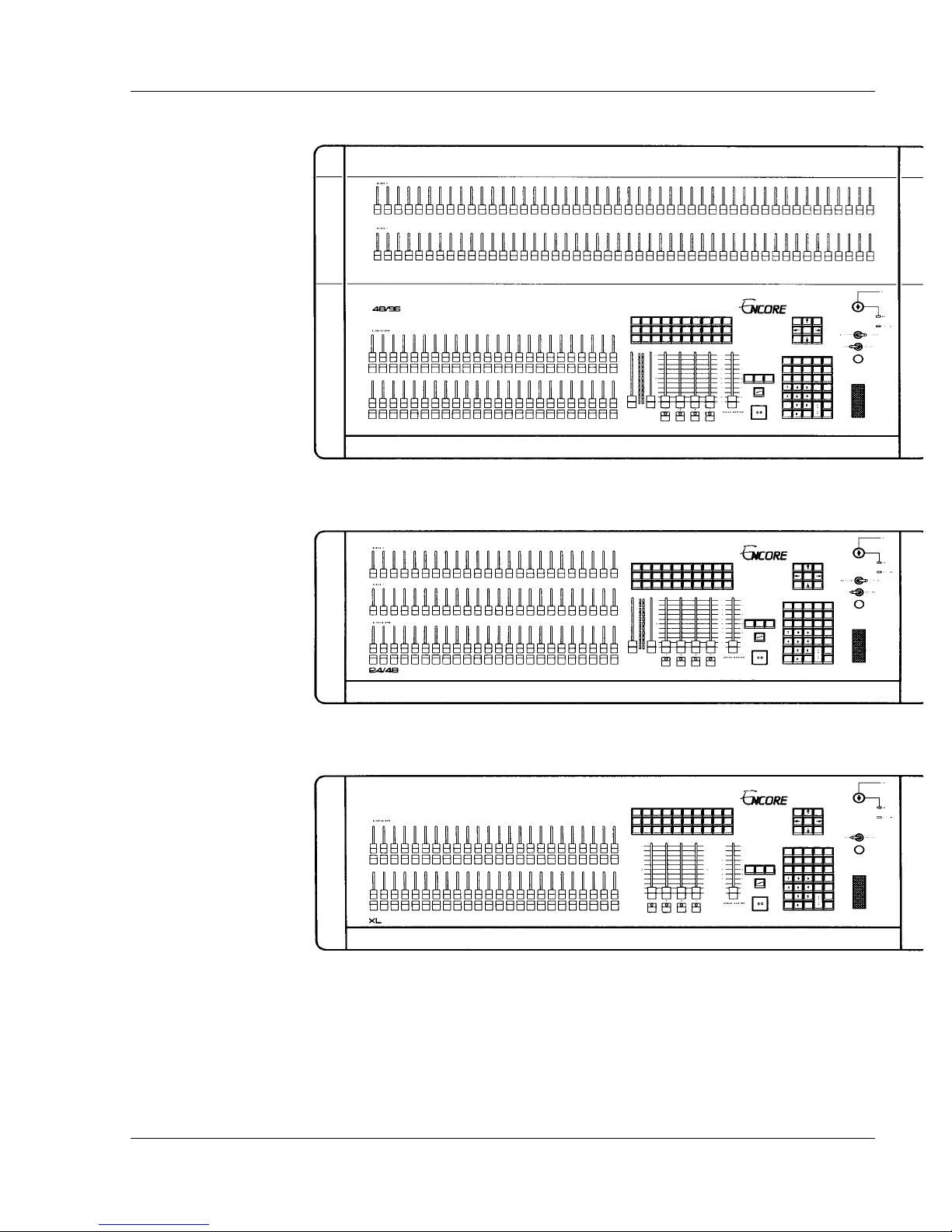
There are six different Encore models. The two main differences are:
?? The total number of channels, dimmers, submasters, cues, groups and effects
?? The ability to operate in a Two-Scene preset mode, in addition to the Multi-Scene
mode
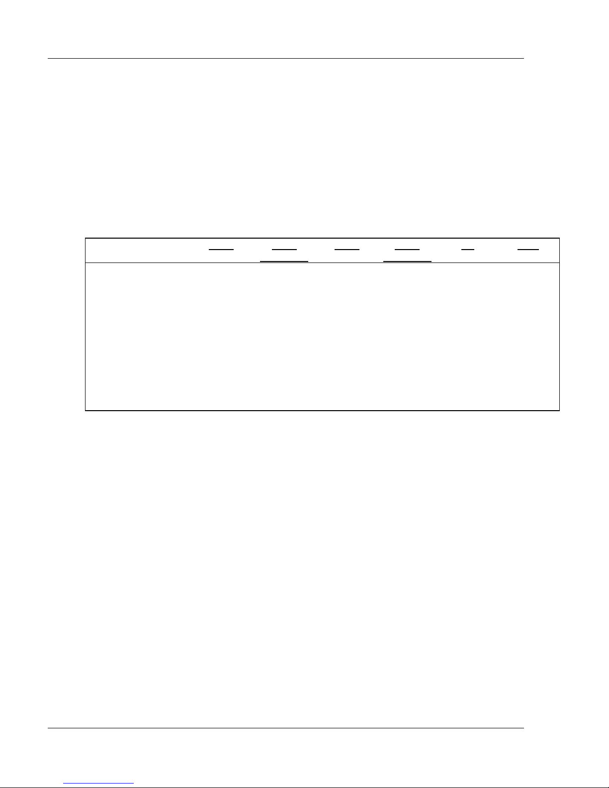
24/48 24/48
Channels
Two-scene mode 24 24 48 48 N/A N/A
Multi-Scene mode 144 512 144 512 512 1024
Dimmers
Expanded
48/96 48/96
Expanded
XL XL/2
512 512 512 512 512 1024
Submasters
Total Cues/Groups
(per show)
Groups
Effects
(per show)
Table I-1, Encore Models and Capacities
24 24 48 48 48 48
300 550 350 600 600 600
200 200 200 200 200 200
99 99 99 99 99 99
Software Version 3.05
x
Page 9
About The Encore
Encore Model
48/96
Encore Model 24/48
Encore Models XL and XL/2
Software Version 3.05
xi
Page 10

Page 11

About This Manual
How to Use This Manual
The Encore Manual is designed for both the first time user and the advanced
professional user. The User Guide is the first half of this manual. The User
Guide is designed so the novice user can start at the beginning, with the most
basic topics discussed first. It is arranged in chapters in order of increasing
complexity. The User Guide covers all topics in depth.
The Reference Section is the second half of this manual. The Reference
Section is a complete documentation of soft keys, hard keys, and operational
topics, arranged alphabetically. The Reference section is intended to provide
quick answers to specific questions without making you read through an entire
chapter.
Text Conventions Used in this Manual
In this manual, actual key names and keystroke entries appear in capital letters.
Soft keys appear inside parentheses: (SOFT KEY). Hard keys appear inside
brackets: [HARD KEY].
The key name and keystroke conventions are as follows:
?? Soft Keys appear as: (UPPERCASE
PARENTHESES)
(Soft keys are S1 - S10 on console.)
?? Hard Keys appear as: [UPPERCASE
BRACKETS]
(Hard keys are all other console keys.)
?? A number entry appears as: [#]
?? Single or multiple number lists appear as: [# list]
? EXAMPLE: The soft key, "Show Channel", appears as: (SHOW
CHANL)
? EXAMPLE: The hard key, "Group", appears as:
[GROUP]
? EXAMPLE: The number entry, "253", appears as: [253]
xiii
Software Version 3.05
Page 12

Colortran Encore Control Console
? NOTE: In the previous example, you enter the number 253 by
pressing the [2], the [5], and the [3] keys.
? EXAMPLE: "[# list]" is used as a generic example of a list of
numbers created using the Thru [>], And [+], and Minus [-] keys.
About the User Guide
The User Guide is the first half of this manual. The User Guide has four Parts:
PART I, GETTING STARTED
PART II, FUNDAMENTALS OF OPERATION
PART III, ADVANCED TOPICS
PART IV, APPENDICES
The User Guide is organized with comprehensive chapters that discuss various
topics in depth. The most basic topics start with Chapter 1. The following
chapters get progressively more advanced. Topics always provide a
description, and may also provide any or all of the following:
?? EXAMPLE: A sequence of keystrokes that executes a practical
example.
Software Version 3.05
BASIC RULE: A description of a basic rule that you should know.
?
Basic Rules usually apply to more areas of operation than the topic you are
reading.
? HINT: A good tip that will help you operate the console more
?
effectively.
?? NOTE: Important information about console operation specifics.
Notes usually point out exceptions to rules.
?ADVANCED TOPIC: A reference to a related advanced topic,
?
typically in a later chapter.
xiv
Page 13

About This Manual
About the Reference Section
The Reference Section is the second half of this manual. The Reference
Section is a complete alphabetic listing of soft keys, hard keys, and operational
topics. The Reference Section begins with keystroke symbols ([.], [-], [>], etc.).
The Reference Section is designed so the experienced user can answer specific
questions quickly.
A description of each console key is provided in the Reference Section. The
topic describes where the key is located, and how it functions. A keystroke
procedure that uses the key is also provided. Other keystroke combinations will
become apparent as you gain more experience with Encore commands. Related
topics are also listed at the end of each topic entry.
About the Appendices
The following appendices are included as part of this manual:
?? Appendix A: Maintenance and Customer Service
?? Appendix B: Soft Key Layout Chart
?? Appendix C: Hand Held Remote Operation Instructions
?? Appendix D: MIDI Interface
?? Appendix E: ColorNet™ Remote Video
?? Appendix F: Encore Console Specifications
?? Appendix G: Auxiliary Monitor
Software Version 3.05
xv
Page 14

Page 15

ENCORE
USER GUIDE
PART I:
GETTING STARTED
CHAPTER 1 Setting Up Your Console
Software Version 3.05
Page 16

Page 17

CHAPTER 1:
Setting Up
Your Console
Step 1: Unpacking
Carefully unpack your console from its carton. Underneath the console, you
will find:
?? This manual
?? A 7' AC power cable
?? One 3.5", 1.44MB floppy show storage disk
?? One 3.5", 1.44MB floppy disk containing the console operating program
?? One 3.5", 1.44MB floppy disk containing the Help file
?? 1 or 2 gooseneck Worklight fixtures (if the option was ordered)
In a separate shipping container, you will find the console monitor. Carefully
inspect all items for evidence of shipping damage. If any damage is noted, call
the shipping company for an inspection. It is recommended that you keep the
shipping containers in case you need to transport your console in the future.
Step 2: Set Up
Place your console on a sturdy horizontal surface with at least 6" (152mm) of
clearance behind the console for cables and for proper ventilation. The
environment should be dust-free with an ambient temperature of 40?F (4?C) to
90?F (32?C) and a relative humidity between 8% to 80% without condensation.
WARNING!! Do not run the console while it is in a road case, or
?
damage may occur.
Do not expose console to rain or moisture, or
damage may occur.
Place your monitor on a sturdy surface near the console in accordance with the
instructions provided by the monitor manufacturer.
Step 3: Power Connections
Power Supply Specifications: The console has an auto-ranging
power supply designed to operate on AC power at any nominal voltage between
Software Version 3.05
3
Page 18
Colortran Encore Control Console
Dimmer Control
Output (DMX)
100V and 240V, 50Hz or 60Hz. The power supply requires a maximum of 4A
(480 Watts). In the USA and Canada, it is intended that the console be
operated at 120V only, and a power cord with a NEMA/CSA 5-15P plug
(Edison, parallel blade type) is supplied for this purpose. In other countries
with different connector systems and/or operating voltages, you must use a
power cord with plug rated for at least 4A and at least the nominal operating
voltage of that country. The mating connector to the console is a female IEC
320, Sheet C13 connector rated at 10A, 250V.
Console Power Connection: First make sure the key switch is in the
OFF position, then plug the AC power cable into the console. Plug the other
end into an AC power source with a rating in compliance with the above
requirements, and with a computer grade ground. (A computer grade ground is
an insulated, isolated ground preferably connected to the point where the AC
power source is grounded in the building.)
Back Panel Power Outlets: On the back panel of the console are two
switched female IEC 320 style power outlet connectors for connecting the
monitor, or other peripheral devices. The connectors are rated voltage-wise
and frequency-wise at the same voltage and frequency being supplied to the
console via the console power supply cord, and collectively at 3A total for the
two switched outlets.
Monitor Power Connection: Your monitor is also typically an auto-
ranging unit, operating on AC power anywhere from 100V to 250V, 50Hz or
60Hz at a current of 1A maximum. The monitor is provided with a mating
"reverse" IEC 320 style plug. Refer to the instructions provided with the
monitor to find out whether the monitor is suitable for operation with the above
specified connectors. If so, plug the power cord of the monitor into one of the
console power connectors.
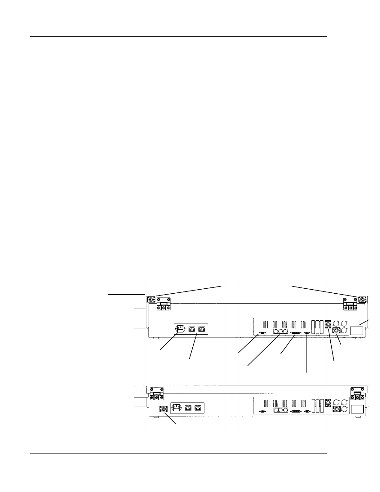
Model 48/96
Worklight Connectors
(optional)
Models 24/48, XL, & XL/2
Figure 1.1, Encore Back Panels
Software Version 3.05
AC Power
Convenience
Video
Outlets
In/Out/Thru
Worklight Connector (optional)
4
MIDI
Parallel
Printer
Hand Held Remote
Colortran Service Only
Page 19

Chapter 1: Setting Up Your Console
Step 4: Control Connections
A label on the back panel of the console identifies all control connections. (See
Figure 1.1.) They are all Class 2 low voltage circuits (extra-low voltage in
some parts of the world).
Monitor Connection: The monitor is supplied with a control cable
terminated in a high-density 15-pin "D" connector. Connect the monitor
control cable to the console connector marked VIDEO. The VIDEO connector
is a computer industry standard SVGA control connector. You can secure the
connector with a small, flat blade screwdriver, or in some cases, with built-in
hand-screws.
Dimmer Rack Connection: Since the purpose of the console is to
control dimmers, you must connect the console to the dimmer rack via the
DMX connector(s) on the back panel (standard 5 pin XLR type female
connectors). The DMX signals comply with the USITT DMX 512-1990
standard (except that pins 4 and 5 are not used for a second RS485 data
transmission channel; pin 4 is not connected, and pin 5 is use for an analog
over-temp signal). The DMX 1 connector contains data for dimmers 1 through
512, and the optional second connector, DMX 2, contains data for dimmers 513
through 1024. Connect Colortran dimmer pack control cables or control cables
previously wired to Colortran dimmer racks to the DMX console connectors.
Peripheral Devices: If desired, peripheral devices may be connected to
the console back panel connectors as follows:
?? Printer = Computer industry standard parallel
printer connector.
?? Hand Held Remote = Accepts Colortran Model No.7-2021
Hand Held Remote.
?? MIDI = Industry standard Musical Instrument
Digital Interface
?? Service Use Only = For Colortran service personnel only
?
Appendix C. For information on MIDI, see Appendix D.
Step 5: Worklights
Worklights are optional console accessories. The worklight plugs into the 3pin XLR style connector on the right rear of the console. The Encore model
48/96 is supplied with a second worklight that plugs into the connector on the
left rear of the console. The rotary control knob for the worklight intensity is
on the top panel just below the blackout switch.
ADVANCED TOPICS: For information on Hand Held Remote, see
Software Version 3.05
5
Page 20
Colortran Encore Control Console
Step 6: Energizing the Console
WARNING!! Do not consume food or beverages while operating
?
the console, because lethal voltages (120V or 220V) exist inside the console.
Spills may cause a hazardous condition, or may cause damage to the console.
CAUTION! When the console has been stored in a cold
?
environment (below 40ºF ), do not turn the power on until the console warms
up, or else damage to the console may occur. You should avoid situations that
could cause condensation to occur inside the console.
Turning on the Monitor: Once the console and monitor have come to
room temperature (about 25ºC or 75ºF) the console is ready to be turned on.
Refer to the instructions provided with the monitor and turn on its power
switch. If you plug the monitor into a convenience outlet on the rear of the
console, you can leave the monitor power switch turned on because the
convenience outlet on the console is a "switched" outlet (it turns off when the
console is turned off).
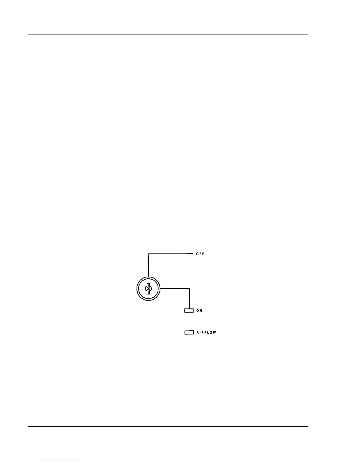
Figure 1.2, Power-On Key Switch
Turning on the Console: Next, turn on the console key switch located
on the upper right hand corner of the control panel. The ON indicator LED
should illuminate. Within about ten seconds, the monitor should warm up and
show one of the console displays. Refer to the instructions provided with the
monitor to adjust its display. You may remove the key from the Key Switch
while the switch is in either position.
Software Version 3.05
6
Page 21

Chapter 1: Setting Up Your Console
Step 7: Operating the Console
Use this manual when you have questions about how to operate the console.
The User Guide Part II covers Fundamentals of Operation. The User Guide
Part III covers Advanced Topics. The User Guide Appendices cover special
topics in depth such as Encore options and specifications. The Reference
Section in the back of this manual contains a comprehensive alphabetic listing
of all hard keys, soft keys, and related topics. If you are not able to find the
answer in the User Guide or the Reference Section of this manual, call
Colortran Field Service. Please have the following information available when
you call:
?? Console model number, configuration number (if any), and serial
number as found on the labels on
the back panel of the console.
?? Console software version number as shown at the top of the Setup
display.
?? Any accessories or peripherals attached to your system.
?? Dimmer types that the console is operating.
The Colortran Field Service number is (800) 959-6004.
Software Version 3.05
7
Page 22

Page 23

ENCORE
USER GUIDE
PART II:
Fundamentals of
Operation
CHAPTER 2 Basic Console Conventions
CHAPTER 3 Displays
CHAPTER 4 Console System Setup
CHAPTER 5 Setting Up the Soft Patch
CHAPTER 6 Setting Channel Levels
CHAPTER 7 Basic Submaster Operation
CHAPTER 8 Creating and Recording Cues
CHAPTER 9 Playing Back Cues
CHAPTER 10 Editing Cues and Using Track Modes
CHAPTER 11 Names
CHAPTER 12 Utilities, Warnings, Printing, and Default Settings
Software Version 3.05
Page 24

Page 25

CHAPTER 2:
Basic Console Conv entions
Terminology Definitions
Lighting Console: A lighting console is a tool that creates lighting
patterns and effects, and records them so they may be reproduced later. Simply
put, the console controls what is seen on stage.
Show: A show is the largest unit of memory. Only one show is ever active
in the console at any given time. Shows can be stored on standard 3.5"
computer floppy disks as show files. These files can be retrieved from floppy
disks and loaded back into the console's active memory in whole or in part.
Shows are composed of cues, effects, groups, submasters, macros, profiles, the
patch table assignment, and the system setup.
Cue: Cues are recorded lighting changes or "looks" that can be reproduced
with specific timing. Cues are numbered and are usually "played back" in a
numbered sequential order. Cues can be recorded and edited.
Effect: Effects are continuous repeating patterns of lighting changes that can
be assigned to cues or played back independently. The rate and pattern of an
effect can be recorded and edited.
Channels: Cues, effects, groups, and submasters are composed of selected
control channels, simply referred to as channels. Channels are used for setting
lights to various intensity levels.
Level: A level refers to the intensity of any lighting instrument that is
controlled by a given channel. A level is indicated by a percentage of the
maximum output of a given channel, from zero (00) to Full (FL). The level
number indicates the percentage of the maximum output, i.e. a channel level of
55 indicates that instruments controlled by the channel are at 55% of their
maximum intensity.
Assignment of Channels to Dimmers: Channels are assigned to
control specific dimmers. Dimmers are the actual hardware devices that feed
electricity into the circuits that feed your lighting instruments. In some venues,
different circuits can be physically plugged into specific dimmer outputs,
providing what is called a "hard patch". With the Encore console, you can
assign any channel to control one or more dimmers through what is called a
"soft patch".
?
ADVANCED TOPICS: See Chapter 5, Setting Up The Soft Patch.
Software Version 3.05
Page 26

Colortran Encore Control Console
Dimmer Control Channel: A dimmer control channel is a logical
address in the dimmer control signal transmitted from the console. This
dimmer control signal is a digital signal that contains information about many
dimmer control channels. The dimmer control signal can be used to control
actual dimmers or it can control other devices, such as automated fixtures and
color scrollers. Since the majority of applications have actual dimmers
controlled by the dimmer control signal, we use the term "dimmer" to refer to a
dimmer control channel. When you see the word "dimmer" in this manual, or
on the display monitor, it really means dimmer control channel.
Dimmer Protocols: There are different types of dimmer control signals,
also known as dimmer protocols. The current standard for dimmer protocols is
known as DMX-512, and was developed by the United States Institute for
Theater Technology. The Encore console can transmit DMX-512, or CMX
(Colortran protocol), each of which contains up to 512 dimmer control
channels, which may address either actual dimmers or other automated devices.
Software Version 3.05
12
Page 27
Chapter 2: Basic Console Conventions
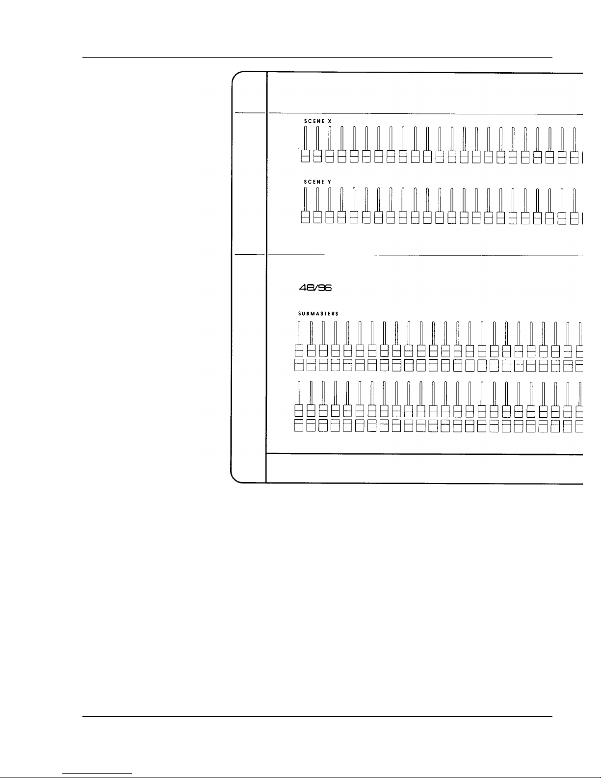
Figure 2.1.a, Encore Console Controls, Left Side
Console Controls
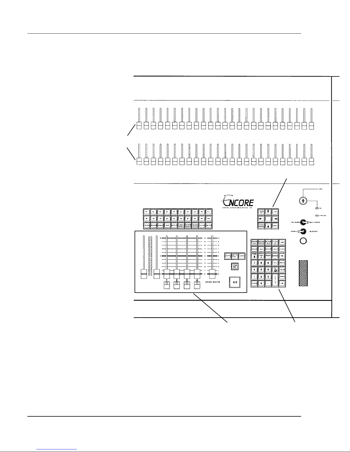
(See Figure 2.1). The main functional groups of console controls are as
follows:
?? Submaster faders and their Bump buttons are on the left side.
Software Version 3.05
13
Page 28
Colortran Encore Control Console
Position
Keypad
Channel
Sliders
Data Entry Keypad
Playback Controls
"Soft" Keys
Macro Keys
Display Keys
Figure 2.1.b, Encore Console Controls, Right Side
?? Playback controls are in the lower center.
?? Display keys are in the upper center.
?? Position Keypad is in the upper right.
?? Data Entry Keypad is in the lower right.
Software Version 3.05
14
Page 29
Chapter 2: Basic Console Conventions
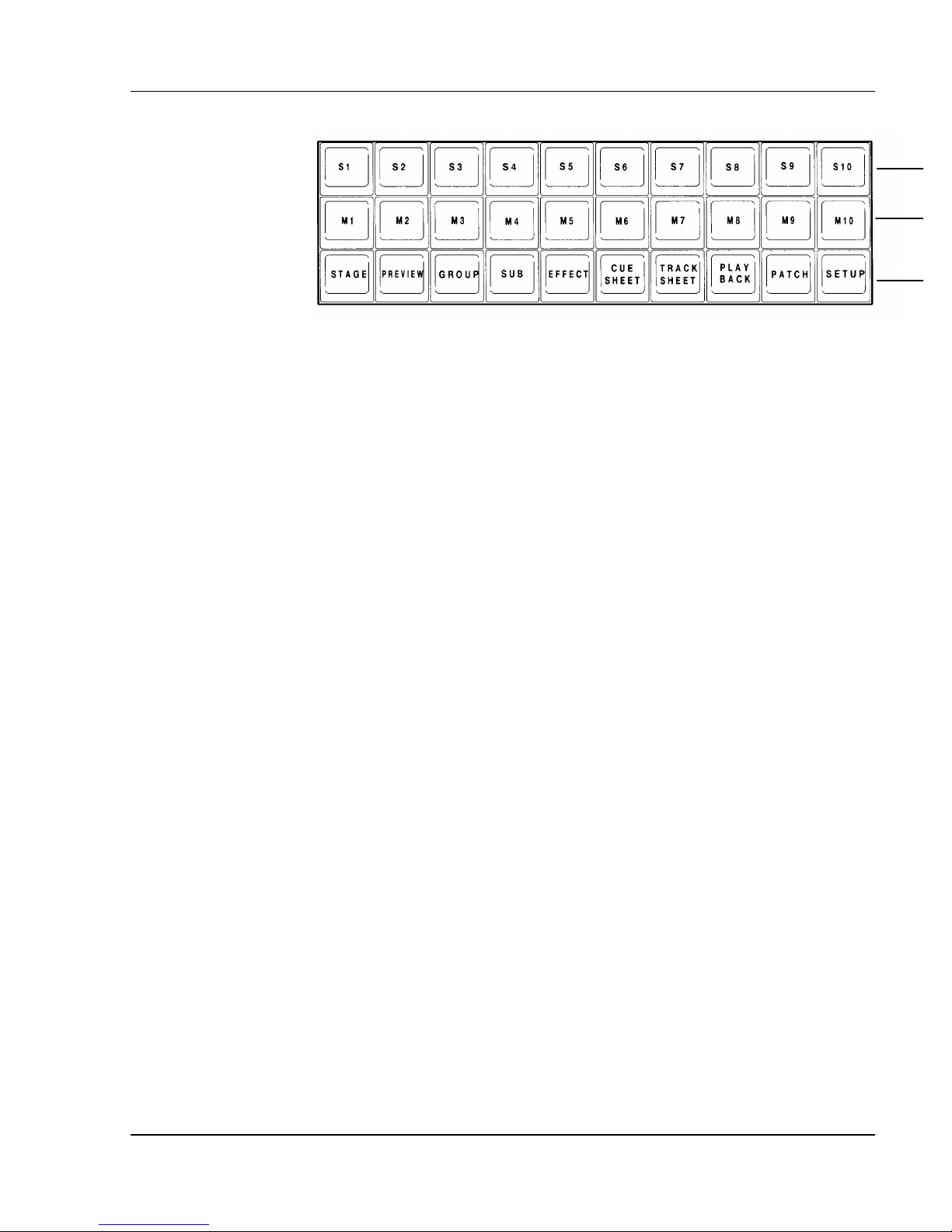
Soft Keys
Figure 2.2, Soft, Macro, and Display Keys
Display Keys
The Display keys are used to select the display on the video monitor screen.
There is one row of Display keys. Each key is labeled with the name of the
display that appears when the key is pressed. There are more than 10 displays
available, but some of these are actually subdisplays of the 10 main displays.
Subdisplays are available through soft keys in the main displays.
ADVANCED TOPIC: For a complete listing of all displays, see
?
Chapter 3, Displays.
Macro Keys
The Macro keys are a time and effort-saving feature. They are used to play
back a series of recorded keystrokes. Each Macro key can record a sequence of
up to 128 keystrokes. The sequence can then be re-executed at a later time by
simply pressing the assigned Macro key.
?
ADVANCED TOPIC: See Chapter 21, Macros.
Hard Keys vs. Soft Keys
Hard Keys: Hard keys are the keys on the console that always have the
same function. Hard keys are labeled with the name of the function that the
key performs.
Soft Keys: Soft keys are ten keys on the console that do not always have
the same function. (See Figure 2.2.) The soft key functions are different for
Software Version 3.05
15
Page 30
Colortran Encore Control Console
each display; their functions depend upon the display you are currently working
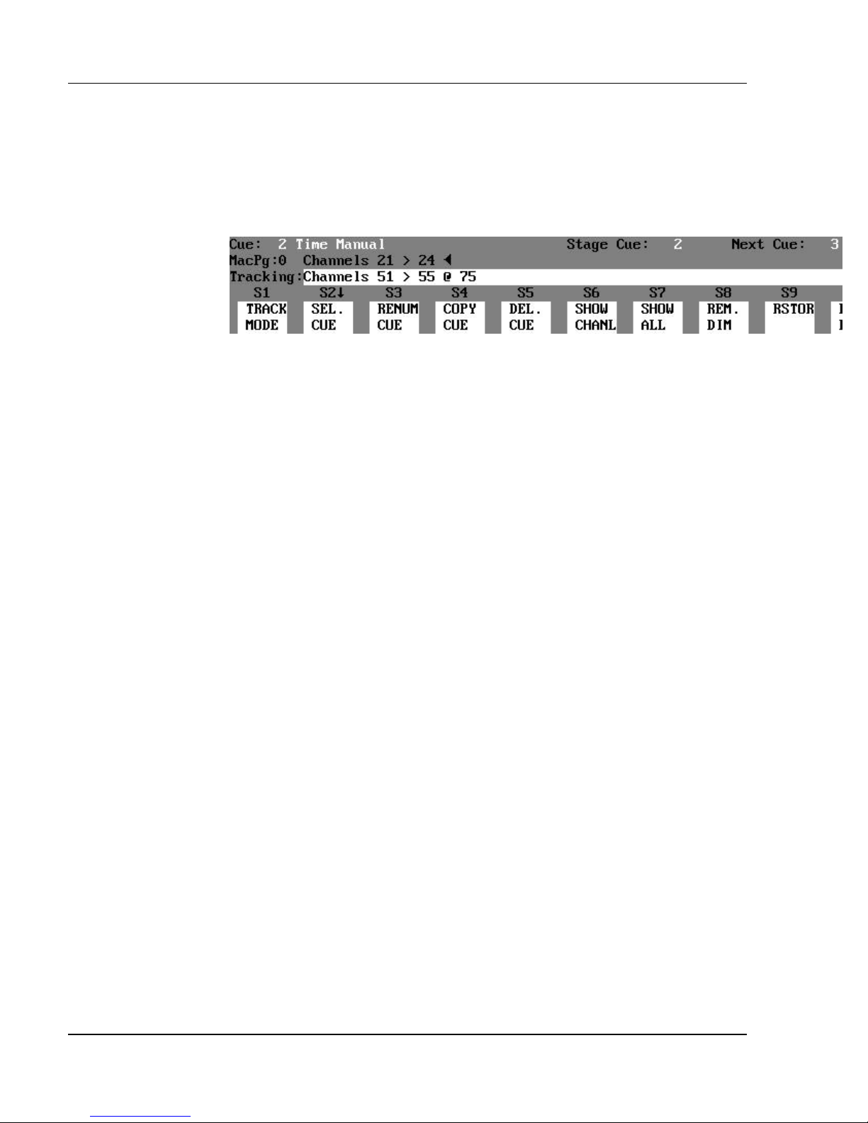
in. At the bottom of the screen (in all displays except Playback), there is a row
of ten squares that represent the ten soft keys for the current display. (See
Figure 2.3.) Each of the ten squares is labeled with its soft key function name.
The ten squares are numbered S1 - S10, just like the ten soft keys on the
console.
Figure 2.3, Soft Keys and Command Line
Whenever you change displays, you will notice that some or all of the soft key
labels change function names. Sometimes the soft keys will change when you
press a hard key or a soft key. As you use your Encore console, you will find
that you have the right soft key available when you need it. The labels names
are designed to communicate the function of the soft key, without having to
refer to this manual. The main idea behind the soft keys is to provide you with
only the functions needed in a particular display, without cluttering the top
panel with too many keys.
? NOTE: In this manual, actual key names and keystroke entries
appear in all capital letters. Soft keys appear inside parentheses: (SOFT
KEY). Hard keys appear inside brackets: [HARD KEY].
? EXAMPLE: The Record Submaster hard key appears like this:
[RECORD SUB]
The Track Mode soft key appears like this: (TRACK MODE)
The Decimal Point hard key appears like this: [.]
The AND hard key appears like this: [+]
The THRU hard key appears like this: [>]
The MINUS hard key appears like this; [-]
The AT hard key appears like this: [@]
? NOTE: The [AND] key on your console may be labeled "AND &" on
the key itself. In the Command Line this keystroke always appears as "+".
Some soft keys appear with a "down arrow" pointer next to them (?). This
indicates that the soft keys will change to another level of functions when you
press this key. To return to the previous level of soft key functions, press the
[CLEAR] key or the display key of the current display.
Command Line and Its Syntax
Software Version 3.05
16
Page 31

Chapter 2: Basic Console Conventions
The commands you enter into the console appear in the Command Line. The
Command Line is visible near the bottom of the monitor screen, just above the
soft keys. (See Figure 2.3.) A command is entered by pressing a sequence of
different soft keys and hard keys. Every keystroke you make appears on the
Command Line, creating a "sentence" that becomes a command for the console.
Your command is then completed by pressing the [ENTER] key, at which time
the console executes the command.
? EXAMPLE: A command to set channel 7 at a level of 75 percent
is:
[7] [@] [75] [ENTER] (Command Line History
shows "Channel 7 @ 75")
?
is entered at the beginning of the Command Line, "Channel" is automatically
entered onto the Command Line. Use the At [@] key to signify a channel level
or patching assignment. The [@] key can be roughly translated as "at the
level of" or "patched to".
?
[ENTER] key, you can use the [CLEAR] key to erase keystrokes in the
Command Line. The keystroke immediately to the left of the cursor is erased
from the Command Line when the [CLEAR] key is pressed. You can also use
the Left and Right Arrow keys on the Position Keypad to move the cursor
around in the Command Line.
BASIC RULE: There is no channel key, therefore anytime a number
BASIC RULE: Before you execute a command by pressing the
Command Line History
After pressing the [ENTER] key in the Example above, you will notice that
your command "sentence" moves up one line on the display, and appears in
gray text. The entered command is now in the position on the screen called the
Command Line History. The Command Line History provides you with a copy
of the last command that was entered. You cannot manipulate the information
in the Command Line History; it just shows what command you last entered.
Software Version 3.05
17
Page 32
Colortran Encore Control Console
Grandmaster Fader
Wheel
Blackout Switch
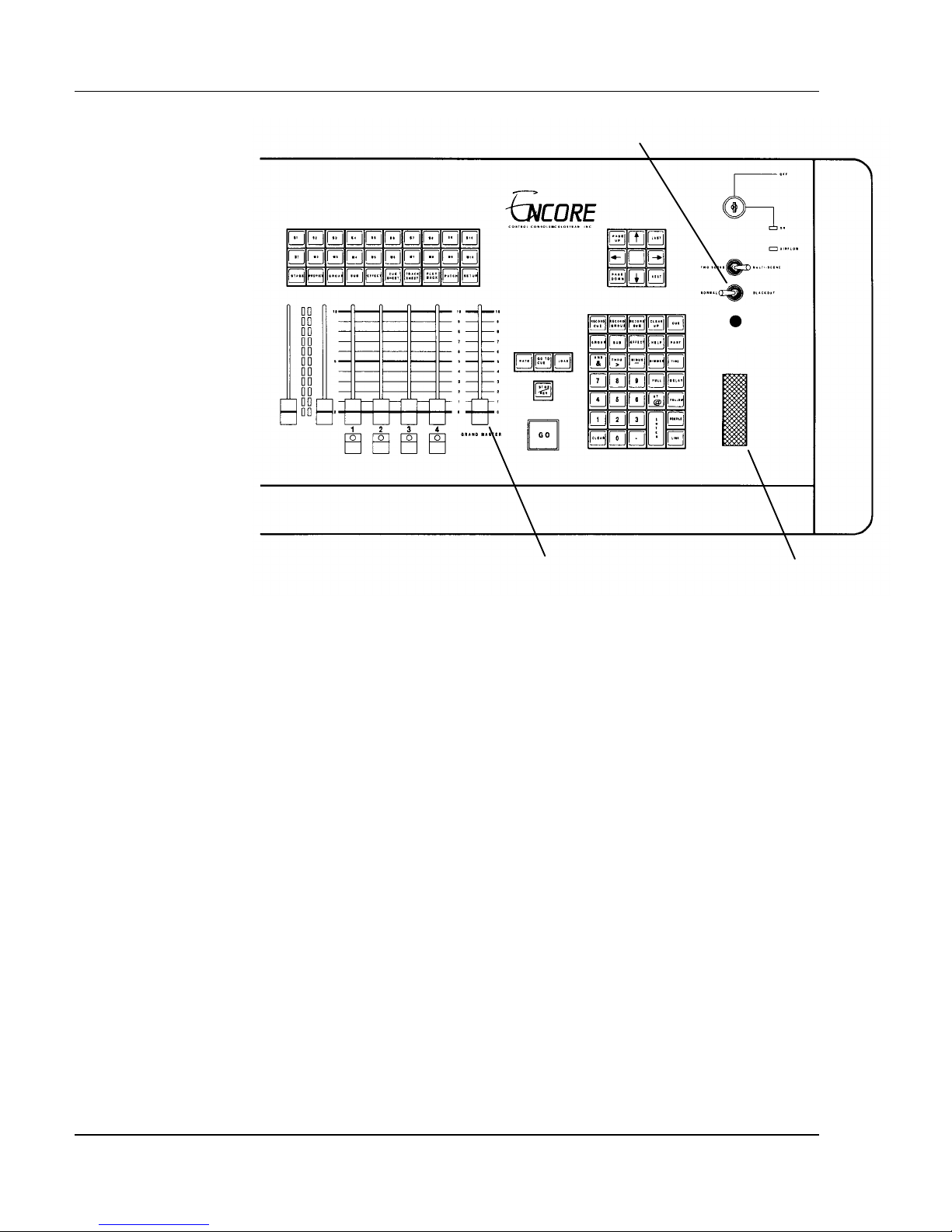
Figure 2.4, Console Wheel, Grandmaster, and Blackout Controls.
Captured Channels / Wheel Control
When you have set channel levels on the Command Line, the channels are
"captured", and are shown in cyan (aqua colored) reverse video. Captured
channels are under control of the wheel. Use the wheel to increase or decrease
the levels of captured channels in a continuous proportional manner. This
means that captured channels at different levels still maintain their proportions
with respect to each other. Captured channels remain "on the wheel" until you
select other channels or press the [CLEAR] key.
The captured channel levels can also be set by entering a new level value with
the Data Entry Keypad. In this case, there is no need to enter channel numbers
because the console automatically assigns the new levels to the captured
channels.
? EXAMPLE: To assign a level of 50% to channels 1 - 10, then change
to 80%:
1. [1] [>] [10] [@] [50] [ENTER]
2. [@] [80] [ENTER]
- or Move the wheel until the channels read 80%.
Software Version 3.05
18
Page 33

Chapter 2: Basic Console Conventions
ADVANCED TOPICS: See Chapter 6, Setting Channel Levels.
?
You can also use the wheel to control the rates of fades on the playback faders,
as well as the rates of effects on submasters or playback faders.
ADVANCED TOPICS: See Chapter 22, Controlling Fade And
?
Effect Rates With The Wheel.
Grandmaster Fader
You can use the Grandmaster fader to proportionally control the output of all
the channels. The slider "masters" all of the channel levels that are live on
stage. When the Grandmaster is restored to its original position, all channels
return to their previous levels.
? NOTE: Neither Parked dimmers nor Automated channels are
controlled by the Grandmaster.
ADVANCED TOPIC: See the Parking Dimmers topic in Chapter
?
20, Advanced Patching Options.
ADVANCED TOPICS: See the Automated Channels topic in
?
Chapter 5, Setting Up The Soft Patch, and in Chapter 20, Advanced Patching
Options.
Blackout Switch
You can use the Blackout switch to control the output to all the channels with
an on/off toggle function. Set the switch to BLACKOUT to immediately take
out all the lights on stage. Set the Blackout switch to NORMAL to return to
the previous levels. The Blackout switch function is the same as instantly
moving the Grandmaster slider between full and zero.
Software Version 3.05
19
Page 34

Colortran Encore Control Console
* WARNING *
Invalid stored values detected.
? NOTE: Neither Parked dimmers nor Automated channels are
affected by the Blackout switch.
HINT: Just to the right of the Playback Fader Boxes (in both the
?
Playback and the Stage displays), there is a level indicator box. It shows the
current level of the Grandmaster. Whenever the Grandmaster level drops
below full, the level indicated in this box flashes. If the Grandmaster reaches
zero, the level shows as the red flashing letters "B.O." (Blackout) to indicate a
blackout condition on the stage. The flashing red "B.O." also occurs when the
Blackout switch is in the Blackout position.
Console Memory
When you turn off your console, the console "remembers" the cues and all other
show information, so that when you turn the console back on, all the show
information from the previous session is still there. The show information is
stored in RAM (Random Access Memory) which remains active by an internal
backup battery when the console is turned off. If the console does not
remember the previous show, the battery may need to be replaced.
The console checks the show data stored in RAM each time power is turned on.
If the console detects invalid data, a warning message appears on the display
stating that the battery may need replacing. (See Figure 2.5.)
Record Disk / Load Disk
Software Version 3.05
RAM battery may need replacement.
- press CLEAR key -
Figure 2.5, Bad Battery Warning
ADVANCED TOPIC: To change the internal battery, see
?
Appendix A, Maintenance And Customer Service.
The current show data can be recorded from RAM onto a standard 3.5"
1.44MB High Density floppy disk for storage. You can then retrieve show data
from the floppy disk. The disk drive is located under the front edge of the
console.
20
Page 35

Chapter 2: Basic Console Conventions
ADVANCED TOPICS: To record and retrieve show data, see
?
Chapter 13, Memory.
Software Version 3.05
21
Page 36

Page 37
CHAPTER 3:
Displays
The Basic Display
There are two "live" displays where edits are seen live on stage as they are
made. The live displays are:
?? Stage display
?? Playback display
There are eight "blind" displays where edits are not seen live on stage. The
blind displays are:
?? Preview display
?? Group display
?? Submaster display
?? Effect display
?? Cuesheet display
?? Tracksheet display
?? Patch display
?? Setup display
Software Version 3.05
23
Page 38

Colortran Encore Control Console
Figure 3.1, Basic Display
Title Bar: The Title Bar is located across the top of the display. The Title
Bar contains the name of the display you are currently viewing. In the blind
displays, the Title Bar is a single cyan-colored horizontal line on the black
background. In the live displays, the Title Bar is solid cyan with a black
horizontal line running through it.
HINT: The different looks of the live and blind displays is meant to
?
help prevent the most common type of operator error, which occurs when an
operator thought they were editing live levels on stage, when they were
actually editing a cue in the Preview display.
Status Bar: The Status Bar is located below the main part of the display.
The Status Bar contains status information about what is being shown in the
current display. Each display contains different types of information in its
status bar, depending on what type of information is relevant to the current
display. The primary information fields shown are:
?? Stage Cue: shows the number of the current cue on stage.
?? Next Cue: shows the number of the cue that is executed by the next
press of the GO button
(automatically taking cue links and link returns into account).
Software Version 3.05
24
Page 39

Chapter 3: Displays
?? Mac Pg: shows the number of the macro page (0 - 9) currently being
accessed by the Macro Keys,
[M1] - [M10]. Each Macro page contains ten macros that are executed by their
respective macro keys.
?? ALPHA: flashes in green when Bump buttons are set to alphabet
character mode.
?? Dimmers Parked message only appears when there are dimmers
currently parked.
Command Line / Command Line History: Directly below the
Status Bar are the Command Line History and the Command Line. The
Command Line shows the command currently being entered. The Command
Line History shows the last command that was executed.
Track Mode: The current Track mode appears in the field at the far left of
the Command Line. One of the three Track modes will appear in the Track
mode field:
?? Tracking
?? Cue Only
?? Clean Up
Soft Key Labels: The Soft Key Labels, numbered S1 - S10, appear at
the bottom of the display, and change function according to the current display.
The functions of these soft keys are executed by pressing the respective console
keys labeled (S1) - (S10).
Some of the soft keys reveal another level of soft keys. These keys are indicated
by a “down pointer” character (?) next to their label. To return to the top level
of soft keys in any display, press the display key for the current display (this
also clears the Command Line).
? EXAMPLE: In the Effect display, pressing the (PATRN) soft key
reveals the next level of soft keys under it that assign effect patterns. Pressing
the [EFFECT] display hard key returns to the first level of Effect display soft
keys, and clears the Command Line.
?
previous level of soft keys.
HINT: If you press the [CLEAR] key you will also return to the
Software Version 3.05
25
Page 40

Colortran Encore Control Console
Changing Displays
To change to a different display, press one of the ten display keys on the
console. The hard display keys are listed below:
?? [STAGE] ?? [CUESHEET]
?? [PREVIEW] ?? [TRACKSHEET]
?? [GROUP] ?? [PLAYBACK]
?? [SUBMASTER] ?? [PATCH]
?? [EFFECT] ?? [SETUP]
The following subdisplay soft keys are available in the Patch display:
?? (PROFL DISP.) = Profile Editor subdisplay (also found in
the Setup display)
?? (NONDM DISP.) = Non-Dim Dimmers subdisplay
?? (PARK DISP.) = Parked Dimmers subdisplay
Macro contents are displayed by pressing the (VIEW MACRO) soft key in the
Setup display.
ADVANCED TOPICS: See Chapter 21, Macros.
?
Default Items
In many displays, one (or more) of the items listed is shown in reverse video.
Items shown in reverse video are the default items in the list. This means that
if you enter a command without specifying the item to act upon, the console
will automatically insert the default item(s) into the Command Line.
? EXAMPLE: In the Patch: By Channel display, assume channel 1
is shown in reverse video (it is the "current" channel). To patch channel 1 to
dimmer 50:
[@] [50] [ENTER]
Software Version 3.05
26
Page 41
Moving Within Displays / Position
Keypad
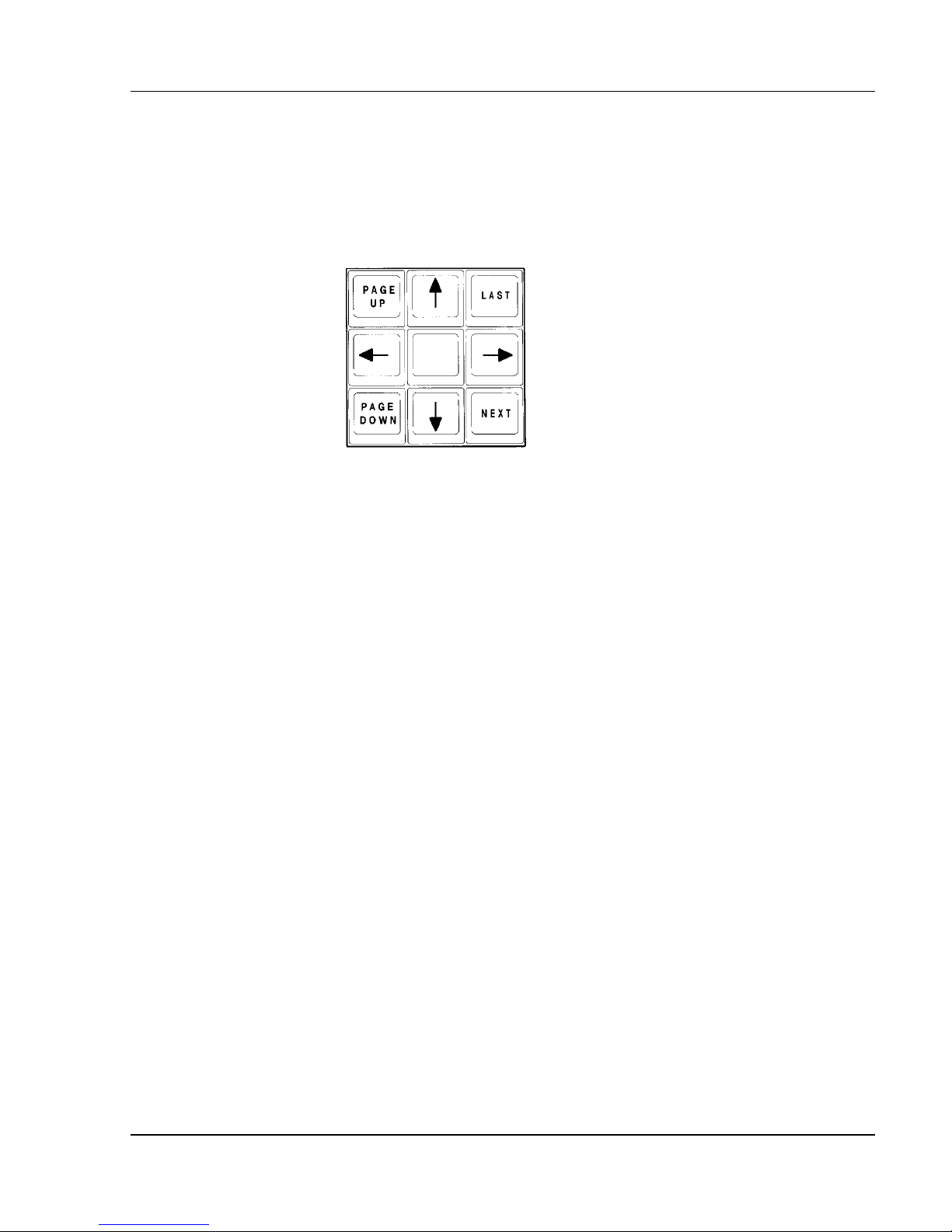
To move within a display, or to change the contents of the display, use the
Position Keypad. (See Figure 3.2.)
Chapter 3: Displays
Figure 3.2, Position Keypad
The [LAST] and [NEXT] keys generally change the display to select the next
or last item as the "current" item, such as the Effect or Submaster number that
is displayed.
The Up and Down arrow keys generally scroll (move) the contents of the
display vertically one line at a time. They move the current default selection in
the Effect display only.
The Left and Right arrow keys move the Tracksheet display left or right 12
channels at a time to reveal other channels for viewing.
The [PAGE UP] and [PAGE DOWN] keys show the next or previous page of
information.
Software Version 3.05
27
Page 42
Colortran Encore Control Console
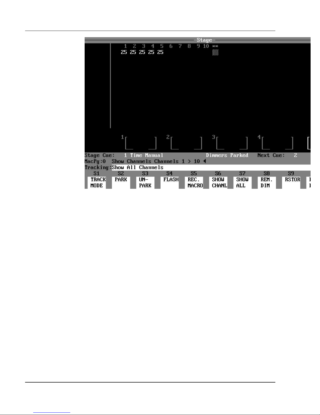
Figure 3.3, Channel Formatting
Channel Formatting
You can use the Show Channel (SHOW CHANL and Show All (SHOW ALL)
soft keys to format the display of channels. The total number of channels is
specified in the Setup display, or is determined by assigning the Two-Scene
mode or Multi-Scene mode (for the Encore 24/48 and 48/96 models). When
the (SHOW CHANL) soft key is pressed, the display is limited to show a subset
of all possible channels, and the characters "**" appear in the display
indicating that channels are not being shown. If a channel that is not shown
has an active level, a block of "dots" is shown below the "**".
? EXAMPLE: To set up the display to only show channels 1 - 10:
(SHOW CHANL) [1] [>] [10] [ENTER]
? EXAMPLE: To set up the display to show all active (non-zero)
channels:
(SHOW CHANL) [ENTER] (Do not specify a channel
list.)
Software Version 3.05
28
Page 43

Chapter 3: Displays
? NOTE: In the previous example, if no channels are currently
captured, then all active channels are displayed. If any channels are captured,
only they are shown.
? EXAMPLE: To show all channels, or all pages of channels:
(SHOW ALL) [ENTER]
The (SHOW CHANL) and (SHOW ALL) soft keys are available in the
following five "channel" displays:
?? Preview
?? Stage
?? Submaster
?? Group
?? Tracksheet
The Show Channel and Show All commands are global - the channels selected
for display are the same for all five channel displays. The Patch and Effect
displays are not affected by limiting the number of channels displayed. Any
printouts are also limited to the channels that are shown in the displays at the
time of the printing command.
BASIC RULE: Display formatting is temporary and does not affect
?
memory, or console output. However, display formatting does affect printouts
of show information.
Software Version 3.05
29
Page 44
Colortran Encore Control Console
The Stage Display (a live display)
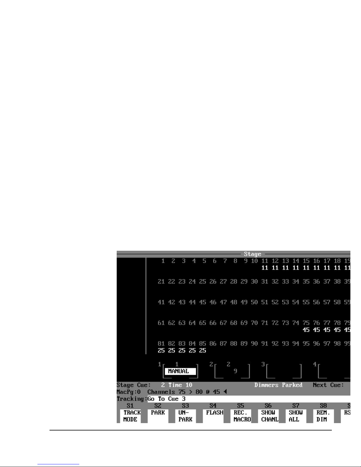
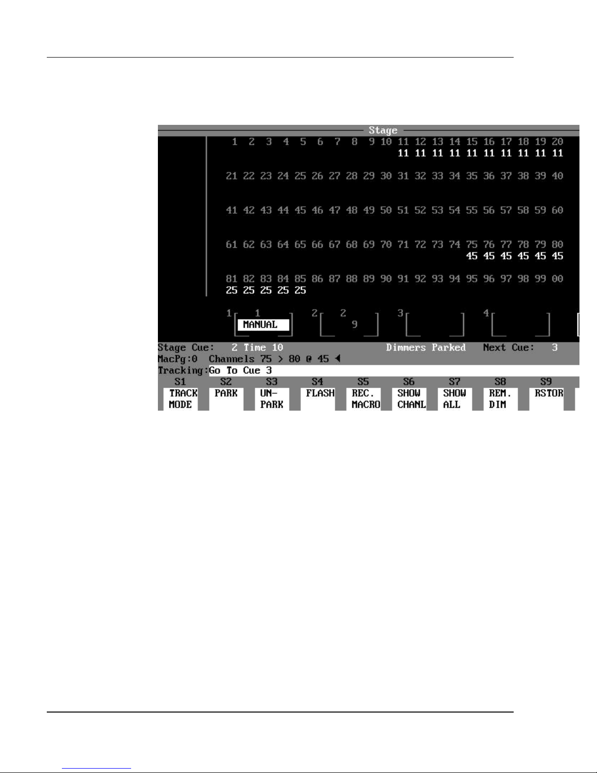
Figure 3.4 , Stage Display
Purpose of the Stage Display: The Stage display is a
representation of the current lighting levels being output live on stage to the
dimmer rack. Changes made to the levels directly affect the lights on stage, so
you can see what the changes look like. Changes to light levels are monitored
and updated instantly on the Stage display as the changes are made. A Record
command takes a "snapshot" of all channel levels that appear in the Stage
display. The Stage display also indicates the status of any running or fading
effects, and fading cues.
Software Version 3.05
30
Page 45

Chapter 3: Displays
Live Channels “on Stage”: In the main area of the display are the
channel numbers and their levels as seen “live on stage”. Paging with the
Position Keypad while in the Stage display affects only this area of the display.
The channel numbers are located in rows across the screen, and appear in
different colors as follows:
?? cyan = Normal channels
?? magenta = Automated channels
The level number of each channel is located below its respective channel
number. The lack of a level number indicates a level of zero. The levels appear
in different colors according to the code described below:
?? red = Higher level in current cue than last executed
cue.
?? blue = Lower level in current cue than last executed cue
?? white = Same level as last executed cue and not tracking.
?? gray = Tracking same level as last executed cue.
- or - = Channel fader controls the level directly.
- or - = Channel control was released from keypad or
wheel control.
?? yellow = Effect controls the channel.
?? green = Submaster controls the channel.
?? cyan block = Wheel controls the channel level directly (level
shown in white in an aqua block).
? NOTE: The only live levels that do not appear in the Stage display
are levels from dimmers that have been Parked. These Parked dimmers can be
viewed in the Patch: Parked Dimmers subdisplay.
ADVANCED TOPIC: See the Parked Dimmers topic in Chapter 20,
?
Advanced Patching Options.
Software Version 3.05
31
Page 46
Colortran Encore Control Console
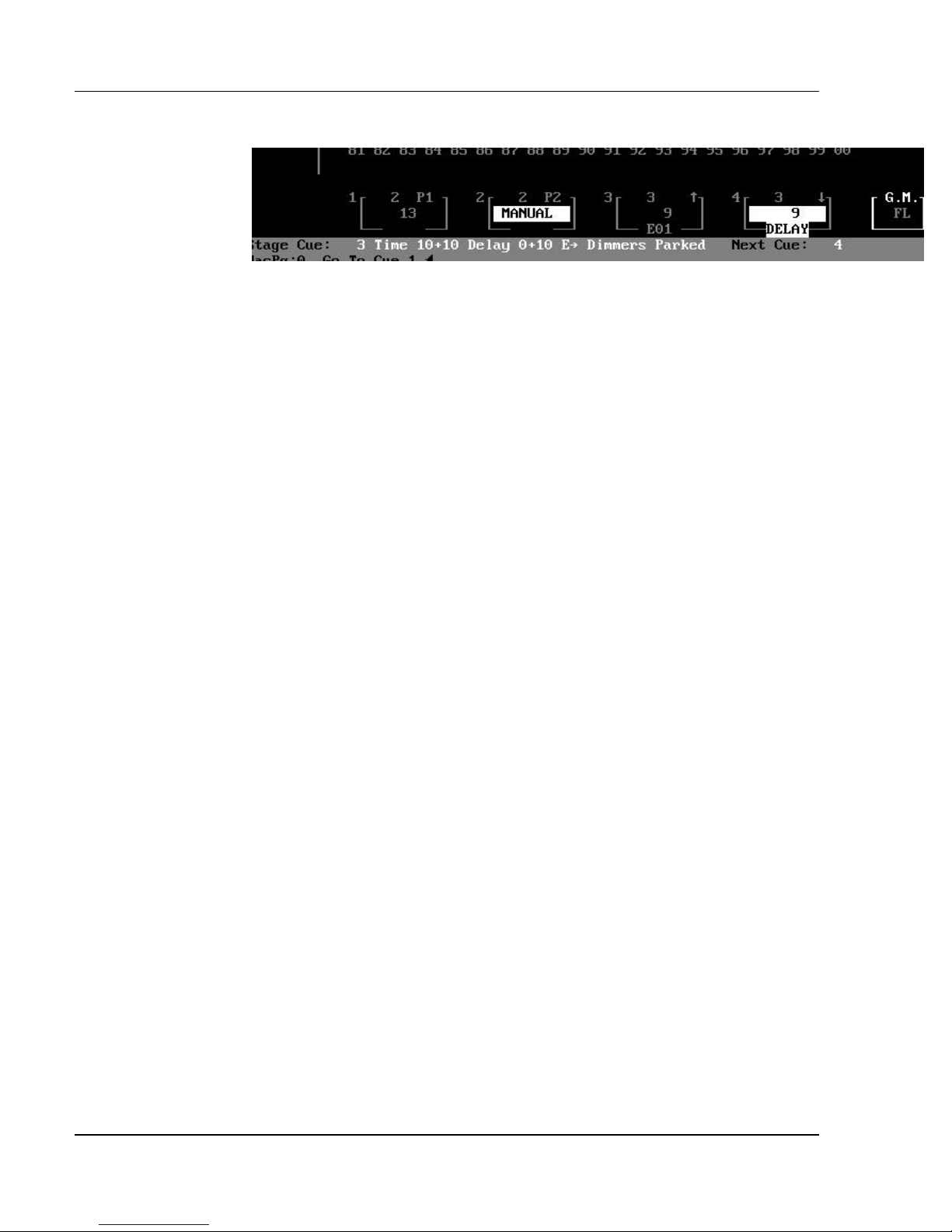
Figure 3.5, Playback Fader Boxes
Playback Fader Boxes: The four Playback Fader Boxes numbered 1 -
4 are located above the Status Bar on the Stage display screen. The Playback
Fader Boxes indicate the current status of any cues actively fading, or any
running cue effects. When a cue is executed by pressing the GO button or
using the [GO TO CUE] key, it is automatically loaded onto the lowest
available Playback Fader.
The Playback Fader Boxes contain the following information:
?? Cue number (the number on the top line of the box).
?? Cue Part number represented by the letter “P” before a number.
?? "?" indicates the up fade of a split fade cue.
?? "?" indicates the down fade of a split fade cue.
?? Fade time remaining is shown on the middle line of the box
- or-
"MANUAL" appears in reverse video when the fade is manually
controlled.
?? Delay time of the fade on the playback fader. ("DELAY" appears in
reverse video when the fade is
in the process of counting down its delay time.)
?? Effect number of the fade on the playback fader
?? "?" next to the effect number indicates a fade effect (no arrow indicates
a cue effect).
? NOTE: For manual cues, the word "MANUAL" starts to blink when
you move the fader handle from the zero position.
Software Version 3.05
32
Page 47

Chapter 3: Displays
Grandmaster Fader Box: To the right of the playback fader
information is the Grandmaster Fader Box. It indicates the level of the
Grandmaster, anywhere from 100% (FL=Full Level) to 0% (B.O.=Black Out).
The Blackout switch will also cause this indicator to read "B.O.". The
Grandmaster level blinks anytime it is set below Full.
Status Bar: Below the four Playback and the Grandmaster Fader Boxes is
the Status Bar. The Status Bar contains the following fields for information:
?? Stage Cue: shows the number of the current cue on stage.
?? Next Cue: shows the next cue number to be executed when the GO
button is pressed.
?? Mac Pg: shows the number of the macro page (0 - 9) currently being
accessed.
?? Dimmers Parked message only shows when there are dimmers
currently parked.
Command Line / Command Line History: Directly below the
Status Bar are the Command Line History and the Command Line. The
Command Line shows the command currently being entered. The Command
Line History shows the last command executed.
Track Mode: The current Track mode (Tracking, Cue Only or Clean Up)
is shown at the far left of the Command Line.
Soft Key Labels: The Soft Key Labels are located directly below the
Command Line. The Soft Key Labels describe the function of each soft key.
The function commands are executed by pressing one of the soft keys, (S1) (S10), on the console. The functions of the soft keys change for each display.
Software Version 3.05
33
Page 48
Colortran Encore Control Console
The Preview Display (a blind display)
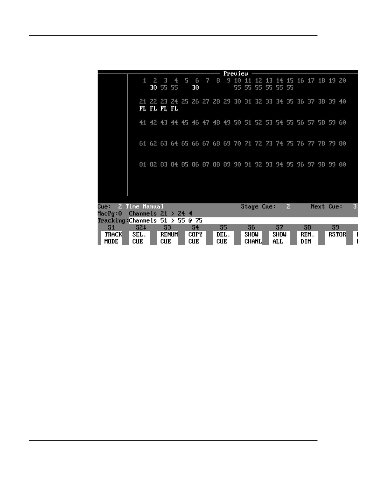
Figure 3.6, Preview Display
Purpose of the Preview Display: The Preview display shows the
recorded channel levels of a cue. Cues may be created and edited in the
Preview display. This is referred to as working in the "blind," because none of
the channel levels shown in this display can be seen as light output on the stage
while in the Preview display. Any edits to channel levels or cue attributes are
automatically recorded as they are entered (the Record Cue command is not
necessary to create or edit cues in the Preview display).
Contents of the Preview Display: The Preview display shows the
channel levels of any recorded cue. The upper part of the display shows
channels and their respective levels. The channel numbers are located above
the levels, and appear in the following colors:
?? cyan = Normal channels
?? magenta = Automated channels
Software Version 3.05
34
Page 49

Chapter 3: Displays
The numbers below each channel number is the level of that channel in the cue
being previewed. The levels are shown in different colors according to the code
described below:
?? red = Higher level than the previous cue
?? blue = Lower level than the previous cue
?? white = Non-tracking (or "hard" level), same level as last
cue
?? gray = Tracking (or "soft" level), same level as last cue
Status Bar: The Status Bar is located below the main channel and level
information area. The Status Bar contains the following fields for information:
?? Cue: shows the current preview cue being viewed and edited.
?? Stage Cue: shows the last cue executed on stage.
?? Next Cue: shows the next cue number to be executed when the GO
button is pressed.
?? Mac Pg: shows the number of the macro page (0 - 9) currently being
accessed.
Command Line / Command Line History: Directly below the
Status Bar are the Command Line History and the Command Line. The
Command Line displays the command currently being entered. The Command
Line History shows the last command executed.
Track Mode: The current Track mode (Cue Only, Tracking or Clean Up)
is shown at the far left of the Command Line.
Soft Key Labels: The Soft Key Labels are located directly below the
Command Line. The Soft Key Labels describe the function of each soft key.
The function commands are executed by pressing one of the soft keys, (S1) (S10), on the console. The functions of the soft keys change for each display.
Software Version 3.05
35
Page 50
Colortran Encore Control Console
The Group Display (a blind display)
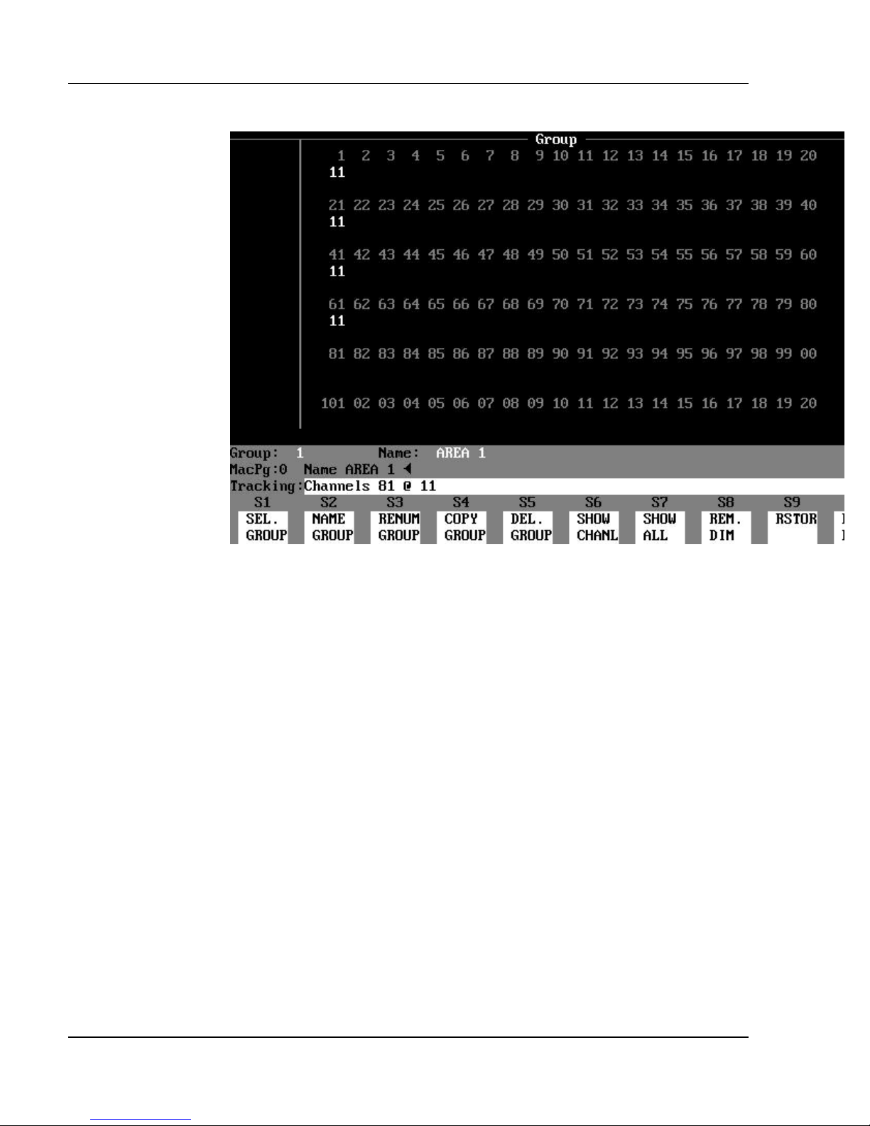
Figure 3.7, Group Display
Purpose of the Group Display: The Group display shows the
channel levels assigned to all existing groups. A group is a collection of
channels set at levels that may be created or edited in this display. A group is
just like a submaster but without the slider control. Groups are "building
blocks" used to create cues, effects or submasters. All edits to channel levels
are recorded as they are made (the Record Group command is not necessary to
create or edit groups while in the Group display).
Contents of the Group Display: The Group display shows the
channel levels of any recorded Group. The upper part of the display shows rows
of channels and their respective levels. The channel numbers, located above
the levels, appear in the following colors:
?? cyan = Normal channels
?? magenta = Automated channels
The numbers below each channel number is the level of each channel. If no
level is listed, the level is zero.
Software Version 3.05
36
Page 51

Chapter 3: Displays
Status Bar: The Status Bar is located below the channel and level
information area of the display. The Status Bar contains the following fields
for information:
?? Group: shows the current Group being viewed and edited.
?? Name: shows the name of the current group.
?? Mac Pg: shows the number of the macro page (0 - 9) currently being
accessed.
Track Mode: The current Track mode (Cue Only, Tracking or Clean Up)
is shown at the far left of the Command Line. The current Track mode has no
effect on groups.
Command Line / Command Line History: Directly below the
Status Bar are the Command Line History and the Command Line. The
Command Line displays the command currently being entered. The Command
Line History shows the last command executed.
Soft Key Labels: The Soft Key Labels are located directly below the
Command Line. The Soft Key Labels describe the function of each soft key.
The function commands are executed by pressing one of the soft keys, (S1) (S10), on the console. The functions of the soft keys change for each display.
Software Version 3.05
37
Page 52
Colortran Encore Control Console
The Submaster Display (a blind display)
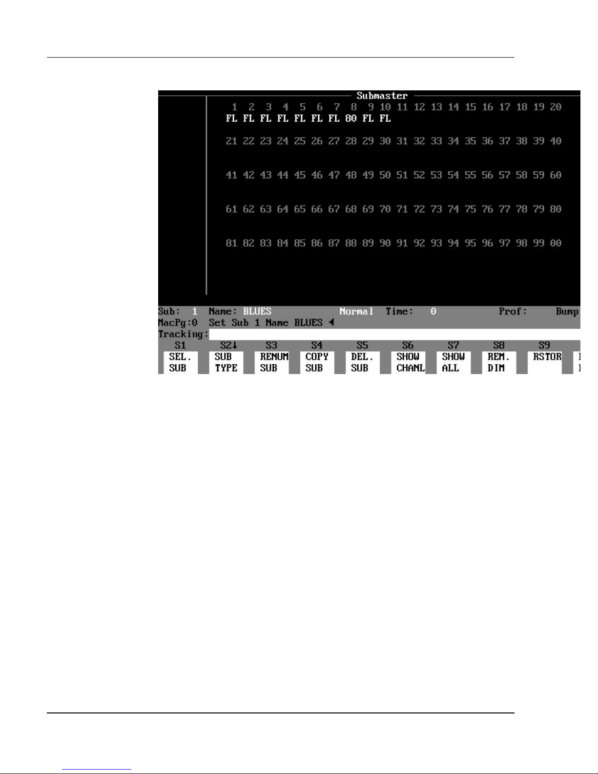
Figure 3.8, Normal Submaster Display
Purpose of the Submaster Display: The Submaster display
shows the channel levels assigned to each normal submaster, or shows
information defining inhibitive or effect submasters. Use the submaster display
to create and edit submasters. Any edits to channel levels or submaster
attributes in the Submaster display are recorded as they are entered (the Record
Sub command is not necessary to create or edit subs in the Submaster display).
There are three different types of submasters:
?? Normal submaster
?? Inhibitive submaster
?? Effect submaster
Contents of the Normal Submaster Display: The upper part
of the Normal Submaster display contains the channels and levels of a normal
submaster. (See Figure 3.8.) The channel numbers appear above their
respective levels. The channel numbers, located above the levels, appear in the
following colors:
?? cyan = Normal channels
?? magenta = Automated channels
Software Version 3.05
38
Page 53

Chapter 3: Displays
The numbers below each channel number is the level of each channel. If no
level is listed, the level is zero.
Normal Submaster Status Bar: The Status Bar indicates which
submaster is currently being viewed and edited. The Status Bar contains the
following information fields:
?? Sub: shows the number of current submaster.
?? Name: shows assigned name of current submaster, if any.
?? (Sub Type) shows "Normal" in gray letters as the current submaster
mode. (This information field,
located between the Name and Time fields, does not have a visible label.)
?? Time: shows the time assigned to the submaster Bump button.
?? Prof: shows the profile assigned to the submaster.
?? Bump: shows Bump button mode ("ON", "OFF", "SOLO", or "TOG").
?? Mac Pg: shows number of the macro page (0 - 9) currently being
accessed.
Command Line / Command Line History: Directly below the
Status Bar are the Command Line History and the Command Line. The
Command Line displays the command currently being entered. The Command
Line History shows the last command executed.
Soft Key Labels: The Soft Key Labels are located directly below the
Command Line. The Soft Key Labels describe the function of each soft key.
The function commands are executed by pressing one of the soft keys, (S1) (S10), on the console. The functions of the soft keys change for each display.
Software Version 3.05
39
Page 54
Colortran Encore Control Console
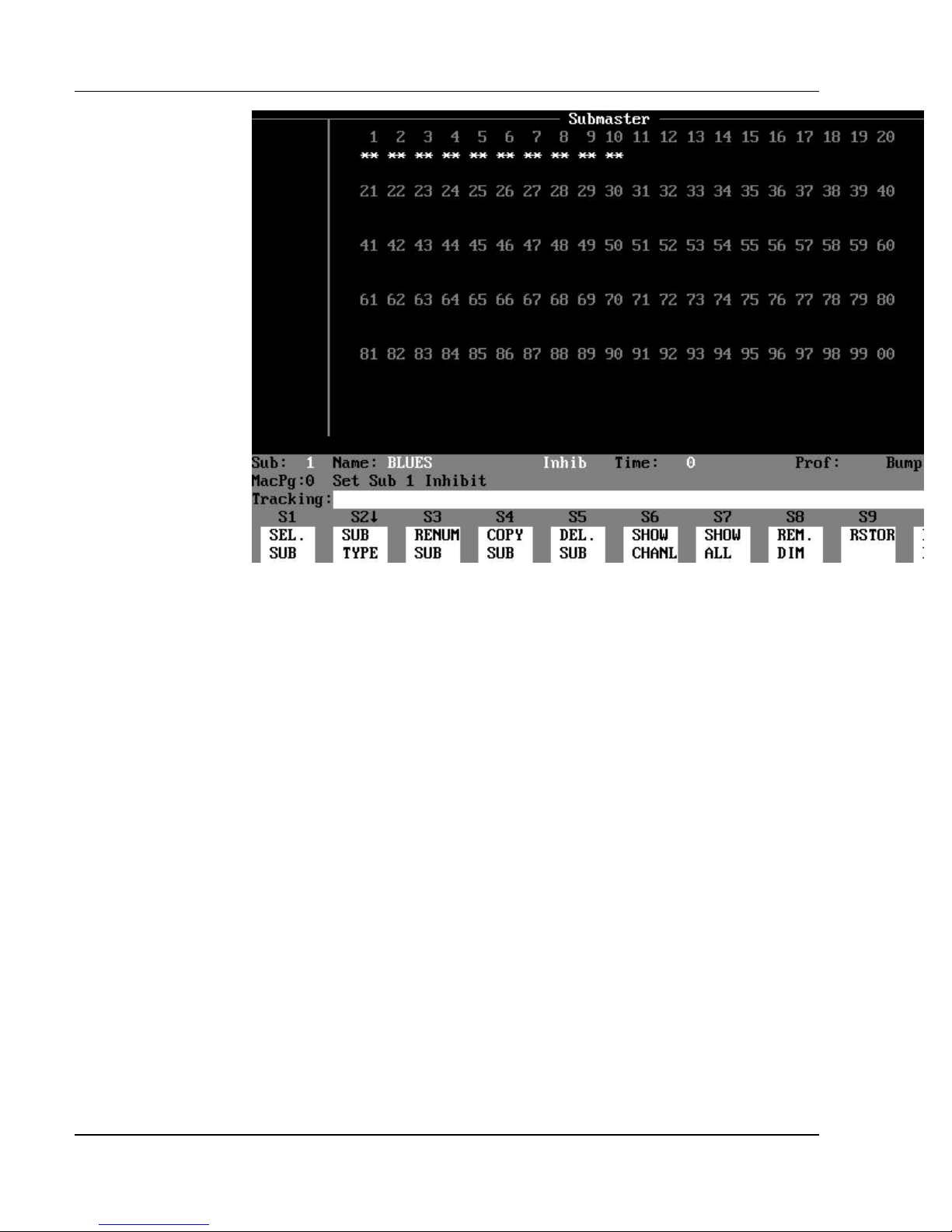
Figure 3.9, Inhibitive Submaster Display
Contents of the Inhibitive Submaster Display: In the upper
part the Inhibitive Submaster display, the symbol "**" appears under the
inhibited channels, instead of channel levels. (See Figure 3.9.)
Inhibitive Submaster Status Bar: The only difference from the
Normal Submaster Status Bar is that the “sub type” field shows "Inhib" in red
letters, instead of "Normal".
Software Version 3.05
40
Page 55
Chapter 3: Displays
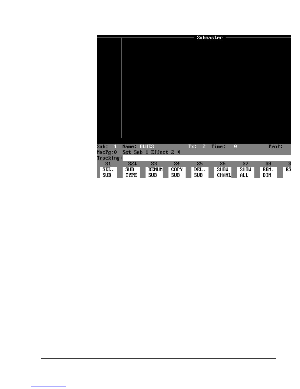
Figure 3.10, Effect Submaster Display
Contents of the Effect Submaster Display: The upper part of
the Effect Submaster display is blank - it shows neither channels nor levels.
(See Figure 3.10.)
Effect Submaster Status Bar: The only difference from the Normal
Submaster Status Bar is that the “sub type” field shows "Fx: #" in yellow
letters, indicating the effect number assigned to the submaster.
Software Version 3.05
41
Page 56
Colortran Encore Control Console
The Effect Display (a blind display)
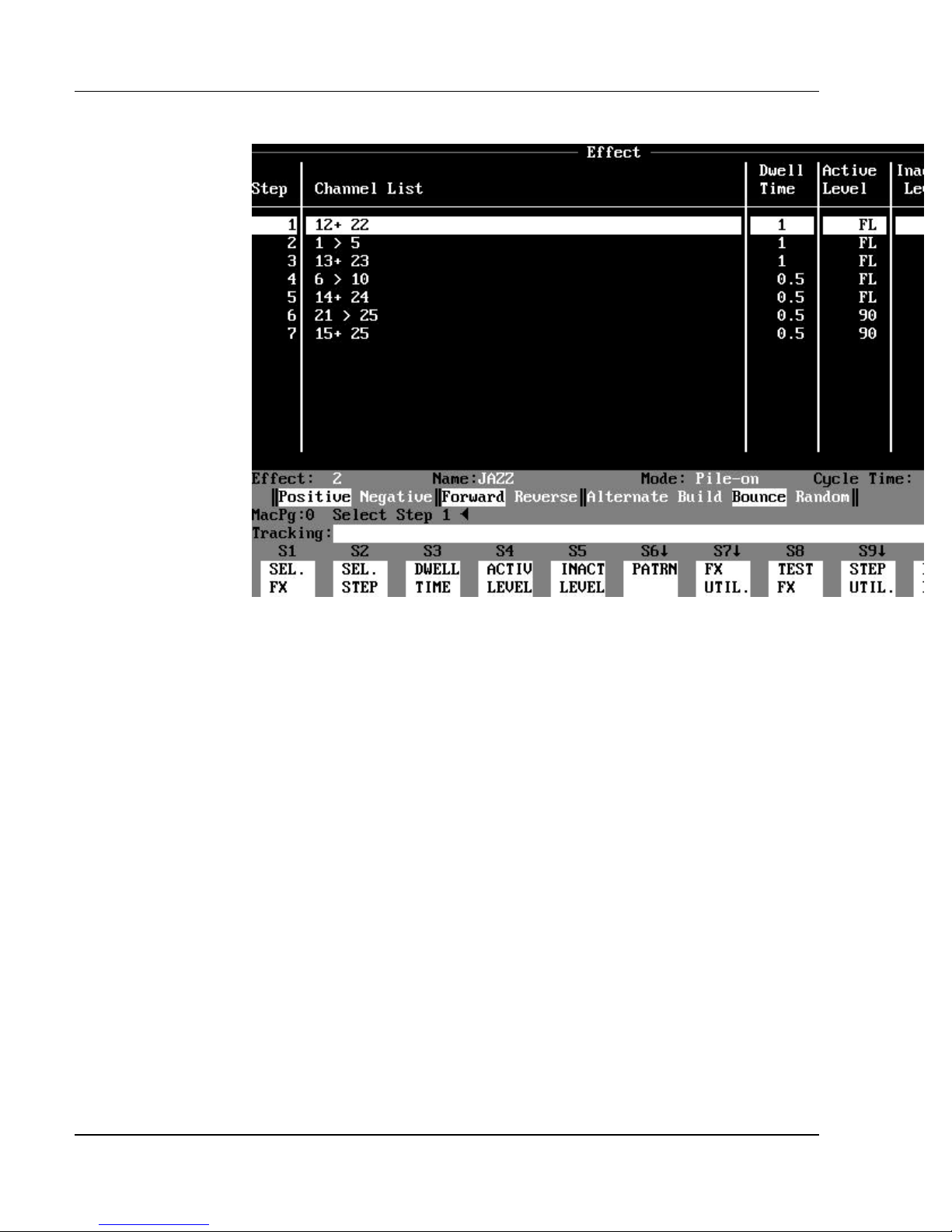
Figure 3.11, Effect Display
Purpose of the Effect Display: The Effect display creates, edits
and tests effects. The Effect display shows a list of all channels used in each
step of the effect, as well as the timing and level information.
Contents of the Effect Display: The main part of the Effect display
consists of five columns of information about the current effect as follows:
?? Step shows the step numbers (up to 99) of an effect. When an effect is
executed, each step executes
one after another. After the last step, the sequence repeats again from first to
last, for as long as the effect continues to run.
?? Channel List shows the channels assigned to each step.
?? Dwell Time shows the length of time each step is active.
?? Active Level shows the level of the channels when the step is active.
?? Inactive Level shows the level of the channels when the step is inactive.
Software Version 3.05
42
Page 57

Chapter 3: Displays
HINT: In the Effect display, use the Position Keypad as follows:
?
1. Use the Up and Down arrow keys to select individual steps in
the effect currently being edited. The Down Arrow key will
also create steps
2. Use the [NEXT] and [LAST] keys to view different effects.
3. Use the [PAGE UP] and [PAGE DOWN] keys to view steps
that are out of view of the display
Status Bar: The Status Bar is located just below the main information
area. The Status Bar contains the following fields for information:
?? Effect: shows the number of the current effect being viewed and edited.
?? Name: shows the name of the current effect.
?? Mode: shows the effect mode, either "Pile-on", or "Take Control".
?? Cycle Time: shows the amount of time it takes to execute all the steps
of the effect once (the sum
of all the Dwell Times).
Pattern Bar: The Pattern Bar is directly below the Status Bar, and shows
the choice of patterns available for the current effect. Selected patterns appear
as black text in a gray background. More than one pattern may be selected
simultaneously. The choice of effect patterns available in the Pattern Bar is
listed below:
?? Positive / Negative
?? Forward / Reverse
?? Alternate
?? Build
?? Bounce
?? Random
Command Line / Command Line History: Directly below the
Status Bar are the Command Line History and the Command Line. The
Command Line displays the command currently being entered. The Command
Line History shows the last command executed.
Soft Key Labels: The Soft Key Labels are located directly below the
Command Line. The Soft Key Labels describe the function of each soft key.
The function commands are executed by pressing one of the soft keys, (S1) (S10), on the console. The functions of the soft keys change for each display.
Software Version 3.05
43
Page 58
Colortran Encore Control Console
The Cuesheet Display (a blind display)
Figure 3.12, Cuesheet Display
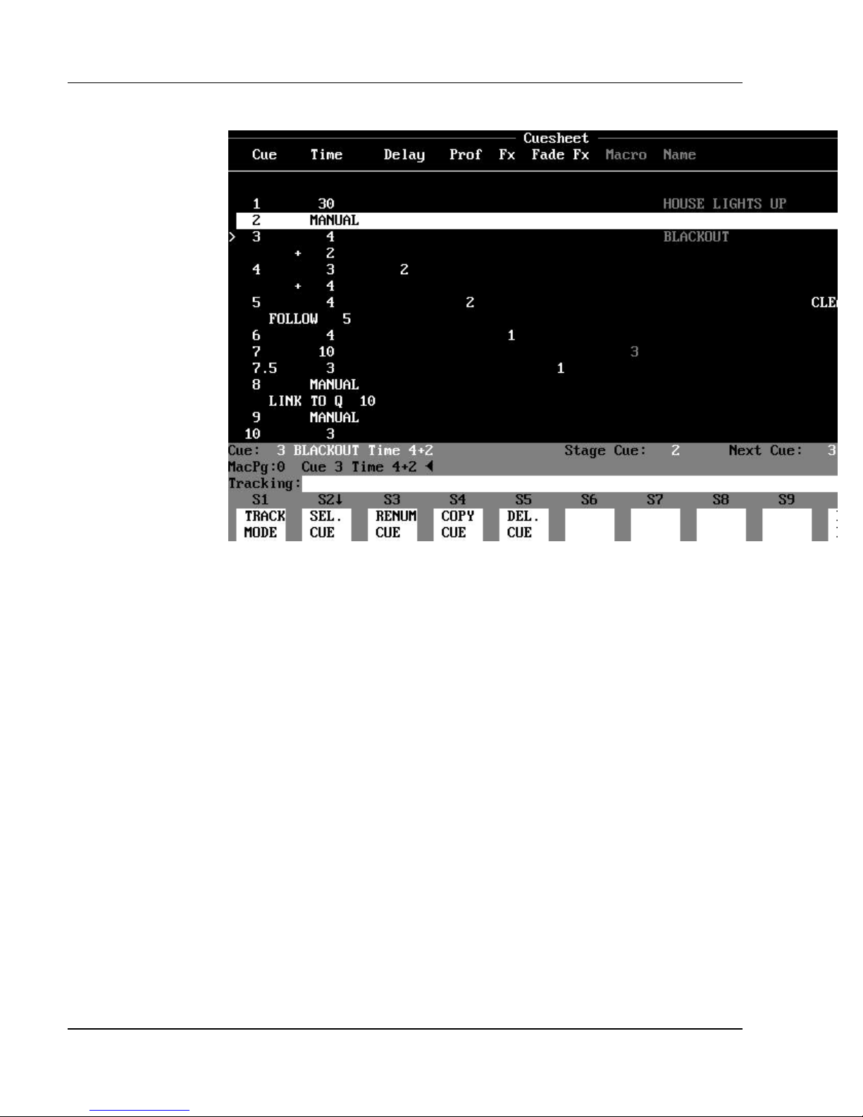
Purpose of the Cuesheet Display: The Cuesheet display is used
to view the cue order and cue attributes. Cues may be Deleted, Copied, or
Renumbered. Cue attributes may also be edited.
Contents of the Cuesheet Display: The main area of the
Cuesheet display contains six columns listing cue data and attributes. The
information in each column is described below:
?? Cue shows the cue numbers and any part numbers.
?? Time shows the time assigned to the cue/part.
?? Delay shows any delay assigned to the cue/part.
?? Prof shows any profile assigned to the cue/part.
?? Fx shows any effect number assigned to the cue/part.
?? Fade Fx shows any fade effect assigned to the cue/part.
?? Macro shows any macro assigned to the cue/part.
?? Name shows the name assigned to the cue.
?? “CLEAN UP” shows when any cue is a Clean Up cue.
?? “>" to the left of the Cue column indicates the current "preview" cue.
This is the default cue for any cue attribute edit commands that do not specify a
cue number.
? NOTE: The number and attributes of the current stage cue (last cue
to be executed) appear in reverse video in a gray band across the screen.
Software Version 3.05
44
Page 59

Chapter 3: Displays
? NOTE: Information about cue follows, links, link repeats, and link
returns appears below the timing information about the cue.
Status Bar: The Status Bar is located below the main channel and level
information area. The Status Bar contains the following fields for information:
?? Cue: shows the current cue being viewed and edited.
?? Stage Cue: shows the last cue executed on stage.
?? Next Cue: shows the next cue number to be executed by pressing the
GO button.
?? Mac Pg: shows the number of the macro page (0 - 9) currently being
accessed.
Command Line / Command Line History: Directly below the
Status Bar are the Command Line History and the Command Line. The
Command Line displays the command currently being entered. The Command
Line History shows the last command executed.
Soft Key Labels: The Soft Key Labels are located directly below the
Command Line. The Soft Key Labels describe the function of each soft key.
The function commands are executed by pressing one of the soft keys, (S1) (S10), on the console. The functions of the soft keys change for each display.
Cuesheet Display Paging Rules: The rules for paging through the
Cuesheet display are as follows:
1. Up and Down Arrow keys ([?] and [?]) scroll through the cue list one
cue at a time.
2. [PAGE UP] and [PAGE DOWN] scroll through the cue list one full
page at a time.
3. [NEXT] and [LAST] select the current preview cue (indicated by the
">" symbol).
- or Press [CUE] [#] [ENTER]
4. If you change displays and then return to the Cuesheet display, the
display will be centered on the
current Preview cue (indicated by the ">" symbol).
Software Version 3.05
45
Page 60
Colortran Encore Control Console
The Tracksheet Display (a blind display)
Figure 3.13, Tracksheet Display
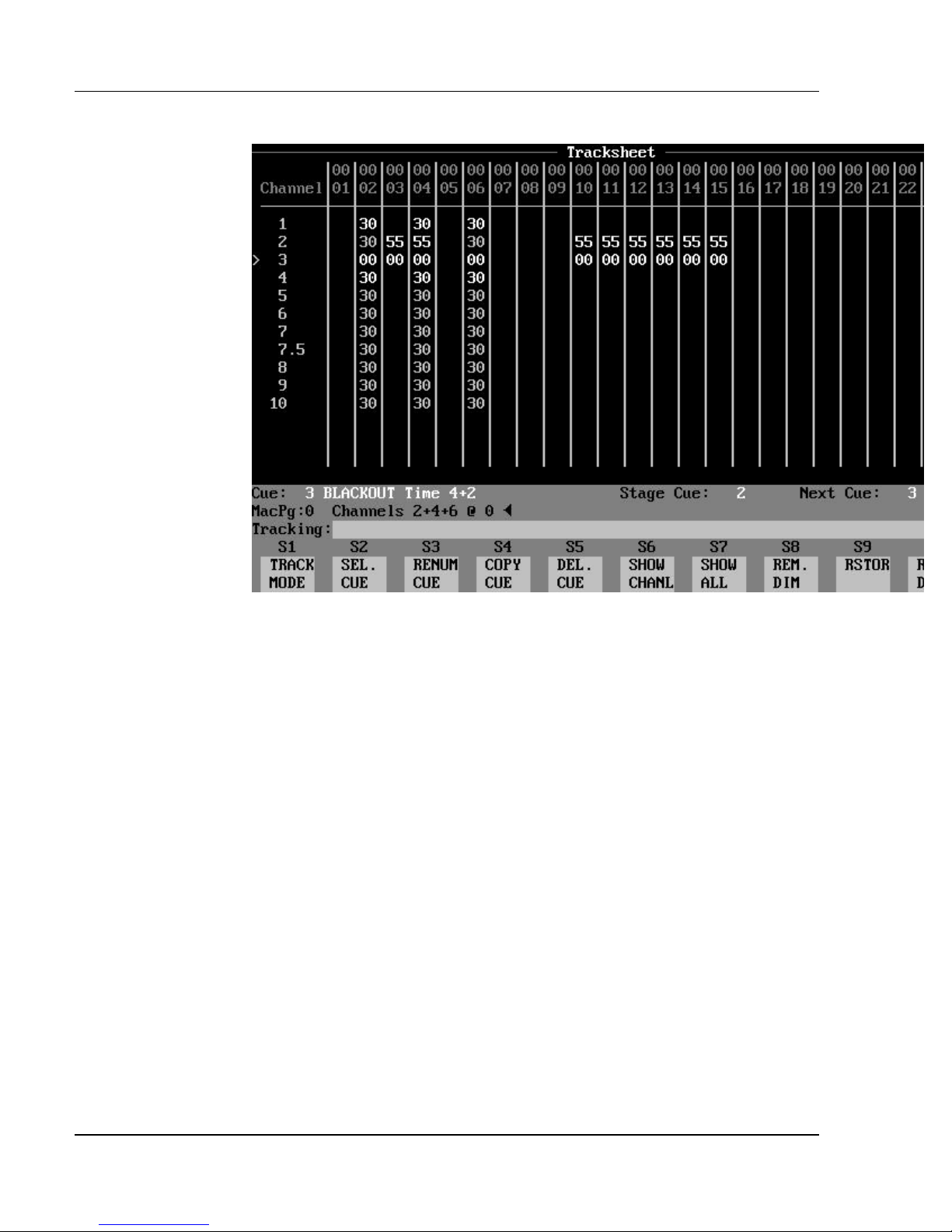
Purpose of the Tracksheet Display: The Tracksheet display is
really a giant spreadsheet that shows all channel levels of all cues, side by side,
so that channel levels of cues may be compared. In the Tracksheet display, all
edits are recorded as you make them. Cues may be created or edited in this
display. Cue attributes may also be added or edited in the Tracksheet display,
although they are not shown.
Contents of the Tracksheet Display: The top row of the display
lists the channels currently selected for viewing. The cue and any part number
appear in the far left column of this display, with the channel levels in the cue
shown in the same row. When a cue is currently selected for editing, the ">"
symbol appears next to its cue number.
Below each channel number is a column of levels, representing the level of that
channel in each cue (if no level is visible, then the level is zero). Non-tracking
(hard) levels are shown in white. Tracking (soft) levels are shown in gray. If
the track mode is Clean Up, then all hard zeros disappear, and all levels appear
white. If the track mode is Cue Only or Tracking then the channels levels are
shown in the following two colors:
?? white = Hard (non tracking) levels
?? gray = Soft (tracking) levels
Software Version 3.05
46
Page 61

Chapter 3: Displays
Status Bar: The Status bar is located just below the channel and level
information in the main part of the display. The Status Bar contains the
following fields of information:
?? Cue: shows the current preview cue being edited, and the cue attributes.
?? Stage Cue: shows the last cue executed on stage.
?? Next Cue: shows the next cue number to be executed when the GO
button is pressed.
?? Mac Pg: shows the number of the macro page (0 - 9) currently being
accessed.
Command Line / Command Line History: Directly below the
Status Bar are the Command Line History and the Command Line. The
Command Line shows the command currently being entered. The Command
Line History shows the last command executed.
Track Mode: The current Track mode (Cue Only, Tracking, or Clean Up)
appears at the far left of the Command Line.
Soft Key Labels: The Soft Key Labels are located directly below the
Command Line. The Soft Key Labels describe the function of each soft key.
The function commands are executed by pressing one of the soft keys, (S1) (S10), on the console. The functions of the soft keys change for each display.
Tracksheet Display Paging Rules: The rules for paging through
the Tracksheet display are as follows:
1. To scroll the list of cues up or down one line at a time, press the Up
and Down Arrow keys.
2. To scroll the list of cues up or down one page at a time, press the
[PAGE UP] and
[PAGE DOWN] keys.
3. To select a different cue for editing, press the [NEXT] and [LAST]
keys.
- or -
Press [CUE] [#] [ENTER].
4. To show a different range of channels across the top of the display,
press the Left and Right Arrow keys.
? NOTE: When you press [CUE] [#] [ENTER], a new cue is created if
the cue does not already exist.
Software Version 3.05
47
Page 62

Colortran Encore Control Console
HINT: If you enter a channel number in the currently selected edit
?
cue, the display will automatically page to the channel location in the
Tracksheet display.
Software Version 3.05
48
Page 63
Chapter 3: Displays
The Playback Display (a live display)
Figure 3.14, Playback Display
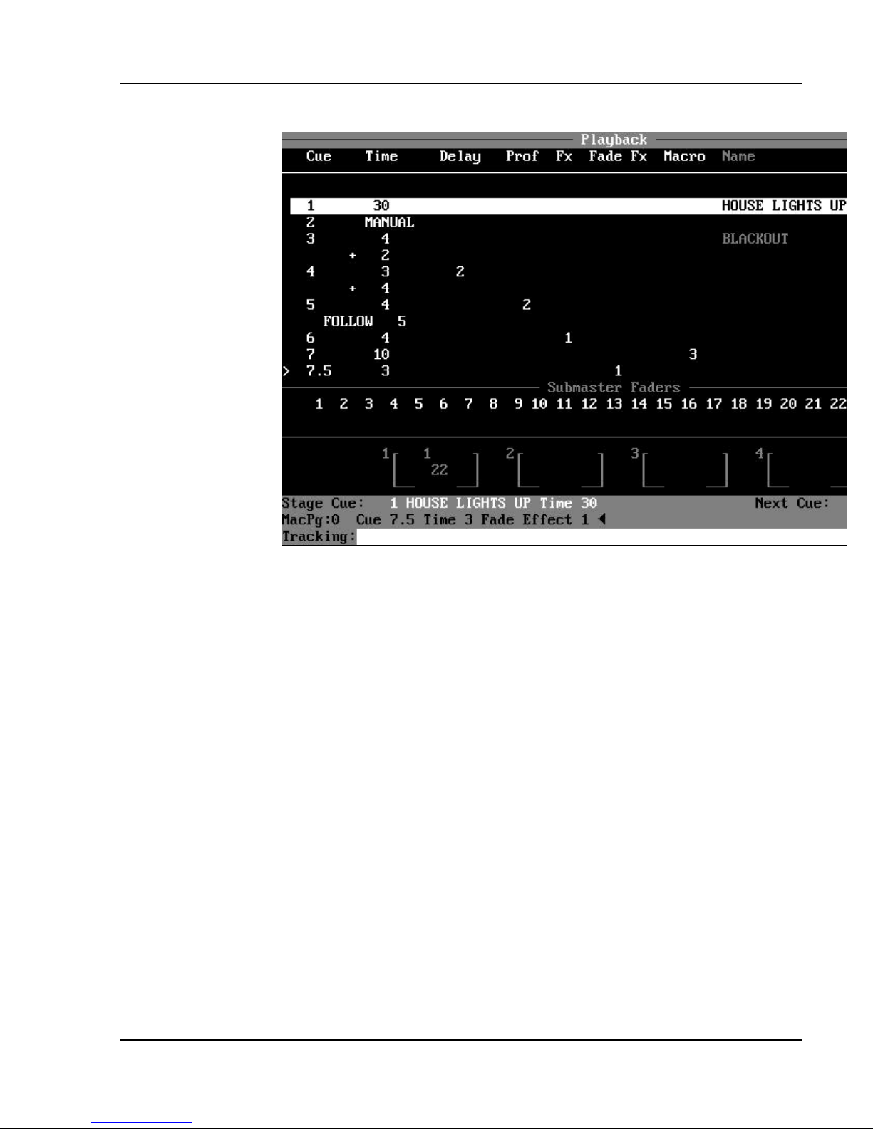
Purpose of the Playback Display: The Playback display is used to
view the current status of any running cues and active submasters. The
Playback display shows previous, current, and upcoming cue numbers, while
the Stage display shows the channel levels of fading cues. A limited number of
stage channels can also be shown in the Playback display.
Contents of the Cuesheet Area: The upper area of the Playback
display is the Cuesheet Area, which consists of eight columns listing each cue
and its attributes. This information is identical to the Cuesheet display, except
that in the Playback display:
?? The current stage cue (shown in reverse video in a horizontal gray band)
automatically remains
centered in the Cuesheet Area.
?? You cannot page through the cue list, as in the Cuesheet display.
?? You can select how many rows of cues you want to view on the screen at
one time. Any remaining
space shows stage levels.
You can select the number of cue rows you want to see in the Cuesheet Area by
pressing the
(CUE ROWS) soft key under the Display Setup (DISP. SETUP) soft key in the
Setup display.
Software Version 3.05
49
Page 64
Colortran Encore Control Console
HINT: The (CUE ROWS) soft key also exists as a "hidden" soft key
?
in the Playback display, under (S1).
HINT: Selecting the number of cues rows shown in the Cuesheet
?
Area may work best when you are using the compressed text display mode (43
lines per page).
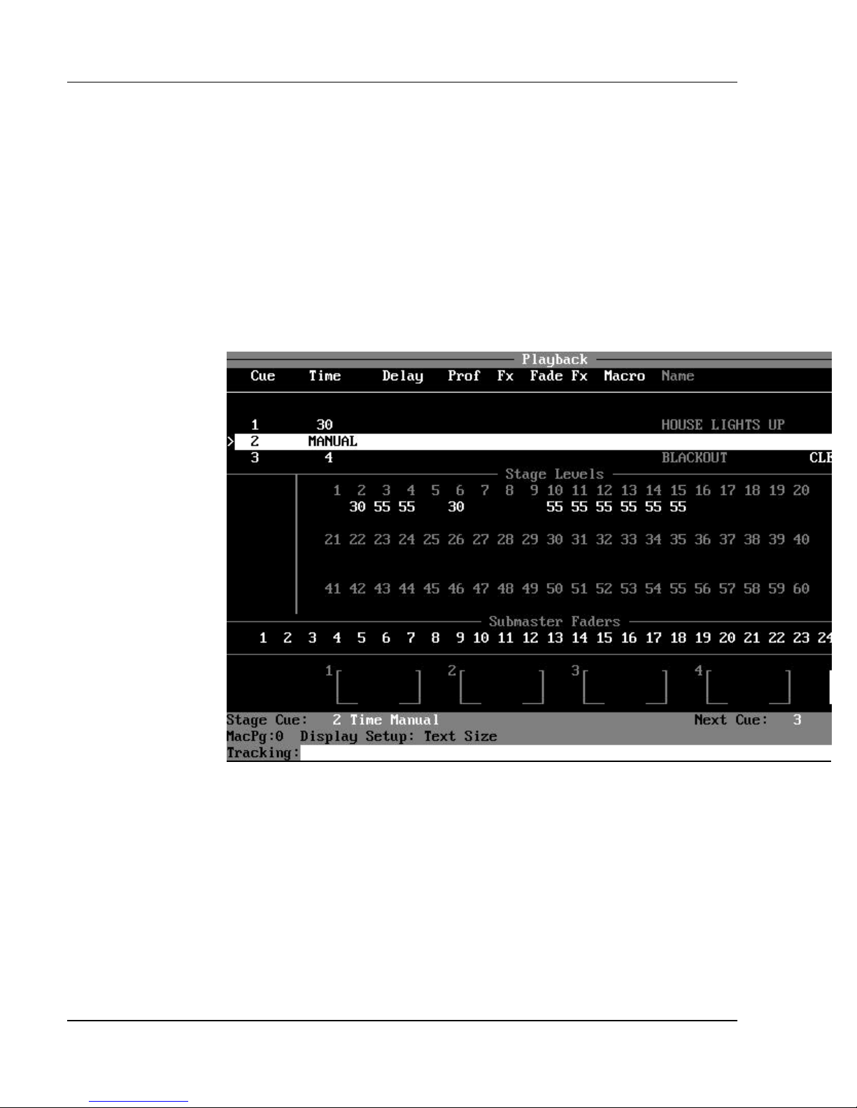
Figure 3.15, Stage Levels in Playback Display
Stage Levels Window: The Playback display also allows you to view
live stage levels. The number of rows of cuesheet information shown in the
Cuesheet Area can be specified in the Setup display by pressing the (DISP
SETUP) and (CUE ROWS) soft keys. If fewer rows are specified than are
available in the display, the extra rows are used to show live stage channel
levels. This feature is especially effective when you are using the compressed
(43-line) text display mode, when you can have many more rows on the screen
than in the uncompressed (27-line) text display mode.
Submaster Fader Window: The Submaster Fader numbers are listed
sequentially in rows, below the cuesheet area. Below the Submaster Fader
Software Version 3.05
50
Page 65

Chapter 3: Displays
numbers are their current level readings. If no level is present, the submaster
fader is all the way down at zero.
The Submaster Fader Window has its own Compressed and Uncompressed
modes. In Uncompressed mode, the submaster levels appear below their
respective submaster fader numbers, as described above. (See Figure 3.14). In
Uncompressed mode, only the sequential submaster numbers are shown. If a
submaster is active, it is shown in reverse video. (See Figure 3.15). To toggle
between Compressed and Uncompressed mode in the Setup display, press the
Submaster Window (SUB WNDOW) soft key under the Display Setup (DISP.
SETUP) soft key.
HINT: The (SUB WNDOW) soft key also exists as a "hidden" soft key
?
in the Playback display, under (S10).
The Submaster Fader numbers are shown in different colors according to the
following code:
?? white = Normal (pile-on) submaster
?? yellow = Effect loaded on submaster
?? red = Inhibitive submaster
?? gray = Unassigned "empty" submaster
When the Submaster Fader Window is uncompressed, the submaster levels are
shown in different colors to show where the submaster levels originate
according to the following code:
?? gray = Manual level controlled by submaster fader
position.
?? red = Level faded up (or fading up) by the Bump
button.
?? blue = Level faded down (or fading down) by the Bump
button.
When the Submaster Window is compressed, submaster levels above zero are
indicated by a reverse video box around the submaster number.
? NOTE: In compressed mode, Inhibitive subs are shown in reverse
video anytime their levels are less than Full (when they are actively
“inhibiting” channels).
Playback Fader Boxes: The four Playback Fader Boxes, numbered 1
- 4, are located below the Submaster Fader Window on the Playback display
screen. The Playback Fader Boxes indicate the current status of any cues
actively fading. When a cue is executed by pressing the GO button or the [GO
Software Version 3.05
51
Page 66

Colortran Encore Control Console
TO CUE] key, the cue is automatically loaded onto the lowest available
playback fader. The Playback Fader Boxes work exactly the same as in the
Stage display. (See the Stage display section, earlier in this chapter.)
Software Version 3.05
52
Page 67

Chapter 3: Displays
Grandmaster Fader Box: To the right of the Playback Fader Boxes is
the Grandmaster Fader Box. It indicates the level of the Grandmaster,
anywhere from 100% (FL=Full Level) to 0% (B.O.=Black Out). The Blackout
switch will also cause this indicator to read "B.O.". The Grandmaster level
blinks anytime it is set below Full.
Status Bar: The Status Bar is located just below the channel and level
information in the main part of the display. The Status Bar contains the
following fields of information:
?? Stage Cue: shows the last cue executed on stage.
?? Next Cue: shows the next cue number to be executed by pressing the
GO button.
?? Mac Pg: shows the number of the macro page (0 - 9) currently being
accessed.
?? Dimmers Parked message only shows when there are dimmers
currently parked.
Track Mode: The current Track mode (Cue Only, Tracking, or Clean Up)
appears at the far left of the Command Line.
Command Line / Command Line History: Directly below the
Status Bar are the Command Line History and the Command Line. The
Command Line displays the command currently being entered. The Command
Line History shows the last command executed.
Playback Display Paging Rules: The rules for paging through the
Playback display are as follows:
1. To scroll the list of stage channels up or down one line at a time,
press the Up and Down Arrow keys.
2. To scroll the list of stage channels up or down one page at a time,
press the [PAGE UP] and [PAGE DOWN] keys.
3. To select a different preview cue for editing, press [CUE] [#]
[ENTER]. (The cue may or may not be visible from the Playback display.)
4. The cuesheet area of the Playback display always stays centered on the
current stage cue.
Soft Keys: Although no soft keys are shown in the Playback display, there
are four "hidden" soft keys that function in this display. These hidden soft keys
are the same soft keys that appear under the (DISP. SETUP) soft key in the
Setup display, as shown below:
?? S1: (CUE ROWS) = Defines how many rows of information
are shown in
the Playback display.
Software Version 3.05
53
Page 68

Colortran Encore Control Console
?? S2: (TEXT SIZE) = Toggles between 25 and 43-line display
modes.
?? S3: (COPY RIGHT = Shows the copyright notice.
?? S4: (SUB WNDOW) = Toggles submaster window between
Expanded and
compressed modes.
Software Version 3.05
54
Page 69
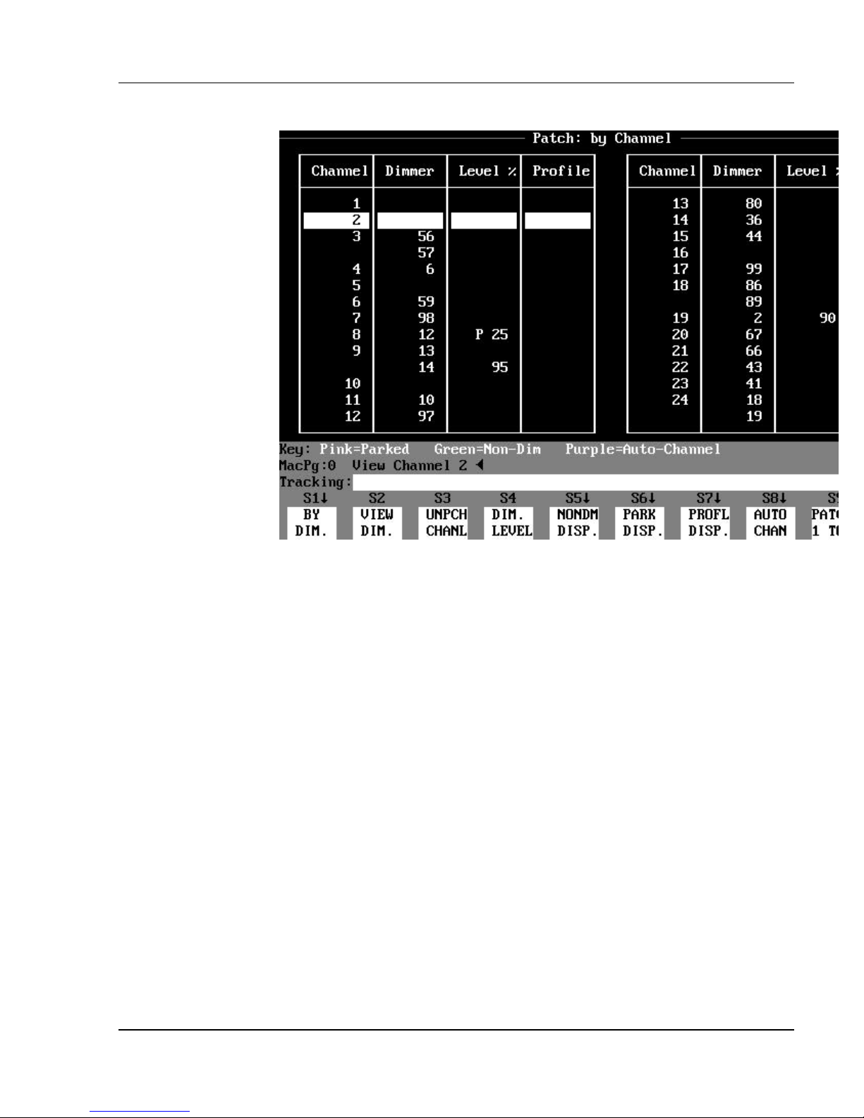
Chapter 3: Displays
The Patch Display (a blind display)
Figure 3.16, Patch: By Channel Display
Purpose of the Patch display: The Patch display shows and allows
editing of channel-to-dimmer assignments. One channel can control any
number of dimmers. The Patch display has four different display modes:
?? Patch: By Channel display shows the patch table in channel order. (See
Figure 3.16.)
You can edit channel-to-dimmer assignments in this mode.
?? Patch: By Dimmer display shows the patch table in dimmer order. (See
Figure 3.17.)
You can edit channel-to-dimmer assignments in this mode.
?? Patch: Non-Dim Dimmers subdisplay shows all virtual non-dim
dimmers. (See Figure 19.1.)
You can assign dimmers as virtual non-dims in this mode.
?? Patch: Parked Dimmers subdisplay shows all parked dimmers. (See
Figure 19.2.)
You can park and unpark dimmers in this mode.
Software Version 3.05
55
Page 70
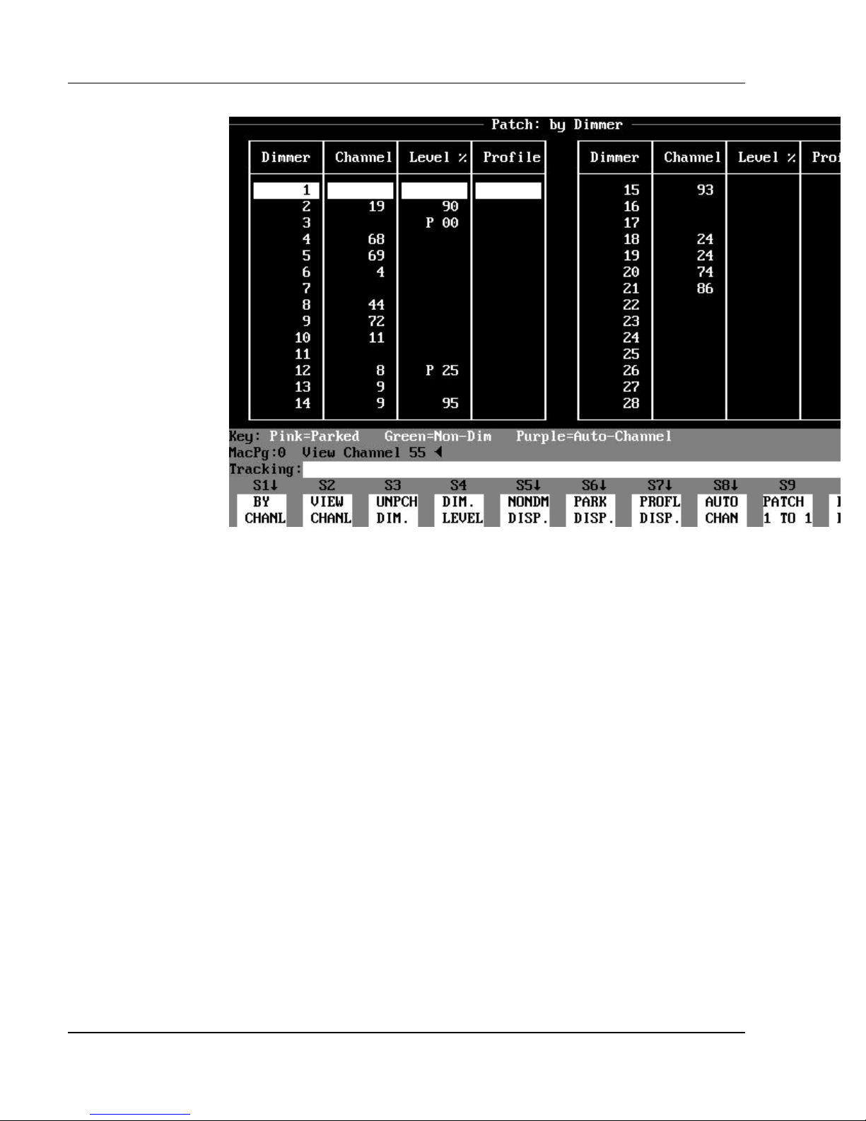
Colortran Encore Control Console
Figure 3.17, Patch: By Dimmer Display
Press the (S1) key to toggle between the Patch: By Channel and Patch: By
Dimmer displays. Press the (NONDM DISP.) soft key to see the Patch: NonDim Dimmers subdisplay. Press the (PARK DISP.) soft key to see the Patch:
Parked Dimmers subdisplay.
? NOTE: (S1) is the (BY DIM.) soft key in the Patch: By Channel
display. (S1) is the (BY CHANL) soft key in the Patch: By Dimmer display.
Software Version 3.05
56
Page 71

Chapter 3: Displays
Contents of the Patch Display: The main upper portion of the
Patch display consists of two tables of four columns each (each table is a
sequential continuation of the information). The four columns of data in Patch:
By Channel mode are listed sequentially by channel as follows (in Patch: By
Dimmer mode, the first and second columns are swapped):
?? Column 1, Channel, lists the channels in sequential order.
?? Column 2, Dimmer, lists the dimmers assigned to each channel.
?? Column 3, Level %, shows the current proportional level, or parked
level of the dimmer.
?? Column 4, Profile, shows the Profile number assigned to the dimmer (if
any).
Below the two tables is a key indicating the colors used in this display as
follows:
?? pink = Parked dimmer
?? green = Virtual Non-Dim dimmer
?? purple = Automated channel
? NOTE: When a dimmer is parked, a "P" appears to the left of the
parked level in the Level % column, and the level is shown in pink.
ADVANCED TOPICS: For more information on Parked dimmers,
?
Virtual Non-Dim dimmers, and Automated channels, see Chapter 20,
Advanced Patching Options.
Command Line / Command Line History: Directly below the
Status Bar are the Command Line History and the Command Line. The
Command Line displays the command currently being entered. The Command
Line History shows last the command executed.
Track Mode: The current Track mode (Cue Only, Tracking, or Clean Up)
is shown at the far left of the Command Line.
Soft Key Labels: The Soft Key Labels are located directly below the
Command Line. The Soft Key Labels describe the function of each soft key.
The function commands are executed by pressing one of the soft keys, (S1) (S10), on the console. The functions of the soft keys change for each display.
Software Version 3.05
57
Page 72
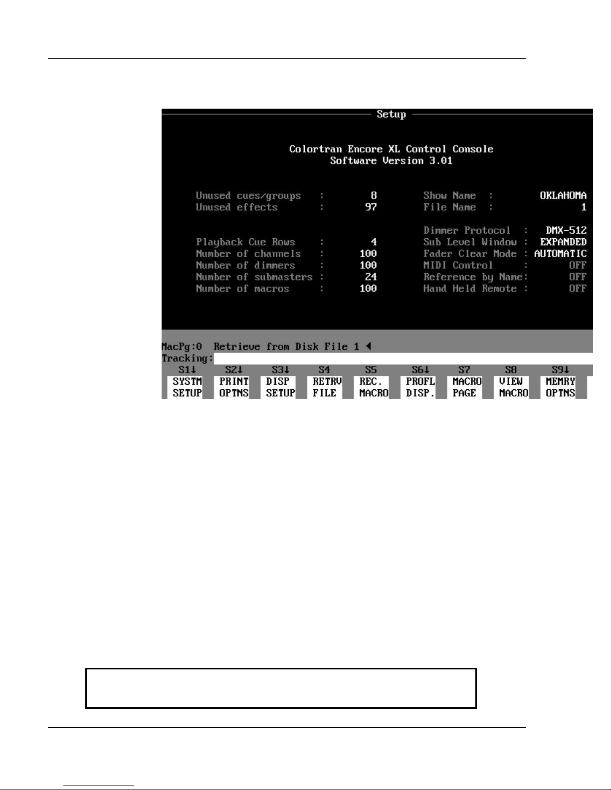
Colortran Encore Control Console
The Setup Display (a blind configuration
display)
Figure 3.18, Setup Display
Purpose of the Setup Display: The Setup display is used to
customize show parameters to suit your specific needs. All editable parameters
shown in the Setup display are edited through the soft keys available in this
display. The Setup display shows all the current setup parameters for a show.
These parameters include:
?? Show Name (this is different from the File Name)
?? Number of dimmers (total) for the show
?? Number of channels (total) for the show
?? Dimmer Protocol that is currently selected
Printing and memory functions are also performed in the Setup display.
Contents of the Setup Display: Your Encore model and software
version number are shown at the top of the Setup display. Below this are the
Show Name and File Name of the currently loaded show. The information
fields in the Setup display are summarized in Table 3.1 on the next page.
Unused cues / groups Number of cues, cue parts and groups available to record in show.
Unused effects Number of effects available to record in show.
Software Version 3.05
58
Page 73

Chapter 3: Displays
Playback Cue Rows Number of rows of cue information shown in the Playback display.
Number of channels Total channels configured in your show.
Number of dimmers Total dimmers configured in your show.
Number of submasters Total submasters in your Encore model.
Number of macros Total macros in your Encore model.
Show Name The name of the show currently loaded in the console.
File Name The file name of the show currently loaded in the console.
(This is the file name used on the floppy disk.)
Dimmer Protocol Protocol selected (DMX-512 or CMX).
Sub Level Window EXPANDED or COMPRESSED sub window in Playback display.
Fader Clear Mode AUTOMATIC or MANUAL
MIDI Control Device # or OFF
Reference by Name ON or OFF
Hand Held Remote ON or OFF
Table 3.1, Setup Display Information Fields
Display Formatting Options: Display formatting options are
changes to the display appearance that you can configure. The display
formatting options are:
?? Number of cue rows shown (See Playback Display topic in this
chapter.)
?? Text size (See Text Size topic, below.)
?? Submaster Fader Window size (See Playback Display topic in this
chapter.)
?? Channel formatting (See Basic Display topic, at the
beginning of this chapter.)
Text Size: Pressing the (TEXT SIZE) soft key toggles between the two
different display modes: 27 lines per page, and 43 lines per page. The (TEXT
SIZE) soft key is available under the Display Setup (DISP. SETUP) soft key.
HINT: The Compressed text size mode is useful when you need a lot
?
of information on the screen.
Submaster Fader Window: The Submaster Fader Window in the
Playback display can be toggled between Expanded mode and Compressed
mode by pressing the Submaster Window (SUB WNDOW) soft key, available
under the Display Setup (DISP. SETUP) soft key. The Expanded mode shows
Software Version 3.05
59
Page 74

Colortran Encore Control Console
the submasters and their current levels. The Compressed mode shows only the
submaster numbers without their levels. When the Submaster Fader Window is
in Compressed mode, an active submaster is shown in reverse video.
Profile Editor Subdisplay: A profile is a method of customizing an
output curve assignment, which may be assigned any number of times to
different cues or dimmers. The Profile Editor subdisplay is available under the
Profile Display (PROF. DISP.) soft key.
ADVANCED TOPICS: See Chapter 18, Profiles.
?
Track Mode: The current Track mode (Cue Only, Tracking, or Clean Up)
appears at the far left the Command Line. The Track mode applies when you
use the memory functions available in the Setup display.
Command Line / Command Line History: Directly below the
Status Bar are the Command Line History and the Command Line . The
Command Line displays the command currently being entered. The Command
Line History shows the last command executed.
Soft Key Labels: The Soft Key Labels are located directly below the
Command Line. The Soft Key Labels describe the function of each soft key.
The function commands are executed by pressing one of the soft keys, (S1) (S10), on the console. The functions of the soft keys change for each display.
Software Version 3.05
60
Page 75
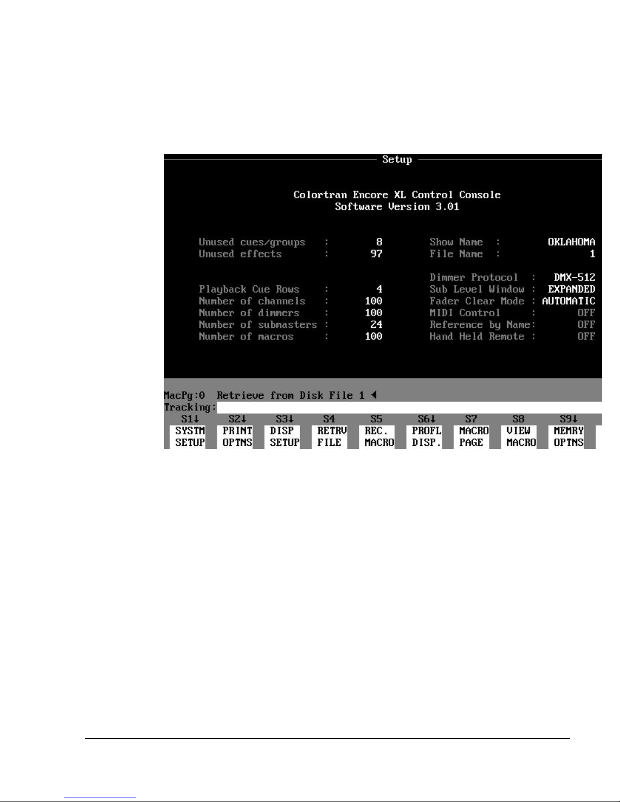
CHAPTER 4:
Console System Setup
Figure 4.1 Setup Display
Using the Setup Display
The Setup display gives you a way to configure the console to match your
overall system. In the Setup display you can also change fundamental control
settings, and execute printing and file management tasks. In the Setup display,
you can perform the tasks listed below:
?? Modify system settings
(Discussed in this chapter.)
?? Modify display parameters
(See Playback and Setup Display topics in Chapter 3, Displays. )
?? Change displays on the optional auxiliary monitor
(See Appendix G, Auxiliary Monitor.)
Software Version 3.05
61
Page 76
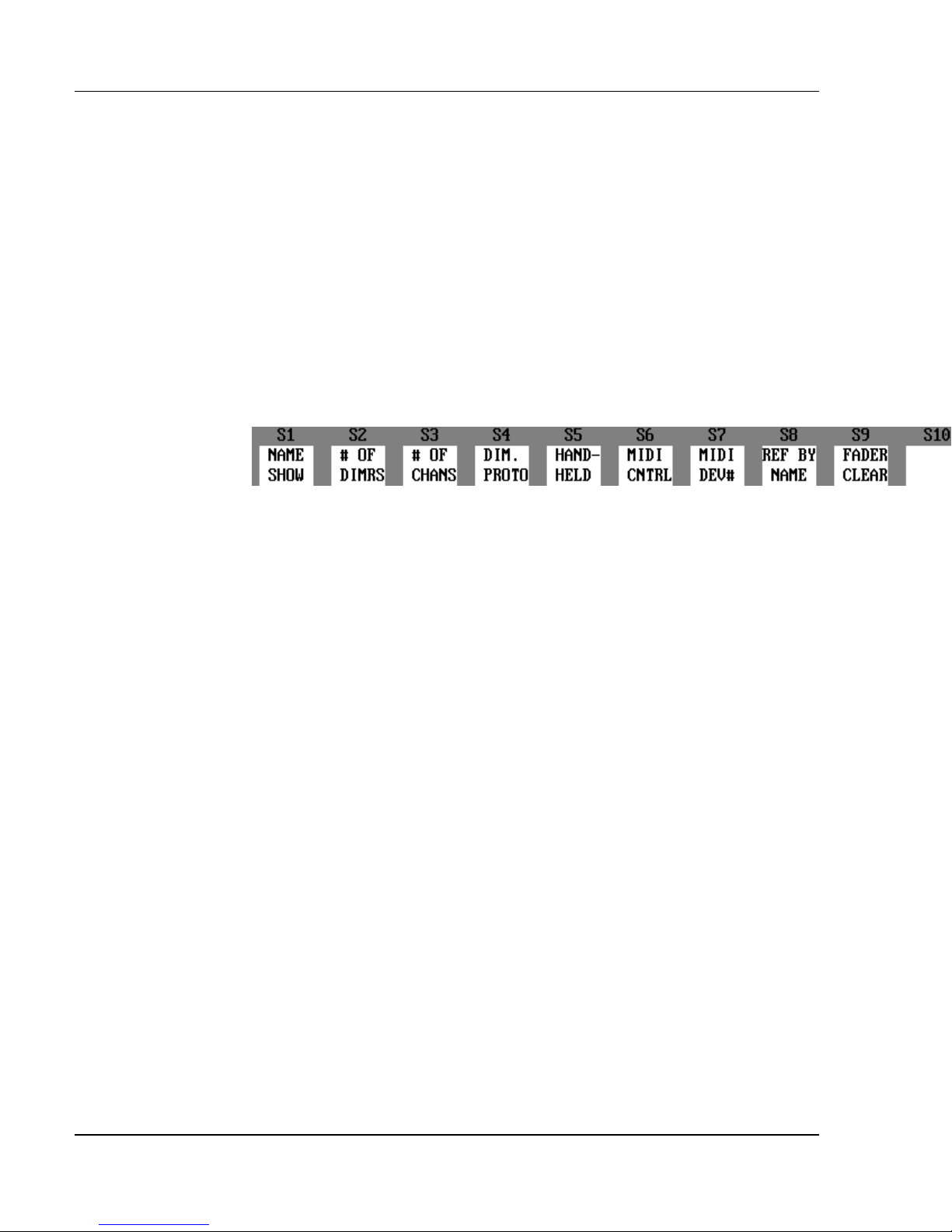
Colortran Encore Control Console
?? Execute printing commands
(See Chapter 12, Utilities, Warnings, Printing, and Default Settings.)
?? View console active memory space
(See Chapter 13, Memory.)
?? Save, view, copy, delete, and retrieve show files from floppy disks
(See Chapter 13, Memory.)
?? Record macros, select the current Macro Page, and view macro contents
(See Chapter 21, Macros.)
In this chapter we discuss the options available to you under the (SYSTM
SETUP) soft key. See the appropriate chapter for information about the other
topics listed.
Figure 4.2 System Setup Soft Keys
System Setup
In the System Setup, you can use the soft keys shown in Figure 4.2 to define the
number of dimmers and channels used in a show, as well as enable or disable
peripheral devices such as the Hand Held Remote or the MIDI interface.
System Setup assignments remain in memory even after the console is turned
off and then turned back on again. When console memory is cleared, the
System Setup assignments are reset to the factory defaults. The dimmer
protocol selection however, always retains its assignment when the console
memory is cleared.
ADVANCED TOPIC: For more information about how System
?
Setup assignments are held in memory, see the System Settings In Memory
topic in Chapter 13, Memory.
Show Name
The (NAME SHOW) soft key provides a way to add an additional alphanumeric label to a show file. The Show Name is different than the show File
Name. The Show Name only appears in the Setup display, and can only be
viewed when the show is in active memory.
Software Version 3.05
62
Page 77
Chapter 4: Console System Setup
? EXAMPLE: To assign a Show Name to a show in the Setup display:
1. (SYSTM SETUP)
2. (NAME SHOW) [enter alpha-numeric show name] [ENTER]
ADVANCED TOPICS: To name your show files using alphabet
?
characters, see Chapter 11, Names.
Console Model Channel Capacity Dimmer Capacity
24/48 24 in 2-Scene mode
144 in Multi-Scene mode
24/48 Expanded 24 in 2-Scene mode
512 in Multi-Scene mode
48/96 48 in 2-Scene mode
144 in Multi-Scene mode
48/96 Expanded 48 in 2-Scene mode
512 in Multi-Scene mode
XL 512 512
XL/2 1024 1024
Table 4.1, Console Channel / Dimmer Capacities
512
512
512
512
Number of Channels and Dimmers
The maximum number of control channels and dimmer channels available is
determined by the model of Encore console you are using. (See Table 4.1.)
You may select a lesser number of channels and dimmers by using the (# OF
CHANS) soft key or the (# OF DIMRS) soft key under the (SYSTM SETUP)
soft key. These commands address the console globally, reducing the number
of channels shown in all displays.
? NOTE: The number of channels and dimmers may be customized
without clearing memory. If you reduce the number of channels or dimmers,
and restore them later, the previous patch assignments will be remembered. If
you increase the number of channels or dimmers in a show that was read from
disk, any previously assigned Non-Dim or Parked dimmers will be
remembered, but patch assignments will not be remembered. See Chapter 5,
Setting Up The Soft Patch.
? EXAMPLE: To set up a show with 200 channels:
1. (SYSTM SETUP)
2. (# OF CHANS) [200] [ENTER]
? EXAMPLE: To set up a show with 300 dimmers:
1. (SYSTM SETUP)
Software Version 3.05
63
Page 78

Colortran Encore Control Console
2. (# OF DIMRS) [300] [ENTER]
? NOTE: If you need to use a dimmer protocol other than DMX512 or
CMX, (such as AMX or analog control) there are a number of commercially
available protocol converters. These can be rented or purchased from
theatrical equipment suppliers or from Colortran. For more information, call
Colortran Customer Service at (800) 959-6004.
Selecting Dimmer Protocol
You can select between two different dimmer protocols for the output of the
console: DMX512 (the USITT standard) and CMX (a.k.a. Colortran protocol).
Under the (SYSTM SETUP) soft key, every press of the (DIM. PROTO) soft
key switches between these two protocols. You do not need to use the
[ENTER] key; the change is instantaneous when you press the (DIM. PROTO)
soft key.
The console remembers the dimmer protocol setting when you turn the console
off, and even when you do a “hard clear” by holding the [CLEAR] key down
while the console boots. The dimmer protocol is not recorded to disk as part of
the Show File, and when you retrieve a show from disk, the protocol selection
does not change. There are two conditions that may cause the console to reset
the dimmer protocol selection:
?? When you update the console to new software
?? When the RAM battery is dead
If the RAM battery is dead, the console will not hold the current show in its
memory when you turn the console off.
ADVANCED TOPICS: See Chapter 13, Memory. For more
?
information about changing the RAM battery, see Appendix A, Maintenance
and Customer Service.
Hand Held Remote
The Hand Held Remote is toggled on and off with the (HAND-HELD) soft key.
When the console is turned off and then back on, the Hand Held Remote retains
its On/Off setting. The Hand Held Remote On/Off setting is not stored as part
of the show file when you record a show to disk. When you load in a show
from disk, the On/Off setting does not change.
Software Version 3.05
64
Page 79

If the Hand Held Remote is enabled while it is not connected to the console, a
message appears on the console display to indicate that the Hand Held Remote
is not connected. The message can be cleared with the [CLEAR] key. The
Setup display shows that the Hand Held Remote is enabled (On). The console
can then be addressed by the Hand Held Remote when it is later connected to
the console.
ADVANCED TOPICS: For more information on the Hand Held
?
Remote, see Appendix C, Hand Held Remote.
Chapter 4: Console System Setup
MIDI Interface
Software Version 2.04 and later support both MIDI Show Control commands
and general MIDI data messaging. Commands can be accepted and
transmitted to execute playback commands.
If your console was originally shipped with software Version 1.04 or lower, a
hardware modification is required to allow the MIDI functions to operate
correctly. (You will see a message on your monitor that indicates this if your
console is one of these initial units.) Even if your console requires the
hardware modification, you may still enable the MIDI functions on your
console under the (SYSTM SETUP) soft key, and see how the console shows
incoming and outgoing MIDI commands in the Playback display. If you
require the MIDI hardware change for your console, please contact Colortran
Field Service at (800) 959-6004.
?
see Appendix D, MIDI Interface.
Reference By Name
You can use the (REF BY NAME) soft key in the System Setup to allow
reference to cues, groups, subs, and effects by their names as well as their
numbers. Press the (REF BY NAME) soft key to enable/disable the feature. By
disabling the Reference By Name feature, you can prevent your Bump buttons
from going into alpha mode when other keys are pressed ([SUB], [GROUP],
etc.).
?
ADVANCED TOPICS: For more information about MIDI functions,
ADVANCED TOPIC: See Chapter 11, Names.
Software Version 3.05
65
Page 80

Colortran Encore Control Console
Playback Fader Clearing Modes
You can use the (FADER CLEAR) soft key in the System Setup to toggle the
Playback Fader Clearing mode between Automatic and Manual. If the Fader
Clearing mode is Automatic, the cues unload from the playback faders as they
finish. If the Fader Clearing mode is Manual, all fades do not clear from the
faders when they finish. Rather, the fades remain on the faders until the
playback fader Take Control button is pressed. Timed cues fade in their
prescribed time, but will become manual when they are complete, allowing you
to move the fader to the top of its travel to "grab" the fade and reverse its
direction manually. In either Fader Clearing mode, cues may be loaded to
faders with the GO button or the [LOAD] key.
?
Clearing mode is usually used.
HINT: In normal theatrical applications, the Automatic Fader
? EXAMPLE: To toggle the Fader Clearing mode in the Setup display:
1. (SYSTM SETUP)
2. (FADER CLEAR) (Pressing [ENTER] is not
necessary.)
?
Playback Faders in Chapter 9, Playing Back Cues.
ADVANCED TOPIC: See the topic on Clearing Fades From The
Software Version 3.05
66
Page 81
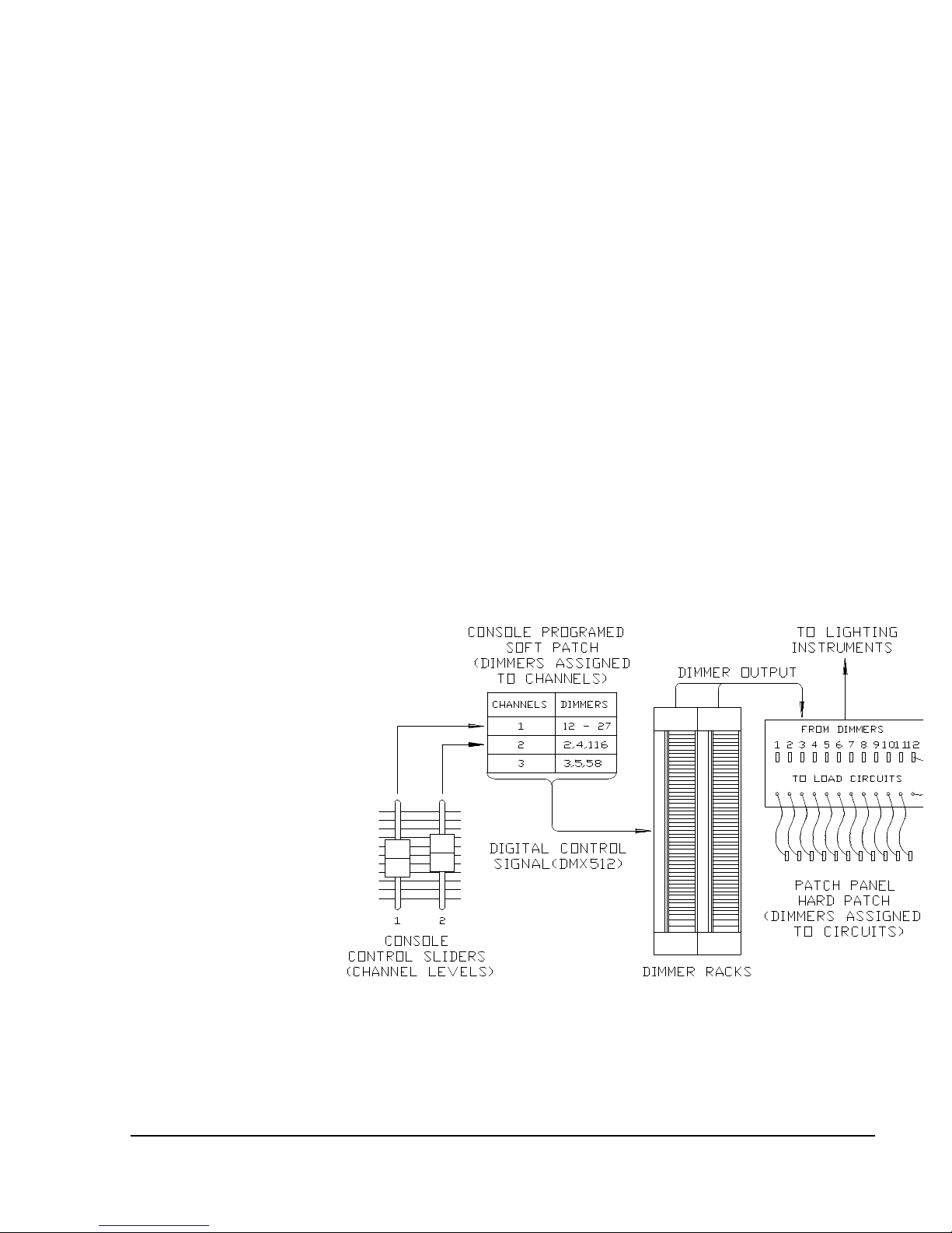
CHAPTER 5:
Setting Up the Soft Patch
What is a Soft Patch?
The term "patch" refers to a table that shows which dimmer numbers are
controlled by which control channels. The dimmers in turn feed electrical
current into the circuits that connect to lighting instruments. In some older
lighting systems, the assignments of instruments to dimmers are altered
through a "hard" patch. A hard patch is a hard-wire method such as the
"telephone patch" or a "slider patch" used to connect a circuit to a dimmer.
Older lighting consoles have each dimmer controlled by its own slider. Newer
control consoles such as the Encore series, allow you to control a number of
dimmers with one control channel (a "soft" patch). If a theater uses a hard
patch from the circuits to the dimmers, and a console with a soft patch, there
may be an association of up to three numbers for each lighting instrument: a
circuit number, a dimmer number, and a control channel number.
Figure 5.1, Lighting Control System Functional Diagram
The Patch display is a way to "patch" a control channel to a dimmer channel.
The dimmer number may be connected to an actual dimmer, or the connection
Software Version 3.05
67
Page 82

Colortran Encore Control Console
may be to an automated device such as a color scroller or a moving fixture. A
control channel may be patched to a single dimmer or multiple dimmers.
When a dimmer is currently patched to a channel and then re-patched to a new
channel, the dimmer is "robbed" from the previous assignment. The previous
channel assignment is deleted without warning and the dimmer is given to the
new channel assignment.
BASIC RULE: Remember that a dimmer can be controlled by only
?
one channel, but a channel can control any number of dimmers.
Patch Displays
The Patch display consists of two windows of four columns each: Channel,
Dimmer, Level, and Profile. Level refers to a proportional level assigned to an
individual dimmer. Profile refers to a dimmer output curve assigned to an
individual dimmer. The Patch display has two different display modes for the
patch information: the Patch: By Channel display, and the Patch: By Dimmer
display.
Press the (BY CHANL) soft key to access the Patch: By Channel display. Press
the (BY DIM) soft key to access the Patch: By Dimmer display.
Software Version 3.05
HINT: The same soft key, S1, toggles between the Patch: By
?
Channel and the Patch: By Dimmer displays.
68
Page 83
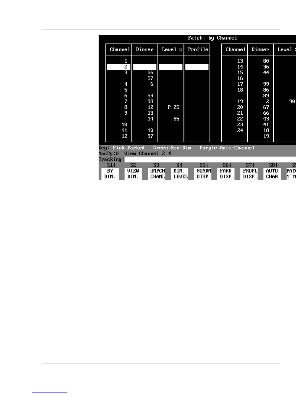
Chapter 5: Setting Up the Soft Patch
Figure 5.2, Patch: By Channel Display
Patch: By Channel Display Mode
The Patch: By Channel display lists the patches by channel order in the first
column, and the dimmer assignments in the second column. If more than one
dimmer is patched to a channel, the channel number is not repeated in the
channel column, but the channel column will always show a channel number at
the top (when the dimmer assignments to a channel continue from the previous
page).
If no dimmers are patched to a given channel, there is a blank in the dimmer
column next to the channel number. A patched channel is shown in white on
the display, and an unpatched channel is shown in gray .
Software Version 3.05
69
Page 84
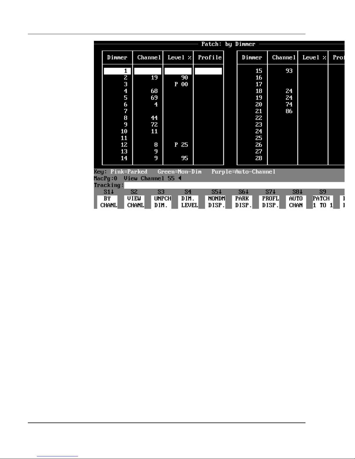
Colortran Encore Control Console
Figure 5.3, Patch: By Dimmer Display
Patch: By Dimmer Display Mode
The Patch: By Dimmer display lists the patches in dimmer order in the first
column, and the channel assignments in the second column. If a given dimmer
is not patched to a channel, there is a blank in the channel column next to the
dimmer number. The dimmers are always shown in gray on the display, unless
they are assigned as Non-Dim dimmers.
ADVANCED TOPIC: See the Non-Dim Dimmers topic in Chapter
?
20, Advanced Patching Options.
Other Patch Display Modes
There are two other Patch display modes: the Patch: Parked Dimmers
subdisplay, and the Patch: Non-Dim Dimmers subdisplay. Press the (PARK
DISP.) soft key to access the Patch: Parked Dimmers subdisplay. Press the
(NONDM DISP.) soft key to access the Patch: Non-Dim Dimmers subdisplay.
Software Version 3.05
70
Page 85

ADVANCED TOPIC: For more information on the Patch: Parked
?
Dimmers subdisplay or the Patch: Non-Dim Dimmers subdisplay, see Chapter
20, Advanced Patching Options.
Chapter 5: Setting Up the Soft Patch
Patching Channels to Dimmers
In the Patch: By Channel display, you begin a patch command by pressing the
number of the channel that you want to assign, followed by the [@] key. At
this point, you can enter dimmer number assignment(s). The console
automatically inserts the word "Dimmer" into the Command Line when you
enter the first number after the [@] key. To assign more than one dimmer,
enter a dimmer list, which can contain a range of dimmers joined with the [+],
[-], and [>] keys. Execute the command by pressing the [ENTER] key.
? EXAMPLE: To patch channel 2 to dimmer 51 in the Patch display:
[2] [@] [51] [ENTER]
If you want to construct patching commands using the dimmer number(s) first,
use the [DIMMER] key to start the patching command.
? EXAMPLE: To patch dimmers 7 and 24 to channel 2 in the Patch
display:
[DIMMER] [7] [+] [24] [@] [2] [ENTER]
BASIC RULE: In all patching commands, it is not necessary to
?
specify channel numbers or dimmer numbers with a channel or dimmer key;
the console automatically assumes that the channel is addressed in the first
part of the command and the dimmer in the second part, unless the [DIMMER]
key is used.
You can also patch ranges of channels to ranges of dimmers in a single
command. This is called range patching. Range patching commands require
that you specify consecutive ranges of dimmers and channels with the Thru [>]
key. The quantity of channels and dimmers must also be the same. This
feature can save you a considerable amount of time if you are patching large
groups of dimmers that are offset from their corresponding channel numbers.
? EXAMPLE: To patch channels 1 through 12 to dimmers 13
through 24 in a single command:
[1] [>] [12] [@] [13] [>] [24] [ENTER]
- or -
Software Version 3.05
71
Page 86

Colortran Encore Control Console
[DIMMER] [13] [>] [24] [@] [1] [>] [12] [ENTER]
BASIC RULE: You must specify the same quantity of consecutive
?
dimmers and consecutive channels in range patching commands.
Unpatching Channels and Dimmers
Unpatching a channel or dimmer means eliminating any patching assignments
associated with it. When you unpatch a channel, all dimmers patched to the
channel are unpatched. When you unpatch a dimmer, its association with the
channel is eliminated, but all other dimmers that are patched to the channel
remain patched to it. All special attributes of dimmers and channels remain
intact when they are unpatched (i.e., dimmer profiles, dimmer proportional
levels, Non-Dim dimmer status, Automated Channel status, etc.).
ADVANCED TOPICS: For more information on dimmer and
?
channel special attributes, see Chapter 20, Advanced Patching Options.
To perform unpatching, you use the (UNPCH CHANL) or (UNPCH DIM.) soft
keys, found in the Patch: By Channel and Patch: By Dimmer displays,
respectively. To unpatch a channel you must be in the Patch: By Channel
display, and to unpatch an individual dimmer you must be in the Patch: By
Dimmer display.
? EXAMPLE: To unpatch channel 2 through 7 in the Patch: By
Channel display:
(UNPCH CHANL) [2] [>] [7] [ENTER]
? EXAMPLE: To unpatch dimmers 7 and 24 in the Patch: By Dimmer
display:
(UNPCH DIM.) [7] [+] [24] [ENTER]
Default Dimmer or Channel
In both Patch: By Dimmer and Patch: By Channel displays, one line of the
patch is highlighted in reverse video. This indicates the default dimmer or
channel for entering commands. If a command is begun using the [@] key, the
console automatically inserts the default dimmer or channel prior to the "@" in
Software Version 3.05
72
Page 87

Chapter 5: Setting Up the Soft Patch
the Command Line. The default channel (or dimmer) is the channel (or
dimmer) that was affected by the last patch command.
Software Version 3.05
73
Page 88

Colortran Encore Control Console
? EXAMPLE: If the current default in the Patch: By Channel
display is channel 15, pressing the @ key would cause the following to appear
on the Command Line:
"Channel 15 @" (The console is now waiting for you to provide a
dimmer
number list. You do not need to use the [DIMMER] key - the console is
expecting a dimmer number at this point.)
? EXAMPLE: To patch the default channel to a dimmer list in the
Patch: By Channel display:
[@] [# list] [ENTER]
? EXAMPLE: To unpatch the default channel in the Patch: By Channel
display:
(UNPCH CHANL) [ENTER]
? EXAMPLE: To patch the default dimmer to channel 2 in the Patch:
By Dimmer display:
[@] [2] [ENTER]
? EXAMPLE: To unpatch the default dimmer in the Patch: By Dimmer
display:
(UNPCH DIM.) [ENTER]
Patch 1 To 1
Software Version 3.05
Use the (PATCH 1 TO 1) soft key in both the Patch: By Dimmer and Patch: By
Channel displays to patch each control channel to the dimmer of the same
number (i.e. channel 1 at dimmer 1, channel 2 at dimmer 2, etc.). This is the
default setting for the patch table. The (PATCH 1 TO 1) soft key is available in
the Patch display to return the patch to a one to one channel/dimmer
assignment. Parked dimmers, Non-Dim dimmers, proportional dimmer levels,
and profiles are retained when you execute this command. The console
prompts you to confirm the Patch 1 To 1 command with a second press of the
[ENTER] key before the command is executed.
? EXAMPLE: To establish a 1 to 1 patch in the Patch display:
1. (PATCH 1 TO 1) [ENTER] ("OVERWRITE WARNING”
confirmation request appears.)
2. [ENTER] (Executes the command.)
74
Page 89

ADVANCED TOPICS: See Chapter 20, Advanced Patching Options.
?
Chapter 5: Setting Up the Soft Patch
Automated Channels
You can designate any channels as Automated channels in the Patch display.
Automated channels are not affected by the Grandmaster fader, the Blackout
switch, or submaster Bump buttons in Solo mode. Use Automated channels to
control automated equipment such as color scrollers and moving lights.
ADVANCED TOPICS: For more information on Automated
?
channels, see Chapter 20, Advanced Patching Options.
Software Version 3.05
75
Page 90

Page 91

CHAPTER 6:
Setting Channel Levels
Two-Scene Preset Mode*
*(Encore models 24/48, and 48/96 only
Does not apply to models XL or XL/2.)
When you have the operating mode switch set to TWO-SCENE, the first thing
that you will notice is that the crossfader LEDs now indicate the position of the
crossfaders. Each crossfader controls the output of one scene, X or Y. The left
crossfader controls Scene X so that when the crossfader is at the top of its
travel, scene X is "at full." The right crossfader controls Scene Y so that when
the crossfader is at the bottom of its travel, Scene Y is at full (backwards to
crossfader X). When both crossfaders are moved together, the look on stage
fades from the contents of one scene to the other scene. By having separate
crossfaders, you can fade one scene in before the other fades out, or vice-versa.
This type of crossfader is called a "Split Crossfader".
When in Two-Scene mode, you cannot affect live channel levels on stage with
the keypad. The only levels that will appear on stage are those that originate
from the channel faders or from submasters. When you are working in any of
the "blind" displays (Submaster, Group, or Effect), you can edit channel levels
only with the keypad. (This is different from Multi-Scene mode.)
BASIC RULE: In Two-Scene Preset mode, the channel fader
?
positions always determine the stage output levels. If you move channel faders
while you are working in a blind display, it will affect live levels on stage.
Channel Faders vs. Keypad in MultiScene Mode*
*(Encore models
24/48, and 48/96 only.
Does not apply to models XL or XL/2.)
In Multi-Scene mode, you can use the keypad or the channel faders to enter,
record and edit the levels in console memory, and play the cue back later with
the GO button. This is one difference between the Two-Scene Preset mode and
the Multi-Scene (memory) mode of operation.
In Two-Scene Preset mode, the channel faders always control live stage levels.
You cannot use the channel faders to edit any blind displays. When you are
Software Version 3.05
77
Page 92

Colortran Encore Control Console
working in Multi-Scene mode, you can control channel levels in any display
with either the channel faders or the keypad. If you want to use a channel fader
to control a channel level that has been set by the keypad or by a cue, you must
first move the channel fader to match the current level of the channel in the
display. As soon as the level is matched, the channel level changes color to
indicate that the fader now has control. This is referred to as “match and
grab” operation. You can set the level anytime with the keypad, but the fader
must always match and grab if it is not set at the channel’s current level.
When you change between different displays, the level for a given channel may
be shown in the new display at a different level than is indicated by the fader
position. You must match and grab the channel with the channel fader to
control the level with the channel fader in this display. Once you have matched
and grabbed in the new display, you must match and grab again in any
previously selected display in order to control the channel there with the fader.
BASIC RULE: The following actions can cause the channel faders
?
to temporarily lose control over their
channels when you are working in Multi-Scene mode
? Setting levels with the keypad
? Executing cues with the GO button
? Using a fader to control the channel level in a different
display
You must match and grab in order to regain fader control over these
channels
The channel faders affect channels differently depending on the current display.
In "live" displays (Stage and Playback), the channel faders affect live levels on
stage. In "blind" displays (Preview, Group, Submaster, Playback and
Tracksheet), channel faders control the channel levels, but only within that
display, not on stage. You can edit channels in these "blind" displays using
both the channel faders or the keypad.
? EXAMPLE: To set a submaster "blind" with the channel faders:
1. [SUB] (Use the [SUB] display key, not
the [SUB] data entry key.)
2. (SEL SUB) [#]
3. Move channel faders to establish desired levels.
HINT: In the example above, when you select a different submaster,
?
the previous sub remembers the levels set by the channel faders.
HINT: If you edit a submaster blind while it is active, the edits show
?
on stage as you make them.
Software Version 3.05
78
Page 93
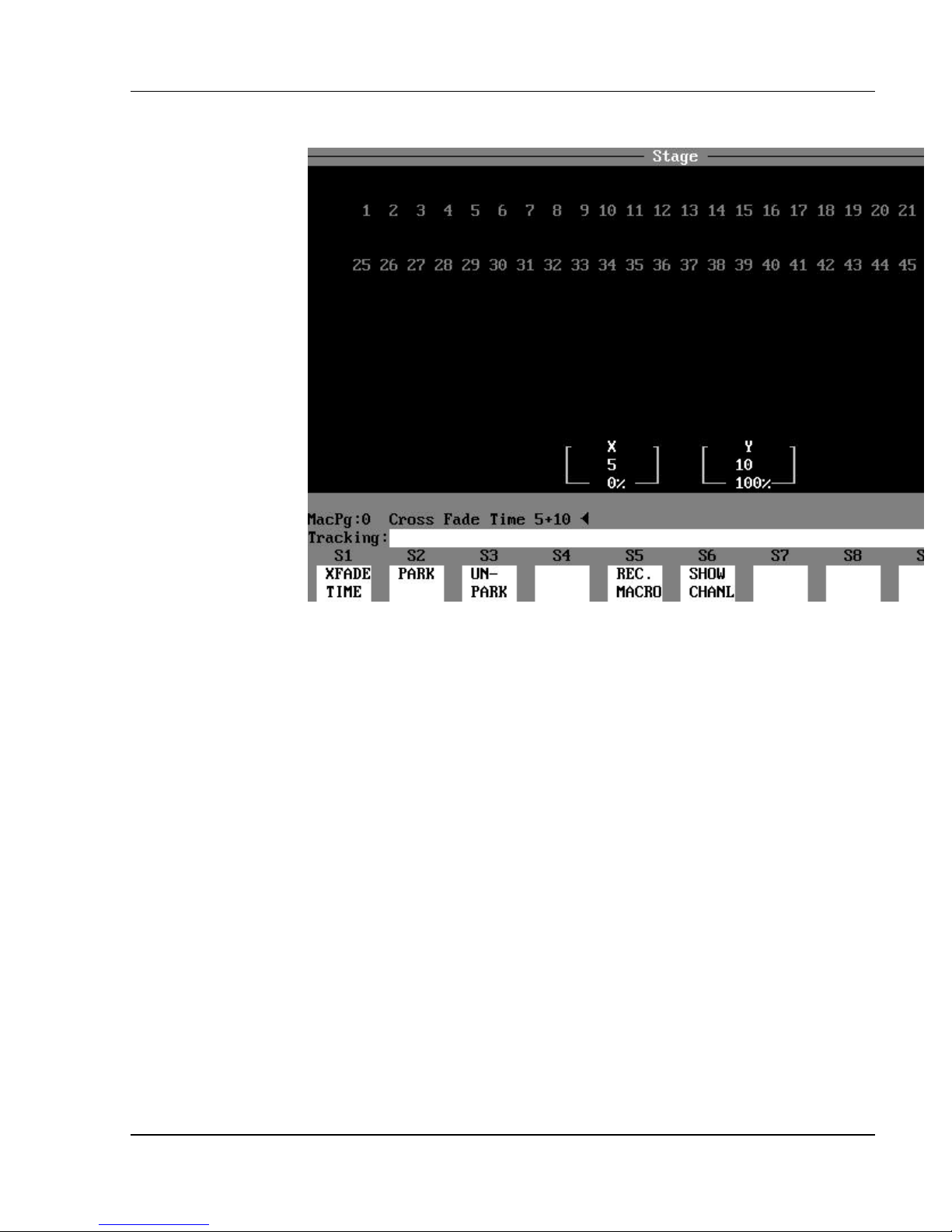
Chapter 6: Setting Channel Levels
Figure 6.1, Cross Fader Boxes
Crossfader Time*
*(Encore models 24/48, and 48/96 only.
Does not apply to models XL or XL/2.)
The crossfade time is the time it takes for the fade to occur when the crossfader
handle is moved to the end of its travel. The relative crossfader levels (%)
appear in two boxes in the lower part of the display (see Figure 6.1). The
crossfade time (seconds) for the respective crossfaders is also shown in the
boxes. The time can be set differently for each crossfader using the (XFADE
TIME) soft key. You can also control the crossfade time manually.
? EXAMPLE: To set a crossfade time of 5 seconds on the X fader, and
10 seconds on the Y fader:
(XFADE TIME) [5] [+] [10] [ENTER]
? EXAMPLE: To set the crossfaders for a manual crossfade:
(XFADE TIME) [0] [+] [0] [ENTER]
- or -
(XFADE TIME) [ENTER]
Software Version 3.05
79
Page 94

Colortran Encore Control Console
Keypad Commands
In the Multi-Scene mode, channel levels are entered and recorded through the
Command Line by using the Data Entry Keypad. When a number is entered
into the Command Line, the console automatically assumes by default that
channels are being addressed (there is no channel key). The [DIMMER] key is
available to directly control individual dimmers, and for use in patching
commands.
BASIC RULE: There is no “channel” key; when you enter a number
?
in the Command Line by pressing the key, the console automatically assumes
that the number is a channel number.
? EXAMPLE: To set channel 2 to a level of 75%:
[2] [@] [75] [ENTER] (“Channels 2 @ 75%” appears in
the Command Line.)
Channel Lists
Software Version 3.05
ADVANCED TOPICS: See the Dimmer Check topic in Chapter 12,
?
Utilities, Warnings, Printing, And Default Settings.
You do not need to enter a zero when you specify a level that is a multiple of
ten. If you enter [5], the console assumes you mean 50%; if you enter [8], the
console assumes you mean 80%; etc.
? EXAMPLE: To set channel 2 to a level of 70%:
[2] [@] [7] [ENTER] ("Channels 2 @ 70% " appears in
the Command Line.)
You can use the AND [+], THRU [>], and MINUS [-] keys to make lists of
channels and other items. You are not required to enter the list in any
particular order. You can generally just enter channel lists in the order in
which you might be thinking of them.
? EXAMPLE: If you enter key strokes as follows:
[12] [>] [24] [+] [36] [-] [23] [>] [13] [@] [FULL] [ENTER]
"Channels 12 > 24 + 36 - 23 > 13 @ Full" appears in the Command Line.
Since only channels 12, 24, and 36 are set to Full level by the command, it
would have been easier to enter:
80
Page 95

Chapter 6: Setting Channel Levels
[12] [+] [24] [+] [36] [@] [FULL] [ENTER]
HINT: Items using the [THRU] key may be listed from lowest to
?
highest, or highest to lowest.
? EXAMPLE: The basic channel and level Command Line syntax in
any channel/level display:
[#] [@] [#] [ENTER] ("Channels # @ # "
appears in the Command Line.)
? EXAMPLE: Listed below are common examples of channel/level
command variations:
[#] [@] [#] [ENTER] (Sets single channel to a level.)
[#] [+] [#] [@] [#] [ENTER] (Sets 2 different channels to same level).
[#] [>] [#] [@] [#] [ENTER] (Sets a list of consecutive channels to same level.)
[#] [>] [#] [-] [#] [@] [#] [ENTER] (Sets a list of consecutive channels minus a single
channel to the same level.)
Captured Channels
The term "captured channels" refers to channels with levels that are currently
being set. Captured channel levels are shown in reverse video in the display.
When a level setting command is entered in the Command Line, the channels
listed in the command are "captured." All captured channels are under direct
control of the wheel (see the next topic, Wheel). When levels are captured, any
command that begins with [@] will affect the currently captured channels.
? EXAMPLE: To set channels 6 - 9 at 100%, then reset at 65%:
1. [6] [>] [9] [@] [FULL] [ENTER] (Channels 6 - 9
set at 100%, remain captured.)
2. [@] [65] [ENTER] (Channels 6 - 9
set at 65%, remain captured.)
3. Press the [CLEAR] key to release the captured channels.
BASIC RULE: The [CLEAR] key releases captured channels, but
?
the Command Line must be “empty”, or else the [CLEAR] key acts like a
“backspace” key to clear keystrokes from the Command Line.
Software Version 3.05
81
Page 96
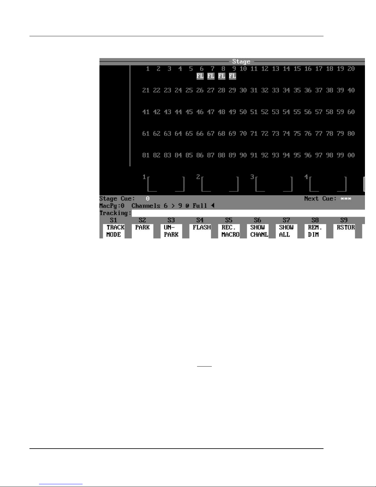
Colortran Encore Control Console
Figure 6.2, Captured Channels
You do not need to set channels to a level in a command to capture them. They
can be captured by simply listing them and pressing [ENTER].
? EXAMPLE: To capture a single channel, without setting a level:
[#] [ENTER]
? EXAMPLE: To capture channels 5 - 20 and channel 30, without
setting a level:
[5] [>] [20] [+] [30] [ENTER]
When the Command Line is “empty” and no channels are currently captured,
pressing the [ENTER] key captures all active channels (all non-zero channels).
The exception to this is that pressing [ENTER] does not capture any Automated
channels. Automated channels must be addressed specifically.
ADVANCED TOPIC: See the Automated Channels topic in Chapter
?
20, Advanced Patching Options.
Software Version 3.05
82
Page 97

Chapter 6: Setting Channel Levels
? EXAMPLE: To capture all active channels (channels reading above
zero):
[ENTER] (All channels reading above zero are now
captured on the wheel.)
BASIC RULE: All captured channels are unaffected by executed
?
cues; pressing the GO button does not affect them, even if the channels have
new level assignments in the new cue. Captured channels remain under active
control of the wheel until control is released by pressing the [CLEAR] key.
BASIC RULE EXCEPTION: The exception to the rule above is
when the [GO TO CUE] key is used in the Tracksheet or Preview displays.
ADVANCED TOPICS: See Chapter 9, Playing Back Cues.
?
Wheel Control
The wheel is used to adjust the levels of individual or multiple channels
proportionally up or down. Whenever any channels are captured, their levels
are adjustable on the wheel.
? EXAMPLE: To set channels to 50%, and then use wheel control to
adjust the level in the Stage, Preview, Group, Submaster and Tracksheet
displays:
[# list] [@] [50] [ENTER] (Channel list now active
on the wheel, even if the
level specified is zero.)
? EXAMPLE: To capture channels at their active levels in the
Stage, Preview, Group, Submaster and Tracksheet displays:
[# list] [ENTER] (Channels in list now
captured and controlled by the
wheel.)
? NOTE: If you find that the tracking color of certain channels is not
appropriate to the display, you may have moved the wheel accidentally while
channels were captured. There is a possibility of the wheel moving so slightly
that the movement is noted internally without changing the channel level in the
display. If you find that the tracking color has changed, it may be prudent to
confirm that levels are still tracking by checking the Tracksheet display.
Software Version 3.05
83
Page 98

Colortran Encore Control Console
ADVANCED TOPICS: See Chapter 10, Editing Cues And Using
?
Track Modes.
Proportional Control with the Wheel
All captured channels are affected proportionally when you use the wheel.
Proportional control operates such that a given rotation of the wheel may cause
a greater change to a higher level than to a lower level. For example, if a
channel is captured at 10% and the wheel spins 1/2 a rotation, the level may
increase to 20% (10 points). If the same channel is captured at 40%, and the
wheel spins 1/2 a rotation, it may increase the level to 80% (40 points).
? EXAMPLE: Channel 1 is at 25%, and channel 2 is at 50%.
Channels 1 and 2 are both then captured and thus "captured on the wheel." If
the wheel is used to move channel 1 to 50%, channel 2 will be brought to full.
If the wheel is moved further, channel 1 will increase until it reaches full also.
This is known as "overranging". As the wheel is used to lower the levels,
channel 1 will start to come down from full first. When it reaches 50%,
channel 2 will begin to come down. Eventually you can return all channels
under control of the wheel to their original levels, provided that you maintain
wheel control over them.
Because you can control levels proportionally with the wheel, you can increase
the intensity of a lighting look on stage without changing the feel of the look or
the mix of the colors. And because of the ability to overrange with the wheel,
you have the opportunity to "run all channels up to full" and still be able to
return to your original look.
The wheel also responds to movements based upon the speed with which the
movements are made. A 1/4 rotation made slowly may raise a level by 20
points, while the same rotation made rapidly might raise the level by 50 points.
The wheel is said to have "ballistics". This helps the wheel to have a better
"feel" and to respond more quickly to your movements.
Restoring Channel Levels (“Undo”)
You can use the (RSTOR) soft key command to return channel levels to their
level prior to the last level setting command. The (RSTOR) soft key is
available in the Stage, Preview, Group, Submaster and Tracksheet displays.
Although the previous level command may not be present in the Command
Line history, it remains available to the Restore command.
Channels may be selectively restored by entering a list of channels which are to
remain at their current level.
Software Version 3.05
84
Page 99

Chapter 6: Setting Channel Levels
? EXAMPLE: To restore channel levels from the Stage, Preview,
Group, Submaster and Tracksheet displays:
(RSTOR) [ENTER] (Restores all channels.)
- or -
(RSTOR) [# list] [ENTER] (Restores only the
channels in list.)
Using the (RSTOR) soft key repeatedly toggles between the last two consecutive
levels that a channel has been assigned.
? EXAMPLE: To toggle a channel's last two assigned levels in the
Stage, Preview, Group, Submaster or Tracksheet displays:
1. [# list] [@] [#] [ENTER]
2. [RSTOR] [ENTER] (Displays channel levels
set before last level setting
command.)
3. (RSTOR) [ENTER] (Toggles back to the new
levels set by the last
command.)
In the Stage display, the Restore command always restores channels to the
levels assigned just prior to the last changes that you made. You can switch to
another display, edit channel levels, return to the Stage display, and still use the
Restore command to return to the previous stage levels.
The Restore command remembers the last level changes you made in an editing
display (Preview, Group, Submaster, or Tracksheet). Once you edit in another
‘blind” display, the Restore command memory is active only for that display (as
well as in Stage display).
Remainder Dim Command
Use the Remainder Dim (REM. DIM) soft key to make all channels, except
those specified in the command, go to a level of 0%. The (REM. DIM) soft key
is available in the Stage, Preview, Group, Submaster and Tracksheet displays.
The command syntax allows you to list the channels that you want to stay at
their current levels, and thereby force the remainder of the channels to dim to
zero.
? EXAMPLE: To dim all channels except a specified list of
channels, in the Stage, Preview, Group, Submaster and Tracksheet displays:
[# list] (REM. DIM) [ENTER]
Software Version 3.05
85
Page 100

Colortran Encore Control Console
HINT: In the Example above, pressing the (RSTOR) key will restore
?
channels to their previous settings.
You can specify a new level for a channel list when you use the Remainder Dim
command.
? EXAMPLE: To specify a level of 50% for a channel list and take all
other channels to zero:
[# list] [@] [50] (REM. DIM) [ENTER]
Software Version 3.05
86
 Loading...