

Page 1
Step 2: Terminate the wiring to the appropriate termi-
nals on your low voltage switch as is required for your
application. See the tables on page 5-7.
Step 3: When all wires have been terminated, gently
stuff the wires back into the junction box in the wall.
W i r i n g a n d I n s t a l l a t i o n
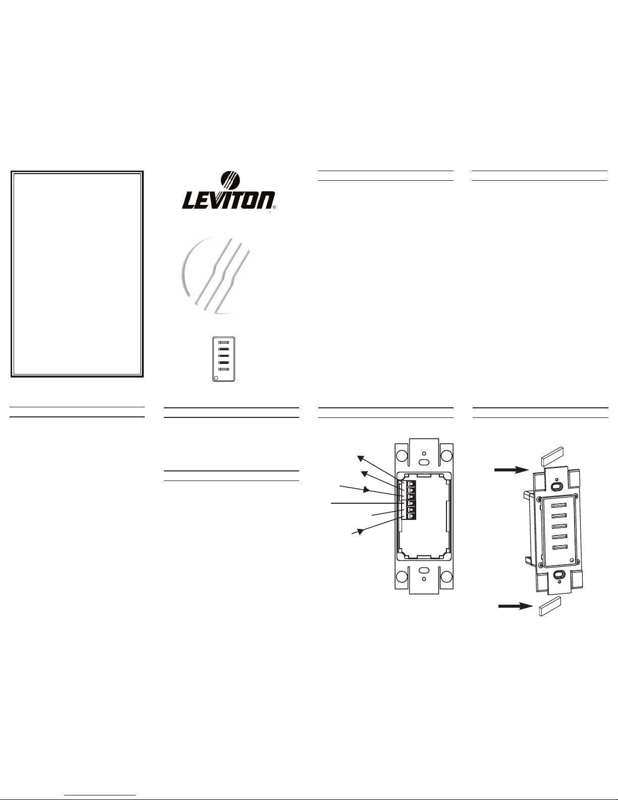
Step 1: If using a Decora Plus screwless wall plate,
remove the center tabs from the device as shown in
the following figure:
Limited Warranty
LEVITON LIGHTING CONTROL DIVISION of Leviton
Manufacturing Co Inc. warrants its Dimmer Systems and
Controls to be free of material and workmanship defects
for a period of two years after system acceptance or 26
months after shipment, whichever comes first. The Z-MAX
Relay cards are covered for a period of Ten (10) years.
Lighting fixtures manufactured by Leviton are covered for a
period of one year. This Warranty is limited to repair or
replacement of defective equipment returned Freight Pre-
Paid to Leviton Lighting Control Division at 20497 SW
Teton Ave., Tualatin, Oregon 97062, USA. User shall call
1-800-959-6004 and request a return authorization number
to mark on the outside of the returning carton, to assure
that the returned material will be properly received at
Leviton. All equipment shipped back to Leviton must be
carefully and properly packed to avoid shipping damage.
Replacements or repaired equipment will be returned to
sender freight prepaid, F.O.B. factory. Leviton is not
responsible for removing or replacing equipment on the job
site, and will not honor charges for such work. Leviton will
not be responsible for any loss of use time or subsequent
damages should any of the equipment fail during the war-
ranty period, but agrees only to repair or replace defective
equipment returned to its plant in Tualatin, Oregon. This
Warranty is void on any product that has been improperly
installed, overloaded, short circuited, abused, or altered in
any manner. Neither the seller nor Leviton shall be liable
for any injury, loss or damage, direct or consequential aris-
ing out of the use of or inability to use the equipment. This
Warranty does not cover lamps, ballasts, and other equip-
ment which is supplied or warranted directly to the user by
their manufacturer. Leviton makes no warranty as to the
Fitness for Purpose or other implied Warranties.
For Technical Assistance Call:
1-800-959-6004
www.colortran.com
www.leviton.com
I n t r o d u c t i o n
1
2
The Low Voltage Switches are a variant on the tradition-
al low voltage switch. They provide a switched momen-
tary contact which closes a low voltage circuit when the
switch is depressed and provides optional feedback to
the user through an LED contained within each button.
Additionally, each station has a rear illuminated "locator"
LED in the lower left hand corner.
All standard precautions for wiring traditional low volt-
age control devices apply:
1. The cable should not pass near any source of elec-
trical noise or interface such as fluorescent circuits or
motor wiring.
2. Close proximity to any AC wiring should be avoided
3. All analog wiring shall be in it's own conduit.
4. Any wire type capable of carrying the required volt-
age and current may be used
5. Observe standard voltage drop calculations to
ensure that no less than +10 volts are received by the
station Less than +10V and the LED's will not be
bright enough to be seen or if voltage is quite low, may
not light at all.
P r e c a u t i o n s a n d R e q u i r e m e n t s
Low Voltage
Switches
Zone 2
Zone 1
LED Locator
Switches with
LED Indicator
Zone 7
Zone 6
Zone 4
Zone 5
Zone 6
Zone 2
Zone 3
Zone 1
Zone 5
Zone 3
Zone 4
Zone 1
Zone 2
Zone 4
Zone 3
Zone 8
Zone 2
Zone 1 Zone 5
Zone 5 Zone 10
Zone 6
Zone 7
Zone 8
Zone 9Zone 4
Zone 3
Zone 2
Zone 1
ØØLVS-Ø6W
Zone 3
Zone 2
ØØLVS-Ø2W
ØØLVS-Ø8W
ØØLVS-Ø1W
ØØLVS-Ø3W
ØØLVS-Ø5W
ØØLVS-Ø4W
ØØLVS-1ØW
ON/OFF
Zone 2
Zone 1
Zone 3
Zone 2
Zone 1
Zone 4
Zone 1
LIT-32712-00 Rev A
8/16/2004
Step 2: Terminate the wiring to the appropriate termi-
nals on your low voltage switch as is required for your
application. See the tables on page 5-7.
Step 3: When all wires have been terminated, gently
stuff the wires back into the junction box in the wall.
W i r i n g a n d I n s t a l l a t i o n
Step 1: If using a Decora Plus screwless wall plate,
remove the center tabs from the device as shown in
the following figure:
This page left intentionally blank.
This page left intentionally blank.
10
6
Step 2: Terminate the wiring to the appropriate termi-
nals on your low voltage switch as is required for your
application. See the tables on page 5-7.
Step 3: When all wires have been terminated, gently
stuff the wires back into the junction box in the wall.
W i r i n g a n d I n s t a l l a t i o n
Step 1: If using a Decora Plus screwless wall plate,
remove the center tabs from the device as shown in
the following figure:
This page left intentionally blank.
This page left intentionally blank.
10
5
Wiring and Installation
Precautions and Requirements Description
Terminal Connection Types
Installation Requirements
Electrical Requirements
As this is an analog system, any system topology is
allowed.
The “LOC”ator LED is illuminated when it is
connected to +24VDC.
The LV200 lighting controller is a Decora-style
device for controlling non-dimmable and dimmable
luminaires connected to the miniZ Intelligent Daylight
Management System and Z-MAX Relay System. The
LV200 provides a unique control station with multifunction operational and programming capabilities in a
5-button configuration. The device come in white with
a matching wallplate.
Input Voltage: 24Vdc
Input Current: 24mA
Environmental
Operating Temperature Range:
0 degrees C to 55 degrees C
Relative Humidity:
20% to 90% non-condensing
Step 2: Terminate the wiring to the appropriate termi-
nals on your low voltage switch as is required for your
application. See the tables on page 5-7.
Step 3: When all wires have been terminated, gently
stuff the wires back into the junction box in the wall.
W i r i n g a n d I n s t a l l a t i o n
Step 1: If using a Decora Plus screwless wall plate,
remove the center tabs from the device as shown in
the following figure:
This page left intentionally blank.
This page left intentionally blank.
10
4
LV200
Control Station
LV200
ON
OFF
+24V
PILOT
COMMON
LOCATION
+V to minZ ON
+V to miniZ OFF
+24Vdc
Common only if LED
feedback is desired
+V, when +V
Location LED
illuminates
Pilot
LV200
Function description:
Push On - all lights to daylight harvesting level
Push Max - all lights to maximum trim level
Hold Bright - raise light levels with press hold or
multiple press
Hold Dim - lower light levels with press hold or
multiple press
Push Dim - lower light levels with press hold or
multiple press
Push Off - turn off lights
Programming capabilities:
Set daylighting target level
Set minimum lighting level
3
All standard precautions for wiring traditional low
voltage control devices apply:
1. The cable should not pass near any source of
electrical noise or interface such as fluorescent
circuits or motor wiring.
2. Close proximity to any AC wiring should be
avoided.
3. All analog low voltage wiring shall be in it’s own
conduit.
4. Any wire type capable of carrying the required
voltage and current may be used.
5. Observe standard voltage drop calculations to
ensure that no less than +10 volts are received by the
station. Less than +10 and the LEDs will not be bright
enough to be seen or if voltage is quite low, may not
light at all.
1
2
Limited Warranty
LEVITON LIGHTING MANAGEMENT SYSTEMS
DIVISION of Leviton Manufacturing Co Inc. warrants its
Dimmer Systems and Controls to be free of material and
workmanship defects for a period of two years after system
acceptance or 26 months after shipment, whichever comes
first. The Z-MAX Relay cards are covered for a period of Ten
(10) years. Lighting fixtures manufactured by Leviton are
covered for a period of one year. This Warranty is limited
to repair or replacement of defective equipment returned
Freight Pre-Paid to Leviton Lighting Management Systems
Division at 20497 SW Teton Ave., Tualatin, Oregon 97062,
USA. User shall call 1-800-959-6004 and request a return
authorization number to mark on the outside of the returning
carton, to assure that the returned material will be properly
received at Leviton. All equipment shipped back to Leviton
must be carefully and properly packed to avoid shipping
damage. Replacements or repaired equipment will be
returned to sender freight prepaid, F.O.B. factory. Leviton
is not responsible for removing or replacing equipment
on the job site, and will not honor charges for such work.
Leviton will not be responsible for any loss of use time or
subsequent damages should any of the equipment fail
during the warranty period, but agrees only to repair or
replace defective equipment returned to its plant in Tualatin,
Oregon. This Warranty is void on any product that has been
improperly installed, overloaded, short circuited, abused, or
altered in any manner. Neither the seller nor Leviton shall be
liable for any injury, loss or damage, direct or consequential,
arising out of the use of or inability to use the equipment.
This Warranty does not cover lamps, ballasts, and other
equipment which is supplied or warranted directly to the user
by their manufacturer. Leviton makes no warranty as to the
Fitness to Purpose or other implied Warranties.
DI-000-LV200-00A
Rev. A 8/2005
Page 2
Step 2: Terminate the wiring to the appropriate termi-
nals on your low voltage switch as is required for your
application. See the tables on page 5-7.
Step 3: When all wires have been terminated, gently
stuff the wires back into the junction box in the wall.
W i r i n g a n d I n s t a l l a t i o n
Step 1: If using a Decora Plus screwless wall plate,
remove the center tabs from the device as shown in
the following figure:
This page left intentionally blank.
This page left intentionally blank.
10
Step 2: Terminate the wiring to the appropriate termi-
nals on your low voltage switch as is required for your
application. See the tables on page 5-7.
Step 3: When all wires have been terminated, gently
stuff the wires back into the junction box in the wall.
W i r i n g a n d I n s t a l l a t i o n
Step 1: If using a Decora Plus screwless wall plate,
remove the center tabs from the device as shown in
the following figure:
This page left intentionally blank.
This page left intentionally blank.
10
Step 2: Terminate the wiring to the appropriate termi-
nals on your low voltage switch as is required for your
application. See the tables on page 5-7.
Step 3: When all wires have been terminated, gently
stuff the wires back into the junction box in the wall.
W i r i n g a n d I n s t a l l a t i o n
Step 1: If using a Decora Plus screwless wall plate,
remove the center tabs from the device as shown in
the following figure:
This page left intentionally blank.
This page left intentionally blank.
10
9
Step 2: Terminate the wiring to the appropriate termi-
nals on your low voltage switch as is required for your
application. See the tables on page 5-7.
Step 3: When all wires have been terminated, gently
stuff the wires back into the junction box in the wall.
W i r i n g a n d I n s t a l l a t i o n
Step 1: If using a Decora Plus screwless wall plate,
remove the center tabs from the device as shown in
the following figure:
This page left intentionally blank.
This page left intentionally blank.
10
10
7
Step 2: Terminate the wiring to the appropriate termi-
nals on your low voltage switch as is required for your
application. See the tables on page 5-7.
Step 3: When all wires have been terminated, gently
stuff the wires back into the junction box in the wall.
W i r i n g a n d I n s t a l l a t i o n
Step 1: If using a Decora Plus screwless wall plate,
remove the center tabs from the device as shown in
the following figure:
This page left intentionally blank.
This page left intentionally blank.
10
8
Step 2: Terminate the wiring to the appropriate termi-
nals on your low voltage switch as is required for your
application. See the tables on page 5-7.
Step 3: When all wires have been terminated, gently
stuff the wires back into the junction box in the wall.
W i r i n g a n d I n s t a l l a t i o n
Step 1: If using a Decora Plus screwless wall plate,
remove the center tabs from the device as shown in
the following figure:
This page left intentionally blank.
This page left intentionally blank.
10
Step 2: Terminate the wiring to the appropriate termi-
nals on your low voltage switch as is required for your
application. See the tables on page 5-7.
Step 3: When all wires have been terminated, gently
stuff the wires back into the junction box in the wall.
This page left intentionally blank.
10
Step 2: Terminate the wiring to the appropriate terminals on your low voltage switch as is required for your
application. See the tables on page 5-7.
Step 3: When all wires have been terminated, gently
stuff the wires back into the junction box in the wall.
Wiring and Installation
See the table on page 5.
Step 2: Terminate the wiring to the appropriate termi-
nals on your low voltage switch as is required for your
application. See the tables on page 5-7.
Step 3: When all wires have been terminated, gently
stuff the wires back into the junction box in the wall.
W i r i n g a n d I n s t a l l a t i o n
T e r m i n a l C o n n e c t i o n T y p e s
Step 1: If using a Decora Plus screwless wall plate,
remove the center tabs from the device as shown in
the following figure:
8 9
This page left intentionally blank.
All System Programming, individual switch configuration,
and other device configuration options is performed at
the device to which your switch is connected.
P r o g r a m m i n g / O p e r a t i o n
This page left intentionally blank.
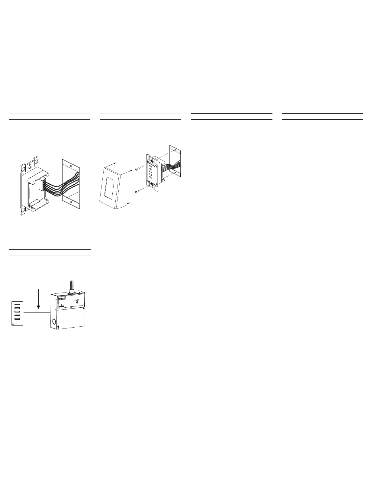
Step 4: Securely mount the station to the wall using the
provided screws.
Step 5: Mount the wall plate to the station.
10
7
Part #
Total #
Buttons
Button
Label
Station
Terminal
00LVS-08W 8
Zone 1 SW1/LD1
Zone 2 SW2/LD2
Zone 3 SW3/LD3
Zone 4 SW4/LD4
Zone 5 SW6/LD6
Zone 6 SW7/LD7
Zone 7 SW8/LD8
Zone 8 SW9/LD9
00LVS-10W 10
Zone 1 SW1/LD1
Zone 2 SW2/LD2
Zone 3 SW3/LD3
Zone 4 SW4/LD4
Zone 5 SW5/LD5
Zone 6 SW6/LD6
Zone 7 SW7/LD7
Zone 8 SW8/LD8
Zone 9 SW9/LD9
Zone 10 SW10/LD10
Station
Terminal
(00LVS-05W)
Function
Wiring
Method #1
Wiring
Method #2
SW_ Switch Output +24VDC COMMON
LD_ LED Input COMMON +24VDC
LOC Locator COMMON +24VDC
+24V/CM Reference +24VDC COMMON
Depending on the needs of your equipment, the low volt-
age switch will support either closed circuit connection to
common, or closed circuit +V. The chart below lists the
options and requirements for the LD, LOC, and +24V/CM
terminals.
The terminals will accept 14-24 GA wire.
Wiring and Installation
Step 2: Terminate the wiring to the appropriate termi-
nals on your low voltage switch as is required for your
application. See the tables on page 5-7.
Step 3: When all wires have been terminated, gently
stuff the wires back into the junction box in the wall.
W i r i n g a n d I n s t a l l a t i o n
T e r m i n a l C o n n e c t i o n T y p e s
Step 1: If using a Decora Plus screwless wall plate,
remove the center tabs from the device as shown in
the following figure:
8 9
This page left intentionally blank.
All System Programming, individual switch configuration,
and other device configuration options is performed at
the device to which your switch is connected.
P r o g r a m m i n g / O p e r a t i o n
This page left intentionally blank.
10
Station
Terminal
(00LVS-05W)
Function
Wiring
Method #1
Wiring
Method #2
SW_ Switch Output +24VDC COMMON
LD_ LED Input COMMON +24VDC
LOC Locator COMMON +24VDC
+24V/CM Reference +24VDC COMMON
Depending on the needs of your equipment, the low volt-
age switch will support either closed circuit connection to
common, or closed circuit +V. The chart below lists the
options and requirements for the LD, LOC, and +24V/CM
terminals.
The terminals will accept 14-24 GA wire.
Programming / Operation
To activate programming mode, press and hold the
MAX button (On and Off outputs at +24v) for seven
(7) seconds. At this point the ON and OFF LEDs will
flash alternately, each on for 0.25 seconds.
To program the daylight photocell target level, tap the
ON button. The ON and OFF LEDs will now blink
alternately, with the ON LED lit for 0.375 seconds and
the OFF lit for 0.125 seconds.
Use the BRIGHT and DIM buttons to increase and
decrease the lights (0-10 volt outputs). Adjustment
will be in the range of 1 to 10 volts.
Tapping the MAX button will save your changes and
re-enter programming mode with the ON and OFF
LEDs flashing alternately, each on for 0.25 seconds.
To program the “Min” level, tap the OFF button. The
ON and OFF LEDs will now blink alternately, with
the OFF LED lit for 0.375 seconds and the ON lit for
0.125 seconds.
Use the BRIGHT and DIM buttons to increase and
decrease the lights (0-10 volt outputs). Adjustment
shall be in the range of 0 to 4 volts.
Tapping the MAX button will cause the Min level to
be saved and re-enter programming mode with the
ON and OFF LEDs flashing alternately, each on for
0.25 seconds.
To exit the programming mode, tap the MAX button.
If no button is pressed for longer than two (2)
minutes, the programming mode will automatically
cease.
Programming / Operation
LV200
Typical One-Line Diagram
1211 13 14
(5) Analog low
voltage wires
 Loading...