

Page 1

LEO™
LEO™ LED Fresnel
Cat. No. LFD10
User’s Guide
© 2015 Leviton Mfg. Co., Inc.
DI-000-LFD10-05A
Page 2

Page 3

W ARNINGS AND CAUTIONS
• TO AVOID FIRE SHOCK OR DEATH; TURN OFF POWER at circuit breaker or fuse and test that
power is off before installation.
• TO AVOID SERIOUS PERSONAL INJURY, always connect this product to a grounded circuit.
• To be installed and/or used in accordance with electrical codes and regulations.
• If you are unsure about any part of these instructions, consult an electrician.
SAFETY NOTES
WARNING: TO AVOID DEATH, SERIOUS PERSONAL INJURY OR PROPERTY DAMAGE:
• Do not open the housing or attempt any repairs. In the unlikely event the unit may require service
please contact Leviton Technical Support. Opening the housing or attempting to repair product will
void the warranty.
• Do not expose this product to rain or moisture. This product is for indoor use only! (IP20) When
transferring product from extreme temperature environments, (e.g., cold truck to warm humid
ballroom) condensation may form on the internal electronics of the product. To avoid causing a
failure, allow product to fully acclimate to the surrounding environment before connecting it to power.
• Do not operate this product if you see damage on the housing, lenses, or cables.
CATALOG LOGIC
LFD10-30B; LFD10-50B
Fixture Wattage Color Temperature Housing
LFD: LED Fresnel 10: 100W -30: 3200K B: Black Housing
-50: 5600K
SPECIFICATIONS
CAT. NO. LFD10
WATTAGE 100W
STANDBY LOAD
BEAM ANGLE 11° - 53°
WEIGHT 12.1 lbs. (5.5 kg)
SIZE W 10.1" (257mm) x H 15.2" (385mm) x D 14.6" (370mm)
ELECTRICAL 100-240 VAC, 50/60Hz
P1
Page 4

GETTING STARTED
Thank you for choosing LEO™ LED Fresnel by Leviton®. Every LEO™ LED Fresnel has been thoroughly
tested and has been shipped in perfect operating condition. Your LEO™ LED Fresnel should include:
• Fixture
®
• powerCON
• Fuse, glass tube, 3A (for 110V)
• Fuse, glass tube, 1.5A (for 220V)
• Metal Color Frame 7.5" x 7.5" (190 x 190mm)
• Safety Guard 7.5" x 7.5" (190 x 190mm)
• Safety Cable, 31.5" (800mm) with Spring Clips
• User’s Guide
• 36"-39.5" (1m) power lead with powerCON
B connector
®
& PBG NEMA 5-15P Connector
Power cords with alternate connectors, and powerCON
®
extension cables are available.
Please contact Leviton and review product data sheets for details.
Important: Unpack the product and check the box to make sure all the parts are in the package and
are in good condition. If any of them are damaged, please contact the shipper to make a claim. If any
components are missing, please contact our Customer Service Department at 1-800-736-6682.
P2
Page 5

PRODUCT INTRODUCTION
LEO™ LED Fresnel is a high-performance Fresnel-style LED lighting fixture that delivers a beautiful flat
even field of light in a choice of color temperatures (3200K and 5600K) with high color rendering index
(CRI 90+). The fixture is fully dimmable from 0% to 100% and can be controlled manually or via DMX
®
controller. It also supports power linking with built-in powerCON
connectors. Virtually quiet operation
makes it ideal for use in any situation. The fixture is RDM-ready for precise monitoring of the LED chip’s
performance and status to make maintenance easy.
IDENTIFY THE PARTS
Barn door
clip
Lens clips
Status
indication
lamps
4-Digit display
3 Operation
buttons
Reset button
Manual
dimming knob
Control panel
12 mm Hole
mounting yoke
Back panel Handle
& loop out
Fresnel
Lens
3-Slot
accesory
runners
Front View
Barndoor clip
Power in
Fuse
Power switch
DMX input
(XLR5-pin male)
DMX output
(XLR5-pin female)
Focusing Knob
Rear View
P3
Page 6

SAFETY NOTES
• This product contains no user-serviceable parts. Do not open the housing or attempt any repairs,
doing so will void the manufactures warranty . In the unlikely event the unit may require service please
contact Leviton technical support.
• Do not operate this product if you see damage on the housing, lenses, or cables.
• This product is for indoor use only! (IP20) To prevent risk of fire or shock, do not expose this product to
rain or moisture. When transferring product from extreme temperature environments, (e.g. cold truck
to warm humid ballroom) condensation may form on the internal electronics of the product. To avoid
causing a failure, allow product to fully acclimate to the surrounding environment before connecting
it to power.
REPLACE FUSE
CAUTION:
Fuse pre-installed in BLACK fuse cover supports 220V AC Power only.
Fuse pre-installed in GREY fuse cover supports 110V AC Power only.
Always make sure you are connecting this product to the proper voltage in accordance
with the specifications in this manual or on the product’s specification label.
Choose the correct fuse for your power voltage before connecting power.
Step 1: Unplug the product from power.
Step 2: Use a slotted screwdriver, push slightly and rotate counterclockwise to open the fuse cap.
Step 3: Take out the fuse cap and fuse. Put a new fuse inside the fuse cap.
Step 4: Screw the fuse cap back in place and reconnect power.
FUSE 110V/3A; 220V/1.5A
SLOW BLOW
OPEN LOCK
P4
Page 7

CONNECT POWER
DMX IN LOOP
XLR-5 signal ports
CAUTION:
WARNING: T O AVOID SERIOUS PERSONAL INJUR Y, always connect this product to
a grounded circuit.
®
LEO™ LED Fresnel comes with a power lead terminated with a powerCON
and a PBG NEMA 5-15P connector on the other side. Other connector options are available from Leviton
or may be installed by your contractor. In addition, the fixture is designed for "Feed-Thru" operation using
single power source connection at the first fixture, then, using powerCON
®
The maximum load supported is 16A through the powerCON
connectors which is reduced to 15A if you
use a 15A source power connector like a NEMA 5-15P.
A connector on one side,
®
extensions between fixtures.
If creating your own powerCON
®
connectors, use the table below to wire the included powerCON
®
B connector, or a local plug to the power lead.
Connection Wire
AC Live Brown
AC Neutral Blue
AC Ground Green / Y ellow
CONNECT DMX
LEO™ LED Fresnel uses 5-pin XLR connectors for signal transmission and can be controlled via
DMX-512 protocol. The diagram below shows the fixture’s XLR-5 signal ports.
XLR Pin # Signal
1 common
1
5
1
432
5
234
2 data 3 data +
4 NC
5 NC
Step 1: Connect the (male) 5-pin connector side of the DMX cable to the output (female) 5-pin connector
of the DMX console.
Step 2: Connect the end of the cable coming from the console which will have a (female) 5-pin connector
to the fixture’s input port ("DMX IN") consisting of a (male) 5-pin connector.
Step 3: Then, proceed to connect from the output port ("LOOP") as stated above to the input of the
following fixture and so on.
P5
Page 8
MOUNT FIXTURE
CAUTION:
Always mount this product in a safe position with adequate ventilation and away from
a heat source, at least 20" (50 cm) from adjacent surface, and no flammable materials
close by the product while it is operating, at least 8" (20 cm) from adjacent surfaces.
Always connect the provided Safety Cable to the fixture and a suitable anchor. The safety
cable should loop through the fixture yoke and be connected to a secure attachment at
the other end.
LEO™ LED Fresnel may be mounted in any position (max. tilting +45° to -90° from horizontal); however,
make sure there is adequate room for ventilation, configuration, and maintenance.
The fixture comes with a hanging/mounting yoke to which you can attach mounting clamps. The bracket
has a 0.5" (12mm) hole, which is appropriate for this purpose. Make sure the clamps are capable of
supporting the weight of this product.
FIXTURE ANGLE ADJUSTMENT
The fixture can be tilted up and down to position the light where it is needed.
Step 1:
Step 2: With the fixture turned on, use the handle to tilt it to the desired angle.
Step 3: Tighten the yoke fastening knob.
Loosen the yoke fastening knob, use the handle on the rear of the unit to keep the fixture steady.
FIELD ANGLE ADJUSTMENT
You can adjust the field angle of the fixture with the focusing knob on the rear of the unit.
To reduce the field angle (SPOT), turn the focus dial clockwise.
To enlarge the field angle (FLOOD), turn the focus dial counterclockwise.
P6
Page 9
ACCESSORIES
LEO™ LED Fresnel can accommodate many different accessories.
Cat. No. Description Part Number
All Safety Cable (included) TA0SC-000
LFD10 8 Leaf Barn Door 7.5" x 7.5" (190 x 190mm) LFD10-BDB
LFD10 Metal Color Frame 7.5" x 7.5" (190 x 190mm) (included) LFD10-CFB
LFD10 Safety Guard 7.5" x 7.5" (190 x 190mm) (included) LFD10-SGB
ACCESSORY SLOTS
CAUTION:
Accessories such as barn doors and color scrollers must be secured by a safety cable
to the mounting structure.
Make sure all color / diffusion media are locked in position with the barn door clip before
hanging the fixture.
LEO™ LED Fresnel has 3 accessory slots in the front of the fixture and is equipped with a spring-loaded
barn door clip that prevents color frames and accessories from falling out.
Step 1: Release the barn door clip by pushing it sideways while gently pulling backwards
Step 2: Insert the media/accessories, secure with a safety cable where necessary.
Step 3: Lock the barn door clip by pushing sideways while gently pushing forward.
P7
Page 10
OPERATION
CAUTION:
Do not touch this product’s housing during operation because it may be very hot if
overheated.
The maximum ambient temperature is 95˚F (35˚C). Do not operate this product at a
higher temperature.
Do not cover the ventilation holes when operating to avoid internal overheating.
Avoid direct eye exposure to the light source while the product is on.
In case of a serious operating problem, stop using this product immediately!
LEO™ LED Fresnel will start a self-checking process when power is applied. The unit will display the
DMX address for dimming when ready to use. For standard operation, connect the fixture to a power
source (100~240V AC single phase), and a DMX signal cable. The LED Display will turn on after the
power switch is turned to "ON" position. You are now ready to set the desired configuration and DMX
addresses.
You can assign a DMX channel to control dimming, cooling fan speed, LED display-on time, built-in
effects and live/safe modes according to the DMX value on the "Menu Map". These parameters can also
be assigned through a console.
CONTROL INTERFACE
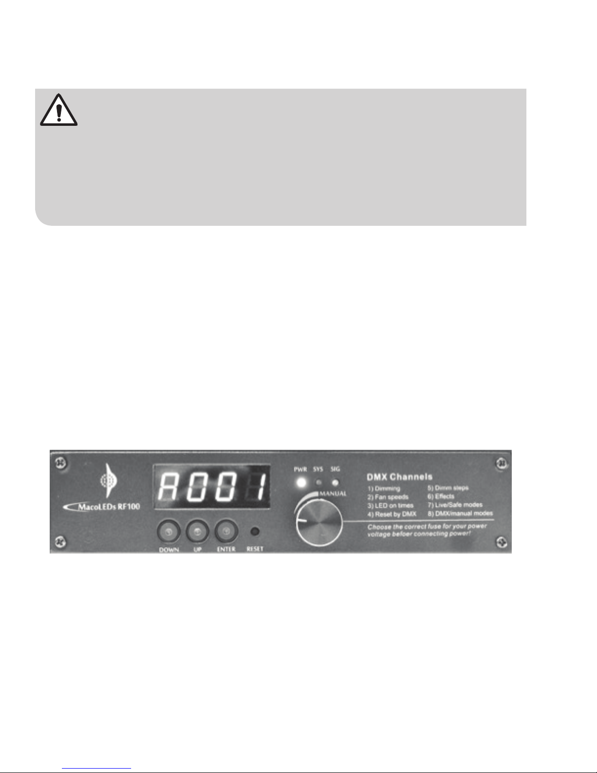
The fixture comes with a 4-digit Display and 3 operation buttons on the side of the unit for control
settings:
OPERATION BUTTONS
DOWN Backward / downward change / query sequence change
UP Forward / upward change / query sequence change
ENTER Confirm / mode switch / enter new data or setting
RESET Press to reset the fixture, parameters remain unchanged
P8
Page 11
STATUS INDICATION LAMPS
PWR (Power) Light up when power is applied to the unit.
SYS (System) Indicates the status of the fixture:
No lights when working properly,
Flashes when the fixture light source detects overheating.
SIG (Signal) Light up when proper DMX signal is received,
Flashes when receiving wrong signals,
No lights when no signal is received.
CONTROL BASICS
CAUTION:
Connect power to the powerCON
switch to "ON" position. The 4-digit display will turn on and the fixture is ready to operate. The fixture is
defaulted for DMX control; press the 3 operation buttons to the desired operation mode.
Check the fuse before connecting power.
®
connector at the rear side of LEO™ LED Fresnel and switch the power
DIMMING DMX CHANNEL
The fixture can be controlled by a DMX channel, displayed by the 4-Digit display . The light output intensity
is based on the DMX channel value.
Note: LEO LED Fresnel requires only one DMX channel for dimming, and that is the minimum number of
DMX channels needed for the fixture.
SHOWING DIMMING VALUE
The dimming value is displayed on the display for local monitoring.
MONITORING LED TEMPERATURE
Temperature of the LED light source is displayed.
P9
Page 12
CONTROLLING COOLING FAN SPEED
The highest cooling fan speed can be remotely or locally controlled. The LFD10 is defaulted so that the
fan will start to operate in slowest speed when LED temperature is detected at 95°F (35°C) or above to
maintain the lowest fan noise.
(Note: cooling fan cannot be stopped; slowest speed is 60% of full speed)
4-DIGIT DISPLAY ON
The light-on time of the 4-Digit display can be set to 30 sec., 1 min., 2 min., 3 min. or continuously on.
RESETTING THE FIXTURE
The fixture can be reset locally by pressing the RESET button on the unit or remotely by a DMX channel.
SETTING DIMMING STEPS
Two dimming steps, standard and fine, are available for selection. It can be selected locally or remotely.
PRE-LOADED EFFECTS
The fixture has pre-loaded eight effects for demonstration. It can be selected locally or remotely.
DIMMING MODES
Two dimming modes, DMX and manual control, are available for selection. It can be selected locally or
remotely.
SETTING SAFE OPERATION MODE
CAUTION:
"Live" mode allows the LED light source to operate at over-temp conditions which might
shorten the lifetime and even burn out the LED chip!
It is recommended to use the factory default "Safe" mode for normal operations.
At Safe mode, LEO™ LED Fresnel will limit the light output when the LED temperature rises above 149°F
(65°C) in order to protect the LED light source from overheating. The light output will be the first priority
when Live Mode is selected.
P10
Page 13
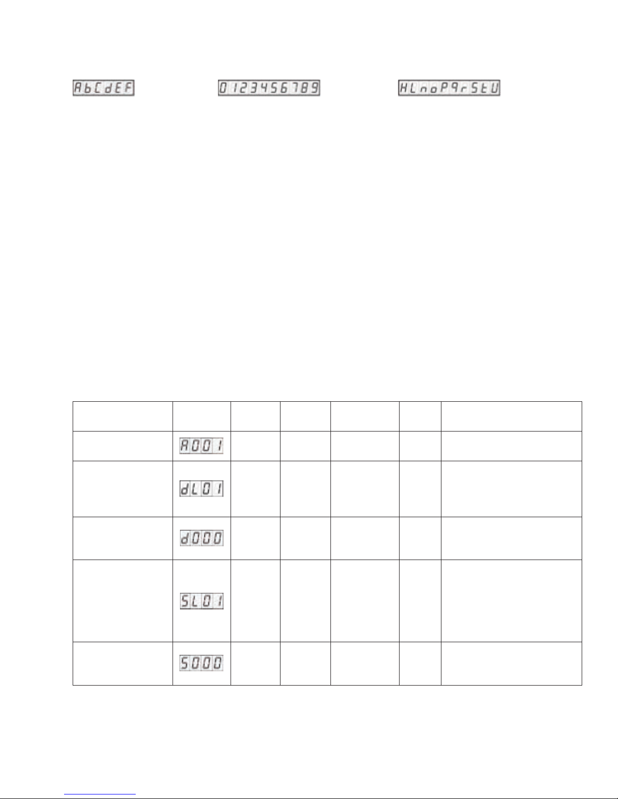
NUMBERS & CHARACTERS DISPLAYED
A,B,C,D,E,F NUMBER 0-9 H,L,N,O,P,Q,R,S,T,U
Note: The corresponding display number "5" and character "S" appear the same, please note the difference.
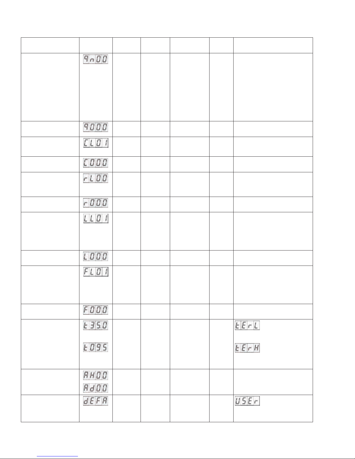
CONTROL ATTRIBUTES AND DEF AULT DISPLA YS AND SETTINGS
The LEO™ LED Fresnel fixtures have several different control attributes. With the exception of the
dimming attribute which must be assigned a DMX value for remote control, all other attributes may be
manually set only at the fixtures, or, remote controlled from your DMX console. Therefore, from a DMX
perspective, your fixture may be a 1, 2, 3, 4, 5, 6, 7 or 8 channel fixture depending on which attributes are
assigned to a channel. Some customers will assign a unique DMX address for each dimming attribute,
then, a common channel for all other attributes so fixtures are always controlled together. The system is
flexible so the specific configuration is up to you.
The fixture is factory-set to display the default DMX address "A001" until a new address is assigned.
Then, the last assigned DMX address will become the default display.
Please refer to the chart below to see all the default settings and displays:
CONTROL ATTRIBUTES
Menu Items Default
Display
Dimming address
Dimming mode
Dimming mode
control address
Operation mode
Operation mode
control address
Value
Range
1-512 1 0-255 Mandatory to assign DMX
1/2 1 1
1-512 0 0-255
0/1 1 0-127
1-512 0 0-255
Default
Value
Options
DMX Value
128-255
Level Remarks
2
0
1
channel to this attribute
Dimming according to
DMX value
Dimming according to
manual knob
Live: Light output will be
the first priority
Safe: LED over-temp
protection, light output will
be limited when temp. over
149°F (65°C)
P11
Page 14
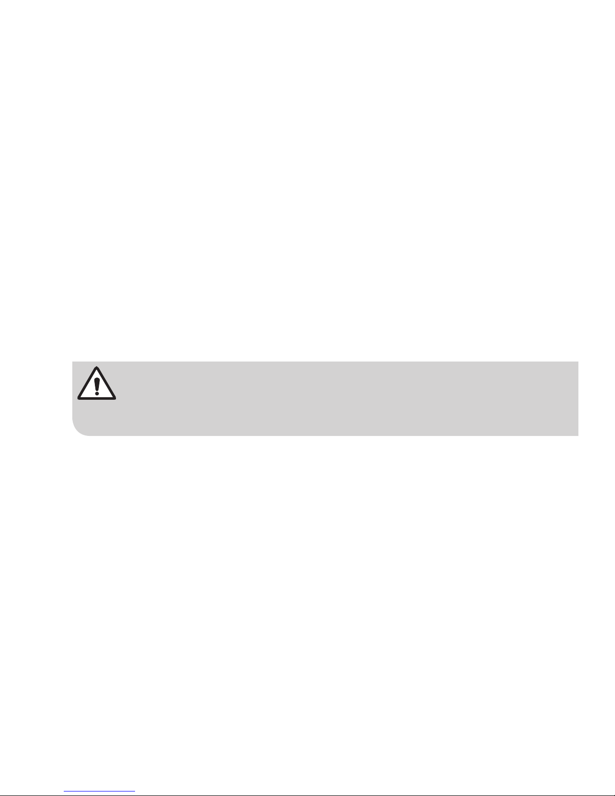
DEFAULT SETTINGS
Menu Items Default
Display
Built-in effects
Built-in effects
control address
Dimming steps
Dimming steps
control address
Remote DMX reset
Remote DMX reset
control address
LED display-on
time
LED display-on time
control address
Fan speed
Fan speed
control address
LED temperature ˚C
Value
Range
0~8 0 0-20
1-512 0 0-255
1/2 1 0-31
1-512 0
0/1 0 0-127
1-512 0
1~5 1 0-50
1-512 0 0-255
1~5 1 0-50
1-512 0 0-255
0/1 0
Default
Value
Options
DMX Value
21-40
41-70
71-100
101-130
131-160
161-190
191-220
221-255
32-255
128-255
51-100
101-150
151-200
201-255
51-100
101-150
151-200
201-255
Level Remarks
0
Normal dimming
1
Flash effect 1 – super fast
2
Flash effect 2 – fast
3
Flash effect 3 – medium
4
Flash effect 4 – slow
5
Fade-in & fade-out effect 1
6
Fade-in & fade-out effect 2
7
Fade-in & fade-out effect 3
8
Fade-in & fade-out effect 4
1
Standard: 256 steps
2
Fine: 512 steps
0
At normal control
1
Trigger reset
Continuously on
1
LED display off after 30 seconds
2
LED display off after 1 minute
3
LED display off after 2 minutes
4
LED display off after 3 minutes
5
Auto
1
90% of full speed
2
80% of full speed
3
70% of full speed
4
60% of full speed
5
Error: Below the
lowest limit < 32°F / 0.1°C
˚F
Dimming Value
Parameter
setting status
0~255 0 0-255 Display in hex
P12
Error: Above
the highest limit > 212°F /
99.9°C
Press "ENTER"
button for 5 seconds to
resume default settings.
Page 15
MAINTENANCE
T o eliminate unnecessary wear and improve its lifespan, during periods of non-use completely disconnect
the product from power via breaker or by unplugging it.
EXPECTED LED LIFESPAN
LEDs gradually decline in brightness over time, mostly because of heat. Packaged in clusters, LEDs
exhibit higher operating temperatures than in ideal, single-LED conditions. For this reason, using
clustered LEDs at their fullest intensity significantly reduces the LED's lifespan. Under normal conditions,
this lifespan can be 50,000 hours at 77 °F (25 °C). If extending this lifespan is vital, lower the operating
temperature by improving the ventilation around the product and reducing the ambient temperature to an
optimal operating range. In addition, limiting the overall projection intensity may also help to extend the
LED's lifespan.
LENS
The lens in your fixture is made of a high quality glass and reflective coating which should require little
maintenance. However, due to fog residue, smoke and dust, lens cleaning must be carried out periodically
to optimize light output. To maintain optimum performance and minimize wear, clean this product at least
twice a month. However, usage and environmental conditions contribute to increased cleaning frequency .
CAUTION:
Do not use ammonia-based or other harsh commercial cleaners. They may damage the
glass surface and the Anti-Reflective coatings.
Step 1: Unplug the product from power and wait until the product is at room temperature.
Step 2: Remove dust with a blast of oil-free air or wipe with a clean, lint-free cloth. Isopropyl alcohol
Step 3: Make sure to dry all parts completely before plugging the product back in.
Replace lenses if they contain visible damage (cracks or deep scratches).
may be used on the cloth.
P13
Page 16

TRADEMARK DISCLAIMER
Use herein of third party trademarks, service marks, trade names, brand names and/or product names
are for informational purposes only, are/may be the trademarks of their respective owners; such use is
not meant to imply affiliation, sponsorship, or endorsement.
FOR CANADA ONLY
For warranty information and/or product returns, residents of Canada should contact Leviton in writing at
Leviton Manufacturing of Canada Ltd to the attention of the Quality Assurance Department, 165 Hymus
Blvd, Pointe-Claire (Quebec), Canada H9R 1E9 or by telephone at 1 800 405-5320.
WARRANTY INFORMATION
LEVITON LIGHTING & ENERGY SOLUTIONS DIVISION of Leviton manufacturing Co. Inc. warrants its
Entertainment Products to be free of material and workmanship defects for a period of two years after
system acceptance or 26 months after shipment, whichever comes first. This Warranty is limited to repair
or replacement of defective equipment returned Freight Pre-Paid to Leviton Lighting & Energy Solutions
Division at 20497 Teton Ave., Tualatin, Oregon 97062, USA. User shall call 1-800-959-6004 and request
a return authorization number to mark on the outside of the returning carton, to assure that the returned
material will be properly received at Leviton. All equipment shipped back to Leviton must be carefully
and properly packed to avoid shipping damage. Replacements or repaired equipment will be returned to
sender freight prepaid, F.O.B. factory. Leviton is not responsible for removing or replacing equipment on
the job site, and will not honor charges for such work. Leviton will not be responsible for any loss of use
time or subsequent damages should any of the equipment fail during the warranty period, but agrees only
to repair or replace defective equipment returned to its plant in Tualatin, Oregon. This warranty is void
on any product that has been improperly installed, overloaded, short circuited, abused, or altered in any
manner. Neither the seller nor Leviton shall be liable for any injury, loss or damage, direct or consequential
arising out of the use of or inability to use the equipment. This Warranty does not cover lamps, ballasts,
and other equipment which is supplied or warranted directly to the user by their manufacturer. Leviton
makes no warranty as to the Fitness for Purpose or other implied Warranties.
P14
Leo is a registered trademark of Leviton Mfg. Co., Inc. in the U.S.A.:
Page 17

NOTES
__________________________________________________________________________________
__________________________________________________________________________________
__________________________________________________________________________________
__________________________________________________________________________________
__________________________________________________________________________________
__________________________________________________________________________________
__________________________________________________________________________________
__________________________________________________________________________________
__________________________________________________________________________________
__________________________________________________________________________________
__________________________________________________________________________________
__________________________________________________________________________________
__________________________________________________________________________________
__________________________________________________________________________________
__________________________________________________________________________________
__________________________________________________________________________________
__________________________________________________________________________________
__________________________________________________________________________________
__________________________________________________________________________________
__________________________________________________________________________________
__________________________________________________________________________________
__________________________________________________________________________________
__________________________________________________________________________________
__________________________________________________________________________________
__________________________________________________________________________________
P15
Page 18

NOTES
__________________________________________________________________________________
__________________________________________________________________________________
__________________________________________________________________________________
__________________________________________________________________________________
__________________________________________________________________________________
__________________________________________________________________________________
__________________________________________________________________________________
__________________________________________________________________________________
__________________________________________________________________________________
__________________________________________________________________________________
__________________________________________________________________________________
__________________________________________________________________________________
__________________________________________________________________________________
__________________________________________________________________________________
__________________________________________________________________________________
__________________________________________________________________________________
__________________________________________________________________________________
__________________________________________________________________________________
__________________________________________________________________________________
__________________________________________________________________________________
__________________________________________________________________________________
__________________________________________________________________________________
__________________________________________________________________________________
__________________________________________________________________________________
__________________________________________________________________________________
P16
Page 19

Page 20

LEO™
LEVITON MANUFACTURING CO., INC.
LIGHTING & ENERGY SOLUTIONS DIVISION
20497 SW Teton Avenue. Tualatin, OR 97062
Telephone: 1-800-736-6682 FAX: 503-404-559
Tech Line (6:00 AM-4:00 PM P.S.T. Monday-Friday): 1-800-959-6004
Email: [email protected]
Leviton Manufacturing Co., Inc.
201 North Service Road, Melville, N.Y. 11747
Telephone: 1-800-323-8920 • FAX: 1-800-832-9538
Information and specifications are subject to change without notice.
DISCARD ANY OLDER VERSIONS OF THIS USER’S GUIDE AND REPLACE WITH THIS VERSION.
Visit Leviton’s Web site at http://www.leviton.com
© 2015 Leviton Manufacturing Co., Inc. All Rights Reserved
© 2015 Leviton Mfg. Co., Inc.
DI-000-LFD10-05A
Page 21
ARTWORK PRINT SPECIFICATIONS
FINAL
11
8.5"
Part No.
PART NUMBER REV DESCRIPTION
DI-000-LFD10-05A
SPECIFICATIONS :
Thickness:
Material:
Finish:
For manuals - designates cover specifications
40 Lb.
:
Colors: over
Black
1:
2:
3:
4:
Die Line Key:
Die Cut
1
Fold Line
1
Perforate
MANUAL INTERIORS / BINDERY / FOLD SCHEME :
Body Material:
Thickness:
Bindery
Die cut
Perfect Bind
X
PROCESS :
Fold
Drill
Saddle Stitch
Trim
Colors: over
Black
1:
2:
3:
4:
1
1
DIMENSIONS / FOLD SCHEME / BINDERY DIAGRAM
Installation Manual
Spot
X
CMYK
Kiss Cut
Spot
X
CMYK
Fonts:
Helvetica
1:
2:
3:
4:
Cellophane
Fonts:
1:
2:
3:
4:
Glue
Offset Flexo
X
Other
Line Screen:
Angle:
Resolution:
Die Cut Punch/Drill Hole
"
Fold Line
COMMENTS :
The information in this document is the exclusive PROPRIETARY property of LEVITON MANUFACTURING COMPANY, INC. It is disclosed
with the understanding that acceptance or review by the recipient constitues an undertaking by the recipient. (1) to hold this information in strict
confidence, and (2) not to disclose, duplicate, copy, modify or use the information for any purpose other than that for which disclosed.
FOR LEVITON USE ONLY
PlantApprovals:
X
Mktg Eng
Cust Other
X
Artist:
LE0181-4886
P. Clapp
Notes:
PN-ARN: Pilot Rev:ECR Number:
90
J. Tang
MacoStar
X
X
Released Artwork Format:
S. Muthu
V. LoNigro
Production PDF
PMCQA
X
X
X
Artwork Release Date:
D. Buerer
S & A
S. Muthu
Other
G. Molaro
Artwork Print Specification Sheet Rev A11.eps
12/15/15
 Loading...