

Page 1
10/100Mbps 4-Port Internet Gateway
DESCRIPTION
Leviton’s 10/100Mbps 4-Port Internet Gateway allows multiple users to utilize a single,
secure, high-speed broadband (DSL and cable) Internet connection and creates a private
network for home, small office or school environments.
Chapters
1: Introduction
2: Hardware Installation
3: Configuration
4: Specifications
5. Appendix
A Division of Leviton Manufacturing Co.,Inc.
Technical Support: 800-824-3005
Fax: (425) 483-5270
www.levitonvoicedata.com
1
IMPORTANT INSTRUCTIONS
1. Read and understand all instructions. Follow all warnings and instructions marked on the
product.
2. Do not use this product near water—e.g., near a tub, wash basin, kitchen sink or laundry
tub, in a wet basement, or near a swimming pool.
3. Never push objects of any kind into this product through openings, as they may touch
dangerous voltages.
4. SAVE THESE INSTRUCTIONS.
SAFETY INFORMATION
1. Never install communications wiring or components during a lightning storm.
2. Never install communications components in wet locations unless the components are
designed specifically for use in wet locations.
3. Never touch uninsulated wires or terminals unless the wiring has been disconnected at the
network interface.
4. Use caution when installing or modifying communications wiring or components.
Page 2

Environmental Specifications
Dimensions: 2.5˝H x 6.5W˝ x 3.27˝D
Power: 12VDC@1000mA
Emissions: FCC ClassB
Operating Temperature: 0°C to 50°C (32°F to 122°F)
Storage Temperature: -40°C to 70°C (-40°F to 158°F)
Operating Humidity: 20% to 95% relative humidity, non-condensing
Storage Humidity: 20% to 95% relative humidity, non-condensing
Cable Specifications
Ethernet Type Cable Requirements Maximum Length
10BASE-T Category 3 or better, UTP or STP 328 ft (100M)
100BASE-TX Category 5 or better, UTP or STP 328 ft (100M)
1000BASE-T Category 5e or better, UTP or STP 328 ft (100M)
NOTE: Do not use telephone cables. Telephone cables do not support Ethernet or Fast Ethernet.
APPENDIX
A: About Static and Dynamic IP Address
A static IP address is an IP address that is assigned to a computer by an Internet service provider to be
its permanent address on the Internet. It is normally used in the computer networks, where computers
are connected all the times. As the Internet gets more crowded, there are not enough IP numbers to go
around. For this reason, more and more ISPs are offering dynamic IP address instead. Check with your
ISP if they provide you a Static IP address. A dynamic IP address is a temperately IP address assigned by
a DHCP (Dynamic Host Configuration Protocol) server from a pool of IP addresses. A dynamic IP address
may change every time when you log in the network.
INSTALLATION
1: INTRODUCTION
As the interface between WAN and LAN, the Gateway provides a secure solution for Internet access over
a shared netowrk in a home or small office environment. With the built-in NAT technology, the Gateway
delivers firewall protection, preventing network intruders and hackers. Compliant with IEEE 802.3, IEEE
802.3u standards and designed as a DHCP server, the Gateway offers high-speed network connectivity ,
providing up to 253 users access through one Internet connection and the ability to assign IP addresses
to the devices on your LAN.
Designed with a management utility, the Gateway can block specific interior users’ Internet access and
offer the network administrator remote access capabilities.
Features
· Supports PPPoE, PPTP Client, and Dynamic DNS
· Connects to a cable/DSL modem or to an Ethernet backbone
· Includes with a 4-port 10/100 Mbps Switch
· Creates a firewall to protect your computers from outside intruders
· Acts as either a DHCP server on the LAN or a DHCP client on the WAN
· Configurable through any networked PC’s web browser
· Users will be able to access the internal IP servers via the Internet, using the virtual server feature.
· Administrators can block specific interior users’ Internet access
Package Contents
· One 10/100Mbps 4-Port Internet Gateway
· One AC/DC Power Adapter
· QuickStart Guide
System Requirement
· One RJ-45 Cable/DSL network connection
· One computer with installed 10/100 Mbps Ethernet Adapter
· UTP network cable with RJ-45 connector
· Windows 95/98/2000, WindowsME, or Windows NT for the Web-based Configuration
· Microsoft Internet Explorer 4.0 (or above version) or Netscape Navigator 4.0 (or above version)
2: HARDWARE
Front Panel (Figure 1)
The front panel of the Gateway includes Power and Diagnostic LEDs, Link/Activity, FDX/Colission and
10/100 LED indicators. The front panel also features one WAN port, four RJ-45 Ports and one Uplink port
designed to easily cascade additional devices.
2
19
1
10/100 Mbps 4-port Internet Gateway
Link/Act
Diag
Fdx/Col
100/10
3
1
WAN
4
2
Power
1
234
UplinkWAN
Page 3
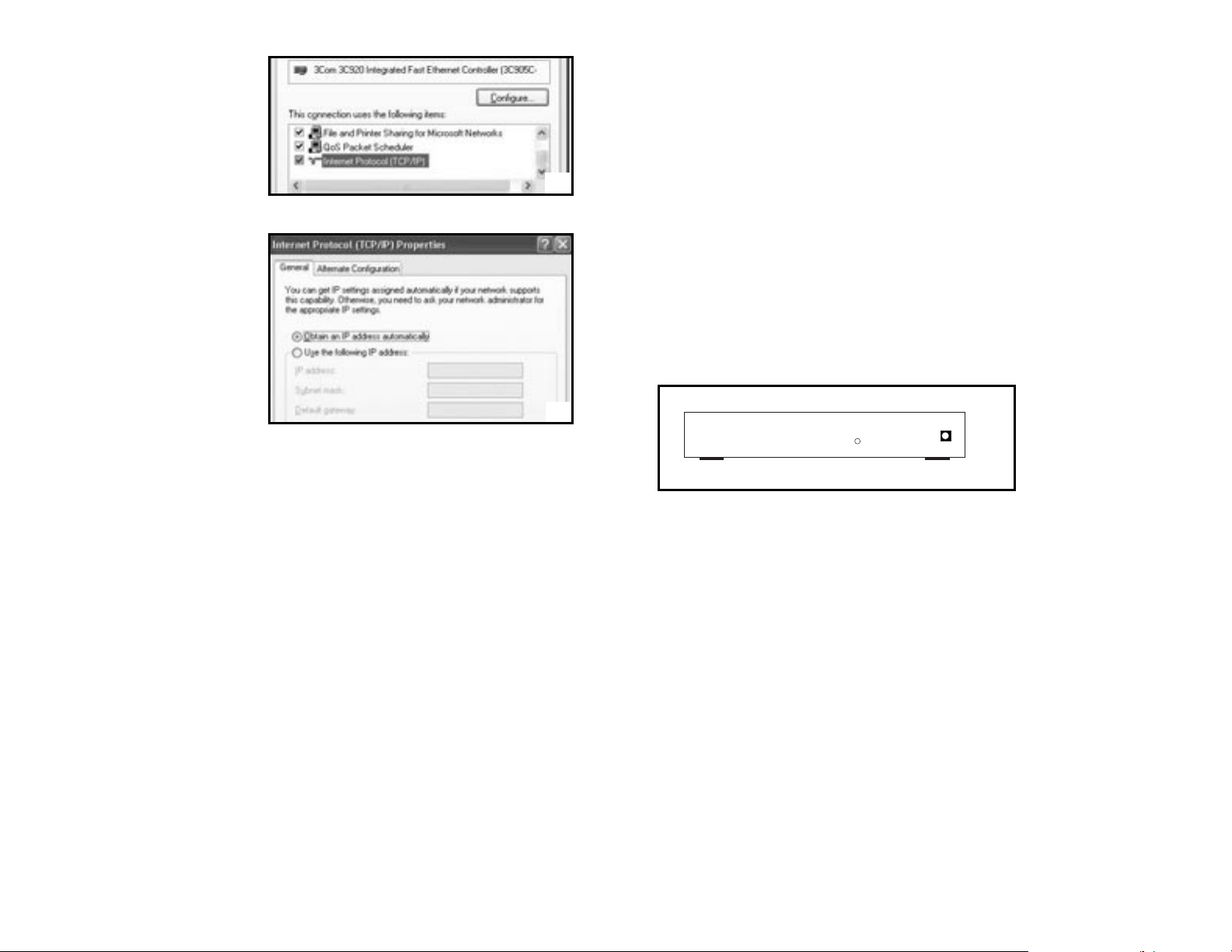
4. In the Configuration window, select
the TCP/IP protocol line that has
been associated with your network
card or adapter. (Figure 33)
5. Click Properties button, then choose
IP Address tab. Select Obtain an IP
address automatically. Press OK.
You have completed the client
settings. (Figure 34)
NOTE: Windows may ask you for original
Windows installation files, supply them
as needed.
4: SPECIFICATIONS
Technical Specifications
Standards IEEE 802.3, IEEE 802.3u
Protocol: CSMA/CD, PPPoE, PPP, PPTP Client, ARP, DHCP Client and Server, TCP/IP, UDP, ICMP,
RIP1/RIP2, DNS Proxy, Dynamic DNS, SNTP
Ports: Four 10/100 Mbps LAN ports (1 shared Uplink port)
One 10/100 Mbps WAN port
Connector: RJ-45 connector
Speed WAN Router 10/100 Mbps (Half Duplex), 20/200 Mbps (Full Duplex)
LAN Switch 10/100 Mbps (Half Duplex), 20/200 Mbps (Full Duplex)
Cabling Type
(Star Topology): 10BaseT: UTP/STP Category 3 or 5
100BaseTX: UTP/STP Category 5
LEDs: Power, Diag per unit. Link/ACT, FDX /COL, 10/100 per port
NAT: Translate private IP to public IP
Multiple DMZ: Support multiple public IP translate to multiple private IP
Virtual Server: Provide public services on the network
Firewall: IPSec, PPTP, L2TP pass through, Hacker Attack Prevention
Management: Web-based Configuration
LED Color Function
Diag (green): Lights to indicate the Gateway is in self-diagnosis mode during boot-up. The LED turns off
to indicate successful completion of self-diagnosis.
Power (yellow): Lights to indicate the Gateway has power.
Link/Act (green):
1. Lights to indicate a functioning network link from the Gateway through the corresponding port
(1 through 4 and WAN) to an attached device.
2. Blinks to indicate the Gateway is actively sending or receiving data over that port.
FDX/COL (green):
1. Lights to indicate a connection made through the corresponding port is running in Full Duplex mode.
2. Blinks periodically to indicate the connection is experiencing collisions.
100/10 (yellow):
1. Lights for any port to indicate that the port is operating at 100Mbps.
2. Off to indicate that the port is operating at 10Mbps while the network is still operating.
Rear Panel(Figure 2)
The rear panel of the Gateway has a power connector and one reset button.
Reset Button
CAUTION: Pressing the reset button will restore the Gateway to its factory default settings. Note that this
should be done only when all troubleshooting options have been attempted, including calling
Leviton's Technical Support at 1-800-824-3005.
Pressing the reset button during operation may create an IP address conflict between your computer and
the Gateway. If this occurs, a system reboot may be required.
INSTALLING THE GATEWAY
Preparing for Installation
Before connecting the Gateway to any network device, obtain the following information from your ISP. This
information is required to successfully configure your Gateway.
· PPPoE User Name and Password or
· Fixed Internet IP Address assigned by your local ISP
· Your Subnet Mask
· Your Default Gateway
· Your Primary DNS IP address
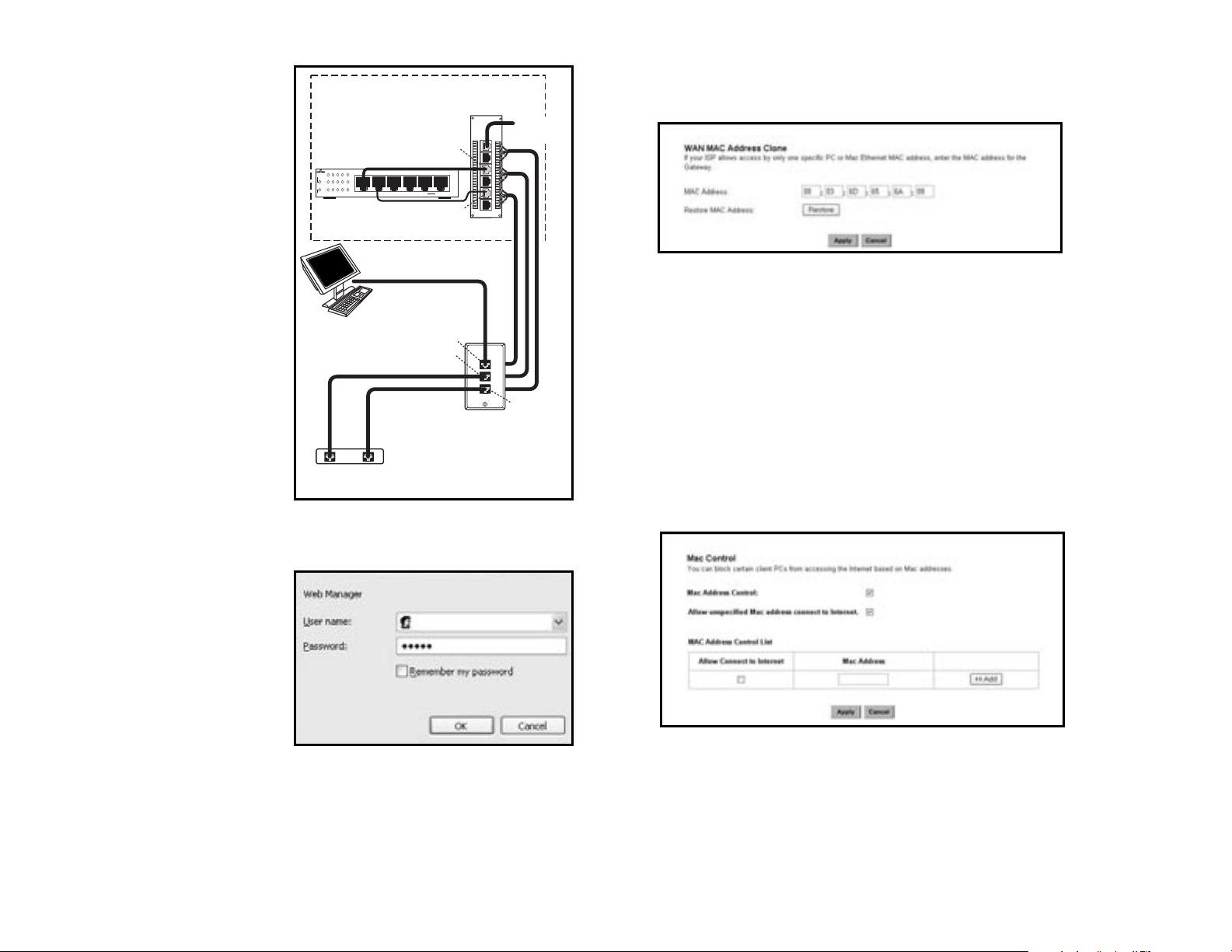
Installing and Cabling your Gateway (Figure 3)
1. Power all devices down. This should include your computers, Cable or DSL modem and the Gateway.
2. Connect one end of a standard network cable to the 10/100 RJ-45 LAN port on the Gateway, then
connect the other end of the cable to the computer.
3. Connect the Gateway to your Cable or DSL modem.
18
3
DC INPUT
RESET
2
34
33
Page 4
3. Click the “Apply” button.
WAN MAC Clone (Figure 31)
Enter the MAC Address if your ISP allows access of one specific PC’s Ethernet MAC address. Click Restore
MAC Address to return
to the default setting.
DDNS Setting
Setting the Dynamic DNS allows others to access your FTP or Web service on your computer using DNSlike address.
DDNS Status: Choose Enabled to enable it or Disabled to ignore.
Retry Time: It allows the Gateway to make the connection again in the period you set.
DDNS Server: Choose the desired server from the drop down list. Click the Website to make the link to
the server.
Host name: It is the DNS-like address used to access your FTP or web service.
User Name: This is the user name for your account at DNS server.
Password: This is the password for your account at DNS server.
MAC Control (Figure 32)
This feature allows you to block certain specific PCs accessing your ISP.
CONFIGURING YOUR COMPUTERS TO CONNECT TO THE GATEWAY
Before you start to configure other computer to accept the IP address that your Router will provide, make
sure the network card or adapter has been successfully installed into each PC you plan to connect to the
Router. Complete the following steps to configure your computer using Windows XP:
1. Click the Start button, select Setting, then Control Panel.
2. Double Click the Network and Dial-up icon.
3. Highlight the Local Area Connection and click the button of Properties.
4. Connect one end of a standard network
cable to the RJ-45 WAN port on the
Gateway. Then connect the other end of
the cable to either a Cable or DSL modem.
5. Supply the power to the Gateway using the
supplied AC/DC Power Adapter.
When the Gateway receives power, the
Power LED should remain solid Green.
6. Supply the power to either your Cable or
DSL modem.
7. Press the Reset Button to confirm the
Gateway’s factory default settings. Hold
the button in for three seconds, or until
the Diag LED illuminates red.
3: CONFIGURATION
Once the hardware installation is complete,
you may start to configure your system. Note
that this high-speed Gateway has an internal
integrated-circuit chip that programs the
administrative utility. The utility can be
accessed by any computer on the network at
http://192.168.0.1 .
Typing http://192.168.0.1 into the
computer's web browser. A pop-up screen will
appear, requesting your administration name
and password. (Figure 4) Type “admin” into
the Password field and leave the User Name
field empty.
After you access the utility, you can find
detailed instructions and explanations by
clicking each page’s Help button located in the
left panel.
NOTE: To save any setting, click the "Apply"
button, and then click "Continue". To
clear any input prior to saving it, click
"Cancel".
NOTE: If you have completed the basic
configuration of the Gateway, you may
refer to the section titled "Configuring
Your Computers to Connect to the
Gateway".
4
17
3
4
32
31
Internet Gateway
10/100 Mbps 4-port Internet Gateway
Link/Act
Diag
Fdx/Col
100/10
WAN
Power
Computer with
Network Interface Card
Computer/Ethernet
Inside the SMC
1
3
1
4
2
Patch Cord
DSL/Telephone Line
DSL Modem
Telephone
234
Patch Cord
Patch Cord
Patch Cord
UplinkWAN
Voice & Data
A
B
B
A
Category 5e
Module
Wallplate
Phone from
Telephone Line
Distribution Module
B
A
Te lephone
Page 5

THE SETUP WIZARD
The Gateway's Setup Wizard will guide you step by step to configure network. Please follow the
instructions as the wizard's pages request and change the settings in accordance to the information
provided by your ISP.
If you use a DSL modem for broadband access, please go to the sectioned titled "PPPoE Connection
for WAN". If a fixed IP is used, please read the section titled "Fixed IP for WAN". If you're using a calbe
modem, please refer to 3.2.4 Dynamic IP for WAN.
PPPoE Connection for WAN
If your ISP uses PPPoE (Point-to-Point Over Ethernet) to communicate with end-users, you will need
information such as User Name and Password from your ISP. To set up a PPPoE connection for WAN,
configure your computer. (Figure 6)
5
16
Create a Static route entry as follows:
1. Select “Static Routing” from the drop down list.
2.. Enter the following data to set the Static Routing:
Destination LAN IP
You can create a static route by entering the IP address of the remote host or network. If you wish to build
a route to the entire network, be sure to set the network portion of the IP address to zero (0).
Subnet Mask
The Subnet Mask determines which portion of an IP address is the network portion, and which portion is
the host portion.
Gateway IP
This is the address of the Gateway device that allows for a contact between the Router and the remote
network or host.
Dynamic Routing:
Dynamic Routing can be used to cache routes learned by routing protocols, thus allowing the automation
of static routing maintenance. The Gateway, using the RIP protocol, determines the network packet’s route
based on the fewest number of hops between the source and the destination. In this case, you could
automatically adjust to physical changes in the network’s layout. Complete the following steps to set up
dynamic Routing:
1. Choose the Working Mode.
Gateway Mode means the Gateway hosts your network’s connection to the Internet.
Router Mode means there is more than one Gateway on your network.
2. Select Dynamic Routing from the drop down list and choose the protocol you wish to use on your
network.
5
6
30
Page 6
Name: Enter the desired name in the column.
Status: Choose Enabled to enable it or Disabled to ignore.
IP Address: Set IP addresses to be detected by users.
WAN Address: If more than one Alias Address is set in section 3.2.5 the Alias IP Setup, you can get
multiple WAN IP addresses to choose. The following screen will appear with a pull-down
column in WAN Address.
Service Port: You can arrange certain range of ports to each profile. The minimum number is 0, and the
maximum port number is 65535.
ROUTING
Static Routing: (Figure 30)
You may set up a static route if your want to connect your Gateway to more than one network. A static
route is a pre-determined pathway that network information must travel to reach a specific host or
network.
Field Definitions:
The Max Idle time is the amount of time you would like to pass before the Gateway disconnects from the
Ineternet due to inactivity. Enter zero (0) in the field to remain connected despite idle time. The idle time
ranges from 0 to 60 minutes.
The Maximum Transmit Unit (MTU) is a feature which determines the maximum number of bytes
transmitted per packet. This should not be changed unless directed by your ISP.
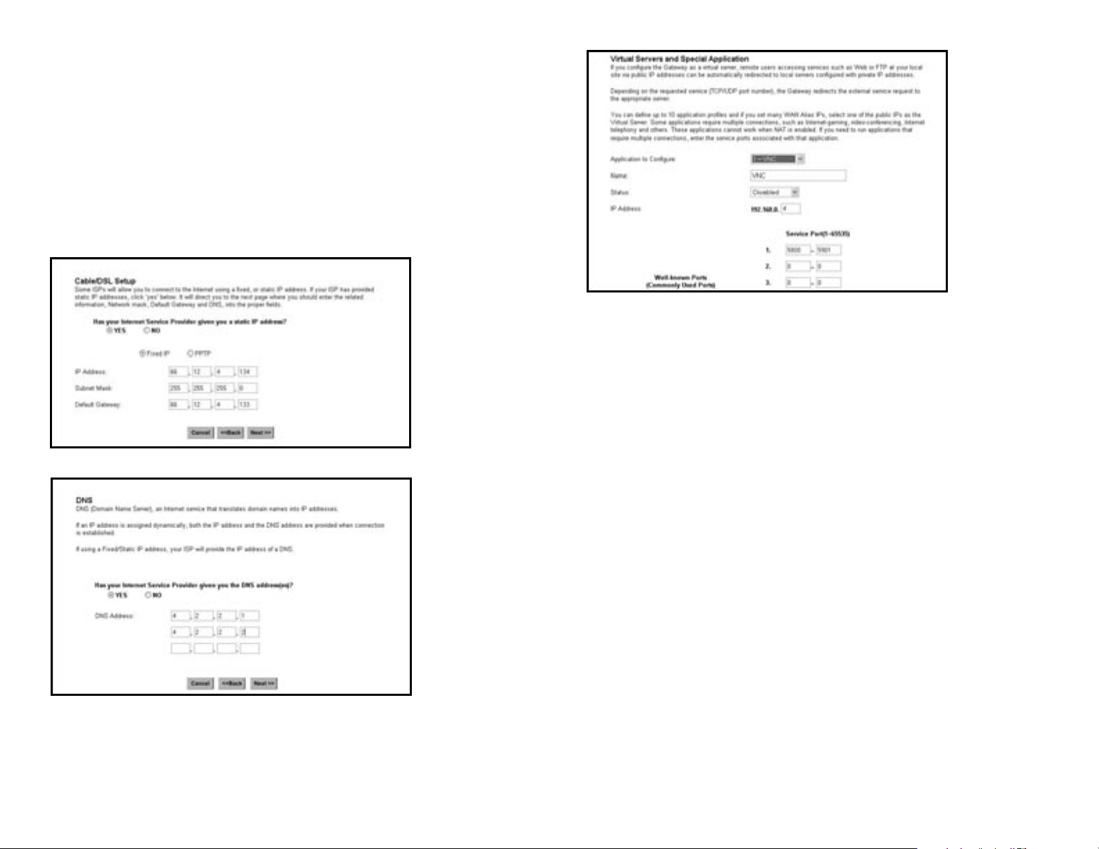
Fixed IP for WAN
If your ISP has assigned a static IP address, you may connect to the Internet using a fixed, or static
address. To set up a Fixed IP for WAN, follow these steps.
1. Choose “YES” when prompted with this screen:
2. Using the information obtained from your ISP (Figure 7), enter the IP Address, Subnet Mask and
Default Gateway as required. Then click the “NEXT” button.
3. At the next prompt (Figure 8), enter the DNS Address.
66
15
7
8
29
Page 7

PPTP For WAN (Figure 9)
1. Choose “YES” and "PPTP" when prompted with this screen:
2. Click “Next”. On the next screen, enter the information for PPTP Account, PPTP Password, and Host
Name. Using the information provided by your ISP, enter the information for “My IP Address” and ”My
Subnet Mask”. (Figure 10)
Dynamic IP for WAN (Figure 11 and 12)
If your ISP did not provide IP address, Subnet Mask, Default Gateway and Primary DNS IP address
information, choose “NO” in both screens.
Privilege (Figure 28)
Privilege setting allows you to keep certain PCs on your network from accessing to the Internet. You can
set up a filter through an IP address or network port number. Users who have their IP address or Port
number listed on the “Blocked Private Address” field or “Block Private Ports” field will no longer be able
to access the Internet.
Virtual Servers (Figure 29)
You can set up public services on your network by configuring the values in the Virtual Servers Setting
menu. You may assign certain IP addresses as the destination of the network information. When users
from the Internet make certain requests of your network, the Router will forward those requests to the
appropriate computer. Leviton suggests you assign a static IP address for server computer.
This function is generally used to set up a web server, ftp server, or e-mail server on your network. Figure
3-28 shows the screen of Virtual Servers Menu.
To add a Virtual Server:
1. Select the Profile number used by the server.
2. Click on the “Name” column and enter the application name.
3. Select Enabled or Disabled to enable or disable the profile.
4. Enter the IP Address of the server that you want the Internet users to be able to access.
5. Configure as many entries as you would like until all the link entries are filled.
6. Click the “Apply” button to save the settings.
Application to Configure: You can choose one of 10 applications to configure.
14
7
9
10
11
28
Page 8

Firewall Setting (Figure 27)
NAT allows all of the computers on your network to use one IP address.
Hacker Attack Protect keeps your network away from hacker attacking.
Block Hacker Scan is used to hide the Gateway so that the hackers won’t find it on the network.
Remote Management makes you able to manage the Gateway from Internet.
DMZ Host IP Addresses can allow one local user to be exposed to the Internet. As local user wish to use
some special-purpose service such as Internet game or Video-conferencing.
If you make the DMZ Host IP Address enabled, the following screen will appear.
Your can choose the WAN IP set up previously in the section entitled "Alias IP Setup" as your IP address.
You can enter the desired IP address number in the blank of the LAN IP.
Alias IP Setup (Figure 13)
The Alias IP Setup allows you to enter a maximum of 5 IP addresses that can be distributed to your
computer. Note that this function is effective only when your ISP supports it. If you want to delete the
entered IP address, pull down the IP address and highlight the address you want to delete. Click "Delete
this entry".
The Virtual Server and DMZ Host IP Addresses application require more than one IP address which Alias
IP supports.
DNS (Figure 14)
Select DNS from the Setup Menu. The following screen will appear, then enter the DNS Address obtained
from your ISP.
8 13
12
13
14
26
27
Page 9
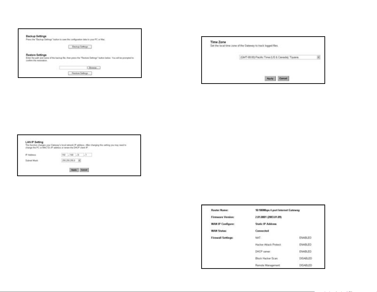
Backup (Figure 24)
You can save and restore the current configuration file to your computer.
Setup the Advanced Features
Once you’ve configured the basic settings discussed in section 3.2, you may move to the settings of
Advanced Features. In this section, we’ll explain the setting of LAN IP,DHCP,Firewall, Privilege, Vir tual
Servers and the Routing. You may set up the Advanced Features by clicking the “Advanced Features”
button on the left column of the page.
LAN IP Setting (Figure 25)
The LAN IP and Subnet Mask of the Gateway are the values seen by the users on their internal network.
The default value is 192.168.1.1 for IP and 255.255.255.0 for Subnet Mask.
DHCP Setting (Figure 26)
A DHCP (Dynamic Host Configuration Protocol) Server automatically assigns IP address to each computer
on your network. Unless you already have one, it is highly recommended that your Gateway be set up as
a DHCP server. Simply fill out the values of each entry and click the “Apply” button. DHCP Setting:
· Do you want to enable DHCP Server on this Gateway?
Click the “Enable” option to enable the DHCP server. Note that you can’t have two DHCP servers on the
network at the same time. Set the Gateway’s DHCP option to “Disable” if you already have one DHCP
server on your network.
· Number of DHCP Users
Enter the maximum number of PC that you want the DHCP server to assign IP addresses to, with the
absolute maximum being 253.
· Starting IP Address
Enter a numerical value for the DHCP server to start with when issuing IP address.
Time (Figure 15)
Select the appropriate Time Zone for your Gateway; this will help in tracking activity and hacker attempt
logs.
GATEWAY STATUS PAGE (FIGURE 16)
Status
This screen provides the current information of the device. All of the information provided is read-only.
· Router Name: You will see the name of this device in this field.
· Firmware Version: You will see the installed version of the firmware.
· WAN IP Configure: This field shows whether or not you have enabled the use of PPPoE connection,
Static IP or Dynamic IP.
· Firewall Settings:
-NAT allows all of the computers on your network to use one IP address.
-Hacker Attack Protect keeps you from hackers’ attack.
-DHCP server shows the status of the router’s DHCP server function.
-Block Hacker Scan makes your Router invisible so that hackers cannot find your Router on the network.
-Remote Management allows you to manage this device from the remote site via the network.
· LAN: These fields display the current IP address and Subnet Mask of the router as seen by the users on
your internal network.
· WAN: These fields display the IP Address, Subnet Mask and Default Gateway of the router as seen by
external users on the Internet. DNS (Domain Name Server) shows the IP address of the DNS currently
being used.
9
12
16
15
24
25
Page 10

3.4 VIEWING THE TOOLS
System Log (Figure 20)
You can acquire the information of the system in this screen, including the time, the type and the
message.
Hacker Log (Figure 21)
You can detect the intrusion from this screen. This screen shows the information of the unauthorized
access request to your network.
Reset (Figure 22)
You have two options to reset your Gateway. If you choose “Restart”, the Gateway will reboot yet retain
all the previous configuration settings. On the other hand, if you choose “Restore Factory Settings”, the
Gateway will remove all the previous settings and go back to the factory state.
For more information about “Reset”, see Page 3 Caution: Reset Button.
Upgrade (Figure 23)
You may download the latest firmware version from us. To upgrade Gateway’s firmware, simply click the
“Browse” button on the Upgrade Menu Screen and find the firmware upgrade file that you download from
the our website. Then, click the “Start” button.
DHCP Table (Figure 17)
This table shows the number of clients who exist on your DHCP pool and their information such as MAC
Address, Computer name and IP Address.
Routing Table (Figure 18)
You will see the current routing configuration such as the address of Destination LAN IP, Default Gateway,
Subnet Mask, Metric and the Interface (LAN or WAN).
DDNS Status Screen (Figure 19)
This Gateway supports the DDNS service allowing you to use one specific DNS name while the actual IP
address changes. You can see the Dynamic DNS status from this screen. This screen shows the
information of the connection status for the supported DDNS ser ver.
10
11
22
21
20
19
18
17
23
 Loading...