

Page 1

Installation Instructions
For Use With Gravity 2-inch Remodel Downlight & Adjustable
(GD2DR, GD2DS, GD2AR & GD2AS)
ISR1082R2
1 of 6
WARNING
!
Risk of electrical shock . Disconnect power
before servicing or installing luminaire.
WARNING
!
Risk of injury or damage. Luminaire will
fail if not installed properly. Follow
installation instructions.
WARNING
!
Risk of injury. Wear safety glasses and
gloves during ins tallation and servicing.
Allow ample time to cool before handling.
IMPORTANT SAFETY INSTRUCTIONS
■ Read all installation instructions before installing. It is important to save these instructions.
■ Only install and connect LED module with power disconnected at the circuit breaker. Hot plugging, or connecting the module with
power on, could damage the LEDs and is not covered by warranty.
■ Connectors on modules and approved housing are keyed for specific voltage combinations; do not force or attempt to bypass
connectors.
■ Observe and follow all label information and instructions regarding dry, damp and wet location listings, proper Intense LED module,
warnings of installation near combustible materials and/or insulation.
■ Turn off power at circuit breaker before attempting to install or perform maintenance on the fixtures.
■ Be sure to connect ground wire to prevent electric shock or other potential hazards.
■ The product must be installed in a manner consistent with the intended use and in compliance with the national electrical codes and
local codes by a person familiar with the construction and operation of the product and the hazards involved.
■ Do not block the trim aperture as this may cause unsafe operating conditions.
■ WARNING: RISK OF FIRE. Non-IC fixture requires that insulation must be kept at least 3” away from all sides of the fixture.
Minimum of 90°C supply conductors. Consult a qualified electrician before installation.
WARNING:
Use only Intense Lighting trims listed for use with this fixture. Use of trims other than those listed by Intense Lighting is a
violation of N.E.C 1103(B) and voids all warranties.
Main Housing View, Assembled
With Housing Components
Housing Lanyard
Module Quick Connect
Driver / Splice Housigs
Gravity 2-Inch
Module
Remodel Frame
Round Collar Square Collar
Ceiling Height
Adjustment Hardware
Thermal Switch
Driver / Splice Cover Plate
Standalone Optics
IPOP45NS
IPOP45SP
IPOP45NF
IPOP45FL
IPOP45WF
IPOP45VF
Availab le Filter Media
PFL2-45
PFL4-45
(7° Narrow Spot)
(16° Sp ot)
(24° Narrow Flood)
(36° Flood)
(48° Wide Flood
(60° Very Wide Food)
Hex Louver
Soft Focus Film
INSTRUCTIONS L/M-03302020 P-1
INTENSE LIGHTING | 3340 E L a Palma Ave, A naheim, CA 92806 | tel 714 63 0-9877 | fax 714 630-9883
For Intense Lighting’s li mited product warrant y, go to www.i ntenselig hting.com. F or a printed copy of the w arranty, y ou may call 80 0 961-5321.
© 2020 In tense Light ing, LLC. Al l rights res erved. No te: This docume nt is subject t o change with out notice.
Page 2

Installation Instructions
For Use With Gravity 2-inch Remodel Downlight & Adjustable
(GD2DR, GD2DS, GD2AR & GD2AS)
ISR1082R2
2 of 6
COLL AR HEIGHT SETTING:
Before installing remodel frame into ceiling set tension to ceiling thickness as
indicated (Note: Ceiling adjustment hardware is NOT ACCESSIBLE BELO W
CEILING because of small aperture size)
■ 1/2” setting for single 1/2” sheet rock or laminated MDF (Fig. 1) (Note: 1/2”
minimum ceiling thickness)
■ 5/8” setting for single 5/8” sheet rock (Fig. 2) (Note: 5/8” maximum ceiling
thickness)
■ 1-1/4” setting for double 5/8” sheet rock (consult factory for thicker ceilings.
(Fig. 3) (Note: 1-1/4” maximum ceiling thickness)
*Sho wn As Inst alled*Sh own As Ins talled *Sho wn As Inst alled*Sh own As Ins talled *Sho wn As Inst alled*Sh own As Ins talled
1/2”
Ceiling Height
Adjustment Settings
1/2”5/8”1-1/4”
5/8”
Fig. 1 Fig. 2 Fig. 3
REMOVE COVER PLATE:
1. Remove (2) M3 pan head screws and junction box cover plate
2. 2. Remove knockout on cover plate and attach flexible conduit or RomexRemove knockout on cover plate and attach flexible conduit or Romex
enough conduit to ensure that driver box can be pulled through ceiling aperture)enough conduit to ensure that driver box can be pulled through ceiling aperture)
®®
cable ( cable (Note:Note: Use Use
3. Insure conduit connection clamp does not interfere with cover sitting flush
Note: Do not remove factory wiring, only pull cover plate out far enough to make electrical
connection to supplied power.
2 3
Ceiling Opening
Conduit/Romex
HOUSING INSTALL:
1. Insert driver housing through ceiling opening
2. Rest the driver housing in the ceiling plenum
3. Fold remodel frame and push assembly into
ceiling opening
Driver/Splice
Housing
4. Allow remodel frame to spring open and align
with ceiling opening
5. Insure module quick connector is accessible
Cover Plate
through opening
Ceiling Height
Adjustment Hardware
1-1/4”
1
COLLAR INSTALLATION:
1. 1. Push blue attachment clips flush against Push blue attachment clips flush against
ceiling. Align collar at blue attachment points ceiling. Align collar at blue attachment points
with blue clips.with blue clips. (See Fig. 1)
2. Grip attachment clip and pull tension down
below ceiling level and engage clip onto
attachment point (Fig. 2)
3. Repeat step on other side of collar while
holding collar in place
4. Collar should be flush against the ceiling and
clip evenly placed in position (see detail)
Pan Head (2 PCS)
2x Collar Attachment
Clip (Blue)
Below Ceiling Detail View
Flex Conduit
Module Quick
Connect
M3 x 6mm
Collar Attachment
Clip (2 Pcs)
Fig. 1 Fig. 2 Detail View
Remodel
Frame Edge
4
Correct Tension
Cable Alignment
Collar Clip Attachment Point
(Blue) Both Sides
INSTRUCTIONS L/M-03302020 P-2
INTENSE LIGHTING | 3340 E L a Palma Ave, A naheim, CA 92806 | tel 714 63 0-9877 | fax 714 630-9883
For Intense Lighting’s li mited product warrant y, go to www.i ntenselig hting.com. F or a printed copy of the w arranty, y ou may call 80 0 961-5321.
© 2020 In tense Light ing, LLC. Al l rights res erved. No te: This docume nt is subject t o change with out notice.
Correct Clip
Alignment
Page 3

Installation Instructions
For Use With Gravity 2-inch Remodel Downlight & Adjustable
(GD2DR, GD2DS, GD2AR & GD2AS)
ISR1082R2
3 of 6
MODULE INSTALLATION:
1. Check that power is off at breaker, hot
plugging may damage LEDs.
2. Install module at 0º angle
3. Connect female quick connect from
housing to male quick connect on
module, insure that the connector latch
has snapped into place (Fig. 1)
4. 4. While holding opposite sides evenly While holding opposite sides evenly
push module to snap into channelpush module to snap into channel and
confirm module sits parallel to ceiling
line and is securely fastened into
housing (Fig. 2)
NOTE: Must keep minimum of 8-inch of
space BEtween LED module and driver
housing
AIMING FEATURE (ADJUSTABLE MODULE ONLY):
Counter balanced fixture design allows for adjustment without use of fastening
hardware. Precise offset center beam adjustment allows for maximum output with no
cut off from downlight to 45° tilt positions (ceilings over 1-1/4” thick slightly reduce tilt
adjustment.) Screwdriver can be used for hot aiming.
Quick Connect
LED Module
Fig.1 Fig.2
Side View
Collar
Snap In Channel
LED Module
Bottem View
Connector Latch
Collar
Locking Set Screw
6A 6B
ROTATIONAL ADJUSTMENT:
1. Place thumb and index finger at rotational tabs and turn fixture to desired position
2. Leave fixture into desired position
5
VERTICAL ADJUSTMENT
(ADJUSTABLE MODULE ONLY):
1. Insert screwdriver into module
adjustment feature, push module
back towards desired position or
pull forward to 0° for downlight
position
2. Leave fixture in desired position
Tilt Adjustment
Feature
Rotational
Tabs
6C
Tilt Adjustment
Position Indicators
INSTRUCTIONS L/M-03302020 P-3
INTENSE LIGHTING | 3340 E L a Palma Ave, A naheim, CA 92806 | tel 714 63 0-9877 | fax 714 630-9883
For Intense Lighting’s li mited product warrant y, go to www.i ntenselig hting.com. F or a printed copy of the w arranty, y ou may call 80 0 961-5321.
© 2020 In tense Light ing, LLC. Al l rights res erved. No te: This docume nt is subject t o change with out notice.
Page 4

Installation Instructions
For Use With Gravity 2-inch Remodel Downlight & Adjustable
(GD2DR, GD2DS, GD2AR & GD2AS)
ISR1082R2
4 of 6
TRIM INSTALLATION:
1. Position trim clips to collar
attachment locations
2. Press trim against ceiling until
flush with ceiling
Locations (4 Places)
ACCESSORY INSTALLATION:
1. Remove LED module (See page 5, Section S1 & S2 for
instructions)
2. Once LED module is removed, remove plastic cap from
module assembly by gripping cap and pulling snaps
away from module at slight angle (Fig. 1)
3. Install accessories into cap and press until snapped
into place (Hex louver and film position interchangable)
4. Reinstall plastic cap by aligning white dot towards
center of tilt adjustment feature and snap flush against
module
5. Reinstall LED module (See page 3, section 5 for
insturctions)
Clip Attachment
White Dot
Tilt Adjustment
Feature
Fig.1
Attachment
Snaps
7
Clip Attachment
Locations (4 Places)
8
Film Alignment Tab
Plastic Cap
Film Alignment Tab
OPTIC REPLACEMENT:
1. Remove LED module (See page 5, Section S1 & S2 for
instructions)
Tilt Adjustment
Feature
Fig.1 Fig.2
2. Once LED module is removed, remove plastic cap from
module assembly by gripping cap and pulling snaps away
from module at slight angle (Fig. 1)
3. To remove secondary optic, turn secondary optic tab
slightly counter clockwise to remove from snap position
(tip of screwdriver can be used against side of tab) (Fig, 2)
4. To install secondary optic, align triangle marks on optic
and opening as shown on Fig, 2
White Dot
Film Alignment Tab
5. Use protective paper shipped with film and press
secondary optic against center of primary optic with
finger, then turn tab clockwise until snaps into position
Attachment
Snaps
6. Reinstall plastic cap by aligning white dot towards center
of tilt adjustment feature and snap flush against module
Plastic Cap
7. Reinstall LED module (See page 3, section 5 for
insturctions)
INSTRUCTIONS L/M-03302020 P-4
INTENSE LIGHTING | 3340 E L a Palma Ave, A naheim, CA 92806 | tel 714 63 0-9877 | fax 714 630-9883
For Intense Lighting’s li mited product warrant y, go to www.i ntenselig hting.com. F or a printed copy of the w arranty, y ou may call 80 0 961-5321.
© 2020 In tense Light ing, LLC. Al l rights res erved. No te: This docume nt is subject t o change with out notice.
Film Alignment Tab
9
Optic Beam Angle
Triangle Alignment Mark
Lock Direction
Center of Optic
Page 5
Installation Instructions
For Use With Gravity 2-inch Remodel Downlight & Adjustable
(GD2DR, GD2DS, GD2AR & GD2AS)
TRIMLESS INSTALLATION:
ISR1082R2
5 of 6
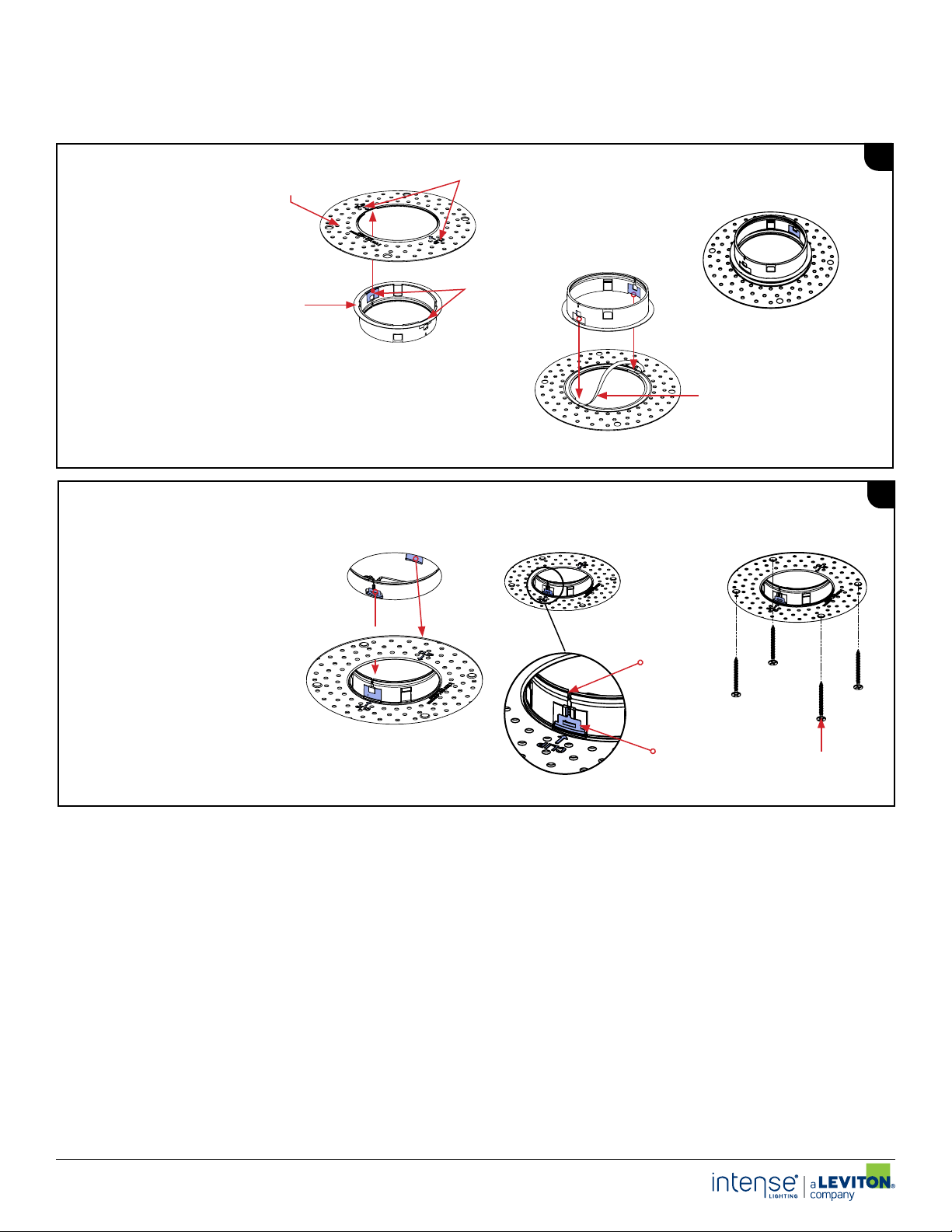
TRIMLESS MUD RING INSTALL:
1. Find the orientation features (blue
clip location on mud ring) and align
With the blue indicators on collar
(Fig. 1)
2. Peel off backing on mud ring (Fig. 2)
3. Press the collar into the mud ring
(Fig. 3)
TRIMLESS INSTALLATION
1. Align collar at blue attachment points with
blue clips. Push collar flush against the
ceiling (Fig. 1)
2. Grip attachment clip and pull tension
down below ceiling and engage clip onto
attachment point, push flush to ceiling (Fig. 2)
3. Repeat steps for other clip
4. Mud ring should be flush against the ceiling
and the clip evenly placed in position
5. Secure perforated mud ring to housing using
#6 drywall screws (supplied by others) (Fig. 3)
6. Insure mud flange is centered to fixture
opening
7. Apply joint compound over perforated mud
ring and feather out accordingly
Mud Flange
Collar
Fig. 1
Fig. 1
L3
Blue Clip
Blue Indicators
Fig. 3
Fig. 2
Fig.2 Fig.3
Tension
Attachment Point
#6 drywall screws
L1
L2
INSTRUCTIONS L/M-03302020 P-5
INTENSE LIGHTING | 3340 E L a Palma Ave, A naheim, CA 92806 | tel 714 63 0-9877 | fax 714 630-9883
For Intense Lighting’s li mited product warrant y, go to www.i ntenselig hting.com. F or a printed copy of the w arranty, y ou may call 80 0 961-5321.
© 2020 In tense Light ing, LLC. Al l rights res erved. No te: This docume nt is subject t o change with out notice.
Page 6

Installation Instructions
For Use With Gravity 2-inch Remodel Downlight & Adjustable
(GD2DR, GD2DS, GD2AR & GD2AS)
LED MODULE & DRIVER SERVICING:
ISR1082R2
6 of 6
TRIM REMOVAL:
1. Remove trim from fixture by pulling trim out one
side at a time.
2. To reinstall trim please see page 4, section 9
DRIVER BOX REMOVAL:
1. Once LED Module is out of the way, locate the
Ceiling Opening
driver box and pull it through the ceiling opening.
Conduit/Romex
LED MODULE REMOVAL:
1. Check that power is off at
breaker, hot plugging may
damage LEDs.
2. Adjust the LED module to 0º
angle (See page 3, section 8 for
details)
3. Pull module down to unsnap it
Quick Connect
from the collar channel
4. Disconnect quick connect from
housing by pressing on the
connector latch
5. To reinstall LED module please
LED Module
see page 3, section 5
S3
DRIVER SERVICING:
1. Remove (2) M3 pan head screws and junction box cover plate
2. Makes necessary maintenance and or replacement.
3. Make necessary wire connec tion, replace cover and tighten screw s once completed
4. To reinstall driver box please see page 2, section 2
S2S1
Connector Latch
S4
Driver/Splice
Housing
Below Ceiling Detail View
Module Quick
Connect
Module Quick
Connect
COLL AR ATTACHMENT SERVICING
In the event of tension cable system failure consult factory for a
replacement remodel frame in kit
1. Remove Trim (See page 6, section S1 for trim removal
instructions)
2. Remove LED Module (See page 6, section S2 for LED Module
removal instructions)
3. Pull Down Remodel Frame with Driver/Splice Housing
(See page 6, section S3 for Driver/Splice Housing removal
instructions)
4. Clip New Remodel Frame To existing Driver/Splice Housing
using the existing frame attachment point.
5. Reinsert Driver/Splice Housing and old Remodel Frame into
ceiling and Install new Remodel Frame. (See pages 2,3 & 4 for
fixture install instructions)
Remodel
Frame Edge
Ceiling Opening
Driver/Splice
Housing
Module Quick
Connect
Conduit/Romex
Frame Attachment
Point
Remodel Frame
Collar Attachment
Clip (2 Pcs)
Cover Plate
Flex Conduit
M3 x 6mm
Pan Head (2 PCS)
S5
INSTRUCTIONS L/M-03302020 P-6
INTENSE LIGHTING | 3340 E L a Palma Ave, A naheim, CA 92806 | tel 714 63 0-9877 | fax 714 630-9883
For Intense Lighting’s li mited product warrant y, go to www.i ntenselig hting.com. F or a printed copy of the w arranty, y ou may call 80 0 961-5321.
© 2020 In tense Light ing, LLC. Al l rights res erved. No te: This docume nt is subject t o change with out notice.
 Loading...