

Page 1
Installation Guide
EZ-MAX PLUS
Covering EZ-MAX Plus 8, 16 & 24 Relay Panels
Software Revision 1.0 and above.
TM
RELAY PANELS
Page 2

Table of Contents
Read this Before You Begin!
Safety Precautions!................................................................................................ 1
Warnings!............................................................................................................. 1
Overview
Introduction.......................................................................................................... 3
Product Specifications and Capabilities.................................................................... 4
Installation Overview ............................................................................................. 5
Installation Checklist.............................................................................................. 6
Relay Cabinet Mounting
Selection of a Mounting Location ............................................................................ 7
Suggested Mounting Heights............................................................................. 7
Environmental Considerations ........................................................................... 7
Preferred Areas for Conduit Entry ........................................................................... 8
Sample Electrical Room Layouts ............................................................................. 9
Mounting Provisions and Dimensions .....................................................................10
Line Voltage and Control Power Termination
Overview of Power Wiring - Feed\Line Wiring.........................................................15
Line and Load Circuit Wiring..................................................................................17
Testing the Circuits..........................................................................................17
Installing Relay Cards ......................................................................................17
Wiring the Relays ............................................................................................18
Wiring Diagrams..............................................................................................19
Control Electronics Power Wiring ...........................................................................21
Low Voltage Control Wiring
Control Overview..................................................................................................25
Input Trigger-What Determines an “ON” ...........................................................26
Low Voltage Switches
Connecting to a Low Voltage Input ...................................................................30
Occupancy Sensors
Occupancy Sensor Wiring......................................................................................33
Photocells
Photocell Wiring ...................................................................................................35
i
Page 3

Luma-Net III
Wiring Specifications ............................................................................................39
Wiring the Phoenix Connector ..........................................................................40
Emergency
Inputs and Outputs ..............................................................................................45
Terminal Locations ...............................................................................................46
Appendix A
Power-Up and Installation Verification Checklist.................................................... A-1
Appendix B
Power Considerations for Control Systems............................................................ B-1
Terminology ................................................................................................. B-1
Power Requirements and Maximum Run Length .............................................. B-2
Power Wire - Run Length............................................................................... B-4
ii
Page 4

Read this Before You Begin!
Safety Precautions!
Read and follow all safety instructions.
Apply the “Emergency Circuits” label (provided) to the front of the
door.
When using electrical equipment, basic safety precautions should
always be followed.
Do not use outdoors.
Do not mount near gas or electric heaters.
Equipment should be mounted in locations and at heights where it
will not readily be subjected to tampering by authorized personnel.
The use of accessory equipment not recommended by manufacturer
may cause an unsafe condition.
Do not use this equipment for other than intended use.
All servicing shall be performed by qualified service personnel.
SAVE THESE INSTRUCTIONS!
Leviton Service and Support:
www.leviton.com 1-800-959-6004
Warnings!
Conduit Entry Locations: The cabinets have been designed with
specific locations supporting conduit entry for line and low voltage
circuits. There are specific areas of the cabinet that are restricted
from some or all types of conduit access. See the Installation
sections of this manual for specific details.
Line and load circuit wiring: The line wiring should come from an
over-current device and the load circuit wiring should go to the
specific load to be controlled. On some models that have
integrated branch circuit protection, the line side of the relay has
been pre-wired to a circuit breaker. Only the load side of the circuits
needs to be connected with these products.
To be installed and/or used in accordance with appropriate electrical
codes and regulations.
To be installed by a qualified Electrician.
DO NOT CONNECT line voltage wires to low voltage terminals.
Mount in a location where audible noise is acceptable.
When using with fluorescent ballasts, both lighting fixture and
ballast must be grounded.
EZ-MAX Plus Installation Guide
Page 1
Page 5

Read this Before You Begin! Warnings!
Use this relay cabinet only with minimum 75o C copper wire at 75%
ampacity.
Disconnect power when servicing the relay cabinet, fixture or when
changing lamps.
Indoor use only.
TO AVOID FIRE, SHOCK OR DEATH: TURN OFF POWER AT MAIN
CIRCUIT BREAKER, OR FUSE, AND TEST THAT THE POWER IS OFF
BEFORE WIRING, OPENING THE PANEL, OR REPLACING ANY
COMPONENT!
During operation, cabinet cover is to be removed by qualified
personnel ONLY! Heed all caution markings indicating the presence
of High Voltage. High voltage may be up to 600V.
Test each circuit for short circuits before connecting it to relay so
damage to the relay and it’s electronics can be avoided.
Verify that all un-used power supply leads are insulated with wire
nuts.
Page 2
Page 6

Overview
Leviton recommends always checking our website
at http://www.leviton.com/lms for late breaking
notes, requirements, application information, and
firmware updates.
Introduction
Thank you for choosing Leviton’s EZ-MAX Plus line of products for your relay needs.
The EZ-MAX Plus product line offers a scalable solution of relay and relay controls that
can fit any application with 2 or 3-circuit needs with time clock control.
This manual is designed to assist you in the installation of your product. It includes
guidelines, requirements, and instructions that are required only for the installation
and low voltage termination of your product. The following resources are also
available to you:
• Quick Start Programming Guide (included with every panel)
• Programming Guide (included with every panel)
• Additional resources located at our website at http://www.leviton.com/lms
A hard copy of the Programming Guide is included with your system purchase. Please
contact Leviton Technical Support at (800)959-6004 to request additional copies.
This manual covers all products in the EZ-MAX Plus product line, however, the steps
shown are somewhat generic in nature. The particular requirements for your product,
especially as related to termination, may differ slightly from the steps in this manual.
Please review all markings and labels on your product to ensure that your actions are
correct.
EZ-MAX Plus Installation Guide Page 3
Page 7
Overview Product Specifications and Capabilities
Product Specifications and Capabilities
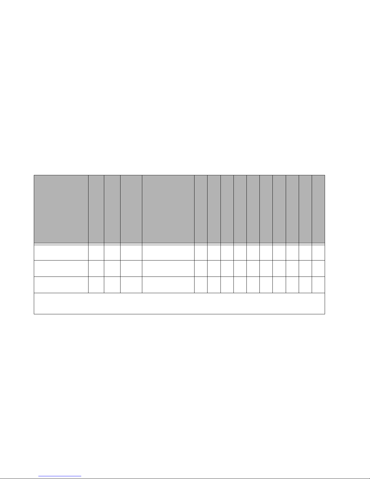
The table below gives a general overview of the specifications of all EZ-Max Plus relay
products. The table uses the following abbreviations:
Y = Yes
N = No
O = Optional
* = A single asterisk in any column indicates that there is support for this feature,
however, there are conditions that you should be aware of. Consult the specific
sections of the manual dealing with this feature for additional information and
requirements.
EZ-Max Plus
Product Type
Min-Max Relays
Relay Types
Weight (lbs (Kg))
Master Panel, 8 relays* 0-8 ** 16
Master Panel, 16 relays* 0-16 ** 44
Master Panel, 24 relays* 0-24 ** 44
Note: Voltage:120v/277v/347 @20A, 240v @20/30A
** Relay Types: 30A Latching, 2-Pole, 1-Pole (optional)
(7.26)
(19.96)
(19.96)
Figure 1: EZ-MAX Plus Product Capabilities Chart
Size
W", H", D"
(Wcm,Hcm,Dcm)
13" x 13" x 4-9/32"
(33 x 33 x 10.9)
20-1/4"x34"x4-9/32"
(54.4 x 86.4 x 10.9)
20-1/4"x34"x4-9/32"
(54.4 x 86.4 x 10.9)
Flush Mount Option
# discrete Inputs
Sw. Input Board Avail.
Luma-Net Network
Emergency Input
Emergency Output
Touch-Tone Phone
Data Modem
Front Panel Program
Y 8 N Y Y Y O* O* Y Y
Y 12 Y Y Y Y O* O* Y Y
Y 12 Y Y Y Y O* O* Y Y
Event Scheduler
Page 4
Page 8

Inspection
Carefully unpack the relay cabinet, and inspect to make sure there is no hidden
shipping damage. Report any damage to the freight carrier who delivered the system.
Claims for damages are filed with the freight carrier.
In case of damaged components, your relay cabinet may be serviced in the field with
factory replacement parts.
Installation Overview
Follow the steps below to install a remote relay cabinet:
Step 1: Mount the relay cabinet to the wall, install conduit, and pull all wire
(See “Relay Cabinet Mounting” on page 7.).
Step 2: Terminate line voltage wiring (See “Line Voltage and Control Power
Termination” on page 15.).
Step 3: Terminate any low voltage discrete input wiring (See “Low Voltage” on
page 23.).
Step 4: Terminate any network wiring (See “Wiring the Phoenix Connector” on
page 40.).
Step 5: Inspect your work (REQUIRED FOR ALL CABINETS) (See “Power-Up
and Installation Verification Checklist” on page 1.).
Step 6: Power-up and test the system.
Step 7: Install latest software/firmware from Leviton website,
www.leviton.com/lms.
Step 8: Perform all necessary configuration. (See the EZ-MAX Plus
Programming Guide)
Each of the above steps is covered in detail throughout the rest of this installation
guide. Each section contains notes, warnings, requirements, suggestions, and
procedures that will help you successfully install and use your system.
EZ-MAX Plus Installation Guide Page 5
Page 9

Overview Installation Checklist
Installation
Installation Checklist
Follow these simple steps to install the cabinet:
Step 1: Unpack the system.
Step 2: Report any damage to the freight carrier.
Step 3: If appropriate, remove any covers and/or doors.
Step 4: If appropriate, remove the mounting plate assembly and store where
damage will not occur to the electronics.
Step 5: Attach the cabinet to the wall (reference stickers inside the cabinet for
proper orientation if it is in question).
Step 6: Drill conduit entry holes if KO’s are not provided and attach conduit
where appropriate.
Step 7: Pull all wire into the cabinet.
Step 8: Test and verify all wiring by directly connecting line to load. Correct any
faults and re-test wiring before you proceed.
Step 9: If applicable, re-install any control electronics removed in Step #4.
Step 10: Terminate discrete input control wiring.
Step 11: Terminate network control wiring.
Step 12: Test each Line/Load circuit for shorts.
Step 13: Terminate the feed and load wiring to each relay.
Step 14: Blow out dust, dirt, or debris which has accumulated in the cabinet.
Step 15: Apply power to the system.
Step 16: Verify proper operation of each relay using the override buttons.
Step 17: Configure cabinet per owner’s requirements.
Page 6
Page 10
Relay Cabinet Mounting
There are several steps required when mounting your relay cabinet:
Step 1: Install the flush mounting kit if appropriate.
Step 2: Plan your conduit runs and electrical room layout.
Step 3: Determine the appropriate methods for mounting your cabinet to the
wall.
Step 4: Mount the cabinet to the wall.
Step 5: Install conduit, pull wire, and other items as required.
Step 6: Proceed to “Line Voltage and Control Power Termination” on page 15.
Selection of a Mounting Location
Choosing a mounting location for your cabinet is critical to the overall success and
ease of installation. Each style of cabinet has its own unique wiring requirements
which must be observed. Please review the next few pages, which describe and
illustrate these requirements.
Suggested Mounting Heights
Although successful operation is completely independent of mounting height, the
suggested mounting heights below were selected to locate the cabinet at a
reasonable and accessible working height.
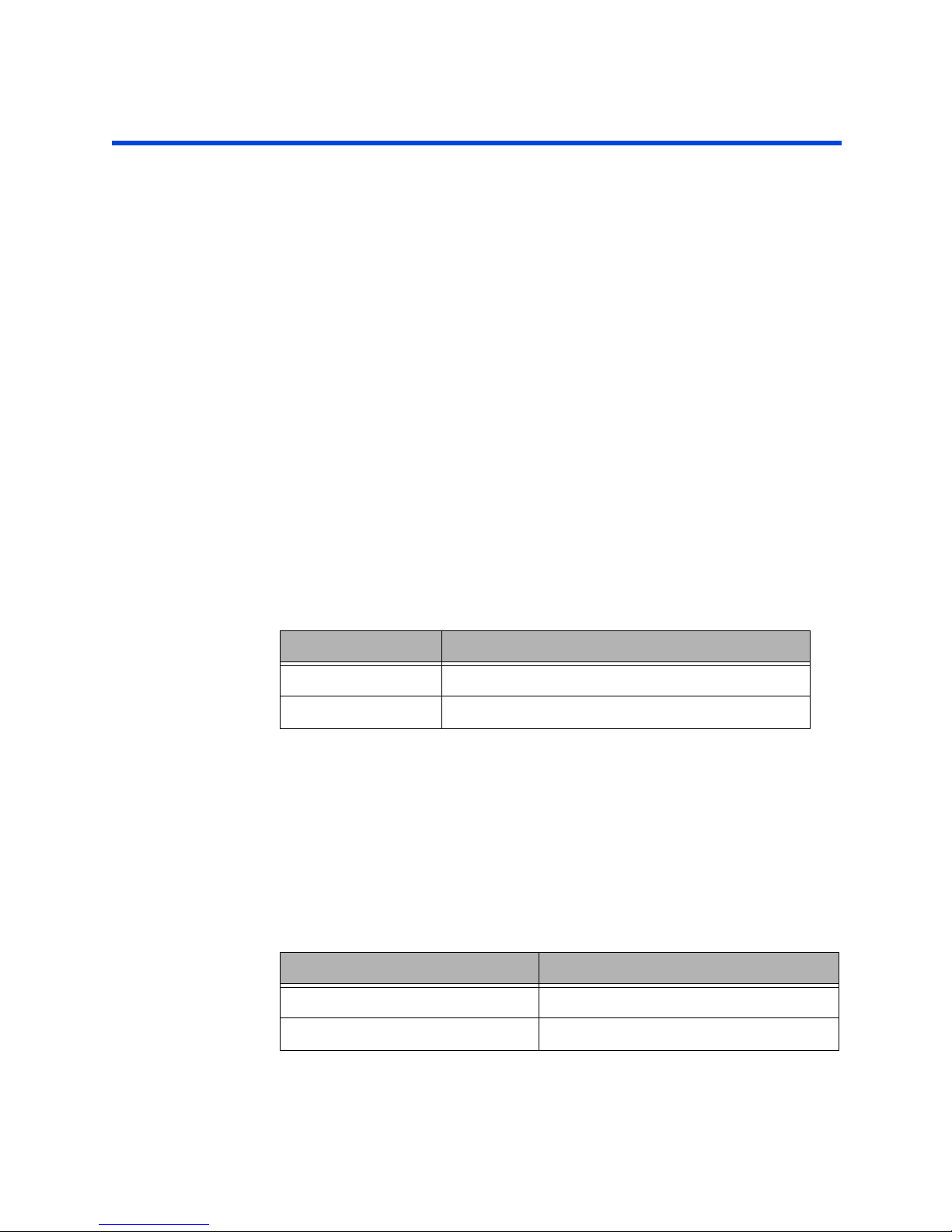
Cabinet Suggested Mounting height to bottom of cabinet
8-Relay Cabinet 53" (1,359 mm)
16/24-Relay Cabinet 32" (826 mm)
Environmental Considerations
• Cabinets generate heat (see table below). Make sure they are mounted in a
climate controlled space where the temperature will be 0-40o C (32-104oF) or
20-30o C (68-86oF) if used as Emergency Lighting Power Equipment.
• Reinforce the wall for strength as required for weight and local code.
• Clearance on left and right side of the panel should be maintained at 1 1/2" or
greater.
• Relays will click while in operation. Locate the panels where audible noise is
acceptable.
Cabinet MAX BTU/HR
8-Relay Cabinet 583
16/24 Relay Cabinet 583
EZ-MAX Plus Installation Guide Page 7
Page 11
Relay Cabinet Mounting Preferred Areas for Conduit Entry
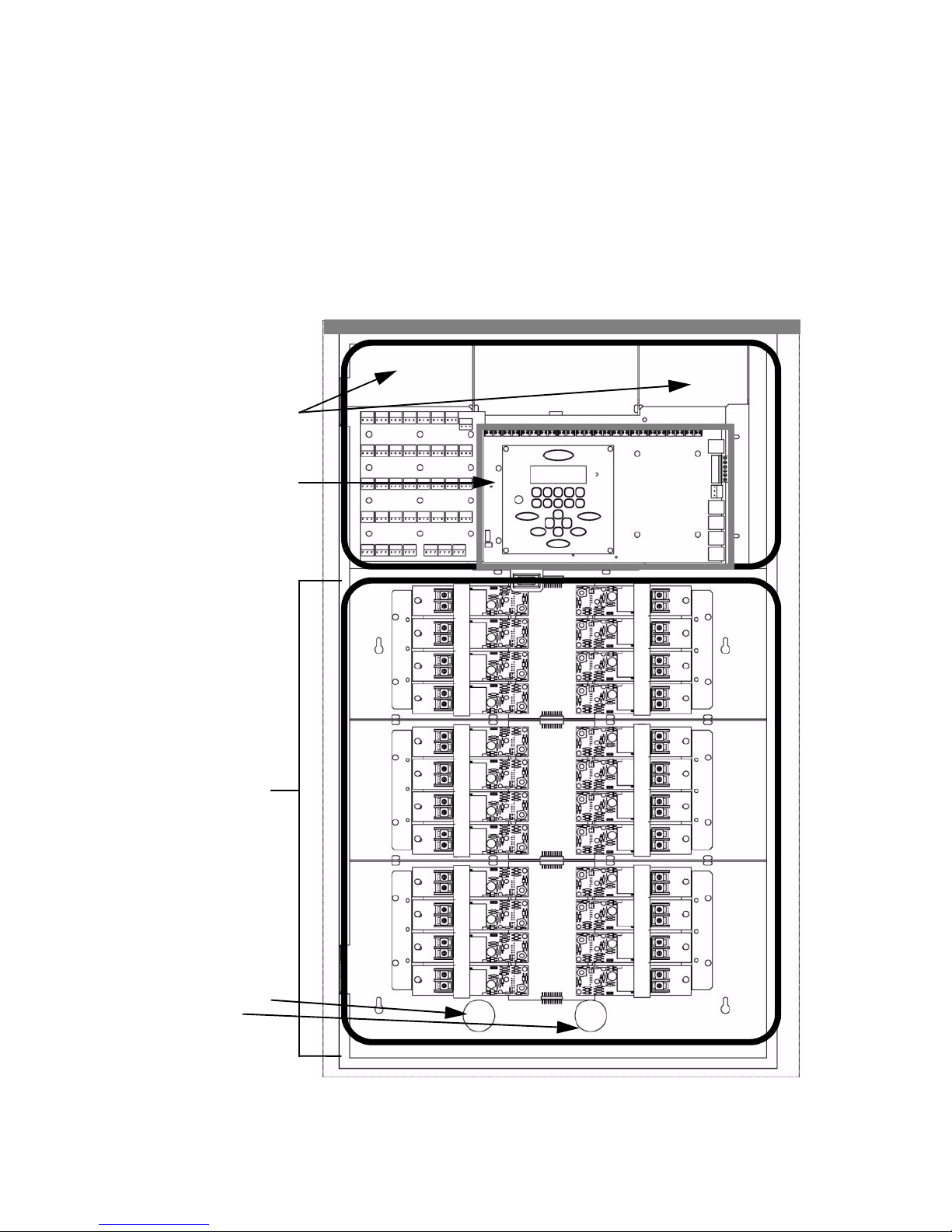
Transformer and
Grounding
Points
High Voltage Pass
Through below
control module
mounting plate
Transformer Connections
located directly below
Control Module
Low Voltage Area
High Voltage Area
Preferred Areas for Conduit Entry
Your relay cabinet has been designed for easy installation, with a variety of installation
options. Please pay close attention to the “allowed” and disallowed” areas for conduit
entry. Disallowed areas are areas where conduit entry is impossible due to physical
limitations or code limitations. These areas are clearly marked in the illustrations that
follow. Each cabinet style has designated areas for low voltage and line voltage
conduit entry. You must adhere to these requirements to ensure a successful
installation and continued code compliance.
Figure 2: 24-Relay Cabinet Conduit Entry
Page 8
Page 12
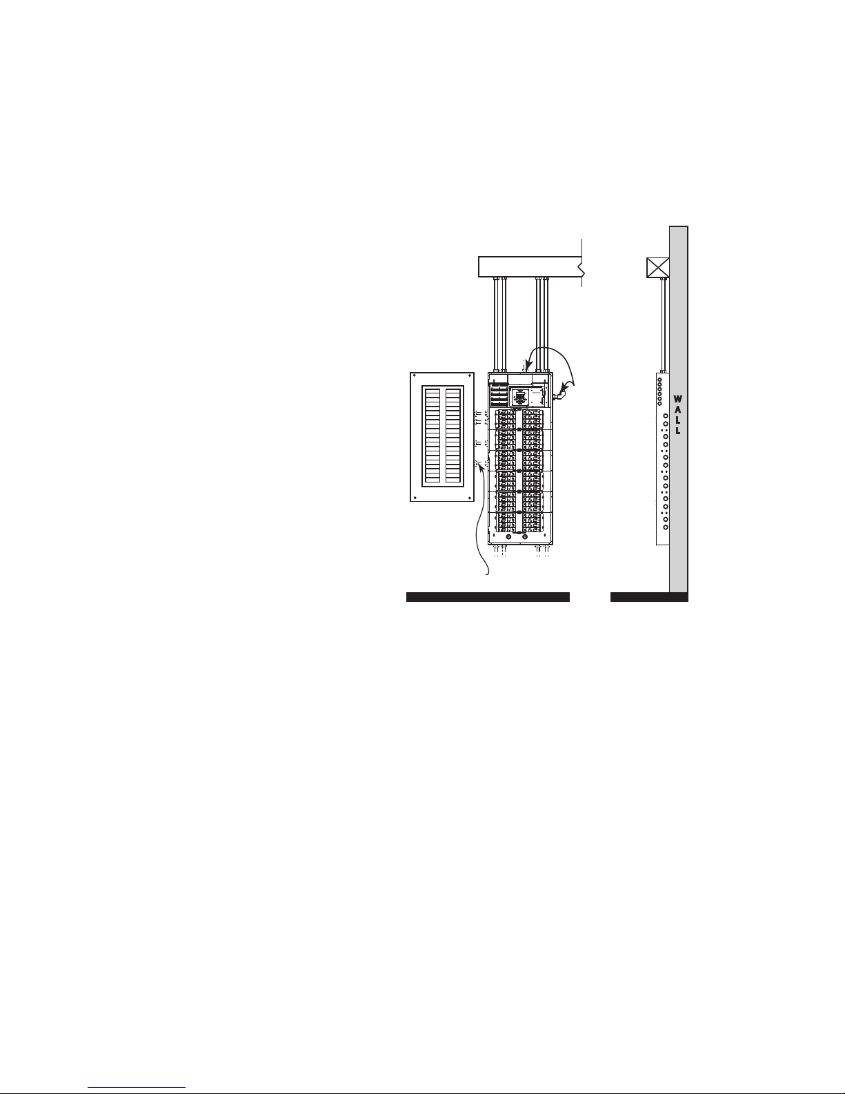
Sample Electrical Room Layouts
Front View
Wiring Raceway
Class 2/PELV
Wiring to
Controls 2 locations
Feed and/or
switch legs
to loads
Feed and/or
switch legs
to loads
Feed wiring to relays
W
A
L
L
Side View
Distribution panel
Top and Bottom Feed
and /or switch legs to loads
Surface Mounting Shown
front3
The "right" layout for your application is a decision only you can make. The layouts
depicted in the following illustrations show some simple and effective systems which
you’re welcome to use and adapt to your particular installation.
Figure 3: Sample Electrical Room Layouts for all cabinets
EZ-MAX Plus Installation Guide Page 9
Page 13
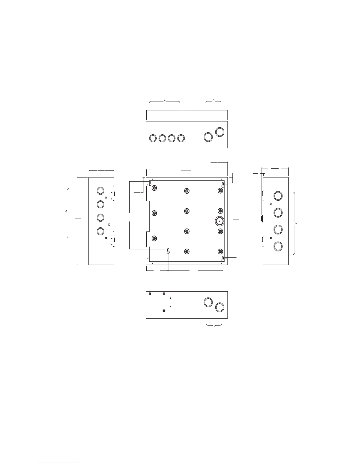
Relay Cabinet Mounting Mounting Provisions and Dimensions
3/4
[19.05]
11
279.4
27/32
[21.5]
10 3/64
[255.14]
19/32
[15.28]
8 3/4
[222.25]
3 1/2
[88.9]
11 21/32
[295.87]
19/32
15.28
13
[330.2]
4
[101.6]
SIDE VIEW
13
[330.2]
TOP VIEW
BOTTOM VIEW
(9/32)
[7.05]
(4 9/32)
[108.65]
SIDE VIEW
with door
All Dimensions are in inches
[ ] are mm
LINE / LOAD
CONDUIT ENTRY
LOW VOLTAGE
CONDUIT ENTRY
1" & 1-1/4"
LINE / LOAD
CONDUIT ENTRY
1-1/4" & 1-1/2"
4 PLACES
LINE / LOAD
CONDUIT
ENTRY
LOW VOLTAGE
CONDUIT ENTRY
1" & 1-1/4"
4 PLACES
Mounting Provisions and Dimensions
Figure 4: EZ-Max Plus 8 Cabinet mounting provisions and dimensions.
Page 10
Page 14
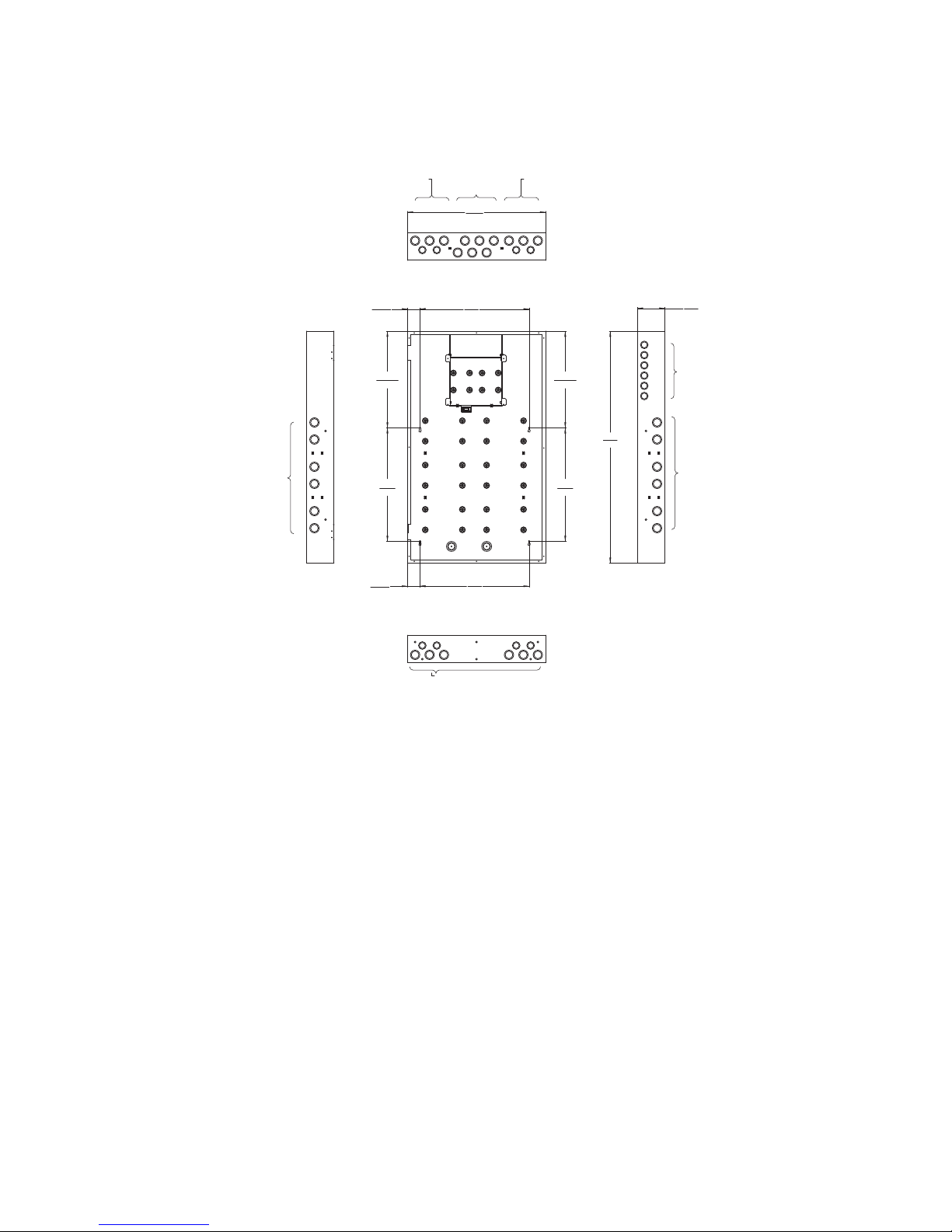
20 1/4
[514.35]
34
[863.6]
4
[101.6]
14 11/64
[359.83]
16 5/8
[422.4]
16 5/8
[422.4]
14 11/64
[359.83]
16
[406.4]
1 27/32
[46.8]
16
[406.4]
1 27/32
[46.8]
All Dimensions are in inches
[ ] are mm
LOW
VOLTAGE
CONDUIT
ENTRY
1-1/4" & 1-1/2"
6 PLACES
LINE / LOAD
CONDUIT
ENTRY
1" & 1-1/4"
6 PLACES
LOW VOLTAGE
CONDUIT ENTRY
1" & 1-1/4"
6 PLACES
LINE / LOAD
CONDUIT ENTRY
1" & 1-1/4", 2
PLACES PLUS
1-1/4" & 1-1/2", 3
PLACES
LINE / LOAD
CONDUIT ENTRY
1" & 1-1/4", 2
PLACES PLUS
1-1/4" & 1-1/2", 3
PLACES
LINE / LOAD
CONDUIT
ENTRY
1" & 1-1/4"
6 PLACES
LINE / LOAD CONDUIT ENTRY: 1" &
1-1/4", 4 PLACES PLUS 1-1/4" & 11/2", 6 PLACES
Figure 5: EZ-MAX Plus 16/24 relay cabinet mounting provisions and
dimensions.
EZ-MAX Plus Installation Guide Page 11
Page 15

Relay Cabinet Mounting Mounting Provisions and Dimensions
Step-by-step Mounting Instructions
Step 1: Choose a location to mount the cabinet. Make sure the location in a dry
area that is convenient to the branch circuit panel.
Step 2: Leviton requires that cabinet mounting hardware reach through the
drywall to wall studs or other suitable solid backing. However, properly
sized struts and suitable hardware can also be used. The load must be
evenly distributed to the anchors without exceeding the recommended
anchor limit. Using drywall screws directly through drywall without a
stud is not acceptable. Make sure that adequate support at all points is
provided. For fully loaded cabinet weights, see “Product Specifications
and Capabilities Chart” on page 3.
Step 3: Remove the cover. Some cabinets may also require the removal of data
and/or grounding wires. Make sure that this occurs prior to removal of
the door and that they are reconnected when reinstalling the door. On
cabinets with hinges, simply lift the door off the hinges. On cabinets
with screws, remove the cover screws. Appropriately store the cover for
future use.
Step 4: Before you proceed any further, see “Preferred Areas for Conduit Entry”
on page 8. This section shows the location of the mounting holes and
allowed conduit entry locations for each cabinet type.
Step 5: Verify which end of the cabinet is the top before you attach the cabinet
to any surface. Some cabinets have “up” arrows to indicate the top end.
Step 6: Attach the cabinet to its prepared mounting surface as appropriate.
Step 7: Cut, punch, or remove knockouts for the desired conduit openings. Pay
special attention to any disallowed areas for conduit entry.
Step 8: Pull all wire, both line and low voltage as appropriate.
Step 9: Carefully and completely remove any dust, debris, metal particles, etc.
from inside the cabinet in preparation for wire termination and eventual
power up.
Step 10: Proceed to “Line Voltage and Control Power Termination” on page 15.
Page 12
Page 16

Line Voltage
Page 17

Page 14
Page 18

Line Voltage and Control Power Termination
Since the panel is fed from multiple circuits, locate each one
and lock-out each feed in the OFF position.
Overview of Power Wiring - Feed\Line
Wiring
Wiring is simple. All you need is the following:
• Dedicated circuit for control power - Hot, Neutral and Ground
• Individual load wires leaving relays, output circuits.
All cabinets have ample area for conduit entries for feed, load, and control wiring.
Ensure that conduit entry is only in the allowed locations. See “Preferred Areas for
Conduit Entry” on page 8 for permitted locations.
LINE VOLTAGE
Each relay panel has areas dedicated for line voltage wiring and similar orientation.
The figures on the next few pages illustrate line voltage wiring.
EZ-MAX Plus Installation Guide Page 15
Page 19
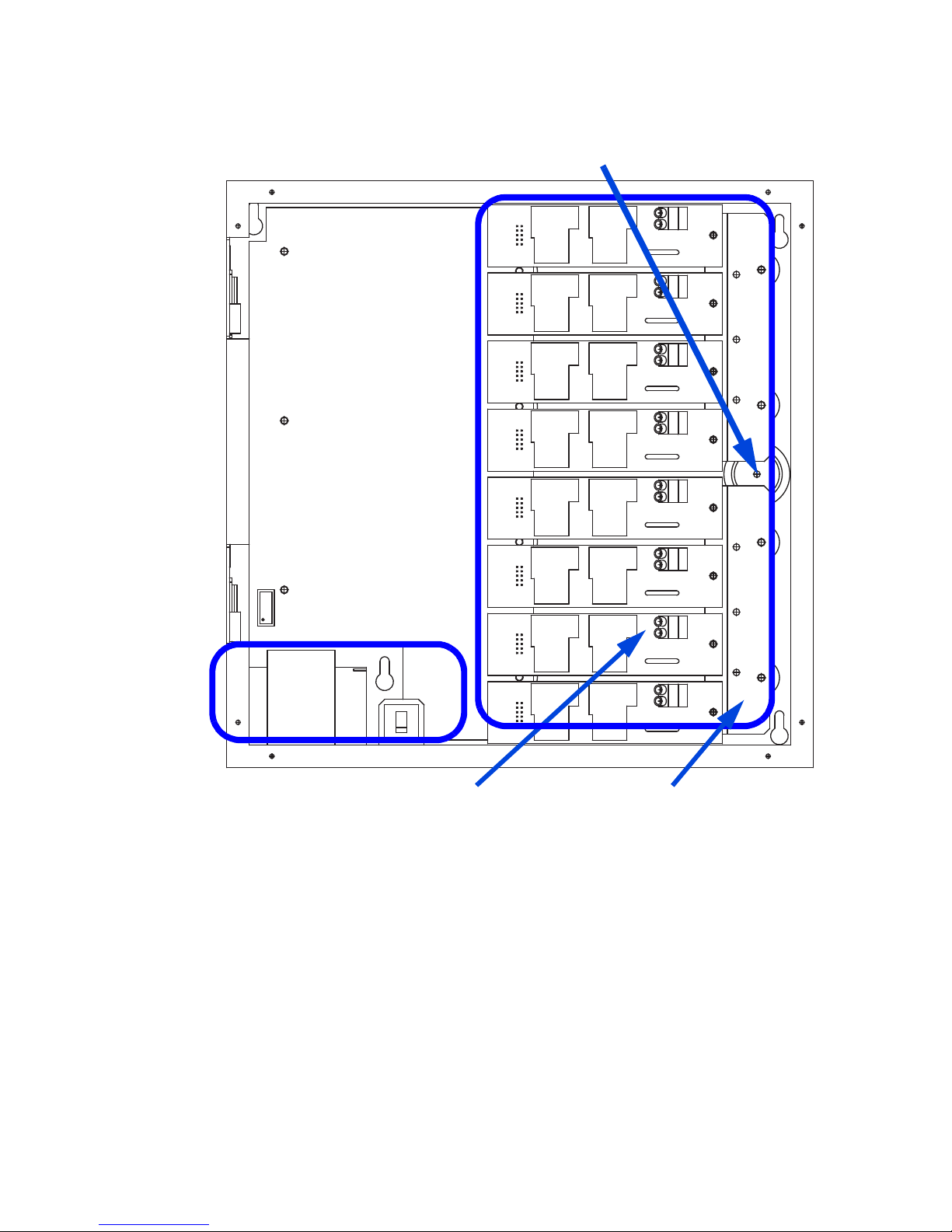
Line Voltage and Control Power Termination Overview of Power Wiring - Feed\Line Wiring
High Voltage
Connections
Transformer
Ground Point
Control Power Connections
This Area
Figure 6: EZ-MAX Plus 8 Line Voltage Wiring Areas.
Page 16
Page 20
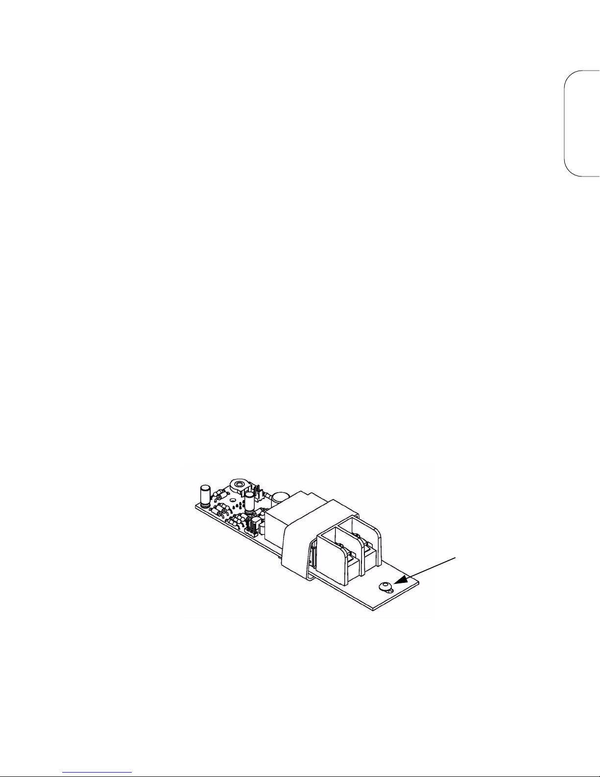
Line and Load Circuit Wiring
30-Amp Relay
Mounting Screw
EZ-MAX Plus relay cabinets have multiple relay circuits of a specific type depending on
the cabinet model. For details of the different relay types, their capacities, and
permitted wire sizes, please see “Wire Sizes and Capacities for Relays” on page 18.
Testing the Circuits
Verify that all load and feed connections have been made before you attempt to
connect any circuit to a relay. Test each circuit in the cabinet by following this
procedure:
Step 1: Turn off the breaker feeding the circuit
Step 2: Ensure that all connections and wiring between the relay cabinet and
the circuit breaker panel are complete
Step 3: Ensure that all connections and wiring between the relay cabinet and
the load are complete.
Step 4: At the relay cabinet, connect the feed(s) for relay #1 to the load for
relay #1 with a wire nut or other appropriate means.
Step 5: Turn on the circuit breaker to energize the circuit.
Step 6: Resolve any mis-wiring, shorts, etc. for the connected circuit.
Step 7: Repeat the above steps for all circuits in all relay panels for your
system. When all circuits have been tested, disconnect all Lines from
Loads and proceed to the next section.
Installing Relay Cards
On several relay cabinet models, the relays are removable. If you have one of these
cabinets and need to add or remove relay modules, please follow these instructions:
LINE VOLTAGE
Step 1: Locate the appropriate location for the relay card
Step 2: Align the connector from the relay card with the relay bus board and
gently push the two together.
Step 3: Once firmly seated, use a phillips screwdriver to tighten the mounting
screw.
EZ-MAX Plus Installation Guide Page 17
Page 21
Line Voltage and Control Power Termination Line and Load Circuit Wiring
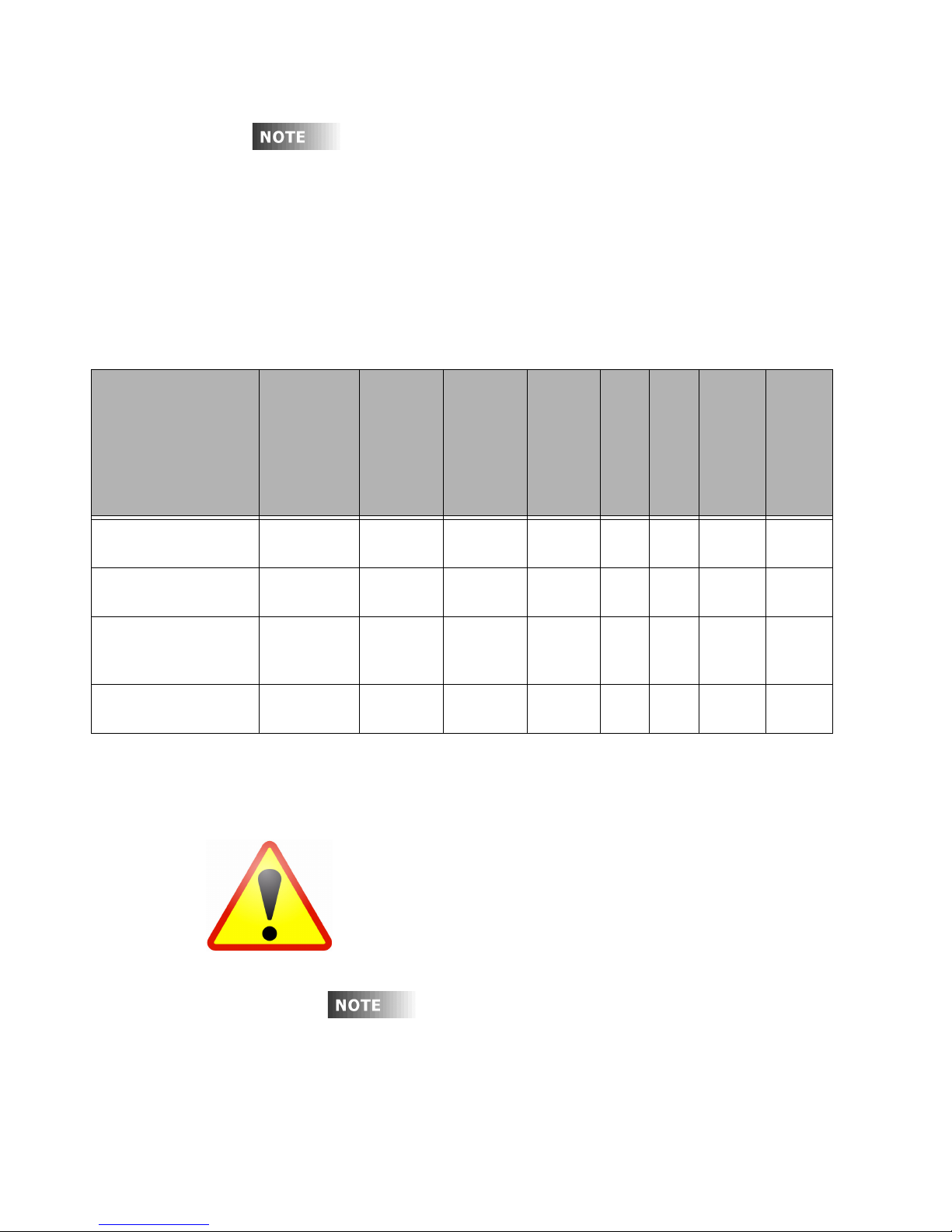
If you need to remove the installed relay cards that shipped
from the factory, remove the shipping screw located near the
connector and discard. This screw is only required for
shipping and not for installation.
MISWIRING THE RELAY MODULES WILL
CAUSE DAMAGE TO THE RELAY MODULE,
THE RELAY CABINET, AND POSSIBLY
OTHER SYSTEMS!
When driving secondary contactors, EMF may
induce significant noise which may cause some
units to reset. Installation of MOV may be
required. Please contact Leviton support for
additional details.
Wiring the Relays
Step 1: Connect the line (feed/circuit breaker) side of the circuit to the “input”
terminal(s) on the relay card.
Step 2: Connect the load side of the circuit to the "output" terminal(s) on the
relay card.
Step 3: Please note that relay card terminals accept the following wire sizes:
Relay Type
(Part #)
30-Amp Relay
(RELAY-030)
1-Pole Relay Module
(RELAY-ST2)
2-Pole Relay Module
(RELAY-2PL)
347V Relay Module
(RELAY-347)
Wire Size Wire
Type
20-8 AWG
Copper
20-6 AWG
Copper
20-6 AWG
Copper
Solid or
Stranded
Solid or
Stranded
Solid or
Stranded
Torque
Max Voltage
7 in-lbs 277V 20A 20A 1HP/
20.5 in-lbs 277V
per pole
(480V)
20.5 in-lbs 347V - 20A - 20A
Tungsten
Ballast
Rating (120V)
- 20A 2HP 20A
Motor
Rating
Rating
(120V/277V)
2HP
Figure 7: Wire Sizes and Capacities for Relays
Step 4: Circuit neutrals may follow the path of the line load conductors through
the relay panel or the line/load conductors may pass back to the
panelboard to be joined with the neutral to the load.
Inductive Ballast,
20A
HID Rating
Transformer,
Page 18
Page 22
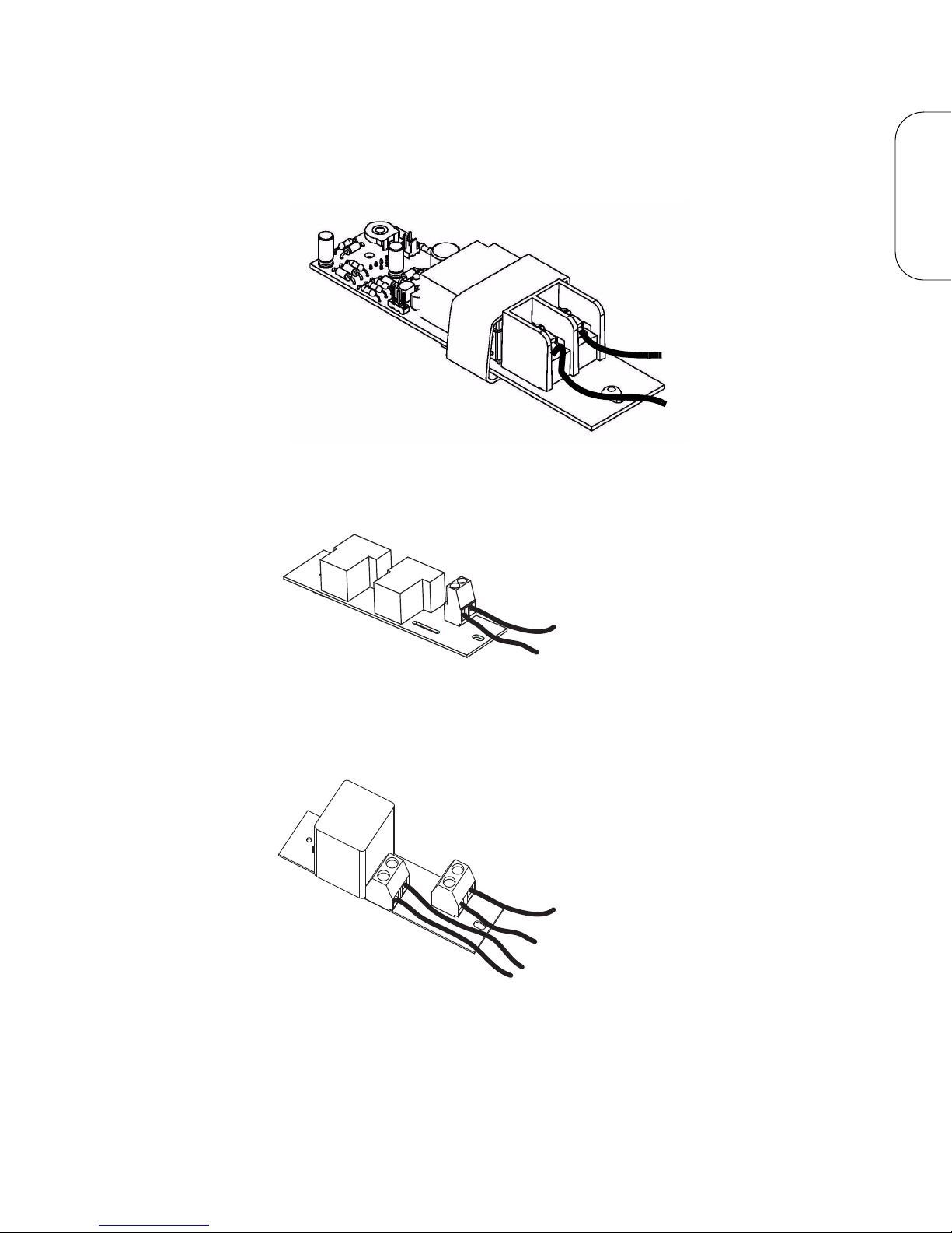
Wiring Diagrams
Load
Line
Load
Line (From Distribution Panel)
Load - Phase B
Line - Phase B
(From Distribution Panel)
Line - Phase A
(From Distribution Panel)
Load - Phase A
The diagrams on the following pages show how to wire the relay circuits.
Figure 8: Wiring Diagram for EZ-MAX Plus 30-Amp Relay Card
LINE VOLTAGE
Figure 9: Wiring Diagram for EZ-MAX Plus 1 Pole Relay Card (latching
Figure 10: Wiring Diagram for 2-Pole Relay Card
EZ-MAX Plus Installation Guide Page 19
relay card similar)
Page 23
Line Voltage and Control Power Termination Line and Load Circuit Wiring
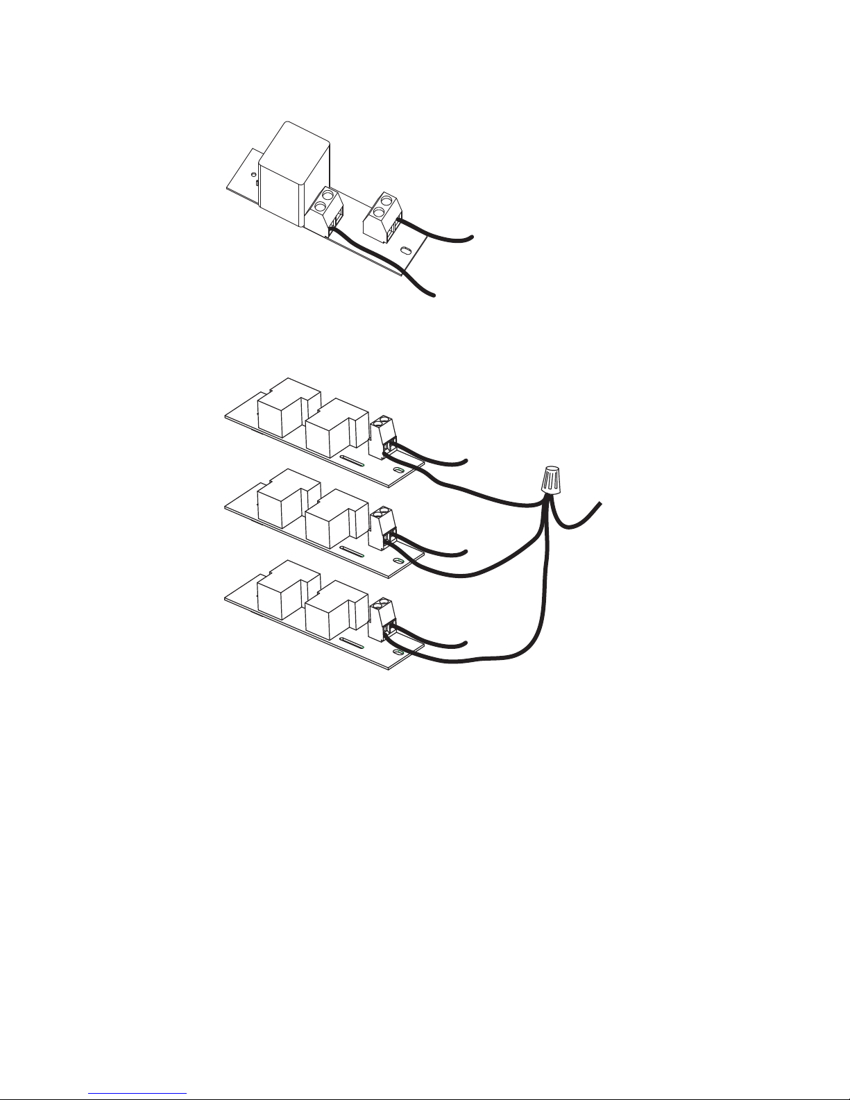
Load
Line (From Distribution Panel)
Load
Line
(From
Distribution
Panel)
Load
Load
Figure 11: Wiring Diagram for EZ-Max Plus 347 V Relay Card
Figure 12: Wiring of Multiple Relays to Common Branch Circuit Breaker
Page 20
Page 24
Control Electronics Power Wiring
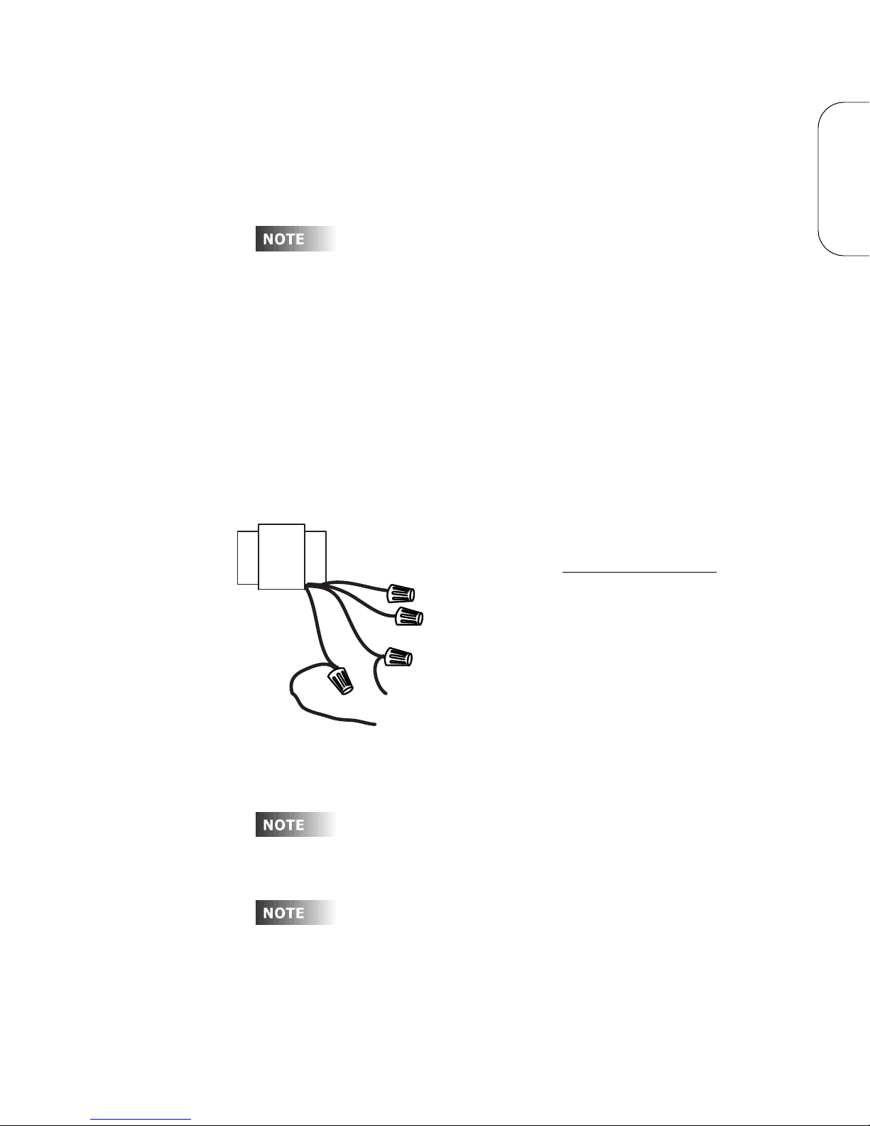
If any Emergency Circuits are fed or controlled from this
panel, it must be located electrically where fed from a UPS, a
generator, or other guaranteed source of power during
emergency and power outage situations.
Neutral -White
120V - Black
277V - Brown
347V - Orange
Multi-Tap Transformer
Dedicated Circuit
Cap (wirenut) off
unused leads
240V Wiring
240V-Orange
220V-Brown
100V-Black
The transformer leads can be found in the lower right corner
on the 8 cabinet and underneath the control module on the
right hand side of the 16/24 cabinet.
Branch circuit wiring must be a minimum of 14AWG.
Your relay cabinet requires a specific power circuit for the control electronics. Leviton
recommends that this power circuit be dedicated specifically and used only for power
to the control electronics.
To connect your relay cabinet’s control electronics to power, please follow these steps:
Step 1: Connect the relay cabinet to the circuit panel using conduit.
Step 2: Remove all cuttings and dirt.
Step 3: Run a dedicated circuit from the circuit panel or distribution panel to
the relay panel for the control electronics. Make sure the power is off at
the breaker.
Step 4: Wire the circuit as shown in the following figure:
LINE VOLTAGE
Figure 13: EZ-MAX Plus 16/24 Relay Cabinets Control Electronics Power
Step 5: Connect the circuit’s ground wire to the relay cabinet.
Step 6: Keep the circuit off until all wires are terminated, tested, and double
EZ-MAX Plus Installation Guide Page 21
checked.
Page 25

Line Voltage and Control Power Termination Control Electronics Power Wiring
Page 22
Page 26

Low Voltage
Page 27

Page 24
Page 28

Low Voltage Control Wiring
Each product (and in some cases each model of a
product) has a slightly different layout at the terminal
blocks. The specific function of each terminal is labeled on
the circuit board adjacent to the terminal blocks. When
wiring the inputs, verify that you are connecting the
correct wire to the correct terminal based on function,
even if it deviates from what is shown in this
documentation. Contact our technical services
department with any further questions.
Once the power wiring has been completed, you can begin the control wiring. Control
wiring can be divided into two categories: analog and digital. Remote relay panels
only support analog control inputs.
Control Overview
The Leviton EZ-MAX Plus relay products are simple yet powerful, and can be operated
by multiple control sources. Control input to a relay cabinet can be any combination of
the following:
• Low Voltage momentary or maintained through a discrete input.
• Momentary 2-Pole On/Off through a discrete input.
• Photocell 0-10VDC or Switched through a discrete input.
• Occupancy sensor through a discrete input.
• Dry Contacts through a discrete input.
• Digital control inputs (See “Wiring the Phoenix Connector” on page 40).
Please see “Product Specifications and Capabilities Chart” on page 3 for more
information on the quantity and types of inputs available for each cabinet. All inputs
(except network inputs) support every type as shown above.
The specific wiring requirements for each input type are discussed on the following
pages.
LOW VOLTAGE
EZ-MAX Plus Installation Guide Page 25
Page 29

Low Voltage Control Wiring Control Overview
Control Wiring Termination
This section gives instructions for terminating all types of low voltage inputs.
• Leviton recommends minimum 18AWG stranded wire for all low voltage wiring.
• Terminate all control wiring directly to the terminal blocks on the printed circuit
board. Use a small 1/8-in. flat screwdriver on these terminals.
• Terminal blocks are 2-part terminals and can be removed for ease of termination.
When reinstalling them make sure they are plugged in the correct direction
according to the way they were wired.
• All control wiring shall be considered Class 2.
• Use control wire type and size as specified below:
Connector Type Wire Size and type Torque
Switch Inputs 14-24 AWG, Stranded 2 in-lb.
Figure 14: Control Wire Type and Size
Input Trigger-What Determines an “ON”
Each of the low voltage inputs can be triggered by either the supply of voltage or a
connection to common. When voltage is supplied to an input indicating a change of
state, we call this “pulling up the input” or “active high.” When a connection to
common triggers the input, causing a change of state, we call this “pulling down the
input” or “active low.”
By default, all inputs are active high (that is receiving voltage to trigger). Active High
inputs must not exceed a nominal +24VDC and must be above +9vdc. Active Low
inputs must connect to the same common at the same potential as the cabinet.
To change from an active high input to an active low input, the polarity jumper must
change position. There are several illustrations which show the location of these
jumpers.
Input Power Requirements
The relay cabinet has a finite amount of power which it can supply to connected
devices. This topic is discussed in detail in “Power Considerations for Control Systems”
in Appendix A. Please make sure that you do not exceed the amount of available
peripheral power, or damage to your relay cabinet or connected devices may occur.
Page 26
Page 30

General Requirements for Connecting any Device to Low Voltage
Inputs
Step 1: Connect leads per wiring diagram as illustrated in the figures on the
following pages.
Step 2: Twist strands of each lead tightly (making sure that there are no stray
strands) and push firmly into appropriate plug connector location.
Step 3: Tighten the screws on the plug connector—making sure that no bare
conductor is showing.
Step 4: Plug the connector back onto the control module with the screws facing
the front and the wires coming out of the connector toward the top of
the cabinet.
LOW VOLTAGE
EZ-MAX Plus Installation Guide Page 27
Page 31

Low Voltage Control Wiring Control Overview
Page 28
Page 32
Low Voltage Switches
IN
Switch Inputs and DMX Connector-
Wire Range #14 - #24 AWG
Torque2 LB-IN
Luma-Net Connector
Wire Range #12 - #24 AWG
Torque 5 LB-IN
ANALOG/SWITCH INPUT/OUTPUTS TB 1-12*
IN
+24V
OUT
IN
COM
OUT
+24V
COM
IN
OUT
+24V
COM
+24V
IN
OUT
COM
OUT
+24V
COM
IN
OUT
+24V
COM
COM
OUT
IN
COM
IN
OUT
+24V
IN
OUT
+24V
COM
+24V
IN
COM
IN
OUT
+24V
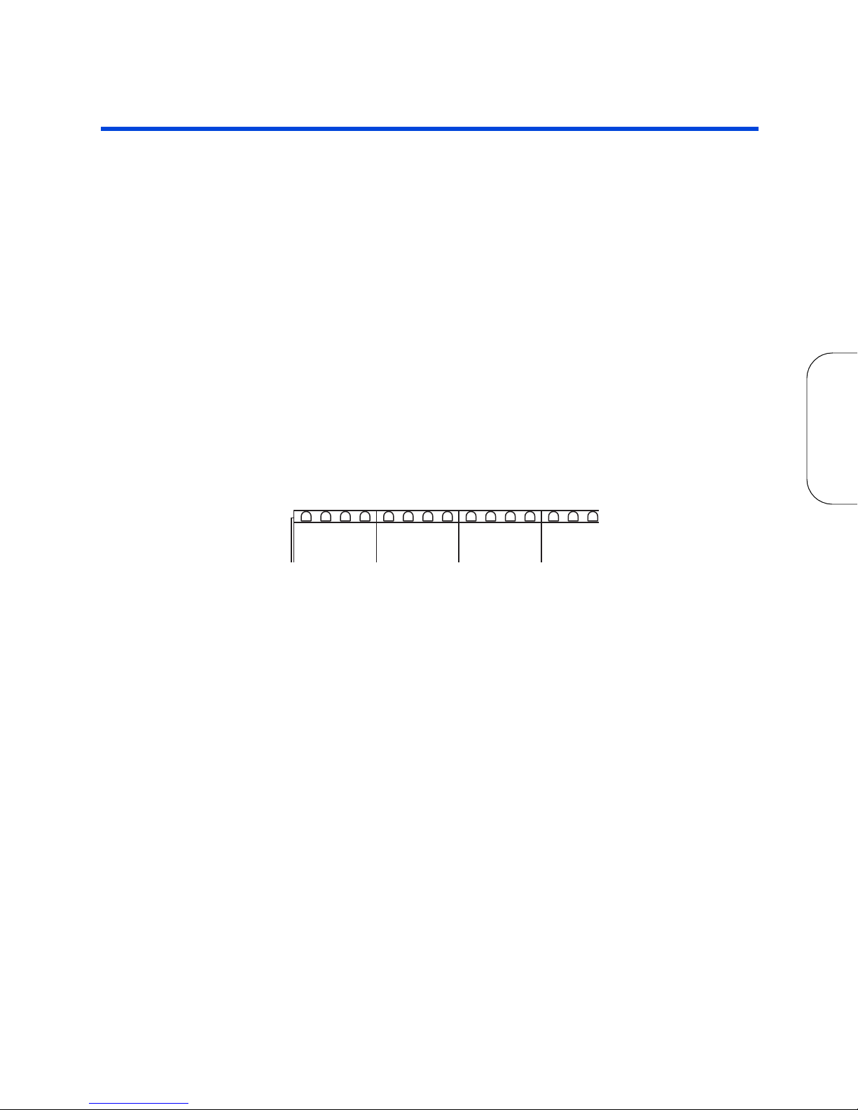
EZ-MAX Plus relay panels support a variety of low voltage switch types such as:
• Momentary: provides momentary contacts, triggering alternating On/Off
actions.
• Maintained: triggers On action when connection is made, Off action when
removed.
• Momentary On/Off with On & Off terminals provided: provides momentary
connection to the “On” terminal to trigger an On action, momentary connection to
the “Off”. Used with single pole double throw center off (SPDT-CO) switches.
• Momentary On/Off with only “IN” or “ON” terminal: used with 2-pole
center off switches and must be used in conjunction with compatible switch input
kits to convert from a 1 terminal to a 2 terminal input.
Each Input has a multi-position screw terminal with various positions. The terminal
can be pulled off its base for ease of wiring. One possible pinout is shown below.
Please remember to verify the function of each pin as labeled on the product with the
device being wired to ensure that it is wired correctly.
.
LOW VOLTAGE
Figure 15: Low voltage terminal layout, 8/16/24 relay cabinets
EZ-MAX Plus Installation Guide Page 29
Page 33

Low Voltage Switches
Typical terminal designations for all products are shown below. Please confirm the
function of each pin on your device with the labeling on the circuit board prior to any
termination.
Pin Label Function
+24V Supplies +24Vdc power to devices, usually
unregulated
COM Connection to DC Common of the cabinet
IN Switch Input or signal from device. Usually
expecting +V to trigger.
OUT Used for connection to device LED indicating on/off
state of that input. Connects to common when on,
floats when off. (Max 0.04A)
LED Used for connection to device LED indicating on/off
state of that input. Connects to common when on,
“floats” when off. (Max 0.04A)
ON Usually can be configured identically to the IN
terminal but can be configured as Momentary ON
input only
OFF Momentary OFF input only
Figure 16: Discrete input terminal labels and their meanings —applies to all
Leviton products
By default, the “IN” or the “ON” terminal is expecting +V to trigger as would be typical
with many styles of low voltage switches. If a connection to common is required, it
requires some jumper and software reconfiguration. For more information on this
topic, please see “Input Trigger-What Determines an “ON”” on page 26.
Connecting to a Low Voltage Input
Step 1: Strip each wire from your device and tightly twist the wires together.
Step 2: Insert the wires from the device into the connector on the relay cabinet
in the appropriate location.
Page 30
Page 34
Switch
Inputs
EMERGENCY - TB17*
ETHERNET
OUT
JP9
RELAY 8
RELAY 7
RELAY 6
AC1
18 VAC IN
AC2
(OPTIONAL)
SERVICE ONLY
INTERFACE
J1
LCD
IN
S8
MODULE
MODEM
MODULE
OR
TB1
+24V
ON
RELAY 5
RELAY 4
RELAY 3
RELAY 2
RESET
JUMPER OFF IS DEFAULT
JUMPER ON PULLS INPUT HIGH
JP41
ETHERNET/MODEM
ALL RIGHTS RESREVED WORLDWIDE
OX-70129-00-00-02 BASIC
OX-70129-00-00-01 NETWORK
OUT
SELECTOR S1 THRU S8
ANALOG/SWITCH I/O*
COM
+24V
+24V
COM
OUT
IN
IN
1
TB8
S7
TB7
S6
+24V
COM
+24V
COM
OUT
IN
S5
TB6
}
TB5
S1
LEVITON ASSEMBLY
C 2004 LEVITON MFG. CO.
RELAY
NO1
EMERGENCY
NORMAL
COM
TB3
OUT
COM
+24V
OUT
+24V
IN
IN
S4
TB4
S3
OUT
COM
+24V
OUT
IN
IN
S2
TB2
COM1
S14
S1
OFF
HEARTBEAT-R
5V POWER
ETH/MODEM
LUMANET
HEARTBEAT-C
EMERGENCY
D3 CAN1
D12
D27
D1
D8 CAN2
D4
D2
D6D7DMX
TB15
CAN 1
TERM
JP21
TERM
DMX
NC1
JP15
TERM
CAN 2
TB16
JP35
1 1
RELAY 1
LUMA-NET
SELECT
VOLTAGE
LUMA-NET
LUMA-NET
+12V
COM
TB17
COM.
EMERG.
J3
JP13
SWITCH
BYPASS
TERM
R+
R-
TB9
TRM
+V
COM
USB
TB9**
TB11
31
TB10
+24V
D-
COM
LCK
D+
TB13
1 1
MASTER/
SLAVE
DMX 512
TB10*
Switch Inputs and DMX ConnectorWire Range #14 - #24 AWG
Torque2 LB-IN
Luma-Net Connector
Wire Range #12 - #24 AWG
Torque 5 LB-IN
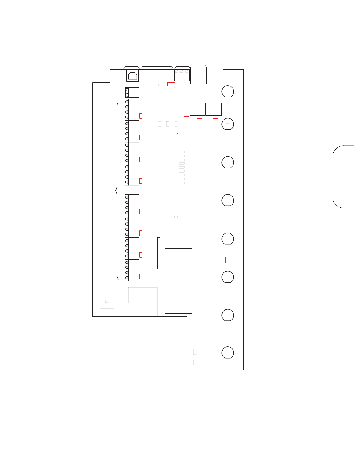
Figure 17: Inside layout of an EZ-MAX 8-Relay Cabinet.
Step 3: Tighten the terminal screw, and repeat for all wires from the device.
LOW VOLTAGE
EZ-MAX Plus Installation Guide Page 31
Page 35

Low Voltage Switches
Step 4: Plug the terminal block back into the cabinet with the screws facing
toward you and the wires exiting toward the side or top of the cabinet.
Alternatively, the connector can be inserted with the screws parallel to
the circuit board and the wires exiting toward you.
Step 5: Verify that the wires land on the correct terminals.
Page 32
Page 36
Occupancy Sensors
).6#/-
%ODFN&RPPRQ
5HG9
%OXH6LJQDO
7HUPLQDORUGHUIXQFWLRQPD\GLIIHUIURP
WKDWVKRZQ&RQ¿UPRQFDELQHWFLUFXLW
ERDUGRU,'ODEHO
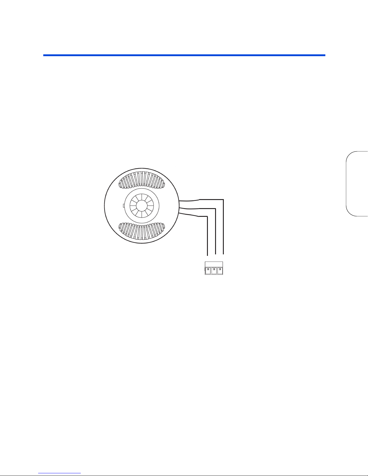
One of the control input types that your relay cabinet can accept is Occupancy
Sensors. When using an occupancy sensor, the cabinet is expecting a DC voltage
between +9V & +24V to trigger an occupied state, or a floating input to indicate an
unoccupied state. The specific function of what happens in each of these states is set
via software configuration. This section only deals with connecting your Occupancy
Sensor to your relay cabinet. See the EZ-Max Plus Programmer’s Guide for more
information on programming your inputs.
Occupancy Sensor Wiring
Step 1: Connect leads per wiring diagram below.
LOW VOLTAGE
Figure 18: Occupancy Sensor Termination using Dedicated Occ Sensor
Terminal
Step 2: Twist strands of each lead tightly (making sure that there are no stray
strands) and push firmly into appropriate plug connector location.
Step 3: Tighten the screws on the plug connector making sure that no bare
conductor is showing.
Step 4: Plug the connector back onto the control module.
Step 5: Verify that the wires from the Occupancy Sensors are connected to the
correct terminals in the cabinet.
EZ-MAX Plus Installation Guide Page 33
Page 37

Occupancy Sensors Occupancy Sensor Wiring
Page 34
Page 38
Photocells
IN +V COM
Terminal order/function may differ from
that shown. Confi rm on cabinet circuit
board or I.D. label.
IN +V COM
Common
(DC Ground)
Power (+24VDC)
Control Signal
(+0-10VDC)
PhotoCell
Terminal order/function may differ from
that shown. Confi rm on cabinet circuit
board or I.D. label.
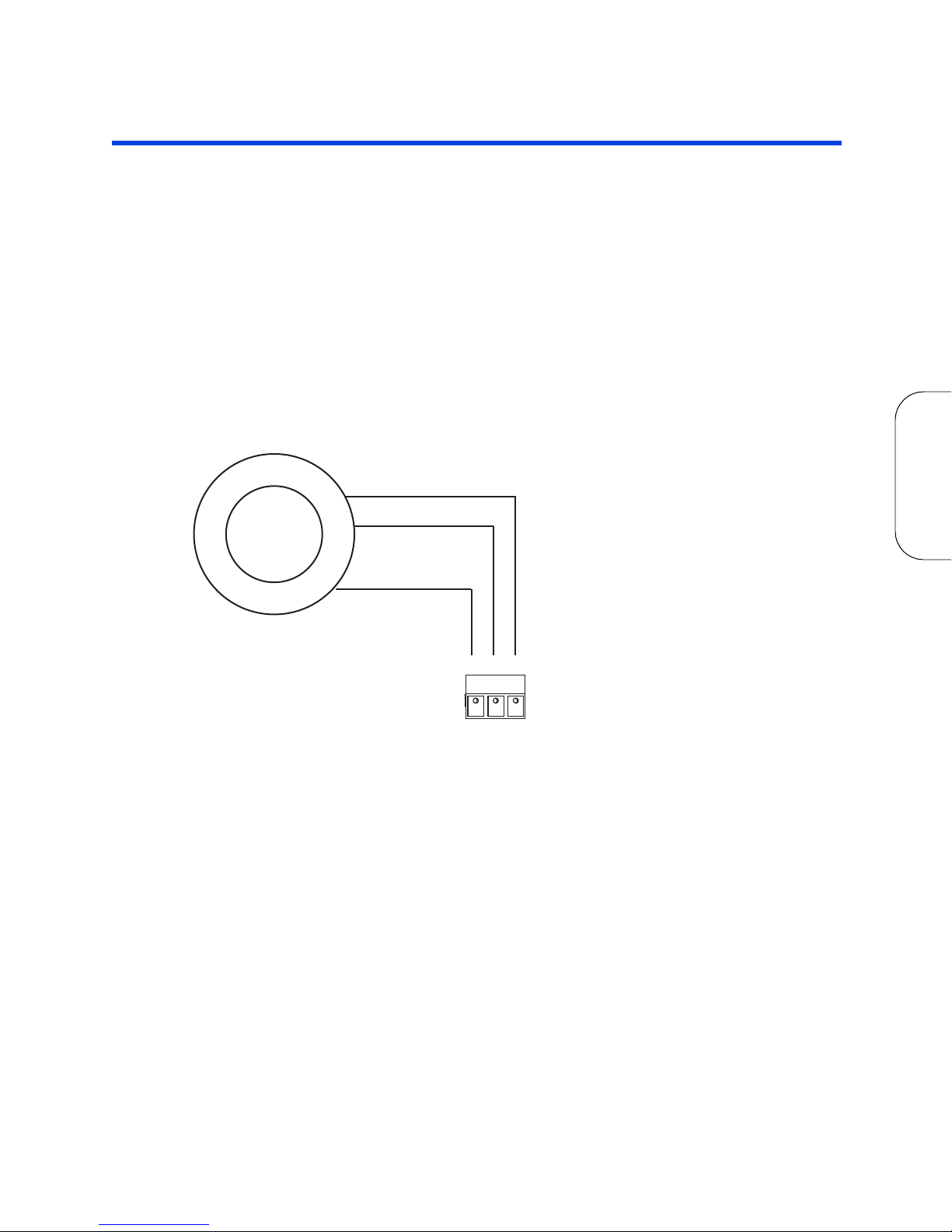
The relay cabinet is capable of supporting the following types of photocells:
• Switched Photocell (On/Off, trigger point set at photocell).
• 0-10V Photocell.
The configuration and behavior of your photocell is set via software (see the EZ-MAX
Plus Programmer’s Guide for details). This section only covers installation.
Photocell Wiring
Step 1: Connect leads per wiring diagram as illustrated in one of the following
figures:
LOW VOLTAGE
Figure 19: 0-10VDC Photocell Wiring
EZ-MAX Plus Installation Guide Page 35
Page 39

Photocells Photocell Wiring
IN +V COM
Switch Leg
PhotoCell
Switch Leg
AC Power
Note: Switch Legs must be
completly isolated from
Photocell AC power and
should be connected to
either side of the switching
relay at the photocell.
Note: If your switching photocell requires +24VDC power,
this power can be sourced from
the cabinet just like a 0-10VDC
photocell. The switch legs
should still be between COM &
IN terminals
Figure 20: Switching Photocell
Step 2: Twist strands of each lead tightly (making sure that there are no stray
strands) and push firmly into appropriate plug connector location.
Step 3: Tighten the screws on the plug connector making sure that no bare
conductor is showing.
Step 4: Plug the connector back onto the control module with the screws facing
the front and the wires coming out of the connector toward the top of
the cabinet.
Step 5: If using a switched photocell, make sure that the jumper below the
connector is in the “ON” position.
Page 36
Page 40

Digital
Page 41

Page 38
Page 42
Luma-Net III
Luma-Net is Leviton’s proprietary digital architectural lighting control protocol.
Luma-Net can be used for the following items:
• Optional Communication and control by Dimensions 8000 control stations and
• Optional Communication and control by Dimensions 4200 control stations and
Wiring Specifications
Maximum End to End Run Length 2,000 feet
accessories.
accessories.
Specification Description
Maximum number of controlled channels
per subnet
Maximum number of nodes per subnet on
the network
Network Topology Daisy-Chain
Interconnection Method Terminal
Wiring Specifics (1) Twisted Data Pair plus a common
Supported Voltage +12-24Vdc
Minimum voltages for node functionality varies depending on node type, usually
Recommended Wire
(includes data and power pair)
Alternate Approved Wire Belden 9729,9829,8102,9841,
(when used with a D400 or D800 station)
required for digital communication signal
Node power requires additional power
Belden 1502P (Plenum)
2,048
255
wiring
+10Vdc
Belden 1502R
89729,88102
Alpha 6222C, 6412
DIGITAL
Network Protocol Leviton Luma-Net
Conflicting or Multiple Control Message
Mitigation Strategy
Termination Requirements Terminate at both ends of control run
EZ-MAX Plus Installation Guide Page 39
on RS-485
Last Action Takes Precedence
Data- to common with 100-120ohm
resistor
Page 43
Luma-Net III Wiring Specifications
REM+
REM -
COM
TERM
LOCK
+V
1
2
3
4
5
6
Up
to
1 #12AWG
2#12AWG
2#12AWG
Up to
1 #12AWG
Drain/Shield - Insulated and tied together
(Ground at one point onlyprobably an end)
Red
(+V )
Black (Common)
5
6
1
2
3
4
Phoenix/Luma-Net Connector
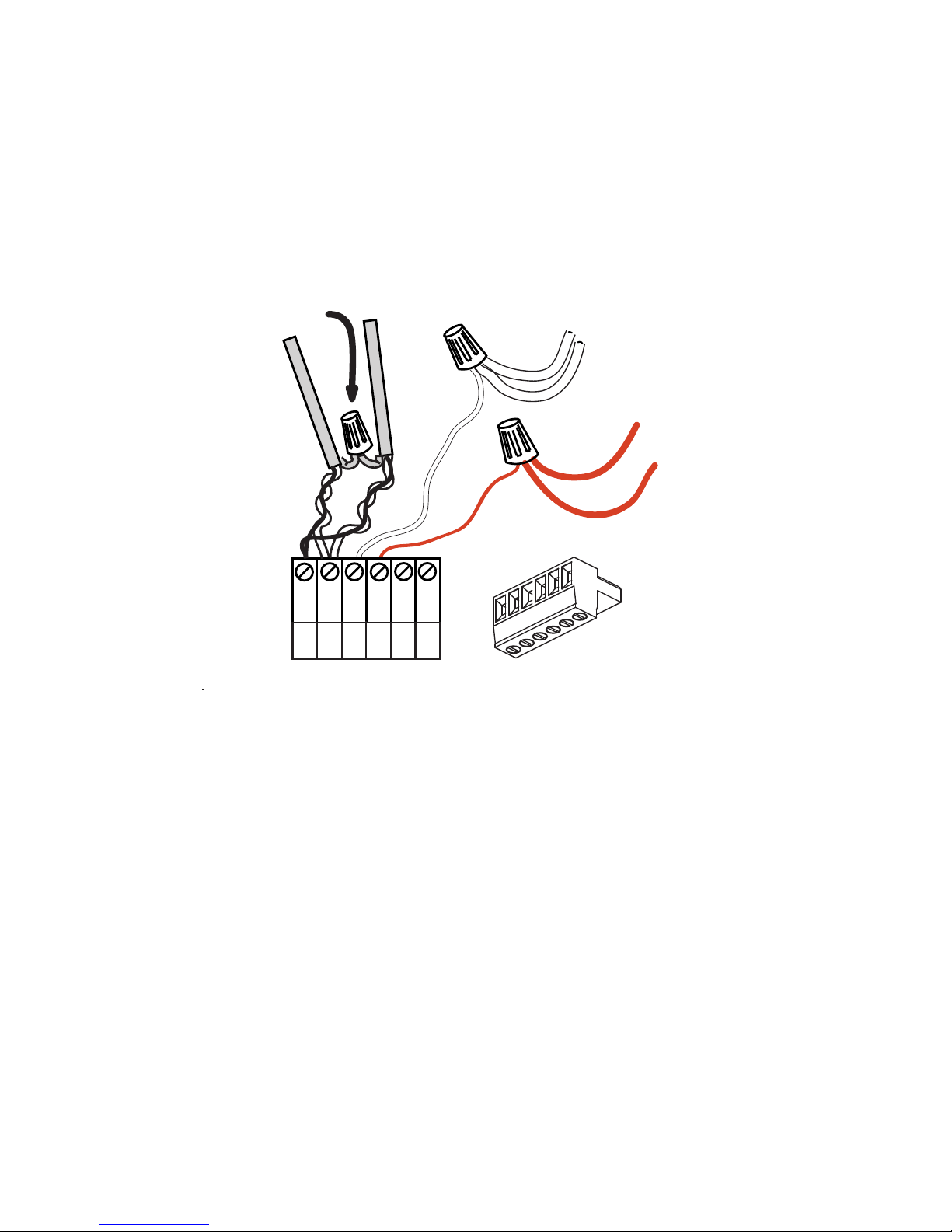
Wiring the Phoenix Connector
Step 1: Connect leads per the wiring diagram below.
Step 2: Twist strands of each lead tightly (making sure that there are no stray
strands) and push firmly into appropriate plug connector location.
Step 3: Tighten the screws on the plug connector—making sure that no bare
conductor is showing.
Step 4: Tie the Drain/Shield wires together and insulate using a small piece of
heat shrink tubing.
Page 40
Page 44
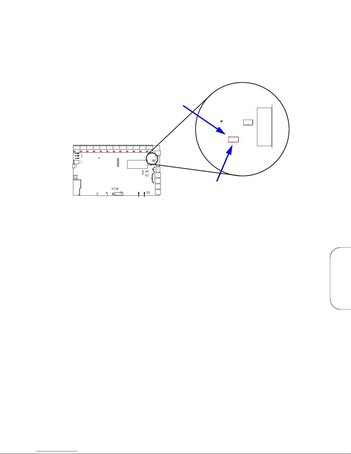
Step 5: Install termination jumpers as required. Termination jumpers are
IN
COMMON
NC
NO
SERVICE
J15
KEYBOARD/LCD
RESET
ONLY
J7
RELAY BUS BOARD
J16
KEYBOARD/LCD
(ALT)
J13
JP11
AC1
AC2
18 VAC IN
TERM
TB16
1
TB19
1
1
TB15
COM
ETHERNET/MODEM
DMX 512
SELECT
VOLTAGE INPUT
LUMA-NET TB13**
+24V
}
ALL RIGHTS RESERVED WORLDWIDE
ANALOG/SWITCH I/O*
(OPTIONAL)
USB TYPE B
J6
SWITCH BOARD
EMERGENCY
INPUT - TB21 *
EMERGENCY
EMERG
COM
RELAY
SELECTOR S1 THRU S12
C 2004 LEVITON MFG. CO.
IN
+24V
OUTINCOM
OUT
+24V
TB1S1TB2
S2
COMINOUT
+24V
COM
TB3
S3
+24V
TB5
IN
OUT
COM
OUT
+24V
TB4
S4
S5
COMINOUT
+24V
COM
TB6
S6
JUMPER ON PULLS INPUT HIGH
MODEM MODULE
ETHERNET MODULE
5V POWER
OX-70121-00-00-02 SLAVE
OX-70121-00-00-01 MASTER
JUMPER OFF IS DEFAULT
ETH/MODEM
HEARTBEAT-C
LUMANET
EMERGENCY
CAN1
CAN2
DMX
(OPTIONAL)
MASTER/SLAVE
TB17
SERIAL
TX
INPUT
RX
AUX.
COM
JP9 TERM
JP7
1
TB 14**
TERM
OR
JP6
JP36
COM
OUT
S8
TB8
IN
COMINOUT
+24V
TB7
S7
IN
OUT
+24V
COM
+24V
TB9
S9
OUT
S11
TB11
IN
COMINOUT
+24V
TB10
S10
IN
OUT
+24V
COM
+24V
TB12
S12
JP30
1
TB20
DD+
COM
123
REM-
TERM
+12V
LOCK
TERM
COM
+V
REM+
1
DMX 512
SELECT
VOLTAGE INPUT
LUMA-NET TB13**
+24V
TB 14**
JP6
JP36
JP30
DD+
COM
123
REM-
TERM
+12V
LOCK
TERM
COM
+V
REM+
1
Termination Jumper Location
(actual location in your cabinet may vary)
Jumper must be in +24V position to
power digital stations
required at the two ends of the Luma-Net run. The termination can be
accomplished on the Luma-Net connector with a jumper wire as shown
below. Termination can also be accomplished on the control board by
jumpering the 2 pin header to the left of the Luma-Net connector.
Figure 21: Typical termination jumper location
EZ-MAX Plus Installation Guide Page 41
DIGITAL
Page 45

Luma-Net III Wiring Specifications
Page 42
Page 46

Emergency
Page 47

Page 44
Page 48

Emergency
Extended information available in the EZ-Max
Plus Programmer’s Guide.
PG
The emergency input is set from the factory as a level 2
priority, only overridable by the internal bypass switch.
Inputs and Outputs
The control card has both an emergency input and output. The input can be driven by
a contact closure such as one from a fire alarm or by a low voltage signal capable of
sinking 5 mA (3 - 5 volts is emergency off and 0 - 2 volts is emergency on).
Emergency output has a common contact and both NO and NC contacts. In the nonemergency state, the NO contact is closed. If the emergency input is activated
(closed) or if power is interrupted to the relay cabinet, the NC contact will be closed.
If it is desirable, the output of one cabinet can be connected to input of another
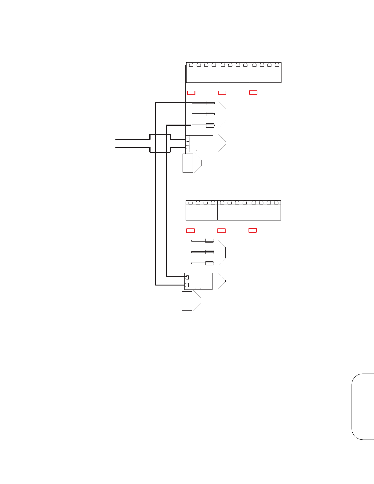
cabinet. In this case, connect the commons of both input and output together and
connect the NC output contact to the emergency signal on the input connector as
shown in the figures on the following pages.
Each relay can be configured to go on,
in an emergency state.
If the emergency input changes from closed to open (low to high), the relays will
return to their previous states.
off
or to
no change
via the setup menu when
EZ-MAX Plus Installation Guide Page 45
EMERGENCY
Page 49
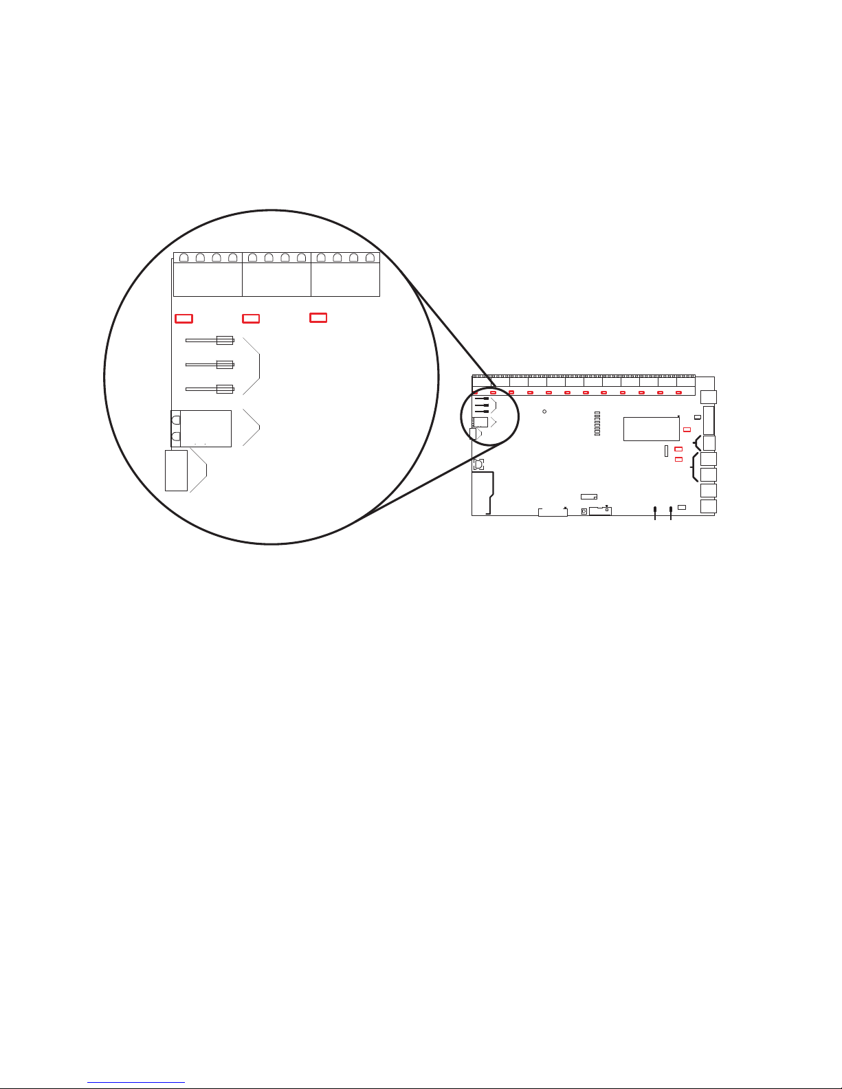
Emergency Terminal Locations
IN
COMMON
NC
NO
SERVICE
J15
KEYBOARD/LCD
RESET
ONLY
J7
RELAY BUS BOARD
J16
KEYBOARD/LCD
(ALT)
J13
JP11
AC1
AC2
18 VAC IN
TERM
TB16
1
TB19
1
1
TB15
COM
ETHERNET/MODEM
DMX 512
SELECT
VOLTAGE INPUT
LUMA-NET TB13**
+24V
}
ALL RIGHTS RESERVED WORLDWIDE
ANALOG/SWITCH I/O*
(OPTIONAL)
USB TYPE B
J6
SWITCH BOARD
EMERGENCY
INPUT - TB21 *
EMERGENCY
EMERG
COM
RELAY
SELECTOR S1 THRU S12
C 2004 LEVITON MFG. CO.
IN
+24V
OUTINCOM
OUT
+24V
TB1S1TB2
S2
COMINOUT
+24V
COM
TB3
S3
+24V
TB5
IN
OUT
COM
OUT
+24V
TB4
S4
S5
COMINOUT
+24V
COM
TB6
S6
JUMPER ON PULLS INPUT HIGH
MODEM MODULE
ETHERNET MODULE
5V POWER
OX-70121-00-00-02 SLAVE
OX-70121-00-00-01 MASTER
JUMPER OFF IS DEFAULT
ETH/MODEM
HEARTBEAT-C
LUMANET
EMERGENCY
CAN1
CAN2
DMX
(OPTIONAL)
MASTER/SLAVE
TB17
SERIAL
TX
INPUT
RX
AUX.
COM
JP9 TERM
JP7
1
TB 14**
TERM
OR
JP6
JP36
COM
OUT
S8
TB8
IN
COMINOUT
+24V
TB7
S7
IN
OUT
+24V
COM
+24V
TB9
S9
OUT
S11
TB11
IN
COMINOUT
+24V
TB10
S10
IN
OUT
+24V
COM
+24V
TB12
S12
JP30
1
TB20
DD+
COM
123
REM-
TERM
+12V
LOCK
TERM
COM
+V
REM+
1
IN
COMMON
NC
NO
J15
EMERGENCY
INPUT - TB21 *
EMERGENCY
EMERG
COM
RELAY (OUTPUT)
+24V
OUT
IN
COM
OUT
+24V
TB1
S1
TB2
S2
COM
IN
OUT
+24V
COM
TB3
S3
Terminal Locations
Emergency terminal locations for the EZ-Max Plus 8 and 16/24 relay cabinets are
shown.
Figure 22: Emergency Input and Output Connectors 16/24 relay cabinets
Page 46
Page 50
IN
COMMON
NC
NO
J15
EMERGENCY
INPUT - TB21 *
EMERGENCY
EMERG
COM
RELAY (OUTPUT)
+24V
OUT
IN
COM
OUT
+24V
TB1
S1
TB2
S2
COM
IN
OUT
+24V
COM
TB3
S3
IN
COMMON
NC
NO
J15
EMERGENCY
INPUT - TB21 *
EMERGENCY
EMERG
COM
RELAY (OUTPUT)
+24V
OUT
IN
COM
OUT
+24V
TB1
S1
TB2
S2
COM
IN
OUT
+24V
COM
TB3
S3
Cabinet
One
Cabinet
Two
From
contact closure
or other source
(Upper left hand corner of control module shown)
Figure 23: Wiring Diagram for 16/24 relay cabinets showing (2)
EZ-MAX Plus Installation Guide Page 47
interconnected Emergency Cabinets.
EMERGENCY
Page 51

Emergency Terminal Locations
Page 48
Page 52

Appendix A
Power-Up and Installation Verification
Checklist
Prior to the application of power to your relay cabinet, all of the following steps must
have been successfully executed.
Inspect each relay load wiring for incomplete termination
Inspect each relay’s load wiring for terminals not completely tightened
With each relay in the “off” position, check for voltage between the Line & Load
terminals; there should be none.
Inspect all low voltage wiring and ensure that it is complete.
Inspect control power wiring, ensure that it is complete.
Confirm that any unused supply wires on the control power transformer have
been suitably capped.
Confirm that all connected load wiring between the relay panel and it’s load has
been completed.
Confirm that wiring between the cabinet and all low voltage devices has been
completed.
Apply power to the cabinet.
Confirm that the cabinet boots properly and returns to the status “normal” screen.
Set the Time & Date from the menu.
Update system software with the latest available software from the website, if
appropriate.
Proceed to panel programming.
EZ-MAX Plus Installation Guide Page A-1
Page 53

Power-Up and Installation Verification Checklist
Page A-2
Page 54

Appendix B
This section of the document contains information that
applies to many Leviton products and is not necessarily
limited to the product that is primarily included in this
manual. There may be information in this chapter which is
not relevant to your particular installation. If you have
questions about ANY information contained in this manual,
please immediately contact our Technical Services
Department prior to proceeding with installation.
Power Considerations for Control
Systems
The control system should be carefully planned to take these important issues into
consideration:
• Power Supply for connected devices.
• Wire Size for Power Runs.
On systems where full factory drawings have been provided, our Applications
Engineering department has already managed these calculations for you so you only
need to follow the instructions on the system drawings. However, on any installation
where factory drawings were not provided, the information contained within this
guide must be followed to ensure that all of your devices operate properly and
without failures or complete in-operability.
Terminology
Please review these definitions that are used throughout this section:
• Power Supply or Supply: references a device that supplies power to other
devices.
• Power Control Device (PCD): refers to a device that controls power. The
EZ-MAX Plus relay panel is an example of a devices in the Leviton product line
that controls power. PCD’s supply a certain amount of power to connected low
voltage control devices.
• Control Devices or Low Voltage Control Devices or Device: these terms all
refer to control devices that connect to a Power Control Device (PCD). These
devices could be simple low voltage switches, Occupancy Sensors, or D8000
control stations.
• Luma-Net: is one of our network lighting control protocols. Luma-Net is an
RS-485- based control protocol used by EZ-MAX PLus Digital Control Stations,
D8000 and D4200 control devices. Many of our PCD (Power Control Device)
products have a direct data connection for a Luma-Net device. All Luma-Net
Control Devices require power in one form or another. This power generally
accompanies the data wires.
EZ-MAX Plus Installation Guide Page B-1
• Unit Load: one (1) Unit load is defined as 25mA, or 0.025A. It is an arbitrary
definition by Leviton and was created to simplify power calculations.
Page 55

Power Considerations for Control Systems
One Unit Load = 25mA = .025A
Control Station A Unit Load
X
Quantity of Station A's attached
+
Same formula
for any other attached
control Station
Control Station B Unit Load
X
Quantity of Station B's attached
<
+
Power Supply's
Available Unit Load
The sum of all devices connected to all power output
terminals can not exceed the Maximum number of Unit Loads
available in the PCD or supply.
Power Requirements and Maximum Run Length
Each Control Device used in your system has a different load (draw) and each PCD
can support a different total load (supply.) There are logical steps for determining the
total load of your network and verifying that the supply is sufficient:
Step 1: Determine the maximum available current of your supply, be it a PCD or
other Power Supply. Convert this to the maximum number of Unit Loads
if necessary.
Step 2: Calculate the sum required load of each Control Device, expressed in
unit loads
Step 3: Verify that the Sum from Step 2 <= the maximum available power from
your supply in Step 1.
If this verification fails (the Sum of required loads is > than the available supply) you
can either use an external power supply or reduce the number of control devices. Or,
contact our Technical Services department for help.
Figure B-1: Load Rating Verification Formula
Power Control Devices - Available Supply Current
The EZ-MAX Plus cabinets are designed to be able to power external control loads
from the internal power supply.
Page B-2
Page 56

Control Device Loads
Control Devices Unit Load
@12VDC
Unit Load
@24VDC
Station Type Unit Load
D4200 LCD 5 2 EZ-MAX Plus Digital
Switch, 1 Button
D4200 Entry (Button), 2 1 EZ-MAX Plus Digital
Switch, 2 Buttons
D4200 Room Combine
Station
3 1 Z-AX Digital Switch, 3
Buttons
D4200 Remote I/R 2 1 EZ-MAX Plus Digital
Sw., 4 Buttons
Luma-Net Hub 6 3 EZ-MAX Plus Digital
Switch, 5 Button
D8000 LCD 3 2 EZ-MAX Plus Digital
Switch, 6 Button
D8000 Entry (Button) 2 1 EZ-MAX Plus Digital
Switch, 8 Button
D8000 Slider 2 1 EZ-MAX Plus Digital
Sw., 10 Button
D8000 Key switch 1 1 1 Button Low Voltage
Switch
@ 12VDC
N/A 0.6
N/A 0.8
N/A 1.0
N/A 1.1
N/A 1.3
N/A 1.0
N/A 1.1
N/A 1.3
N/A 0.6
Unit Load
@ 24VDC
D8000 I.O Port 2 1 2 Button Low Voltage
Switch
D8000 Combine/
Closure (Advanced)
Infrared Only Occ
Sensor
Ultrasonic Only Occ.
Sensor
11 10 3 Button Low Voltage
Switch
N/A 1.2 4 Button Low Voltage
Switch
N/A 1.2 5 Button Low Voltage
Switch
Multi-tech Occ Sensor N/A 1.2 6 Button Low Voltage
Switch
Ultrasonic 2-Way Occ.
Sensor
Multi-tech 2-Way Occ,
Sensor
N/A 1.4 8 Button Low Voltage
Switch
N/A 1.4 10 Button Low
Voltage Switch
Photocell, odc0p-00w Photocell, pcatr-000
Photocell, pcind-000 -
Photocell, pcout-000 -
Photocell, pcsky-000 -
N/A 0.9
N/A 1.2
N/A 1.5
N/A 1.8
N/A 2.1
N/A 2.7
N/A 3.3
EZ-MAX Plus Installation Guide Page B-3
Page 57

Power Considerations for Control Systems
(2) Tables are provided, (1) @ 12VDC and (1) at 24VDC.
Make sure that you use the correct table!
Power Wire - Run Length
The maximum total run length of each segment is a function of the total number of
unit loads. A run becomes too long when the voltage drop, due to wire size and run
length, increases to a point where the station does not have sufficient voltage to
operate. The maximum run length, in feet, based on the total number of unit loads is
shown below:
Wire Size vs. Length of Runs - Power Wiring @12 VDC
14 AWG (Feet) 12 AWG (Feet) 10 AWG (Feet)
10 Unit Loads 1905 3000 4800
20 Unit Loads 950 1500 2400
30 Unit Loads 630 1000 1600
40 Unit Loads 475 750 1200
50 Unit Loads 380 600 960
60 Unit Loads 315 500 800
70 Unit Loads 270 425 685
80 Unit Loads 235 375 600
90 Unit Loads 210 330 530
100 Unit Loads 190 300 480
110 Unit Loads 170 270 435
120 Unit Loads 155 250 400
Page B-4
Page 58

Warranty Information
Limited Warranty
Leviton Manufacturing Co Inc. warrants the products represented in this manual to be free of material
and workmanship defects for a period of two years after system acceptance or 26 months after
shipment from Leviton, whichever comes first. The EZ-MAX Plus relay cards are covered for a period of
ten (10) years. Lighting fixtures manufactured by Leviton are covered for a period of one year.
This Warranty is limited to repair or replacement of defective equipment returned Freight Pre-Paid to
Leviton Manufacturing at 20497 SW Teton Ave., Tualatin, Oregon 97062, USA. User shall call 1-800959-6004 and request a return authorization number to mark on the outside of the returning carton,
to assure that the returned material will be properly received at Leviton.
All equipment shipped back to Leviton must be carefully and properly packed to avoid shipping
damage. Replacements or repaired equipment will be returned to sender freight prepaid, F.O.B.
factory. Leviton is not responsible for removing or replacing equipment on the job site, and will not
honor charges for such work. Leviton will not be responsible for any loss of use time or subsequent
damages should any of the equipment fail during the warranty period, but agrees only to repair or
replace defective equipment returned to its plant in Tualatin, Oregon.
This Warranty is void on any product that has been improperly installed, overloaded, short circuited,
abused, or altered in any manner. Neither the seller nor Leviton shall be liable for any injury, loss or
damage, direct or consequential arising out of the use of or inability to use the equipment. This
Warranty does not cover lamps, ballasts, and other equipment which is supplied or warranted directly
to the user by their manufacturer. Leviton makes no warranty as to the Fitness for Purpose or other
implied Warranties.
Page 59

Leviton Lighting Management Systems Division Headquarters
20497 SW Teton Avenue, Tualatin, OR 97062
Customer Service Telephone: 1-800-736-6682 • FAX: 1-503-404-5600
Tech Line: 1-800-959-6004
Leviton Manufacturing Co., Inc.
59-25 Little Neck Parkway, Little Neck, NY 11362-2591
Telephone: 1-800-323-8920 • FAX: 1-800-832-9538
Visit Leviton’s Web site at http://www.leviton.com
© 2005 Leviton Manufacturing Co., Inc. All Rights Reserved
Specifications and Pricing Subject to Change at any time without notice
 Loading...