

Page 1
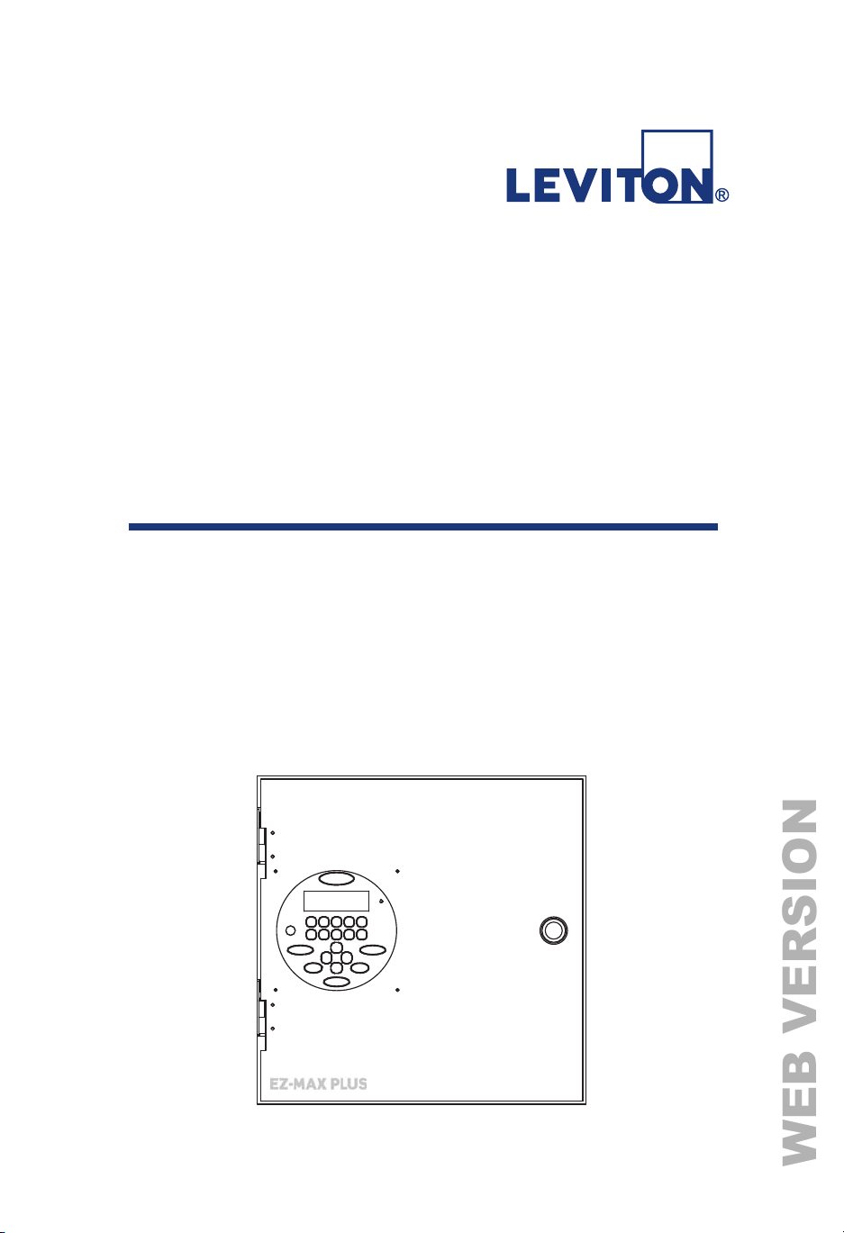
(=0$;3OXV
WEB VERSION
4XLFN6WDUW*XLGH
(=0$;3OXV5HOD\3DQHOV
6RIWZDUH5HYLVLRQDQGDERYH
Page 2
EZ-MAX Plus QuickStart.book Page 2 Thursday, January 22, 2009 1:55 PM
WEB VERSION
Overview
This EZ-MAX Plus Quick Start Guide assumes that you have
already installed your EZ-MAX Plus relay cabinet. This guide also
assumes you have read and familiarized yourself with the EZ-MAX
Plus Programmer Guide.
This guide covers an abbreviated version of the topics listed
below. See the EZ-MAX Plus Programmer Guide for complete
details and instructions on all topics.
• Time and Date—setting the time and date on your relay
cabinet.
• Set All Relays—globally configuring all relays in your
cabinet.
• Blink Warn Timer—configuring the blink warn timer
settings.
• Scheduler—creating a schedule of events.
• Configuring Inputs—configuring low voltage inputs
upancy sensors, photocells and switches) and digital
(occ
inputs.
OVERVIEW
QUICK START
EZ-MAX Plus Quick Start Guide
Page 2
Page 3

EZ-MAX Plus QuickStart.book Page 3 Thursday, January 22, 2009 1:55 PM
WEB VERSION
Page 3
EZ-MAX Plus Quick Start Guide
Page 4
EZ-MAX Plus QuickStart.book Page 4 Thursday, January 22, 2009 1:55 PM
WEB VERSION
Setting the Time and Date
SET TIME
You can change the following fields in the Time display:
• 12 or 24-hour clock
• Hours
• Minutes
• AM or PM
• Daylight Savings Time Mode:
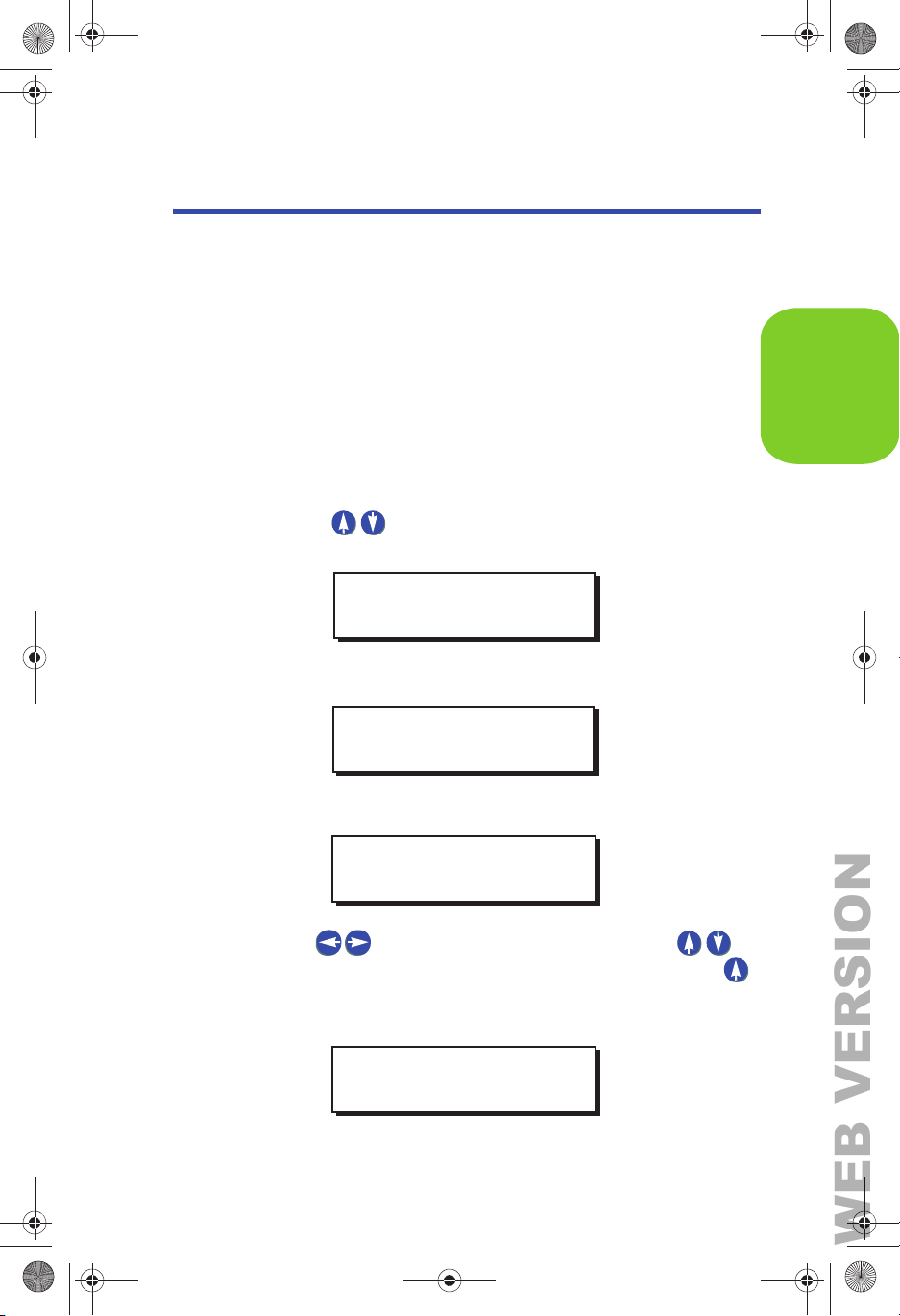
Step 1: Press the MENU button.
Step 2: Press until the display reads as shown below,
then press SELECT/SAVE.
MAIN MENU SELECT
SET TIME/DATE
TIME/DATE
Step 3: Press SELECT/SAVE.
MAIN MENU SELECT
SET TIME
The display will show the current setting for the time.
SET TIME 12 HOUR
4:46PM D: OFF
Step 4: Use to navigate through the fields. Use to
change the settings for each field. For example, use
to change the clock from a 12-hour clock to a 24-hour
clock:
SET TIME 24 HOUR
16:46S D: US
EZ-MAX Plus Quick Start Guide
Page 4
Page 5
EZ-MAX Plus QuickStart.book Page 5 Thursday, January 22, 2009 1:55 PM
WEB VERSION
Setting the Time and Date
Step 5: Press SELECT/SAVE when you have finished editing the
fields.
SET DATE
Step 1: Press the MENU button.
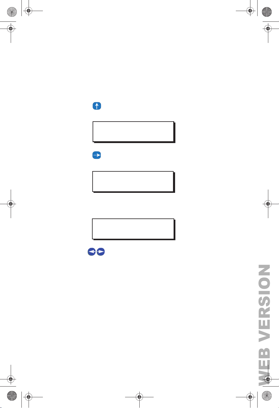
Step 2: Press until the display reads as below, then press
SELECT/SAVE.
MAIN MENU SELECT
SET TIME/DATE
Step 3: Press until the display reads SET DATE, then press
SELECT/SAVE
MAIN MENU SELECT
SET DATE
The display will show the current setting for the date, and the
active field will blink.
SET DATE MON
12/22/2008
Step 4: Use to navigate through the fields. Use the
numeric keypad to change the settings for each field.
Step 5: Press SELECT/SAVE when you have finished editing the
fields.
SET ASTRO CLOCK
Set Astro Clock by City
Follow the steps below to set the Astro Clock by using a quick city
code. See “Quick Codes for 101 Major Cities” on page 32 to see if
your city or a city near you is listed.
EZ-MAX Plus Quick Start Guide
Page 5
Page 6
EZ-MAX Plus QuickStart.book Page 6 Thursday, January 22, 2009 1:55 PM
WEB VERSION
Step 1: Press the MENU button.
Step 2: Press until the display reads as below, then press
SELECT/SAVE.
MAIN MENU SELECT
SET TIME/DATE
Step 3: Press until the display reads as below, then press
SELECT/SAVE.
MAIN MENU SELECT
SET ASTRO CLOCK
Step 4: The display should now read as below. Press SELECT/
SAVE.
TIME/DATE
SET ASTRO CLOCK
CITY
Step 5: Use the numeric keypad to enter the number that is
listed next to your city name (i.e. 55 for Las Vegas, NV),
and then press SELECT/SAVE.
LAS VEGAS
NV
EZ-MAX Plus Quick Start Guide
Page 6
Page 7
EZ-MAX Plus QuickStart.book Page 7 Thursday, January 22, 2009 1:55 PM
WEB VERSION
Setting the Time and Date
Set Astro Clock by Longitude/Latitude
Make sure you have the following information for your cit y before
you begin: current sunrise time, current sunset time, latitude.
This information can be found at www.srrb.noaa.gov/highlights/
sunrise/sunrise.html.
Step 1: Press the MENU button.
Step 2: Press until the display reads as shown below
MAIN MENU SELECT
SET TIME/DATE
Step 3: Press until the display reads as shown below, then
press
SELECT/SAVE.
MAIN MENU SELECT
SET ASTRO CLOCK
The display should now read:
SET ASTRO CLOCK
CITY
Step 4: Press until the display reads SUN/LAT, then press
SELECT/SAVE.
SET ASTRO CLOCK
SUN/LAT
Step 5: You will now be prompt ed to set the Sunrise (SR), Sunset
(SS) and Latitude (LA T) for your location. The active field
EZ-MAX Plus Quick Start Guide
Page 7
Page 8
EZ-MAX Plus QuickStart.book Page 8 Thursday, January 22, 2009 1:55 PM
WEB VERSION
will flash. Use the key to navigate between fields.
Use the numeric keypad to enter in the values.
SR=07:01A
SS=08:25P LAT=45
Step 6: Press the SELECT/SAVE button when you have finished
editing the fields.
TIME/DATE
EZ-MAX Plus Quick Start Guide
Page 8
Page 9

EZ-MAX Plus QuickStart.book Page 9 Thursday, January 22, 2009 1:55 PM
WEB VERSION
Setting the Time and Date
Page 9
EZ-MAX Plus Quick Start Guide
Page 10
EZ-MAX Plus QuickStart.book Page 10 Thursday, January 22, 2009 1:55 PM
WEB VERSION
Globally Configuring Relays
SET ALL RELAYS
Use the SET ALL RELAYS menu item to configure all of your
relays at once. Changing settings in this menu will change the
relay type for ALL relays in the cabinet, even if you have already
specified a different relay type to an individual relay.
See the EZ-Max Plus Programmer Guide for details on how to
configure individual relays.
Follow the steps below to configure the three global settings for
your relays.
Step 1: Press the MENU button.
Step 2: If you aren’t at the default screen, press or until
the display reads as shown below, then press
SELECT/SAVE.
MAIN MENU SELECT
SYSTEM SETTINGS
SET ALL RELAYS
Step 3: Press until the display reads SET ALL RELAYS , then
press SELECT/SAVE.
SYSTEM SETTINGS
SET ALL RELAYS
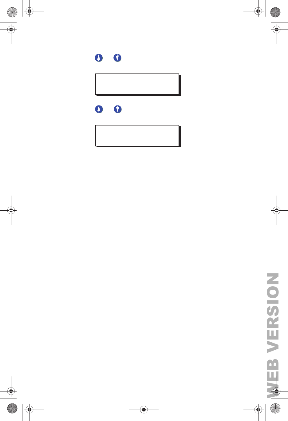
Step 4: Press or to toggle through the relay type choices.
Set your global relay type and press SELECT/SAVE.
ALL RELAY TYPE
LATCH (DEFAULT)
The system automatically saves the configuration change you
just made and displays the next menu item.
EZ-MAX Plus Quick Start Guide
Page 10
Page 11
EZ-MAX Plus QuickStart.book Page 11 Thursday, January 22, 2009 1:55 PM
WEB VERSION
Globally Configuring Relays
Step 5: Press or to toggle BLINK WARN to Y or N. Press
SELECT/SAVE.
ALL RELAYS
BLINK WARN? Y
Step 6: Press or to toggle EMERGENCY to OFF, ON or
NC. Press SELECT/SAVE.
ALL RELAYS
EMERGENCY? OFF
Your global relay configuration settings have now been saved.
Page 11
EZ-MAX Plus Quick Start Guide
Page 12
EZ-MAX Plus QuickStart.book Page 12 Thursday, January 22, 2009 1:55 PM
WEB VERSION
Configuring Blink Warn Parameters
Use the Global Timers menu to set your global Blink Warn
Parameters and the Timer setting for your Momentary Timed
switches.
Blink Warn Parameters
The blink warn feature is used to issue a warning just before the
relay cabinet turns off the lights. The warning is issued in the
form of a “blink” of the lights. Hence the term “Blink Warn.” The
Blink Warn feature has several configurable parameters to
determine the actions of your cabinet.
• OVRD TIME—sets the amount of time that the lights will
remain on when a user cancels a blink warn for their
particular zone. The setting defaults to 120 minutes.
• TIME OUT—sets the amount of time between when the blink
warn is issued and
defaults to 5 minutes.
• FLASH TIME—sets the length of the flash. The setting
defaults to 0.5 seconds.
the lights turn off (go black.) The setting
QUICK START
Momentary Timed interval
When using the “momentary timed” switch input type, a switch
input will trigger the lights on for the timer period specified in this
setting.
GLOBAL TIMERS
Follow the steps below to configure your global Blink Warn
settings, and the global setting for any switch set to “Momentary
Timed.”
EZ-MAX Plus Quick Start Guide
Page 12
GLOBAL TIMERS
Page 13
EZ-MAX Plus QuickStart.book Page 13 Thursday, January 22, 2009 1:55 PM
WEB VERSION
Configuring Blink Warn Parameters
Step 1: Press the MENU button.
Step 2: If you aren’t at the default screen, press or until
the display reads as shown below, then press
SELECT/SAVE.
MAIN MENU SELECT
SYSTEM SETTINGS
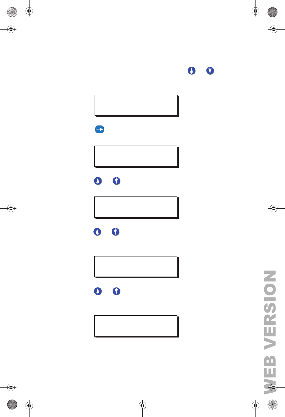
Step 3: Press until the display reads GLOBAL TIMERS, then
press SELECT/SAVE.
SYSTEM SETTINGS
GLOBAL TIMERS
Step 4: Press or to adjust the FLASH TIME. or use the
keypad to enter a specific time. Press SELECT/SAVE.
BLINK WARN
FLASH TIME: 0.3 S
Step 5: Press or to adjust the TIME OUT setting for Blink
Warn, or use the keypad to enter a specific time. Press
SELECT/SAVE.
BLINK WARN
TIME OUT: 5M
Step 6: Press or to adjust the Override Time (OVRD
TIME). or use the keypad to enter a specific time. Press
SELECT/SAVE.
BLINK WARN
OVRD TIME: 120M
EZ-MAX Plus Quick Start Guide
Page 13
Page 14
EZ-MAX Plus QuickStart.book Page 14 Thursday, January 22, 2009 1:55 PM
WEB VERSION
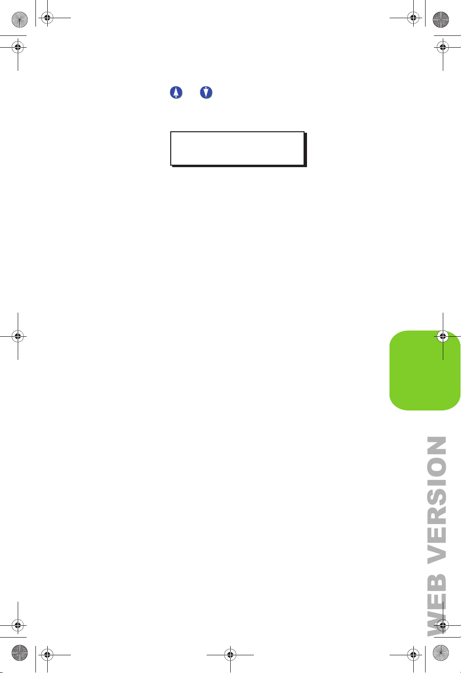
Step 7: Press or to adjust the TIMER setting for
Momentary Timed switches, or use the keypad to enter a
specific time. Press SELECT/SAVE.
TIME SWITCH
TIMER: 30M
All other programming functions will now use the above global
settings when setting a Blink Warn or a Momentary Timed switch.
QUICK START
GLOBAL TIMERS
EZ-MAX Plus Quick Start Guide
Page 14
Page 15

EZ-MAX Plus QuickStart.book Page 15 Thursday, January 22, 2009 1:55 PM
WEB VERSION
Configuring Blink Warn Parameters
Page 15
EZ-MAX Plus Quick Start Guide
Page 16
EZ-MAX Plus QuickStart.book Page 16 Thursday, January 22, 2009 1:55 PM
WEB VERSION
The Scheduler
SCHEDULER
Use the SCHEDULER menu to create, edit, or delete an event. An
“event” is defined as any action that occurs at a specific time.
NEW EVENT
You can control your lighting based on an event schedule that
you create. For example, you may want to create an event that
turns all lobby lights on at 7am Monday thru Friday, and another
event that turns all lobby lights off at 7pm Monday thru Friday.
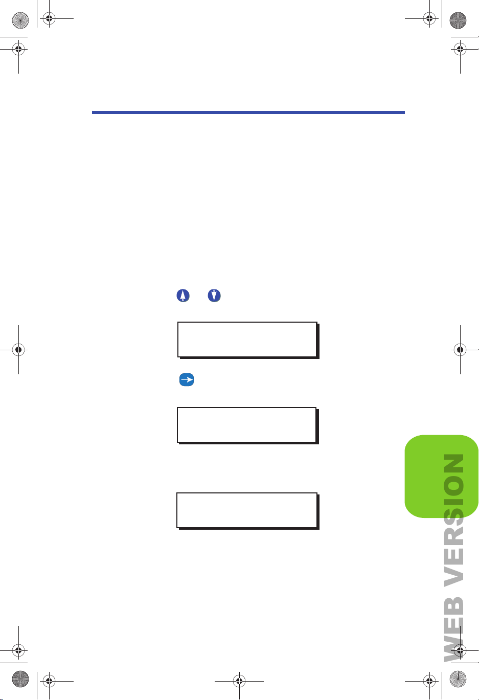
Step 1: Press the MENU button.
Step 2: Press or until the display reads as below, then
press SELECT/SAVE.
QUICK START
MAIN MENU SELECT
SCHEDULER
Step 3: Press until the display reads NEW EVENT, then
press SELECT/SAVE.
SCHEDULER
NEW EVENT
Step 4: Use the numeric keypad to enter an event number (001-
999) and press SELECT/SAVE.
ENTER EVENT #
E022:
The display will then prompt you to enter a “Time Type.” You can
set your event for a specific time of day, or according to sunrise
and sunset. The example below shows how to set an event time
based on the time of five minutes before sunrise.
EZ-MAX Plus Quick Start Guide
Page 16
SCHEDULER
Page 17
EZ-MAX Plus QuickStart.book Page 17 Thursday, January 22, 2009 1:55 PM
WEB VERSION
The Scheduler
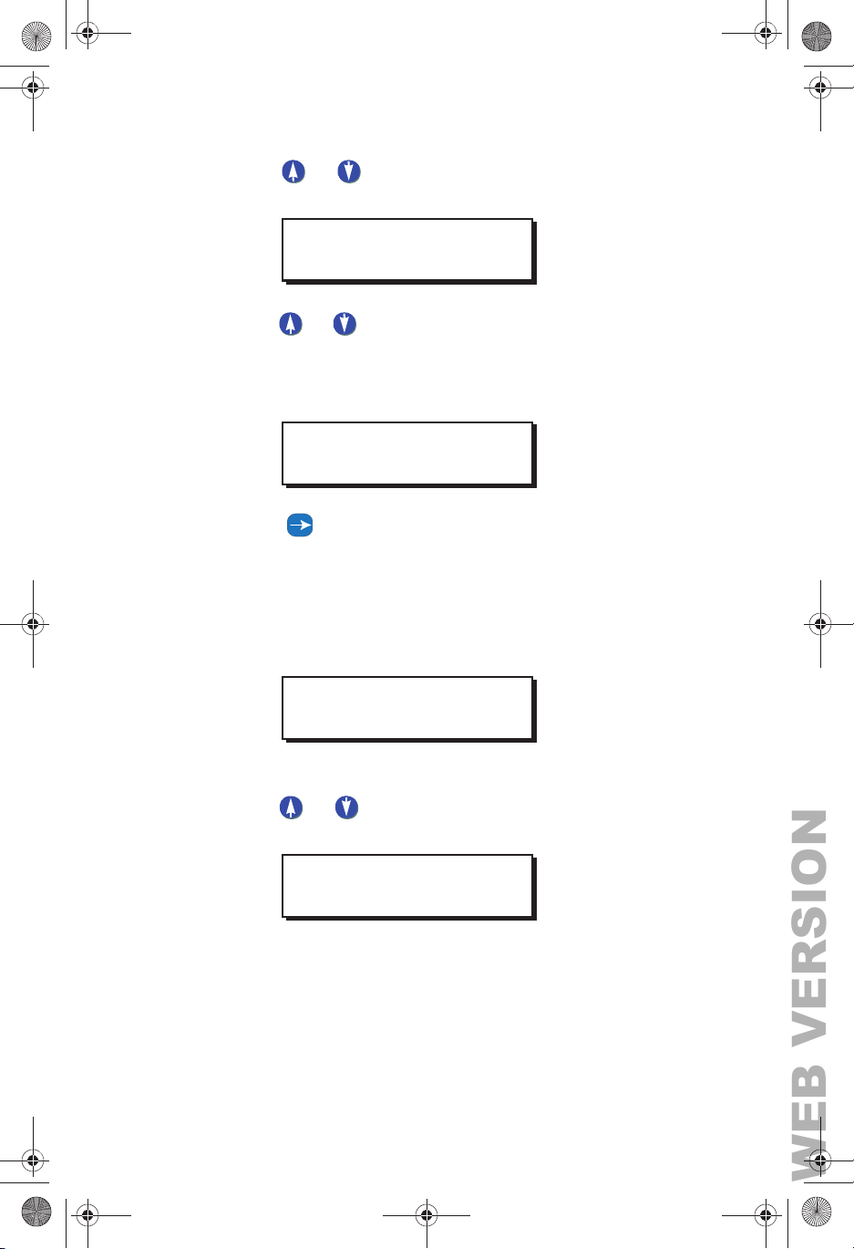
Step 5: Press or to toggle between TIME OF DAY and
SUNRISE/SUNSET, then press SELECT/SAVE.
ENTER TIME TYPE
SUNRISE/SUNSET
Step 6: Press or to toggle between SR+ and SS-. Use the
numeric keypad to enter the time of the event, and press
SELECT/SAVE when you have finished editing the
fields.
ENTER SR/SS TIME
SR-0:05
Step 7: Press to move through the days of the week. The
active field (day of the week) will flash. Press zero (0) to
disable a day of the week (displays as a slash), or press
an alpha key to enable a day of the week. Press
SELECT/SAVE when you have finished editing the
fields.
ENTER DAYS OF WK
MTWTF--
Step 8: Define whether or not this event will run on holidays.
Press or to toggle between the three Holiday
Mode choices. Press SELECT/SAVE.
HOLIDAY MODE
HOLIDAY ENABLED
Now define the Event Type and behavior.
EZ-MAX Plus Quick Start Guide
Page 17
Page 18
EZ-MAX Plus QuickStart.book Page 18 Thursday, January 22, 2009 1:55 PM
WEB VERSION
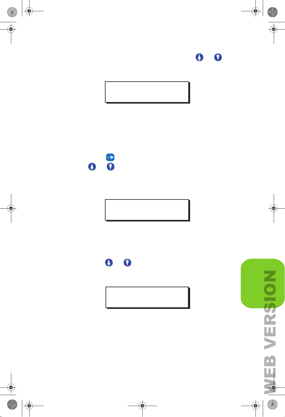
Step 9: The example below is for a relay. Press or to
toggle between the three choices until you get to RELAY,
and press SELECT/SAVE.
SELECT RLY MODE
RELAY ON
Assign the relays that will be associated with this event. If there
are 16 relays in your cabinet you will have to set each one to YES
or IGNORE, depending on whether or not you want the relay to
respond.
Step 10: Use the alphanumeric keys to input the relay number.
Press to navigate to the IGNORE/YES field. Press
or to toggle between YES and IGNORE and set
any relays you want to be a
Press SELECT/SAVE when you have finished setting all
relays.
ffected by this event to YES.
QUICK START
ASSIGN RELAYS
RELAY #01 YES
CHANGE EVNT TIME
Step 1: Press the MENU button.
Step 2: Press or until the display reads as below, then
press
SELECT/SAVE.
MAIN MENU SELECT
SCHEDULER
EZ-MAX Plus Quick Start Guide
Page 18
SCHEDULER
Page 19
EZ-MAX Plus QuickStart.book Page 19 Thursday, January 22, 2009 1:55 PM
WEB VERSION
The Scheduler
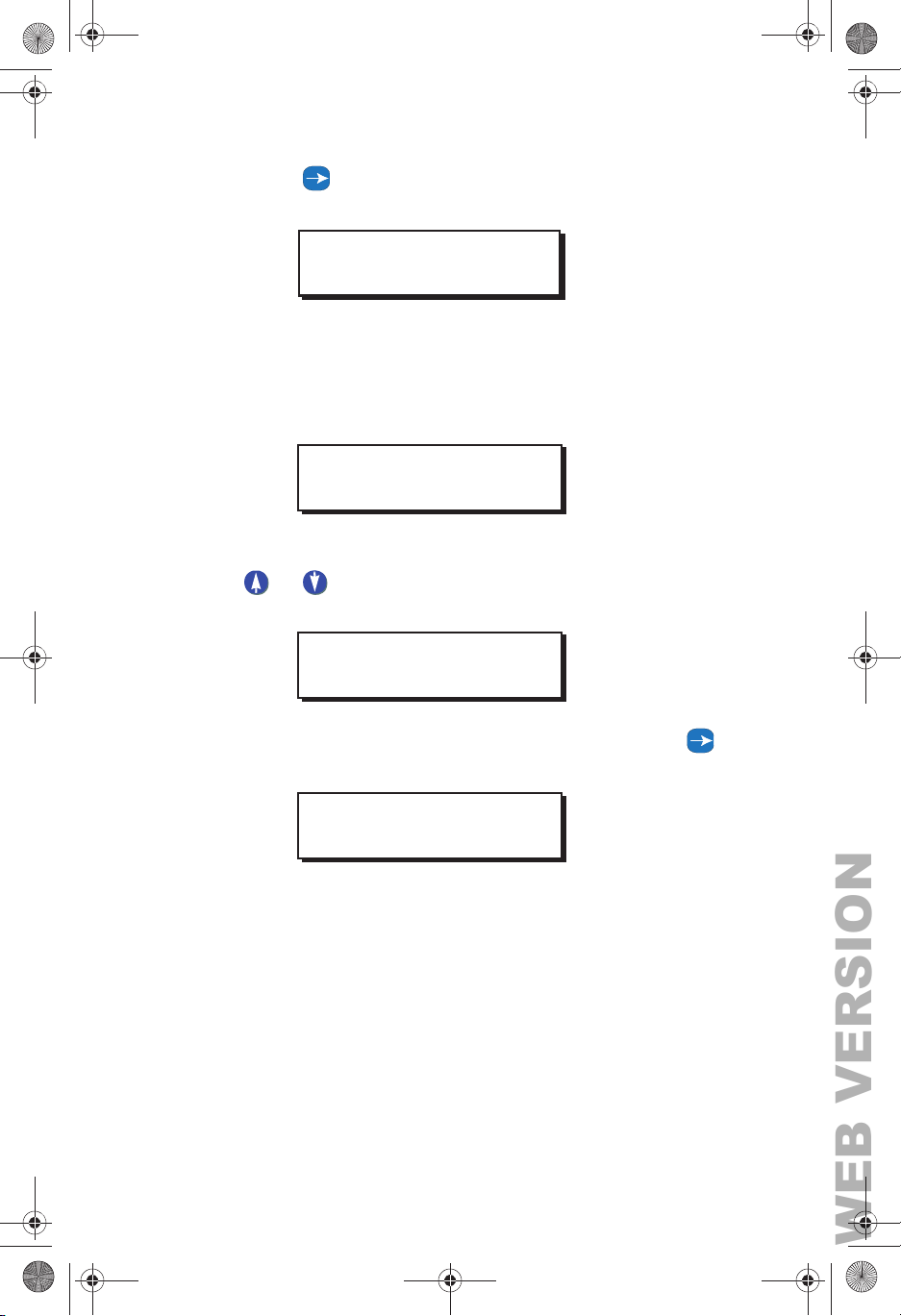
Step 3: Press until the display reads CHANGE EVNT TIME,
then press SELECT/SAVE.
SCHEDULER
CHANGE EVNT TIME
Step 4: Use the numeric keypad to enter the event number you
want to modify. Once you actually enter the event
number the event time will display. Press SELECT/
SAVE.
SELECT EVENT #
E022: 7:00AM
Step 5: You will then be prompted to choose a Time Type. Press
or to toggle between the two time types (TIME
OF DAY and SUNRISE/SUNSET). Press SELECT/SAVE.
EDIT TIME TYPE
TIME OF DAY
Step 6: Use the numeric keypad to enter a new time. Press
to navigate the fields. Press SELECT/SAVE.
EDIT TIME
7:00AM
Step 7: Press SELECT/SAVE when you have finished editing the
fields.
DELETE EVENT
You might find out down the line that you don’t need all of the
events that you originally programmed into your EZ-MAX Plus
system. It’s a very simple process to delete an event.
EZ-MAX Plus Quick Start Guide
Page 19
Page 20

EZ-MAX Plus QuickStart.book Page 20 Thursday, January 22, 2009 1:55 PM
WEB VERSION
Step 1: Press the MENU button.
Step 2: Press or until the display reads as below, then
press SELECT/SAVE.
MAIN MENU SELECT
SCHEDULER
Step 3: Press until the display reads DELETE EVENT, then
press SELECT/SAVE.
SCHEDULER
DELETE EVENT
Step 4: Use the numeric keypad to enter the event number you
want to delete. Once you actually enter the event
number the event time will display. Press SELECT/
SAVE.
QUICK START
SELECT EVENT
E022: 7:00AM
Step 5: Press or to toggle to “Y,” and press SELECT/
SAVE.
DELETE EVENT: Y
E022: 7:00AM
Your event has been deleted.
EZ-MAX Plus Quick Start Guide
Page 20
SCHEDULER
Page 21
EZ-MAX Plus QuickStart.book Page 21 Thursday, January 22, 2009 1:55 PM
WEB VERSION
The Scheduler
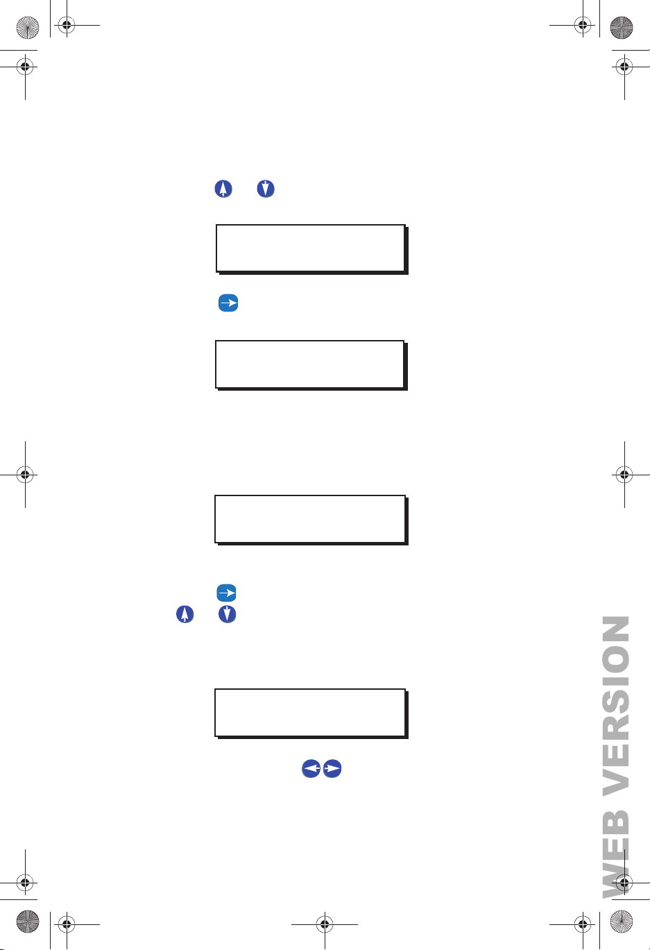
EDIT EVENT
Step 1: Press the MENU button
Step 2: Press or until the display reads as below, then
press SELECT/SAVE.
MAIN MENU SELECT
SCHEDULER
Step 3: Press until the display reads EDIT EVENT, then
press SELECT/SAVE.
SCHEDULER
EDIT EVENT
Step 4: Use the numeric keypad to enter the event number you
want to modify. Once you actually enter the event
number the event time will display. Press
SELECT/SAVE.
SELECT EVENT #
E022: 7:00AM
Step 5: Use the alphanumeric keys to input the relay number.
Press to navigate to the IGNORE/YES field. Press
or to toggle between YES and IGNORE and set
any relays you want to be affected by this event to YES.
Press SELECT/SAVE when you have finished setting all
relays.
ASSIGN RELAYS
RELAY #01 YES
Step 6: Continue to use the to move between the relay
field and the behavior field, and cycle through all relays
until you have set all of them to YES or IGNORE. Press
EZ-MAX Plus Quick Start Guide
Page 21
Page 22
EZ-MAX Plus QuickStart.book Page 22 Thursday, January 22, 2009 1:55 PM
WEB VERSION
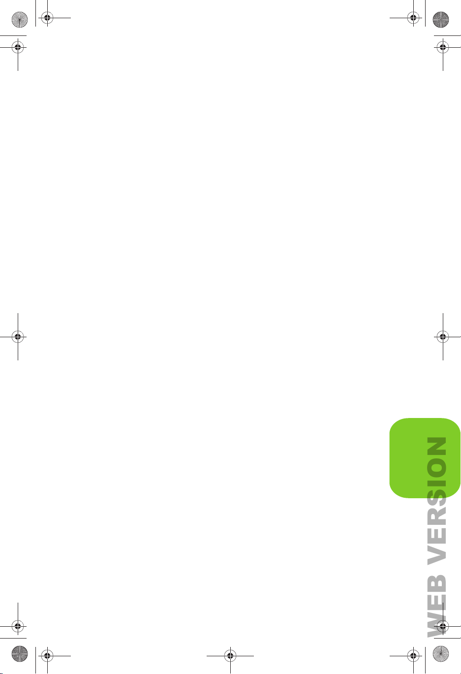
Select/Save when you have finished assigning all
relays.
QUICK START
SCHEDULER
EZ-MAX Plus Quick Start Guide
Page 22
Page 23

EZ-MAX Plus QuickStart.book Page 23 Thursday, January 22, 2009 1:55 PM
WEB VERSION
The Scheduler
Page 23
EZ-MAX Plus Quick Start Guide
Page 24
EZ-MAX Plus QuickStart.book Page 24 Thursday, January 22, 2009 1:55 PM
WEB VERSION
Configuring Inputs
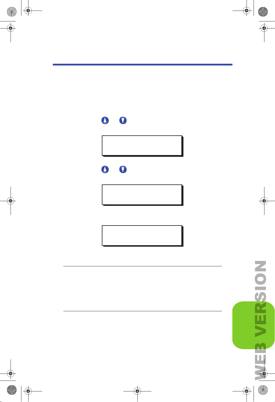
CONFIG INPUTS
LV INPUT—Switch
Step 1: Press the MENU button.
Step 2: Press or until the display reads as below, then
press SELECT/SAVE.
MAIN MENU SELECT
CONFIG INPUTS
Step 3: Press or to navigate to LV INPUT, and press
Select/Save.
QUICK START
INPUT TYPE
LV INPUT
Step 4: Set the low voltage input for the switch.
SELECT INPUT
1: SWITCH
NOTE: If you are configuring a multi-button switch, the
number you enter in the SWITCH field corresponds to a
specific button on the switch. The top button on the switch
would be #1 in the SWITCH field. The second button down
would be #2 in the SWITCH field, and so on.
EZ-MAX Plus Quick Start Guide
Page 24
CONFIG INPUTS
Page 25
EZ-MAX Plus QuickStart.book Page 25 Thursday, January 22, 2009 1:55 PM
WEB VERSION
Configuring Inputs
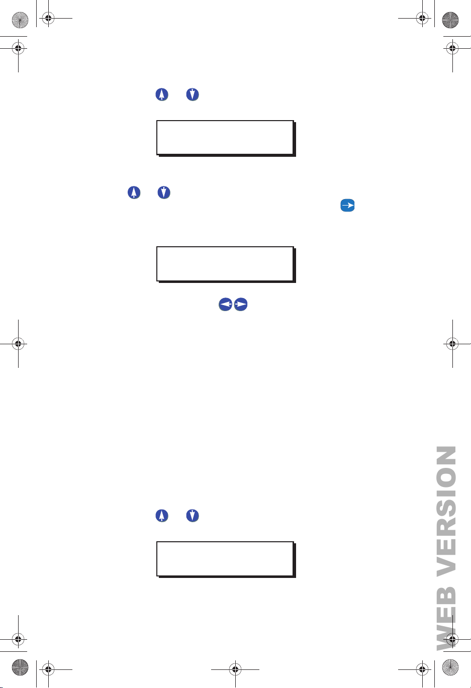
Step 5: Press or to choose a behavior for this particular
button. Press Select/Save.
LV SWITCH TYPE
MOMENTARY
Step 6: Assign a relay (or multiple relays) to the switch. Press
or to cycle through the relay numbers, or use the
numeric keypad to enter a relay number. Press to
navigate to the next field and toggle IGNORE to YES if
you want to assign the relay.
ASSIGN RELAYS
RELAY# 3: YES
Step 7: Continue to use the to move between the relay
field and the behavior field, and cycle through all relays
until you have set all of them to YES or IGNORE. Press
Select/Save when you have finished assigning all
relays.
If you are configuring a multi-button switch, continue to repeat
the above steps until you’ve configured all buttons on the switch.
LV INPUT—OCC
Configuring Occupancy Sensors
These instructions assume that your Occupancy Sensor is already
connected to one of the low voltage inputs.
Step 1: Press the MENU button.
Step 2: Press or until the display reads as below, then
press SELECT/SAVE.
MAIN MENU SELECT
CONFIG INPUTS
EZ-MAX Plus Quick Start Guide
Page 25
Page 26
EZ-MAX Plus QuickStart.book Page 26 Thursday, January 22, 2009 1:55 PM
WEB VERSION
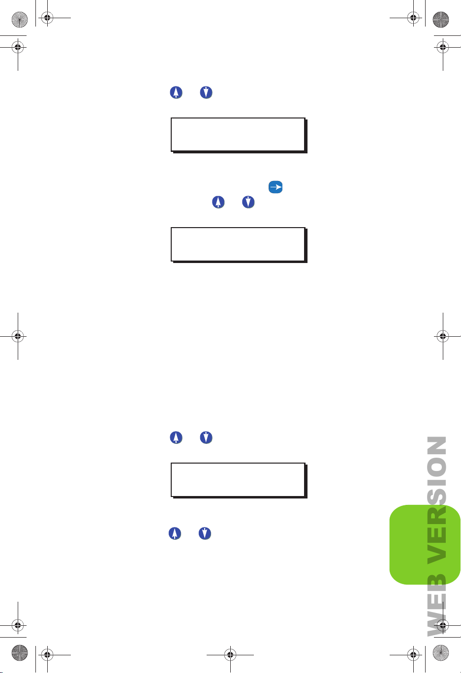
Step 3: Press or to navigate to LV INPUT, and press
Select/Save.
INPUT TYPE
LV INPUT
Step 4: Use the numeric keypad to enter the input number for
the occupancy sensor. Press to navigate to the next
field, and press or to change the field to OCC.
Press Select/Save.
SELECT INPUT
2: OCC
The next step is to choose the behavior of your occupancy
sensor.
• Manual (Manual On-Auto Off)— The occupancy sensor will
turn off the assigned relays when the occupancy sensor
indicates an unoccupied state. When the room becomes
occupied, the relays will not be automatically turned on,
instead,
a wall switch or other input.
• Auto (Always On/Auto Off)—In this mode, the Oc cupancy
Sensor will turn the assigned relays both on and off based on
either an occupied or unoccupied stated indicated by the
occupancy sensor.
the user will have to manually turn on the lights from
QUICK START
Step 5: Press or to select the behavior INTERIOR or
EXTERIOR, and press Select/Save.
Step 6: Assign the relay (or relays) to this occupancy sensor.
Press or to cycle through the relay numbers, or
use the numeric keypad to enter a relay number. Press
OCC SENSOR MODE
INTERIOR
CONFIG INPUTS
EZ-MAX Plus Quick Start Guide
Page 26
Page 27
EZ-MAX Plus QuickStart.book Page 27 Thursday, January 22, 2009 1:55 PM
WEB VERSION
Configuring Inputs
to navigate to the next field and toggle IGNORE to
YES if you want to assign the relay.
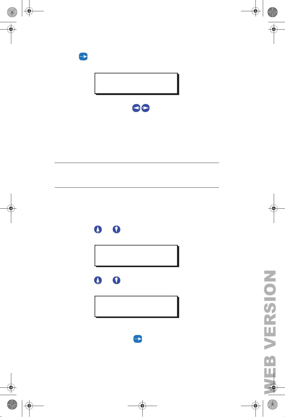
ASSIGN RELAYS
RELAY# 3: YES
Step 7: Continue to use the to move between the RELAY
field and the behavior field, and cycle through all relays
until you have set all of them to YES or IGNORE. Press
Select/Save when you have finished assigning all
relays.
NOTE: Occupancy sensor Delay times and Retrigger times
must be set on the occupancy sensor itself.
LV INPUT—Photocell
Step 1: Press the MENU button.
Step 2: Press or until the display reads as below, then
press SELECT/SAVE.
MAIN MENU SELECT
CONFIG INPUTS
Step 3: Press or to navigate to LV INPUT, and press
Select/Save.
INPUT TYPE
LV INPUT
Step 4: Use the numeric keypad to enter the input number for
the photocell. Press to navigate to the next field,
EZ-MAX Plus Quick Start Guide
Page 27
Page 28
EZ-MAX Plus QuickStart.book Page 28 Thursday, January 22, 2009 1:55 PM
WEB VERSION
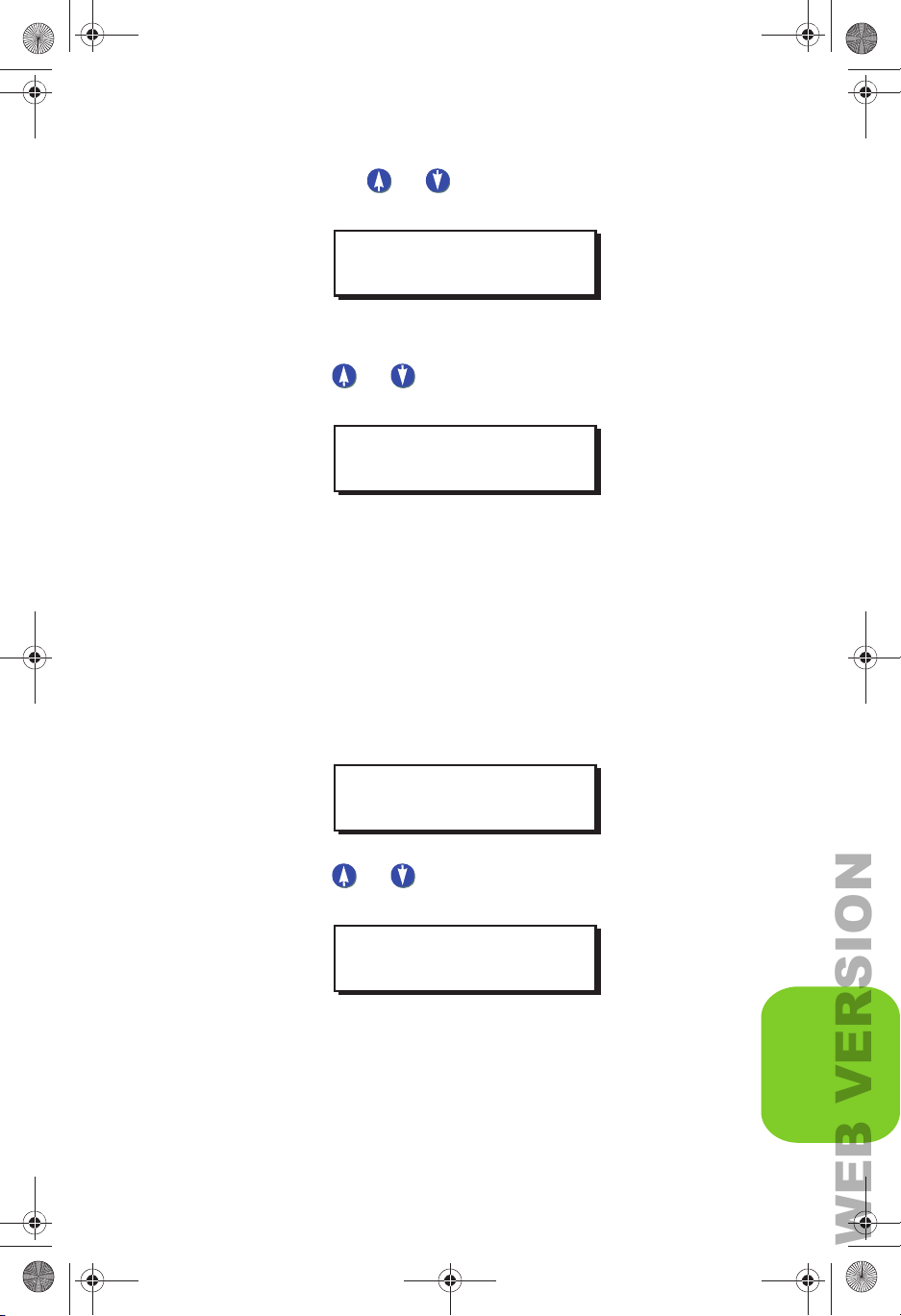
and press or to change the field to PHOTOCELL.
Press Select/Save.
SELECT INPUT
2: PHOTOCELL
The next step is to choose the behavior of your photocell.
Step 5: Press or to select the behavior INTERIOR or
EXTERIOR, and press Select/Save.
PHOTOCELL
INTERIOR
The next step is to define a Delay Time.
• Delay Time—used to prevent rapid changes to lighting
based on changing conditions in the environment. For
example, clouds passing the sun which temporarily darkens
the space. It is expressed in minutes and represents the
length of contiguous time between trigger points in order for
the relays to be turned on or off.
QUICK START
Step 6: Use the numeric keypad to enter a delay time, and press
Select/Save.
PHOTOCELL
DELAY TIME: 5 M
Step 7: Press or to select the type of photocell (either
0-10 Volt or Switched), and press Select/Save.
PHOTOCELL TYPE
0-10 VOLT
If you choose 0-10 VOLT you will be prompted to provide a
minimum activation (ON) voltage and a minimum OFF voltage
setting.
EZ-MAX Plus Quick Start Guide
Page 28
CONFIG INPUTS
Page 29
EZ-MAX Plus QuickStart.book Page 29 Thursday, January 22, 2009 1:55 PM
WEB VERSION
Configuring Inputs
• On Voltage must be a voltage between 1-10 VDC, AND must
be less than the OFF voltage.
• OFF V oltage must be a voltage between 1-10 VDC, AND must
be greater than the ON voltage.
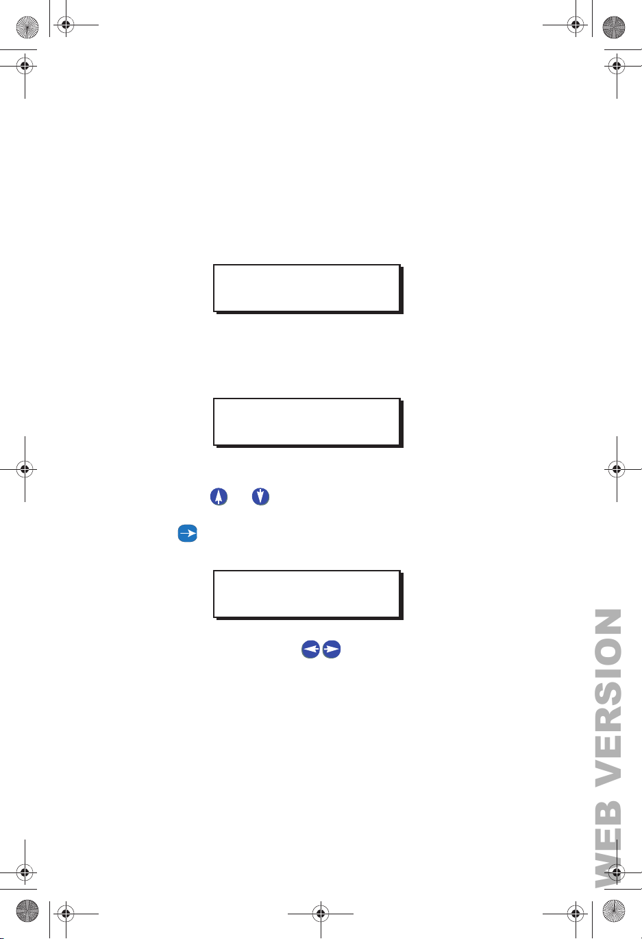
Step 8: Enter the level, in volts, for which you desire these relays
to be activated when the light levels are FALLING (ON).
Press Select/Save.
PHOTOCELL
ON VOLTS: 4.0
Step 9: Enter the level, in volts, for which you desire these relays
to be deactivated when the light levels are RISING (OFF).
Press Select/Save
PHOTOCELL
OFF VOLTS: 6.0
Step 10: Assign the relay (or relays) to this occupancy sensor.
Press or to cycle through the relay numbers, or
use the numeric keypad to enter a relay number. Press
to navigate to the next field and toggle IGNORE to
YES if you want to assign the relay.
ASSIGN RELAYS
RELAY# 3: YES
Step 11: Continue to use the to move between the RELAY
field and the behavior field, and cycle through all relays
until you have set all of them to YES or IGNORE. Press
Select/Save when you have finished assigning all
relays.
DIGITAL INPUT—Switch
The steps below show you how to manually input a digital switch
into the system. If you install your digital switches first, and then
EZ-MAX Plus Quick Start Guide
Page 29
Page 30
EZ-MAX Plus QuickStart.book Page 30 Thursday, January 22, 2009 1:55 PM
WEB VERSION
use the auto-assign feature, your digital switch addresses will be
displayed automatically when you get to the SELECT SWITCH
step.
Step 1: Press the MENU button.
Step 2: Press or until the display reads as below, then
press SELECT/SAVE.
MAIN MENU SELECT
CONFIG INPUTS
Step 3: Press or to navigate to DIGITAL INPUT, and
press Select/Save.
INPUT TYPE
DIGITAL INPUT
QUICK START
Step 4: Use the numeric keypad to enter the address for the
digital switch. Press Select/Save.
SELECT SWITCH
ADDRESS: 74
Program the behavior for all buttons on your switch. If you have
a 4-button switch you will go through the steps below four times.
Step 5: Use the numeric keypad to enter the button number you
want to program. Press Select/Save.
ADDRESS: 74
BUTTON: 4
Step 6: Press or to choose a behavior for this particular
button. Press Select/Save.
ADDR: 74 BTN: 4
MOMENTARY TIMED
EZ-MAX Plus Quick Start Guide
Page 30
CONFIG INPUTS
Page 31
EZ-MAX Plus QuickStart.book Page 31 Thursday, January 22, 2009 1:55 PM
WEB VERSION
Configuring Inputs
Step 7: Assign the switch to a particular relay. Use the numeric
keypad to enter a relay number. Press to navigate
to the next field and toggle IGNORE to YES if you want
to assign the relay . Cycle thr ough all relays until you have
set all of them to YES or IGNORE. Press Select/Save.
ASSIGN RELAYS
RELAY# 3: YES
Step 8: Continue to use the to move between the relay
field and the behavior field, and cycle through all relays
until you have set all of them to YES or IGNORE. Press
Select/Save when you have finished assigning all
relays.
Page 31
EZ-MAX Plus Quick Start Guide
Page 32

EZ-MAX Plus QuickStart.book Page 32 Thursday, January 22, 2009 1:55 PM
WEB VERSION
Quick Codes for 101 Major Cities
1 Albany, NY
2 Albuquerque, NM
3 Allentown, PA
4 Anchorage, AK
5 Atlanta, GA
6 Atlantic City, NJ
7 Augusta, GA
8 Austin, TX
9 Bakersfield, CA
10 Baltimore, MD
11 Bangor, ME
12 Baton Rouge, LA
13 Beijing, China
14 Biloxi, MS
15 Birmingham, AL
16 Bismarck, ND
17 Boise, ID
26 Chattanooga. TN
27 Cheyenne, WY
28 Chicago, IL
29 Cincinnati, OH
30 Cleveland, OH
31 Columbus, OH
32 Dallas, TX
33 Daytona Beach, FL
34 Denver, CO
35 Des Moines, IA
36 Detroit, MI
37 El Paso, TX
38 Edmonton, AB
39 Erie, PA
40 Evansville, IN
41 Fairbanks, AK
42 Fort Wayne, IN
QUICK START
18 Boston, MA
19 Bridgeport, CT
20 Buffalo, NY
21 Burlington, VT
22 Calgary, AB
23 Cambridge, MA
24 Charleston, SC
25 Charlotte, NC
43 Fort Worth, TX
44 Fresno, CA
45 Grand Rapids, MI
46 Hartford, CT
47 Hong Kong, China
48 Honolulu, HI
49 Houston, TX
50 Indianapolis, IN
EZ-MAX Plus Quick Start Guide
Page 32
Page 33

EZ-MAX Plus QuickStart.book Page 33 Thursday, January 22, 2009 1:55 PM
WEB VERSION
Quick Codes for 101 Major Cities
51 Iowa City, IA
52 Jackson, MS
53 Jacksonville, FL
54 Kansas City, MO
55 Las Vegas, NV
56 Little Rock, AR
57 Los Angeles, CA
58 Louisville, KY
59 Memphis, TN
60 Mexico City, MX
61 Miami, FL
62 Milwaukee, WI
63 Minneapolis, MN
64 Mobile, AL
65 Montreal QC
66 Nashville, TN
67 New Orleans, LA
79 Providence, RI
80 Reno, NV
81 Rochester, NY
82 Sacramento, CA
83 Salt Lake City, UT
84 San Diego, CA
85 San Francisco, CA
86 Scranton, PA
87 Seattle, WA
88 Springfield, MA
89 St. Louis, MO
90 Sudbury, ON
91 Syracuse, NY
92 Tampa, FL
93 Toronto, ON
94 Trenton, NJ
95 Tucson, AZ
68 New York City, NY
69 Norfolk, VA
70 Oklahoma City, OK
71 Omaha, NE
72 Orlando, FL
73 Ottawa, ON
74 Philadelphia, PA
75 Phoenix, AZ
76 Pittsburgh, PA
77 Portland, ME
78 Portland, OR
Page 33
96 Tulsa, OK
97 Vancouver BC
98 Virginia Beach, VA
99 Was hi ng ton, D.C.
100Wichita, KS
101Winnipeg, MN
EZ-MAX Plus Quick Start Guide
Page 34

EZ-MAX Plus QuickStart.book Page 1 Thursday, January 22, 2009 1:55 PM
WEB VERSION
Warranty Information
Limited Warranty
Leviton Manufacturing Co Inc. warrants the products represented in
this manual to be free of material and workmanship defects for a
period of two years after system acceptance or 26 months after
shipment from Leviton, whichever comes first. The EZ-MAX Plus relay
cards are covered for a period of ten (10) years. Lighting fixtures
manufactured by Leviton are covered for a period of one year.
This Warranty is limited to repair or replacement of defective
equipment returned Freight Pre-Paid to Leviton Manufacturing at
20497 SW Teton Ave., Tualatin, Oregon 97062, USA. User shall call
1-800-959-6004 and request a return authorization number to mark
on the outside of the returning carton, to assure that the returned
material will be properly received at Leviton.
All equipment shipped back to Leviton must be carefully and properly
packed to avoid shipping damage. Replacements or repaired
equipment will be returned to sender freight prepaid, F. O.B. factory.
Leviton is not responsible for removing or replacing equipment on the
job site, and will not honor charges for such work. Leviton will not be
responsible for any loss of use time or subsequent damages should
any of the equipment fail during the warranty period, but agrees only
to repair or replace defective equipment returned to its plant in
Tualatin, Oregon.
This Warranty is void on any product that has been improperly
installed, overloaded, short circuited, abused, or altered in any
manner. Neither the seller nor Leviton shall be liable for any injury,
loss or damage, direct or consequential arising out of the use of or
inability to use the equipment. This Warranty does not cover lamps,
ballasts, and other equipment which is supplied or warranted directly
to the user by their manufacturer. Leviton makes no warranty as to
the Fitness for Purpose or other implied Warranties.
Page 35
NOTES
WEB VERSION
Page 36
NOTES
WEB VERSION
Page 37
NOTES
WEB VERSION
Page 38
NOTES
WEB VERSION
Page 39
NOTES
WEB VERSION
Page 40
NOTES
WEB VERSION
Page 41
NOTES
WEB VERSION
Page 42
NOTES
WEB VERSION
Page 43
NOTES
WEB VERSION
Page 44
NOTES
WEB VERSION
Page 45

NOTES
WEB VERSION
Page 46
NOTES
WEB VERSION
Page 47
NOTES
WEB VERSION
Page 48
NOTES
WEB VERSION
Page 49
NOTES
WEB VERSION
Page 50
Leviton Lighting Management Systems Division Headquarters
WEB VERSION
20497 SW Teton Avenue, Tualatin, OR 97062
Customer Service THOHSKRQHFAX: 1-503-404-5600
Tech Line: 1-800-959-6004
Leviton Manufacturing Co., Inc.
201 North Service Road, Melivlle, N.Y. 11747
THOHSKRQHFAX: 1-800-832-9538
Visit Leviton’s Web site at http://www.leviton.com
© 2010 Leviton Manufacturing Co., Inc. All Rights Reserved
PK-93783-10-00-0B
 Loading...