

Page 1

Advanced
Programming &
Systems Design Guide
Z-MAX
Covering Z-Max Master, Z-Max Remote, & EZ-Max Relay Panels
Software Revision 1.40 and above.
TM
RELAY PRODUCTS
.
Page 2

Page 3

Table of Contents
Complete Table of Contents ........................................................................................iii
Overview ................................................................................................................... 1
Warnings - READ ME FIRST ........................................................................................ 4
Part I - Front Panel Operation & Visual Status
Visual Status and Operational Feedback......................................................................11
Touch-Tone Telephone Interface................................................................................17
Part II - Simple Mode Programming
Configuration the Simple Way ....................................................................................21
Part III - Advanced Programming Guide
Global Defaults..........................................................................................................39
Relays ......................................................................................................................45
Luma-Net .................................................................................................................49
DMX512 ...................................................................................................................51
Phone/Modem Setup .................................................................................................53
Operation .................................................................................................................55
Ethernet Module........................................................................................................63
Priorities ...................................................................................................................65
Passwords ................................................................................................................67
Switch/Discrete Inputs...............................................................................................69
Action Editor .............................................................................................................83
Scheduler .................................................................................................................91
Event Editor..............................................................................................................98
"CLIF" - Command Line Interface .............................................................................103
Updating Firmware..................................................................................................107
Part IV - System Design Guide
Special Considerations for Networks .........................................................................125
Master/Slave Network Topology ...............................................................................127
Remote Cabinet Configuration..................................................................................135
Low Voltage Control Wiring......................................................................................155
Connecting Low Voltage Switches.............................................................................161
Power-Up & Installation Verification Checklist............................................................173
Warranty Information ..............................................................................................185
Page i
Page 4

,
Page ii
Page 5

Complete Table of Contents
Complete Table of Contents
Overview
Introduction.......................................................................................................... 1
Product Specifications & Capabilities ....................................................................... 2
Product Specifications & Capabilities Chart ......................................................... 2
Warnings - READ ME FIRST
Setting the Date, Time, & Astronomical Time Clock.................................................. 7
Set the Date & Time.............................................................................................. 7
Set the Astronomical Time Clock........................................................................ 8
Visual Status and Operational Feedback
What are all these blinking lights? ....................................................................11
System Status LED’s .............................................................................................11
Relay Status LED’s.....................................................................................................13
Determine the Firmware/Software Build.................................................................15
Touch-Tone Telephone Interface
Command Mode ..............................................................................................17
User Mode ......................................................................................................17
Administrator Mode .........................................................................................18
Configuration the Simple Way
Panel Configuration in Simple Mode.......................................................................21
Simple Mode Menu Structure.................................................................................22
Changing Configuration Modes ..............................................................................22
Configure Inputs ..................................................................................................23
Low Voltage Switch Inputs...............................................................................23
Photocell Configuration ....................................................................................25
Occupancy Sensor Configuration ......................................................................28
Quick Schedule ...............................................................................................29
Factory Defaults...................................................................................................33
Saving & Restoring Configuration ..........................................................................33
Advanced Mode Menu Structure ............................................................................37
Global Defaults
Changing the # of Local Relays ........................................................................39
Remote Relays ................................................................................................39
Enable Master/Remote communication....................................................39
Sequence Delay Time ............................................................................40
Sweep Interval......................................................................................40
Blink Warn Parameters...........................................................................41
Momentary Timed interval......................................................................41
Page iii
Page 6

,
Relays
Navigating the Relay Menu ..............................................................................45
To set the Relay Type......................................................................................45
To assign relays to groups ...............................................................................46
Turning feedback On or Off: ............................................................................47
To alter if a relay will respond to a blink warn message......................................47
To change the Luma-Net address for a specific relay .........................................47
To change the DMX Address for a specific relay.................................................47
Altering the way a Relay Responds to the Emergency Signal: .............................48
Luma-Net
Cabinet Luma-Net Address...............................................................................49
Cabinet start address/Automatic Luma-Net channel assignment..........................50
Operation Mode ..............................................................................................50
DMX512
DMX Start Address ..........................................................................................51
Phone/Modem Setup
Operation Mode ..............................................................................................53
Operation
LCD Display .........................................................................................................55
Navigation Buttons ..........................................................................................56
Turning Relays On/Off from the front panel and front panel overrides......................57
To Turn a Relay On or Off...........................................................................57
To Override a Relay On or Off ..........................................................................58
To Override a Relay On or Off for a specified time .............................................58
Internal Relay Cabinet Controls .............................................................................59
Master Override ...................................................................................................59
Individual Relay Overrides ....................................................................................60
To temporarily change a relays state using its override Switch:...........................62
To lock out a relay using its override switch: .....................................................62
To unlock a relay using its override switch: .......................................................62
Ethernet Module
Operation Mode ..............................................................................................63
Priorities
Passwords
Editing Passwords ...........................................................................................68
Auto-Repeat..........................................................................................57
Switch/Discrete Inputs
Switch Numbering ...........................................................................................69
Page iv
Page 7

Define Switch Types .............................................................................................70
Assign Actions to Inputs .......................................................................................71
Relay assignment to inputs ..............................................................................72
Switch Inputs..................................................................................................73
Occupancy Inputs............................................................................................76
Contact Closures .............................................................................................77
Photocell and Photocell Levels ..........................................................................78
Action Editor
Editing and Deleting Actions.............................................................................88
Edit an Item: ..................................................................................................89
Delete an Item:...............................................................................................89
Digital Switches..........................................................................................74
Blink Warn .................................................................................................76
Daylight Harvesting ...............................................................................79
Photocells .............................................................................................80
Adding an Action ........................................................................................83
Action Item Types: ................................................................................84
Edit an Item:.........................................................................................87
Delete an Item:.....................................................................................88
To exit the Item Editor...........................................................................88
Edit an Action: ...........................................................................................88
Delete an Action.........................................................................................89
Scheduler
Holiday Editor .................................................................................................91
Add a New Holiday .....................................................................................91
Standard Holiday List.............................................................................91
Custom Holiday List ...............................................................................93
Edit a Holiday.............................................................................................95
Delete a Holiday.........................................................................................96
To exit the Holiday Editor.......................................................................97
Activate or Deactivate the Scheduler:................................................................97
Event Editor
Add a New Event........................................................................................98
Edit an Event .............................................................................................99
Delete an Event........................................................................................101
"CLIF" - Command Line Interface
Help ..................................................................................................................103
CLIF Commands.................................................................................................104
Updating Firmware
Power Considerations for Control Systems............................................................117
Terminology..................................................................................................117
Page v
Page 8

,
Power Requirements & Maximum Run Length .................................................118
Power Control Devices - Available Supply Current .......................................118
Power Wire - Run Length...............................................................................121
Wiring with an External Power Supply............................................................. 123
Special Considerations for Networks
Luma-Net Network (page 145) .......................................................................125
DMX Network (page 141)...............................................................................125
Modem Network (page 163)...........................................................................125
Ethernet Network Overview (page 167) .......................................................... 125
Master/Remote Network (page 127) ...............................................................125
Master/Slave Network Topology
Network Topology ...................................................................................................128
Physical Requirements.............................................................................................129
RJ-45 Pinout .................................................................................................129
Termination ..................................................................................................130
How to Terminate Relay Cabinets................................................................... 131
Network Layout Planning .........................................................................................132
Relay Numbering Chart..................................................................................133
Relay Numbering Chart............................................................................................134
Remote Cabinet Configuration
Out of the Box Configuration..........................................................................135
Remote/Slave Cabinet Configuration....................................................................135
Comments & Examples on Relay Numbering ...................................................135
Configuration of Remote Relay Cabinets with Dipswitches ................................135
Table of MRN Codes & Starting Relay Number.................................................136
Configuration of Remote Relay Cabinets without Dipswitches or via USB ........... 137
Configuration of Master Control Panel..................................................................138
Enable Master/Slave Communication ..............................................................138
Enabling Master/Slave Communication............................................................138
Setting the Total number of Remote Relays.....................................................138
Communication Verification.................................................................................139
Conclusion.........................................................................................................140
DMX 512 ................................................................................................................141
Topology Requirements .................................................................................141
Termination Requirements ........................................................................141
Physical Specifications ................................................................................... 143
Wire Recommendations ............................................................................143
Wiring the DMX Connector ........................................................................144
Luma-Net III ..........................................................................................................145
Topology Requirements .................................................................................145
Termination Requirements ........................................................................146
Wire Recommendations ............................................................................149
Connection Methods ......................................................................................152
Page vi
Page 9

Wiring the Phoenix Connector ...................................................................152
Testing the Wiring ....................................................................................152
Low Voltage Control Wiring
.........................................................................................................................155
Control Overview................................................................................................155
Input Trigger - What determines an "ON" .......................................................156
General Requirements for Connecting any Device to Low Voltage Inputs ......157
Low-Voltage Input Terminals & Connections....................................................158
Connecting Low Voltage Switches
Connecting Low Voltage Switch ......................................................................162
Modem Module Installation/Phone Line Connection...............................................163
Modem Module Installation on EZ-Max Panels .................................................163
Modem Module Installation on Z-Max relay Panels ...........................................164
Ethernet Network Module Installation ..................................................................167
Ethernet Module Installation on Z-Max 8, 24, & 48 Relay Panels ....................... 167
Topology .................................................................................................170
Physical Specifications ..............................................................................170
Connection Methods .................................................................................170
RJ-45 Plug Connection ..............................................................................171
....................................................................................................................172
Power-Up & Installation Verification Checklist
Warranty Information
Page vii
Page 10

,
Page viii
Page 11

Overview
Levit
Overview Introduction
Introduction
Thank you for choosing Leviton’s Z-MAX line of products for your relay needs. The ZMAX product line offers a scalable solution of relay and relay control which can fit any
application from the simple 2 or 3-circuit needs with time clock control, to a complete
campus solution, fully integrated with your building management system products.
This user’s guide is has four parts:
1 Detailed operational information,
2 A complete description of Simple programming mode,
3 An Advanced Programming Guide, and
4 A Systems Design Guide.
Part 1 contains detailed information about panel operation from the front panel
interface. This section walks you through all front panel features with complete
descriptions of each.
The second, Part 2, contains a complete description of simple programming mode
with documentation on all required programming steps and their application.
The Advanced Programming Guide, found as Part 3 of this manual, is your
complete manual to configuring your Z-Max product. It covers all Z-Max features with
a complete description of all menu options. The advanced programming guide
assumes a basic familiarity with relay systems and Z-Max cabinet programming
philosophy.
Part 4 of this manual contains the System Design Guide and is designed to
familiarize yourself with the requirements common to more complex installations of ZMax and their related products.
on recommends always checking our
website at http://www.leviton.com/lms for latest
version of this guide and late breaking notes,
requirements, application information, and
firmware updates.
This manual covers all products in the Z-Max product line as the steps given are
somewhat generic in nature. The particular requirements for your product, especially
as related to terminal location, may differ slightly from that shown. Please review all
markings and labels on your product to ensure that your actions are correct.
Z-Max Advanced Programming & Systems Design Guide rac00-sdg
Revision A:11/2005 Page 1
Page 12

Product Specifications & Capabilities
The specifications and capabilities for each product are shown in the table below,
however, generally your product will fit into one of four categories. As the four
categories are used throughout this manual, it’s helpful to recognize which category
your product fits in so you know which sections of the manual apply to each product
type.
Master
"Master" relay panels offer the full suite of capabilities of the Z-Max products including
all networking functionality and modular relays. Relay panel sizes range from as few
as 8 relays per panel up to 96 relays per panel.
Basic
The "Basic" relay panel is very similar to the Master except the feature set has been
reduced. It’s designed to be used in stand alone installations where only basic
capabilities are desired.
Remote
"Remote" relay panels are designed for remote installation and mounting where relay
switching from 4 to 48 load circuits is desired, but control intelligence, programming,
and interface to other systems is required at a central location. Exactly (1) Master
panel must exist on the same network as the remote relay cabinets, and the remote
panels can control relays, accept discreet inputs, and accept an emergency input.
EZ-Max
Panels designated as "EZ-Max" panels are very similar to a "Basic" relay panel except
that in addition to the feature set being reduced, the hardware as also undergone
change to make it a more economical and easy to install package. For example, on an
EZ-Max panel, the relays are not modular. You still get the superior switching
technology of the Z-Max panels, just in a non-modular format.
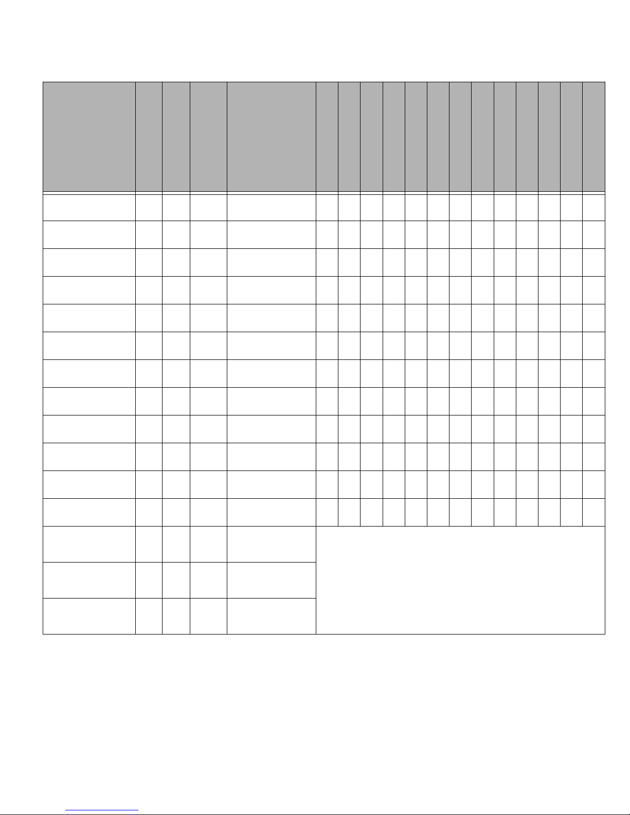
Product Specifications & Capabilities Chart
The table below gives a generalized overview of the specifications and features of a ZMax Relay Cabinet. In the table, the following abbreviations are used:
Y = Yes
N = No
O = Optional
* = An asterick in any column indicates that there is support for this feature, however,
there are conditions with which you should be aware. Consult the specific sections of
the manual dealing with this feature for additional information and requirements.
Page 2
Page 13
Overview Product Specifications & Capabilities
Z-Max Product
Type
Min-Max Relays
Relay Types
Weight (lbs (Kg))
Master Panel, 8 relays 0-8 Any 16
Master Panel, 24 relays 0-24 Any 44
Master Panel, 48 relays 0-48 Any 65
Basic Panel, 8 relays 0-8 Any 16
EZ-Max, 4 Standard
relays
EZ-Max, 4 2-Pole relays 4 2PL 10.6
EZ-Max, 4 347V relays 4 347 10.6
Remote, 4 Standard
relays
Remote, 4 2-Pole relays 4 2PL 10.6
4Std10.6
4Std10.6
(7.26)
(19.96)
(29.48)
(7.26)
(4.83)
(4.83)
(4.83)
(4.83)
(4.83)
Size
W", H", D"
(Wcm,Hcm,Dcm)
13" x 13" x 4-9/32"
(33 x 33 x 10.9)
20-1/4"x34"x4-9/32"
(54.4 x 86.4 x 10.9)
20-1/4"x54"x4-9/32"
(54.4 x 86.4 x 10.9)
13" x 13" x 4-9/32"
(33 x 33 x 10.9)
10" x 10" x 4-9/32"
(25.4 x 25.4 x 10.44)
10" x 10" x 4-9/32"
(25.4 x 25.4 x 10.44)
10" x 10" x 4-9/32"
(25.4 x 25.4 x 10.44)
10" x 10" x 4-9/32"
(25.4 x 25.4 x 10.44)
10" x 10" x 4-9/32"
(25.4 x 25.4 x 10.44)
Flush Mount Option
# Discreet Inputs
Opt. Swt In Board
Luma-Net Network
DMX Network
Master/Slave Net
Emergency Input
Emergency Output
Touch-Tone Phone
Data Modem
Ethernet Network
Front Panel Program
Event Scheduler
Y8NYYYYYO*O*O*YY
Y1236YYYYYO*O*O*YY
Y1236YYYYYO*O*O*YY
Y8NNNNNNO*O*NYY
N6*NNNN YNO*NNY Y
N6*NNNN YNO*NNY Y
N6*NNNN YNO*NNY Y
N4 NNNY Y YNNNNN
N4 NNNY Y YNNNNN
Remote, 4 347V relays 4 347 10.6
Remote, 24 Max Relays 0-24 Any 44
Remote, 48 Max Relays 0-48 Any 65
Z-Max with Breakers,
120V Cabinets and 48
Master or Remote Panel
Z-Max with Breakers,
120V Cabinets and 24
Master or Remote Panel
Z-Max with Breakers,
277V Cabinets and 48
Master or Remote Panel
0-48 Any 195
0-24 Any 174
0-48 Any 335
(4.83)
(19.96)
(29.48)
(88.45)
(78.93)
(152)
Figure 5: General Product Capabilities Chart
10" x 10" x 4-9/32"
(25.4 x 25.4 x 10.44)
20-1/4"x34"x4-9/32"
(54.4 x 86.4 x 10.9)
20-1/4"x54"x4-9/32"
(54.4 x 86.4 x 10.9)
24"x87"x4-9/32"
(61 x 220 x 10.9)
24" x 67" x 4-9/32"
(61 x 170 x 10.9)
60" x 40-1/2" x 6"
(152 x 103 x 15.2)
N4 NNNY Y YNNNNN
Y1236NNY Y YNNNNN
Y1236NNY Y YNNNNN
Features are defined based on the Z-Max relay cabinet to which it is paired
Z-Max Advanced Programming & Systems Design Guide rac00-sdg
Revision A:11/2005 Page 3
Page 14

Warnings - READ ME FIRST
• Conduit Entry Locations: The cabinets have been designed with specific locations
supporting conduit entry for line and low voltage circuits. There are specific areas
of the cabinet which are restricted from some or all types of conduit access.
Reference the Physical Installation section of this manual for specific details.
• Line & load circuit wiring: The line wiring should come from an over-current device
and the load circuit wiring shall go to the specific load to be controlled. On some
models which have integrated branch circuit protection, the line side of the relay
has been pre-wired to a circuit breaker. With these products, only the load side of
the circuits needs to be connected.
• To be installed and/or used in accordance with appropriate electrical codes and
regulations.
• To be installed by a qualified Electrician.
• DO NOT CONNECT line voltage wires to low voltage terminals.
• Mount in a location where audible noise is acceptable.
• When using with fluorescent ballasts, both lighting fixture and ballast must be
grounded.
• Use this relay cabinet only with minimum 75
• Disconnect power when servicing the relay cabinet, fixture or when changing
lamps.
• Indoor use only.
• TO AVOID FIRE, SHOCK OR DEATH: TURN OFF POWER AT MAIN CIRCUIT
BREAKER, OR FUSE, AND TEST THAT THE POWER IS OFF BEFORE WIRING,
OPENING THE PANEL, OR REPLACING ANY COMPONENT!
• During operation, cabinet cover is to be removed by qualified personnel ONLY!
Heed all caution markings indicating the presence of High Voltage. High voltage
may be up to 600V.
• Test each circuit for short circuits before connecting it to relay so damage to the
relay and it’s electronics can be avoided.
• Verify that all un-used power supply leads are insulated with wire nuts.
o
C copper wire at 75% ampacity.
Page 4
Page 15

Part I - Front Panel Operation & Visual Status
Your relay panel has many unique operational features which can be accessed directly
from the front panel. Relay control, relay overrides, and basic status information are
all available features. Secondly, both internal and external to your relay panel are
several "status" indicators which will assist you in determining how your panel is
operating and whether or not it is operating properly. This part of your guide
addresses both of these topics.
Z-Max Advanced Programming & Systems Design Guide rac00-sdg
Revision A:11/2005 Page 5
Page 16

Page 6
Page 17
Setting the Date, Time, & Astronomical Time Clock
The AM/PM desi
Setting the Date, Time, & Astronomical
Time Clock
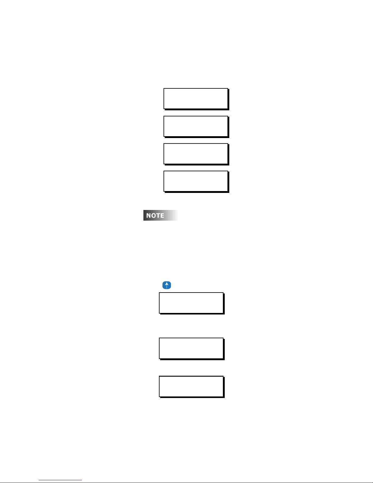
The menu structures for the set date, time, and astronomical clock are as follows:
MON 02:37P UE001
STATUS: NORMAL
MAIN MENU SELECT
TIME/DATE/ASTRO
TIME/DATE/ASTRO
SET TIME & DATE
TIME/DATE/ASTRO
SET ASTRO CLOCK
gnation directly following a time
value has a specific meaning: A/P - indicates you
are in daylight savings time; a/p indicates
standard time; s/d indicates you’re in 24 hour
mode.
Set the Date & Time
Step 1: Press the Menu button
Step 2: Press until the display reads as below then press Select/Save:
MAIN MENU SELECT
TIME/DATE/ASTRO
Step 3: To set the time, press UP until the display reads as below, then press
Select/Save:
TIME/DATE/ASTRO
SET TIME & DATE
Step 4: You now will see the screen below:
08:33PM FRI 12H
04/15/2005 D:OFF
• Hours
• Minutes
• AM/PM
Z-Max Advanced Programming & Systems Design Guide rac00-sdg
Revision A:11/2005 Page 7
From this screen, the following can be edited
Page 18
• 12H or 24H
• Month
• Date
• Year
• Daylight Saving Time
• OFF - Daylight savings time is disabled
• US - Daylight savings time is set to "United States" daylight savings mode,
with 1 hour adjustment in the fall and spring.
• EU - Daylight savings time is set to "European" daylight savings mode with
1 hour adjustments in the fall and spring, yet different dates then the US
• US7 - Daylights savings time is set to "United State" daylight savings mode
which is currently scheduled to become active in 2007 per the new Energy
Conservation act
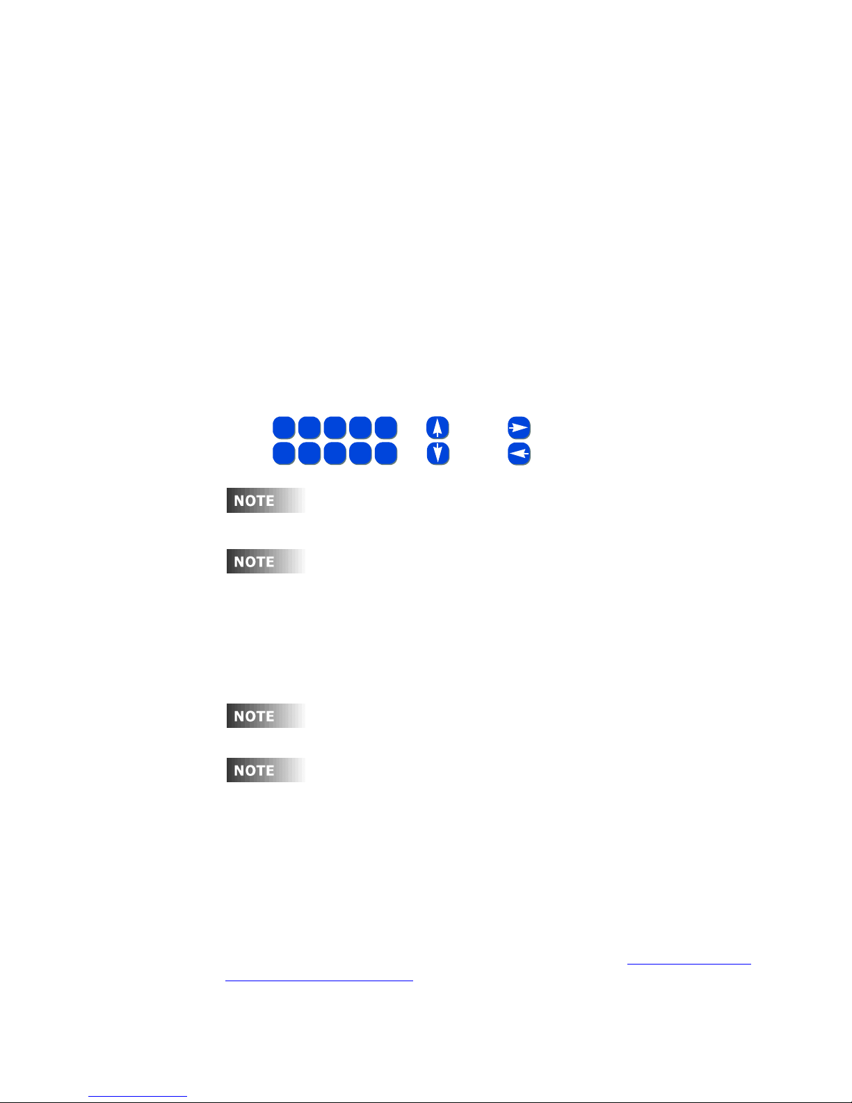
The editable field will be flashing. As always, use the following keys
FOR FIELD VALUE CHANGES
{
ABC3DEF4GHI
1-2
MNO7PQRS8TUV9WXYZ
6
To the right of the time field, the day of the week is displayed. This
field is not editable and is set based on the date setting.
JKL
5
SPACE
0
OR
FOR FIELD
NAVIGATION
AND
When 12 hour mode is active, the AM/PM field is active for editing. If
Daylight Savings Time is active, the field will display in upper case
characters. If Daylight Savings Time is inactive, the field will display
in lower case characters. If 24 hour mode is active, the AM/PM field
is replaced with an “s” or a “d” and is not editable. Instead, the value
is determined by the Daylight Savings Time setting. The “s” indicates
standard time (Daylight Savings Time inactive); the “d” indicates that
Daylight Savings Time is active.
If Daylight Savings time is active, the am/pm will be displayed in
Upper case letters.
If you exit from this menu via the MENU or CANCEL button, all
changes will be lost.
Set the Astronomical Time Clock
The Z-MAX Scheduler allows you to turn lights on or off in relation to sunrise and
sunset. For example, yard lights can be set to turn on an hour before sunset, and turn
off an hour after sunrise, according to the time of year.
The astronomical time clock (Astro Time) calculates the time of sunrise and sunset for
every week of the year depending on the location of the installation. To use Astro
Time you must know the approximate latitude (in degrees) (See Appendix A for
various cities in North America) of the controller’s location, as well as the present time
of sunrise and sunset (often found in the daily newspaper). Visit www.srrb.noaa.gov/
highlights/sunrise/sunrise.html for a complete listing of Latitude, Longitude, Sunrise
and Sunset information.
Page 8
Page 19
To set up the astronomical clock:
Latitud
t
Step 1: Press the Menu button
Step 2: Press until the display reads
MAIN MENU SELECT
TIME/DATE/ASTRO
then press Select/Save
Step 3: To set the time, press UP until the display reads
TIME/DATE/ASTRO
SET ASTRO CLOCK
then press Select/Save
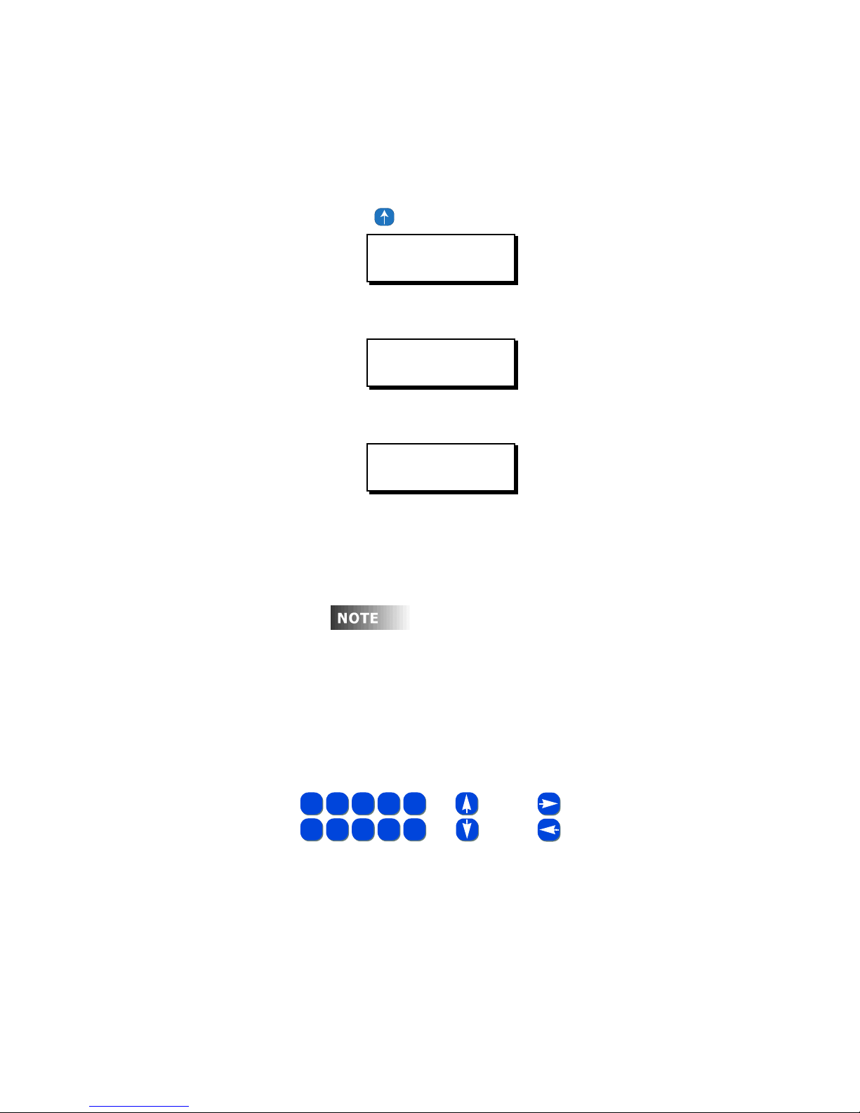
Step 4: You now will see the screen below:
SR=07:01A
SS=08:25P LAT=45
Set the Date & Time
From this screen, the following can be edited
• SR=Sunrise time of any day this week
• SS=Sunset time of any day this week
• LAT=approximate Latitude of the current location
e should be rounded to the neares
multiple of "5" to your location. This is normal.
Sunrise and sunset times can be found in your
local newspaper, by calling our technical services
department, or at http://www.sunrisesunset.com
Step 5: The editable field will be flashing. As always, use the following keys
FOR FIELD VALUE CHANGES
{
ABC3DEF4GHI
1-2
MNO7PQRS8TUV9WXYZ
6
JKL
5
SPACE
0
OR
FOR FIELD
NAVIGATION
AND
Z-Max Advanced Programming & Systems Design Guide rac00-sdg
Revision A:11/2005 Page 9
Page 20

Page 10
Page 21

Visual Status and Operational Feedback System Status LED’s
Visual Status and Operational Feedback
What are all these blinking lights?
Your Z-MAX relay cabinet has a variety of feedback mechanisms which are designed
to alert you as to how your panel is operating and the current status of each relay.
The main feedback mechanism, the LCD display is covered at the beginning of the
“User Interface” chapter. The feedback mechanisms we’re discussing here cover all
of the red, amber, or green LED’s inside the panel.
The LED’s inside the panel can be broken up into two categories, ‘System Status’ and
‘Relay Status’ LED’s.
System Status LED’s
System Status LED’s are designed to tell you at a quick glance the operational
characteristics of your system. For example, whether or not your system is receiving
data on one of the communication lines! This will assist you and our technical support
team should any diagnostics be necessary.
Use the following table to determine the possible colors and patterns of the LED’s
which represent their status.
Generally, the following conventions apply:
• Green – All Systems Go! No alerts detected.
• Flashing Green – All Systems Go! Receiving or transmitting data.
• Solid Red – Alert Condition. Specific alert depends on LED
• Slow Flashing Red – Systems operating Normally, usually a heartbeat
• Quick Flashing Red – Alert Condition or Override Condition, specific alert depends
on LED.
The specific functions and states of each LED are listed below:
Z-Max Advanced Programming & Systems Design Guide rac00-sdg
Revision A:11/2005 Page 11
Page 22
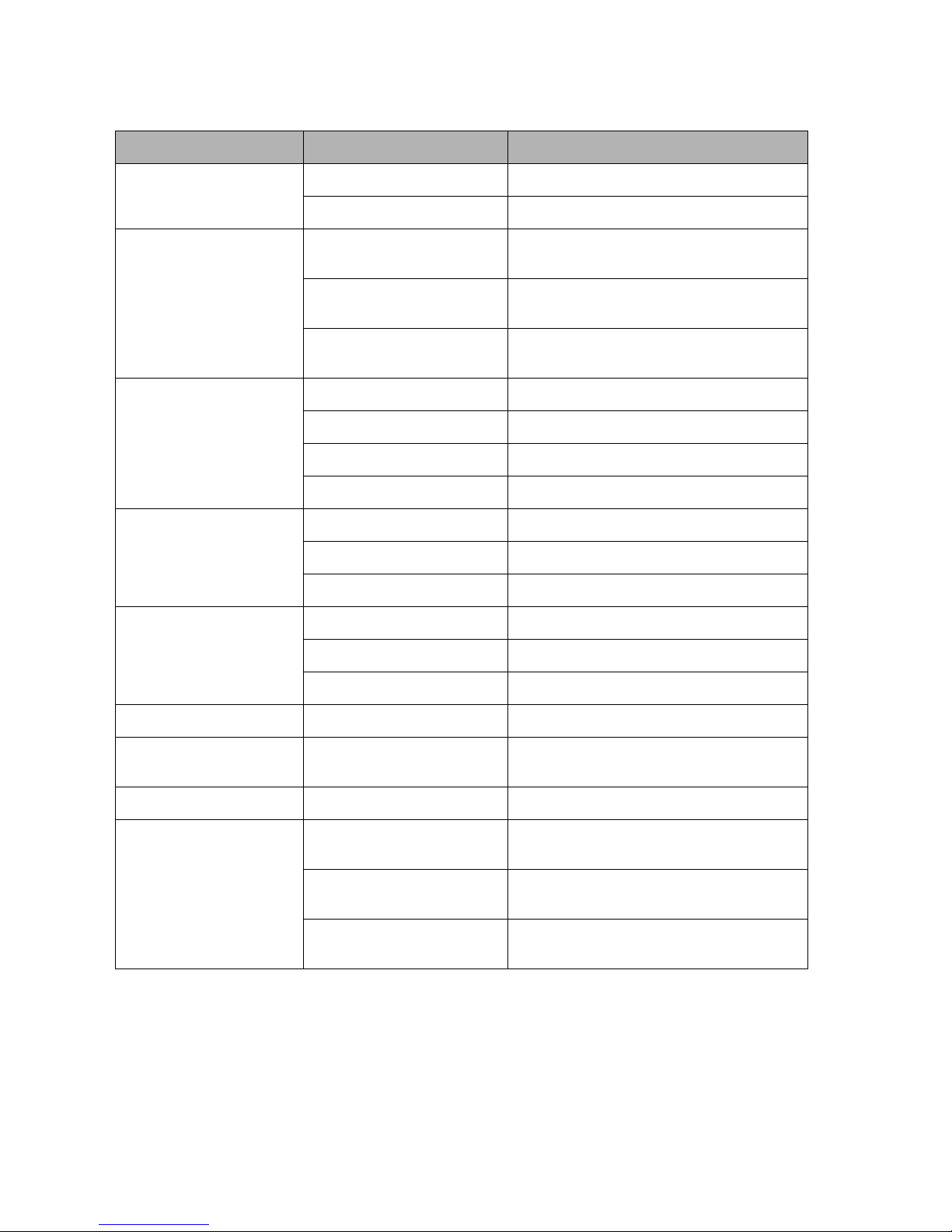
LED Label LED State Indication
EMERGENCY Solid Red Indicates system is in emergency state
Off System is in Normal State
HEARTBEAT-C Slow Blinking Amber
(~1 bps)
Fast Blinking Amber
(~2 bps)
Control Module Microprocessor is operating
properly
Control module microprocessor is in boot
mode
Off Control Module Microprocessor off line -
usually indicates system failure
Luma-Net Solid Green Configured (Negotiating a connection)
Off Disabled
Fast Flash Negotiating connections/initialization
Slow Flash Connected, TX/RX data
DMX Blinking Mostly On Receiving Valid DMX Data
Solid DMX enabled but no data receive
Off Either Disabled or Not receiving Valid Data
CAN 1 (Master/Remote) Blinking Green Enabled, Receiving Data
Solid Green Enabled, but not currently receiving data
Off
CAN 2 N/A Not currently in use
ETH/MODEM Solid Green Indicates modem or ethernet module is
installed, enabled, and link is established
5V POWER Solid Amber +5V power supply working normally
HEARTBEAT-R Slow Blinking Amber Relay Communications Microprocessor
operating properly
Fast Blinking Amber Relay Communications Microprocessor
detects a hardware alert
Off Relay Communications Microprocessor Off
Line
Page 12
Page 23
Visual Status and Operational Feedback System Status LED’s
Relay Status LED’s
Adjacent to each relay switch you will find an LED which indicates the current status
of that particular relay card.
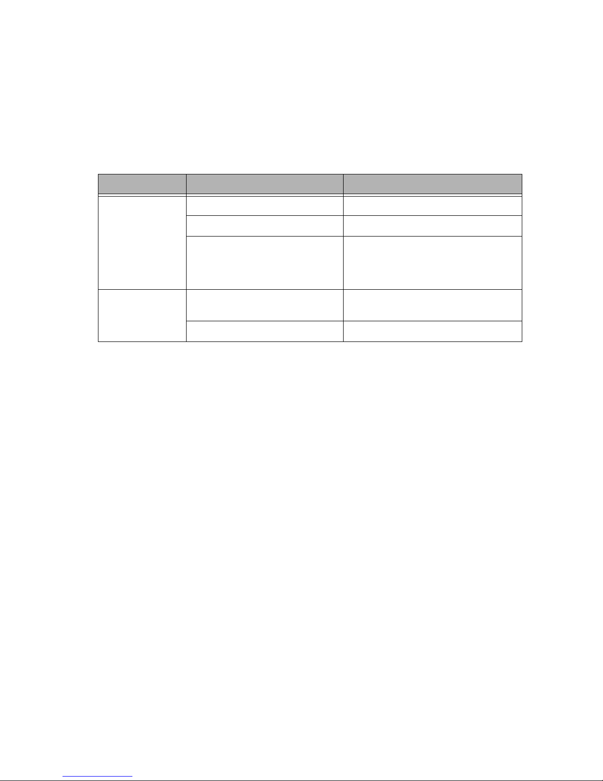
The possible states for this LED are as follows:
LED Label LED State Indication
RELAY X Solid Green Relay On
Off Relay Off
Blinking Green Relay Override On, could be either local
relay override, or if all relay LED’s are
blinking slowly more likely the master
override is On
All RELAYS All Relay LED’s
Short Off Long On
All Relay LED’s, Long Off, Short On Master Override/Bypass Off
Master Override/Bypass On
Z-Max Advanced Programming & Systems Design Guide rac00-sdg
Revision A:11/2005 Page 13
Page 24

Page 14
Page 25
Determine the Firmware/Software Build
Determine the Firmware/Software Build
Knowing the current version of the operating software in your cabinet is helpful when
communicating with the factory about problems with your cabinet or checking against
the software version on the website to ensure that you have the latest software.
Leviton recommends checking our website www.leviton.com
periodically to ensure that you always have the most current
software in your relay cabinet.
The Software version is one of the available menu options directly off of the main
menu
Step 1: Press the Menu button
Step 2: Press until the display reads:
MAIN MENU SELECT
SOFTWARE BUILD
Step 3: Press Select/Save
The display will now show you the version of firmware the unit is
running.
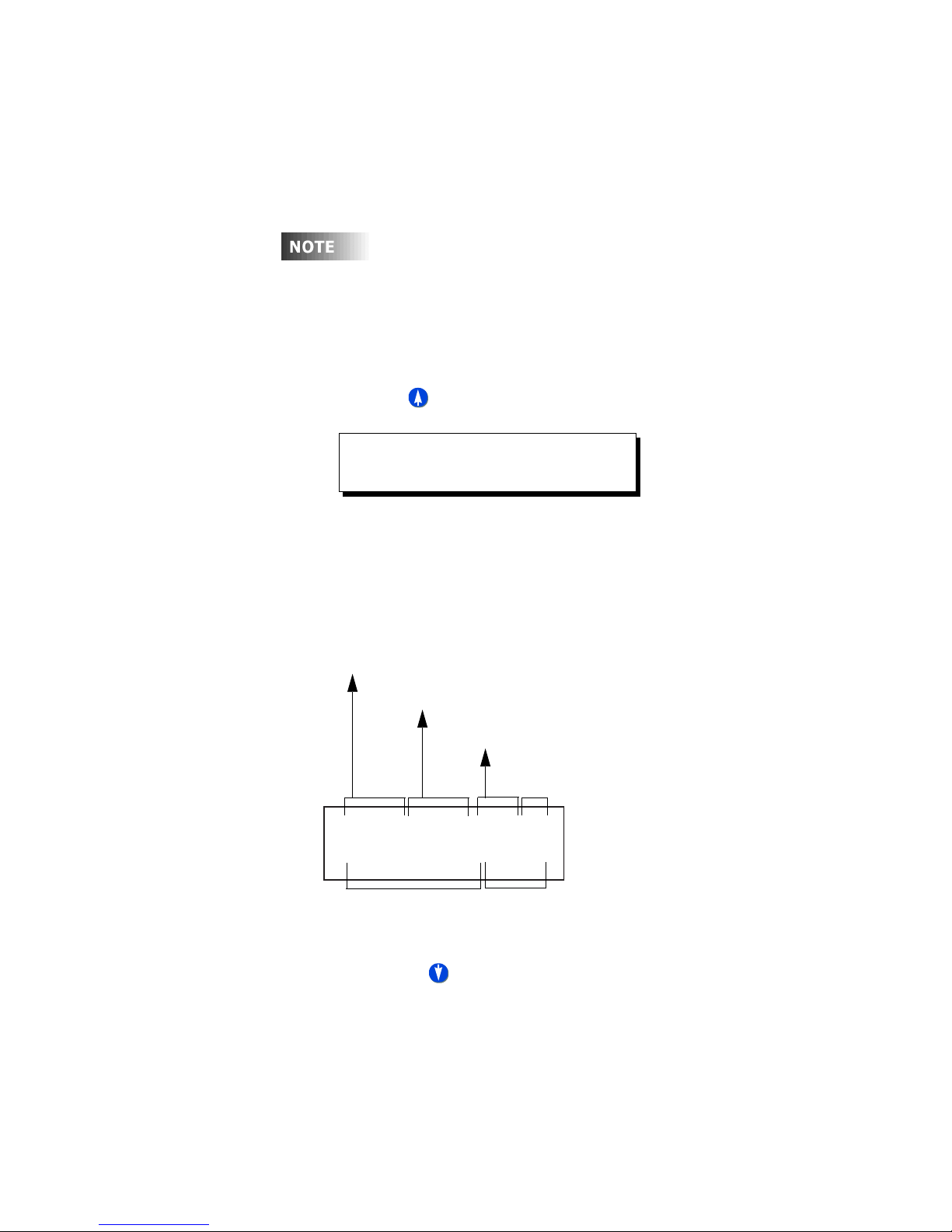
How to Decipher the software Build:
Processor
Speed
Firmware
Version
Database
Version
24MHzV1.04/001SM
30JUL041651IDPAS
Build Date and Time
Luma-Net State (Passive or ID#)
(not applicable to all models)
Cabinet
Typ e
Step 4: Pressing in this screen will show you similar screens, indicating
Z-Max Advanced Programming & Systems Design Guide rac00-sdg
Revision A:11/2005 Page 15
similar software/hardware information regarding other hardware
components in your relay cabinet. This information may be useful when
diagnosing problems with your relay cabinet or with the relay cards,
modem, eithernet, or switch input board modules.
Page 26

Page 16
Page 27

Touch-Tone Telephone Interface
R
Configuration of your touch-tone telephone interfaces requires carefully setting up
security/passcodes as well as several configuration items relating to the modem itself.
These processes are covered in detail in the Advanced Configuration Guide. This
chapter outlines the user operation of the interface.
The touch-tone interface, TIM, allows for control of groups at one of many security
levels over the telephone. Regardless of the "Mode" of operation which is applicable,
the following keys and indications are valid
• # key is must be pressed at the conclusion of every entry
• * starts over the entire process as if you just called into the panel
• *# immediately signals the panel to terminate the phone call. (Note that at any
time you may hang up your phone and the communication will be terminated)
• After every command, a series of beeps will indicate that the command was
completed
• 1, 2, or 3 short high beeps usually indicate successful execution
• 1 quick high beep followed by a long low beep indicates command failure or
incorrect data entry
• 1 long low warbling beep indicates that the panel is about to disconnect the
call.
Using the TIM requires the following steps:
Step 1: Call your relay panel, wait for it to answer, and wait for (3) short beeps
Step 2: Enter your password followed by the pound (#) key
Step 3: Hear (2) short beeps indicating command or user mode, or (1) short
beep indicating admin mode
Step 4: One of the three modes below are entered
Command Mode
If your password is associated with Command mode, upon successful password entry
the command is executed and the panel hangs up. All functionality of command mode
passwords are completely configured by the system administrator.
User Mode
In user mode, you have complete control over a single "Group" of relays as defined by
the panel administrator.
emember that each relay can belong to one or
more Groups; groups are global meaning that
any network panel which receives a group
command will activate it’s relays assigned to
those groups. This allows a simple way of total
system control, from the touch tone interface.
Z-Max Advanced Programming & Systems Design Guide rac00-sdg
Revision A:11/2005 Page 17
Page 28

After the two short beeps are heard (step 3 above), any of the following commands
can be entered, followed by the pound (#) key:
• 0 - Turn group off at normal priority, all other actions can override
• 1 - Turn group on at normal priority, all other actions can override
• 2 - Turn group on at high priority, most other actions can not override
• 3 - Turn group On at normal priority only for a defined period of time (defined by
your administrator)
• 7 - Relinquish control of the group to all other actions and controlling sources
• 8 - Turn group off at high priority, most other actions can not override
• 9 - Turns group Blink Warn Off at normal priority
• 10 - Cancels blink warn for this group at normal priority
Administrator Mode
In administrator mode, you have complete control over all "Groups" of relays as
defined by the panel administrator. You know that you’re in administrator mode
because after entering your password, you hear 1 beep instead of two.
In administrator mode, the complete process is as follows:
Step 1: Call your relay panel, wait for it to answer, and wait for (3) short beeps
Step 2: Enter your password followed by the pound (#) key
Step 3: Hear (1) short beep indicating admin mode
Step 4: Enter one of the following commands, followed by the pound (#) key:
• 0 - Turn group off at normal priority, all other actions can override
• 1 - Turn group on at normal priority, all other actions can override
• 2 - Turn group on at high priority, most other actions can not override
• 3 - Turn group On at normal priority only for a defined period of time
(defined by your administrator)
• 7 - Relinquish control of the group to all other actions and controlling
sources
• 8 - Turn group off at high priority, most other actions can not override
• 9 - Turns group Blink Warn Off at normal priority
• 10 - Cancels blink warn for this group at normal priority
Step 5: Hear (2) short beeps indicating that the command is valid
Step 6: Enter a group number followed by the pound (#) key
Step 7: Hear (2) short beeps indicating that the command was executed
Step 8: Repeat steps 4, 5, 6, & 7 or hand up to terminate the call.
Page 18
Page 29

Part II - Simple Mode Programming
Your relay cabinets contain two modes of programming: simple, and advanced.
Simple mode is designed to give you a very simple, question & answer means of
programming your relay panel but only gives you access to a limted feature set of
your product. Advanced mode programming in the next part gives you access to the
full capabilities of your relay product.
Z-Max Advanced Programming & Systems Design Guide rac00-sdg
Revision A:11/2005 Page 19
Page 30

Page 20
Page 31

Configuration the Simple Way Panel Configuration in Simple Mode
Configuration the Simple Way
Your relay panel has two modes of configuration, Simple Mode and Advanced Mode.
The default configuration mode is called Simple Mode and is designed to be a less
complex streamlined mode for configuring and operating your relay panel. Simple
mode differs from advanced mode in that many of the advanced features and
configuration items have been removed from the menu structures. Additionally, all
configuration is more question and answer based allowing for more self-navigation
without dependence on this manual.
Changing Configuration from either simple mode to advanced
mode, or from advanced mode to simple mode will never result
in loss of configuration information. This can be used to your
and the end-users advantage by first making all required
configuration settings, then changing the panel configuration
mode to Simple Mode. This will allow the user to make basic
changes, but prevent them from making potentially dangerous
configuration changes.
The following configurations and configuration changes can be performed when the
panel is in simple mode:
• Setup the Time Clock Date, Time, and Astronomical Time Clock Settings
• Add & Change Scheduled Events
• Configure Inputs, Devices connected to inputs, and relays assigned to inputs
• Change Configuration Mode
All other configuration options must be defined in Advanced Configuration Mode.
Panel Configuration in Simple Mode
Configuration of your relay panel by simple mode is really a simple process. (pun
intended) The steps are as follows:
Step 1: Install your cabinet and terminate all power and control wiring
Step 2: Configure your inputs
Step 3: Configure any scheduled events
These three steps of course will vary greatly depending upon your particular
installation so generalized instructions are provided here to help you learn what some
of the functionality is. The next few pages will show you how to configure a low
voltage switch, a photocell, and then an occupancy sensor. That will cover step 2.
Step 1 has already been covered in prior chapters. Step 3 illustrates the methods used
to create and schedule events, or rather relays turning on or off at a specific time.
Z-Max Advanced Programming & Systems Design Guide rac00-sdg
Revision A:11/2005 Page 21
Page 32
Simple Mode Menu Structure
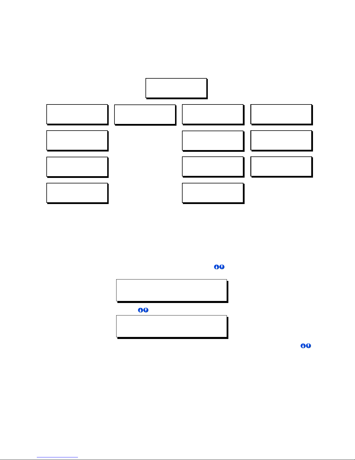
For your reference as you are navigating through the menus, please find below the
complete simple mode menu structure:
MON 02:37P LE001
STATUS: NORMAL
MAIN MENU SELECT
QUICK SCHEDULE
QUICK SCHEDULE
NEW EVENT
QUICK SCHEDULE
CHANGE EVENT
QUICK SCHEDULE
DELETE EVENT
Changing Configuration Modes
Changing configuraiton modes is a simple process. To change from simple to
advanced, or from advanced to simple, please follow the steps below:
MAIN MENU SELECT
SOFTWARE BUILD
Step 1: Press the Menu button, then use until the display reads as shown
below, then press SELECT:.
MAIN MENU SELECT
CONFIGURATION
CONFIGURATION
CONFIG INPUTS
CONFIGURATION
MODE: SIMPLE
CONFIGURATION
FACTORY DEFAULTS
MAIN MENU SELECT
TIME/DATE/ASTRO
TIME/DATE/ASTRO
SET TIME & DATE
TIME/DATE/ASTRO
SET ASTRO CLOCK
Page 22
MAIN MENU SELECT
CONFIGURATION
Step 1: Use until the display reads as shown below, then press SELECT:.
CONFIGIRATION
MODE:SIMPLE
Step 2: You will now notice that the
to select either
configuration mode has now been changed.
Simple
or
Advanced
Mode
line of the display is blinking. Use
, then press SELECT. Your
Page 33
Configuration the Simple Way Configure Inputs
T
Configure Inputs
here are three types of inputs which can be
configured in your relay cabinet, Low Voltage Switch
Inputs, Photocell Inputs, and Occupancy Sensor
inputs. All Inputs are configured from the Config
Inputs Screen which falls into the menu structure as
shown as right. Each of the three types of inputs are
then configured from their own menu.
MON 02:37P E:001
STATUS: NORMAL
MAIN MENU SELECT
CONFIGURATION
CONFIGURATION
CONFIG INPUTS
CONFIGURATION
OCC SENSOR
CONFIGURATION
PHOTOCELL
CONFIGURATION
LV SWITCH
Low Voltage Switch Inputs
Configuration of this type of input is used when you have some type of switch or
other triggering device connected to one of the inputs from which you desire to turn
on or off relays. Several different behaviors are available for configuring of this type
of input.
CONFIG INPUTS
LV SWITCH
Step 1: From the main menu, navigate to Configuration, Config Inputs, then LV
Switch.
Remember that when navigating menus, pressing Select
always selects the current menu, and pressing Cancel always
navigates to the previous menu.
Step 2: Enter the input number of the switch input you wish to configure. This is
determined by looking at the terminal on your cabinet to which the
switch is connected. After entering the number, press the Select key
Step 3: The relay panel now asks for a behavior:
Z-Max Advanced Programming & Systems Design Guide rac00-sdg
Revision A:11/2005 Page 23
ENTER LV SWITCH
INPUT NUMBER:002
SELECT BEHAVIOR
MOMENTARY
Your selection for the behavior of your switch will be determined by
the type of switch you have and how you desire it to operate. The
available behaviors are as follows:
• Momentary - The first press turns on the assigned relays, the second press
turns off the assigned relays
Page 34

• Momentary Timed - Upon the first press, turn on the assigned relays for
the specified amount of time. When the time elapses, control of the relays
is relinquished to other controls (which generally results in the relays
turning off.) If the switch is pressed a second time, the timer is reset.
To specify the amount of time used for timed inputs, change
configuration mode to Advanced, go to System Setting under
the configuration menu, then Global Defaults and change the
Tswit value. Valid settings are 1-254 minuntes
• Maintained - Maintained inputs turn On the relays while the switch is
pressed, then turn off the relays when the switch is released
• Preset Off - Turns off all relays in the current preset group.
• Preset On - Turns on all relays in the defined preset group.
• Momentary On/Off - Momentary On/Off is used with switch inputs
connected to switches that have separate on & off outputs and in
coordination with our switch input adapter cards or switch input adapter
kits. These kits provide both the on and off signal on the same switch leg
AND require the switch input setting to be defined as Momentary On/Off
Step 4: This optional step only applies when using the Preset On/Off Types
ASSOCIATE PRESET
NEW NUMBER: NO
• Z-MAX panels use associate preset groups to define the group of buttons
that are all a part of the preset group. All inputs that are part of the same
group number work together and only one of the inputs can be active at
any one point in time.
• If you have already defined a number for the group to which this input
belongs, select NO at this prompt and select the number.
• If you have not defined an associate preset group number or need to
create a new group, select YES at this prompt and then enter the new
number.
Step 5: Relay assignment - There are two methods which can be used to assign
relays to switch inputs, "Quick" and "Menu."
• Quick method allows you to assign relays to this input by pressing the
override button adjacent to the relay. Note that only the LED indicates
status, relay state does not change.
Page 24
Page 35
Configuration the Simple Way Configure Inputs
As the "quick"
• Menu method allows you to use the up/down arrow or number keys to
select the relays you wish to assign, and left/right to choose the state.
relay assignment method involves
access to the override buttons which requires
opening your relay panel, this programming
method is only appropriate for both authorized
and trained personnel as dangerous voltages are
present inside your relay cabinet.
Use
to
select your relay assignment method:
ASSIGN RELAYS
MODE: QUICK
Step 6: If Quick Assignment Mode was selected, use the override buttons
adjacent to each relay to set whether that relay should be on or off. In
this programming mode, the relay will not change state, however, the
LED adjacent to each relay will light on or off matching the state of the
real as assigned to the input.
Step 7: If Menu Assignment Mode is selected, the relays which should be
controlled by this input can be selected by using the following keys
• Use to increase or decrease the relay number
•
• Use to select any of the possible three actions for this relay
•ON - turns this relay on when the switch is pressed
•OFF - turns this relay off when this switch is pressed
•IGNORE - instructs the relay panel to not change the state of this
relay when the switch is pressed
Step 8: Press Save/Select to save your settings and complete
configuration of this input.
Photocell Configuration
Photocells are used with relay panels to control the switching on and off of relays
relative to the amount of light received by the relay panel. Two types of photocells are
supported by your relay panel, called switching and 0-10V. Switching photocells
interact with your relay panel just like a switch. They output a low voltage signal to
the relay panel when the amount of light received by the photocell crosses a pre-set
threshold. 0-10V photocells output 0-10V, proportional to the amount of light
received. Switching photocells must be configured to trip at a specific level which is
also appropriate for your project. 0-10V photocells must be optimized for the range of
lighting levels to which the photocell is intended.
Z-Max Advanced Programming & Systems Design Guide rac00-sdg
Revision A:11/2005 Page 25
Page 36

Step 1: Using the menu navigation buttons, navigate the menus to Configuration,
Config Inputs, then to Photocell, and press Select/Save
CONFIGURATION
PHOTOCELL
Step 2: Enter the Input Number. Usually a photocell is connected to the PhotoCell
input and the screen would read as follows
ENTER PHOTOCELL
INPUT NUMBER:PC
Step 3: Select Photocell Behavior
SELECT BEHAVIOR
FORCE OFF
• Force Off - The photocell will be turning off
voltage, usually indicating that the photocell is receiving more light. The
trigger to turn on the relays must be from another source, like the
scheduler or a switch. This application is useful for parking lot lighting
which is turned on by the scheduler and off during the day.
• Force On/Off - The photocell will be turning on and off relays and no other
source (at the current or lower priority level) will be able to alter this
condition. This behavior is appropriate for applications where the photocell
will be the only controlling source for the relays.
• Force On - The photocell will only be turning on lights and some other
control will turn off the lights. This behavior is appropriate when lights
must be on when it’s dark, but only turned off by a switch, building sweep,
scheduler, switch, or other control device.
Step 4: Enter the delay time. This is the time between when the photocell
triggers the action and the action actually occurs. Longer delay times are
relays when the input receives
Page 26
Page 37
Configuration the Simple Way Configure Inputs
necessary when false triggering due to rapidly changing lighting
conditions is likely.
ENTER TIME DELAY
DELAY TIME:005
Step 5: Photocell type=0-10V
PHOTOCELL TYPE
TYPE: 0-10V
Step 6: Enter number of fc per volt for your
photocell. For example, if you have a
photocell with range 0-100fc at 0-10V,
that’s 10fc per volt
PHOTOCELL
FC/VOLT=010V
Step 7: Enter fc trigger level, that is when the
relays should turn "on", or rather the
trigger point of the photocell
ENTER FOOTCANDLE
ON FC:085FC
Step 8: Add relays which should be controlled
ASSIGN RELAYS
RELAY 001:YES
• Use or to increase or decrease the
relay number
Step 5: Photocell type=Switching
PHOTOCELL TYPE
TYPE:SWITCHED
Step 7: Add relays which should be controlled
PC RELAYS
RELAY 001:ON
• Use or to increase or decrease the
relay number
• Use to select any of the possible three
actions for this relay
• YES - turns this relay on (or off,
depending on behavior) when the
photocell activates
• IGNORE - instructs the relay panel to not
change the state of this relay when the
switch is pressed
Step 8: Press Save/Select to save your
settings and complete configuration of
this input.
• Use to select any of the possible three
actions for this relay
• YES - turns this relay on (and/or off) when
the switch the trigger point is crossed
• IGNORE - instructs the relay panel to not
change the state of this relay when the
trigger point is crossed
Step 9: Press Save/Select to save your
settings and complete configuration of
this input.
Z-Max Advanced Programming & Systems Design Guide rac00-sdg
Revision A:11/2005 Page 27
Page 38
Occupancy Sensor Configuration
Occupancy sensors are devices which sense when a person enters a particular room
or area. Leviton’s Occupancy Sensor’s are designed for a variety of applications, using
a variety of technologies which can be applied to your specific need. The Occupancy
sensors which this relay panel is designed to work with are those which are powered
by +24Vdc and provide a ~+24Vdc output when the covered area is occupied.
These instructions assume that your Occupancy Sensor is connected to the OCC input.
If your Occupancy Sensor is connected to one of the other inputs, configuration will
be similar.
Step 1: Using the menu navigation buttons, navigate the menus to Configuration,
Config Inputs, then to Occ Sensor, and press Select/Save
CONFIG INPUTS
OCC SENSOR
Step 2: Enter the Input number to which your occupancy sensor is connected. If
connected to the input labeled "Occ Sensor", the input number should be
"OCC"
ENTER OCC SENSOR
INPUT NUMBER:OCC
Step 3: Enable or Disable this occupancy sensor
OCCSEN:001 LOCAL
ENABLED: YES
Step 4: Enter the Behavior of the occupancy sensor
SELECT BEHAVIOR
MANUAL ON
The choices for behavior are as follows:
• Manual On - The occupancy sensor will turn off the assigned relays when
the occupancy sensor indicates an occupied state. When the room become
occupied, the relays will not be automatically turned on, instead, the user
will have to manually turn on the lights from a wall switch or other input.
• Auto On - In this mode, the Occupancy Sensor will turn the assigned
relays both on and off based on either an occupied or unoccupied stated
indicated by the occupancy sensor
Page 28
Page 39
Configuration the Simple Way Configure Inputs
Step 5: If you desire a blink warn to be issued prior to turn turning off the lights,
the response to this question should be Yes. If not, the response should
be No
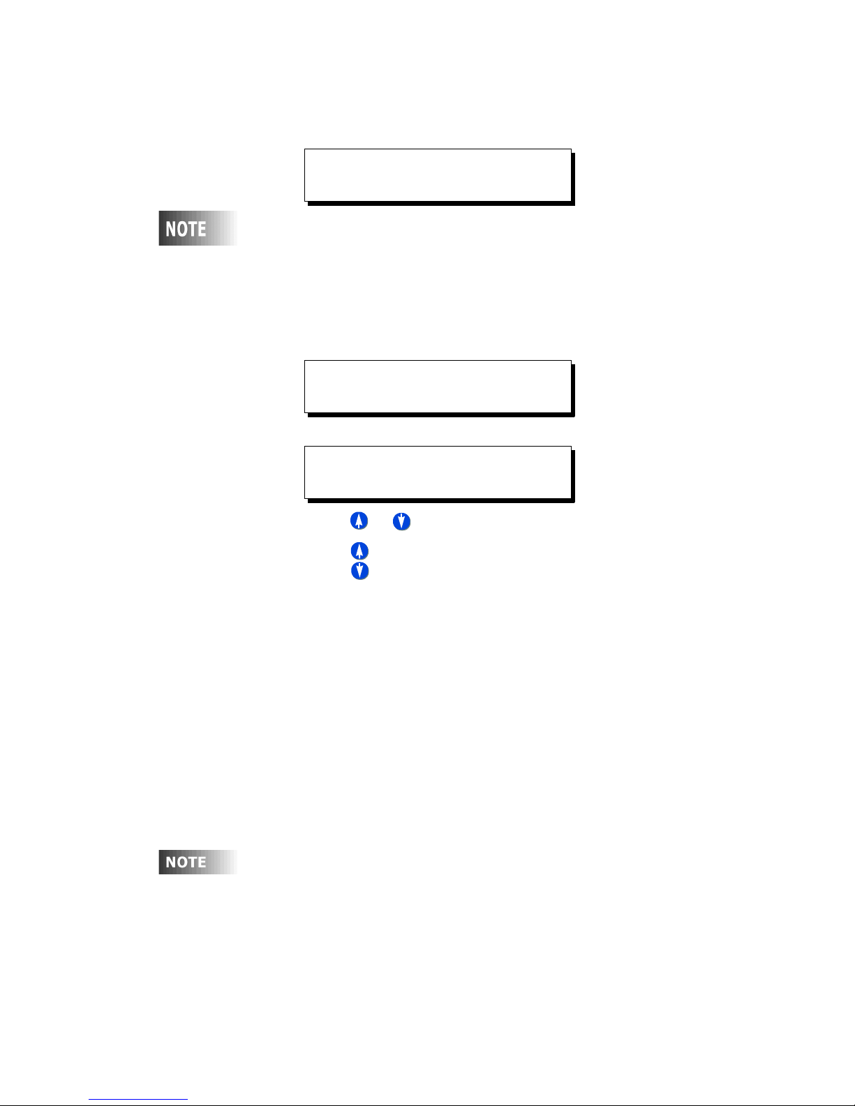
ENTER BLINK WARN
ENABLED: YES
A Blink Warn is not only advisable to keep people from suddenly
being left in the dark but is also required by some authorities
having jurisdiction. When blink warn is enabled, the lights will
"blink" prior to actually being turned off. After the blink, the
user can press the on button to cancel the off, otherwise, the
lights will automatically turn off.
Step 6: Enter the time delay between when the occupancy sensor indicates an
unoccupied state and the relays actually turn off
ENTER TIME DELAY
MINUTES: 000
Step 7: Assign Relays
ASSIGN RELAYS
RELAY:001 YES
• Use or to increase or decrease the relay number
• Use to select any of the possible
actions for this relay
• YES - turns this relay on (and/or off) when the switch trigger point is
crossed
• IGNORE - instructs the relay panel to not change the state of this relay
when the trigger point is crossed
Step 8: Press Save/Select to save your settings and complete configuration of
this input.
Quick Schedule
The quick schedule menus are used to create a new event, change the time of an
existing event, and delete an event. An event is an action which occurs at a time. For
example, Relays 1, 2, & 4 turn ON at 7:30am is an example of an event which might
be schedule in a venue where relays 1, 2, & 4 are connected to lobby lights, when
doors open at 8:00am.
In technical Z-MAX lingo, an "Action" is what actually occurs. In
the case of the above example, the action is relays 1, 2, & 4
turning on. An "Event" is one scheduled occurrence of an
action. In quick schedule programming, both actions and
events are rolled into one seamless programming process.
To create a scheduled event using the quick scheduler:
Z-Max Advanced Programming & Systems Design Guide rac00-sdg
Revision A:11/2005 Page 29
Page 40
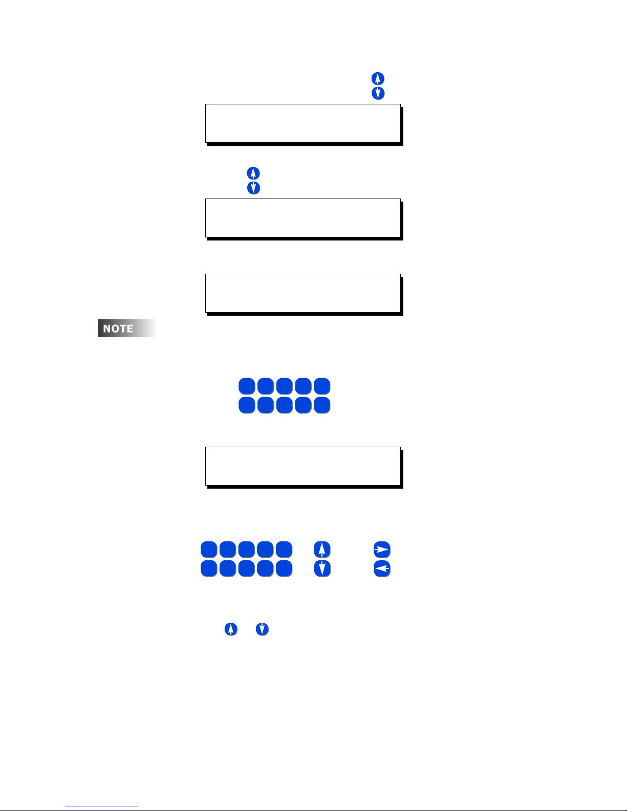
Step 1: Press the Menu button and use until the display reads
MAIN MENU SELECT
QUICK SCHEDULE
then press Select.
Step 1: Use until the display reads
QUICK SCHEDULE
NEW EVENT
then press Select.
Step 2: Enter a name for your event
ENTER EVENT NAME
LIGHTS ON .
Although not required, all events should be given a name which
uniquely identifies both the event itself and gives some sort of
indication of what the event does. This makes modification of
panel programming easy.
OR
OR
JKL
SPACE
5
0
FOR FIELD
FOR FIELD
NAVIGATION
NAVIGATION
AND
AND
ABC3DEF4GHI
1-2
MNO7PQRS8TUV9WXYZ
• Use for alpha-numeric data entry, just like the keys
Step 3: Enter the time the event is to occur
ENTER EVENT TIME
1-2
1-2
MNO7PQRS8TUV9WXYZ
MNO7PQRS8TUV9WXYZ
6
6
• Using or in the am/pm field, will allow you to select
• AM indicating in the morning
• PM indicating in the afternoon
• -SR indicating the specified hours:minutes before sunrise
• +SR indicating the specified hours:minutes after sunrise
• -SS indicating the specified hours:minutes before sunset
6
on your cell phone.
07:30AM .
As always, use
FOR FIELD VALUE CHANGES
FOR FIELD VALUE CHANGES
{
{
ABC3DEF4GHI
ABC3DEF4GHI
Using combinations of the time entry and am/pm fields, there are a
variety of ways to schedule the event:
JKL
JKL
SPACE
SPACE
5
5
0
0
Page 30
Page 41
Configuration the Simple Way Configure Inputs
• +SS indicating the specified hours:minutes after sunset
When done entering the time, press Select
Step 4: Enter the days of the week on which this event is to occur
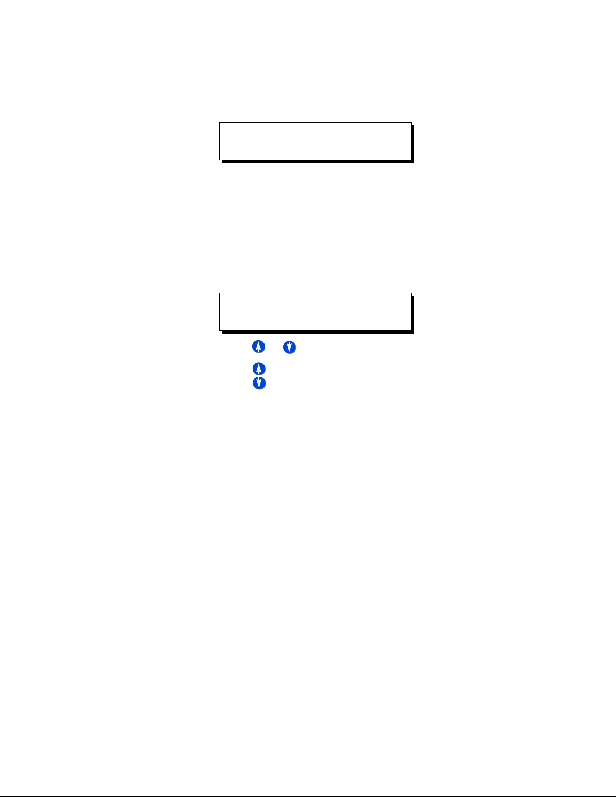
SELECT DAYS
MTWTFSS H1:OFF
• An uppercase day of the week indicates that the event will occur on that
day.
• A lowercase day of the week indicates that the event will not occur on that
day
• H1:ON indicates that the event will occur on any day which is part of the
holiday schedule #1
• H1:OFF indicates that the event will not occur on days which are part of
the specified holiday schedule
Step 5: Assign Relays
ASSIGN RELAYS
RELAY:001 ON
• Use or to increase or decrease the relay number
• Use to select any of the possible three
actions for this relay
• ON - turns this relay on when this event occurs
• OFF - turns the relay off when this event occurs
• IGNORE - instructs the relay panel to not change the state of this relay
when this event occurs
Step 6: Press Select/Save to save your changes.
Z-Max Advanced Programming & Systems Design Guide rac00-sdg
Revision A:11/2005 Page 31
Page 42

Page 32
Page 43
Factory Defaults
Factory Defaults
If it ever becomes necessary to restore the factory defaults and begin the
programming from a clean slate, simply:
Step 1: Press the Menu Button
Step 2: Press until you get to the Configuration Screen
Step 3: Press Select/Save
Step 4: Press until you get to the Factory Defaults Screen
Step 5: Press Select /Save
Step 6: Press once and the N will change to a Y.
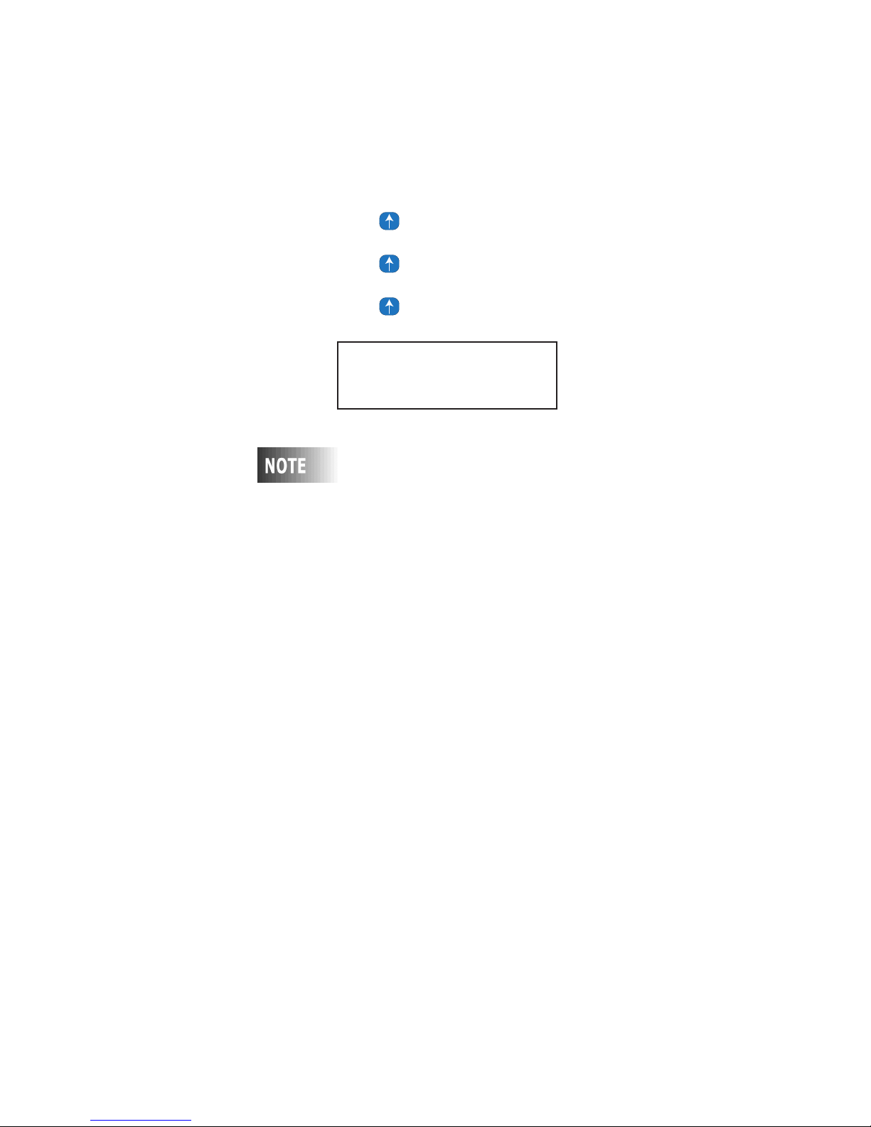
FACTORY DEFAULTS
INITIALIZE ? N
Step 7: Press Select/Save
Resetting to factory defaults will erase any
programming or configuration you’ve completed. Any
parts of this programming you desire to use after the
rest will have to be recreated from scratch
programming in your system.
Saving & Restoring Configuration
Your configuration data can be saved and restored to/from a connected PC using our
PC configuration program. This program is included on the compact disc included with
every cabinet, can be downloaded from our website, or can be ordered from
Customer Service. Leviton recommends that a backup of all cabinet configuration
files be made so that in the unfortunate event of product failure, a quick means by
which to restore configuration is possible.
Z-Max Advanced Programming & Systems Design Guide rac00-sdg
Revision A:11/2005 Page 33
Page 44

Page 34
Page 45

Part III - Advanced Programming Guide
Advanced configuration mode is designed to allow front panel access, operation, and
programming of your relay panel, supporting the full capabilities of the product. This
section of this user’s guide documents the advanced mode configuration menu
structures. Both advanced mode and this documentation assumes that you have
familiarity with the relay panel, relay applications, and a good grasp of the Z-Max user
interface. As such, many of the discussed procedures leave out irrelevant information
and proceed directly to the "meat" of the topic.
If you do not yet have familiarity with the Z-Max relay cabinets and their user
interface, please first review the features and procedures found in the previous part
of this manual addressing Simple Mode Configuration.
Z-Max Advanced Programming & Systems Design Guide rac00-sdg
Revision A:11/2005 Page 35
Page 46

Page 36
Page 47
MON 02:37P E:001
STATUS: NORMAL
Advanced Mode Menu Structure
Advanced Mode Menu Structure
For your reference as you are navigating through the menus, please find below the
top level advanced mode menu structures. Only top-level menus are shown. Some of
the menus have many sub-menus which are detailed in the appropriate sections of
this manual
MAIN MENU SELECT
ACTION EDITOR
MAIN MENU SELECT
SOFTWARE BUILD
MAIN MENU SELECT
TIME/DATE/ASTRO
MAIN MENU SELECT
SCHEDULER
MAIN MENU SELECT
CONFIGURATION
ACTION EDITOR
ADD/EDIT ACTIONS
TIME/DATE/ASTRO
SET TIME & DATE
SCHEDULER
ADD A NEW EVENT
SCHEDULER
IS NOW ACTIVE
CONFIGURATION
SYSTEM SETUP
ACTION EDITOR
DELETE AN ACTION
TIME/DATE/ASTRO
SET ASTRO CLOCK
SCHEDULER
EDIT AN EVENT
SCHEDULER
HOLIDAY EDITOR
CONFIGURATION
FACTORY TESTS
ACTION EDITOR
EXIT (DONE)
SCHEDULER
DELETE AN EVENT
SCHEDULER
EXIT (DONE)
CONFIGURATION
FACTORY DEFAULTS
CONFIGURATION
MODE: ADVANCED
Z-Max Advanced Programming & Systems Design Guide rac00-sdg
Revision A:11/2005 Page 37
CONFIGURATION
INPUTS
Page 48

Page 38
Page 49
Global Defaults
Global Defaults
MENU
GLOBAL DEFAULTS
LOCAL RELAYS 8
MAIN MENU SELECT
CONFIGURATION
The global default menus give you access to many configuration parameters and
options which "globally" affect your relay panel.
Although these settings can help you quickly make changes to your panel, please
make sure that you understand and expect the results. For example, changing the
relay type in global defaults, will automatically and without warning change the relay
type for every relay controlled by this cabinet. As such, any previous changing of relay
type at the relay level will be lost.
CONFIGURATION
SYSTEM SETUP
SYSTEM SETUP
GLOBAL DEFAULTS
Changing the # of Local Relays
Sets the number of local relays in the cabinet. Usually this is set to the maximum
number of relays which can be installed in your relay cabinet. For example, if you
have an (8) relay cabinet, this setting would be 8. If you have a 24 relay cabinet it
would be 24.
The starting relay number for remote relays is dependant upon this setting. The first
remote relay is addressed by the relay number indicated by adding 1 to the number of
local relays. For example, if you have 24 local relays, the first remote relay is 25.
GLOBAL DEFAULTS
RMT RELAYS OFF
GLOBAL DEFAULTS
RMT RLY:*** ID:MAS
Remote Relays
This setting determines the number of remote relays addressed by this relay cabinet
when implementing a Master/Remote network. This should be set to the total number
of relays in all remote cabinets.
For example, if you have (1) 24 remote relay cabinet and (2) 4 remote relay cabinets,
the setting for this entry will be 24+4+4=32 indicating that 32 remote relays will be
controlled by this cabinet.
The relay numbers for remote relays start at 1+the number of local relays. So if you
have 24 local relays, then in this scenario the local relays are 1-24, remote relays 25-
56.
Enable Master/Remote communication
In order for this cabinet to communicate on a master/remote network, the number of
remote relays must be set (see above) and
cabinet. This feature has the following settings:
• OFF - disables Master/Remote communication
• MAS - enabled Master/Remote communication with this as a Master relay cabinet.
Only one master is allowed per network.
this cabinet must be defined as a master
Z-Max Advanced Programming & Systems Design Guide rac00-sdg
Revision A:11/2005 Page 39
Page 50
GLOBAL DEFAULTS
A
lik
L
RMT DISCRETES: Y
•
Any Number
cabinet and this cabinet will participate on the Master/Remote network as a
REMOTE relay cabinet. The starting relay number of this cabinet is shown in place
of the *** on the display
- If a number is selected, this number is the
MRN
number of this
Enable processing of Remote Inputs
If this relay cabinet is a master cabinet on the master/remote network and your
remote relay cabinets have discrete (low voltage) inputs which should be processed
by this master cabinet, this setting should be Y for yes.
• Y - This is a master cabinet and should process remote discrete inputs
• N - This cabinet should not process remote discrete inputs.
GLOBAL DEFAULTS
SEQ. DLY 0.0SEC
GLOBAL DEFAULTS
LEVEL CUT IN 60%
remote discrete input is programmed just
any other input and can be programmed in
either advanced or simple mode. The discrete
input number for remote inputs is the same as the
remote cabinet’s starting relay number.
e
Sequence Delay Time
Use this feature to change the delay time between each relay when turning on a
group of relays. The system allows you to set the value to a 0.0 delay or up to a 25.0
seconds delay for architectural installations where power surges are a concern.
In most applications, a short sequence delay time is appropriate. For example, if the
sequence delay time is set to 0.5 seconds and the relay cabinet is told to turn on
relays 1-4, relay 1 will turn on immediately when the command is executed. Relay 2
will turn on 1/2 second later, relay 3 1 second later, and relay 4 at 1.5 seconds.
Level Cut-In Value
Use this feature to change the threshold value that triggers when the relays turn on
when responding to a control input other than a switch. This is used when the
controls are set up for dimming as well as relays, like a D8000, D4200 or DMX control
device.
Level Cut-Out Value
GLOBAL DEFAULTS
LEVEL CUTOUT 40%
GLOBAL DEFAULTS
SWEEP TRP 60MIN
Page 40
Use this feature to change the threshold value that triggers when the relays turn off
when responding to a control input other than a switch. This is used when the
controls are set up for dimming as well as relays, like a D8000, D4200 or DMX control
device.
Sweep Interval
The Z-MAX cabinet has a feature that minimizes programming several events to
sweep the building lights off after hours. This menu allows you to change the amount
of time between these sweeps. The time between sweeps applies to all events that
evel cut-in value must always be higher than
the cut-out value or dmx input instability will
result.
Page 51
GLOBAL DEFAULTS
BW TOVRD 120MIN
GLOBAL DEFAULTS
BW TBLK 5MIN
GLOBAL DEFAULTS
BW TWTO 0.5SEC
Global Defaults
implement the building sweep feature. The number of sweeps which occur after an
event triggers is programmed in the Event Scheduler.
Blink Warn Parameters
The blink warn feature is used to issue a warning just before the relay cabinet turns
off the lights. The warning is issued in the form of a "blink" of the lights. Hence the
term "Blink Warn". The blink warn feature has several configurable parameters to
determine the actions of your cabinet.
•
BW Tovrd
cancels a blink warn for their particular zone. The setting defaults to 120 minutes.
• BW
lights turn off (go black.) The setting defaults to 5 minutes.
•
BW Twto
An example to of the blink warn features is as follows:
• Assume that an over-zealous worker is working in their office late on a Saturday
afternoon. The lights in the facility are scheduled to be turned off at 5:00pm.
• At 5:00pm, the event triggers to turn off all of the lights. As such, all relays which
are enabled for blink warn, turn off for 1/2 second (
immediately turn back on.
• Since the worker isn’t done yet for the day and noticing both blink warn and the
fact that his wall switch is flashing, the blink warn for their office can be delayed for
the Tovrd value, 2 hours in this instance, by pressing their wall switch.
• Now, at 5:05pm, (
turned off except for the worker’s office.
• 120 minutes later (
time only for David’s office. Again, if the worker is still in his office, he has 5
minutes to delay the blink warn or the lights will turn off.
- sets the amount of time that the lights will remain on when a user
Tblk
- sets the amount of time between when the blink warn is issued and the
- sets the length of the flash. The setting defaults to 0.5 seconds.
Event time plus BW Tblk value)
Bw Tovrd value
,) at 7:00pm, a blink warn is issued again this
BW Twto value)
all lights in the facility will be
and then
Momentary Timed interval
GLOBAL DEFAULTS
SW TSWIT 30MIN
When using the "momentary timed" switch input type, a switch input will trigger the
lights on for the timer period specified in this setting.
Touch Tone telephone timed override interval
GLOBAL DEFAULTS
TIM TPHONE 30MIN
This setting is the time interval of a timed override when issued from the touch tone
telephone interface (TIM.)
Relay Type. Use this feature to modify the relay type for all relays in the cabinet.
GLOBAL DEFAULTS
RLY TYP STD NO
Z-Max Advanced Programming & Systems Design Guide rac00-sdg
Revision A:11/2005 Page 41
Page 52
Ch
thi
tti
ill ch
GLOBAL DEFAULTS
RLY SET ALL BW: Y
anging
for ALL relays in the cabinet, even those to
which you have already applied a specific relay
type.
The following relay types are possible:
•
STD NO
open. Leviton part number RELAY-STD
•
Latching
position indicated by the relay cabinet. P/N #RELAY-LAT
•
STD NC
off.
•
ST SEN L
STD. This unique relay type can be used in conjunction with sentry switches.
When an Off command is issued, the relay will shut off for a brief time period and
then turn back on. This signals the downstream Sentry Switch to turn off the lights,
however, the circuit remains energized.
•
ST SEN S
RELAY-STD and is designed to be used with WattStopper AS-100 style switches
which require a short pulse to signal the lights turning off yet the relay must remain
on.
•
NC SEN L
relay module.
•
NC SEN S -
relay module.
•
PULSE
•
CUSTOM
- The standard relay type. A normally open relay which is electrically held
- Leviton’s latching relay module which is mechanically held in the last
- Normally closed relay module which requires electricity to keep the relay
- Sentry switch Long is for use only with Leviton relay module P/N RELAY-
- Sentry switch Short is for use only with Leviton relay module P/N
- Is just like ST SEN L except designed to be used with a normally closed
Is just like ST SEN S except designed to be used with a normally closed
- type is currently unsupported
- type is currently unsupported.
s se
ng w
ange the relay type
Set Blink Warn for All relays
This setting allows a quick method by which to turn on or off Blink Warn for all relays.
• Y = indicates blink warn should be enabled for all relays
• N = indicates blink warn should be disabled for all relays
After this setting has been applied, and regardless of this setting, you can still turn on
or off blink warn for each relay in the relay menu.
Set Level Feedback for all relays
GLOBAL DEFAULTS
RLY SET ALL FB:Y
This entry will quickly set feedback for all relays controlled by this cabinet also to the
indicated value.
• Y = indicates feedback should be enabled for all relays
• N = indicates feedback should be disabled for all relays
After this setting has been applied, and regardless of this setting, you can still turn on
or off the feedback setting for each relay in the relay menu.
Set Emergency setting for all relays
GLOBAL DEFAULTS
RLY SET EMERG: NC
Page 42
This setting allows a quick method by which to set the Emergency setting for all
relays.
• ON = sets each relay to turn on when emergency mode is active
• OFF = sets each relay to turn off when emergency mode is active
Page 53
GLOBAL DEFAULTS
TIME MASTER: AUTO
GLOBAL DEFAULTS
POWER RESTORE: Y
Global Defaults
• NC = set each relay to not change state when emergency mode is active
After this setting has been applied, and regardless of this setting, you can still adjust
the emergency setting for each relay individually in the relay menu.
Time Master settings
When using Luma-Net and other future protocols in development by Leviton, you can
specify the time master network settings for this panel. A time master is a cabinet
which acts as the "Master" time clock for the network. All other devices on the
network will automatically set their time from the Time Master. This configuration
option has the following settings:
•
Auto
- the relay cabinet upon power up will see if a Time Master panel already
exists on the network. If it does, it will always set it’s time from that panel. If not,
control as time master is negotiated between panels
•
On
- upon power-up, this panel will elect itself as the time master for the network.
Only one panel on the network should be set to "ON". Although this panel will
never relinquish being the master, it’s clock can be set by any other panel.
Power On Restore
The power on restore feature when enabled tells the panel to restore the relays to the
state they were in prior to any loss of power, when power is restored.
•
Y
- indicates that relay state should be restored upon power up AND that the
current state of the relays should be stored to non-volatile memory every two
minutes.
•
N
- Indicates that the state of the relay should always be "Off" upon power up and
that the current state will not be saved to memory.
The relay state is stored to memory only a few seconds after every relay change so
the most recent relay state is always what should be restored. That means that when
power returns, the restored state of the relay will be the state the relay was in 2
minutes prior to the time of power failure.
Z-Max Advanced Programming & Systems Design Guide rac00-sdg
Revision A:11/2005 Page 43
Page 54

Page 44
Page 55
Relays
E
tti
d
Not
tti
Relays
MENU
MAIN MENU SELECT
CONFIGURATION
CONFIGURATION
SYSTEM SETUP
SYSTEM SETUP
RELAYS
The relay menu is where you set all settings which apply only to a particular relay. If
you just read the section on Global Defaults you will note that there are many settings
on that menu which apply to "all" relays - this menu changes those settings only for a
particular relay.
ven though a se
ng for a relay is change
from the relay menu, it can still be globally set/
changed from the global defaults menu.
Navigating the Relay Menu
Navigating the relay menu introcues a few navigational concepts which may be
different from what you’ve already done but also are used throughout the rest of your
Z-Max relay cabinet:
• When the entire lower line of the display is flashing, use or to
select the relay which you desire to modify.
• When the entire lower line of the display is flashing, use to select the value
which you desire to modify
• When the lower line is flashing, press to edit the current value for the
SELECT
selected relays. You will notice then that only the editable value is now flashing.
You can make edits using any of the appropriate function keys. When editing is
complete, press again to save your changes
SELECT
ABC3DEF4GHI
1-2
MNO7PQRS8TUV9WXYZ
6
JKL
5
SPACE
0
To set the Relay Type
RELAY 1 LOC
TYPE: STD NO
Z-Max Advanced Programming & Systems Design Guide rac00-sdg
Revision A:11/2005 Page 45
This setting allows you to change the relay type for only the selected relay. The
available relay types are as follows:
•
STD NO
open. Leviton part number RELAY-STD
•
Latching
position indicated by the relay cabinet. P/N #RELAY-LAT
only can local relay se
ngs be made from
the relay menu, but settings for all remote relays
can also be made from this menu. When editing a
remote relay, you will note the right hand part of
the display changes from LOC (local) to REM
(remote). If the display reads +++, it indicates
that this relay is not addressed by this cabinet.
- The standard relay type. A normally open relay which is electrically held
- Leviton’s latching relay module which is mechanically held in the last
Page 56
RELAY 1 LOC
GROUP 1: NONE
•
STD NC
off.
•
ST SEN L
STD. This unique relay type can be used in conjunction with sentry switches.
When an Off command is issued, the relay will shut off for a brief time period and
then turn back on. This signals the downstream Sentry Switch to turn off the lights,
however, the circuit remains energized.
•
ST SEN S
RELAY-STD and is designed to be used with WattStopper AS-100 style switches
which require a short pulse to signal the lights turning off yet the relay must remain
on.
•
NC SEN L
relay module.
•
NC SEN S -
relay module.
•
PULSE
•
CUSTOM
- Normally closed relay module which requires electricity to keep the relay
- Sentry switch Long is for use only with Leviton relay module P/N RELAY-
- Sentry switch Short is for use only with Leviton relay module P/N
- Is just like ST SEN L except designed to be used with a normally closed
Is just like ST SEN S except designed to be used with a normally closed
- type is currently unsupported
- type is currently unsupported.
To assign relays to groups
Groups are used when you want multiple relays to be controlled collectively from a
single button press, occupancy sensor, action,...etc. They are collections of relays
which can be all located in a single cabinet or spread throughout multiple cabinets on
an entire network. The groups are activated, on/off, by group on/off commands from
a controlling source.
A relay can belong to a maximum of 32 different groups, numbered 1-32, and each
group is also numbered, 1-65,535. Currently Z-Max only allows assignment of group
numbers 1-9,999. By default, each of the (32) group associations are set to "None".
Group commands are always broadcast across all data networks.
Therefore, group assignments are not
in turn general to the entire network
To make relay 1 part of groups 14 & 57, follow the procedure below:
Step 1: Navigate the menu structure to the relay menu and the group settings for
relay #1
specific to each cabinet but are
RELAY 1 LOC
GROUP 1: NONE
Step 2: Press so that the text "NONE" is flashing
Step 3: Enter "14"
SELECT
RELAY 1 LOC
GROUP 1: 14
Step 4: Press to advanced to group 2
RELAY 1 LOC
GROUP 2: NONE
Page 46
Page 57
Step 5: Enter "57" from the keypad
Wh
If
RELAY 1 LOC
GROUP 2: 57
Relays
RELAY 1 LOC
FEEDBACK: YES
RELAY 1 LOC
BLINK WARN: YES
RELAY 1 LOC
RELAY 1 LOC
LUM ADDR: NONE
DMX ADDR: NONE
Step 6: Press to save your settings and continue to editing other relays or
SELECT
relay parameters.
Turning feedback On or Off:
The feedback setting is used to toggle Luma-Net feedback on or off. When Luma-Net
feedback is on for a relay, it means that when a level request is issued from that
network, the relay with feedback "on" for that channel will respond.
en more than one relay is assigned to the
same Luma-Net channel, only one of them
should have feedback turned on.
To alter if a relay will respond to a blink warn message.
Sometimes, it is necessary to override the relay so it will not respond to a blink warn
command. This is especially true of HID fixtures. This feature can be used to turn off
or on blink warn for a particular relay. When blink warn is turned off for a relay, the
relay will not blink before turning off.
To change the Luma-Net address for a specific relay
This setting can be used to change the Luma-Net channel assignment only for this
relay. More than one relay may be assigned to the same Luma-Net channel.
only the starting address needs to be set for
the relay cabinet, this can be set in the LumaNet menu under system setup.
To change the DMX Address for a specific relay
RELAY 1 LOC
DMX ADDR: NONE
Z-Max Advanced Programming & Systems Design Guide rac00-sdg
Revision A:11/2005 Page 47
Each relay can be assigned a dmx channel. This channel can be assigned/modified
from this menu option. By default every relay is assigned a sequential channel starting
at the relay cabinets starting channel number as defined from the global defaults
menu.
If only the starting channel needs to be set for
the relay cabinet, this can be set from the DMX
menu under system setup.
Page 58

RELAY 1 LOC
EMERGENCY: ON
Altering the way a Relay Responds to the Emergency Signal:
Each relay can be programmed to respond differently to the Emergency Input Signal
(assuming the cabinet is connected in this fashion - Refer to the Installation section
for wiring configurations). The valid values for this setting are:
•
ON -
This relay will turn on when the emergency input is connected to common
•
OFF
- This relay will turn off when the emergency input is connected to common
•
NC
- This relay will not change state when the emergency input is connected to
common
Page 48
Page 59
Luma-Net
Not all
Wh
Levit
id’s 120-127 f
it’
Luma-Net
MENU
LUMA-NET SETUP
SYSTEMID: PASS
MAIN MENU SELECT
CONFIGURATION
From the Luma-Net menu you can assign specific properties about how this relay
cabinet interacts with the Luma-Net network.
The following settings are available from the Luma-Net menu:
CONFIGURATION
SYSTEM SETUP
relay cabinets have connections for
Luma-Net!
SYSTEM SETUP
LUMA-NET
Cabinet Luma-Net Address
Each Luma-Net device requires it’s own unique address on the Luma-Net network to
which it is connected. Valid addresses for Luma-Net devices are between 1 & 127. If
your cabinet is only going to respond to Luma-Net commands and will never have to
issue a command, the cabinet can operate in Passive mode. In passive mode, the
cabinet does not need an address as it passively listens and processes commands
from the network. Anytime your cabinet must issue a command, anytime you are
using groups, or anytime you are using digital switches, your cabinet requires a
dedicated system address or system ID.
The valid values for this setting are as follows:
•
PASS
- Indicates the cabinet is in passive mode
•
1-127
- The assigned system id/address for this cabinet. Note that each system id
can only be assigned to one device and consequently is unique on the network.
en in doubt about whether or not passive
mode is right for you, assign your cabinet a
unique id. As long as the id is unique on the
network, you will not have any problems.
on uses system
dedicated network devices. Therefore Leviton
recommends only your use of address 1-119.
Z-Max Advanced Programming & Systems Design Guide rac00-sdg
Revision A:11/2005 Page 49
or
s own
Page 60
LUMA-NET SETUP
Thi
tti
START ADDR: 1
LUMA-NET SETUP
OP MODE: DISABLED
LUMA-NET SETUP
MASTER FB: DIS
Cabinet start address/Automatic Luma-Net channel
assignment
The Luma-Net channel assignment for each relay can be automatically assigned from
the start address defined for the cabinet. To assert this automatic channel
assignment, simply change the start address under this menu. All relays will be
automatically and incrementally renumbered starting from the new start address.
Operation Mode
Participation on the Luma-Net network can be enabled or disabled from this
menu item.
Master Feedback
Feedback is the ability of a relay to respond to a status request. For example, a
network device might ask for the on/off status of relay #13. If Master Feedback is on
AND relay #13 is instructed to respond to feedback messages, the relay cabinet will
respond with the current on/off state of the relay. Likewise, if Master Feedback is OFF
and regardless of the feedback setting in the relay menu, the cabinet will not respond
to any request for status.
s se
problems related to multiple relays responding to
the same request for level. If multiple responses
are made, the Luma-Net network will constantly
crash.
ng can be used to quickly isolate
Page 50
Page 61
DMX512
DMX512
MENU
DMX512 SETUP
M: DISABLED
MAIN MENU SELECT
CONFIGURATION
DMX is an ANSI standard control protocol originally birthed from the entertainment
industry. Now DMX is used still in the entertainment industry but also in many
architectural applications. Your Z-Max cabinet, if so equipped, has the ability to
receive DMX and allows each relay to be assigned to one of the 512 DMX channel
addresses.
The settings for DMX are described in this chapter.
CONFIGURATION
SYSTEM SETUP
SYSTEM SETUP
DMX-512
Operational Mode
DMX has several operational modes which define how DMX controls the relay cabinet.
The available operational modes are as follows:
• Disabled - The cabinet can be programmed to not
useful when you do not have any DMX devices hooked up to the system.
• PRI ON - REL OFF - DMX operates in last action mode for dmx channels at the
same priority level as DMX when levels are greater than 0, and relinquishes control
to other channels when the value=0. (last action)
• PRI OFF-REL ON - Relinquishes control to other priority levels when the DMX
channel level is greater than 0, and operates in last action mode at the priority level
of DMX to turn the relays off when the DMX channel level=0.
• Forced - Means that DMX will always have control over other control sources of the
same priority.
listen to DMX commands. This is
DMX Start Address
DMX512 SETUP
START ADDR: 1
Z-Max Advanced Programming & Systems Design Guide rac00-sdg
Revision A:11/2005 Page 51
When DMX is used to control relays in the cabinet, each relay requires the assignment
of a DMX channel, or none, whichever is appropriate. This setting quickly sets and
sequentially renumbers all relays in the cabinet, starting at the given start channel.
Valid values for DMX channels are 1-512.
Page 62

Page 52
Page 63
Phone/Modem Setup
Alth
thi
Th
d
Phone/Modem Setup
MENU
PHONE/ETHERNET
MODE: TIM
PHONE/ETHERNET
RINGS: 1
MAIN MENU SELECT
CONFIGURATION
Z-Max relay panels can be configured to work with an optionally installed modem
module. When this module is installed, it can be configured to operate exclusively
either as a Touch-Tone interface OR a modem. In touch-tone interface mode, you can
control your panel remotely from a touch-tone telephone. In modem mode, you can
operate your panel from the command line interface (CLIF) or you can transfer data
to/from the program from other applications.
modem setup and configuration. The Ethernet
module configuration is covered in a subsequent
chapter.
CONFIGURATION
SYSTEM SETUP
ough
entitled phone/ethernet, this section only covers
s part of the menu structure is
SYSTEM SETUP
PHONE/ETHERNET
Operation Mode
The modem has two operation modes:
•
TIM
- Touch-Tone Interface Mode allows for control of your relay cabinet from any
touch tone telephone
•
Modem
modem connection for terminal based access and control
•
None
should be disabled
- Modem mode allows for access to your panel through a traditional data
- indicates that no module is installed or both modem and ethernet access
Rings
Sets the number of rings before the modem answers the line. Valid values are
indicating that the phone should never be answered, or
1-9
rings.
Off
Delay until prompt
PHONE/ETHERNET
PROMPT: 1.0SEC
The amount of time which should elapse between when the modem answers the
phone, and the request for password prompt is issued to the user.
PHONE/ETHERNET
HANGUP TO: 30SEC
Z-Max Advanced Programming & Systems Design Guide rac00-sdg
Revision A:11/2005 Page 53
Hang-up Delay
The hang-up delay is the amount of time between when the last successful command
is entered and the modem automatically hangs up the phone.
e modem requires an approximate 2 secon
delay between when the modem initially
answers and when a command will be accepted.
Page 64

Page 54
Page 65
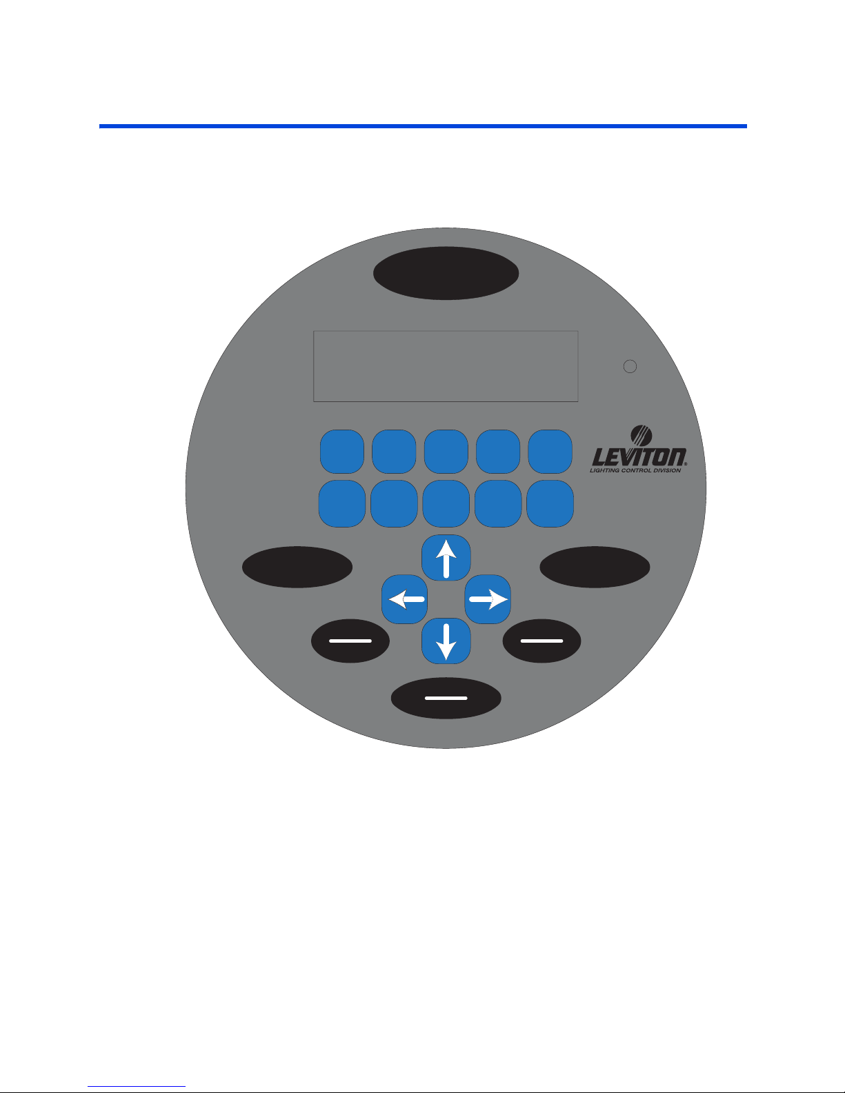
Operation
Operation LCD Display
This section discusses how your cabinet can be operated from the front panel, and
the actions that can be accessed from the front panel. The next sections on
configuration deal with the specific configuration and programming of your cabinet.
MENU
MON 12:28a E:OFF
L
STATUS: NORMAL
HYPHEN
1
MNO
67
RELAY LOCK
ABC
2
PQRS
DEF
3
TUV
GHI
4
WXYZ
89
SELECT
SAVE
JKL
5
SPACE
0
UNLOCKON/OFF
Z-MAX
TM
CANCELCLEAR
Figure 7: LCD Display
LCD Display
The LCD display helps you determine that the system is operating properly as well as
providing an easy and intuitive means of programming the panel.
When the system is operating normally the top line of the LCD display shows the
current day, time and the status of the event scheduler. The second line shows the
status of your relay cabinet, or in the case of EZ-Max, the status of the four relays in
the cabinet.
Z-Max Advanced Programming & Systems Design Guide rac00-sdg
Revision A:11/2005 Page 55
Page 66

Here is how you decipher the screen:
• Day and Time - The clock can display in either 12 or 24 hour mode.
• Daylight Savings settings for 12 Hour Clock
• Lower case "a" or "p" indicates that daylight savings is inactive
• Uppercase "A" or "P" indicates that daylight savings is active
• Daylight Savings settings for 24 Hour Clock
• Lower case "s" indicates that daylight savings is inactive
• Lower case "d" indicates that daylight savings is active
• Panel Lock Status
• "L" indicates that the panel is in a locked state
• "u" indicates that the panel is in a temporary un-locked state and will
automatically lock after 3 minutes of inactivity
• "U" indicates that the panel is in an un-locked state and will not automatically
enabled the lock
• Event Scheduler
• "E" will either show
• "OFF" Indicating that the event scheduler is turned off
• "---" indicates that no events have executed since the last system reset/
power cycle
• a number indicates the number of the last event executed
• Bottom Line - If an EZ-Max panel, shows the current status of the four relays in
your panel. Either On, or Off. An asterick (*) adjacent to any relay indicate that
particular relay is in an override state. The override could be either a timed override
or other front panel override. If the panel is not an EZ-Max panel, this bottom line
shows any relevant status messages.
Programming/Function Buttons
The several programming buttons are located around the display:
• MENU. Allows the user to navigate through the system
• SELECT/SAVE. Causes a new readout on the LCD display.
• CANCEL: Returns to the previous menu
• CLEAR. Clears the text or value that was just entered.
• RELAY ON/OFF: Button that allows a user to turn a relay ON or OFF, execute a
timed override, or execute a permanent relay override.
• LOCK/UNLOCK: Locks and Unlocks the user interface.
Many parameters can be modified using the LCD screen and a
password (setup code), however these modifications should be made
by a qualified factory technician.
Navigation Buttons
The lower center four buttons, used for navigation of menu items, are LEFT , UP
, DOWN , and RIGHT . Generally, the LEFT and RIGHT
buttons are used to navigate between ’fields’ on the screen, whereas the UP
and DOWN buttons generally change values in the fields.
Page 56
Page 67
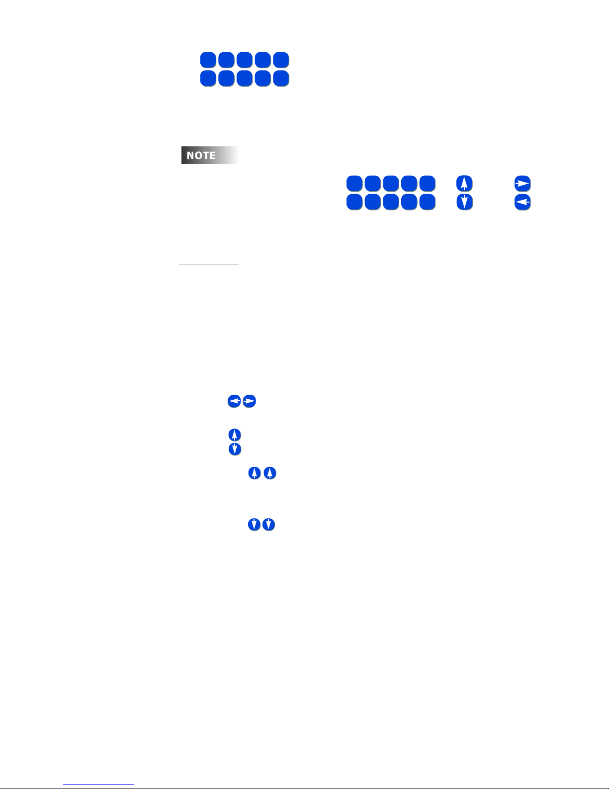
Operation Turning Relays On/Off from the front panel and front panel overrides
ABC3DEF4GHI
1-2
MNO7PQRS8TUV9WXYZ
The keys are used for alpha-numeric data entry.
6
In many circumstances where only use of the arrows keys are indicated, the number
keys work equally as well for data entry.
After approximately
3 minutes of
inactivity on any menu screen,
the LCD will revert back to the
status screen.
Auto-Repeat
In some screens where you are adjusting values, you may find it helpful to press and
hold an arrow key. After a brief moment, the key will repeatedly issue it’s command
giving you a quick way to scroll through a broad range of values.
JKL
SPACE
5
0
FOR FIELD VALUE CHANGES
{
ABC3DEF4GHI
1-2
MNO7PQRS8TUV9WXYZ
6
Figure 8: Arrow Key & Alpha-Numeric
JKL
5
SPACE
0
OR
FOR FIELD
NAVIGATION
AND
Key Functions
Turning Relays On/Off from the front
panel and front panel overrides
Pressing the Relay Button enters relay control mode. When in this mode, the
following keys can be used
• Use to adjust the relay number (number keys can also be used, but 2
digits are always required)
• Use to adjust the relay state, UP for ON, DOWN for off.
• Pressing (up arrow twice) puts the relay into an override ON state.
When in this state, no other relay panel function can alter the state of this relay
other than the front panel. (Only one arrow press is required if relay is already
on.)
• Pressing (down arrow twice) puts the relay into an override OFF state.
When in this state, no other relay panel function can alter the state of this relay
other than the front panel. (Only one arrow press is required if relay is already
on.)
• Pressing Select when in either override on or off mode will allow you to enter
a time and then activate Timed Override mode by pressing Select again. A
timed override forces the relay into the ON (or off) state for the elapsed period
of time. Once the time expires, the relay returns to the function indicated by
other controlling devices, or off if none are indicated.
To Turn a Relay On or Off
Step 1: Press Relay
Z-Max Advanced Programming & Systems Design Guide rac00-sdg
Revision A:11/2005 Page 57
Page 68
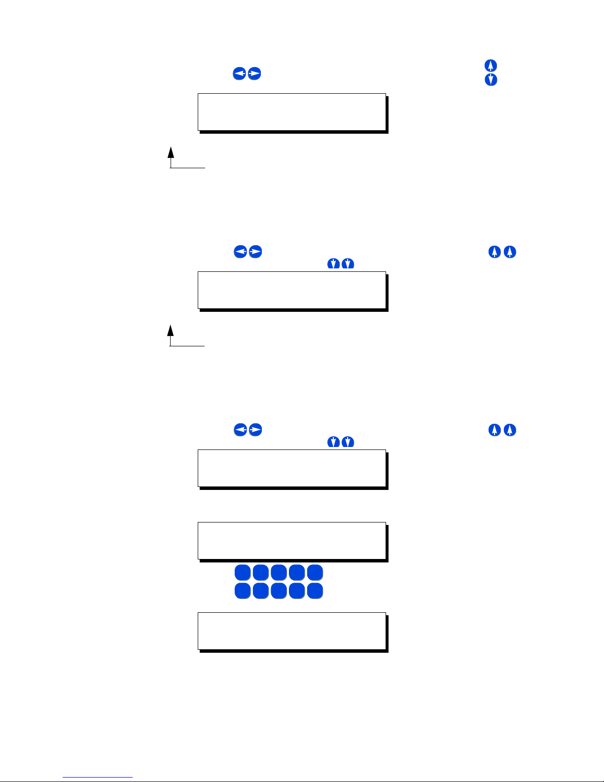
Step 2: Use to select the relay number you want to affect. Use to turn
the relay off or on
RLY: 01 ON
PRESS UP FOR
Step 3: Press Menu when complete to return to the main screen, or repeat Step
2
To Override a Relay On or Off
Step 1: Press Relay
Step 2: Use to select the relay number you want to affect. Use to
override the relay ON, or to override the relay OFF
RLY: 01 OVRDE ON
PRESS UP FOR
Step 3: Press Menu when complete to return to the main screen, or repeat Step
2
To Override a Relay On or Off for a specified time
Step 1: Press Relay
Step 2: Use to select the relay number you want to effect. Use to
override the relay ON, or to override the relay OFF
RLY: 01 OVRDE ON
PRESS UP FOR
Step 3: Press Select to access the override timer
RLY: 01 OVRDE ON
OVRD TIMER=00:00
Step 4: Use
ABC3DEF4GHI
1-2
MNO7PQRS8TUV9WXYZ
6
JKL
5
SPACE
0
RLY: 01 OVRDE ON
OVRD TIMER=00:15
Step 5: Pressing 0 0 1 5 would result in the above screen, entering an override
time of 15 minutes.
Step 6: Press Select a second time to set and start the timer
Page 58
Page 69

Operation Internal Relay Cabinet Controls
The insid
Step 7: Press Menu to return to the main screen, or repeat steps 2-6.
Internal Relay Cabinet Controls
In addition to front panel controls, your Z-MAX cabinets have two different types of
internal override switches for the relays:
• Master Override
• Relay Override
e of a relay cabinet, when energized,
can be DANGEROUS as HIGH VOLTAGES are
present. Fatal accidents are possible. Only trained
authorized personnel should have and gain access
to the internal workings of your relay panel,
access is not required for any normal
configuration or operational purpose.
Master Override
See the figure below for the location of the master override. The master override has
three modes of operation:
• Normal - Allows the Control Module and inputs to control the state of the relays
• All ON - Forces all of the relays to the ON state and the Control Module and
inputs can not turn the relays Off
• All OFF - Forces all of the relays to the OFF state and the Control Module and
inputs can not turn the relays On
Z-Max Advanced Programming & Systems Design Guide rac00-sdg
Revision A:11/2005 Page 59
Page 70
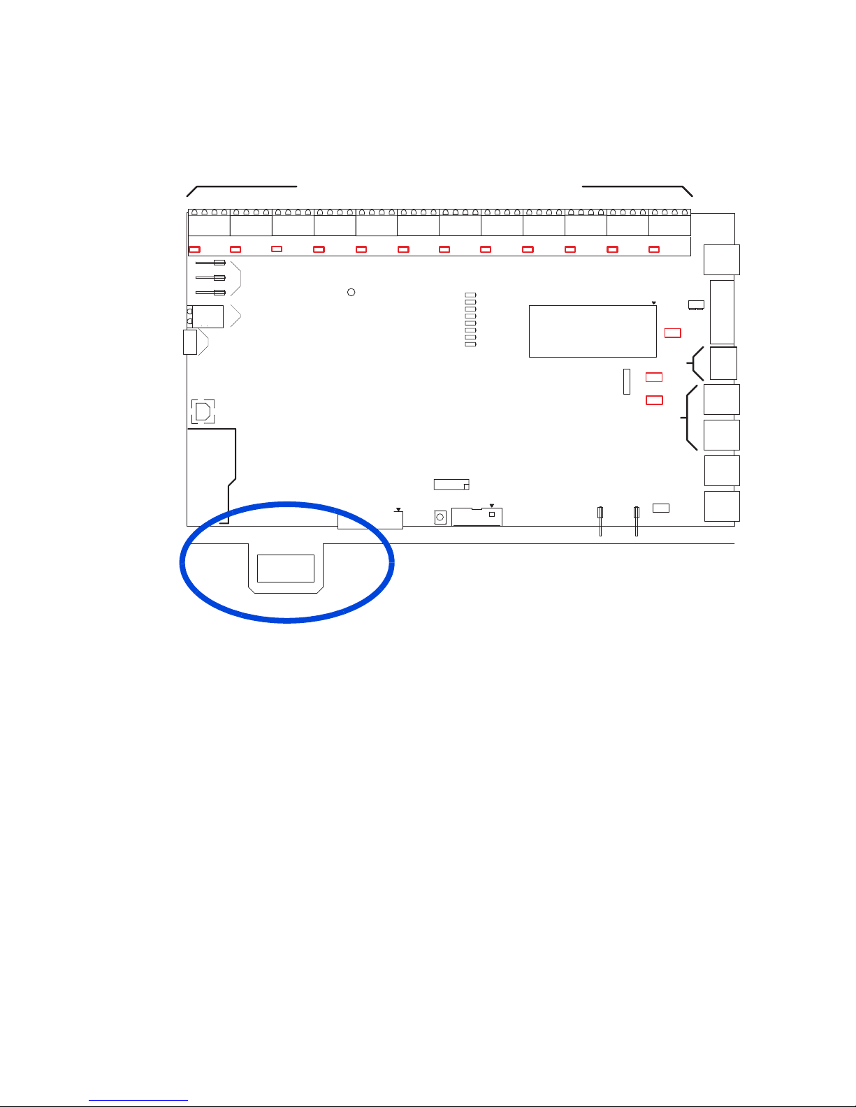
Switch Inputs and DMX ConnectorWire Range #14 - #24 AWG
Torque2 LB-IN
ANALOG/SWITCH INPUT/OUTPUTS TB 1-12*
Luma-Net Connector
Wire Range #12 - #24 AWG
Torque 5 LB-IN
IN
OUT
+24V
TB1
S1
NC
NO
COMMON
COM
EMERG
+24V
OUT
IN
COM
TB2
S2
EMERGENCY
EMERGENCY
INPUT - TB21 *
COM
RELAY
IN
COM
IN
OUT
+24V
OUT
+24V
TB3
TB4
S4
S3
SELECTOR S1 THRU S12
ALL RIGHTS RESERVED WORLDWIDE
SWITCH BOARD
(OPTIONAL)
J15
J6
USB TYPE B
SERVICE
ONLY
J7
RELAY BUS BOARD
ALL OFF NORMAL ALL ON
+24V
IN
OUT
COM
TB5
S5
ANALOG/SWITCH I/O*
C 2004 LEVITON MFG. CO.
COM
COM
IN
OUT
+24V
TB6
S6
RESET
OUT
IN
COM
IN
OUT
+24V
TB7
S7
JUMPER ON PULLS INPUT HIGH
}
JUMPER OFF IS DEFAULT
EMERGENCY
HEARTBEAT-C
LUMANET
DMX
CAN1
CAN2
ETH/MODEM
5V POWER
OX-70121-00-00-01 MASTER
OX-70121-00-00-02 SLAVE
KEYBOARD/LCD
J13
KEYBOARD/LCD
TB8
S8
(ALT)
J16
+24V
COM
IN
OUT
+24V
TB9
S9
ETHERNET MODULE
COM
MODEM MODULE
(OPTIONAL)
IN
OUT
+24V
TB10
S10
OR
AUX.
SERIAL
INPUT
COM
IN
COM
TX
RX
MASTER/SLAVE
AC2
18 VAC IN
OUT
IN
COM
+24V
TB11
S11
ETHERNET/MODEM
LUMA-NET TB13**
JP36
TB17
1
JP7
JP9 TERM
AC1
JP11
TERM
COM
OUT
+24V
TB12
S12
VOLTAGE INPUT
123
SELECT
+12V
+24V
JP6
TERM
DMX 512
TB 14**
TERM
JP30
REM+
REMCOM
+V
TERM
LOCK
COM
DD+
TB20
TB15
TB19
TB16
1
1
1
1
1
Figure 8: Location of Master Override Switches for Large and Small Control
Modules
Individual Relay Overrides
Each relay has an individual override switch. See the Figures below for the location of
these switches in each cabinet.
Page 60
Page 71
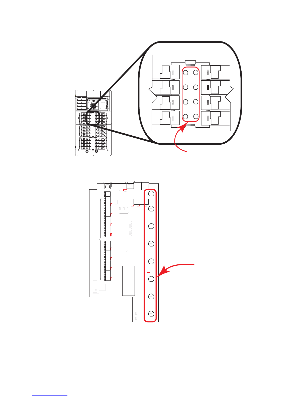
Operation Individual Relay Overrides
Individual Relay
Override Switch
Figure 9: Location of Individual Relay Override Switches in 24 and 48
cabinets
LUMA-NET
USB
TB9**
+V
R+
R-
TB9
JP13
TB17
BYPASS
SWITCH
COM
TB1
+24V
OUT
S1
IN
COM
TB2
+24V
OUT
S2
IN
COM
TB3
+24V
OUT
S3
IN
COM
TB4
+24V
OUT
S4
IN
COM
TB5
+24V
OUT
S5
IN
COM
TB6
+24V
OUT
S6
IN
COM
TB7
+24V
OUT
S7
IN
COM
TB8
+24V
OUT
S8
IN
SERVICE ONLY
COM
LUMA-NET
TERM
ON
NORMAL
OFF
S14
COM1
EMERGENCY
RELAY
JUMPER OFF IS DEFAULT
JUMPER ON PULLS INPUT HIGH
}
ANALOG/SWITCH I/O*
SELECTOR S1 THRU S8
ETHERNET/MODEM
1
JP9
J3
EMERGENCY - TB17*
COM.
EMERG.
Switch
Inputs
LCD
INTERFACE
J1
Luma-Net Connector
Wire Range #12 - #24 AWG
Torque 5 LB-IN
Switch Inputs and DMX ConnectorWire Range #14 - #24 AWG
Torque2 LB-IN
MASTER/
DMX 512
SLAVE
TB10*
TRM
LCK
TB11
D-
D+
TB10
TB15
JP15
JP21
CAN 1
DMX
TERM
TERM
EMERGENCY
HEARTBEAT-C
LUMANET
ETH/MODEM
5V POWER
HEARTBEAT-R
TB13
11
RELAY 1
TB16
1 1
JP35
CAN 2
TERM
RELAY 2
RELAY 3
RELAY 4
RELAY 5
S1
RELAY 6
COM
31
+24V
+12V
LUMA-NET
VOLTAGE
SELECT
NO1
NC1
D2
D4
D6D7DMX
D3 CAN1
D8 CAN2
D1
D12
D27
LEVITON ASSEMBLY
OX-70129-00-00-01 NETWORK
OX-70129-00-00-02 BASIC
C 2004 LEVITON MFG. CO.
ALL RIGHTS RESREVED WORLDWIDE
JP41
ETHERNET
MODULE
OR
MODEM
MODULE
(OPTIONAL)
RELAY 7
18 VAC IN
AC1
AC2
RELAY 8
RESET
Individual Relay
Override Switches
Figure 10: Location of Individual Relay Override Switches in the 8 Cabinet
These switches have one primary use with two modes of operation:
Z-Max Advanced Programming & Systems Design Guide rac00-sdg
Revision A:11/2005 Page 61
Page 72

• Local override of individual relay without having to go through the Control Module
• Temporary - Any control input with a higher priority can change its state
• Locked Out - Event scheduler and control inputs, regardless of Priority will not
be able to alter its state
To temporarily change a relays state using its override Switch:
Step 1: Open the cabinet door using the supplied key
Step 2: Press the switch next to the relay you wish to change
The relay will audibly click when it changes states (ON to OFF and vice
versa)
There is a green LED above each relay override switch. If the LED is
on, the relay is ON. If the LED is OFF, the relay is OFF.
Step 3: Press the switch again to turn the relay on and off.
Pressing the individual relay override switch will always clear higher
priority overrides for the relay. This allows manual control of the relay
even when Emergency or Master Override is active
To lock out a relay using its override switch:
Step 1: Open the cabinet door using the supplied key
Step 2: Get the relay to the state that you want to Lock it in. For example, if you
wish to lock the relay in the On state and it is Off, press the switch one
time to toggle the relay to the On state.
Step 3: Press and hold the Switch for approximately 5 seconds until the LED
beneath the switch begins to blink.
The relay will audibly click when it changes states (ON to OFF and vice
versa)
There is a green LED above each relay override switch. If the LED is
mostly on when it blinks, the relay is locked ON. If the LED is mostly
OFF when it blinks, the relay is locked OFF.
To unlock a relay using its override switch:
Step 1: Open the cabinet door using the supplied key
Step 2: Press and release the switch of the relay that is locked out
The relay will change its state from On to Off or vice versa
Page 62
Page 73
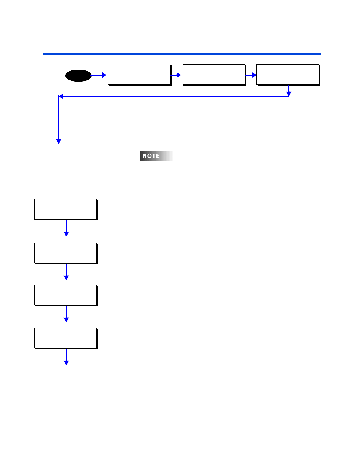
Ethernet Module
Alth
thi
Ethernet Module
MENU
PHONE/ETHERNET
MODE: ETHERNET
ETHERNET
DHCP: ENABLED
MAIN MENU SELECT
CONFIGURATION
Z-Max relay panels can be configured to participate on an TCP/IP Ethernet network.
From the ethernet network you can operate your panel from the command line
interface (CLIF) or you can transfer data to/from various applications.
ethernet setup and configuration. The mode
module configuration is covered in a previous
chapter.
CONFIGURATION
SYSTEM SETUP
ough
entitled phone/ethernet, this section only covers
s part of the menu structure is
SYSTEM SETUP
PHONE/ETHERNET
Operation Mode
The ethernet card has two operation modes:
•
Ethernet
•
None
should be disabled
- The ethernet module is installed
- indicates that no module is installed or both modem and ethernet access
DHCP
On networks which support DHCP for IP address allocation, your ethernet card can be
configured to retrieve it’s address from a DHCP server. If you have a DHCP server on
your network, this option should be enabled.
IP Address
ETHERNET IP ADDR
192.168.001.002
If DHCP is disabled, you will be asked for an IP address. Please enter a unique IP
address when requested.
Subnet Mask
ETHERNET IP MASK
255.255.255.0
Z-Max Advanced Programming & Systems Design Guide rac00-sdg
Revision A:11/2005 Page 63
If DHCP is disabled, you will be asked for an subnet mask. Please enter the
appropriate mask when requested.
Page 74

Page 64
Page 75
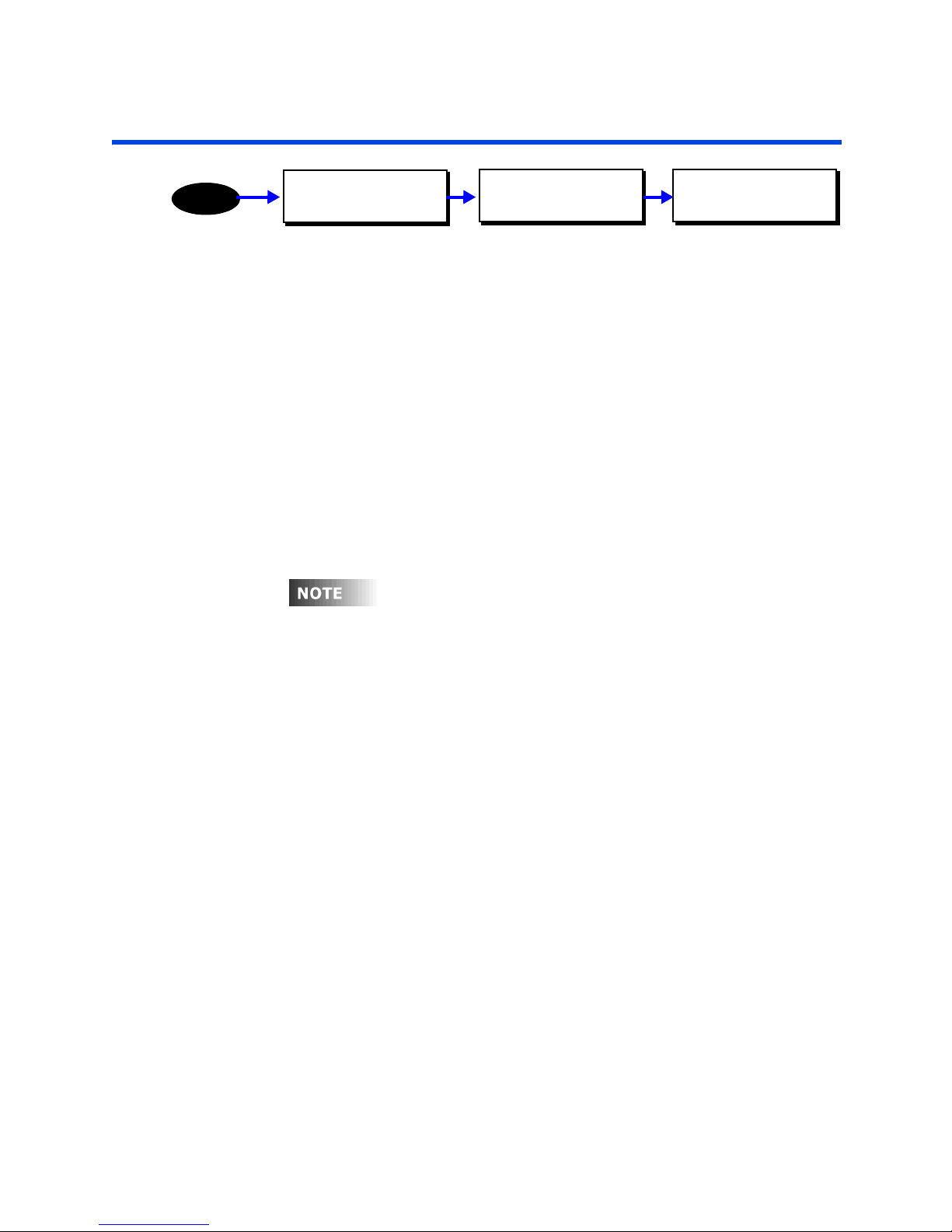
Priorities
Priorities
MENU
MAIN MENU SELECT
CONFIGURATION
There are many control signals and events all coming into the relay cabinet at the
same time. Priority levels are used to distinguish which event actually occurs when
competing commands are sent.
For example, consider the situation where you want the scheduler to turn the lights
on in a lobby at 7:30am and off at 5:30pm so that the lights are on during business
hours. Also consider for a moment that there is a switch in the lobby which can be
used to turn on/off the lobby lights. Now, consider that the scheduler turns the lights
on at 7:30am but Joe the janitor comes in and presses the switch to turn off the lights
at 7:45am. The lights could remain off all day long! To resolve this problem, priorities
can be used.
Your Z-MAX relay cabinet has (16) priority levels which can be assigned to control
signals and events. 1 is considered to be the highest priority, 16 is considered to be
the lowest priority.
Your Z-MAX relay panel presents a warning when you change the
priority level. This warning is present because simply changing the
priority level of a control signal can drastically change how your panel
operates. Make sure you understand what you’re doing and have a
good reason for doing it. If not….you probably should leave them
alone.
CONFIGURATION
SYSTEM SETUP
SYSTEM SETUP
PRIORITIES
Each relay has a defined state at each priority level:
•
ON
- indicates that the relay should be on at the specified priority level and any
lower priority commands should be ignored
•
OFF -
indicates that the relay should be off at the specified priority level and any
lower priority commands should be ignored
•
RELINQUISH
a lower priority level
When a relay determines what state it should be in, it steps through each priority
level and looks for any controlling commands. When it finds one it executes it. If the
command is relinquish, it proceeds to the next priority level. If it steps through all 16
priority levels and finds no on or off commands, then the relay is turned off.
When a signal or event is executed at a priority level, no lower priorities will have any
effect on that relay until control at the higher priority level is relinquished. The control
signal or event will continue to be updated at the lower priority, it just will have no
effect on the relay.
- indicates that control at the specified priority level is relinquished to
Z-Max Advanced Programming & Systems Design Guide rac00-sdg
Revision A:11/2005 Page 65
Page 76
DMX can be somewhat of an exception to the priority rules in that it
has a special configuration option called “Force”. When DMX is in
“Force” mode, DMX will automatically take control over all other
control signals at the same priority level anytime a DMX signal is
present.
The factory default for priority levels is as follows:
Control Signal Designation Priority Level
Internal Bypass switch BYPASS 1
Emergency Input EMERGENCY 2
Internal override switch override
commands
Internal override switch on/off
commands
Front Panel Overrides KBD OVERRIDE 4
Front Panel Control KBD NORMAL 8
Luma-Net Input Luma-Net 8
DMX Input DMX-512 8
Photocells PHOTOCELLS 7
Occupancy Sensor inputs OCC SENSORS 8
Low voltage switch inputs LV SWITHCES 8
Relays activated by the power
restore feature
Scheduled Events SCHEDULER 8
TIM Normal Commands TIM NORM CMDS 8
TIM High Priority Commands TIM HIGH CMDS 7
SWT OVERRIDE 3
SWT NORMAL 8
POWER RESTORE 8
Page 66
Default Priorities should only be changed with full and complete
understanding of the implications of your change and the priority
system. Incorrect settings can cause relays to function incorrectly. In
the event that a high-priority actions is required, Leviton recommends
always using actions to which any execution priority level can be
assigned.
Page 77
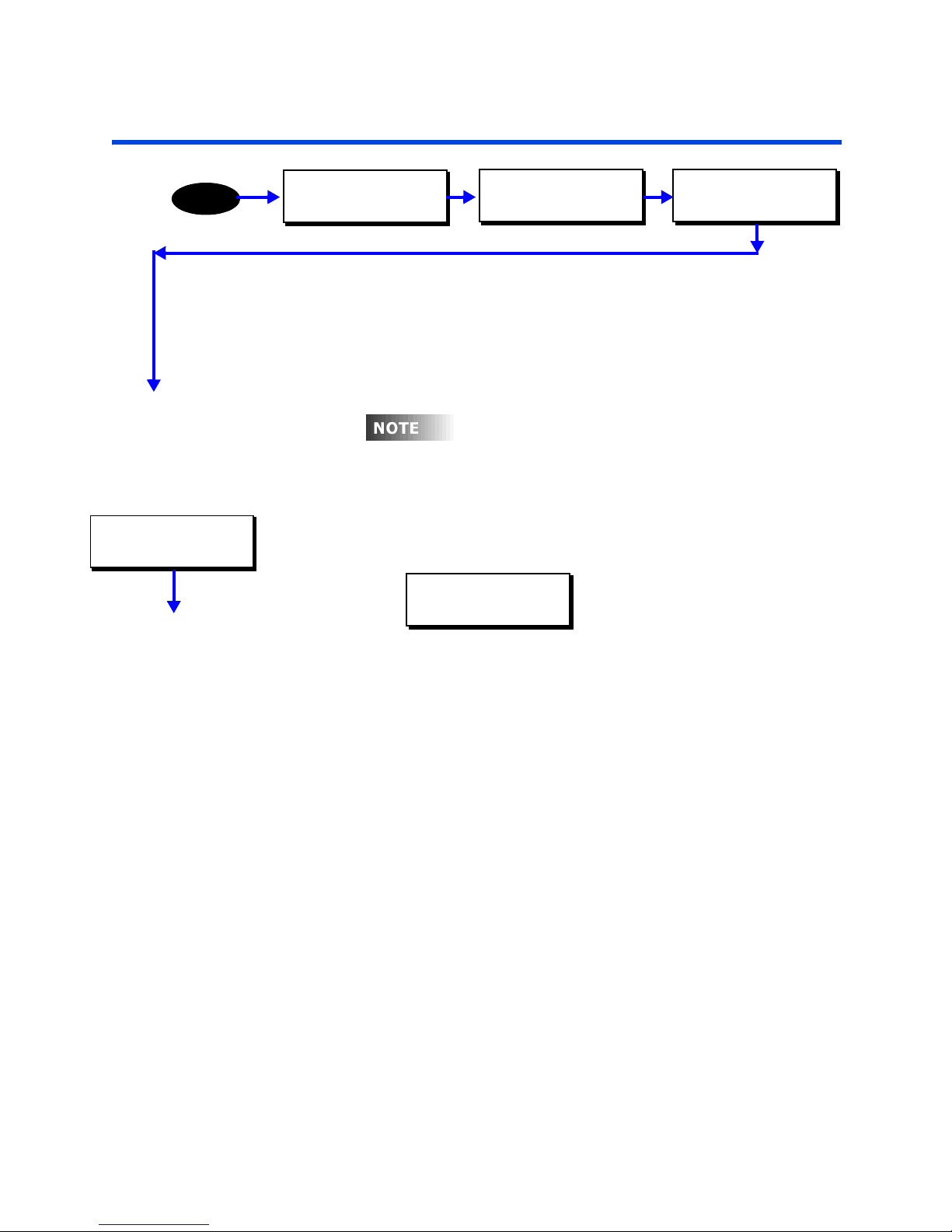
Passwords
Y
ith
Passwords
MENU
CONFIG PASSWORDS
ADD PASSWORD
MAIN MENU SELECT
CONFIGURATION
Your Z-Max relay panel has security features built in which are used to secure access
to the panel when accessing from any external network and can be used to secure
local access to the panel. Security is controlled by a password which has defined
access privileges associated with it.
password can not be deleted but can be modified.
CONFIGURATION
SYSTEM SETUP
our relay panel ships as default w
administrative level password of 1234. This
SYSTEM SETUP
CONFIG PASSWORDS
an
Adding Passwords (Access Codes)
Up to 256 passwords can be entered into the system. To add a password, select the
ADD PASSWORD option from the password configuration menu.
ADD:002 PW:0000
GP:0000 ADMIN
Each password has several settings:
• The "ADD" field is purely information and indicates the number of the added
password
• The "Pw" field is the password itself
• The "Gp" field is the group number which can be accessed by this password. Access
to all groups is granted if the password mode is ADMIN regardless of this setting. If
the password type is USER and the Gp field is 0000, no control will be granted as
user access codes can only control a single group.
• The bottom right most field is the MODE field. Mode can be any one of the
following:
• ADMIN - When entered, the user is granted access to all administrative
functions of this relay panel
• INSTALL - This password grants "installation" level access to the relay panel
• TECH - This mode grants "technician" level access to the relay panel
• USER - grants user level access to the relay panel
• The modes above grant access to the panel mainly from the front panel. The
possible modes as listed below are command level passwords which allow for the
specific command to be issued to the specified group from the touch tone interface.
When password is entered, the command is executed and the call is then
disconnected.
• OFF - turns off the associated group
• ON - turns on the associated group
Z-Max Advanced Programming & Systems Design Guide rac00-sdg
Revision A:11/2005 Page 67
Page 78
CONFIG PASSWORDS
EDIT PASSWORD
CONFIG PASSWORDS
DEL PASSWORD
• TON - turns on the associated group for a cabinet specified override time
• BWO - initiates a blink warn for the associated group
• BWC - cancels an in-progress blink warn for the associated group
• OVRDON - turns on the group at the "higher" priority level as specified in the
priority system setup option
• OVRDOFF - turn off the group at the "higher" priority level as specified in the
priority system setup option
• OVRDREL - relinquishes control of the relay at the "higher" priority level to all
lower priority levels
Editing Passwords
Editing is mostly the same process as adding passwords excepting the fact that you
first much choose which password you want to edit, then perform your editing
activities and then save your changes.
Deleting Passwords
Passwords can be deleted by choosing this menu option. You first select the password
to delete, and then confirm or deny the deletion. If the deletion is confirmed, the
password is permanently removed from the database.
Page 68
Page 79
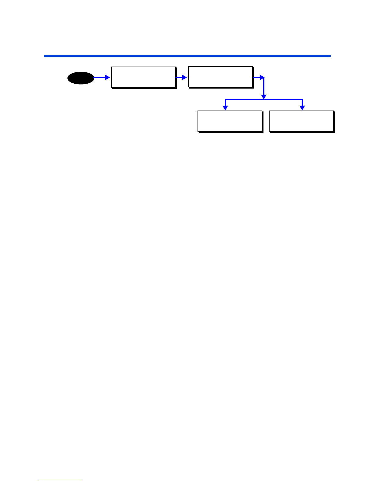
Switch/Discrete Inputs
Switch/Discrete Inputs
MENU
MAIN MENU SELECT
CONFIGURATION
The inputs section of the configuration menus allows you to configure all of the local
and remote switch inputs to your relay cabinet. Configuring any switch input is a twostep process:
Step 1: Define the type of switch input
Step 2: Assign actions and behaviors to that input
The define types menu is where you define the type of device or function of the input,
and the assign actions menu is where you define what happens when an input signal
(or lack thereof) is received at the particular input.
The system accepts the following switch Input types:
• Low Voltage Switches
• Momentary
• Preset ON
• Preset OFF
• Maintained
• Momentary Timed
• Momentary On/Off
• Digital Switches
• Occupancy Sensors
• Photocells
• Contact Closure Inputs
• Remote Inputs from a master/remote network connected panel
CONFIGURATION
INPUTS
DISCRETE INPUTS
DEFINE TYPES
DISCRETE INPUTS
ASSIGN ACTIONS
Switch Numbering
There are a maximum of 240 definable switch inputs in the programming structure.
These inputs are allocated first to any local inputs, second to any remote inputs from
master/remote connected panels, and lastly to network switches.
The first available input for a digital switch can be calculated as 1+[number of local
relays]+[number of remote relays]. For example, if in the global defaults you had
defined 24 local relays and 48 remote relays, then your relay number would be as
follows:
• 1-24 local inputs
Z-Max Advanced Programming & Systems Design Guide rac00-sdg
Revision A:11/2005 Page 69
Page 80
DISCRETE INPUTS
DEFINE TYPES
• 25-72 reserved for remote relays
• 73-240 reserved for network/digital switch inputs
Define Switch Types
The system programming is defaulted for all input types to be set up as Switches and
their behavior as Active High. If you do not have any other type of input or behavior
type, then you can skip this section.
To define the type of switch input
Step 1: Once "Define Types" has been selected from the menus, press or
enter a number from the keypad until you get to the desired input
number or type in the three digit number from the keypad.
Step 2: Press Select/Save
Step 3: Press until you reach the desired switch type. The following are the
choices:
• SWT = Switch
• PHO = Photocell
• OCC = Occupancy Sensor
• CC = Contact Closure
• --- = nothing connected
Step 4: Press . once to position the cursor in the next field
Step 5: Press the or to toggle the input behavior field to the desired
value. See the following list for the available behavior types:
• SWT = Switch
• Act HIGH - Active High (All Leviton Low Voltage Switches and Z-MAX
Digital Switches)
• Act LOW - Active Low
• PHO = Photocell
• Fc:1-999
• OCC = Occupancy Sensor
• Act HIGH - Active High
• Act LOW - Active Low
• CC = Contact Closure
• Act HIGH - Active High
• Act LOW - Active Low
Step 6: Press Select/Save and the following menu will appear whenever an input
type is changed. Relays and parameters previously assigned to that
input will be deleted:
Page 70
CHANGE FORMAT? N
Data Kept As Is!
Page 81
DISCRETE INPUTS
ASSIGN ACTIONS
Switch/Discrete Inputs Assign Actions to Inputs
Step 7: Press to toggle the N to a Y.
Step 8: Press Select/Save
Step 9: Repeat Steps as necessary for all switch inputs.
Assign Actions to Inputs
Once you have defined the Switch type, you must associate an action to that switch.
An action consists of two parts, a behavior which dictates how the switch input
interacts with the relay cabinet, and second, you must assign relays and/or groups to
reach to the input.
When assigning actions, a different menu structure is employed for each of the
following previously defined input types:
• Switch Inputs
• Photocells
• Occupancy Inputs
• Contact Closures
The general procedure for assigning actions to inputs is as follows:
Step 1: Select Assign Actions from the inputs configuration menu
Step 2: Select the type of input you wish to configure
ASSIGN ACTIONS
SWITCH INPUTS
Possible input types are as follows:
• Switch Inputs
• Photocell Levels
• Occupancy Inputs
• Contact Closures
Step 3: Select the input number you wish to configure
ASSIGN SWITCHES
001:LOCAL
Note: Only the input numbers for the input which are defined as the
selected type will show. If for example you are trying to configure an
occupancy sensor connected to input #3 yet input #3 doesn’t show in
the list, it’s input type is probably incorrectly defined. Please see the
"Define Types" section earlier in this chapter.
Step 4: Select the behavior of this input
Z-Max Advanced Programming & Systems Design Guide rac00-sdg
Revision A:11/2005 Page 71
SWITCH:001 LOCAL
Momentary
Switch input behavior only is shown - all behaviors for each type are
discussed below
Page 82
Step 5: Assign the relays to this input. Typically, there are several menu items
associated with this process: ADD, EDIT, DELETE, & EXIT. This menus
items are implemented in the next section.
Step 6: Save your changes and proceed to other configuration tasks.
Relay assignment to inputs
The process of assigning relays to inputs is the same regardless of the type of input
selected. This section details the process by which relays are assigned to an input.
ADD RELAY/GROUP:
This selection allows a relay, relay range or group number to be added to the input’s
control.
Step 1: Press or to select relay or group.
Step 2: If relay is selected, press to move to the first relay number field.
Step 3: Use and to select the relay number.
SWITCH:006 LOCAL
Add 1:RLY 01-01
Step 4: Press to move to the second relay numeric field.
Step 5: Use and to select the second relay number. This number
cannot be larger than the first relay number. If only the first relay
number is desired, make the second number the same as the first. If a
range is desired, make the second relay number the last number of the
range.
Step 6: If group is selected, press to move to the group number field.
Step 7: Use and to select the group number desired.
Step 8: Once the relay/group number(s) have been entered, press Select/Save.
EDIT RELAY/GROUP:
This menu allows previously programed Relay/Group items to be edited.
From the end of the previous Step:
Page 72
SWITCH:006 LOCAL
Add 2:GRP 1
The menu will be returned to the point where more relay/group
management can be initiated.
Up to 32 relay/group entries can be assigned to each input.
Page 83
Switch/Discrete Inputs Assign Actions to Inputs
Step 1: Press or to select desired relay/group entry to edit.
SWITCH:006 LOCAL
EDIT RELAY/GROUP
Step 2: Press Select/Save to begin editing.
Step 3: Press or to change between relay or group if desired.
Step 4: Press to move to the number field to make appropriate changes
using and .
Step 5: Press Select/Save to save the changes.
DEL RELAY/GROUP:
This menu allows previously programed Relay/Group items to be deleted.
From the end of the previous step:
Step 1: Press or to select desired relay/group entry to delete.
SWITCH:006 LOCAL
DEL RELAY/GROUP
Step 2: Press Select/Save to initiate the deletion.
Step 3: The LCD will prompt for confirmation.
DELETE Y/N? Y
Del 1:RLY 01-01
Step 4: Press to change the default "N", for No, to "Y’, for Yes.
Step 5: Press Select/Save to delete the item.
EXIT (DONE):
This item will move back up to ASSIGN ACTIONS menu.
Switch Inputs
There are six behaviors that can be assigned to a switch input:
• Momentary
• Maintained
• Preset On
• Preset Off
Z-Max Advanced Programming & Systems Design Guide rac00-sdg
Revision A:11/2005 Page 73
Page 84

• Momentary Timed
• Momentary On/Off
Momentary
: This behavior assigns a toggle (push On/push Off) function to the input.
Only active states are recognized. Upon a new active state, the input will either turn
on or turn off the relays assigned based on their current state.
Momentary Timed
: this behavior will allow you to turn "on" the assigned relays for an
amount of time specified in the global defaults Tswit setting
Momentary On/Off
: This unique input type is used with any momentary on/off (2
pole) center off switch with or without LED feedback. When using this switch input
behavior, the input expects to receive approximately +24vdc at the switch input to
signal an "ON" state and approximately +12vdc at the switch input to signal an "OFF"
state. For this input type, the use of rac00-2sb or rac00-2sc switch input adapters are
required, or, the use of an LV240-00W entrance station.
Maintained
: Under this behavior, the assigned relays will be on whenever the input
detects an active (on) state. The assigned relays will be off whenever the input
detects an inactive (off) state.
Preset On
: Presets can only operate with a momentary switch. The advantage of a
preset input is that it is included in a preset association. This allows multiple switch
inputs assigned to the same association to interact together, allowing only one to be
on at a time.
EXAMPLE
For example, if three inputs are configured as Preset On, with the
inputs assigned relays 1, 2 & 3 respectively, only one relay can be
on at a time. If Switch 1 is activated, relay 1 turns on. If Switch 2 is
then activated, relay 2 turns on and relay 1 turns off along with
switch 1 input.
Preset Off:
When a switch input has a Preset Off behavior, it will turn off all relays that
are assigned to switches configured as Preset On providing they are in the same
preset association.
Remember that Preset On and Preset off have Preset Associations.
This allows you to associate switch inputs with different preset
associations (groups). Thus you can have several switches that utilize
the Preset function but do not affect other switches. A good example
of this is a 2 button switch where button 1 is for turning lights on and
button 2 is for turning lights off.
Digital Switches
Digital Switches are an extension of low voltage switches in that a digital switch is
assigned to a "virtual" discrete input which is then programmed identically to a local
Page 74
Page 85
Switch/Discrete Inputs Assign Actions to Inputs
discrete input. The only difference is the way they are wired to the system and how
they are networked over Luma-Net. Set up is very similar in philosophy.
For information about inputs which are available for use as a digital switch input, See
“Switch Numbering” on page 69.
To set up a digital switch:
Step 1: Press the Menu Button
Step 2: Press until you get to the Configuration Screen
Step 3: Press Select/Save
Step 4: Press until you get to the Discrete Inputs Screen
Step 5: Press Select /Save
Step 6: Press until you get to the Define Types Screen
Step 7: Press Select /Save
Step 8: Press until the flashing field reads 49 or greater (this depends on
which switch you are trying to set up)
You can also type in the 3 digit number of the switch. Therefore if
you are trying to set up 49, type 049 from the keypad.
Step 9: Press Select/Save
Step 10: The Cursor will jump to the type field and if still at factory default
values, will be flashing SWT as Shown:
SET INPUT TYPES
049:SWT Act HIGH
Step 11: Press until SWT is in the field
Step 12: Press . once to position the cursor in the next field
Step 13: Press until Act HIGH is in the field
Step 14: Press Select/Save to store the settings and move you to the next
screen
SET NETWORK: ecl
ADD: X BT: X
Step 15: Press. once to position the cursor in the field marked ADD. This is
the Luma-Net network address of the digital switch you are
programming.
Step 16: Press until you get to the desired network address
Step 17: Press . once to position the cursor in the field marked BT. This
refers to the physical button number on the station itself.
Step 18: Press until you get to the desired button
Step 19: Press Select/Save
Z-Max Advanced Programming & Systems Design Guide rac00-sdg
Revision A:11/2005 Page 75
Page 86
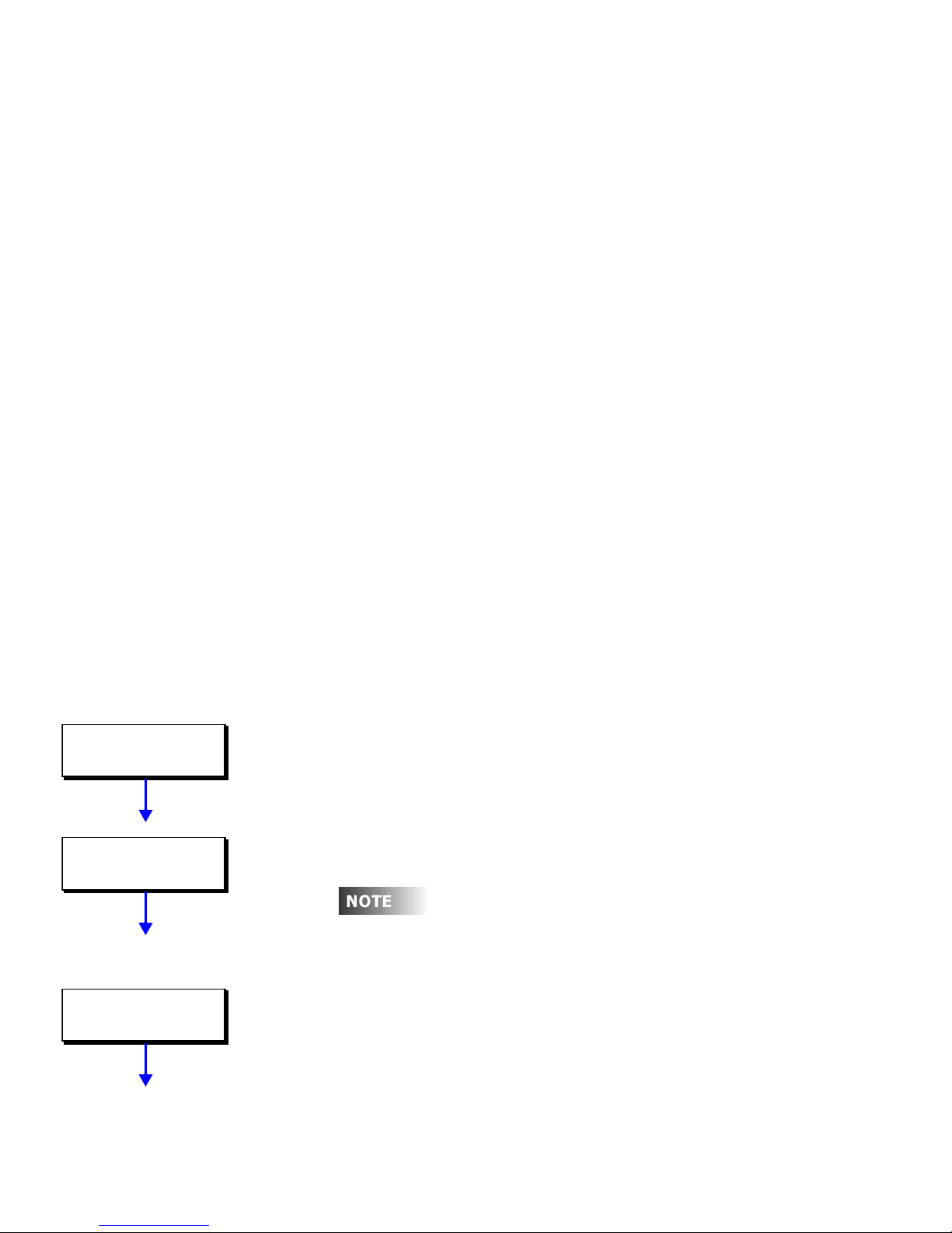
Step 20: Repeat Steps 8 - 19 as necessary for every button on every station you
If th
are programming.
Step 21: Assign actions just as for a local switch.
Occupancy Inputs
The process for setting up Occupancy Sensors as inputs to your Z-Max relay cabinet is
identical to low voltage switches except that the type should be defined as OCC.
When assigning actions to occupancy inputs, the following three behaviors can be
assigned to the input:
• NORM ON - AUTO OFF: When the occupancy sensor detects movement and goes
active, relays assigned to this input will turn on only if all relays have been off for
more than the Re-trigger Delay time (set later). Relays will turn off when the
occupancy sensor goes inactive after the Off Delay time (set later). This scenario is
used to hold off reactivating the relays by the sensor when one or more lights has
been manually turned off to temporarily adjust the lighting levels in the room.
• ALWA ON - AUTO OFF: When the occupancy sensor detects movement and goes
active, relays assigned to this input will turn on. Relays will turn off when the
occupancy sensor goes inactive after the Off Delay time (set later).
• MAN ON - AUTO OFF: If the input is set to this behavior, the occupancy sensor has
no effect on the relays when it goes active. Instead, the relays must be turned on
via any other means (typically a switch input). When the occupancy switch goes
inactive it will turn off the relays. This application is good for when manual control
is desired from a switch but you want the lights to turn off when someone forgets
to turn them off. This functional operation is required by California Title 24 in most
applications.
OccSen: 3 LOCAL
BLINK WARN: YES
OccSen: 3 LOCAL
BLINK WARN: YES
OccSen: 3 LOCAL
RTG DELAY:000sec
Additionally, when setting up occupancy inputs, several additional questions are
asked:
Blink Warn
Indicates whether or not a blink warn should be issued before turning off the lights
associated with this occupancy sensors.
Delay from vacancy until lights off
Allows you to set a delay between when the occupancy sensor indicates that the room
has become vacant and the lights turn off.
e occupancy sensor used already has an
internal delay, the off delay time will be added to
the sensor delay. When using sensors with
internal delay, set delay to 0 (default)
Re-trigger Delay
Allows you to set a mandatory delay between when the lights are turned off (by
occupancy sensor or other method) and the earliest point at which the lights can be
turned on, regardless of occupancy state.
Page 76
Page 87

OccSen: 3 LOCAL
ADD RELAY/GROUP
Switch/Discrete Inputs Assign Actions to Inputs
Relay Assignment
Assign relays and groups to this input just as for other input types.
Contact Closures
Contact closures are switch inputs which instead of having relays or groups assigned
to them, instead have actions assigned to them. Contact closures have two possible
behaviors:
Maintained
: Under this behavior, two actions can be assigned. The first action, Action
1, occurs whenever the input detects an active (on) state. The second action, Action
2, occurs whenever the input detects an inactive (off) state.
Alt Action:
This behavior assigns a toggle function to the input. Only active states are
recognized. Upon a new active state, the input will issue Action 1 if Action 2 was
issued last or Action 2 if Action 1 was issued last.
Z-Max Advanced Programming & Systems Design Guide rac00-sdg
Revision A:11/2005 Page 77
Page 88
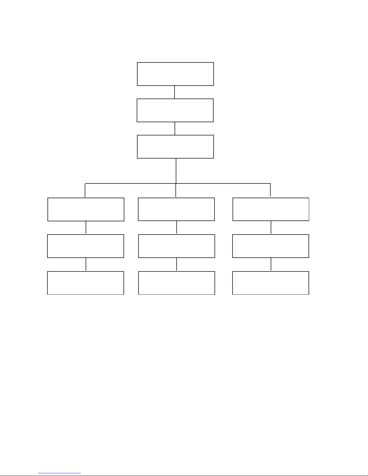
Photocell and Photocell Levels
ASSIGN ACTIONS:
PHOTOCELL LEVELS
ASSIGN PHOTOCELL
002:LOCAL
PHOCEL:002 LOCAL
ENABLED: YES
PHOCEL:002 LOCAL
1.REL ON-FOR OFF
PHOCEL:002 LOCAL
DELAY:004min
PHO:002 TRIG:01
ON:NA OFF:NA Fc
Photocells have a variety of uses and applications but most can be broken down into
two categories: simple on/off control and the more complex daylight harvesting. Your
Z-MAX cabinet is capable of doing both. To connect photocells to your relay cabinet,
please see the installation chapter which addresses the installation of a photocell with
the cabinet. This section will walk you only through the configuration aspects of
photocell operation. Additionally, you may find it helpful to review the sidebar
information on this page which addresses both background information on photocell
operation and daylight harvesting. Configuration of your Z-MAX cabinet for use with
photocells assumes that you’re already comfortable with both topics.
PHOCEL:002 LOCAL
2.FOR ON-FOR OFF
PHOCEL:002 LOCAL
DELAY:004min
PHO:002 TRIG:01
ON:NA OFF:NA Fc
PHOCEL:002 LOCAL
3.FOR ON-REL OFF
PHOCEL:002 LOCAL
DELAY:004min
PHO:002 TRIG:01
ON:NA OFF:NA Fc
Photocells operate in one of three modes, these modes define the characteristics of
how photocell operation interacts with the relay panel. It’s crucial to understand the
three modes prior to commencing programming to ensure that the desired result is
achieved. The three modes are as follows:
• Relinquish / Force Off
• Force On / Force Off
• Force On / Relinquish
Page 78
Page 89

Switch/Discrete Inputs Assign Actions to Inputs
The modes express what happens to the assigned relays/groups at the "ON" trigger
point followed by what happens at the "OFF" trigger point. The On trigger point
occurs as the foot candle levels from the photocell drops and the Off trigger point
occurs when the foot candle level from the photocell is rising. Another way to think
about the modes is that the first part of the mode indicates what action will happen
when the "sun" is rising or getting brighter and the second portion of the mode
indicates what will occur when the "sun" is setting or getting darker outside.
Mode 1, Relinquish On/ Force Off,
applications where you want to turn relays on
manually and off automatically when it gets bright.
This mode also allows manual control to turn relays off
and on. This is the typical daylight harvesting
application. For example, think about a classroom
where there is only an on/off switch for use by the
occupants. The teacher comes in the morning, when
it’s dark outside, and turns on the switch. All of the
lights come on. When the sun comes up and natural
light fills the space, the photocell would detect lights
which would pass the trigger point and then turn off
some or all of the lights in the room. When the sun
goes down or prolonged cloud cover exists making the
room dark again, the photocell would detect the
darkness and then turn the associated relays on and
then relinquish
control back to the manual switch
which if in the on position would turn the lights on.
Since up to (16) trigger points for the same photocell
is useful for
Daylight Harvesting
In a daylight harvesting
application, the goal is to
maintain a consistent
lighting level within the
space, regardless of the
source of light which could
be either daylight or
dimmable artificial light. If
this lighting level can be
maintained completely with
daylight, no artificial light is
necessary. However, if the
day lighting is not sufficient
to meet the desired level, it
can be boosted by the
artificial light connected to
your relay cabinets
can be programmed, this can be used with multiple
zones of relays to allow different levels of ambient light in the room, or rather multizone control.
Mode 2, Force On / Force Off
, is useful for applications where you do not want to
to allow manual control of the lights at all. The relays come on when it’s dark, and go
off when it’s bright. Think about parking lot lighting, when it’s dark the lights go on,
when it’s light the lights go off and you don’t ever want anything else to override it.
Mode 3, Force On / Relinquish OFF
when it gets dark and then allows for manual control when it gets bright. A typical
application of this would be when you have a parking lot or step lights and you want
the lights to turn on as the sun sets or a large dark cloud rolls in, but you have a
switch in the system for manual override purposes.
Z-Max Advanced Programming & Systems Design Guide rac00-sdg
Revision A:11/2005 Page 79
is useful when you want relays to come on
Page 90
Configure Photocell Interaction with Relays
Photocells
Photocells are devices
which sense the incident
light levels, and output a
voltage proportional to the
dynamic range which the
photocell has been preconfigured to support. For
example, Leviton's ODC0P00W calibrated photocell
senses 0-70fc. When the
photocell receives 0fc of
incident light, the output
voltage will be 0V.
Likewise, when the
photocell receives 70fc of
incident light, the output
voltage will be +10VDC.
Your relay cabinet converts
this 0-10VDC input to a
"FC" level, scaling based on
the maximum FC level
input when you configure
the analog input for a
photocell.
minutes and represents the length of contiguous time which the
trigger point must have been passed in order for the relays to be
turned on or off.
Step 9: Select the trigger point you wish to define, valid are 1-16, then press the
to advance to the next field.
Step 10: Enter the level, in FC, for which you desire these relays to be
deactivated when the light levels are RISING (ON). Then press the
. again to advance to the next field.
Step 11: Enter the level, in FC, for which you desire these relays to be activated
when the light levels are FALLING (OFF). Then press the .again to
advance to the next field.
Step 12: Press Select/Save to add relays and/or groups to trigger for this trigger
point.
As mentioned earlier, each photocell can have up to
(16) trigger points and relays or groups of relays which
are activated at specified rising (on) and falling (off)
levels of the photocell. To configure these trigger
points:
Step 1: From the "Discrete Inputs" menu, select
"Assign Actions"
Step 2: Use the to select "Photocell
Levels", then
Step 3: Press the Select/Save
Step 4: Use the to select the number of the
photocell which you want to configure, then
Step 5: Press the Select/Save.
Step 6: Choose whether or not this photocell is
enabled, the default action is "YES".
Step 7: Select the photocell operation mode,
•Relinquish On/ Forced Off
•Forced On / Forced Off
•Forced On / Relinquish Off
Step 8: Set the Delay Time, valid range is 0-240 min.
Delay Time is used to prevent rapid changes to
lighting based on changing conditions in the
environment. For example, clouds passing the sun
which temporarily darkens the space. It’s expressed in
This will advance you to a menu where you can select to ADD, EDIT, or
DELETE groups. Select the desired option:
Step 13: Use the to select RLY for relay or GRP for Group, then the
.button to advance to the next field
Step 14: Enter the range of relays you wish to assign to this trigger point, then
Step 15: Press Select/Save to save your changes.
Page 80
Up to 32 relay/group entries can be programmed
Page 91

Switch/Discrete Inputs Assign Actions to Inputs
Step 16: Repeat steps 10-12 as necessary, and when complete, select "Exit" from
the menu.
Step 17: Now you can assign addition trigger points or CANCEL to exit the menu
There is an overall cabinet limit of 254 photocell trigger points that
can be programmed.
That covers most of the basic actions and concepts for photocells. For additional help
specific to your application, please contact our Technical Services department who are
available to help you 24 hours per day, 7 days per week.
Z-Max Advanced Programming & Systems Design Guide rac00-sdg
Revision A:11/2005 Page 81
Page 92

Page 82
Page 93
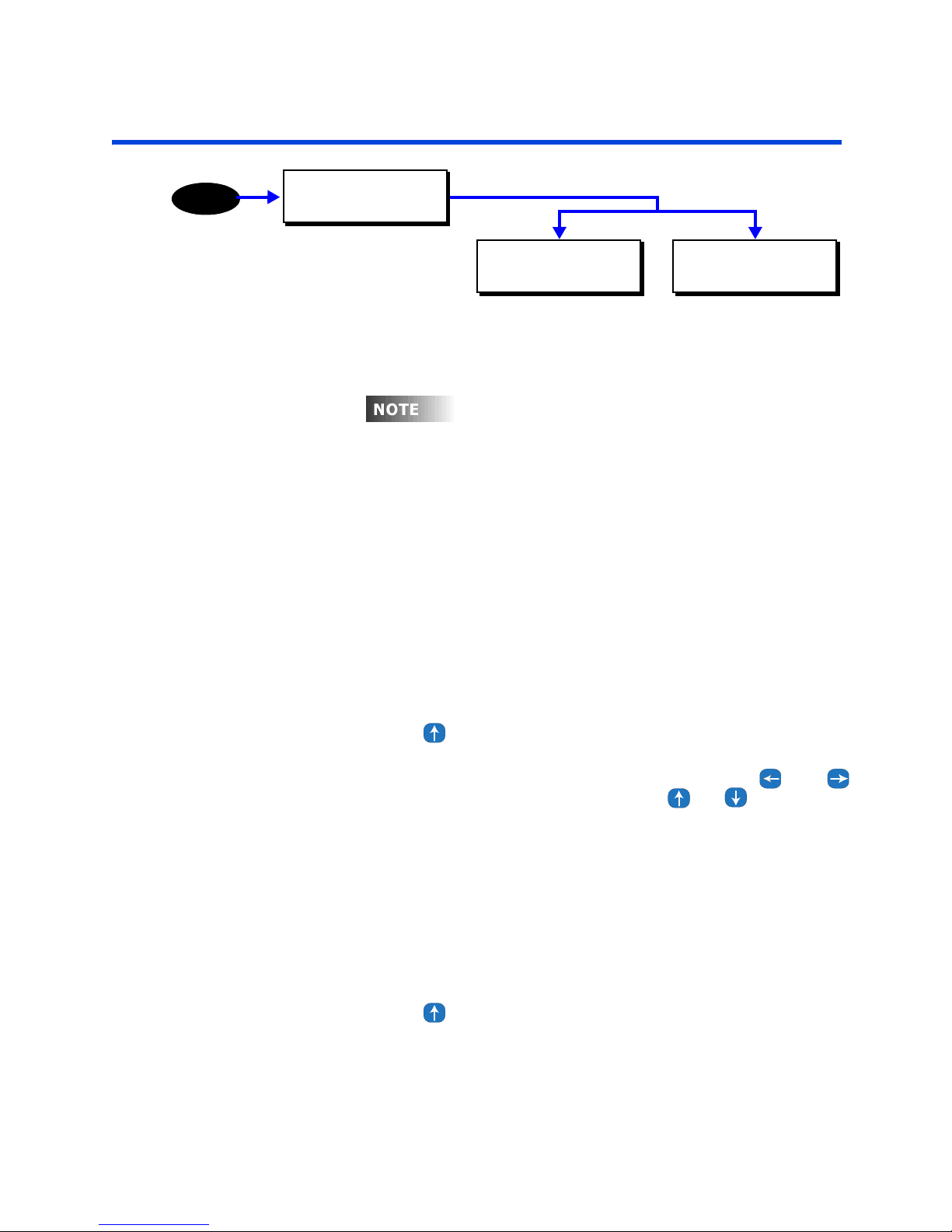
Action Editor
I
t
Action Editor
MENU
MAIN MENU SELECT
ACTION EDITOR
ACTION EDITOR
ADD/EDIT ACTIONS
The action editor is used to manage the actions defined in your relay cabinet. Actions
are used to execute commands or create groups of commands which are called by a
contact closure input or by the event scheduler.
n order to create any event, an action must firs
be created. The action is "what happens" the
event is "when it happens."
Each action is made up of a list of items. You can have as many action items as
desired, up to the system limit of 2000. There are four submenus in the Action Editor
• ADD A NEW ACTION
• EDIT AN ACTION
• DELETE AN ACTION
• EXIT (DONE)
ACTION EDITOR
DELETE AN ACTION
Adding an Action
Step 18: Navigate to the Action Editor
Step 19: Press until you get to the Add/Edit Actions Screen
Step 20: Press Select/Save
Step 21: Name the Action: You can change the name using the and
arrow buttons to move the cursor and the or arrow buttons
to change the character. You can also use the alpha-numeric keypad to
enter characters. Tapping the alpha-numeric button the first time will
result in the number, tapping the same button again will result in the
character listed above the number on the button. In the case of the 1
and 0 buttons, a hyphen or space character respectively will be
displayed. In the case of the number keys 2 - 9, the left most character
will be displayed. For these keys, as they are pressed repeatedly, each
successive character, from left to right is displayed until all have been
displayed, at which time it wraps back to the number and repeats.
Step 22: Press Select/Save when you have finished naming the Action
Step 23: Press until you get to the Add A New Item Screen
Z-Max Advanced Programming & Systems Design Guide rac00-sdg
Revision A:11/2005 Page 83
Page 94

ACTION CHOOSE TO
ADD A NEW ITEM
Step 24: Press Select/Save
The Following are the actions items that can be added:
• RLY (Relay)
• GRP (Group)
• BTN (Button)
• PHO (Photo Cell)
• OCC (Occupancy Sensor)
• ACT (Action)
• EVT (Event)
Step 25: Press until you get to the desired item
Step 26: Press Select/Save
Action Item Types:
Relay
ADDING NEW ITEM
RLY 01-01 REL De
This action item puts a relay or a range of relays into one of 5 states:
• REL: Relinquish releases control of the relay at the priority level specified. If
the action at this priority was currently in control of the relay, control will be
transferred to the next lower priority level action that is in any of the four other
states.
• OFF: Turns the relay off.
• ON: Turns the relay on.
• BWO: Activates the Blink Warn sequence for the selected relays provided Blink
Warn has been activated for each relay from the Setup Menu. See the Global
Default settings for Blink Warn timing settings.
• BWC: Cancels the Blink Warn operation for the selected relays.
Step 27: Press once to position the cursor in the first relay field
Step 28: Press and until you get to the desired starting relay
Step 29: Press once to position the cursor in the second relay field
Step 30: Press and until you get to the desired ending relay
Step 31: Press once to position the cursor in the relay state field
Step 32: Press until you get to the desired relay state (see above for the
types of states)
Page 84
Page 95
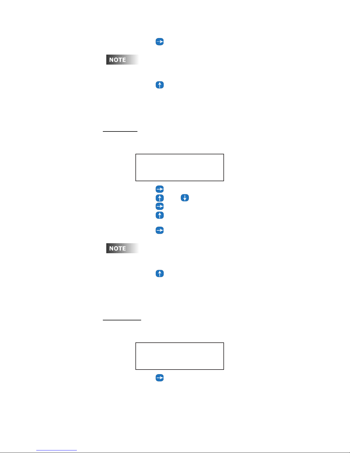
Step 33: Press once to position the cursor in the priority field
Any priority level from 1 to 16 can be selected (1 is the highest
priority). A priority of "De", for default, will use the default priority
that is set in the priority editor of the System Setup menu.
Step 34: Press until you get to the desired priority value
Step 35: Press Select/Save
The menu will be returned to the point where another item can be
added, edited, or deleted if desired.
Group - GRP
Any Group number can be assigned to an Action
ADDING NEW ITEM
GRP 0000 REL De
Action Editor
Step 36: Press once to position the cursor in the Group field
Step 37: Press and until you get to the desired Group number
Step 38: Press once to position the cursor in the Group state field
Step 39: Press until you get to the desired group state (see above for the
types of states)
Step 40: Press once to position the cursor in the priority field
Any priority level from 1 to 16 can be selected (1 is the highest
priority). A priority of "De", for default, will use the default priority
that is set in the priority editor of the System Setup menu.
Step 41: Press until you get to the desired priority value
Step 42: Press Select/Save
The menu will be returned to the point where another item can be
added, edited, or deleted if desired.
Button - BTN:
A switch (either local or networked) can be controlled via this action item.
ADDING NEW ITEM
Step 43: Press once to position the cursor in the Button Source Number
Z-Max Advanced Programming & Systems Design Guide rac00-sdg
Revision A:11/2005 Page 85
BTN:0000 000 REL
field
Page 96
Step 44: Press and until you get to the desired Button source number
or enter the number directly from the keypad.
A value of zero indicates a local input. A nonzero number indicates an
input on another networked cabinet
Step 45: Press once to position the cursor in the Button Number field
Step 46: Press until you get to the desired Button number or enter the
number directly from the keypad.
Step 47: Press Select/Save.
The menu will be returned to the point where another item can be
added, edited, or deleted if desired.
Photocell - PHO:
This action item is used to enable or disable a photo cell.
ADDING NEW ITEM
PHO 000 DISABLED
Step 48: Press once to position the cursor in the Photocell Number field
Step 49: Press and until you get to the desired Photocell number or
enter the number directly from the keypad.
Step 50: Press once to position the cursor in the Enable/Disable field
Step 51: Press and to toggle between ENABLE and DISABLE
Step 52: Press Select/Save.
The menu will be returned to the point where another item can be
added, edited, or deleted if desired.
Occupancy sensor - OCC:
This action item is used to enable or disable an occupancy sensor.
ADDING NEW ITEM
OCC 000 DISABLED
Step 53: Press once to position the cursor in the Occupancy Number field
Step 54: Press and until you get to the desired Occupancy number or
enter the number directly from the keypad.
Step 55: Press once to position the cursor in the Enable/Disable field
Step 56: Press and to toggle between ENABLE and DISABLE
Step 57: Press Select/Save.
The menu will be returned to the point where another item can be
added, edited, or deleted if desired.
Action - ACT:
An action item can call another action item. This menu allows you to set this up.
Page 86
Page 97
Be sure that you do not create a continuous loop by linking to action
items that eventually link back to the original
ADDING NEW ITEM
ACT undefined...
Step 58: Press once to position the cursor in the Action field
The default value is Undefined meaning no action has been selected!
Step 59: Press and until you get to the desired Action.
Press Clear to return to "undefined" once a number has been selected
Step 60: Press Select/Save.
The menu will be returned to the point where another item can be
added, edited, or deleted if desired.
Event - EVT:
This action item is used to enable or disable an event
Action Editor
ADDING NEW ITEM
EVT 001 DISABLED
Step 61: Press once to position the cursor in the Event Number field
Step 62: Press and until you get to the desired Event number or enter
the number directly from the keypad.
Step 63: Press once to position the cursor in the Enable/Disable field
Step 64: Press and to toggle between ENABLE and DISABLE
Step 65: Press Select/Save.
The menu will be returned to the point where another item can be
added, edited, or deleted if desired.
Edit an Item:
Once items have been added to an action, they can be edited. If you are still in the
Add An Action Section:
Step 66: Press until you get to the Edit An Action Screen
Step 67: Press Select/Save
Step 68: Press and to choose the action the item is in
Step 69: Press Select/Save
Step 70: Press until you get to Edit An Item Screen
Step 71: Press until you get to the item you want to edit
Step 72: Press Select/Save
Step 73: Edit the item using the same instructions that you used to create the
item
Step 74: When you are complete with the editing, Press Select/Save
The menu will be returned to the point where another item can be
added, edited, or deleted if desired.
Z-Max Advanced Programming & Systems Design Guide rac00-sdg
Revision A:11/2005 Page 87
Page 98
Delete an Item:
Once items have been added to an action, they can be Deleted.
Step 75: Press until you get to the Delete an Item Screen
Step 76: Press Select/Save
Step 77: Press and to choose the action the item is in
Step 78: Press Select/Save
Step 79: Press until you get to Delete An Item Screen
Step 80: Press until you get to the item you want to Delete
Step 81: Press Select/Save
RLY 01-01 REL De
DELETE Y/N? Y
Step 82: Press or to toggle between Y or N
Step 83: Press Select/Save
To exit the Item Editor
Step 84: Press until you get to the DONE Screen
Step 85: Press Select/Save
Editing and Deleting Actions
Once Actions have been created, they can be edited and deleted. From the Main
Menu
Edit an Action:
Step 1: From the Action Editor menus, press until you get to the Edit An
Action Screen
Step 2: Press Select/Save
Step 3: Press and to choose the action you want to edit
Step 4: Press Select/Save
Step 5: Edit the Name if you desire
Step 6: Press Select/Save
Step 7: Press until you get to the function you want to perform
Add an Item
Edit an Item
Delete an Item
Done
Step 8: Edit the item using the same instructions that you used to create the item
Step 9: When you are complete with the editing, Press Select/Save
The menu will be returned to the point where another item can be
added, edited, or deleted if desired.
Page 88
Page 99
Action Editor
Edit an Item:
Once items have been added to an action, they can be edited. From the Main Menu
Step 1: Press the Menu Button
Step 2: Press until you get to the Scheduler Screen
Step 3: Press Select/Save
Step 4: Press until you get to the Action Editor Screen
Step 5: Press Select /Save
Step 6: From the Action Editor, edit an action and the proceed to the edit actions
item menu and press Select/Save.
Step 7: Press and to choose the action of the item that you want to
edit.
Step 8: Press Select/Save
Step 9: Press until you get to Edit An Item Screen
Step 10: Press until you get to the item you want to edit
Step 11: Press Select/Save
Step 12: Edit the item using the same instructions that you used to create the
item
Step 13: When you are complete with the editing, Press Select/Save
The menu will be returned to the point where another item can be
added, edited, or deleted if desired.
Delete an Item:
Once items have been added to an action, they can be Deleted. From the Main Menu
Step 1: Edit an action and proceed to the action item menus. Select "Delete an
Item" and then and to choose the action the item you wish to
delete
Step 2: Press Select/Save
RLY 01-01 REL De
DELETE Y/N? Y
Step 3: Press or to toggle between Y or N
Step 4: Press Select/Save
Delete an Action
Step 1: From the action editor menu, choose the "Delete an Action" menu item.
Step 2: Press Select/Save
Step 3: Press and to choose the action you want to Delete
Step 4: Press Select/Save
Step 5: Press and to toggle between Y and N.
Step 6: Press Select/Save
Z-Max Advanced Programming & Systems Design Guide rac00-sdg
Revision A:11/2005 Page 89
Page 100

Page 90
 Loading...