

Page 1
evr-green
WEB VERSION
®
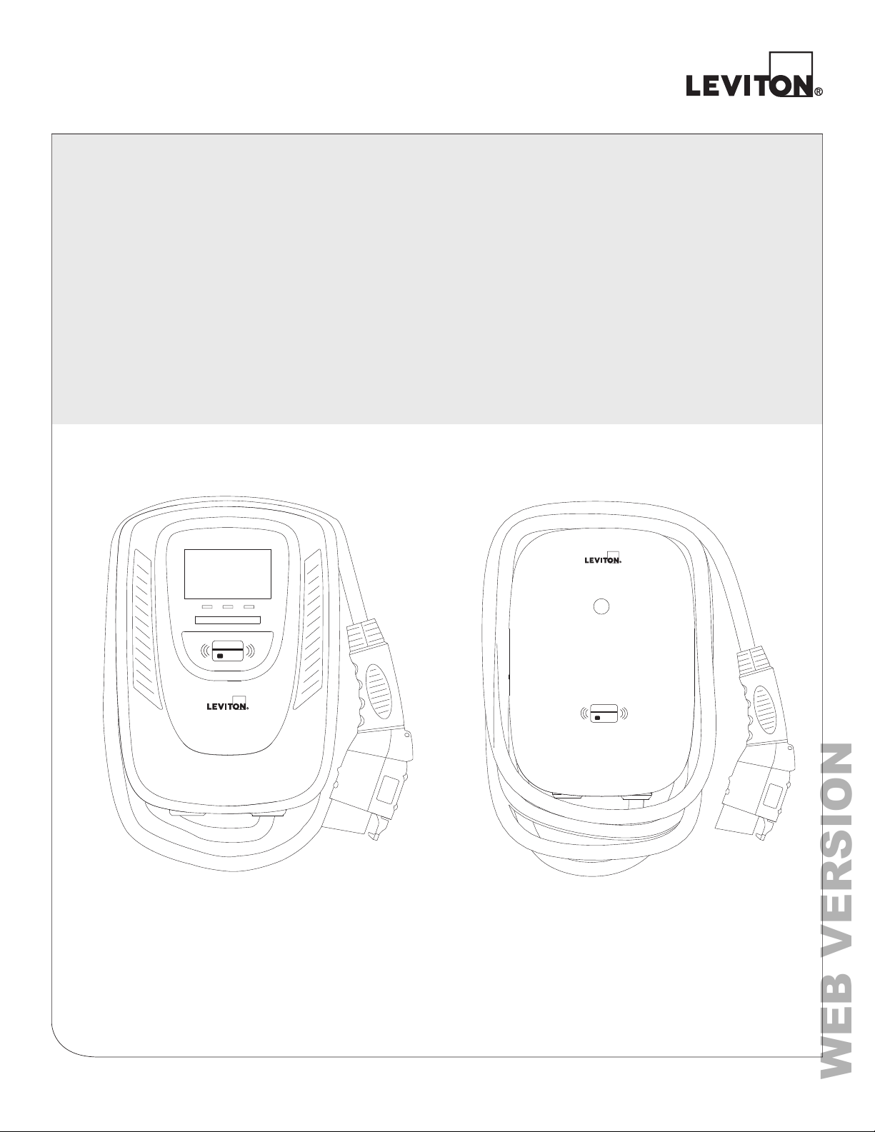
Electric Vehicle Charging Station
Installation Manual
Cat. Nos. EV320, EV32W, EV48W, EV48S
32A / 48A EVSE
PK-A3429-10-00-5A AR1372
Page 2

WEB VERSION
Page 3

TABLE OF CONTENTS
WEB VERSION
1 Warnings ........................................................................................................................................4
2 Safety and Specifications .............................................................................................................5
3 Tools Needed .................................................................................................................................6
4 Basic Interface ...............................................................................................................................7
5 Dimensions ....................................................................................................................................8
6 Status Light Key ............................................................................................................................9
6.1 Status Description of the Charger Indication Light ..............................................................9
7 Installation ....................................................................................................................................10
7.1 Wiring ......................................................................................................................................10
7.2 Wall-Mounted Bracket Installation .......................................................................................11
8 Operating Instructions ................................................................................................................12
8.1 Operating Procedures ............................................................................................................12
8.2 Operating Steps ......................................................................................................................12
8.3 To Restrict User Activation via RFID Card ............................................................................13
9 Error and Warning Messages ...................................................................................................... 15
10 Maintenance and Repair .............................................................................................................16
10.1 Daily Maintenance ................................................................................................................16
11 FCC and Warranty .......................................................................................................................17
Page 4
WEB VERSION
1 WARNINGS
Safety Instructions
WARNING: TO AVOID FIRE, SHOCK OR DEATH, TURN OFF POWER at the circuit breaker or fuse, and
test that the power is off before wiring! Do not remove circuit protective devices or any other component
until power is turned off.
WARNING: TO AVOID FIRE, SHOCK, SERIOUS INJURY, DEATH, OR DAMAGE TO THE CHARGER,
carefully read the charging instructions in your vehicle’s manual before charging and heed the following
warnings:
Failure to follow the safety instructions can result in risk of death, injuries and damage to the device! The
producer assumes no liability for claims resulting from this!
• Risk of electric shock. Do not remove cover or attempt to open the enclosure of the device. No user
serviceable parts inside.
• This device should be installed, adjusted, and serviced by qualified electrical personnel familiar with the
construction and operation of this type of charger and the dangers involved.
• The device is designed only for vehicles that are compatible with the SAE J1772 Level 2
charging standard.
• Do not install or use the charger near flammable, explosive, corrosive, or combustible materials,
chemicals, or vapors.
• Do not use the charger if it is defective, appears cracked, frayed, broken, or damaged.
• Do not use the charger when you are in the vehicle, or the charger is exposed to severe rain, snow, or
other severe weather.
• When transporting the charger, handle with care and do not drag or step on the device.
• Do not touch the charging connector terminal with sharp metallic objects for preventing damage.
• Do not forcefully pull the charging cable, damage it with sharp objects, put fingers, or insert foreign
objects into any part of the charging connector.
• Risk of explosion. This device has arcing or sparking parts that should not be exposed to
flammable vapors.
• Connect only to a circuit providing branch circuit overcurrent protection in accordance with the National
Electrical Code, ANSI/NFPA 70 (United States), the Canadian Electrical Code, Part I, C22.1. Canada),
or NOM-001-SEDE (Mexico)
EV320, EV32W 40 A
EV48W
Incorrect installation and testing of the charger could potentially damage either the vehicle’s battery and/or
the device itself. Any resulting damage is excluded from the warranty for the device
Ensure that the charging cable is well positioned during charging so it will not be stepped on, tripped over,
or subjected to damage or stress.
The device is designed only for vehicles that are compatible with the SAE J1772 Level 2 charging standard.
Model Circuit Breaker/Fuse Rating
, EV48S 60 A
4
Page 5
2 SAFETY AND SPECIFICATIONS
WEB VERSION
Design Safety Standards
UL2594: Electric Vehicle Supply Equipment
UL 2231-1: Personnel Protection Systems for Electric Vehicle (EV) Supply
Circuits: General Requirements
UL 2231-2: Personnel Protection Systems for Electric Vehicle (EV) Supply
Circuits: Particular Requirements for Protection Devices for Use in Charging Systems
UL 2251: Plugs, Receptacles and Couplers for Electric Vehicles
UL 62: Flexible Cords and Cables
UL 991: Tests for Safety-Related Controls Employing Solid-State Devices
UL 1998: Software in Programmable Components
NFPA 70 Article 625: National Electrical Code, Electric Vehicle Charging System
UL840 (Clearance and Creepage)
Specifications
Model Name EV320, EV32W, EV48W, EV48S
Rated Input Voltage 200-240 VAC / Single Phase
Rated Output Current 32A / 48A
AC Power Frequency 50/60 Hz
Input Protection UVP, OVP, RCD, SPD,Ground Fault Protection
Output Protection OCP, OTP, Control Pilot Fault Protection
Output Interface SAE J1772 AC Charging Connector
Storage Temperature -40°F(-40°C) to + 158°F(70°C)
Operation Temperature -22°F(-30°C) to + 122°F(50°C)
Relative Operation Humidity 95% RH Maximum
Relative Storage Humidity 95% RH Maximum
RJ45 Cable lnlet - LAN Version or Wi-Fi 10M / 100M Base-T
Wi-Fi Function - Wi-Fi Version 802.11 b/g/n
Cable Length 18 Ft.
Protection Level IK08 & IP54
Installation Type Wall mount or pedestal mount
Altitude < 2000 m
Weight 5.5 ± 0.5kg
Dimensions 350.52 mm. x 248.92 mm. x 129.54 mm.
Status Indication Red, Green, Blue LED
5
Page 6
3 TOOLS NEEDED
WEB VERSION
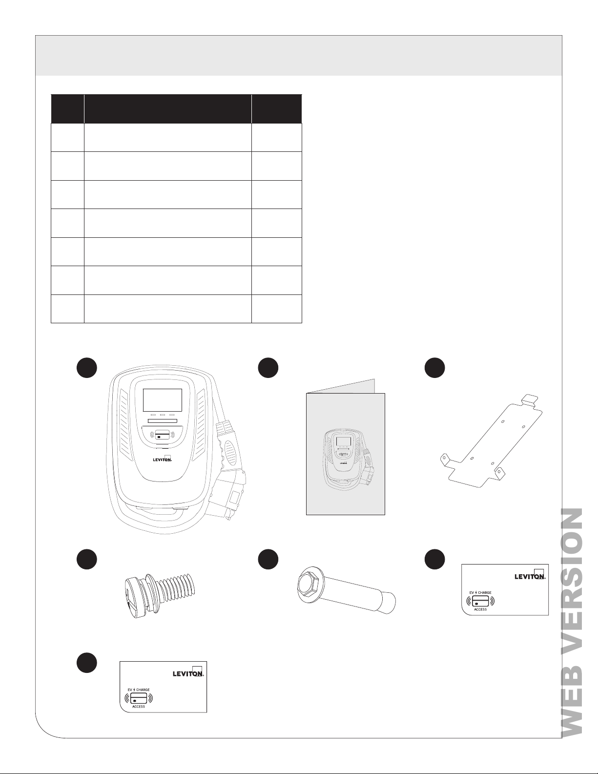
# Product Name Quantity
1 AC Charger (With Charging Cable) 1
2
3 Wall Mounted Bracket 1
4 M5 teeth screws 2
5 M6 Hexagonal Expansion Screws 4
6 Standard RFID Card 2
7 Administrator RFID card 1
1
User Manual 1
2
Tools required before installing
the Wall-Mounted charger:
• Wire stripper
• Phillips screwdriver
• Adjustable Wrench
• Voltmeter or digital multimeter
(for measuring AC voltage at the installation site)
• Level
• Pencil or marker
• Drill
3
Manual
4
5
6
Standard:
7
Admin:
6
Page 7
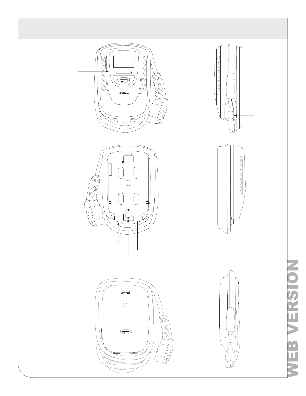
4 BASIC INTERFACE
WEB VERSION
EV48S
LED Light
Indication
Rear Notch
SAE J1772
AC Charging
Connector
EV320/
EV32W
EV48W
Charging
Cable Inlet
AC Power Inlet
LAN Cable Inlet
7
Page 8
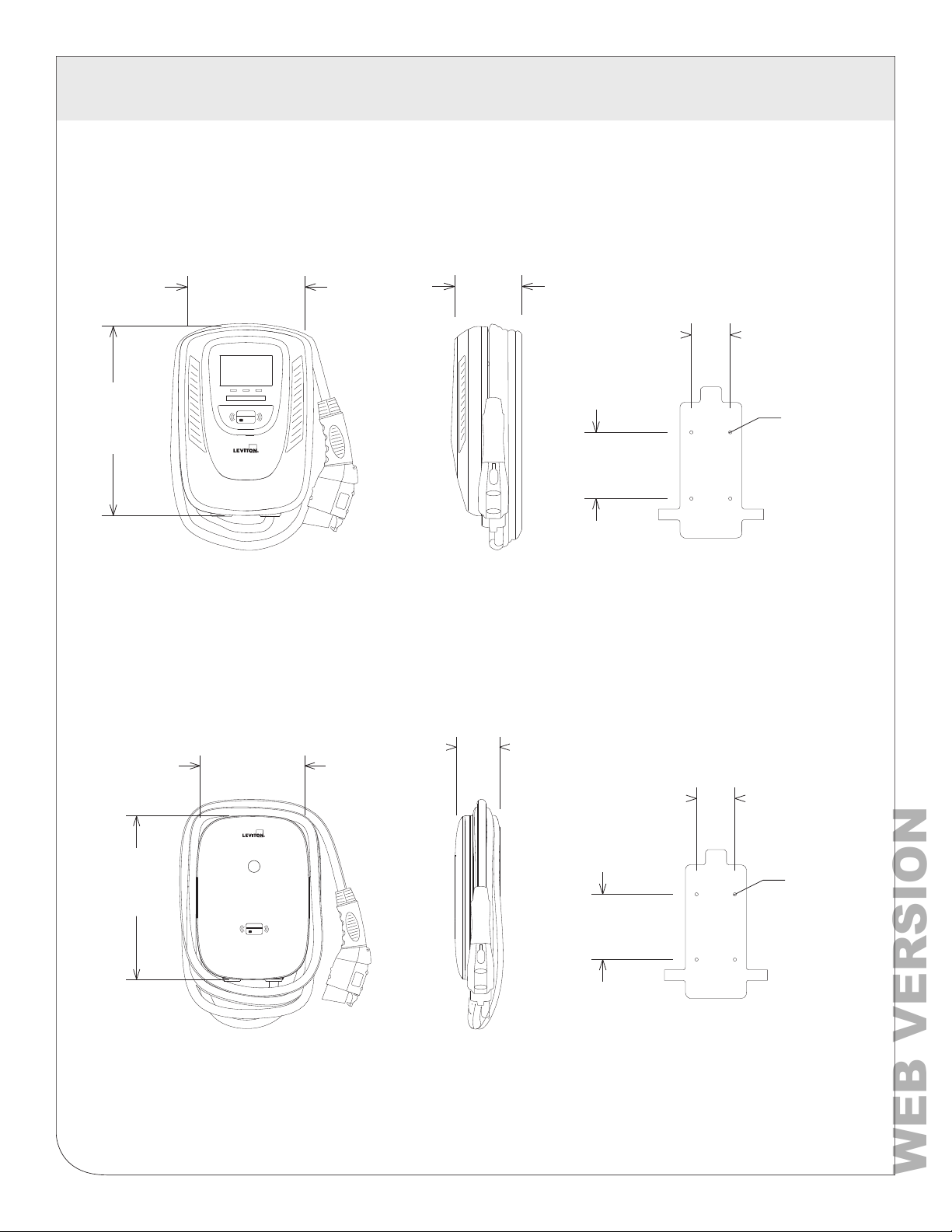
5 DIMENSIONS
WEB VERSION
Main Size of Charger - EV48S
9.8 in.
5.1 in.
13.8 in.
Main Size of Charger - EV320, EV32W and EV48W
Mounting Bracket
2.83 in.
Ø 0.35 in.
4.8 in.
14.2 in.
9.8 in.
3.9 in.
Mounting Bracket
2.83 in.
Ø 0.35 in.
4.8 in.
8
Page 9
6 STATUS LIGHT KEY
WEB VERSION
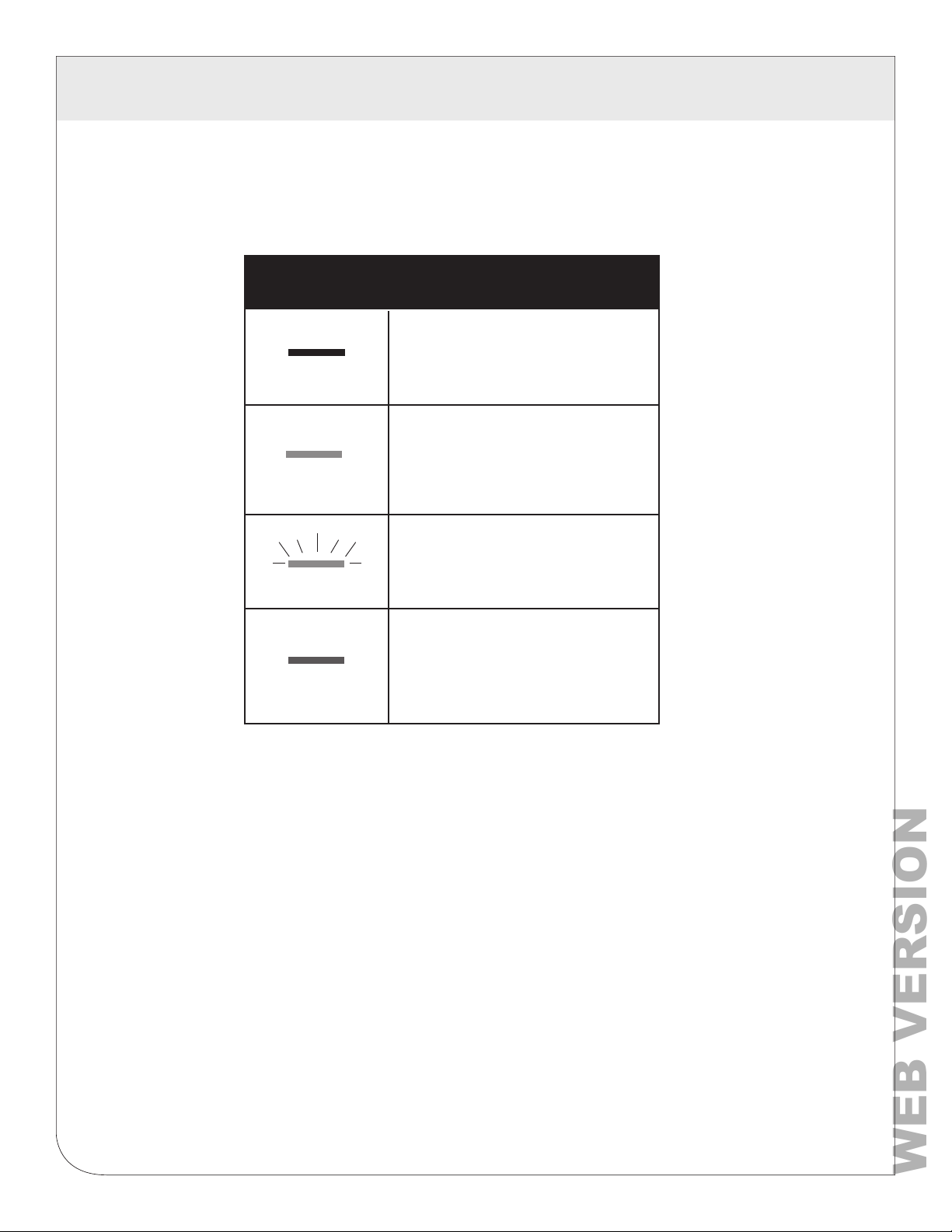
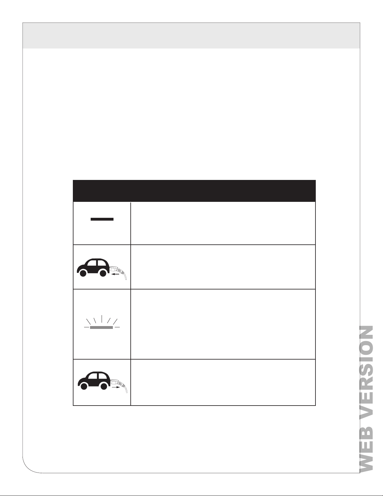
6.1 Status Description of the Charger Indication Light
Status of Charger Indication Light
Standby - Blue Light
READY
CHARGE
CHARGE
The READY light stays steady in
standby mode.
Waiting for Charge - Green Light
After the vehicle connector is
connected to the vehicle inlet,
the CHARGE light is constantly lit.
Charging - Green Light Flashing
The CHARGE light flashes while
charging
Fault - Red Light
FAULT
Safety Requirements:
• Be sure to preview the user manual and ensure local building and electrical codes
are reviewed before installing the AC charger.
• The AC charger should be installed by a qualified technician according to the user
manual and local safety regulations.
• Use appropriate protection when connecting to the main power distribution cable.
• Type B, C or D breaker with the rating current for table should be installed in the
upstream AC distribution box.
• Disconnect switch for each ungrounded conductor of AC input shall be provided by
others in accordance with the National Electrical Code, ANSI/NFPA 70.
The red light is lit while fault. Please
refer to section 9 “Error and Warning
Messages” for detailed information.
9
Page 10
7 INSTALLATION
WEB VERSION
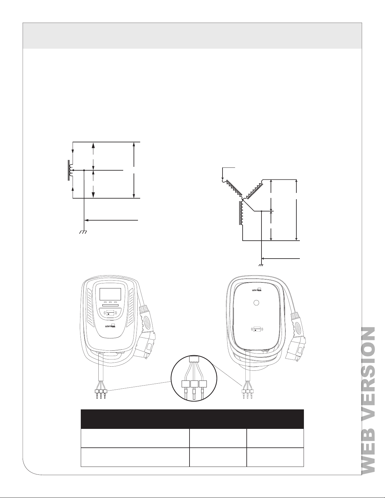
7.1 Wiring
240V Single Phase -
WARNING: The two phases used must
each measure 120V to Ground. Earth
ground must be connected to neutral at
only one point, usually at the breaker panel.
L1
120V
NEUTRAL
(NOT USED)
120V
240V
L2
GND
208V 3-Phase, Wye-Connected -
WARNING: The 208V feed is from a
y-connection power grid, and the AC charger
can connect to L1 and L2, L2 and L3, L1 and
L3. Earth ground must be connected to neutral
at only one point, usually at the breaker panel.
Leave the unused leg open. Do not connect it to
a Neutral bar, or to ground. Be sure the center
point is Earth ground somewhere in the system.
L3 (NOT USED)
L1
120V
120V
NEUTRAL
(NOT USED)
120V
L2
GND
L1 L2
PE
Output Amperage Amps 32A 48A
Circuit Breaker Options
L1 L2
PE
Circuit Breaker Options Table
Amps 40A 60A
10
L1 L2
PE
Page 11
7 INSTALLATION
WEB VERSION
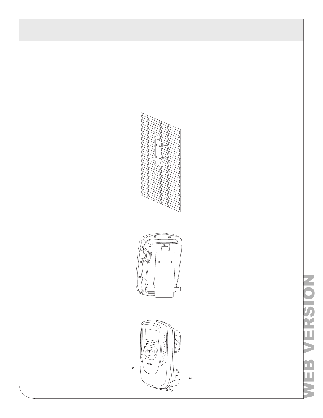
7.2 Wall-Mounted Bracket Installation
1.
• Set the positions of the four (4) screw holes and drill them, with a diameter of .35 in. (9 mm.) and
a depth of 2.05 in. (52 mm.).
• Use 4 sets expansion screw and M6 screw to fix the wall-mounted bracket on the wall.
• Use anchors appropriate for the wall substrate that you’re mounting to
2.
• Align the rear notch of charger into the wall-mounted bracket and fit the screw
holes of the right and left side.
3.
• Fix two M5 screws to complete the installation.
11
Page 12
8 OPERATING INSTRUCTIONS
WEB VERSION
8.1 Operating Procedures
• User authorization
• Connect to Vehicle Charging Inlet
• Charging Message
• Charging completed
NOTE: Device may need to be activated or de-activate with RFID cards. EV320 will be shipped with
RFID inactive. EV32W, EV48W and EV48S will be shipped standard with RFID active.
8.2 Operating Steps
NOTE: RFID access control is disabled by default on all units. See section 8.3 for
operation with RFID enabled
Operating Steps
1. Standby - Blue Light
After power-on, blue(READY), green(CHARGE) and red light
READY
(FAULT) all lit. Enter standby mode and the blue light (READY)
is steady on.The time from power on to
the green light on is 1.5 minutes.
CHARGE
2. Plug in Connector
Please plug the charging connector into the vehicle charging
inlet. when you tap the RFID card first, it needs to complete the
insertion of the charging connector within 2 minutes, otherwise
you need to tap the RFID card again.
3. Charging
The green light (CHARGE) turns to flash automatically,
charging is in process.
NOTE:
• If the red light (FAULT) is lit, plug-in the vehicle connector
again.
• If red light is still lit, please refer to “Error and
Warning Messages.”
4. Charging Finished
When charging is finished, the green light (CHARGE)
is constantly lit, press the button on connector to stop charging.
12
Page 13
8 OPERATING INSTRUCTIONS
WEB VERSION
8.3 To Restrict User Activation via RFID Card
Activation and Usage
NOTE: Activation of RFID access control is ONLY required when access to charging will be restricted
only for RFID card holders. If no restriction is required (open charging) this step is NOT required.
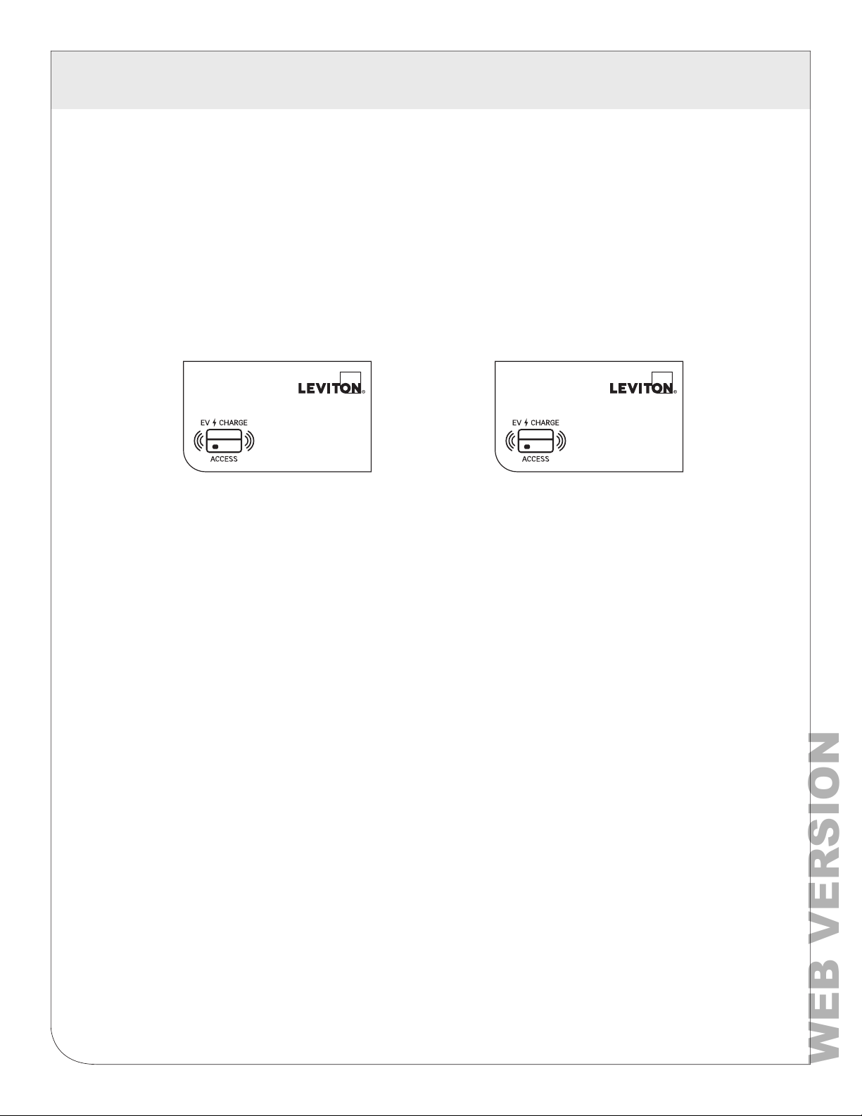
1. Identify Your Card
• All units come with 1 administrative (admin) card and 2 standard cards as marked on the cards
• Admin cards are used to activate RFID access control and should be kept by charger owner
• Standard cards are used to enable charging by users
Admin: Standard:
2. Activate RFID Access Control
WARNING: Once enabled, RFID access control cannot be disabled. If you prefer to keep this as an
unrestricted unit, do not activate this card.
• To enable RFID access control, hold the admin card to the RFID sensor image on the front of the
charger until you hear a beep. RFID access control is now enabled.
13
Page 14
8 OPERATING INSTRUCTIONS
WEB VERSION
8.3 To Restrict User Activation via RFID Card (Continued)
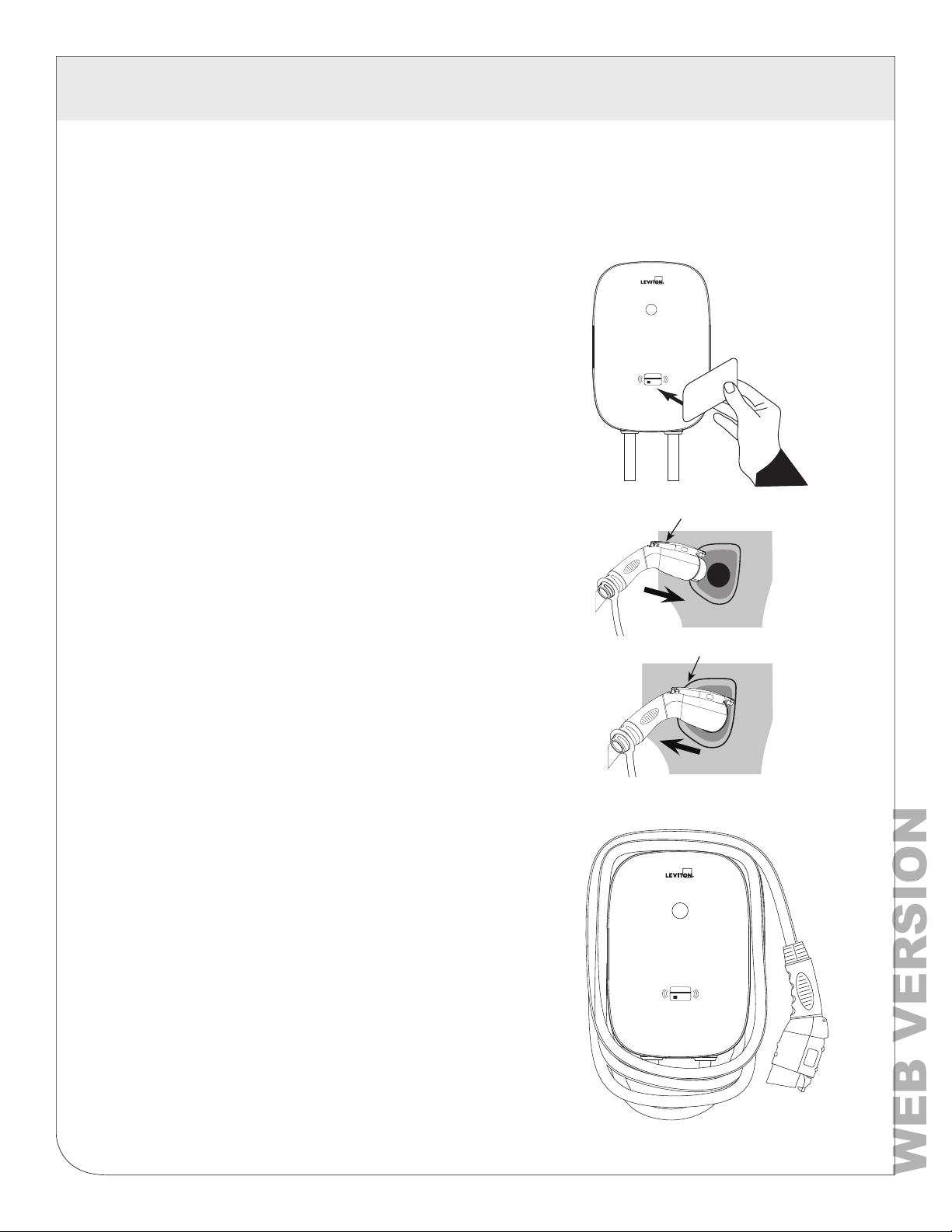
3. To enable charging with RFID card(s)
• Charging can be enabled with your standard RFID cards
1. Enable charging.
TAP your RFID card to the front of
the charger over the image of the
RFID. The POWER light will turn
solid green when the RFID card
has enabled the unit to charge.
2. Start charging.
Press and hold the black button on
the top of the charge plug and insert
it into the inlet on your car. Charging
starts automatically. The CHARGE
light will flash green.
Button
Button
3. How to stop and restart.
To stop charging, press black button on
top of charge plug to remove plug. To
restart charging, tap your RFID card,
press black button and reinsert.
4. After charging is complete.
NOTE: When charging is complete, loop
charging cable over station to prevent
tripping hazard.
NOTE: If the charging station is not
being used for an extended period
of time, it should be turned off.
14
Page 15
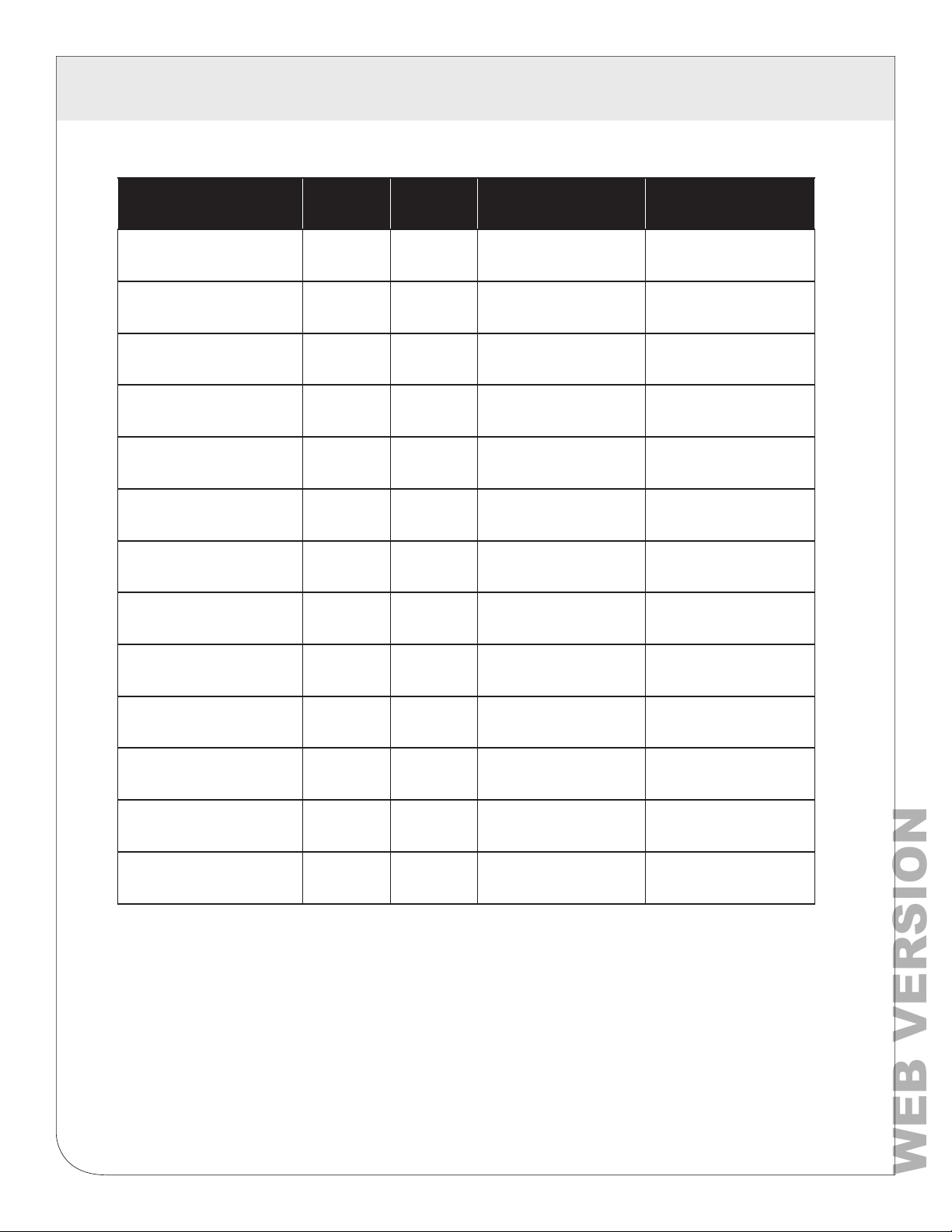
9 ERROR AND WARNING MESSAGES
WEB VERSION
Status Blue Green Red Remark
Input OVP - -
Input UVP
Output OCP - -
OTP - -
RCD Abnormal - -
Ground Fault - -
Control Pilot Fault - - Flicker Auto Recover
MCU Self-Test Fail - -
RCD Self-Test Fail - -
- -
1 flash followed
by 3 sec pause
2 flashes followed
by 3 sec pause
3 flashes followed
by 3 sec pause
4 flashes followed
by 3 sec pause
5 flashes followed
by 3 sec pause
6 flashes followed
by 3 sec pause
Constantly
Bright
Constantly
Bright
Auto Recover
Auto Recover
Auto Recover
Auto Recover
Auto Recover
Auto Recover
Auto Recover
Contact Customer
Service
Relay Self-Test Fail - -
RCD Abnormal
Stop Charging
Output OCP Stop
Charging
OTP
Stop Charging
--
--
--
Constantly
Bright
Constantly
Bright
Constantly
Bright
Constantly
Bright
Contact Customer
Service
Contact Customer
Service
Contact Customer
Service
Contact Customer
Service
15
Page 16

10 MAINTENANCE AND REPAIR
WEB VERSION
10.1 Daily Maintenance
WARNINGS
• Avoid moisture or water in the charger. If there is water or moisture, it is necessary to immediately
power off to avoid immediate danger, and notify professional personnel to carry out maintenance
before next use.
CAUTIONS
• Please keep the charger clean and in a clean area with low humidity.
Do not install it in an environment near the sea, with high oil, high humidity, or high dust.
• If there is any damage or dirt on the vehicle connector, charging cable, or vehicle connector
holder, please contact the maintenance personnel immediately.
• Please use the charger properly. Do not hit or press hard on the case. If the case is damaged,
please contact a professional technician.
• Avoid placing the charger near hot objects and at high temperature locations and away from
dangerous substances such as flammable gases and corrosive materials.
• Do not place external objects or heavy objects on the charger to avoid danger.
16
Page 17
11 FCC AND WARRANTY
WEB VERSION
FCC STATEMENT:
This device complies with Part 15 of the FCC Rules and ISED License-exempt RSS standard(s). Operation is subject to the following
two conditions: (1) This device may not cause harmful interference, and (2) This device must accept any interference received,
including interference that may cause undesired operation. Changes or modifications not expressly approved by Leviton could void
the user’s authority to operate the equipment.
These limits are designed to provide reasonable protection against harmful interference in a commercial installation. This equipment
generates, uses and can radiate radio frequency energy and, if not installed and used in accordance with the instructions, may cause
harmful interference to radio communications. However, there is no guarantee that interference will not occur in a particular installation.
If this equipment does cause harmful interference to radio or television reception, which can be determined by turning the equipment
off and on, the user is encouraged to try to correct the interference by one or more of the following measures:
- Reorient or relocate the receiving antenna.
- Increase the separation between the equipment and receiver.
- Connect the equipment into an outlet on a circuit different from that to which the receiver is connected.
- Consult the dealer or an experienced radio/TV technician for help.
This Class A digital apparatus complies with Canadian CAN ICES-3(A)/NMB-3(A)
FCC SUPPLIER’S DECLARATION OF CONFORMITY:
This device manufactured by Leviton Manufacturing Co., Inc. 201 North Service Road, Melville, NY 11747.
www.leviton.com. This device complies with part 15 of the FCC Rules. Operation is subject to the following two conditions: (1) This
device may not cause harmful interference, and (2) this device must accept any interference received, including interference that may
cause undesired operation.
TRADEMARK DISCLAIMER:
Leviton and the Leviton logo are trademarks of Leviton Manufacturing Co., Inc. Use herein of third party trademarks, service marks,
trade names, brand names and/or product names are for informational purposes only, are/may be the trademarks of their respective
owners; such use is not meant to imply affiliation, sponsorship, or endorsement.
Leviton Manufacturing Co., Inc.
201 North Service Road, Melville, NY 11747
Visit Leviton’s website at www.leviton.com
© 2022 Leviton Manufacturing Co., Inc. All rights reserved.
Specifications and price subject to change at any time without notice.
FOR CANADA ONLY
For warranty information and/or product returns, residents of Canada should contact Leviton in writing at Leviton Manufacturing of
Canada ULC to the attention of the Quality Assurance Department, 165 Hymus Blvd, Pointe-Claire (Quebec), Canada H9R 1E9
or by telephone at 1 800 405-5320.
Leviton warrants to the original consumer purchaser and not for the benefit of anyone else that this product at the time of its
sale by Leviton is free of defects in materials and workmanship under normal and proper use from the purchase date. Leviton’s
only obligation is to correct such defects by repair or replacement, at its option. For details visit www.leviton.com or call
1-800-824-3005. This warranty excludes and there is disclaimed liability for labor for removal of this product or reinstallation. This
warranty is void if this product is installed improperly or in an improper environment, overloaded, misused, opened, abused, or
altered in any manner, or is not used under normal operating conditions or not in accordance with any labels or instructions. There are
no other or implied warranties of any kind, including merchant ability and fitness for a particular purpose, but if any implied
warranty is required by the applicable jurisdiction, the duration of any such implied warranty, including merchantability and fitness
for a particular purpose, is limited. Leviton is not liable for incidental, indirect, special, or consequential damages, including
without limitation, damage to, or loss of use of, any equipment, lost sales or profits or delay or failure to perform this warranty
obligation. The remedies provided herein are the exclusive remedies under this warranty, whether based on contract, tort or otherwise.
For Technical Assistance Call: 1-800-824-3005 (USA Only) or 1-800-405-5320 (Canada Only) www.leviton.com
EV48S MODEL - 3 YEARS
EV320, EV32W AND EV48W MODELS - 2 YEARS
LIMITED WARRANTY AND EXCLUSIONS
17
Page 18

WEB VERSION
 Loading...