

Page 1
Single Pole Wide View Motion Activated Light Control
WEB VERSION
Cat. Nos. DOS02, DVS02 - INDOOR USE ONLY
Ratings: 120VAC, 60Hz 250 W Incandescent, 2 A Resistive, 150W LED and CFL, 250 VA ELV, 200VA MLV
WARNINGS
• TO AVOID FIRE, SHOCK OR DEATH: TURN OFF POWER AT CIRCUIT BREAKER
OR FUSE AND TEST THAT THE POWER IS OFF BEFORE WIRING!
• TO AVOID PERSONAL INJURY OR PROPERTY DAMAGE, DO NOT install to
control a receptacle, or a load in excess of the specified rating.
• To be installed and/or used in accordance with electrical codes and regulations.
• If you are not sure about any part of these instructions, consult an electrician.
INSTALLATION
Features
• Cat. Nos. DOS02 and DVS02 have a sensing angle of 180° and a
sensing area of coverage of 30 x 30 ft. See coverage diagram for details.
• Adjustable ambient light (DOS02 only), time delay and area of coverage
controls. See adjustment setting section for details.
• Indicator light alerts the user of device status.
• Adjustable time delay setting for 1, 5, 10 and 20 minutes plus a test mode
with 5 seconds on. A Temporary Bypass mode that disables the Auto-on
feature is available only for DOS02.
Mounting Location
• The device responds to temperature changes and care should be taken
when mounting the device.
• DO NOT mount directly above a heat source, in a location where hot or
cold drafts will blow directly on the sensor, or where unintended motion
(e.g., hallway traffic) will be within sensor's field-of-view.
You Will Need:
• Slotted/Phillips screwdriver
• Electrical tape
• Cutters
• Pliers
Installation
WARNING: TO AVOID FIRE, SHOCK OR DEATH, turn off power at circuit breaker or
fuse and test that the power is off before wiring.
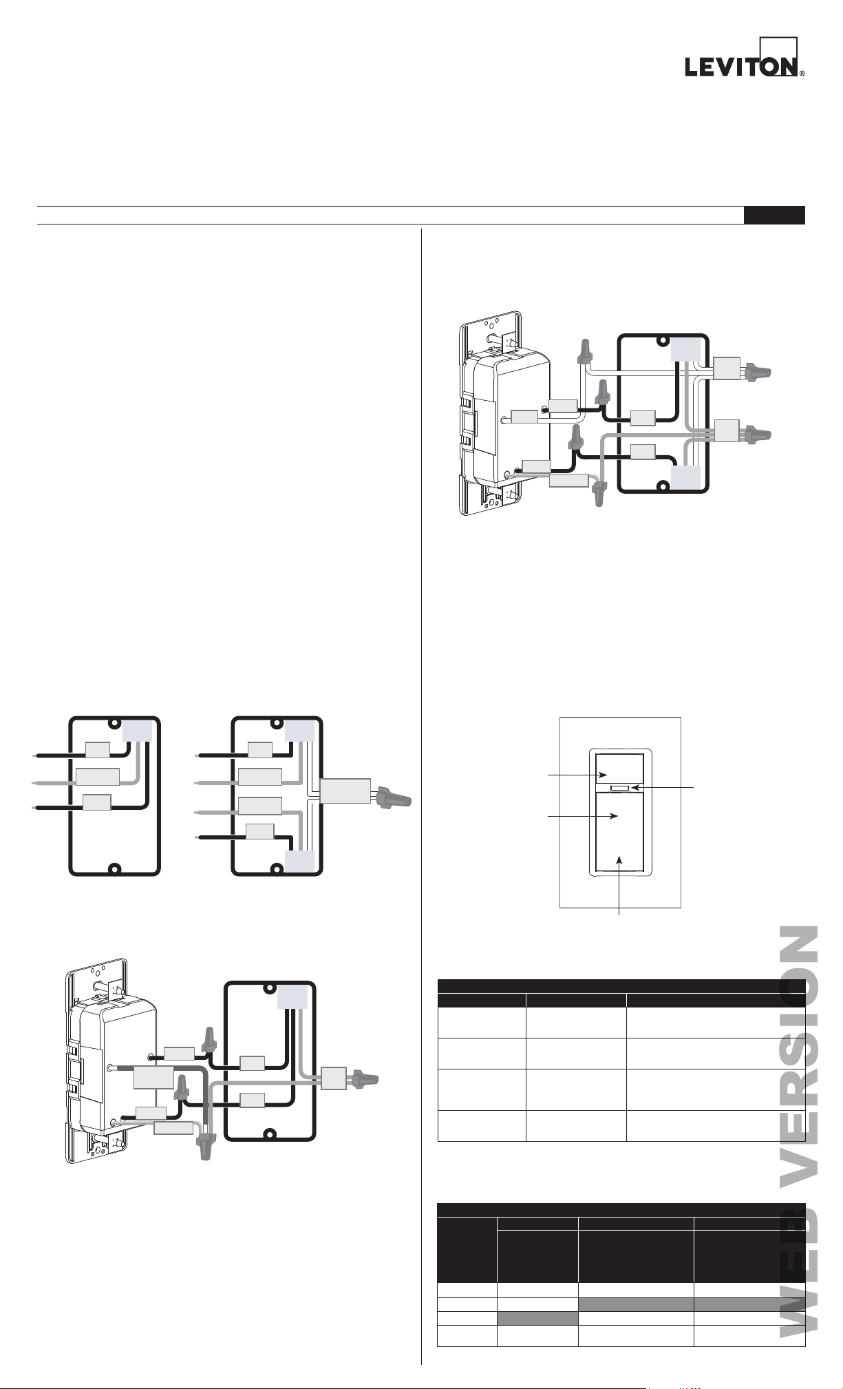
1. Identify your wires
(most common):
NOTE: Neutral wire (if present), or a Ground wire is required for operation. If
the wiring in the wall box does not resemble this configuration, consult an electrician.
CAUTIONS
• To clean use a damp cloth with mild soap. DO NOT use disinfecting products,
including foggers, sprays or other types of atomized cleaning agents.
• No user serviceable components. DO NOT attempt to service or repair.
• Use this device WITH COPPER OR COPPER CLAD WIRE ONLY.
PK-A3345-10-00-2A
ENGLISH
2b. Wire (when Neutral is present).
Remove the Green sleeve from the White wire. Working on one connection at a
time, connect wires as shown.
NOTE: This device is designed so the line and load wires can be wired
interchangeably.
NEUTRAL
LINE/LOAD
(White)
LINE/LOAD
(Black)
(Black)
GROUND
(Green/Yellow)
LINE
LOAD
GROUND
NEUTRAL
3. Test and mount.
• Restore power. Wait 10-20 seconds for sensor to power up.
• DOS02: Lights will automatically turn ON with first motion seen after warm up
period, or when push pad is pressed.
• DVS02: Lights will turn ON when push pad is pressed.
NOTE: If lights do not turn ON, refer to the "What to do if..." section.
Turn off power at circuit breaker before completing the installation.
• Gently push wires into wall box. Screw light control to box.
• Install wallplate.
• Restore power.
Operation
LINE
GROUND
LINE
GROUND
OR
LOAD
GROUND
LOAD
2a. Wire (when Neutral is NOT present).
Working on one connection at a time, connect wires as shown.
NOTE: This device is designed so the line and load wires can be wired
interchangeably.
LINE/LOAD
GROUND
(Green
sleeved
wire)
LINE/LOAD
(Black)
(Black)
GROUND
(Green/Yellow)
LINE
LOAD
NEUTRAL
GROUND
RED indicator light
(Will flash any time
motion is detected)
GREEN locator/
indicator light
(Turns ON when
TOP of button
load is OFF)
NOTE: Press either
TOP or BOTTOM of
button to turn ON/OFF.
BOTTOM of button
Programming
1. How to change the settings.
In order to... Do this... Indicator light will...
Enter programming
mode
Change settings
(Timer, Sensitivity,
Ambient Light)
Change options
within a setting
Save and exit
settings
NOTE: If there is no activity for 30 seconds, the device will automatically exit
programming mode and setting changes will not be saved. Multiple settings can be
saved by entering the programming settings once, selecting desired settings and then
saving and exiting.
Option
Number
Option 1 1 minute Low (50% Range) Low Light level
Option 2
Option 3
Option 4 20 minutes All settings to default
(Duration of time
for which load
is ON since last
detected motion)
How to choose a setting and option
Hold T
OP and BOTTOM
button for 5 seconds
Single press TOP button
= advance to the next
setting (see table below)
Single press BOTTOM
button = advance to the
next option
(see table below)
Hold either TOP or
BOTTOM button for
5 seconds
Setting Types and Options (defaults are in bold)
Setting 1 Setting 2 Setting 3
TIMER
(Sensitivity to motion –
adjusting the major and
minor detection range.)
5 minutes
10 minutes
GREEN light will be solid ON for 5 seconds
NOTE: If nothing happens, device is already in
RED light will blink to indicate setting selected
(Timer ->Sensitivity ->Ambient Light ->Timer)
GREEN light will blink to indicate option selected
(Option 1 ->Option 2 ->Option 3 ->Option 1)
GREEN light will be solid ON for 5 seconds
SENSITIVITY
Medium Medium Light level
High High/Brightest light level
programming mode
(Example: Setting 1 = 1 blink/sec)
Examples: Option 1 = 1 blink/sec
Option 2 = 2 blinks/sec
DOS02 only -
AMBIENT LIGHT
(If the room is brighter
than the setting selected,
the load will not turn ON.)
Disabled – turns ON for all
light levels
Page 2
Programming (cont'd)
OCC
VAC
WEB VERSION
2. When to use Occupancy or Vacancy.
Modes
Occupancy
(DOS02 only)
When to use
this setting
When
automatic ON/
OFF lighting
control is
desired.
Amount of
Ambient Light
Present
Low - Light
1.
will turn ON
automatically
if room is
darkest.
Medium- Light
2.
will turn ON
automatically
if room has
more light.
High - Light
3.
will turn ON
automatically
if room has
the most light
Disabled -
4.
Light will turn
ON always.
User walks into
the view of the
sensor when the
light is OFF and
it is darker than
the ambient light
level set.
OR
TOP or BOTTOM
of button is
pushed.
Turns light
ON when...
Light turns OFF
when...
No motion is
detected for the
duration of the
programmed time
period.
OR
TOP or BOTTOM
of button is
pushed.
3. Using advanced modes.
Mode name To enable this mode... The device will...
button.
seconds.
TOP of
Turn on the load for 5 seconds
every time motion is detected. RED
light will blink 1x/2 sec when in
Test Mode. Locator LED function
is disabled while motion detection
function is active.
Ignore motion keeping the light/load
off. GREEN light will double flash
every 2 seconds.
GREEN light will be solid ON
for 5 seconds. NOTE: If nothing
happens, device is already in
programming mode.
Test Mode
Temporary
Bypass Mode
(Available for
occupancy
sensors only)
Programming
Mode
(See Programming
directions above)
Press and hold
button for 5 seconds.
To exit, press TOP or
BOTTOM of button or
it will automatically exit
after 2 minutes.
Press and hold
BOTTOM of button for 5
seconds. To exit, press
TOP or BOTTOM of
Hold TOP and
BOTTOM of button for 5
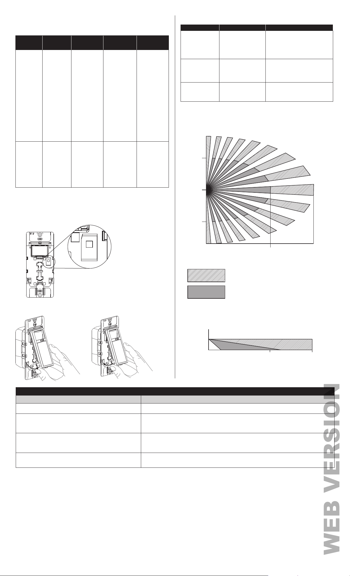
Sensing Area Coverage
1. Horizontal field of view:
15 FT
TOP or BOTTOM
When Manual
Vacancy
NOTE: When pressing the button to turn the light OFF manually, the sensor will
Occupancy/Vacancy Switch (DOS02 only)
Remove color kit and wallplate to access.
ON, Automatic
OFF lighting
control is
desired.
ignore motion for 30 seconds to allow user to exit the room (without retriggering the light).
OCC
VAC
N/A
of button is
pushed.
OR
User moves
around within 30
secs of the light
turning OFF.
TOP or BOTTOM
of button is
pushed.
OR
No motion is
detected for the
duration of the
programmed time
period.
Changing your device color
Remove Replace
10 FT
0
10 FT
15 FT
Major motion coverage 900ft
Minor motion coverage 400ft
2. Vertical field of view:
20 FT 30 FT
2
2
VAC
VAC
40-48 IN
20 FT 30 FT
What to do if...
Issue
Lights do not operate with push pad and RED indicator does not
blink when motion is present.
Lights do not switch ON when motion is detected (DOS02).
Lights always stay ON.
Lights do not turn ON (DVS02).
FCC STATEMENT: This device complies with Part 15 of the FCC Rules. Operation is subject to following two conditions: (1) this device may not cause harmful interference, and (2) this device must accept any interference received, including interference
that may cause undesired operation of the device. This equipment has been tested and found to comply with the limits for a Class B Digital Device, pursuant to Part 15 of the FCC Rules. These limits are designed to provide reasonable protection
against harmful interference in a residential installation. This equipment generates, uses, and can radiate radio frequency energy and, if not installed and used in accordance with the instructions, may cause harmful interference to radio communications.
However, there is no guarantee that interference will not occur in a particular installation. If this equipment does cause harmful interference to radio or television reception, which can be determined by turning the equipment OFF and ON, the user is
encouraged to try to correct the interference by one or more of the following measures:
• Reorient or relocate the receiving Antenna. • Increase the separation between the equipment and the receiver.
• Connect the equipment into an outlet on a circuit different from that to which the receiver is connected. • Consult the dealer or an experienced radio/tv technician for help.
FCC CAUTION: Any changes or modifications not expressly approved by Leviton Manufacturing Co., Inc., could void the user's authority to operate the equipment.
FOR CANADA ONLY
For warranty information and/or product returns, residents of Canada should contact Leviton in writing at Leviton Manufacturing of Canada Ltd to the attention of the Quality Assurance Department, 165 Hymus Blvd, Pointe-Claire (Quebec), Canada H9R
1E9 or by telephone at 1-800-405-5320.
LIMITED 5 YEAR WARRANTY For Leviton’s limited product warranty, go to www.leviton.com. For a printed copy of the warranty,call 1-800-824-3005.
Patents covering this product, if any, can be found on www.leviton.com/patents.
Leviton, the Leviton logo and Decora are the registered trademarks of Leviton Mfg. Co., Inc.
Make this adjustment
• Verify wiring connections to sensor.
• Motion is beyond sensing range - move closer to switch.
• Adjust the light level lower (Option 3, 2, 1 or disable).
• The RED light will blink to indicate motion. If it is blinking and the load is not turning ON, it could be due
to ambient light OR check to make sure that the Occ-Vac switch is in OCC position.
• Check time delay settings and compare to how long the lights stay ON.
• Make sure no motion occurs in coverage area for time selected by covering the lens.
• Check that switch is not installed near a heat source (like stove, lights, heat vents) or detecting motion
from an adjacent area (like hallway traffic) and if it is, relocate it.
• Make sure that control is installed correctly.
• Make sure the power is ON.
• Check to make sure the light bulb is functional.
© 2021 Leviton Mfg. Co., Inc.
For Technical Assistance Call: 1-800-824-3005 (USA Only)
or 1-800-405-5320 (Canada Only) www.leviton.com
PK-A3345-10-00-2A
 Loading...