

Page 1
RESET
RESET
TEST
TEST
1 2
0 3
ONOFF
ONOFF
ONOFF
ONOFF
ONOFF
ONOFF
ONOFFONOFF
ONOFF
ONOFF
ONOFF
ONOFF
2
4
3
1
White
Sensor
Terminal
Screw marked
Red (RD)
2
BK
RD
Terminal
Screw marked
Black (BK)
4
1
3
Single Pole Wide View Motion Activated Light Control
Cut
(if necessary)
Cat. No. IPS02, IPV02 - INDOOR USE ONLY
Ratings: 120VAC, 60Hz - 300W Incandescent - 150W LED, CFL - 200VA ELV, MLV - Fluorescent 2.5A - Resistive - 1/6th HP
INSTALLATION INSTRUCTIONS
WARNINGS AND CAUTIONS:
• TO AVOID FIRE, SHOCK, OR DEATH; TURN OFF POWER AT CIRCUIT BREAKER OR FUSE AND TEST THAT THE
POWER IS OFF BEFORE WIRING!
• To be installed and/or used in accordance with electrical codes and regulations.
• To avoid overheating and possible damage to this device and other equipment, DO NOT install to control a receptacle.
• DO NOT control a load in excess of specied ratings or you may damage property, or cause injury or death.
PK-93020-10-00-2B
WARNINGS AND CAUTIONS:
• If you are not sure about any part of these instructions, consult an electrician.
• Clean outer surface gently with damp cloth only. DO NOT use soaps or cleaning liquids.
• No user serviceable components. DO NOT attempt to service or repair.
• Use this device WITH COPPER OR COPPER CLAD WIRE ONLY.
Tools needed to install your Device
Slotted/Phillips Screwdriver Electrical Tape Pliers
Pencil Cutters Ruler
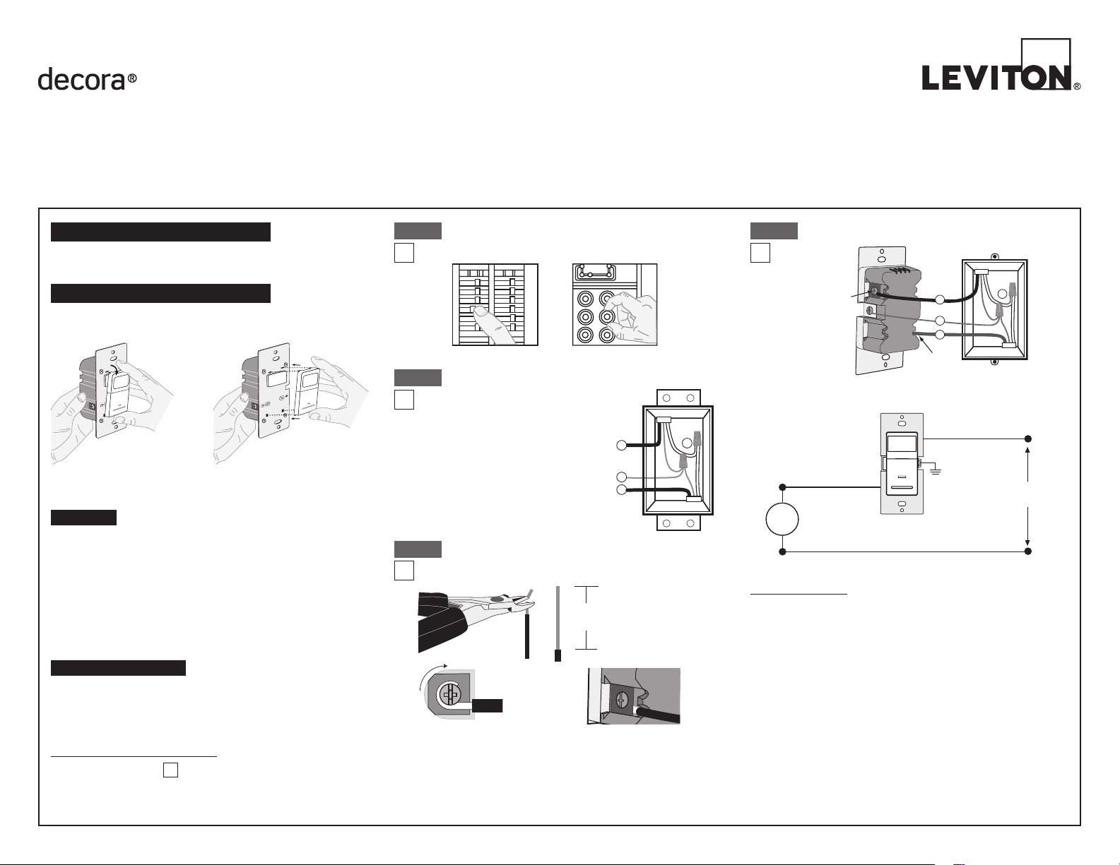
Changing the color of your device
Your device may include color options. To change color of the face
proceed as follows:
1 2
0 3
1 2
0 3
Push down tabs per
diagram, one at a time and
rotate forward to release
FEATURES
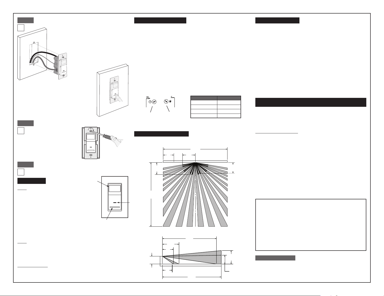
• Cat. No. IPS02 and IPV02 have a sensing area of coverage of 30 ft. x
30 ft., and a sensing angle of 180O (see Sensing Area Coverage gure
on page 2)
• Adjustable light and time-delay controls are located on the front of the
device. See adjustment setting section on page 2 for details.
• LED indicator is used to alert the user of the status of the device.
• Adjustable Time Delay setting for 30 seconds, 5 minutes,
15 minutes and 30 minutes.
• Occupancy sensors can be converted to vacancy sensors.
See Adjustment Section page 2.
LOCATION / MOUNTING
The device responds to temperature changes and care should be
taken when mounting the device. DO NOT mount directly above a heat
source, in a location where hot or cold drafts will blow directly on the
sensor, or where unintended motion (e.g., hallway trafc) will be within
sensor’s eld-of-view.
INSTALLING YOUR DEVICE
NOTE: Use check boxes when Steps are completed.
√
Attach new face by inserting
bottom hinge tabs, then pivot
and snap the color kit to attach
Step 1
WARNING: TO AVOID FIRE, SHOCK, OR DEATH;
TURN OFF POWER at circuit breaker or fuse and test
that power is off before wiring!
Step 2
Identifying your wiring application
(most common):
NOTE: If the wiring in the wall box
does not resemble any of these
congurations, consult an electrician.
Single-Pole
1. Line (Hot)
2. Neutral
3. Ground
4. Load
Step 3
Side Wire Connection
Side wire terminals accept #14-12
AWG solid copper wire only.
• Make sure that the ends of the wires from the wall box are straight
(cut if necessary).
• Remove insulation from each wire in the wall box as shown.
Preparing and connecting wires:
This device can be wired using side wire terminal screws.
Choose appropriate wire stripping specications accordingly.
5/8”
(1.6 cm)
Back Wire
Back wire openings use #14-12
AWG solid copper wire only.
Strip Gage
(measure bare wire
here or use gage on
back of the sensor)
BK
Step 4
Black
Single Pole Wiring Application:
Red
LOAD
Black
Green
Ground
Hot (Black)
120VAC, 60 Hz
Neutral (White)
Line
WIRING SENSOR:
Connect wires per WIRING DIAGRAM as follows:
NOTE: A ground connection is required to operate. Use the ground wire
in the electrical box for ground connection. If there is no ground wire,
make sure the electrical box is grounded and attach the ground wire to
the box with a screw.
• Green or bare copper wire in wall box to Green terminal screw.
• Line Hot wall box wire to terminal screw marked "BK".
• Load wall box wire to terminal screw marked "RD".
• Proceed to Step 5.
Page 2
30ft
9.1m
1.5m
1.4m
27ft
2.1m
1.2m
Step 5
Testing your Device prior to mounting in
wall box:
NOTE: Dress wires with a bend as
shown in diagram in order to relieve
stress when mounting device.
• Position all wires to provide room in
outlet wall box for device.
• Ensure that the word "TOP" is
facing up on device strap.
• Partially screw in mounting screws
in wall box mounting holes.
• Restore power at circuit breaker or fuse.
• Wait 40 seconds for sensor to power up.
• For IPS02, lights will automatically turn ON
after power is applied.
• For IPV02, press push pad. Lights should
turn ON.
If lights still do not turn ON, refer to the
TROUBLESHOOTING section.
Step 6
Device Mounting: TURN OFF POWER AT CIRCUIT
BREAKER OR FUSE.
Installation may now be
completed by tightening
mounting screws into wall
box. Attach wallplate.
Step 7
OPERATION
Restore Power: Restore power at circuit breaker or
fuse. Installation is complete.
Lens
IPS02
Auto On: Lights will automatically turn ON
when room is occupied or motion is detected.
The IPS02 will switch lights OFF when no
motion is detected in un-occupied room after set
period of time.
Time delay adjustment: Refer to section on
Adjustment settings.
The IPS02 will manually turn-on lights or the
load by depressing the ON/OFF paddle on the
Push
Pad
device. The IPS02 can be set to only turn ON by
the pushpad (no automatic ON operation) by adjusting the ambient light
control to the "0" position.
IPV02
Manual On: The IPV02 requires the user to manually turn-on lights or the
load by depressing the ON/OFF paddle on the device.
The lights or load will automatically turn-off when the room is left
un-occupied for a set period of time.
Time delay adjustment: Refer to section on Adjustment settings.
Locator Light LED:
LED blinks once every 2 seconds when motion is detected and if the load
is ON or OFF.
ADJUSTMENT SETTINGS
1. With power restored and wallplate removed, remove face of device to
expose setting controls, see color change instructions in page 1. Use
your nger or a small screwdriver to adjust the light sensitivity and time
settings on the device as follows:
Light Level Adjustment:
• Turn the control clockwise. Lights will turn ON in lighter conditions.
• Turn the control counter clockwise. Lights will turn ON in less lighting
conditions.
Time Selection:
• Adjust the time selector to the desired length of time the lights are to
remain ON. Lights will remain ON from 30 seconds to 30 minutes after
the room is vacated.
• Turn the control clockwise . Lights will remain ON up to 30 minutes.
• Turn the control counter clockwise. Lights will remain ON up to 30
seconds.
2. Test that the light level and time selection are as desired. If not, repeat
adjustments until satised.
3. Mount wallplate. INSTALLATION IS COMPLETE.
1 2
1 2
0 3
0 3
Time
Selection
NOTE: To operate the IPS02 as a vacancy sensor (Manual ON/Auto OFF):
rotate the light level sensitivity fully counter clock wise.
Light Level
Adjustment
Settings
0
1
2
3
Time
30 Sec
5 Min
15 Min
30 Min
SENSING AREA COVERAGE
Field-of-View (Horizontal)
9.1m
6ft
1.8m
5ft
Locator
Light
30ft
6ft
1.7m
5ft
1.5m
Side (Vertical) Field-of-View
8ft
2.6m
6ft
1.7m
4ft
5ft
1.5m
8.4m
30ft
9.1m
7ft
4ft
TROUBLESHOOTING
Lights do not operate with push pad and LED indicator does not
blink when motion is present:
• Ensure proper ground connection is present in the wallbox.
When conrmed, verify wiring connections to sensor.
Lights do not switch ON when motion is detected (IPS02):
• Motion is beyond sensing range, move closer to switch.
• Adjust the light level adjustment toward lighter (counterclockwise),
depending on room conditions.
Lights always stay ON:
• Check time delay settings and compare to how long the lights stay ON.
• Ensure that no motion occurs in coverage area for time selected.
• Check that switch is not installed near a heat source (e.g., stove, lights,
heat vents) or detecting motion from an adjacent area (e.g., hallway
trafc). If so, switch may have to be relocated.
Lights do not turn ON - IPV02:
• Check that control is installed correctly.
• Check that power is ON.
• Check that light bulb is functioning.
NOTE: If problems continue, consult an electrician.
For additional information, contact Leviton’s Techline at
1-800-824-3005 or visit Leviton’s website at www.leviton.com
This product is covered by U.S. Pat. No. 7,924,155 & corresponding foreign patents.
© 2015 Leviton Manufacturing Co., Inc. All Rights Including Trade Dress Rights Reserved
DECORA is a trademark of Leviton Manufacturing Co., Inc. registered in the United
FCC COMPLIANCE STATEMENT
This device complies with Part 15 of the FCC Rules. Operation is subject to following
two conditions: (1) this device may not cause harmful interference, and (2) this device
must accept any interference received, including interference that may cause undesired
operation of the device.
This equipment has been tested and found to comply with the limits for a Class B Digital
Device, pursuant to Part 15 of the FCC Rules. These limits are designed to provide
reasonable protection against harmful interference in a residential installation. This
equipment generates, uses, and can radiate radio frequency energy and, if not installed
and used in accordance with the instructions, may cause harmful interference to radio
communications. However, there is no guarantee that interference will not occur in a
particular installation. If this equipment does cause harmful interference to radio or
television reception, which can be determined by turning the equipment OFF and ON,
the user is encouraged to try to correct the interference by one or more of the following
measures:
• Reorient or relocate the receiving Antenna.
• Increase the separation between the equipment and the receiver.
• Connect the equipment into an outlet on a circuit different from that to which the
receiver is connected.
• Consult the dealer or an experienced radio/tv technician for help.
FCC CAUTION
Any changes or modications not expressly approved by Leviton Manufacturing Co., Inc.,
could void the user's authority to operate the equipment.
Leviton warrants to the original consumer purchaser and not for the benet of anyone
else that this product at the time of its sale by Leviton is free of defects in materials
and workmanship under normal and proper use for ve years from the purchase date.
Leviton’s only obligation is to correct such defects by repair or replacement, at its option.
For details visit www.leviton.com or call 1-800-824-3005. This warranty excludes
and there is disclaimed liability for labor for removal of this product or reinstallation. This
warranty is void if this product is installed improperly or in an improper environment,
overloaded, misused, opened, abused, or altered in any manner, or is not used under
normal operating conditions or not in accordance with any labels or instructions.
There are no other or implied warranties of any kind, including merchantability
and tness for a particular purpose, but if any implied warranty is required by the
applicable jurisdiction, the duration of any such implied warranty, including merchantability
and tness for a particular purpose, is limited to ve years. Leviton is not liable for
incidental, indirect, special, or consequential damages, including without limitation,
damage to, or loss of use of, any equipment, lost sales or prots or delay or
failure to perform this warranty obligation. The remedies provided herein are the
exclusive remedies under this warranty, whether based on contract, tort or otherwise.
FOR CANADA ONLY
For warranty information and/or product returns, residents of Canada should contact
Leviton in writing at Leviton Manufacturing of Canada Ltd to the attention of
the Quality Assurance Department, 165 Hymus Blvd, Pointe-Claire (Quebec),
Canada H9R 1E9 or by telephone at 1 800 405-5320.
States, Canada, Mexico and China.
LIMITED 5 YEAR WARRANTY AND EXCLUSIONS
PK-93020-10-00-2B© 2015 Leviton Mfg. Co., Inc.
 Loading...