

Page 1
Single Pole (One location) or 3-Way (Multi-location)
Fan Speed Control
Neutral (White)
For single pole installations, do not remove insulating label.
Fan Speed Control
Matching Remote (w/LEDs)
Matching Remote Fan Speed Control
Quiet Fan Speed Control
Cat. No. DDF01-BL
1.5A -120VAC, 60Hz
INSTALLATION INSTRUCTIONS
WARNINGS AND CAUTIONS:
• TO AVOID FIRE, SHOCK, OR DEATH: TURN OFF POWER at circuit breaker or fuse and test that power is off before wiring or servicing fixture!
• TO AVOID FIRE, SHOCK, OR DEATH: this control is to be used with ceiling fans that are rated 120VAC, total load 1.5 Amperes maximum.
• To be installed and/or used in accordance with appropriate electrical codes and regulations.
• If you are unsure about any part of these instructions, consult an electrician.
• Use this device with copper or copper clad wire only.
•
The Decora® DDF01 fan speed control is not compatible with standard 3-way or 4-way switches. It must be used with a Decora Digital remote for multi-location control, such as the DD00R-DL.
• Maximum wire length from fan speed control to all installed remotes cannot exceed 300 ft.
DI-000-DDF01-02A
WARNINGS AND CAUTIONS:
• For use on ceiling paddle fans with split-capacitor or shaded pole motors only. Please refer to manufacturer’s instructions or rating label on the motor to confirm type. Use with any other
types of motors or equipment may cause overheating and/or damage to the motors or equipment.
• Use only one (1) Fan Speed Control per load. The switch(es) will turn ON the fan at the speed level selected at the control.
• To avoid overheating and possible damage to this device and other equipment, DO NOT install to control a receptacle, fluorescent lighting, a motor or a transformer-operated appliance
other than appropriate ceiling fans.
INTRODUCTION
The next generation of fan speed control technology is here with the
new Decora Digital fan speed control with Bluetooth® technology. This
innovative device works using the Leviton Decora Digital Dimmer &
Timer app that can be easily downloaded to smartphones or tablets
and paired to the Leviton Fan Speed Control using Bluetooth®
technology. Decora Digital devices give users point-to-point local
control to automate lighting and fan speed control, bridging the gap
between standard dimmers, fan speed controls and whole-house
automation systems.
The Decora Digital fan speed control is a powerful device – combining
the best of Leviton fan speed functions with today’s mobile technology
for impressive results. The simple touch of a finger following the
intuitive on-screen guide makes it more convenient than ever to
manage fan speed.
Use of the app allows greater flexibility for accurate fan speed
functionality and makes pushing buttons for timed events a tedious
chore of the past.
The Leviton Decora Digital Dimmer & Timer app can be easily
downloaded to mobile devices and is compatible with Android and iOS
smartphones or tablets. The app is easy to use with simple, intuitive
on-screen menu options to independently control dimmers and
switches throughout the home.
Decora Digital devices are ideal for living rooms, bedrooms, kitchens,
dining rooms, home offices or anywhere full control of fan speed is
desired.
Compatibility:
Requires device with Bluetooth® 4.0 (BT LE) or later and iOS 6.0 and
later. Compatible with iPhone, iPad, and iPod touch or Android 4.0 and
later.
FEATURES
• ON/OFF LED and fan speed level LED
• Three way communication
• Ease of installation – No new wiring
TOOLS NEEDED FOR YOUR FAN SPEED CONTROL
Slotted/Phillips Screwdriver Electrical Tape Pliers
Pencil Cutters Ruler
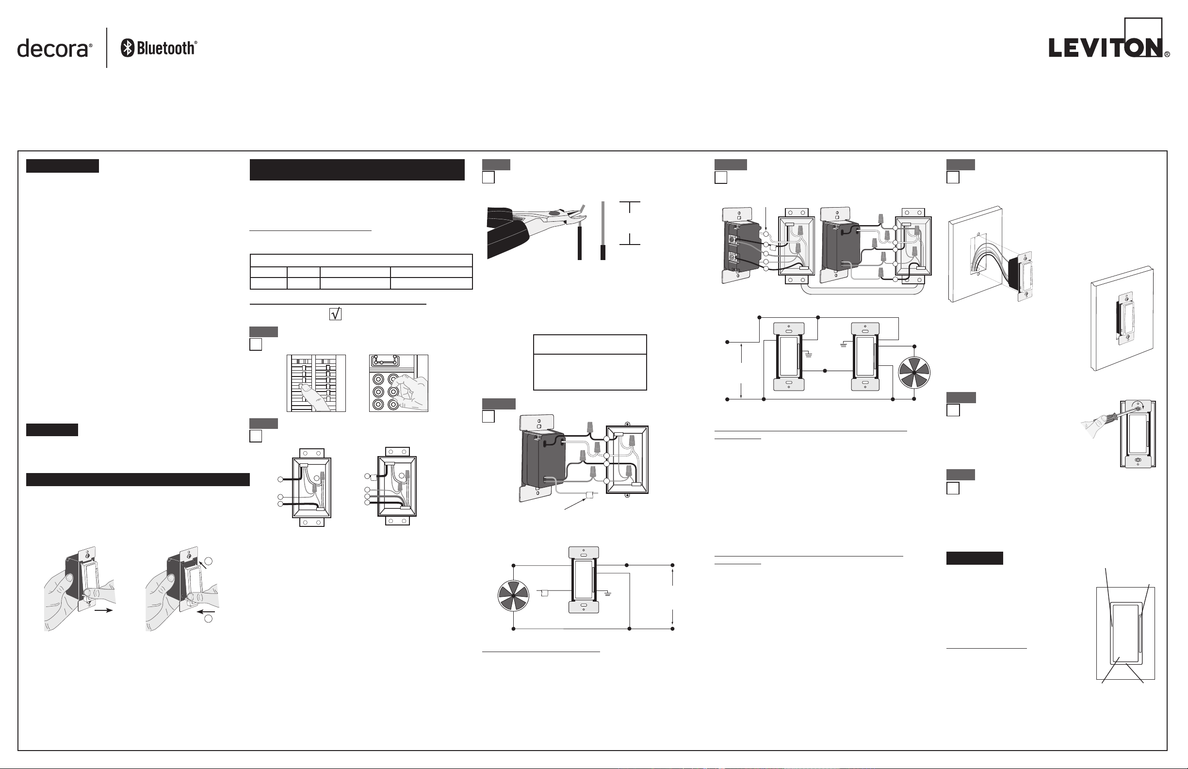
Changing the color of your Fan Speed Control:
Your device may include color options. To change color of the face
proceed as follows:
Push in sides at bottom
tabs and pull outward to
release
Insert top tabs and
press in bottom tabs
to attach
INSTALLING FAN SPEED CONTROL BY ITSELF OR
WITH OTHER DEVICES
If installing the Fan Speed Control in a single device application,
proceed with the INSTALLING YOUR FAN SPEED CONTROL section.
If installing Fan Speed Control in a multi-device application, proceed
as follows:
MULTI-DEVICE APPLICATION
In multi-fan speed control installations, there is no derating necessary.
Refer to the chart for maximum load per fan speed control.
MAXIMUM LOAD PER FAN SPEED CONTROL FOR MULTI-DEVICE
Cat. No.
DDF01
Single
1.5A
Two Devices
1.5A
More than 2 Devices
1.5A
INSTALLING YOUR FAN SPEED CONTROL
NOTE: Use check boxes when Steps are completed.
Step 1
WARNING: TO AVOID FIRE SHOCK OR DEATH; TURN
OFF POWER at circuit breaker or fuse and test that power
is off before wiring!
ONOFF
ONOFF
ONOFF
ONOFF
ONOFF
ONOFF
ONOFF
ONOFF
ONOFF
ONOFF
ONOFFONOFF
Step 3
Preparing and connecting wires:
Pull off pre-cut insulation from fan speed control leads. Make
sure that the ends of the wires from the wall box are straight
(cut if necessary). Remove insulation from each wire in the
wall box as shown:
5/8"
(1.6 cm)
Cut
Strip Gage
(measure bare
wire here)
(if necessary)
• Pull off pre-cut insulation from fan speed control leads.
• Make sure that the ends of the wires from the wall box are straight
(cut if necessary).
• Remove insulation from each wire in the wall box as shown.
• For Single-Pole Application, go to Step 4a.
• For 3-Way Matching Remote (w/LEDs) Application, go to Step 4b.
For non-standard wiring applications, refer
to Wire Connector and Conductor Size Chart
WIRE CONNECTOR / # OF COND.
COMBINATION CHART
1 - #12 w/ 1 to 3 #14, #16 or #18
2 - #12 w/ 1 or 2 #16 or #18
1 - #14 w/ 1 to 4 #16 or #18
2 - #14 w/ 1 to 3 #16 or #18
Step 4a
Single Pole Wiring Application:
Step 4b
120VAC, 60Hz
3-Way Wiring with DD00R Matching Remote
(w/LEDs) Application:
Additional Neutral Wire
2
Hot (Black)
Line
Neutral (White)
1
4
3
5
WH BK
YL/RD
Green
Ground
Yellow/
Red
Green
Ground
Red
Green
Yellow/Red
Black
White
Black
Red
White
Step 5
Testing your Fan Speed Control prior to
mounting in wall box:
• Position all wires to provide room
in outlet wall box for device.
• Ensure that the word “TOP” is
facing up on device strap.
• Partially screw in mounting screws
4
2
1
3
5
in wall box mounting holes.
NOTE: Dress wires with a bend as
shown in diagram in order to relieve
stress when mounting device.
• Restore power at circuit breaker or fuse.
• Press pad until locator light is OFF. Fan
should turn ON. If the fan does not turn
ON, press the TOP half of the Fan Speed
Black
Bar until the fan speed increases.
If the fan still does not turn ON, refer to
the TROUBLESHOOTING section.
White
Step 6
Fan Speed Control Mounting:
TURN OFF POWER AT
CIRCUIT BREAKER OR FUSE.
Step 2
1
IMPORTANT: For 3-Way applications, note that one of the screw
2
terminals from the old switch being removed will usually be a different
color (Black) or labeled Common. Tag that wire with electrical tape and
identify as the common (Line or Load) in both the fan speed control wall
box and remote wall box.
Identifying your wiring application (most common):
NOTE: If the wiring in your wall box does not resemble any
of these configurations, consult an electrician.
1
3
4
2
Single Pole
1. Line (Hot)
2. Neutral
3. Ground
4. Load
1
3
4
5
3-Way
1. Line or Load
(see important
instruction)
2. Neutral
3. Ground
4. First Traveler – note color
5. Second Traveler – note color
2
Black
White
Red
Green
Yellow/Red
Insulating label:
This wire is used in 3-way installations only.
Red
Black
Yellow/Red
Insulating
Label
White
1
2
4
3
White
Green
Ground
Hot (Black)Black
Line
120 VAC,
60Hz
WIRING FAN SPEED CONTROL:
Connect wires per WIRING DIAGRAM as follows:
NOTE: The DDF01 Fan Speed Control requires a neutral wire connection.
• Green or bare copper wire in wall box to Green fan speed control lead.
• Line Hot wall box wire to Black fan speed control lead.
• Load wall box wire to Red fan speed control lead.
• Line Neutral wall box wire to White fan speed control lead.
WIRING MATCHING REMOTE (wall box with line hot
connection):
Connect wires per WIRING DIAGRAM as follows:
NOTE: The matching remote must be installed in a wall box with a Line
Hot connection and a Neutral connection. A Neutral wire to the matching
remote needs to be added as shown.
NOTE: Maximum wire length from fan speed control to all installed
remotes cannot exceed 300 ft (90 m).
• Green or bare copper wire in wall box to Green terminal screw.
• Line Hot (common) wall box wire identified (tagged) when removing old
switch and First Traveler to Remote terminal marked "BK".
• Second Traveler wall box wire from fan speed control to remote terminal
screw marked "YL/RD" (note wire color). This traveler from the remote
must go to Yellow/Red fan speed control lead.
• Line Neutral wall box to remote terminal screw marked "WH".
WIRING FAN SPEED CONTROL (wall box with load
connection):
Connect wires per WIRING DIAGRAM as follows:
NOTE: The DDF01 fan speed control must be installed in a wall box that
has a Load connection and a Neutral connection.
•
Green or bare copper wire in wall box to Green fan speed control lead.
• Load wall box wire identified (tagged) when removing old switch to Red
fan speed control lead.
• First Traveler Line Hot to Black fan speed control lead.
• Remove Red insulating label from Yellow/Red fan speed control lead.
• Second Traveler wall box wire (note color as above) to
Yellow/Red fan speed control lead. This traveler from the fan speed
control must go to the terminal screw on the remote marked "YL/RD".
• Line neutral wall box wire to White fan speed control lead.
• Proceed to Step 5.
Installation may now be completed by
tightening mounting screws into wall box.
Attach wallplate.
Step 7
Restore Power:
Restore power at circuit breaker or fuse.
Installation is complete.
N
OTE: To pair your fan speed control with your mobile device,
download the Leviton Decora Digital Dimmer and Timer app from the
Google Play Store or your iTunes account. Contact Leviton’s Techline
at 1-800-824-3005 or visit Leviton’s website at www.leviton.com for
additional information.
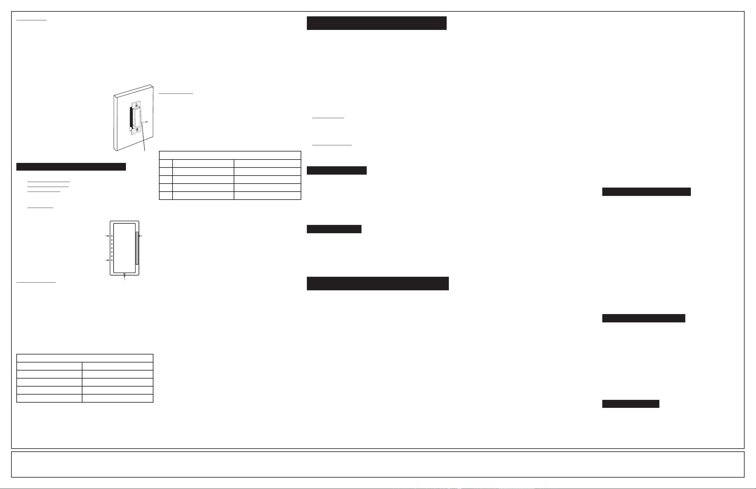
OPERATION
NOTE: The locator light will illuminate when
the load is in the OFF position to facilitate
LED Fan Speed
Display
Fan Speed
Bar
access in the dark.
NOTE: If using the fan speed control in a
3-way application, the fan will turn ON at the
speed set on fan speed control bar. The fan
can be controlled from either the fan speed
control, the remote location or the mobile
device app.
Rocker (Default settings)
Turn ON from OFF position:
Tap TOP of Rocker: Fan turns ON to preset
level.
Turn OFF from ON position:
Tap BOTTOM of Rocker. Fan turns OFF.
Rocker
Locator
Light
• Yellow/Red fan speed control lead should have Red insulation
label affixed.
NOTE: If insulating label is not affixed to Yellow/Red fan speed control
lead, use electrical tape to cover.
• Proceed to Step 5.
Page 2
Fan Speed Bar
INCREASE:
Press the TOP half of the Fan Speed Bar – Fan speed increases to
desired level.
DECREASE:
Press the BOTTOM half of the
to desired level.
If you continue to hold, the fan speed level decreases
Fan Speed Bar
–
Fan speed decreases
to the minimum level and then turns OFF.
NOTE: When the fan is OFF you can change the fan speed level that
the fan will turn ON to using the Fan Speed Bar. If there is a power
outage, when the power is restored, the fan speed will return to the last
setting before the power interruption.
Air-Gap Switch: On the fan speed control only,
engage the air-gap switch by gently pulling out
from the bottom of the Fan Speed Bar until the
bottom of the bar lifts completely out of the frame
and a click is heard (refer to Figure). LED's will
turn OFF. This will stop power to the fixture. After
servicing is complete, press the Fan Speed Bar
back into place for normal operation.
Cleaning: Clean with a damp cloth.
DO NOT use chemical cleaners.
Gently pull out
from bottom
ADVANCED PROGRAMMING FEATURES
Definition of A Modes
A-1) Maximum Fan Speed: Sets the maximum fan speed level.
A-2) Minimum Fan Speed: Sets the minimum fan speed level.
A-3) Preset ON Level: Sets the turn on fan speed level regardless of
the previous set fan speed level.
Definition of B Modes
B-1) LED Options: Sets the time period in seconds the Locator LED
and Fan Speed display will stay on before extinguishing.
Definition of LEDs
Bottom LED = LED 1
Top LED = LED 7
NOTES:
• The device will exit programming
mode after 3 minutes of inactivity.
• Pressing the TOP of the Rocker at
any time during programming will
advance the device to the next
programming mode.
Program Mode A
To enter Program Mode A:
Press and hold the TOP of the Rocker and the TOP of the Fan Speed
Bar simultaneously for 5 seconds until the Locator LED begins to blink.
A-1) Maximum Fan Speed Level: The Locator LED will blink 1 time per
second to indicate the device is in Program Mode A-1, Maximum
Fan Speed Level.The default mode is 100% i.e. full fan speed. To
change the fan speed level, use the Fan Speed Bar to move the
corresponding LED to the desired discreet preset level according
to the Maximum Fan Speed Chart. By tapping the TOP of the
Rocker this setting will automatically be saved and the device
will advance to the next Programming Mode, A-2, Minimum Fan
Speed Level.
MAXIMUM FAN SPEED CHART
When indicator is at LED # Fan speed is at
7 Max
5 High
3 Medium
1 Low
LED 7
LED 1
Locator LED
Fan
Speed
Bar
A-2)
The Locator LED will blink 2 times per second to indicate the device is in
Program Mode A-2, Minimum Fan Speed Level. The default Minimum
fan Speed Level is LED 2. To change the Minimum Fan Speed Level
from 1-50%, use the Fan Speed Bar. The fan speed will reflect the
minimum fan speed level selected. By tapping the TOP of the Rocker
this setting will automatically be saved and the device will advance to the
next programming mode, A-3, Preset ON Level.
A-3)
The Locator LED will blink 3 times per second to indicate Program
Mode A-3, Preset ON Level. To change the current Preset ON
Level from 1-100%, use the Fan Speed Bar. If this feature is not
desired, press and hold the BOTTOM half of the Fan Speed Bar
until no LED is lit (default setting). By tapping the TOP of the Rocker
this setting will automatically be saved and the device will exit
Programming Mode A.
Program Mode B
To enter Program Mode B:
Press and hold the TOP of the Rocker and then the BOTTOM of the Fan
Speed Bar for 5 seconds until the Locator LED and the TOP LED (LED 7)
begin to blink.
B-1)
The Locator LED will blink 1 time per second to indicate Program
Mode B-1, LED Options. To change the LED Options settings, use
the Fan Speed Bar to move the LED to the desired preset setting
according to the LED Options Chart. By tapping the Top of the
Rocker this setting will automatically be saved and the device will exit
Programming Mode B.
LED OPTIONS CHART
LED Locator LED Timeout LED Fan Speed Display Options
7 Turns OFF 5 seconds after use Turns OFF 5 seconds after use
5 Turns OFF 5 seconds after use Active
3 Active Turns OFF 5 seconds after use
1 Active Active
CONTROLLING YOUR FAN SPEED CONTROL WITH
BLUETOOTH
®
Download the Leviton Decora Digital Dimmer & Timer App for
your device.
Android: Tap the Google Play Store icon on your phone or go to
http://play.google.com on your computer and follow the
instructions to obtain the app.
iPhone: Tap the App Store icon on your phone or access the app
through your iTunes account on your computer.
Once you have downloaded the app, follow the instructions on the screen
to pair your mobile device with your fan speed control. Once your mobile
device is paired, use the following options to control your fan speed:
• On - Off: Turns the fan speed control ON and OFF.
• Schedule: Creates distinct ON/OFF events based on time and day.
• Sleep Timer: Sets countdown to turn fan speed control OFF.
Advanced Settings
Device Options
• Hide LED Fan Speed Bar: Turns LED Fan Speed Bar OFF.
• Hide Status LED: Turns Status LED OFF.
• DST Offset Hours: Adjusts the Sunrise/Sunset time in hours.
• DST Offset Minutes: Adjusts the Sunrise/Sunset time in minutes.
Fan Speed Options
• Preset: Sets the fan speed level at which the fan turns ON.
• Minimum: Sets a minimum fan speed level.
• Maximum: Sets a maximum fan speed level.
TROUBLESHOOTING
• Fan does not turn ON and Locator LED does not turn ON
- Circuit breaker or fuse has tripped.
- Fan is burned out.
- Neutral not wired to Fan Speed Control (White wire).
- Confirm that the device is being supplied from a 120V, 60 Hz AC
source ONLY.
• Remote does not operate fan
- Ensure that total wire length does not exceed 300 ft.
- Ensure wiring is correct.
FACTORY DEFAULT
If your fan speed control is not responding, or you are unable to
control it after you have tried to Pair/Connect to it multiple times, it is
necessary to reset the fan speed control to its original factory settings.
To accomplish this, proceed as follows:
On the fan speed control, hold the TOP of the rocker until the locator LED
starts to blink. The fan speed control is now reset. Once the fan speed
control is reset, it is necessary to re-pair it with your application.
For additional information, contact Leviton’s Techline at
1-800-824-3005 or visit Leviton’s website at www.leviton.com
This product is covered by U.S. Patent No. 8,664,886, 9,329,607, 9,398,667
and corresponding foreign patents.
FCC COMPLIANCE STATEMENT
This device complies with Part 15 of the FCC Rules. Operation is subject to
following two conditions: (1) this device may not cause harmful interference,
and (2) this device must accept any interference received, including
interference that may cause undesired operation of the device.
This equipment has been tested and found to comply with the limits for a
Class B Digital Device, pursuant to Part 15 of the FCC Rules. These limits
are designed to provide reasonable protection against harmful interference
in a residential installation. This equipment generates, uses, and can radiate
radio frequency energy and, if not installed and used in accordance with
the instructions, may cause harmful interference to radio communications.
However, there is no guarantee that interference will not occur in a particular
installation. If this equipment does cause harmful interference to radio or
television reception, which can be determined by turning the equipment OFF
and ON, the user is encouraged to try to correct the interference by one or
more of the following measures:
• Reorient or relocate the receiving Antenna.
• Increase the separation between the equipment and the receiver.
• Connect the equipment into an outlet on a circuit different from that to
which the receiver is connected.
• Consult the dealer or an experienced radio/tv technician for help.
FCC CAUTION
Any changes or modifications not expressly approved by Leviton
Manufacturing Co., Inc., could void the user's authority to operate the
equipment.
IC COMPLIANCE STATEMENT
This device complies with Industry Canada licence-exempt RSS
standard(s). Operation is subject to the following two conditions: (1)
this device may not cause interference, and (2) this device must accept
any interference, including interference that may cause undesired
operation of the device.
Copyright and Trademark Information
The Bluetooth® word mark and logos are registered trademarks owned by
Bluetooth SIG, Inc., used under license by Leviton.
Use herein of third party trademarks, service marks, trade names, brand
names and/or product names are for informational purposes only, are/may
be the trademarks of their respective owners; such use is not meant to imply
affiliation, sponsorship, or endorsement.
No part of this document may be reproduced, transmitted or transcribed
without the express written permission of Leviton Manufacturing Co., Inc.
FOR CANADA ONLY
For warranty information and/or product returns, residents of Canada
should contact Leviton in writing at Leviton Manufacturing of Canada
Ltd to the attention of the Quality Assurance Department, 165
Hymus Blvd, Pointe-Claire (Quebec), Canada H9R 1E9 or by
telephone at 1-800-405-5320.
© 2017 Leviton Mfg. Co., Inc.
DI-000-DDF01-02A
Leviton warrants to the original consumer purchaser and not for the benefit of anyone else that this product at the time of its sale by Leviton is free of defects in materials and workmanship under normal and proper use for five years from the purchase date. Leviton’s only obligation is to correct such defects by repair or replacement, at its option. For details
visit www.leviton.com or call 1-800-824-3005. This warranty excludes and there is disclaimed liability for labor for removal of this product or reinstallation. This warranty is void if this product is installed improperly or in an improper environment, overloaded, misused, opened, abused, or altered in any manner, or is not used under normal operating
conditions or not in accordance with any labels or instructions. There are no other or implied warranties of any kind, including merchantability and fitness for a particular purpose, but if any implied warranty is required by the applicable jurisdiction, the duration of any such implied warranty, including merchantability and fitness for a particular purpose,
is limited to five years. Leviton is not liable for incidental, indirect, special, or consequential damages, including without limitation, damage to, or loss of use of, any equipment, lost sales or profits or delay or failure to perform this warranty obligation. The remedies provided herein are the exclusive remedies under this warranty, whether based on contract, tort or otherwise.
LIMITED 5 YEAR WARRANTY AND EXCLUSIONS
Page 3
ARTWORK PRINT SPECIFICATIONS
17"
4.25"
PART NUMBER REV DESCRIPTION
DI-000-DDF01-02A Instruction sheet
SPECIFICATIONS :
Thickness:
Material:
For manuals - designates cover specifications
40 lb.
Finish:
:
Colors: over
1:
2:
3:
4:
Die Line Key:
Die Cut
11
Perforate
Fold Line
MANUAL INTERIORS / BINDERY / FOLD SCHEME :
Body Material:
Thickness:
Bindery
Die cut
Perfect Bind
PROCESS :
Offset Flexo
X
Other
Line Screen:
Angle:
Resolution:
Fold
X
Drill
Saddle Stitch
Trim
Colors: over
1:
2:
3:
4:
DIMENSIONS / FOLD SCHEME / BINDERY DIAGRAM
11"
Die Cut Punch/Drill Hole
X
Part No.
Spot
CMYK
Kiss Cut
Spot
CMYK
Fold Line
Fonts:
1:
HelveticaBlack
2:
3:
4:
Cellophane
Fonts:
1:
2:
3:
4:
2.75"
Glue
Part No.
FINAL
COMMENTS :
The information in this document is the exclusive PROPRIETARY property of LEVITON MANUFACTURING COMPANY, INC. It is disclosed
with the understanding that acceptance or review by the recipient constitues an undertaking by the recipient. (1) to hold this information in strict
confidence, and (2) not to disclose, duplicate, copy, modify or use the information for any purpose other than that for which disclosed.
FOR LEVITON USE ONLY
PlantApprovals:
x x
Mktg Eng
Cust Other
PN-ARN: Pilot Rev:ECR Number:
RS0276-5050
D. Hunt 2/14/17
Artist:
Notes:
J. Tang 08 R. Rosenbaum
C. Tannous
Released Artwork Format:
Production PDF
PMCQA
S & A
xx
xx
Artwork Release Date:
F. Tse
Other
C. ButtittaV. LoNigro
Artwork Print Specification Sheet Rev A11.eps
 Loading...