

Page 1
Limited Warranty
LEVITON LIGHTING CONTROL DIVISION of
Leviton Manufacturing Co Inc. warrants its Dimmer
Systems and Controls to be free of material and workmanship defects for a period of two years after system
acceptance or 26 months after shipment, whichever
comes first. This Warranty is limited to repair or replacement of defective equipment returned Freight Pre-Paid to
Leviton Lighting Control Division at 20497 SW Teton
Ave., Tualatin, Oregon 97062, USA. User shall call 1800-959-6004 and request a return authorization number
to mark on the outside of the returning carton, to assure
that the returned material will be properly received at
Leviton. All equipment shipped back to Leviton must be
carefully and properly packed to avoid shipping damage.
Replacements or repaired equipment will be returned to
sender freight prepaid, F.O.B. factory. Leviton is not
responsible for removing or replacing equipment on the
job site, and will not honor charges for such work.
Leviton will not be responsible for any loss of use time or
subsequent damages should any of the equipment fail
during the warranty period, but agrees only to repair or
replace defective equipment returned to its plant in
Tualatin, Oregon. This Warranty is void on any product
that has been improperly installed, overloaded, short circuited, abused, or altered in any manner. Neither the
seller nor Leviton shall be liable for any injury, loss or
damage, direct or consequential arising out of the use of
or inability to use the equipment. This Warranty does not
cover lamps, ballasts, and other equipment which is supplied or warrantied directly to the user by their manufacturer. Leviton makes no warranty as to the Fitness for
Purpose or other implied Warranties.
For Technical Assistance Call:
1-800-959-6004
www.nsicorp.com
www.leviton.com
Introduction
1
2
5
6
For best results using the Dimensions 8000 Architectural
Lighting Controller, Follow these recommendations:
1. Plan the system before beginning the installation
2. Terminate the wiring
3. Test the wiring
4. Connect dimmer cabinets
5. Check Voltages
6. Power up the Stations
7. Program each Station
Assign unique network ID numbers to stations.
Check the proper operation of each station as it is
installed when multiple stations are involved.
8. Install all Stations
Note: If the lighting control fails or becomes sporadic,
first check the wiring or network ID.
1. To be installed and/or used in accordance with
appropriate electrical codes and regulations.
2. To be installed by a qualified Electrician.
3. DO NOT CONNECT line voltage wires to low voltage terminals.
4. For the best lamp life, lamp manufacturers recommend their fluorescent lamps should be operated at
full brightness for a minimum of 100 hours before dimming is permitted. For best results, lamp brands and
types should not be intermixed on a circuit.
5. Disconnect power when servicing the dimmer, fixture or when changing lamps.
6. Indoor use only.
7. TO AVOID FIRE, SHOCK OR DEATH: TURN OFF
POWER AT MAIN CIRCUIT BREAKER OR FUSE
AND TEST THAT THE POWER IS OFF BEFORE
WIRING!
Warnings
Terminating the Wiring
Luma-Net® III
Control Stations can be located up to 2000 ft. from
the dimming cabinet. Luma-Net® is wired Daisy
Chained, station to station. For applications where
runs become too long, or a star configuration is
desired, a Hub can be used.
The cable should not pass near any source of electrical noise such as fluorescent circuits or motor wiring.
Avoid close proximity to any AC wiring
All control/power wiring must be in conduit.
Luma-Net® Wire Recommendations
1. Use RS485 compatible cable for communications.
It is recommended that a cable with 2 Twisted Pair,
24 AWG (min.), stranded conductors be used. The
spare pair is for future uses.
2. Capacitance of wire shall be 15pF/ft. or less.
3. Normal Impedance of wire shall be between 100120 ohms.
4. Drain/Shields to be tied together, insulated and
grounded at one point only.
We strongly recommend the use of either Belden
9829, Belden 8102 or Belden 9729 for the LumaNet® wire runs.
5. A second pair of stranded wire is required for the
power.
D4200 CONTROL STATION
PRESET SELECT STATION
C
12
18
15
16
17
13
14
6
9
10
11
7
8
3
4
5
1
2
A
B
DMX
CANCEL
LUMANET
CLEAR
PHASE LOSS
AUXILIARY
FULL BRIGHT
COMMUNICATION PORTS
FAN
SAVE
FULL
SELECT
BRIGHT
a-2000D
Note: a-2000D Cabinet can be in the
middle of a daisy chain
If a remote DC power supply is used and you have multiple Luma-Net® runs, all DC common wires must be
joined at the power supply.
At the last control station or dimmer cabinet on both ends
of run, a small jumper wire must be run from the terminal
labeled “Rem-” to the terminal marked “Term” on that last
station. This jumper wire properly terminates the digital
communications lines at both ends of the line.
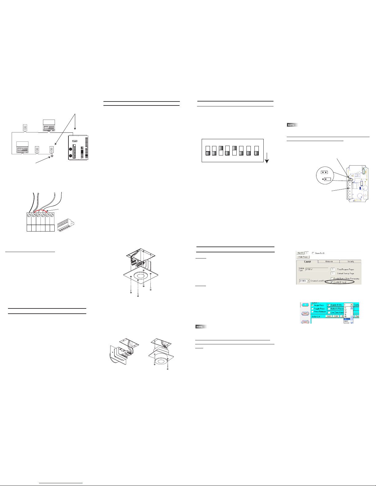
Wire the Phoenix/Luma-Net Connector
1. Connect leads per wiring diagram as illustrated on page
6.
2. Twist strands of each lead tightly (making sure that
there are no stray strands) and push firmly into appropriate plug connector location.
3. Tighten the screws on the plug connector-making sure
that no bare conductor is showing.
4. Tie the Drain/Shield wires together and insulate using a
small piece of heat shrink tubing.
5. Install termination jumpers as required. Remember a
termination jumper is required at the two ends of the
Luma-Net® run.
REM+
REM -
COM
TERM
LOCK
+V
1
2
345
6
Up to 1 #12AWG
2#12AWG
2#12AWG
Up to 1 #12AWG
Drain/Shield - Insulated and tied together
(Ground at one point onlyprobably an end)
Red
(+V )
Black (Common)
5
6
1
2
3
4
Phoenix/Luma-Net Connecto
r
Luma-Net® Wire Connections
Ceiling Mount IR for
D4200 and D8000
Cat #
D42IR-RSW
D42IR-RFW
KIRRF-00W
KIRRS-00W
3 4
a-2000D
PRESET SELECT STATION
17
16
18
10
11
14
13
15
12
5
8
7
9
6
B
2
4
3
C
1
A
D4200 CONTROL STATION
LUMANET
DMX
CLEAR
CANCEL
FAN
COMMUNICATION PORTS
FULL BRIGHT
AUXILIARY
PHASE LOSS
BRIGHT
SELECT
FULL
SAVE
LUMA-NET III HUB
a-2000D
PRESET SELECT STATION
17
16
18
10
11
14
13
15
12
5
8
7
9
6
B
2
4
3
C
1
A
D4200 CONTROL STATION
LUMANET
DMX
CLEAR
CANCEL
FAN
COMMUNICATION PORTS
FULL BRIGHT
AUXILIARY
PHASE LOSS
BRIGHT
SELECT
FULL
SAVE
LIT-32686-000
Rev A 3/2004
Page 2
Stations need to be given an unique address between
1 and 127. If a station address is set to Zero it will not
participate on the network. You use the address
switch to set both the association to the master station
as well as the IR stations unique address.
The switch is set to the binary representation of the ID
number. The binary 1’s column is left-most (lever
labeled “1”).
The switch levers are numbered 1-8, these represent
the following:
Lever=Value
1=1 2=2
3=4 4=8
5=16 6=32
7=64 8= Not Used
Add the value of each lever in the “ON” position to
determine the ID number (decimal form).
For example:
To set the address to 39, the following switches need
to be in the “ON” position:
1, 2,3,6 = 1+2+4+32=39
Station Addressing
D4200 CONTROL STATION
PRESET SELECT STATION
C
12
18
15
16
17
13
14
6
9
10
11
7
8
3
4
5
1
2
A
B
DMX
CANCEL
LUMANET
CLEAR
PHASE LOSS
AUXILIARY
FULL BRIGHT
COMMUNICATION PORTS
FAN
SAVE
FULL
SELECT
BRIGHT
A2000-D
Ground Shield
at one point only!
Terminate LumaNet in
these locations
Luma-Net® Termination Jumper
Locations
REM+
REM -
COM
TERM
LOCK
+V
1
2
345
6
Termination Jumper
5
6
1
2
3
4
Phoenix/Luma-Ne
t
Connector
Testing the Wiring
To assure problem-free start-up, it is important to check
the system wiring, prior to hooking up any control stations, for proper connections, shorts and opens.
The following procedure is recommended:
Step 1: Test the following wire pairs for shorts at each
station location, using an ohmmeter or other continuity
tester.
1-2 Open
2-3 Open
3-4 Open
Step 2: Repair any short circuits before continuing.
Step 3: Install wire jumpers, one pair at a time (not
supplied) to the Luma-Net Connector on either end of
the cable run between pins 1-2, then 2-3, then 3-4.
Step4: Retest each of the following wire pairs at each
connector:
1-2 Short
2-3 Short
3-4 Short
Step 5: Make any necessary repairs and remove wire
jumpers before continuing.
14
O N
1 2 3 4 5 6 7 8
O
F
F
1 + 2 + 4 + 8 + 16 + 32 +64 + 128
Net ID
(Line indicates the silkscreen below the dipswitch)
Installation
7
8 9
Figure: install of flush mount unit
Surface Mount Units:
1. Plug the Luma-Net connector into the back of the
surface mount unit as shown in the figure below.
2. Gently push the wire and assembly into the desired 1
gang electrical box.
3. Use the 2 6-32 screws provided to secure the unit to
the electrical box in the ceiling.
Figure: install of surface mount unit
You must associate the IR station with a Master Station,
either a D4200 LCD station or a D8000 station, in a similar fashion to the D4200 Entry Stations.
Multiple IR stations of various types can be
slaved to a single master station.
T
o set the remote identification number, and slave it
to a master D4200 or D8000 station:
1. With the station unplugged, set the IR station’s DIP
switches to the address of the master station that it is to
be slaved with.
2. Move the small programming jumper, adjacent to the
Luma-Net connector, so it is plugged onto both pins on
the circuit board.
3. Power up the station by plugging it back in. The red
LED above the jumper will stay lit until the programming
is complete (the D8000 version will flash 3 times).
4. Once the LED goes out, unplug the Luma-Net connector.
D4200:
There is no additional programming that needs to be
done. The D4200 LCD will respond to the hand held
IR units out of the box. If it does not work, double
check the D4200 LCD station to see if the IR port is
turned on. Refer to the units User Guide for details.
D8000:
The IR station is programmed to work out of the box
on a 1 for 1 line up of buttons. This works well for
most station types except the LCD. In this case, it is
recommended that you change the button mapping of
the IR station. You can either create the file in
LumaEdit or use the enclosed CD rom with the ldt file
for an IR station slaved to a generic LCD station.
Treat the IR station just like a 15 button entry station,
that has been slaved to another D8000 station.
In a D8000 system, the IR station does not
have to be slaved to another station
T
o specify a button to listen to a specific command
from a Hand Held remote other than default program
-
ming:
1. Open a 15 Button station in LumaEdit
2. Set the Network ID for the IR station.
3. Set the ID of the station it will be slaved to.
4. Click on the Enable IR button in the Station
Properties Section under Layout.
12 13
Setting the Address Con’t:
5. Remove the programming jumper and replace it so
that it is on only one pin.
6. With the station still unplugged, set the DIP switches
to the desired ID number for this particular remote station
(every station on the network must have its own unique
station number between 1-127).
7. Power up the station by plugging it back in, and it
should be ready to operate normally. When the station
first powers up under operating conditions, the back Red
LED flashes rapidly until the Luma-Net® network
becomes stable/operational.
Programming/Operation
10
2
5
U7
J2
1
N
O
1
28
6
4
321
6
842
1
S1
LEVITON M
FG. CO
.
A
L
L R
IG
H
T
S RESERV
ED
M
ADE IN THE U.S.A.
PCA-61418-0X
REV-
R14
C9
R
2
3
C 2002
C 2002
TP
1
+
+
+
+
+
+
+
ADDRESS
G
U2
V
R
R8
L1
C4
J4
C8
X1
C3
R7
U8 EEPROM
R24
R25
R26
R
2
7
JP1
G
N
D
D
12
R29
IRO
C
FG
B
E
Q
1
D13
C
R30
O
SC
2
T
P
2
P
TB
7
P
TB
6
D7
Programming Jumper, "JP1"
Programming Position
Normal Operation
Luma-Net Connector
Flush Mount Units:
1. Plug the Luma-Net connector into the back of the
flush mount unit as shown in the figure.
2. Gently push the wire aside and install the unit into the
desired 2 gang switch box.
3. Use the 4 6-32 screws provided to secure the unit to
the switch box.
11
1. Click on the button you wish to program. The button
properties box will open.
2. Click on the check box next to “Enable IR Button”
3. From the pull down box to the right, click on the number/name on the hand held remote that you want this
button to respond to.
4. Repeat Steps 1-3 for every button you wish to
respond to an IR input.
5. Once you have completed the rest of the programming, save the file and write the program to the IR station.
6. You are ready for normal operation.
 Loading...