

Page 1
Installing and
!
BC
Testing an
Outlet Branch
Circuit AFCI/GFCI
Please read this leaflet
completely before
getting started.
DI-000-AGRBF-02A
CAUTION
• To prevent severe shock or
electrocution always turn the power
OFF at the service panel before
working with wiring.
• Use this Outlet Branch Circuit AFCI/
GFCI with copper or copper-clad wire.
Do not use it with aluminum wire.
• Do not install this Outlet Branch
Circuit AFCI/GFCI on a circuit that
powers life support equipment
because if the AFCI/GFCI trips it will
shut down the equipment.
• For installation in damp or wet
locations, the GFCI receptacle must
be Listed and marked as Weather
Resistant (WR).
• Must be installed in accordance with
national and local electrical codes.
• This Outlet Branch Circuit AFCI/GFCI
must be installed as the first outlet in
the branch circuit.
1. What is a Outlet Branch Circuit
AFCI/GFCI?
An Outlet Branch Circuit AFCI/GFCI is different from
conventional receptacles. It is intended to provide protection
to branch circuit wiring, cord sets, and power-supply cords
connected to it against the unwanted affects of arcing, as
well as protect against ground faults. In the event of an arc
or ground fault, an AFCI/GFCI will trip and quickly stop the
flow of electricity to mitigate the effects of the arcing that
poses a fire risk, as well as providing protection against
serious injury.
Definition of an arcing and grounding fault:
An arcing fault is an unintentional arcing condition in a
circuit. Arcing occurs as a normal condition in some motors
or when a switch opens. An example of unintentional arcing
would be arcing that occurs due to severed power-supply
cord conductors. A ground fault will allow electricity to
deviate from it's normal safe path to reach the ground. A
defective appliance can cause a ground fault.
An Outlet Branch AFCI/GFCI does not protect against circuit
overloads, short-circuits or against shock hazards.
NOTE: Leviton’s AFCI/GFCI’s contain a lockout feature that
will prevent RESET if:
• There is no power being supplied to the AFCI/GFCI.
• The AFCI/GFCI is miswired due to reversal of the LINE
and LOAD leads.
• The AFCI/GFCI cannot pass its internal test, indicating
that it may not be able to provide protection in the event
of an arc or ground fault.
2. The AFCI/GFCI's features
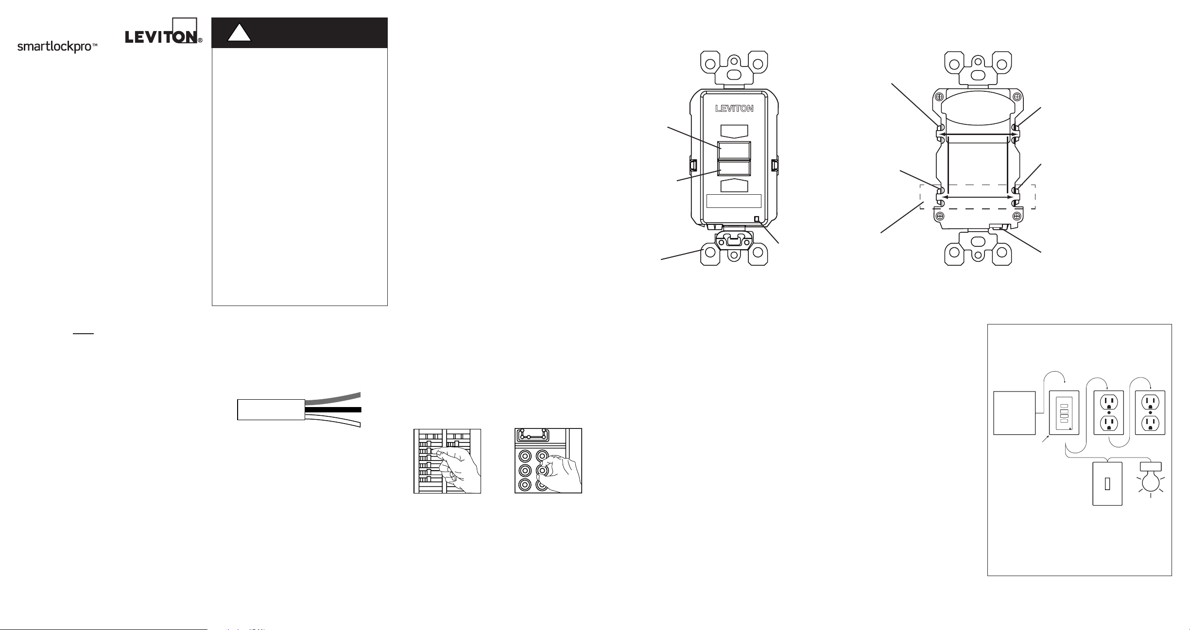
FRONT VIEW
RESET
button:
See step 8
TEST button:
See step 8
Mounting
Bracket
SWITCH
RESET
TEST MENSUEL
TEST MONTHLY
AFCI / GFCI
ON
TEST
OFF
FOLLOW INSTRUCTIONS
SUIVEZ INSTRUCTIONS
RESET
TEST
LED
Indicator
Light
LINE
Hot terminal
(Brass):
Connection for the
LINE cable's black wire
LOAD
Hot terminal
(Brass):
Connection for
the LOAD cable's
black wire
A yellow sticker covers
the LOAD terminals. Do
not remove the sticker at
this time.
BACK VIEW
LINE
HOT WIRE
LOAD
Screw (terminal) colors:
Green = grounding terminal
Silver = WHITE terminals
Brass or Black = HOT terminals
LINE
White terminal (Silver):
Connection for the LINE
cable's white wire
LOAD
WHITE WIRE
White terminal (Silver):
Connection for the LOAD
cable's white wire
Grounding Terminal (Green):
Connection for bare
copper or green wire
3. Should you install it?
Installing an Outlet Branch Circuit AFCI/GFCI
receptacle can be more complicated than
installing a conventional receptacle.
Make sure that you:
• Understand basic wiring principles and
techniques
• Can interpret wiring diagrams
• Have circuit wiring experience
•
Are prepared to take a few minutes to
test your work, making sure that you have
wired the
correctly
Outlet Branch Circuit AFCI/GFCI
4. LINE vs. LOAD
A cable consists of 2 or 3 wires.
Cable Wires
LINE cable:
Delivers power from the service panel (breaker
panel or fuse box) to the AFCI/GFCI. If there is
only one cable entering the electrical box, the
blank face AFCI/GFCI is not the correct device
for the application.
LOAD cable:
Delivers power from the AFCI/GFCI to
downstream receptacles in the circuit. This
cable should be connected to the AFCI/GFCI's
LOAD terminals only. The LOAD terminals are
under the yellow sticker. DO NOT remove the
sticker at this time.
5. Turn the power OFF
Plug an electrical device, such as a lamp or
radio, into the receptacle on which you are
working. Turn the lamp or radio ON. Then, go
to the service panel. Find the breaker or fuse
that protects that receptacle. Place the breaker
in the OFF position or completely remove the
fuse. The lamp or radio should turn OFF.
Next, plug in and turn ON the lamp or radio at
the receptacle's other outlet to make sure the
power is OFF at both outlets. If the power is not
OFF, stop work and call an electrician to
complete the installation.
6. Identify cables/wires
Important:
DO NOT install the Outlet Branch Circuit
AFCI/GFCI in an electrical box containing (a)
more than four (4) wires (not including the
grounding wires) or (b) cables with more than
two (2) wires (not including the grounding wire).
Contact a qualified electrician if either (a) or (b)
are true.
If you are replacing an old receptacle, pull it out
of the electrical box without disconnecting the
wires.
•
If you see one cable (2-3 wires), it is the
LINE cable. The receptacle is probably in
position C (see diagram to the right).
DO NOT install the AFCI/GFCI in this
position.
• If you see two cables (4-6 wires), the
receptacle is probably in position A or B
(see diagram to the right). Follow steps
a-e of the procedure to the right.
NOTE: The AFCI/GFCI must be installed in
position A.
Procedure: box with two (2) cables
(4-6 wires):
(a) Detach one cable's white wire and hot
wires from the receptacle and cap each
one separately with a wire connector.
Make sure that they are from the same
cable.
(b) Re-install the receptacle in the electrical
box, attach the faceplate, then turn the
power ON at the service panel.
(c) Determine if power is flowing to the
receptacle. If so, the capped wires are the
LOAD wires. If not, the capped wires are
the LINE wires.
(d) Turn the power OFF at the service panel,
label the LINE and LOAD wires, then
remove the receptacle.
(e) Go to step 7.
Placement in circuit:
The Outlet Branch Circuit Type AFCI/GFCI
must be placed as the first outlet in the
circuit.
A
LINE
Service
Panel
AFCI/GFCI
Sample circuit:
Always place an Outlet Branch Circuit
AFCI/GFCI in position A. All outlets of the
protected branch, including lighting and
receptacle outlets must be connected to the
load side of the AFCI/GFCI.
ON
OFF
LOAD
Page 2
White
7. Connect the wires only after reading other side completely
Wire
5/8" (1.6 cm)
Wire
3/4" (1.9 cm)
RESET
RESET
ON
OFF
TEST
TEST
RESET
RESET
ON
OFF
TEST
TEST
RESET
RESET
ON
OFF
TEST
TEST
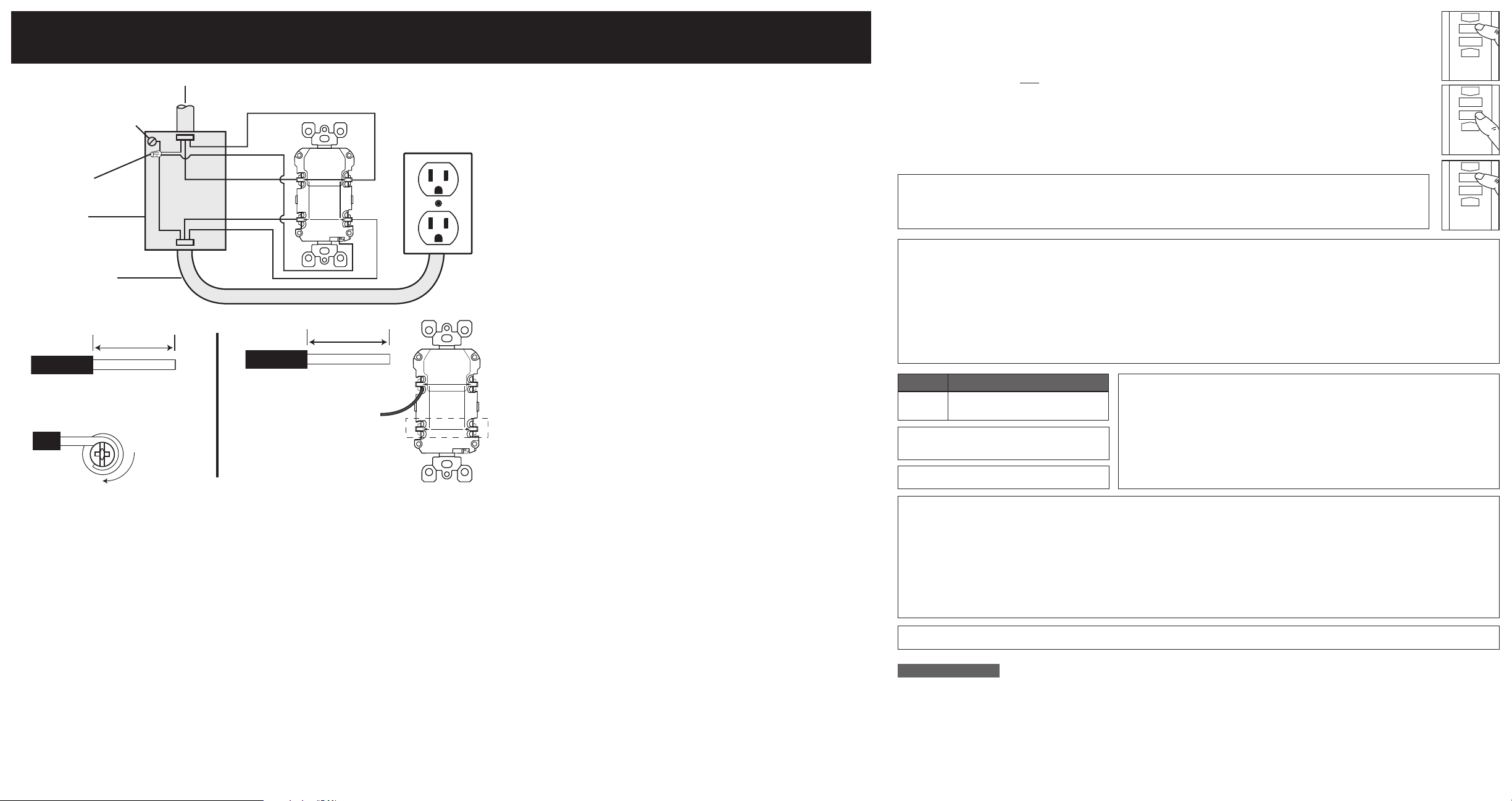
Two cables (4 or 6 wires) entering the box
Grounding connection
to box (if box has a
grounding terminal)
Wire
Connector
Electrical
Box
LOAD cable feeds
power to other
receptacle(s)
About Wire Connections:
Side Wire:
For Side wire -
Loop clockwise 2/3 of the
way around screw
LINE cable brings power to the AFCI/GFCI
Black
Black
White
FIL ACTIF
LIGNE
HOT WIRE
CHARGE
LINE
LOAD
FIL BLANC
WHITE WIRE
Back Wire:
For Back wire -
Insert bare wire fully and
tighten terminal clamp on
conductor ONLY
HOT WIRE
FIL ACTIF
CHARGE
LINE
LIGNE
LOAD
FIL BLANC
WHITE WIRE
Connect the LINE cable wires to the LINE terminals:
• The white wire connects to the WHITE terminal (Silver)
• The black wire connects to the HOT terminal (Brass or Black)
Connect the LOAD cable wires to the LOAD terminals:
• Remove the YELLOW sticker to reveal the LOAD terminals
• The white wire connects to the WHITE terminal (Silver)
• The black wire connects to the HOT terminal (Brass or Black)
Connect the grounding wires (only if there is a grounding wire):
•
Connect a 6-inch bare copper (or GREEN) 12 or 14 AWG wire to the
grounding terminal on the AFCI/GFCI. If the box has a grounding terminal,
also connect a similar wire to the grounding terminal on the box. Connect
the ends of these wires to the LINE or LOAD cable's bare copper (or
GREEN) wire using a wire connector. If these wires are already in place,
check the connections.
Complete the installation:
• Fold the wires into the box, keeping the grounding wire away from the
WHITE and HOT terminals. Screw the receptacle to the box and attach
the faceplate.
• Go to step 8.
8. Test your work - Why perform this test?
• If you miswired the AFCI/GFCI it may not prevent personal injury or death
due to a ground fault (electrical shock).
• If you mistakenly connect the LINE wires to the LOAD terminals, the AFCI/
GFCI will not reset and will not provide power to any receptacles fed from
the AFCI/GFCI.
Procedure:
(a) This AFCI/GFCI is shipped from the factory in the tripped condition and cannot be reset until it is wired correctly and power
is supplied to the device. Turn the power ON at the service panel. Ensure that the AFCI/GFCI is still in the tripped condition
by pressing the TEST button. If the indicator light on the AFCI/GFCI face is ON go to the Troubleshooting section because
LINE and LOAD wiring connections have been reversed. You will not be able to RESET the AFCI/GFCI in this condition.
(b) Press the RESET button fully. If the Indicator Light turns ON, the AFCI/GFCI has been installed correctly. If the AFCI/GFCI
cannot be reset, go to the Troubleshooting section.
(c) Press the TEST button, then plug a lamp or radio into surrounding receptacles to see which one(s), in addition to the AFCI/
GFCI lost power when you pressed the TEST button. DO NOT plug life saving devices into any of the receptacles that lost
power. Place a "AFCI/GFCI PROTECTED OUTLET" sticker on every receptacle that lost power, then press the RESET
button to reset the AFCI/GFCI.
(d) Press the TEST button (then RESET button) every month to assure proper operation. If the Indicator light does not go out
and come back on or if the AFCI/GFCI cannot be reset, then it must be replaced.
Turn the power OFF and check the wire connections against the wiring diagram in step 7. Make sure that there are no loose
wires or loose connections. If the Status Indicator Light is not ON and the device is unable to reset this could be a result of no
power available. Start the test from the beginning of step 8 if you rewired any connections to the AFCI/GFCI.
• This device tests itself periodically to confirm the GFCI electronics are functional. The Status Indicator Light will be solid GREEN when
the AFCI/GFCI is wired correctly, has power, is reset and working correctly.
• Self-Test Indications: If the Status Indicator Light is solid or a constant flashing RED a problem may exist. Press the TEST button to
trip the AFCI/GFCI. If unable to reset, replace the AFCI/GFCI.
NOTE: The status indicator may flash RED at power "ON" and RESET.
• GFCI Trip – if the AFCI/GFCI trips either from a ground fault or pressing of the TEST button the indicator will turn OFF.
• AFCI Trip – if the AFCI/GFCI trips as a result of detecting a potential arcing fault the indicator light will turn OFF similar to when it trips
due to a ground fault, but will also display two quick flashes of RED every five seconds. Press the RESET button to reset the AFCI/
GFCI. If the device trips and continues to indicate an AFCI trip please contact an electrician.
Cat. No. Description
AGRBF 20A-125 VAC, 60Hz,
SmartlockPro is a Trademark of Leviton Manufacturing
Co., Inc. registered in the United States, Canada, Mexico
and China.
For Technical Assistance Call: 1-800-824-3005 (U.S.A. Only)
FCC STATEMENT
This equipment has been tested and found to comply with the limits for a Class B digital device, pursuant to part 15 of the FCC Rules. These limits are designed to provide
reasonable protection against harmful interference in a residential installation. This equipment generates, uses and can radiate radio frequency energy and, if not installed and
used in accordance with the instructions, may cause harmful interference to radio communications. However, there is no guarantee that interference will not occur in a particular
installation. If this equipment does cause harmful interference to radio or television reception, which can be determined by turning the equipment off and on, the user is encouraged
to try to correct the interference by one or more of the following measures:
• Reorient or relocate the receiving antenna.
• Increase the separation between the equipment and receiver.
• Connect the equipment into an outlet on a circuit different from that to which the receiver is connected.
• Consult the dealer or an experienced radio/TV technician for help.
IC STATEMENT
This device complies with Industry Canada licence-exempt RSS standard(s). Operation is subject to the following two conditions: (1) this device may not cause interference, and (2)
this device must accept any interference, including interference that may cause undesired operation of the device.
Blank Face AFCI/Self Test GFCI
1 800 405-5320 (Canada Only) www.leviton.com
TROUBLESHOOTING
DEVICE OPERATION
Leviton warrants to the original consumer purchaser and not for the benefit of anyone else that this product at
the time of its sale by Leviton is free of defects in materials and workmanship under normal and proper use for
two years from the purchase date. Leviton’s only obligation is to correct such defects by repair or replacement,
at its option. For details visit www.leviton.com or call 1-800-824-3005. This warranty excludes and there is
disclaimed liability for labor for removal of this product or reinstallation. This warranty is void if this product is installed
improperly or in an improper environment, overloaded, misused, opened, abused, or altered in any manner, or is
not used under normal operating conditions or not in accordance with any labels or instructions. There are no
other or implied warranties of any kind, including merchantability and fitness for a particular purpose, but if
any implied warranty is required by the applicable jurisdiction, the duration of any such implied warranty, including
merchantability and fitness for a particular purpose, is limited to two years. Leviton is not liable for incidental,
indirect, special, or consequential damages, including without limitation, damage to, or loss of use of,
any equipment, lost sales or profits or delay or failure to perform this warranty obligation. The remedies
provided herein are the exclusive remedies under this warranty, whether based on contract, tort or otherwise.
LIMITED 2 YEAR WARRANTY AND EXCLUSIONS
This product is covered by U.S. Patents Nos. 6,040,967; 6,088,205; 6,282,070; 6,381,112; 6,433,978; 6,437,953; 6,639,769; 6,646,838; 6,657,834; 6,788,173; 6,944,001; 7,336,458; 7,400,479;
7,697,252; 7,907,371; 8,004,804; 8,054,595; 8,130,480; 8,599,522; 8,599,523; 8,944,859; 9,053,886 and corresponding foreign patents.
FOR CANADA ONLY
For warranty information and/or product returns, residents of Canada should contact Leviton in writing at Leviton Manufacturing of Canada Ltd to the attention of the Quality
Assurance Department, 165 Hymus Blvd, Pointe-Claire (Quebec), Canada H9R 1E9 or by telephone at 1 800 405-5320.
© 2017 Leviton Mfg. Co., Inc.
DI-000-AGRBF-02A
 Loading...