

Page 1
______________________________________
User Manual
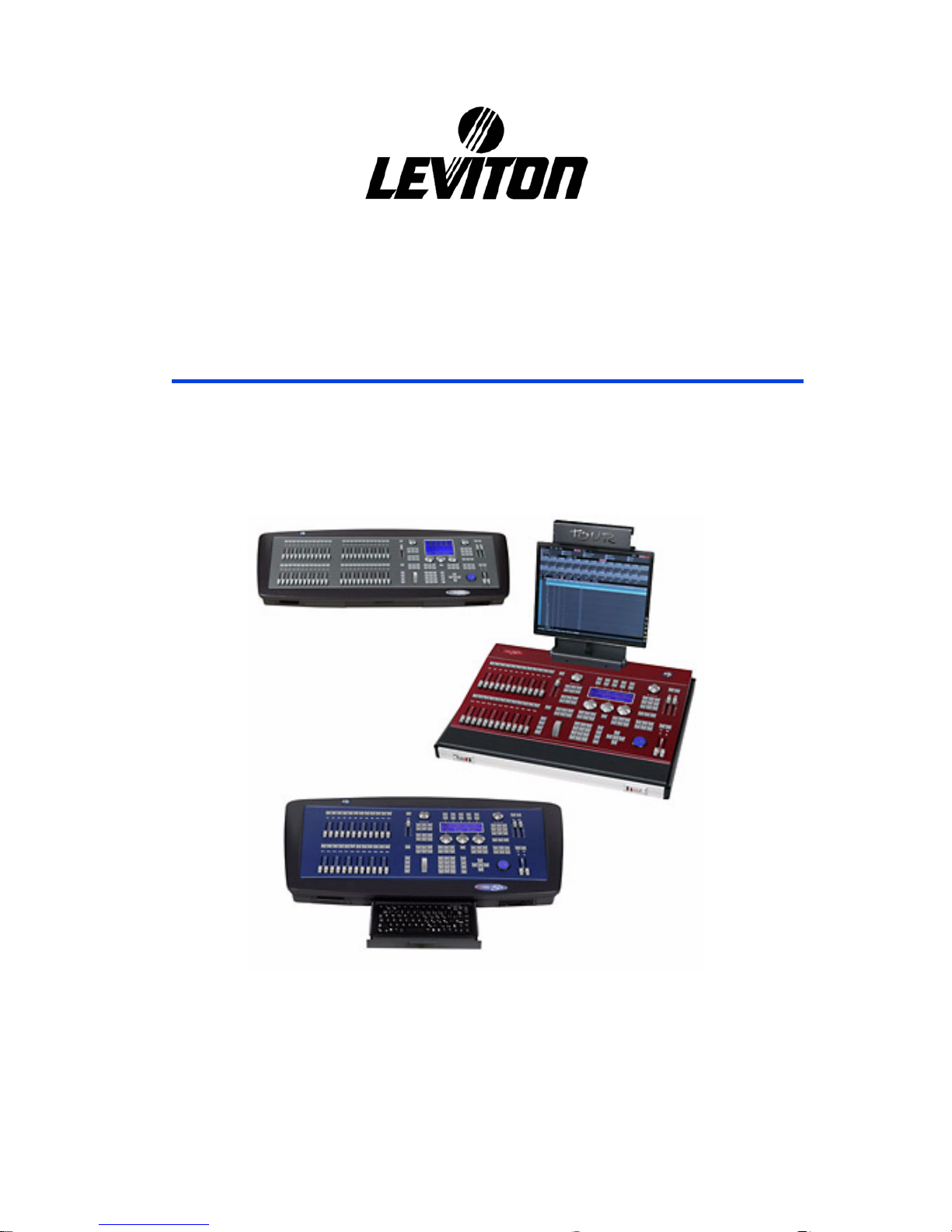
8700 Series
Document Release July 2007
Revision A
Page 2

Warranty
Leviton Manufacturing Co Inc. warrants this control console to be free of material and
workmanship defects for a period of two years after system acceptance or 26 months after
shipment, whichever comes first. This Warranty is limited to repair of replacement of
defective equipment returned Freight Pre-Paid to Leviton Lighting Management Systems
Division at PO Box 2210, Tualatin, Oregon 97062, USA. User shall call 1-800-959-6004 and
request a return authorization number to mark on the outside of the returning carton, to
assure that the returned material will be properly received at Leviton. All equipment shipped
back to Leviton must be carefully and properly packed to avoid shipping damage.
Replacements or repaired equipment will be returned to sender freight prepaid, F.O.B.
factory. Leviton is not responsible for removing or replacing equipment on the job site, and
will not honor charges for such work. Leviton will not be responsible for any loss of use time
or subsequent damages should any of the equipment fail during the warranty period, but
agrees only to repair or replace defective equipment returned to its plant in Tualatin, Oregon.
This Warranty is void on any product that has been improperly installed, overloaded, short
circuited, abused, or altered in any manner. Neither the seller nor Leviton shall be liable for
any injury, loss or damage, direct or consequential arising out of the use of or inability to use
the equipment. This Warranty does not cover lamps, ballasts, and other equipment which is
supplied or warranted directly to the user by their manufacturer. Leviton makes no warranty
as to the Fitness for Purpose or other implied Warranties.
Notice
Although the information contained within this user guide is believed to be accurate at the
time of printing, it is not guaranteed to be without fault and is subject to change without
notice. Future software releases may change the features or operation of this product. For
current information contact:
Leviton Lighting Management Systems Division
20497 SW Teton, Tualatin, OR 97062
Mailing Address:
PO Box 2210 Tualatin, OR 97062
Customer Service: (800) 736-6682
Technical Support: (800) 959-6004
Fax: (503) 404-5601
Internet:
www.lms.leviton.com
Copyright © 2007
Leviton Manufacturing Company Incorporated.
All Rights Reserved.
Page 3

1. 8700 SERIES INTRODUCTION AND CONNECTIONS ........................................... 1-1
1.1. 8700 SERIES........................................................................................................................................... 1-1
1.2. TECHNICAL CHARACTERISTICS.....................................................................................................1-2
1.2.1. GENERAL...............................................................................................................................1-2
1.2.2. MULTI-PROCESSOR SYSTEM............................................................................................1-4
1.2.3. ELECTRIC CHARACTERISTICS.........................................................................................1-4
1.2.4. AMBIENT...............................................................................................................................1-4
1.2.5. SIZE.........................................................................................................................................1-4
1.3. TECHNICAL SERVICE......................................................................................................................... 1-4
1.4. INSTALLATION & START UP............................................................................................................1-5
1.5. CONNECTIONS.....................................................................................................................................1-6
2. ABOUT THIS MANUAL.............................................................................................. 2-1
2.1. CONVENTIONS..................................................................................................................................... 2-1
2.1.1. OTHERS SYMBOLS..............................................................................................................2-2
2.2. BANKS KEYS........................................................................................................................................ 2-2
2.3. EDITION TABLES................................................................................................................................. 2-2
2.4. OPTIONS WINDOWS............................................................................................................................2-3
2.5. THE MOUSE.......................................................................................................................................... 2-3
3. SYSTEM CONFIGURATION...................................................................................... 3-1
3.1. THE MONITOR SCREENS...................................................................................................................3-2
3.2. MONITORS CONFIGURATION...........................................................................................................3-2
3.3. MOVING THE SCREENS ..................................................................................................................... 3-4
3.3.1. THE SCREENS BACKGROUND..........................................................................................3-5
3.4. HELP ON-LINE...................................................................................................................................... 3-5
3.5. INFORMATION ABOUT THE CURRENT SHOW..............................................................................3-5
3.6. @USER................................................................................................................................................... 3-5
4. FIXTURES PATCH...................................................................................................... 4-1
4.1. EDITING THE PATCH.......................................................................................................................... 4-2
4.2. LOADING A NEW FIXTURE DEFINITION........................................................................................4-4
4.2.1. THE FIXTURE DEFINITION INFORMATION ...................................................................4-6
5. EDITOR......................................................................................................................... 5-1
5.1 DEFAULT SELECTION.............................................................................................................................5-1
5.2 CHANNELS ................................................................................................................................................5-2
5.2.1 HTP & NO-TRACKING.........................................................................................................5-2
5.2.2 SELECTING CHANNELS .....................................................................................................5-2
5.2.3 EXCLUDING CHANNELS....................................................................................................5-3
5.2.4 EDITING CHANNELS...........................................................................................................5-3
5.2.5 SELECTING ALL THE ITEMS IN THE EDITOR................................................................5-4
5.2.6 INVERT FUNCTION..............................................................................................................5-4
5.2.7 OTHERS SELECTIONS.........................................................................................................5-5
5.2.8 RELEASING ITEMS OF THE EDITOR................................................................................5-5
5.3 FIXTURES................................................................................................................................................... 5-6
5.3.1 THE FIXTURES IN THE EDITOR........................................................................................5-6
5.3.2 LTP & TRACKING ................................................................................................................5-7
5.3.3 ABOUT THE FIXTURE PARAMETERS..............................................................................5-7
5.3.4 SELECTING FIXTURES........................................................................................................5-8
5.3.5 SELECTING AND EDITING PARAMETERS......................................................................5-8
5.3.6 EDITING A PARAMETER....................................................................................................5-9
5.3.7 NUMERIC EDITION..............................................................................................................5-9
5.3.8 EDITION IN THE CONTROL WHEELS ............................................................................5-11
5.3.9 WHEEL KEY........................................................................................................................5-11
5.3.10 FUNCTIONAL EDITION - PALETTES..............................................................................5-12
5.3.11 THE HOME VALUES..........................................................................................................5-14
0
Page 4

5.3.12
LIBRARIES ..........................................................................................................................5-15
5.3.13 THE PARAMETER OF CONTROL .................................................................................... 5-15
5.3.14 INVERT ................................................................................................................................5-15
5.3.15 RELEASING ITEMS OF THE EDITOR..............................................................................5-16
5.4 THE TRACKBALL................................................................................................................................... 5-17
5.5 THE STATUS LINE.................................................................................................................................. 5-19
RESUME.............................................................................................................................................................. 5-20
6. CUES & GROUPS ........................................................................................................6-1
6.1 STORING CUES & GROUPS .................................................................................................................... 6-1
6.1.1 CALLING TO THE EDITOR OF PLAYBACKS & DATA..................................................6-2
6.1.2 STORING THE SCENE IN THE NEXT CUE....................................................................... 6-4
6.1.3 EXAM OF CUES & GROUPS...............................................................................................6-4
6.1.4 ASSOCIATE A TEXT TO A CUE OR GROUP....................................................................6-5
6.1.5 DELETE CUES OR GROUPS................................................................................................6-5
6.1.6 MODIFY A CUE OR GROUP................................................................................................6-6
6.1.7 COPY CUES OR GROUPS....................................................................................................6-6
6.1.8 EXCHANGE CUES OR GROUPS......................................................................................... 6-7
6.2 CUE TIMES................................................................................................................................................. 6-8
6.2.1 PROGRAMMING TIMES FROM THE CUE LIST...............................................................6-9
6.3 TIMING..................................................................................................................................................... 6-10
6.3.1 SET THE DEFAULT TIMING.............................................................................................6-14
6.3.2 EDITION OF THE CUE TIMING........................................................................................6-14
6.3.3 CONVERT TIMINGS TO CUES PARTS............................................................................ 6-14
6.4 CUE PARTS.............................................................................................................................................. 6-15
6.4.1 EDITION OF PARTS ........................................................................................................... 6-15
6.4.2 RETURN A ITEM TO THE BASE CUE..............................................................................6-17
6.4.3 EDIT TIMES FOR THE CUE PARTS.................................................................................6-17
6.4.4 OTHERS ACTIONS WITH PARTS.....................................................................................6-17
6.5 MODIFY A RANGE OF CUES OR GROUPS......................................................................................... 6-18
6.5.1 The mode options (#1)........................................................................................................... 6-18
6.5.2 The attribute options (#2).......................................................................................................6-19
6.6 THE FIXTURES IN CUES & GROUPS...................................................................................................6-21
7. LIBRARIES....................................................................................................................7-1
7.1 POSITION LIBRARIES.............................................................................................................................. 7-1
7.2 DIM, COL, GOB, BEAM & X-TRA LIBRARIES..................................................................................... 7-2
7.3 COPY & EXCHANGE................................................................................................................................ 7-3
7.4 EXAM.......................................................................................................................................................... 7-3
7.5 DELETE....................................................................................................................................................... 7-4
7.6 EDITING WITH LIBRARIES.....................................................................................................................7-5
7.6.1 NUMERIC SELECTION........................................................................................................7-5
7.6.2 SELECTION IN CONTROL WHEELS ................................................................................. 7-5
7.6.3 SELECTION IN BANKS KEYS ............................................................................................7-6
8. MASTERS AND PAGES...............................................................................................8-1
8.1 MASTERS................................................................................................................................................... 8-1
8.1.1 LOADING GROUPS IN MASTERS......................................................................................8-1
8.1.2 LOADING CUES IN MASTERS...........................................................................................8-3
8.1.3 LOADING CHANNELS IN MASTERS................................................................................ 8-4
8.1.4 MODES................................................................................................................................... 8-5
8.1.5 MASTER IN MONITOR........................................................................................................8-5
8.1.6 EMPTYING MASTERS.........................................................................................................8-6
8.1.7 EXAMINING MASTERS.......................................................................................................8-7
8.2 MASTERS EDITION TABLE.................................................................................................................... 8-7
8.3 MASTERS IN SCENE ................................................................................................................................ 8-9
8.4 CONTROLLING A MASTER.................................................................................................................... 8-9
8.4.1 MANUAL CONTROL............................................................................................................ 8-9
1
Page 5

8.4.2
AUTOMATIC CONTROL....................................................................................................8-10
8.4.3 FLASH CONTROL...............................................................................................................8-11
8.5 MODIFICATION OF THE MASTERS CONTENTS...............................................................................8-11
8.6 THE MASTER OF MASTERS..................................................................................................................8-12
8.7 PAGES....................................................................................................................................................... 8-13
8.7.1 STORING OF A PAGE.........................................................................................................8-13
8.7.2 PAGE TEXT..........................................................................................................................8-13
8.7.3 PAGE EXAM........................................................................................................................8-13
8.7.4 LOADING OF A PAGE IN MASTERS...............................................................................8-14
8.7.5 ASSIGNING A PAGE IN THE CROSSFADER..................................................................8-14
8.7.6 SELECTING A PAGE IN MASTERS Y CROSSFADER ...................................................8-15
8.7.7 MODIFYING A PAGE.........................................................................................................8-15
8.7.8 COPING & EXCHANGING PAGES..................................................................................8-15
8.7.9 DELETING PAGES..............................................................................................................8-15
9. THE EFFECTS .............................................................................................................. 9-1
9.1 RECORDING A EFFECT........................................................................................................................... 9-4
9.2 MODIFYING A EFFECT............................................................................................................................ 9-6
9.3 MODIFYING THE EFFECT PARAMETERS............................................................................................9-6
9.4 EXAM OF EFFECTS .................................................................................................................................. 9-6
9.5 COPING EFFECTS ..................................................................................................................................... 9-7
9.6 EXCHANGING EFFECTS..........................................................................................................................9-7
9.7 DELETING EFFECTS.................................................................................................................................9-7
9.8 THE EFFECTS PLAYBACK...................................................................................................................... 9-8
9.8.1 LOADING A EFFECT............................................................................................................9-8
9.8.2 ACTIVATING A EFFECT .....................................................................................................9-9
9.9 LEARN TIME FUNCTION.......................................................................................................................9-11
9.10 FIXTURES & EFFECTS ......................................................................................................................9-12
9.10.1 TAKE PRIORITY WITH A ACTIVE EFFECT...................................................................9-13
10. SEQUENCES.......................................................................................................... 10-1
10.1 LOADING SEQUENCES..................................................................................................................... 10-1
10.1.1 IN THE X1/X2 CROSSFADER............................................................................................10-1
10.1.3 IN A MASTER, M#...............................................................................................................10-3
10.2 EMPTYING A SEQUENCE................................................................................................................. 10-3
10.3 EXECUTION ........................................................................................................................................ 10-4
10.3.1 MANUAL CONTROL..........................................................................................................10-4
10.3.2 AUTOMATIC CONTROL....................................................................................................10-4
10.3.3 PRIORITY CONTROL (MASTERS)...................................................................................10-7
10.4 CONFIGURATION OF THE CROSSFADERS................................................................................... 10-8
10.4.1 Dipless Crossfade ..................................................................................................................10-8
10.5 THE ORDER OF THE CUES............................................................................................................... 10-9
10.5.1 PROGRAMMED JUMP........................................................................................................10-9
10.5.2 END.JP FUNCTION.............................................................................................................10-9
10.5.3 MANUAL DISPLACEMENT.............................................................................................10-10
10.6 RATE CONTROL............................................................................................................................... 10-10
10.6.1 In crossfaders.......................................................................................................................10-10
10.6.2 In masters.............................................................................................................................10-11
10.7 LEVEL CONTROL............................................................................................................................. 10-11
10.8 THE COMMANDS AND THE CROSSFADERS.............................................................................. 10-11
10.9 MDFY MDFY FUNCTION................................................................................................................ 10-12
10.10 THE CROSSFADER OUTPUT.......................................................................................................... 10-13
10.11 LEARN TIME in CROSSFADER ...................................................................................................... 10-13
11. MACROS................................................................................................................ 11-1
11.1 EDITING A MACRO ........................................................................................................................... 11-1
11.2 MACRO MODIFICATION .................................................................................................................. 11-2
11.3 MACRO EXAM....................................................................................................................................11-2
2
Page 6

11.4
DELETE A MACRO ............................................................................................................................ 11-3
11.5 MACROS COPY .................................................................................................................................. 11-3
11.6 MACROS EXCHANGE ....................................................................................................................... 11-3
11.7 MACROS PLAYBACK........................................................................................................................ 11-4
11.7.1 FROM THE EDITOR............................................................................................................11-4
11.7.2 FROM THE BANKS KEYS................................................................................................. 11-4
11.7.3 AS COMMAND OF A CUE.................................................................................................11-5
11.7.4 FROM THE EVENTS LIST .................................................................................................11-6
11.8 EXAMPLES.......................................................................................................................................... 11-6
11.9 POWER-UP MACRO........................................................................................................................... 11-6
12. GENERAL FUNCTIONS........................................................................................12-1
12.1 SELECTION OF A RANGE................................................................................................................. 12-1
12.2 COPY AND EXCHANGE FUNCTIONS ............................................................................................ 12-1
12.3 RELEASE ............................................................................................................................................. 12-3
12.4 SELECT & CALL FUNCTIONS..........................................................................................................12-3
12.5 MDFY & EXAM FUNCTIONS ........................................................................................................... 12-5
12.6 SELECTION OF THE NEXT ITEM.................................................................................................... 12-7
12.7 TEST FUNCTIONS.............................................................................................................................. 12-8
12.8 RESCUE................................................................................................................................................ 12-9
13. SHAPES...................................................................................................................13-1
13.1 EDITING SHAPE FOR A SELECTION.............................................................................................. 13-1
13.2 ADDING A SHAPE TO A SELECTION............................................................................................. 13-4
13.3 THE SHAPE EDITOR - ADJUSTEMENTS........................................................................................ 13-4
13.3.1 Effect/Nm..............................................................................................................................13-5
13.3.2 Advanced parameters: Games...............................................................................................13-8
13.3.3 Selections...............................................................................................................................13-9
13.4 SHAPES & PLAYBACKS ................................................................................................................. 13-10
13.5 SHAPES LIBRARY............................................................................................................................ 13-11
13.5.1 STORING NEW SHAPES..................................................................................................13-11
13.5.2 MAINTENANCE OF THE SHAPES LIST........................................................................ 13-12
13.5.3 LOADING SHAPES FROM OTHERS SHOWS................................................................13-12
13.6 EXAMINING SHAPES IN GROUPS & CUES................................................................................. 13-13
14. MENUS....................................................................................................................14-1
14.1 GENERAL EDITION ........................................................................................................................... 14-2
14.2 MENU 10 – TO STORE/LOAD A SHOW........................................................................................... 14-2
14.2.1 STORE A NEW SHOW........................................................................................................ 14-3
14.2.2 OVERWRITE A SHOW....................................................................................................... 14-3
14.2.3 LOAD A SHOW ................................................................................................................... 14-3
14.2.4 LOAD SOME ITEMS OF A SHOW .................................................................................... 14-4
14.2.5 DELETE A SHOW ...............................................................................................................14-5
14.2.6 THE SHOW FILE FORMATS .............................................................................................14-5
14.2.7 SELECT THE FORMAT & ACTIVE DISK........................................................................14-5
14.2.8 UPDATE THE SHOWS DIRECTORY................................................................................ 14-6
14.2.9 ORGANIZE SHOWS IN FOLDERS.................................................................................... 14-6
14.2.10 FORMAT ATHE FLOPPY DISK....................................................................................14-8
14.2.11 8700 SERIES SHOWS COMPATIBILITY..................................................................... 14-8
14.3 MENU 11 – DATA PRINT................................................................................................................... 14-9
SETUP CONFIGURATION.............................................................................................................................. 14-11
14.3.1 30: EDITOR & TIMES ....................................................................................................... 14-11
14.3.2 31: PLAYBACKS...............................................................................................................14-11
14.3.3 32: SYSTEM.......................................................................................................................14-12
14.3.4 33: DMX OUTS UPDATES ............................................................................................... 14-12
14.3.5 34: SECURITY....................................................................................................................14-13
14.3.6 35: REMOTE.......................................................................................................................14-13
14.3.7 36: POWER-UP MACRO................................................................................................... 14-14
3
Page 7

14.4
TOUCH SCREEN CALIBRATION (GX Models)...........................................................................14-14
14.5 SPECIAL COMMANDS .................................................................................................................... 14-15
14.5.1 70: MULTIMEDIA PANEL................................................................................................14-15
14.5.2 71: STATUS & PLAYBACKS ZERO................................................................................14-15
14.5.3 79: TOOLS..........................................................................................................................14-16
14.6 TESTS .................................................................................................................................................14-19
14.6.1 80: INPUTS.........................................................................................................................14-19
14.6.2 81: OUTPUTS.....................................................................................................................14-19
14.6.3 82: VGA ..............................................................................................................................14-20
14.6.4 83: DMX-IN ........................................................................................................................14-20
14.6.5 84: DMX-OUT ....................................................................................................................14-20
14.6.6 85: MEMORY.....................................................................................................................14-20
14.6.7 86: MIDI..............................................................................................................................14-20
14.6.8 87: Rs232.............................................................................................................................14-21
14.6.10 89: 8700-Link..................................................................................................................14-21
14.6.11 90: DISK.........................................................................................................................14-21
14.7 ALPHANUMERIC KEYBOARD ......................................................................................................14-22
14.7.1 99: Enable/Disable...............................................................................................................14-22
15. CHANNELS PATCH............................................................................................. 15-1
15.1 CHANNELS LIST ................................................................................................................................ 15-2
15.1.1 EDITING CHANNELS.........................................................................................................15-2
15.1.2 THE +Edit WINDOW...........................................................................................................15-3
15.2 DIMMERS LIST................................................................................................................................... 15-4
15.2.1 EDITING...............................................................................................................................15-4
15.3 SELECTION OF LIST.......................................................................................................................... 15-5
15.4 PATCH TOOLS .................................................................................................................................... 15-6
15.5 USER CURVES .................................................................................................................................... 15-8
15.5.1 PRE-PROGRAMMED CURVES .........................................................................................15-8
15.5.2 USER CURVES ....................................................................................................................15-9
16. DMX IN................................................................................................................... 16-1
16.1 DMX INPUT TEST ..............................................................................................................................16-3
17. FIXTURES DEFINITION ...................................................................................... 17-1
17.1 THE FIXTURE DEFINITIONS............................................................................................................17-1
17.1.1 IDENTIFICATION DATA...................................................................................................17-1
17.1.2 PARAMETERS DEFINITION .............................................................................................17-2
17.1.3 STEPS DEFINITION IN A PARAMETER..........................................................................17-4
17.2 EXAM & TYPE EDITION................................................................................................................... 17-5
17.3 EDITING A NEW TYPE...................................................................................................................... 17-6
17.4 SAVE TO DISK....................................................................................................................................17-6
17.5 CONCEPTUAL.....................................................................................................................................17-7
17.6 THE TYPES FILES ..............................................................................................................................17-8
18. SERIAL PORTS...................................................................................................... 18-1
18.1 PORTS CONFIGURATION................................................................................................................. 18-2
18.2 DEVICES OF THE CACHE LIST........................................................................................................ 18-2
18.2.1 DEVICE EDITION................................................................................................................18-3
18.2.2 CREATE A NEW DEVICE..................................................................................................18-5
18.2.3 LOAD A LIBRARY DEVICE..............................................................................................18-5
18.2.4 SAVE A DEVICE .................................................................................................................18-5
18.2.5 THE DEVICE FILES............................................................................................................18-6
18.3 THE COMMANDS IN THE SHOW .................................................................................................... 18-6
19. MIDI........................................................................................................................ 19-1
19.1 THE MIDI MENU ................................................................................................................................ 19-1
19.1.1 SETUP LINE.........................................................................................................................19-2
4
Page 8

19.1.2
MIDI CHART........................................................................................................................19-3
19.2 EXAMPLES.......................................................................................................................................... 19-6
19.3 CONNECTING 2 8700 Series consoles................................................................................................ 19-7
19.3.1 START CONNECTION........................................................................................................19-7
19.3.2 END CONNECTION............................................................................................................19-8
20. SOUND & EXTERNAL TRIGGERS.....................................................................20-1
20.1 SETUP LINE......................................................................................................................................... 20-2
20.2 CONFIGURATION ZONE................................................................................................................... 20-2
21. TIME CODE & EVENT LIST ................................................................................21-1
21.1 SMPTE, MTC, CLOCK & INTERNAL............................................................................................... 21-1
21.2 SETUP LINE......................................................................................................................................... 21-2
21.3 EVENTS LIST ...................................................................................................................................... 21-3
21.3.1 EDITION OF THE EVENTS LIST.......................................................................................21-4
21.3.2 TC EDITION OR TC CAPTURE......................................................................................... 21-4
21.4 ACTIVATING THE EVENT LIST ...................................................................................................... 21-4
22. RESET & UPDATE.................................................................................................22-1
22.1 RESET................................................................................................................................................... 22-1
22.2 SOFTWARE UPDATE......................................................................................................................... 22-1
22.2.1 SOFTWARE UPDATE by FLOPPY DISK.......................................................................... 22-2
22.2.2 SOFTWARE UPDATE by ETHERNET...............................................................................22-2
22.2.3 SOFTWARE UPDATE by USB DISK.................................................................................22-3
23. OFF LINE EDITOR.................................................................................................23-1
23.1 PC.......................................................................................................................................................... 23-1
23.1.1 INSTALLATION..................................................................................................................23-1
23.1.2 USING THE OFF LINE EDITOR........................................................................................ 23-2
23.1.3 SOME EXCEPTIONS...........................................................................................................23-4
23.1.4 OLE & Ethernet..................................................................................................................... 23-5
23.1.5 OLE demo .............................................................................................................................23-5
24. ETHERNET.............................................................................................................24-1
24.1 ETHERNET CONNECTIONS ............................................................................................................. 24-1
24.2 CONFIGURE A NET ........................................................................................................................... 24-2
24.2.1 SELECTING THE WORKING NET.................................................................................... 24-2
24.2.2 ACTIVATE ETHERNET COMMUNICATION..................................................................24-3
24.2.3 START A NEW SESSION ...................................................................................................24-3
24.2.4 DMX CONFIGURATION....................................................................................................24-5
24.2.5 EXAMINATION OF THE NET........................................................................................... 24-6
24.2.6 WORKING IN MASTER & FULL SLAVE MODE............................................................ 24-6
24.3 EBOX CONVERTERS......................................................................................................................... 24-7
24.4 CAPTURE............................................................................................................................................. 24-8
5
Page 9

6
Page 10

7
Page 11
1. 8700 SERIES INTRODUCTION AND
CONNECTIONS
1.1. 8700 SERIES
The models of the 8700 Series cover a great range of necessities and have the same use
philosophy. The shows of all models are compatibles.
Dimmers / DMX-Out Masters
GX: 8748 GX 2048 / 4 48
8724 GX 2048 / 4 24
8724 GXT (Tour) 2048 / 4 24
GS: 8748 GS 1024 / 2 48
8724 GS 1024 / 2 24
8724 GST (Tour) 1024 / 2 24
GL: 8724 GL 512 / 1 24
8724 GLT (Tour) 512 / 1 24
Between the models 48 & 24 the unique difference is the master number. The models of 24
masters are more compacted & used in small spaces.
The difference between the models 24 & Tour is that the Tour models are assembled inside a
suitcase with an integrated LCD monitor. More compact consoles for use in reduced spaces and
for a frequent transport.
This console has been designed following the CE normative, on electromagnetic emission and electric security.
LEVITON 8700 SERIES
Page 12
1-2 8700 SERIES INTRODUCTION AND CONNECTIONS
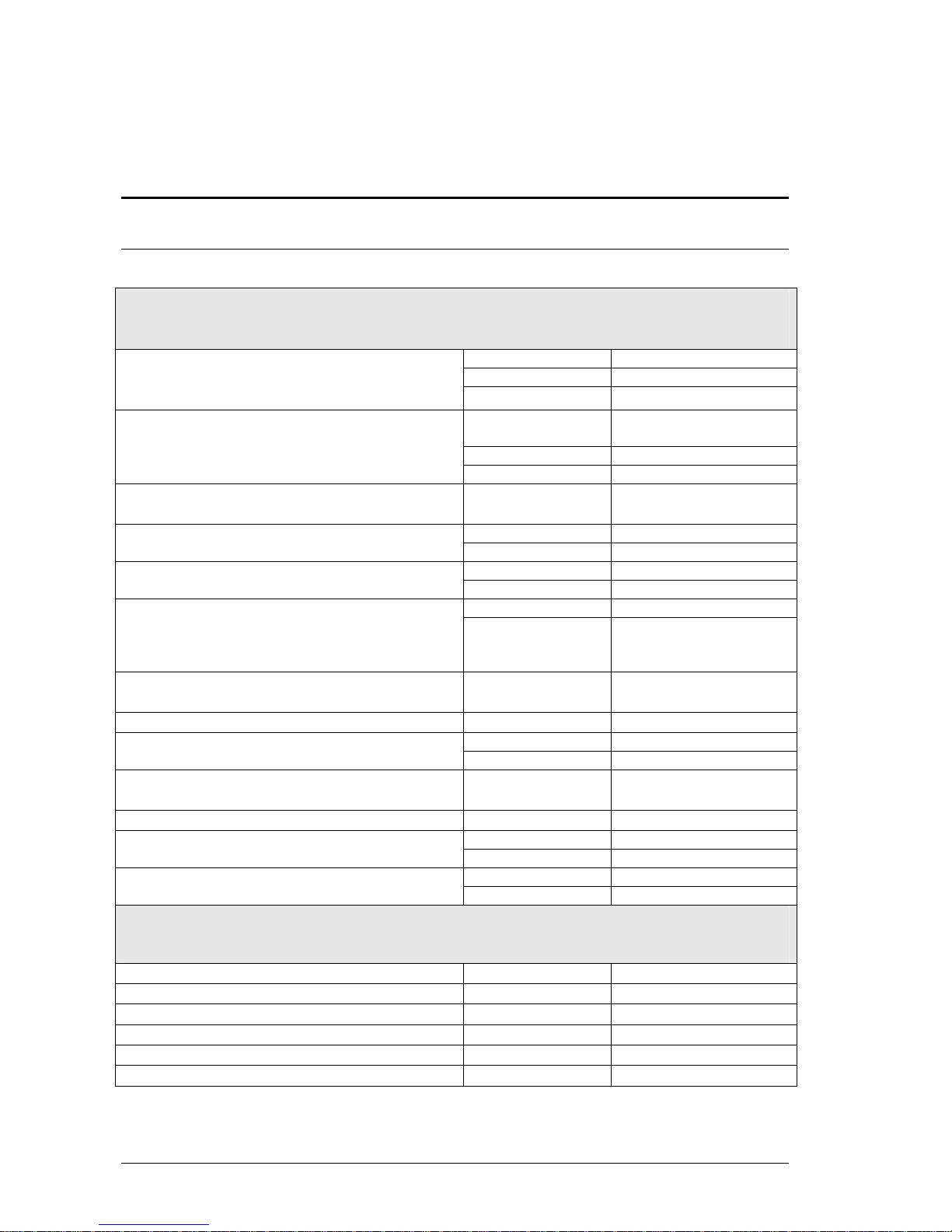
1.2. TECHNICAL CHARACTERISTICS
1.2.1. GENERAL
CAPACITY & INTERFACES
GX
2048
GS
1024
Control channels (maximum)
Configurable as conventional channels or
moving lights parameters.
GL
512
GX
4
GS
2
DMX Output
GL
1
DMX input channels to control channels,
moving lights, macros…
All models
512
Special Crossfaders
GX, GS, GL
1
Crossfader Submaster
GX, GS, GL
1 dedicated + programmable
8748GX, 8748GS
48
Masters with flash/assignation key.
To execute channels, groups, cues, effects &
sequences.
8724GL, 8724GX,
8724GS &
Tour models
24
Auxiliary Submaster, configurable as Masters
Control or DMX-IN Control.
All models
1
Grand Master & Black Out key
All models
1 (100% ó 200%)
Control of dimmer level
GX, GS, GL
Vertical Encoder
Track Ball (LED RGB illumination)
configurable to control position or mouse
All models
1
Encoders to control parameters, libraries, times..
All models
3
Auxiliary Encoders
GX, GS, GL
2
GX
240 x 320 Touch
DISPLAY
GS, GL
240 x 64
FUNCTIONALITY
Groups
All models
2000
Cues
All models
2000.9
Effects
All models
2000
Pages
All models
2000
Macros
All models
2000
Shapes (moving lights & conventional channels)
All models
Yes
LEVITON 8700 SERIES
Page 13
8700 SERIES INTRODUCTION AND CONNECTIONS
1-3
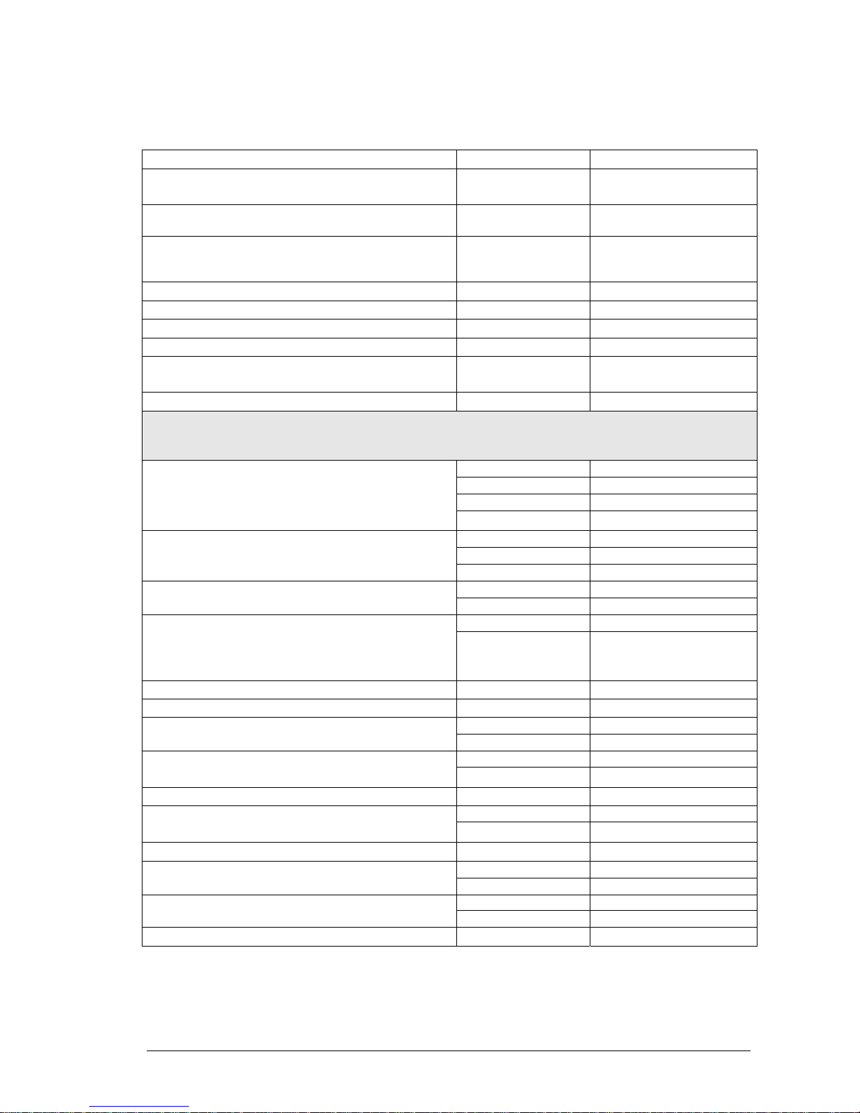
Palettes for edition
All models
Yes
Libraries for dimmer, position, color, gobo,
beam y Xtra
All models
99 per category
Special function for moving lights
All models
FLIP, FAN, FINE, IGNITE,
ORTO…
Moving lights configuration with libraries
grouped by manufactures.
All models
Yes
You can modify them &
program new libraries.
Dimmer Curves
All models
5 preprogrammed + 3 user
Timings
All models
6 preprogrammed (editable)
Capture (simulator software)
All models
Run on separate PC
Multimedia & events list
All models
Yes
Software upgrade using floppy, Ethernet or USB
memory.
All models
Yes
Compatible shows
All models
Yes
HARDWARE
GX
2 + 2 optional
GS
1 + 1 optional
VGA
For Tour models, the main monitor (LCD) is included
inside the suitcase, the rest are externals.
GL
1
GX
512M
GS
256M
HD (minimum)
GL
128M
GX, GS
Yes
Floppy Disk & internal keyboard
GL, Tour models
-
8748GX, 8748GS
2
Working light (littlite)
8724GL, 8724GX,
8748GS & all
Tour models
1
Ethernet
All models
10/100
USB
All models
2 ports
RS232
GX, GS, GL
1
All models
1 IN
SMPTE
MIDI
GX, GS, GL
IN-OUT
All models
1 IN
Audio
Printer
GX, GS, GL
Txt file
Externals
GX, GS, GL
3
All models
2 PS2
Mouse & Keyboard (externals)
LEVITON 8700 SERIES
Page 14

1-4 8700 SERIES INTRODUCTION AND CONNECTIONS
1.2.2. MULTI-PROCESSOR SYSTEM
Main microprocessor: GEODE SC2200 (266MHz).
Secondary microprocessor: H8/3003.
1.2.3. ELECTRIC CHARACTERISTICS
Main supply: 90-260V∼ / 50-60 Hz.
Intensity: 0.8A.
Category: II
1.2.4. AMBIENT
Temperature: -15ºC to 45ºC
Humidity: 80% without condensation.
1.2.5. SIZE
8748GX, 8748GS: 1155 x 442 x 70..130 mm, 22 Kg.
8724GX, 8724GS, 8724GL: 920 x 442 x 73..126 mm, 18.8 Kg.
8724GXT, 8724GST, 8724GLT: 675 x 530 x 155 mm. 21.5 Kg.
1.3. TECHNICAL SERVICE
Leviton Lighting Management Systems Division
20497 SW Teton, Tualatin, OR 97062
Mailing Address:
PO Box 2210
Tualatin, OR 97062
Customer Service: (800) 736-6682
Technical Support: (800) 959-6004
Fax: (503) 404-5601
Internet: www.lms.leviton.com
LEVITON 8700 SERIES
Page 15
8700 SERIES INTRODUCTION AND CONNECTIONS
1-5
1.4. INSTALLATION & START UP
• Unpack the console set. You will find: the 8700 SERIES console, the main cable, this user
manual, the control sheet and the guaranty sheet.
Note:
If any irregularity is observed in the package, due to transportation, (blows, humidity...) not
attempt to switch on the console and follows the process to solve this type of problems.
• Place the console in a plane surface.
• Connect the monitors to the VGA connectors (SUBD-15), with standard video cables. If
only 1 monitor is connected, connected it to the VGA-1 output. (for Tour models, monitor 1
is connected).
• Connect the DMX outputs.
• Connect the mains cable to IEC base of the console.
Tip:
Connect the console to a SAI to avoid main supply problems.
• Switch on the console (in the IEC base switch in the rear panel).
• After some auto-test, the monitor shows us the stage page. The console is ready to work.
• Set the General Master, GMÚ, at 100% and the BLKOUT key disable (LED off).
• Read this user manual.
If these directions are not followed, no guarantee for the safety of the equipment is granted.
Note:
The shut down process maintains the power supply some seconds before total disconnection.
This is a normal process.
LEVITON 8700 SERIES
Page 16
1-6 8700 SERIES INTRODUCTION AND CONNECTIONS
1.5. CONNECTIONS
Main supply: IEC base for 90-260V∼ / 50-60 Hz. Always, used normalized cables (confirm the
ground plug).
The main supply is protected by 2 fuses of 5 A, type F.
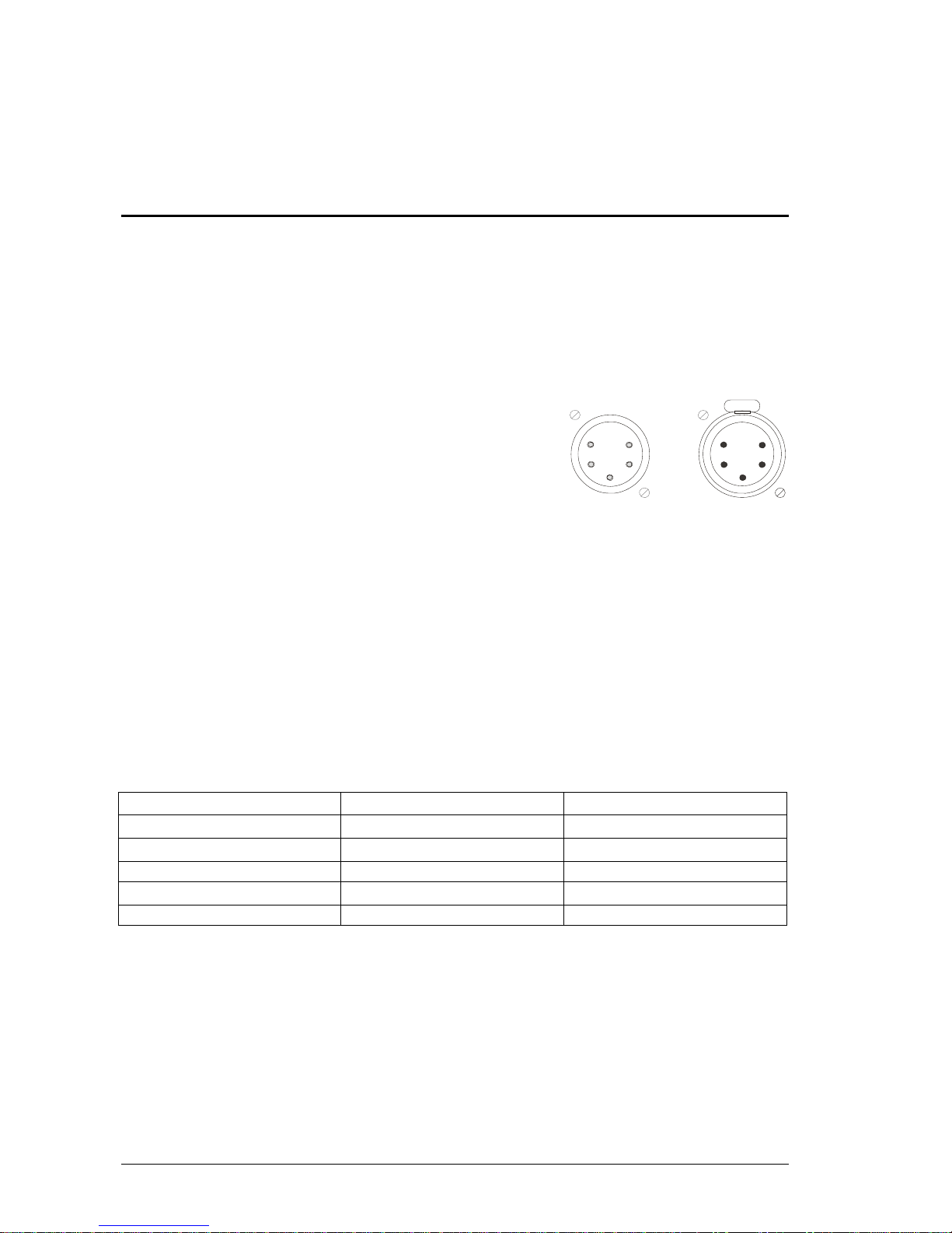
DMX:
4 Dmx-512 outputs with optical isolation. Connectors: Standard XLR-5 female.
1 Dmx-512 input with optical isolation. Connector: Standard XLR-5 male.
Code:
PUSH
Pin 1 : Ground.
Pin 2 : Data –
Pin 3 : Data +
Pin 4&5 : NC.
Always use shielded and twisted pairs cables, with 120 ohms of characteristic impedance and low
capacitance. Don’t use audio cables. The Data- & Data + signal have to be in the same twisted
pair.
Tip:
Connect 32 loads maximum in a one DMX line.
Use cables with maximum long of 100 metres.
Use the 120 ohms terminal load, between the pins 2 & 3 of the last DMX THRU connector.
Use DMX Splitters to connect more DMX loads or large cables.
Note:
The 8700 Series DMX signal is defined with these Parameters:
PARAMETER
8700 Series medium values
DMX512-1990 NORMA
Break Length
95 μs Minimum 88 μs
MAB Length
25 μs Minimum 8μs
Bytes/packet 512 channels 1-512 channels
Break to break
25.000 μs 170μs – 3.000.000μs
Updates/s 40 1-44
Audio input:
Stereo jack for 1Vpp audio signals. The signal is computed like mono signal. Code:
1 – 0 V ref. {jack body}
2 – N.C.
3 – Signal (1Vpp) {jack live point}
LEVITON 8700 SERIES
Page 17

8700 SERIES INTRODUCTION AND CONNECTIONS
1-7
SMPTE input
Stereo jack for 1Vpp SMPTE signals. The SMPTE input responds to the formats: 24, 25, 30 &
30 drop frame without adjusts. Code:
1 – 0 V ref. or SMPTE - {jack body}
2 – NC
3 – SMPTE + {jack live point}
External triggers.
GX, GS & GL:
XLR-4 (female) for 3 external triggers. Code:
1 – Ext-1
2 – Ext-2
3 – Ext-3
4 – 0 V ref.
Work Lights.
XLR-3 plastic connectors for 12V-15V/5w lamps. The work light is dimmed by the System.
Code:
Pin 1: 0 Vdc
Pin 2: 12 Vdc
Pin 3: 0 Vdc
LEVITON 8700 SERIES
Page 18

1-8 8700 SERIES INTRODUCTION AND CONNECTIONS
Reset Pushbutton (RST)
If by some circumstance your console did not switch off, it must be pushed this button to force a
disconnection of the battery.
PC standard ports:
RS-232 ports
VGA outputs - standard & TFT monitors.
KDB - alphanumeric keyboard.
MOUSE
MIDI
ETHERNET
2 USB
NOTE:
ALWAYS CONNECT THE MOUSE OR THE EXTERNAL KEYBOARD WITH THE
CONSOLE TURNED OFF.
LEVITON 8700 SERIES
Page 19
2. ABOUT THIS MANUAL
2.1. CONVENTIONS
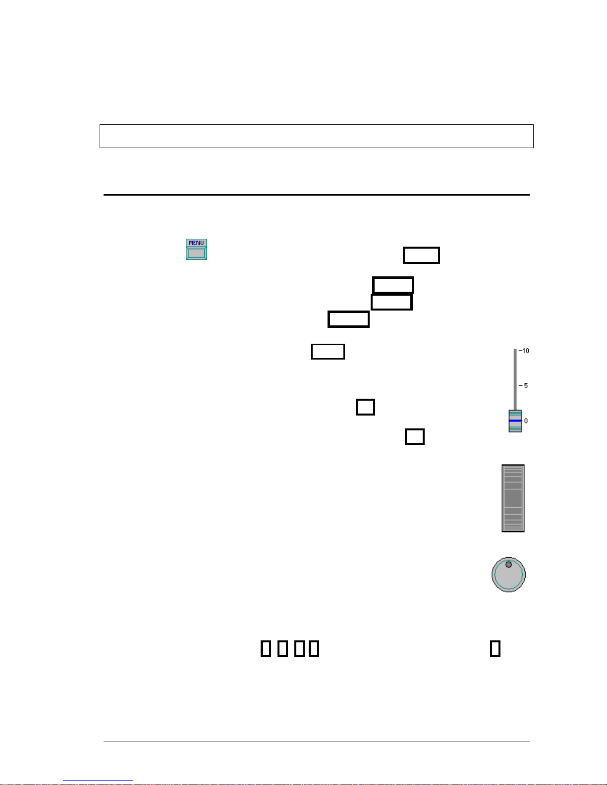
Concepts and general functions are written as: X1/X2, BANKS,…
Console models are written as 8748GX.
The physical keys, , are identified by its name and are written as MENU
A click (press & release) of a key is written as the key: ENTER
The pressing of a key (without releasing) is written as ENTER
The releasing of a pressed key us written as ENTER
The soft keys of the touch panel are written as: 1:Text
The master faders are identified by its name, and written as M1Ú
The master keys are identified by its name, and written as M1
To name “any” master fader or key, a general name is used: M#Ú or M3
Vertical encoder to control dimmer level, is written as: LevelÚ
The Trackball is written as TB
The parameters control encoders are written as W1, W2 y W3
The rotation of the encoders as: W1, W2 y W3
The pressing over the central zone of a encoder as: W1, W2 y W3
Rest of encoders are written with its name, as MONITOR or BANKS
The numerical data are written as: 0, 9 , 8 8, etc. A generic number is written as #. The
numeric data are entered using the numeric keyboard of the console.
LEVITON 8700 SERIES
Page 20
2-2 ABOUT THIS MANUAL
The flags of the status line and text of the command line are written as: 8748GX
The menu functions, and the editon cells of the editon-tables, are named with its names and
written as: Jump
A mouse click over an edition zone is written as: Edition_Zone
2.1.1. OTHERS SYMBOLS
/Notes, warning messages, L tips, and examples.
2.2. BANKS KEYS
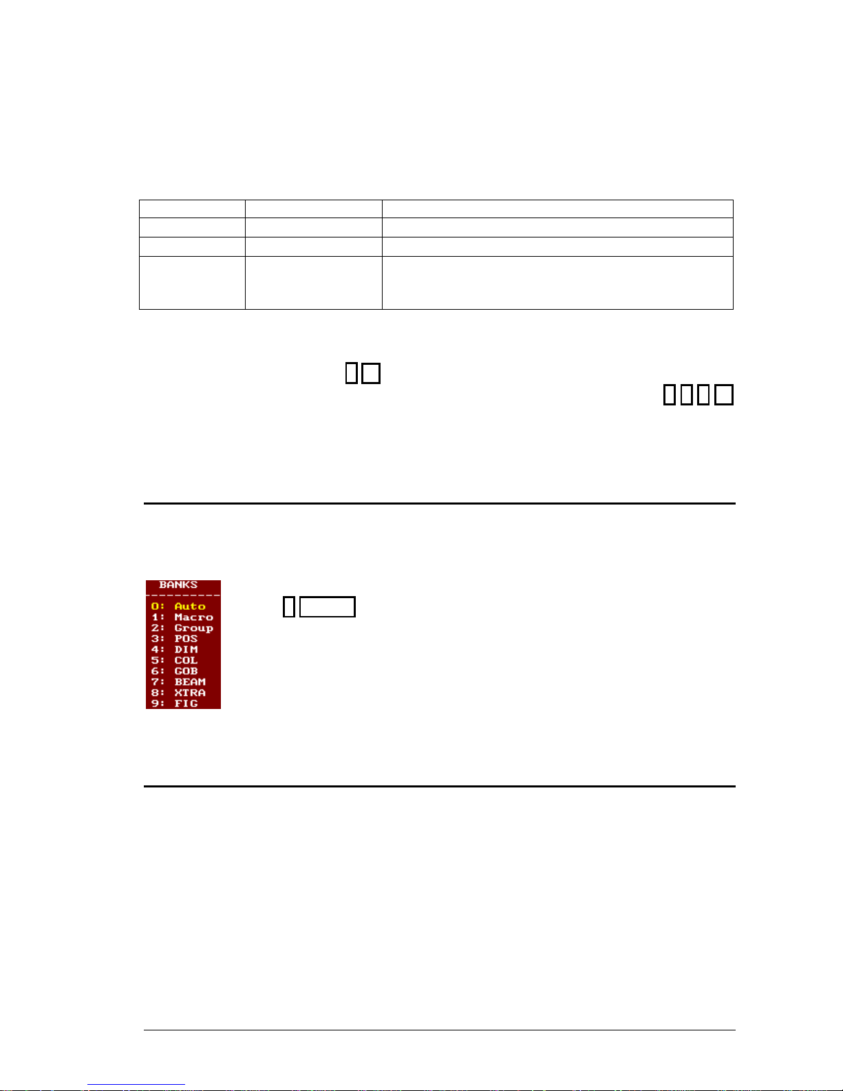
The console has 10 programmable-numeric keys, the BANKS, numbered from 1 to 10.
To avoid confusions, these keys are written as 1B, 2B
B
B , 3
B
, etc. To name “any” of them, a B
general name is used: #
B
For GX models, these keys are placed in the touch screen, and they are written as 1B,
2B, 3B, etc. To name “any” of them, a general name is used: #
B
BANKS allow you to access to macros, groups, positions, colors, etc. They are configured from
the BANKS encoder, and their contents are paged turning this same encoder: BANKS
2.3. EDITION TABLES
Some editions and menus are done in tables that the user can modify.
General:
The line that has the active cell is showed in a yellow field.
The active cell is in a red filed. When this active cell is been edited is in a light red field.
In the edition tables, select the cell for edition:
A. Using the arrow keys to move the cursor, Æ , Å , Ç &
B. Using the mouse, clicking in the desired cell, Jump
The edited data are accepted moving the cursor or pressing ENTER
The edition tables are closed pressing EXIT.
LEVITON 8700 SERIES
Page 21
ABOUT THIS MANUAL 2-3
The edition of the active cell depends of the cell type:
Cell type Example Edition
Numeric
Dmx, T
Using the console numeric keyboard
Text
Text, Title
Using the alphanumeric keyboard (internal or external)
Options
Command
Entered the index number of the desired option or
clicking over this option with the mouse. (see
following)
Most of tables have a column, in a gray field, in base to the one which are ordered. This column
can not be edited and is used for automatic displacement:
Over one of these cells, pressing # Æ , the cursor is placed over the line #.
Example for channels patch: If placed over the channel 3 (in a grey field), you press 1 2 8 Æ
the cursor jumps to the channel 128.
2.4. OPTIONS WINDOWS
During the edition process, in tables as well as in commands by keyboard, options windows can
be opened (always in a red field) to help you to complete the edition or command. These
windows present numbered options, and to select one of these options, as a rule, we can:
a) Press # ENTER to select the option #.
b) Select using the mouse the option #, #:Option
2.5. THE MOUSE
The external mouse can be used, with a simple click, to:
• Select any cell of the edition tables (cue list, patches, etc)
• Select a numeric option of the options red-windows (parameters, libraries, palettes, banks,
etc)
• Select the desired menu from the menus-list.
It’s possible to simulate the mouse using the console TB.
LEVITON 8700 SERIES
Page 22

2-4 ABOUT THIS MANUAL
To set the TB as muse, activate MOUSE, now the trackball is illuminated in green, indicating
that MOUSE mode is active. Move the pointer using the ball, and press MOUSE for the
“click”.
To deactivate the MOUSE mode of the TB and return to normal mode, press TB
LEVITON 8700 SERIES
Page 23
3. SYSTEM CONFIGURATION
GX
Max. Parameters: 2048
DMX outputs: 2048
GS
Max. Parameters: 1024
DMX outputs: 1024
GL
Max. Parameters: 512
DMX outputs: 512
The 8700 Series console is a configurable system. You can select the
number of masters, channels and fixture parameters.
Independently to the number of physical faders, the system can be
configured with 24 or 48 masters. Normally, the master number is the
same that the number the physical faders (except in connections masterslave).
The channels maximum is 2000, the parameters maximum varies
according to models (maximum 512 fixtures), and the maximum of
monitors, at present, is 2.
The total number of channels and fixture parameters used cannot be
greater than the number of DMX outputs.
8724GX: If the system is configured with 340 channels, the rest
(2048–340= 1708) will can be fixture parameters.
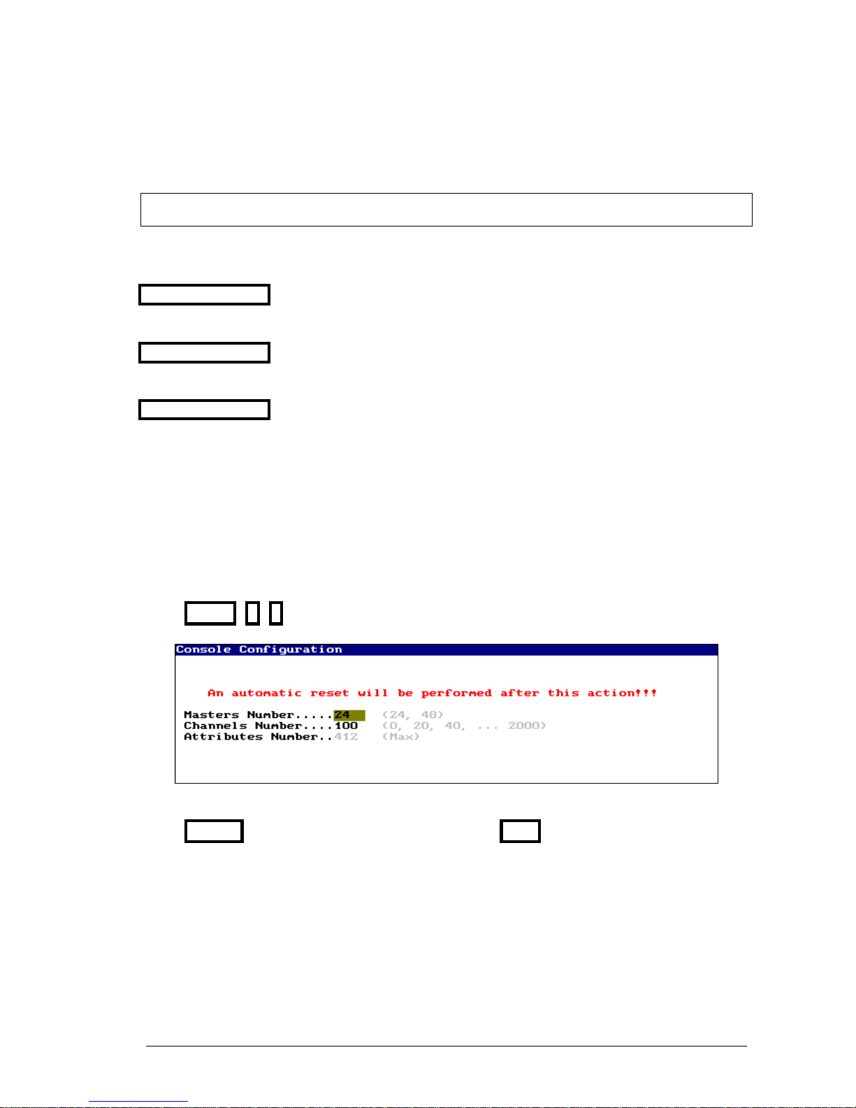
The system is configured in the menu 50: Console Configuration
MENU 5 0
To edit the configuration options, move the cursor to the desired option and enter the number.
Press ENTER to accept the entered data. To quit, press EXIT
If some option of CONSOLE CONFIGURATION is changed, the system is
Reseted, and the show is deleted. Store your show!
LEVITON 8700 SERIES
Page 24
3-2 SYSTEM CONFIGURATION
3.1. THE MONITOR SCREENS
In the monitors you can see:
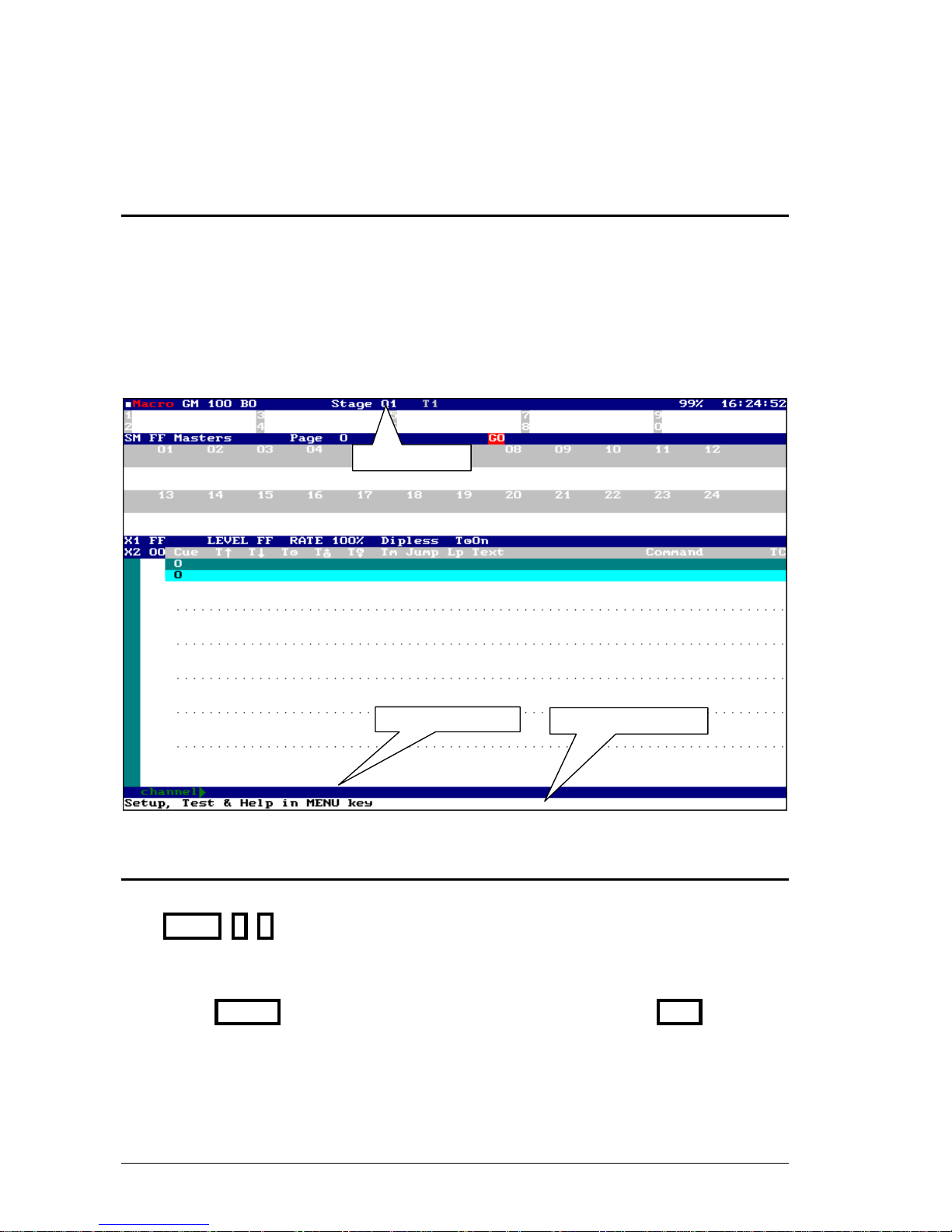
• Base screen, with information and status about playbacks.
• Auxiliary screens, with information and status about editors and scene.
All monitors and screen (base & auxiliary) have:
• Status line, for the general status of the system (blue area).
• Command line, for the action in process (blue area).
• Information line, for the show name and general messages (white area).
Status Line
Commands Line
Information Line
3.2. MONITORS CONFIGURATION
Monitors configuration is done from menu 60: Monitors Configuration:
MENU 6 0
The edition inside this menu is done following these steps:
• Move the cursor to the desired data, and enter the option number.
• Press ENTER to accept the entered data. To quit of this menu press EXIT
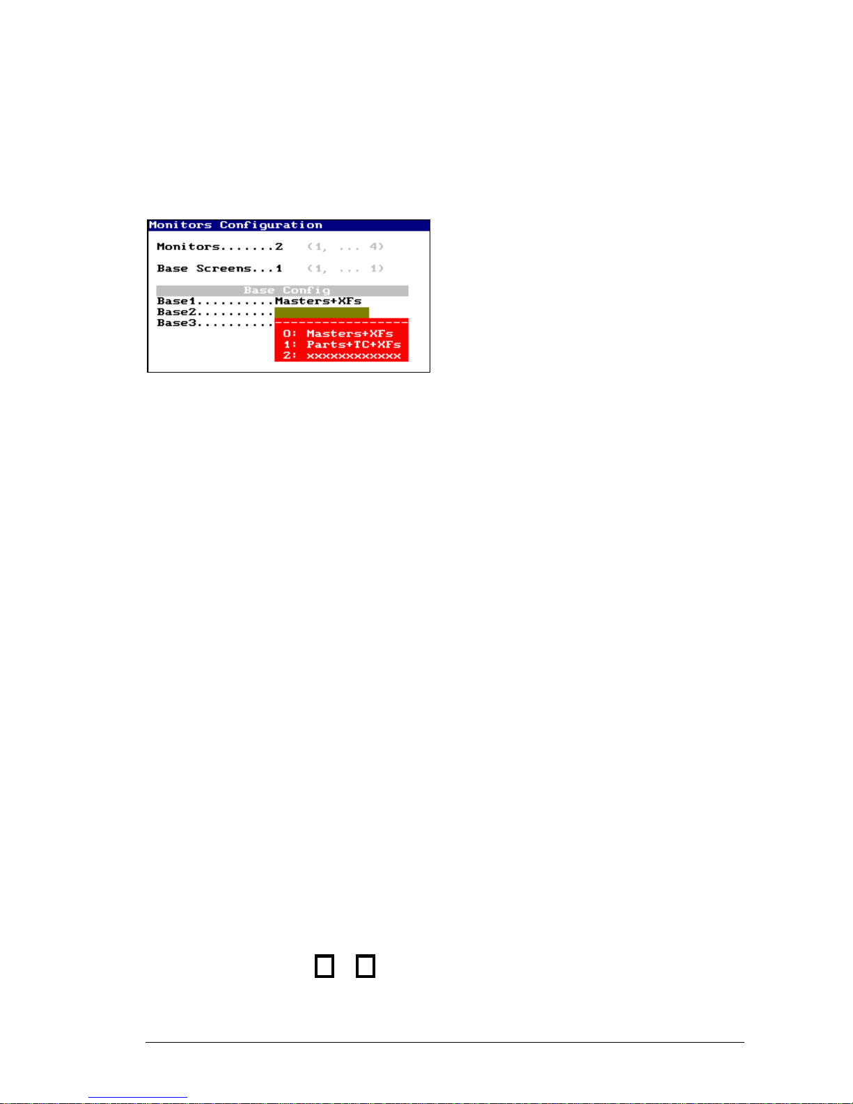
The first options, of this menu, are set the monitors number to use, set how many will be basescreens (the rest of the monitors will be for auxiliary screens), and set the formats of the basescreens.
LEVITON 8700 SERIES
Page 25
SYSTEM CONFIGURATION 3-3
The monitors’ number, Monitors, depends of the console hardware, and the model console, &
this number can be from 1 monitor to 4 monitors.
The system needs, minimum, 1 base screen,
Base Screens, and maximum, for
configuration of 1 or 2 monitors, 1 base screen;
for configurations of 3 monitors, 2 base screens;
and for configurations of 4 monitors, 3 base
screens.
Each base screen can be configured with the
following formats:
Option
Shown information
0: Masters+XFs
Information about masters and crossfaders
1: Parts+TC+XFs
Information about crossfaders and detail about the progress of
the parts in crossfade, plus, information about the events-list.
2: xxxxxxxxxxxxx
Yet not available
The format auxiliary screens depend of the number of channels and fixtures. The user can
personalize the order of visualization and behavior of these auxiliary screens.
The monitors’ number for auxiliary screens is calculated in accordance with the total number of
and the number of base screens configured:
Monitors -– Base Screen = Aux Screen
Only, when the system is working with 1 monitor, this monitor shows us the base screen and the
auxiliary screens.
The Aux Config options are:
ORDER: to select the visualization order for channels & fixtures, 1 is first place and 2 the last.
NEW PAGE: Option that permits us to force that the channels, or fixtures, begins in a new
screen (YES) or follows from the end of the previous item (NO).
Aux Fix: When the system has more than 1 monitor dedicated to auxiliary screens, in this cell,
you can select a number of monitors to fix them (without pagination).
If Auto Scroll option is ENABLED, the system jumps to the auxiliary screen, automatically, to
show us the last channel or fixture selected. If this option is DISABLED, the user must select
the desired screen pressing or
LEVITON 8700 SERIES
Page 26
3-4 SYSTEM CONFIGURATION
3.3. MOVING THE SCREENS
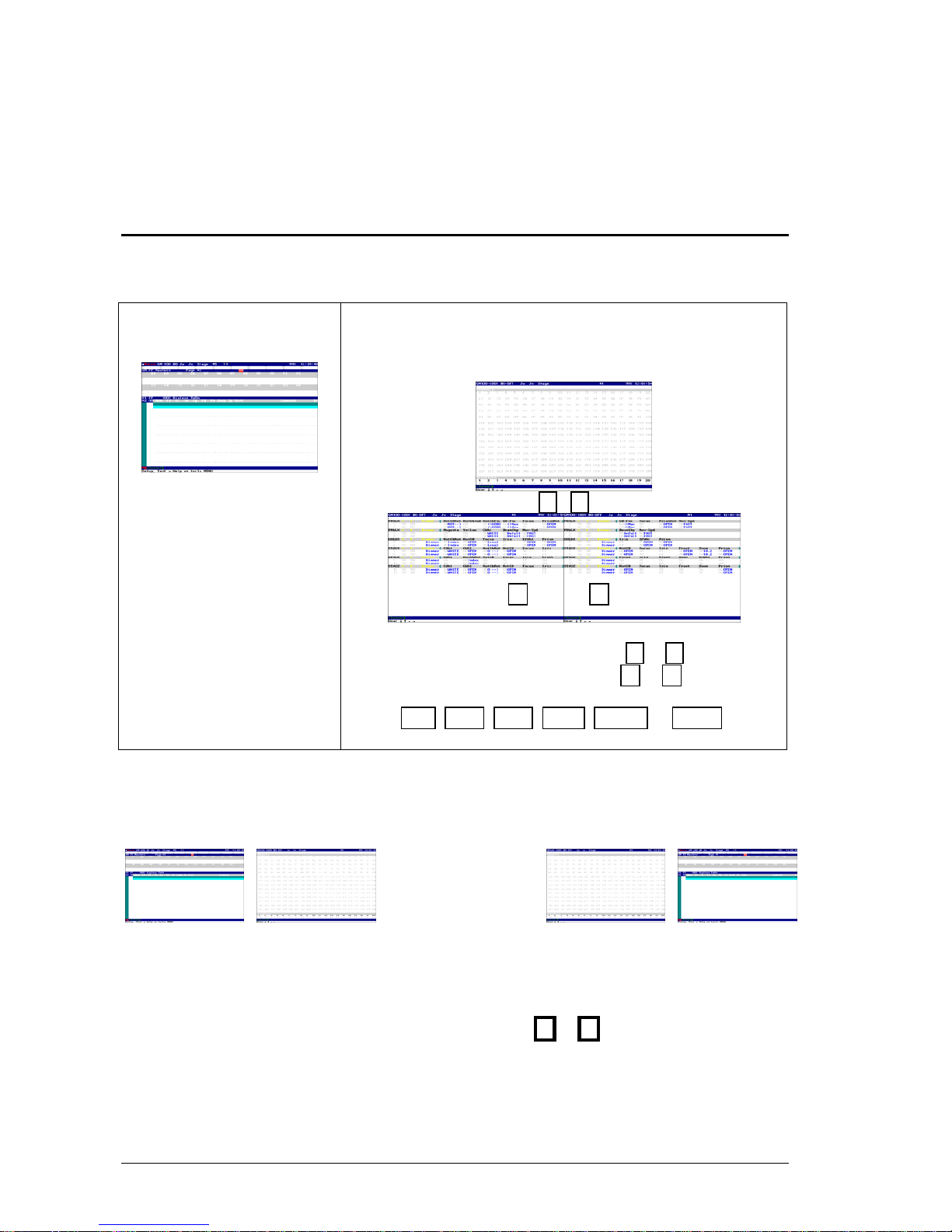
This process is in accordance with the monitors’ number and system configuration.
2 monitors, example:
MONITOR - 1
Base Screen
MONITOR - 2
Auxiliary Screens
(Fixed Screen)
To page this screens press &
To page the fixtures information press & , or select the
desired parameters type in the screen, pressing:
DIM, POS, COL, GOB, BEAM or XTRA.
At any moment, it’s possible to change the output of the base screen to the desired monitor
pressing MONITOR. This command allows you to place the base screen in the desired
monitor without to change the video cables.
MONITOR
1 monitor, example:
In this case, base screen and auxiliary screens are showed in the same phisical monitor, for this
reason, to select the desired screen (base or auxiliary) press: &
To page the fixtures information, the process is the same that for 2 monitors.
LEVITON 8700 SERIES
Page 27
SYSTEM CONFIGURATION 3-5
3.3.1. THE SCREENS BACKGROUND
The screens background can be configured in dark (gray) or light (white). To configure this
option, open the menu 32: System, and edit the MONITOR option:
If MONITOR is LIGHT (white), the screens appear in white background.
If MONITOR is DARK (gray), the screens appear in gray background.
3.4. HELP ON-LINE
The help pages are in the menu 69: Help, open this menu pressing:
MENU 6 9
This menu presents us an index with the help items. To open the help about one item, enter its
index number (with 2 digits) or scroll this pages pressing &
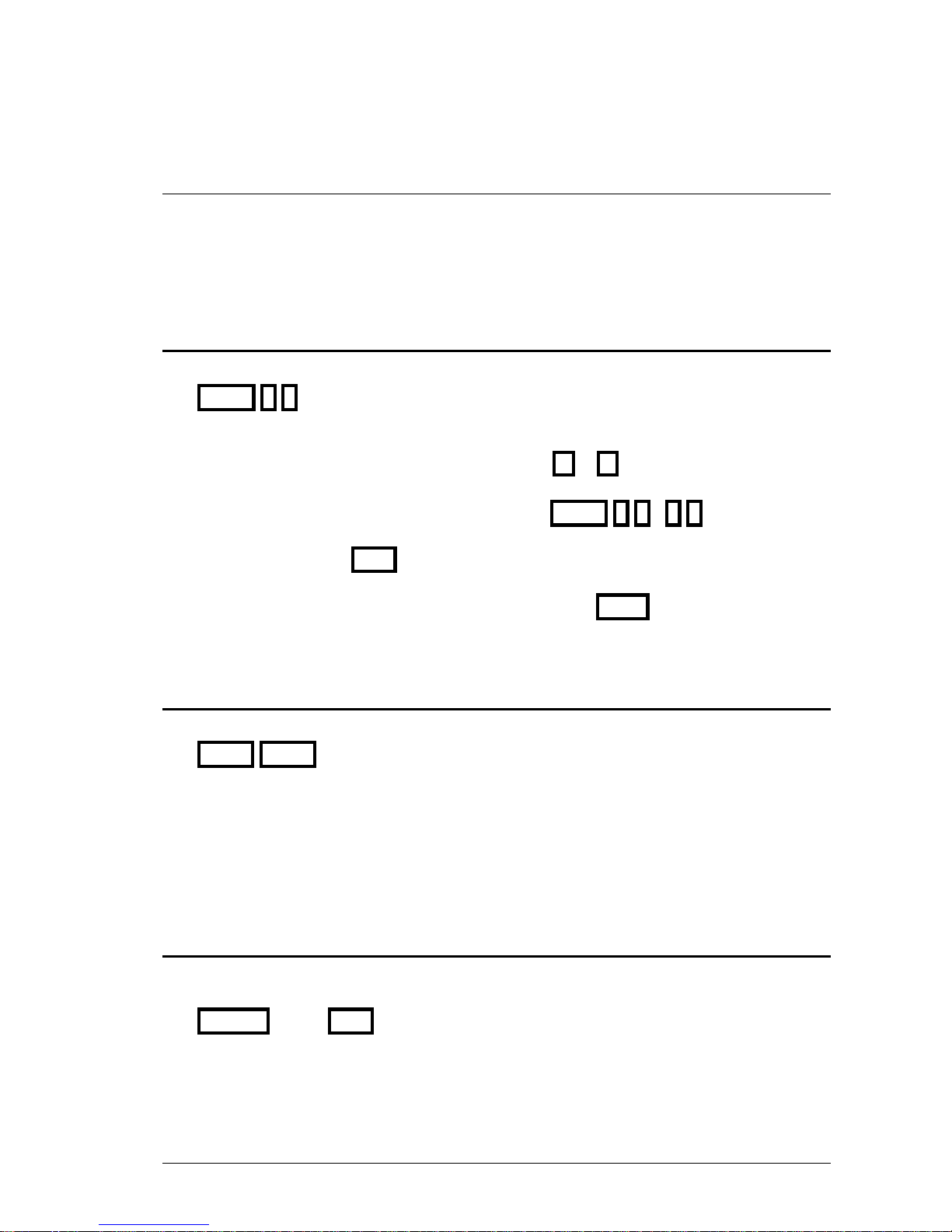
To consult the help-pages about the patches, press: MENU 6 9 0 9
Quit of this menu pressing EXIT
In other way you can request help about any function, pressing HELP and then, the function
key about the help is needed.
3.5. INFORMATION ABOUT THE CURRENT SHOW
There is a screen that presets us a resume about the current show data.
EXAM EXAM
In this screen you can see the number of the stored items (libraries, cues, groups, effects, pages,
macros…), the number of channels & fixtures used, and others.
When a new show is loaded from the disk, the system presents this general exam screen. Press
any key to close this general exam screen.
3.6. @USER
Allows us to access to a text page, in which you can write notes for the next working turn or
thing to remember…
@USER “text” EXIT
LEVITON 8700 SERIES
Page 28

3-6 SYSTEM CONFIGURATION
RESUME
System configuration:
In menu 50: Console Configuration: MENU 50
Screens and monitors configuration:
From menu Monitors Configuration: MENU 60
Paging screens:
In auxiliary screens: , , &
Search fixture parameters: DIM, POS, COL, GOB, BEAM, XTRA
Help on-line: MENU 69
HELP
Current show exam: EXAM EXAM
Text Messages: @USER “text” EXIT
LEVITON 8700 SERIES
Page 29
4. FIXTURES PATCH
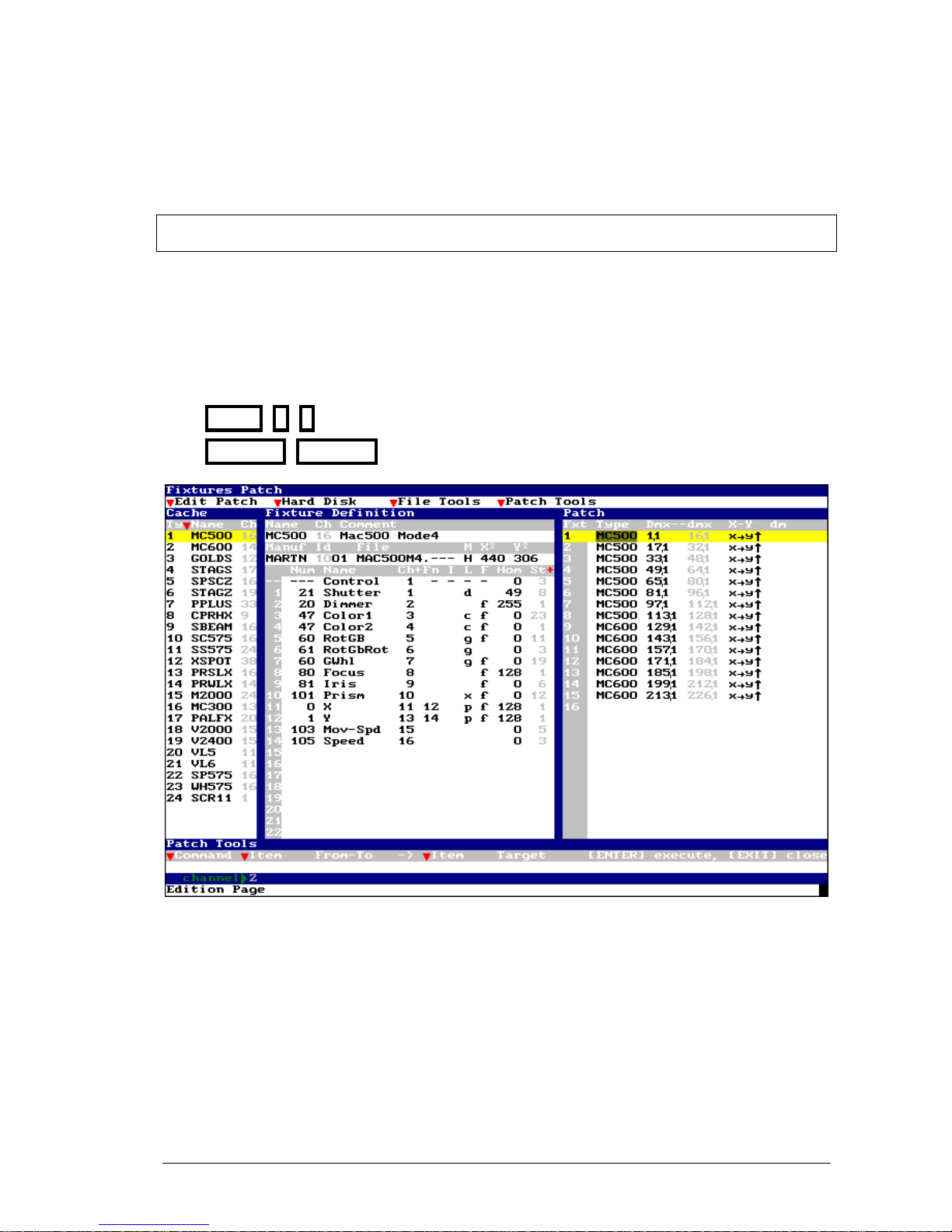
The Fixtures Patch permits us to configure the type and number the fixtures to control. This
configuration is a needed step to work with moving lights.
The maximum number of fixture to control is 512. In no case, the parameters number can be
highest that the number of attributes that appears in the menu 50: Console Configuration
The fixtures Patch is in the menu 04: Fixtures
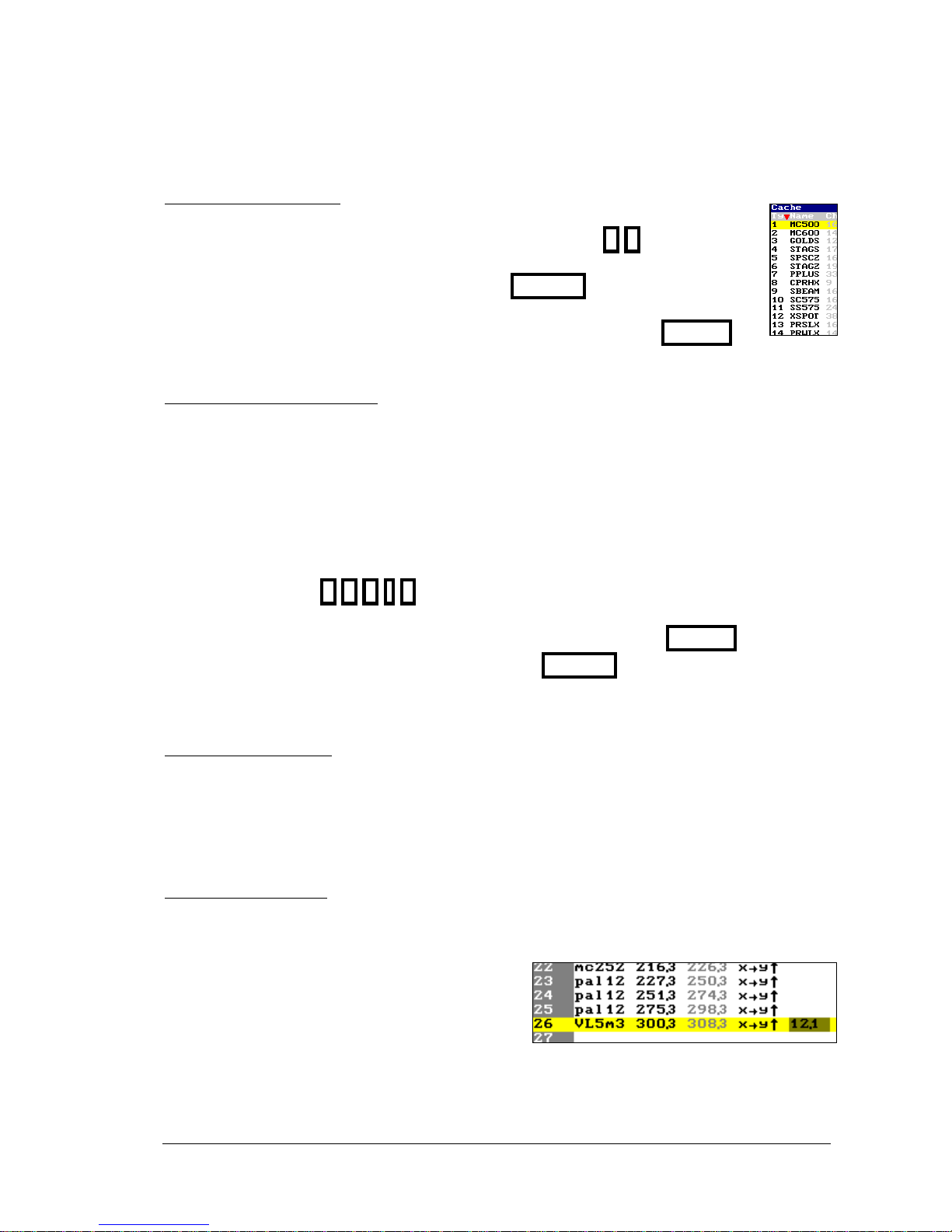
MENU 0 4 (a: menu command)
FIXTURE FIXTURE (b: quick command)
This screen has 3 zones:
Cache that is a list of the types (fixture definitions), you can use them in the Patch.
Fixture Definition that presents the fixture definition that it is selected in the Cache or Patch
list.
Patch that has the fixtures configuration, and include the type of each fixture number, its Dmx
direction, etc... After a Reset this Fixture Patch always is empty.
LEVITON 8700 SERIES
Page 30
4-2 FIXTURES PATCH
4.1. EDITING THE PATCH
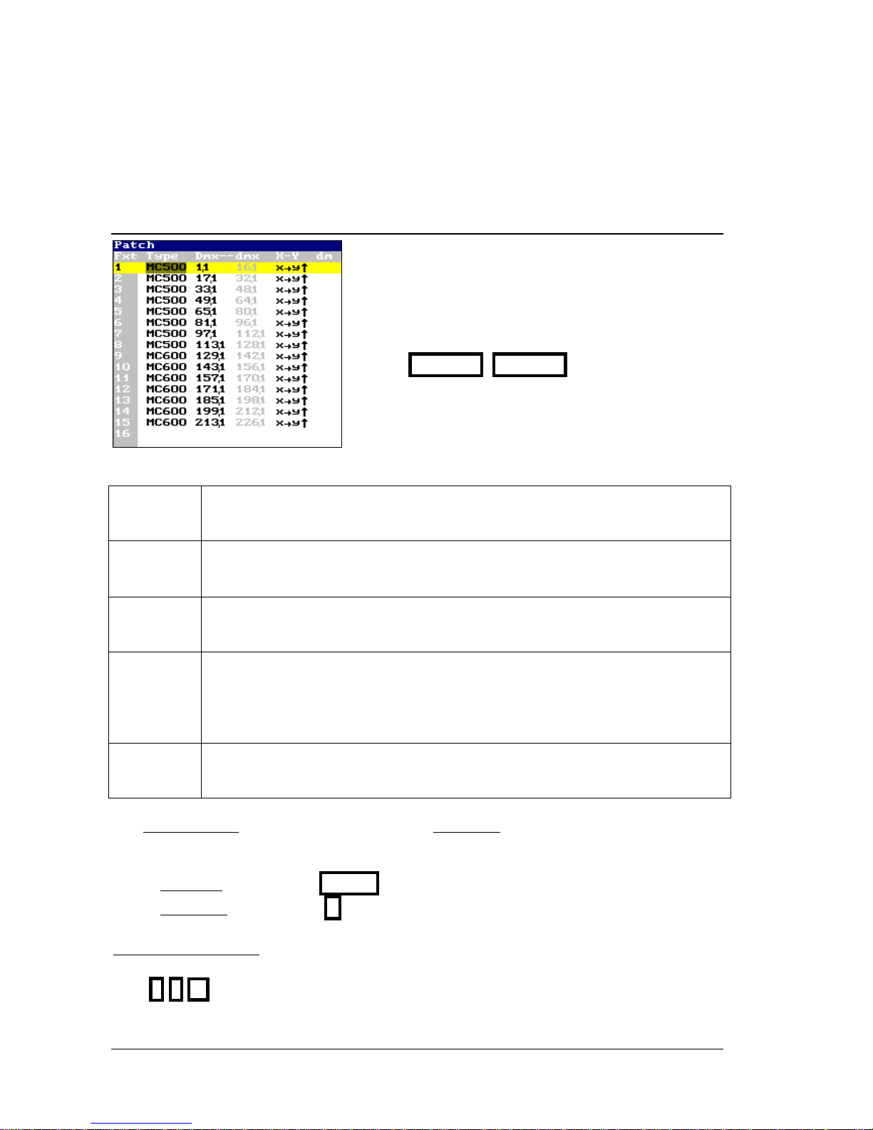
Each Patch line has the configuration about a physical
moving light. Each connected moving light (fixture) must
be defined in this Patch.
Each time that you open this menu, the Patch list is
active. At any moment you can active the Patch list
pressing FIXTURE FIXTURE
Each Fixture is defined by:
Fxt
Fixture number
This number is used by the system to select it.
Type
Name of the fixture definition
This type is edited entering its index number (1 to 24) from the Cache list
Dmx--dmx
DMX direction
Are the DMX directions used by the fixtures (only the first direction is editable).
X-Y
Trackball movement
Permits to exchange or invert the movement parameters (Pan-Tilt), to obtain a
homogeneous movement of each fixtures in the trackball, independently of its
physical localization.
dm
External Dimmer
If the fixture has an external dimmer, this is its DMX direction.
The selected fixture is in the yellow area, and its active data (cell) in the brown area. Use the
arrow keys or the external mouse to select the desired data to edit.
Each time that a data is edited, its cell appears in red area and in this status, it is possible:
To accept the data: press ENTER or moving the cursor to other cell.
To discard the data: press C
If the active data is Fix:
From here you can search a fixture of the list. Example: To access to the fixture 10, at any Fxt cell
press 1 0
LEVITON 8700 SERIES
Page 31
FIXTURES PATCH 4-3
If the active data is Type:
To edit the desired type for this fixture, enter its index number that appears in the
Cache list. Example. To edit a XSPOT type, enter the number 1 2
To delete the configured fixture, completely, press DELETE here.
To copy this fixture with the same Type that the previous fixture, press INSERT . If
it is possible, the system assigns to this fixture the next DMX directions.
If the active data is Dmx-dmx:
Edit the DMX direction of the fixture that must be the same that the configured in the physical
moving light. DMX direction has the next format: DDD.L
DDD is the DMX channel (1 to 512)
.L is the line number or DMX output (1 to 4), and the total number of DMX
outputs is in accordance with the 8700 Series model.
Address a fixture in the DMX channel 252 of the line 2, pressing:
2 5 2 . 2
To edit the next DMX direction (in relation to the previous fixture) press INSERT.
To delete the DMX direction (only the direction) press DELETE.
The last DMX direction used by this fixtures is presented in gray and they cannot be edited.
If the active data is X-Y:
It is possible to configure the response of pan (X) and tilt (Y) of this fixture in the trackball. In
this cell the options appear in a red window. Enter the index number of the option.
In many case it is necessary to check this response, for this reason, each time that the active data
is X-Y, you can use the TB☼ to move the fixtures and the Level to control the fixture
dimmer.
If the active data is dm:
Only if the fixture type is defined with external dimmer, here you can edit the DMX direction for
this dimmer.
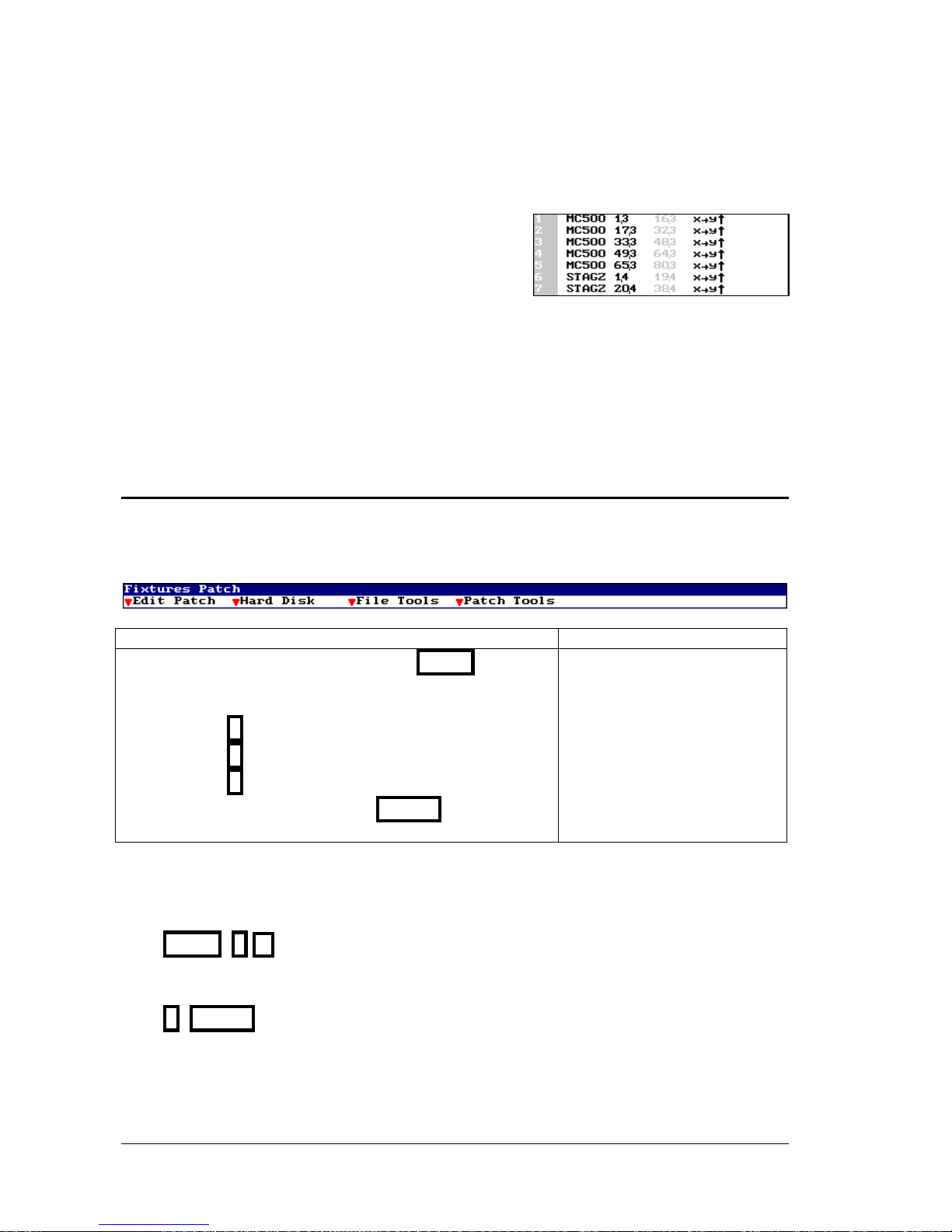
Fixture 26 is controlling a VL5 that it is
connected to the dimmer 12 in DMX-1, fixture 26
has the DMX direction 300 in DMX-3
LEVITON 8700 SERIES
Page 32
4-4 FIXTURES PATCH
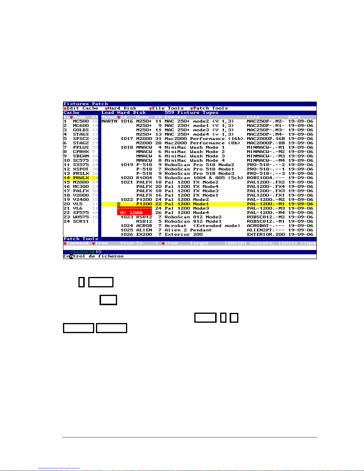
Patch to control 5 Mac500 connected to the output
DMX-3, & 2 Stage Zoom connected to the output DMX4
The types have been charged from the Cache list, where:
The Stage Zoom type is the number 6 - STAGZ (19 channels) & the Mac 500 type is the
number 1 - MC500 (16 channels).
Cache list contents 24 types, with an index number (Ty), an identification name (Name) and
the number of DMX channels that needs for its control (Ch).
4.2. LOADING A NEW FIXTURE DEFINITION
If you want use a type that is not in the Cache list, it is possible to load it from the types-library.
This types-library can be placed in the hard disk, USB memory or floppy disk. To select where
the desired type is, access to the Setup-line:
Using the functions keys Using mouse
• Access to the Setup-line pressing MENU.
• Select the second option (arrow keys or mouse) and
enter:
0 to select 0: Hard Disk
1 to select 1: Floppy Disk
2 to select 2: USB Disk
• Accept the option pressing ENTER
Hard Disk
0: Hard Disk
1: Floppy Disk
2: USB Disk
To replace a Cache type, this must be not used in the Patch.
To access to the Cache list from the Patch list, you can use the mouse or press:
MENU 1
Select a not-used type, and execute the option 2: Load, with the mouse or pressing:
2 ENTER
LEVITON 8700 SERIES
Page 33
FIXTURES PATCH 4-5
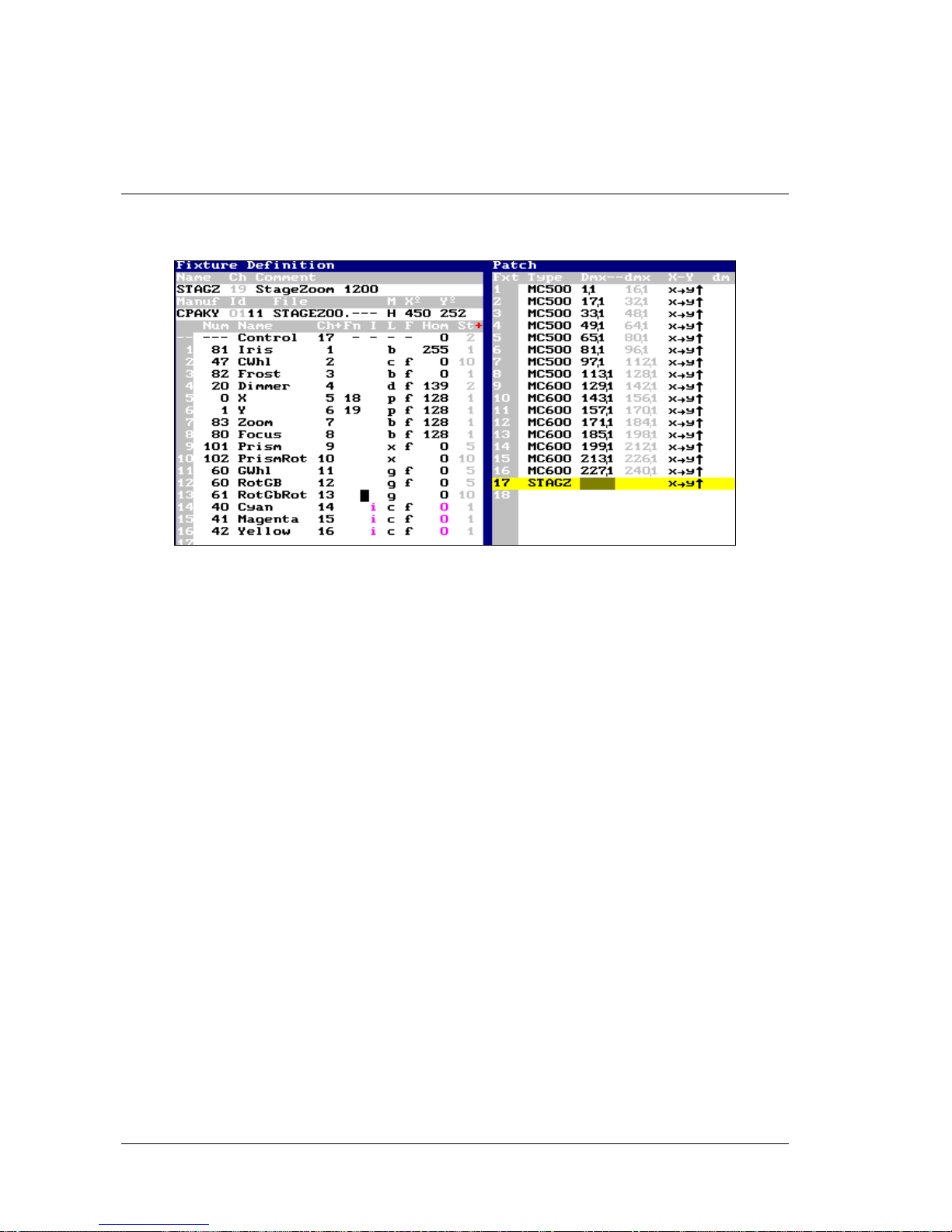
The types-library appears, ordered by manufactures, to the right of the screen. Use the arrow keys
or the mouse to select the desired library type. There is a search function by manufactures. This
function is available in any Manuf cell; here, enter the index number of the desired manufacture
to access to this part of the types-library.
To select the type to load, access to its cell T and execute the option 0: Load, pressing:
0 ENTER (or use the mouse 0: Load)
Quit pressing EXIT
To return to Patch, you can use the mouse, press MENU 0 or
FIXTURE FIXTURE
If the types-library has not the desired type, the user can edit it. More information about new
types creation in Chapter 17.
Note:
If the selected type in Cache is been used in the Patch, this type cannot be substituted; the
option 2: Load is not active.
LEVITON 8700 SERIES
Page 34
4-6 FIXTURES PATCH
4.2.1. THE FIXTURE DEFINITION INFORMATION
Fixture Definition is an interactive window. It is synchronized with the selected type (in Patch
or Cache) and presets us the definition of each parameter of the fixture type.
More information in Chapter 17-Fixtures Definition.
LEVITON 8700 SERIES
Page 35
5. EDITOR
The editor is used to select channels and fixtures, and to assign dimmer levels and parameter
values, with the objective to set the desired scene and store it as cue or group. Also, it’s possible
to select cues and groups, as well as the outputs of any playback for editions more versatile. In
cues and groups only are stored the editor contents.
The pictures can be edited in stage or in blind, because the 8700 Series has 2 editors:
The Stage editor works in live controlling totally the scene (including the playbacks outputs).
The Blind editor doesn’t affect to the scene output.
Only one of these editors is active. To toggle between the Stage and Blind editors, press
BLIND. The activation of one editor doesn’t affect to the contents of the other editor.
When Blind editor is active, the BLIND LED is lit, and in the status line, the flag
Blind appears in a red field. The auxiliary screen presents only the editor contents when
Blind is active; and the whole scene when the Stage is active.
Both editors use the same commands to do the same actions.
5.1 DEFAULT SELECTION
Each Item is selected for its function key and a number.
CHANNEL 2 5
GROUP 3
With the objective to decrement the keys number to press, at the beginning of the command
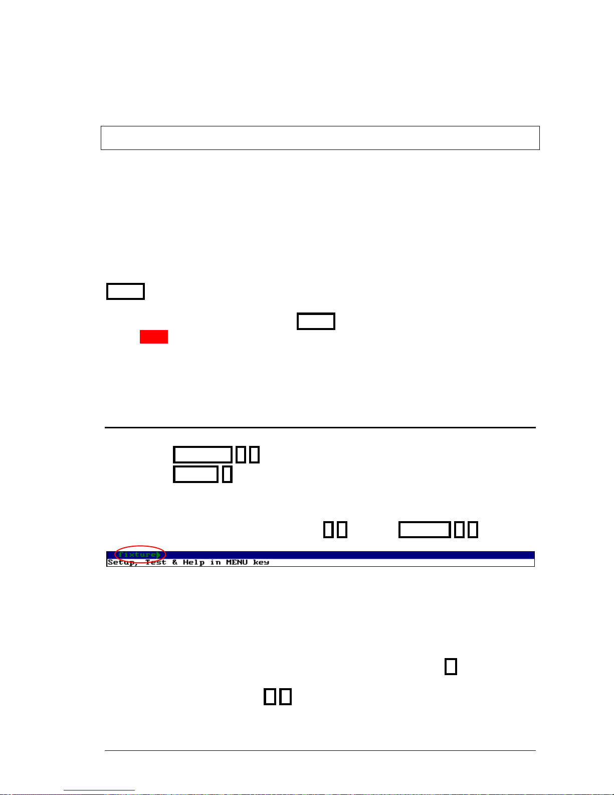
line always is present the last item used, and it’s the default selection. Example, if here appears
fixture`, to select the fixture 25 is enough press 2 5, instead of FIXTURE 2 5
The default selection can be: channel`, fixture`, group` or cue`
After a Reset the default selection always is channel`
Besides this, the command line presents the last pressed keys. These pressed keys are cleared
each time that an action is done.
To delete the last pressed key, that is presented in the command line, press C. This function is
used to delete a bad entered number, and it doesn’t affect to the editor contents. To clear
completely the command line press C C
LEVITON 8700 SERIES
Page 36
5-2 EDITOR
5.2 CHANNELS
The channels are used to control conventional dimmers. Their behavior is HTP & No-Tracking.
Inside editor a channel can be:
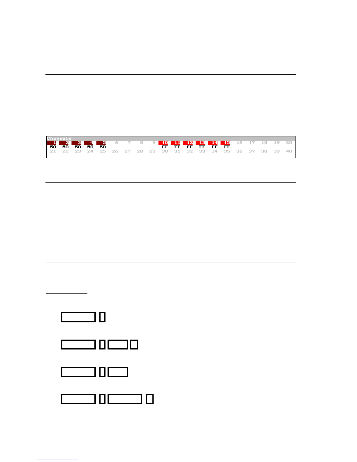
Present: The channel comes from a previous edition and it’s presented in a brown field.
Pre-selected: The channel is in the editor waiting a level edition and presents its number in red.
Selected: The channel level is finished of editing and can be edited again, and it’s presented in a
red field.
5.2.1 HTP & NO-TRACKING
HTP: The channel takes the higher level among the playbacks that are controlling it. In other
words, the playback that has the higher level is the playback that controls the channel.
As exception: Always that a channel is inside the Stage editor, the channel is controlled by this
editor; since the Stage editor takes priority over any playbacks.
No-Tracking: When a channel isn’t controlled for playbacks or editor, the channel is always at
0%.
5.2.2 SELECTING CHANNELS
The number of channels of the system is configured in the menu 50: Console Configuration.
The system can control from 0 to 2000 channels.
Basic selections:
Select the channel #
CHANNEL #
Select a range from the channel # to #’
CHANNEL # THRU #’
Select a range from the channel # to the last
CHANNEL # THRU
Select the channel # and the channel #’
CHANNEL # CHANNEL #’
LEVITON 8700 SERIES
Page 37
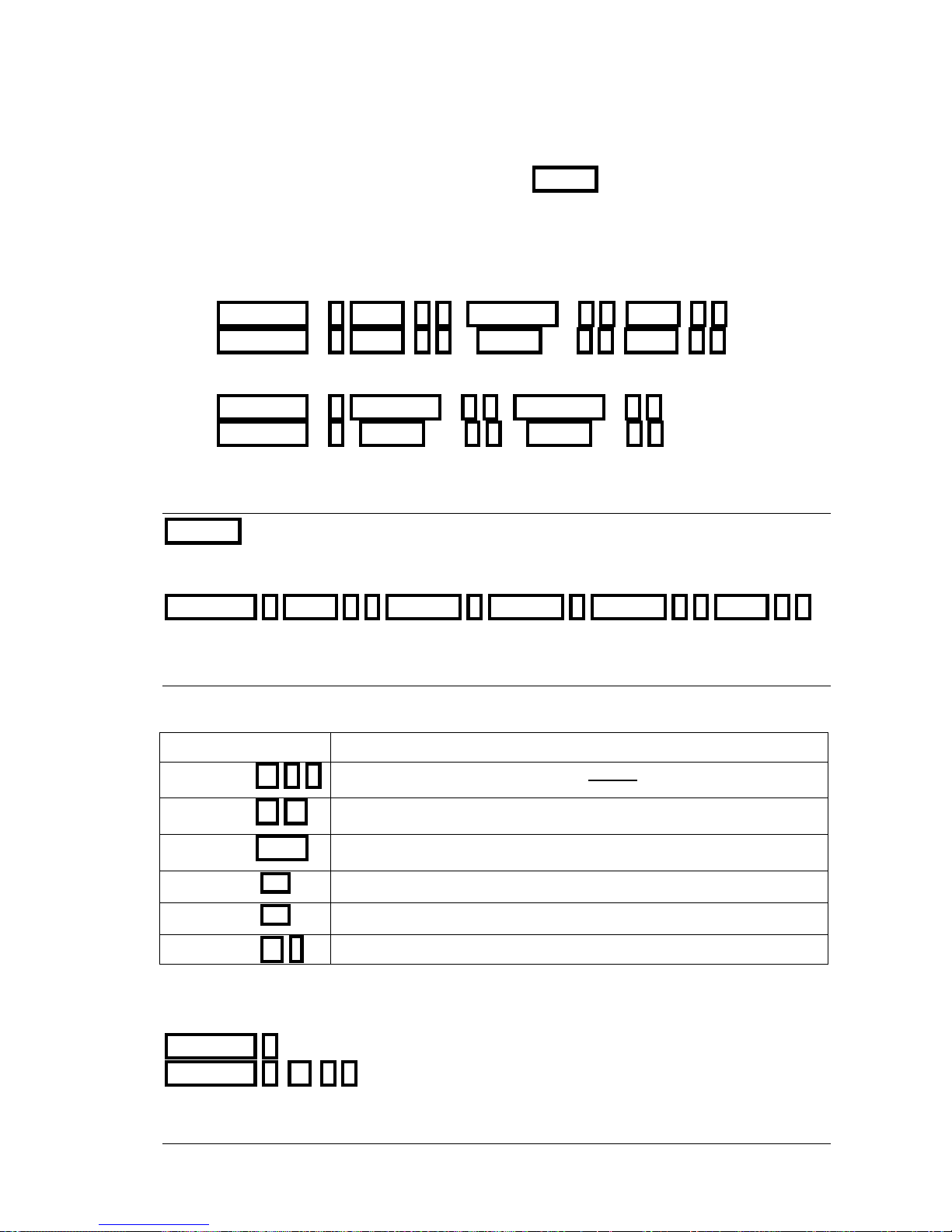
EDITOR 5-3
These basic selections can be combined as desired. ENTER can be used as “AND” function
among basic selections.
Some examples:
Select the channels 1 to 45 and 50 to 52:
CHANNEL 1 THRU 4 5 CHANNEL 5 0 THRU 5 2
CHANNEL 1 THRU 4 5 ENTER 5 0 THRU 5 2
Select the channels 1, 45, and 58
CHANNEL 1 CHANNEL 4 5 CHANNEL 5 8
CHANNEL 1 ENTER 4 5 ENTER 5 8
5.2.3 EXCLUDING CHANNELS
EXCEPT permits us to exclude channels of a selected range.
Select the channels 1 to 57, except the channels 5, 7 and 10 to 15:
CHANNEL 1 THRU 5 7 EXCEPT 5 EXCEPT 7 EXCEPT 1 0 THRU 1 5
5.2.4 EDITING CHANNELS
After selecting channels, {channels}, it’s possible to assign them a level using one of these
methods:
{Channels} Level
Continuous adjustment of level (moving the vertical wheel)
{Channels} @ # #
Level assignation with number using 2 digits, from 00 to 99
{Channels} @ @
Setting at 100% (FF)
{Channels} CALL
Setting at 100% in a fading of 2 seconds.
{Channels} ½½
Increase the level a 5% (+%)
{Channels} ¾¾
Decrease the level a 5% (-%)
{Channels} @ •
Assignation of the last level used from the numerical keyboard.
While the channels are selected, it’s possible to edit it as many times as necessary.
Examples for the channel 1:
CHANNEL 1 Level Control of level manual.
CHANNEL 1 @ 0 5 Set its level at 5%.
LEVITON 8700 SERIES
Page 38

5-4 EDITOR
CHANNEL 1 @ @ Set its level at 100% (FF)
CHANNEL 1 CALL Set its level at 100% (FF) in a fading of 2 seconds.
CHANNEL 1 ½½ Increase its level a 5%.
When these editions are done in the Stage editor, they are active in scene and take control over
any other playbacks output.
Note:
Selected & pre-selected channels are ready for edition. At the beginning of a new selection, the
previous selected are as presents
2 Menus
The level percentage of +% and –% se can be configured in the menu 30: Editor & Times
These keys can be pressed and hold down pressed to go applying increments up to arrive the
desired level/frame.
5.2.5 SELECTING ALL THE ITEMS IN THE EDITOR
If the editor has channels presents (in a brown field) and selected (in a red field), it’s possible to
select all the items as selected items (in a red field) for a same edition, pressing:
CHANNEL THRU
After, it’s possible to edit them, maintaining the proportionality: Level, ½½ , or setting the
same value for all they: @ # #
5.2.6 INVERT FUNCTION
INVERT toggles between the selected items and present items. This function is very used to
return to the edition of the present items.
The channels 23 and 45 are selected, and the channels 1 to 5 and 8 are presents.
To select the channels 1 to 5 and 8 to edit them, press INVERT
LEVITON 8700 SERIES
Page 39
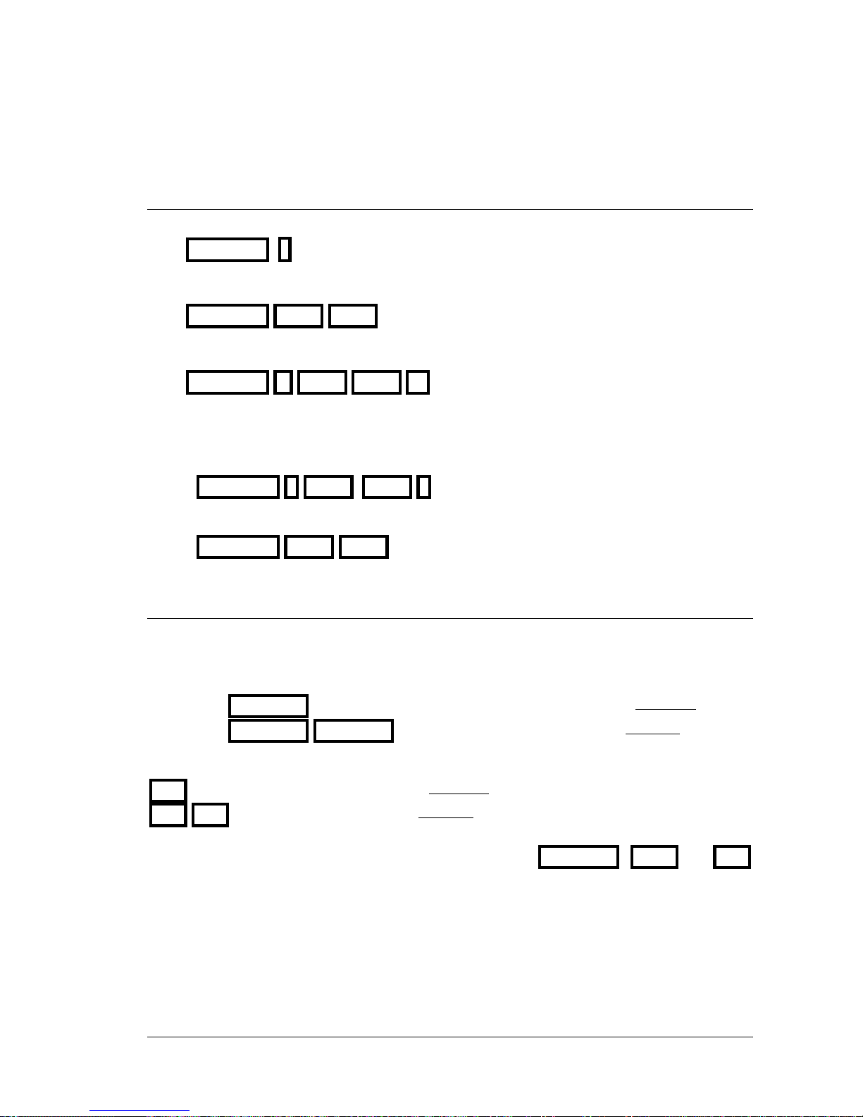
EDITOR 5-5
5.2.7 OTHERS SELECTIONS
Select again the last selection of channels:
CHANNEL •
Select all the channels in editor and scene:
CHANNEL THRU THRU
Select the channels in scene & editor inside a range:
CHANNEL #’ THRU THRU #’’
Examples. The odd channels from 1 to 17 are in scene.
To select the channels 1, 3, 5 and 7:
CHANNEL 1 THRU THRU 7
To select the odd channels from 1 to 17 (the scene channels)
CHANNEL THRU THRU
5.2.8 RELEASING ITEMS OF THE EDITOR
When it’s needed to eliminate items of the picture in editor, these must be released. A released
channel fades at 0%.
To release only selected channel (in a red field), use one of these options:
{channels} RELEASE
The channels fade at 0% in 2 seconds
{channels} RELEASE RELEASE
The channels jump at 0% suddenly
To release all the items (presents and selected), use one of these options:
RST
The channels fade at 0% in 2 seconds
RST RST
The channels jump at 0% suddenly
2 Menus: The default time editor (2 seconds) used in the RELEASE , CALL and RST
functions, can be edited inside the menu 30: Editor & Times
LEVITON 8700 SERIES
Page 40
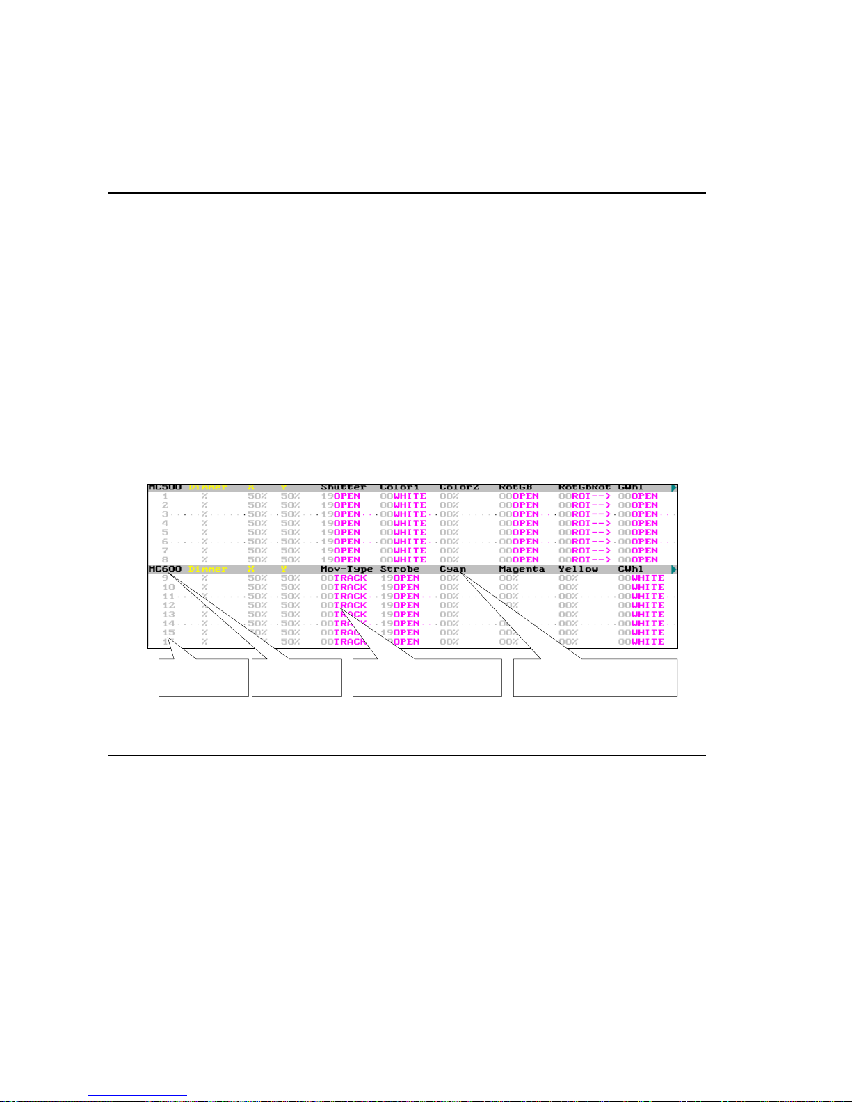
5-6 EDITOR
5.3 FIXTURES
The fixture is an item that it permits to control a moving light. Each moving light is controlled
for a fixture number, and from this fixture number we have access to all its parameters.
The first step is the configuration of the type and number of moving light to use. This
configuration is done inside the menu 04: Fixtures (See chapter 4 – Fixtures Patch)
The console can be configured to control a maximum of 512 fixtures. The configured fixtures
cannot exceed the maximum number of attributes. The maximum number of attributes appears
inside the menu 50: Console Configuration.
In this chapter is based in the next fixtures configuration:
Fixtures 1 to 8 are configured as Mac 500 (MC500)
Fixtures 9 to 16 are configured as Mac 600 (MC600)
The auxiliary screen shows these fixtures as:
Fixture
number
Parameters values Parameter name Fixtures type
5.3.1 THE FIXTURES IN THE EDITOR
It’s possible to select one fixture, group or range to edit, at once, one or several of their
parameters. A fixture is composed for parameters, and each one controls a function of the
moving light.
In the editor, the fixtures can be:
Present, that is of a previous edition and it’s marked with a brown arrow near its number.
Selected, that is been edited and it’s marked with a red arrow near its number.
In the editor, a parameter can be:
Present, that is of a previous edition and it’s showed in a brown field.
Pre-selected, that is waiting be edited and its value is showed in red.
Selected that is being edited and it’s showed in a red field.
LEVITON 8700 SERIES
Page 41
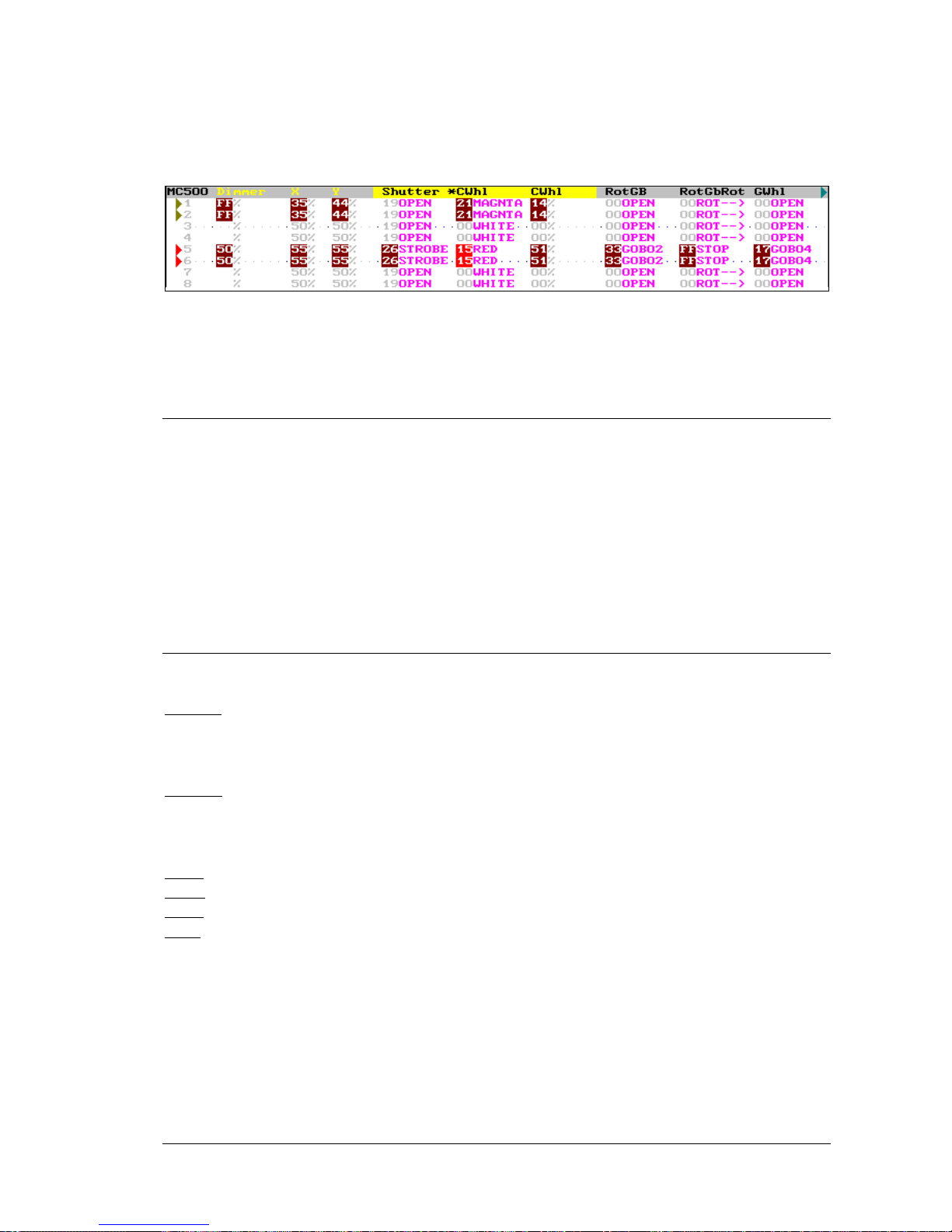
EDITOR 5-7
The Dimmer, if exists, works as HTP & No-Tracking, the same as the channels (see pg. 5-2).
The fixture parameters, except the Dimmer, work as LTP & Tracking.
5.3.2 LTP & TRACKING
LTP: The parameter takes the last value among the playbacks that are controlling it. In other
words, the last playback activated is the playback that controls the parameter.
As exception: Always that a parameter is inside the Stage editor, it’s controlled by this editor;
since the Stage editor takes priority over any playbacks.
Tracking: When the playback that controls the parameter is deactivated or when the parameter is
released of the Stage editor, the parameter maintains its value in tracking mode. The tracking
value is maintained until a playback or editor changes it.
5.3.3 ABOUT THE FIXTURE PARAMETERS
The fixture parameters are grouped for functionality:
Position parameters: They control the movement of the mirror or moving head. The principals
position parameters are X (pan) and Y (tilt), they have in special that can be edited using the
Trackball (TB) beside the control wheels.
Dimmer parameters: They control the intensity of the beam. The principal dimmer parameter is
the dimmer that works as HTP & No-Tracking, and can be edited using the vertical wheel or
Joystick (Level) and in the control wheels.
Color parameters: They control the beam color and are edited using the control wheels.
Gobo parameters: They control the gobos and are edited using the control wheels.
Beam parameters: They control the beam shape and are edited using the control wheels.
X-tra parameters: They control the rest of the functions no included in the previous groups (as
prism control, macro control, speed control, etc.) and are edited using the control wheels.
Each parameter has a Home value that is its neutral value. Example: The parameter Color1, has
its Home value at White (white beam).
Each fixture parameter has defined one or more steps. Each parameter step identifies a concrete
function of the parameter. Example: a color wheel with 8 colors will have defined 8 steps, one
step per color.
LEVITON 8700 SERIES
Page 42
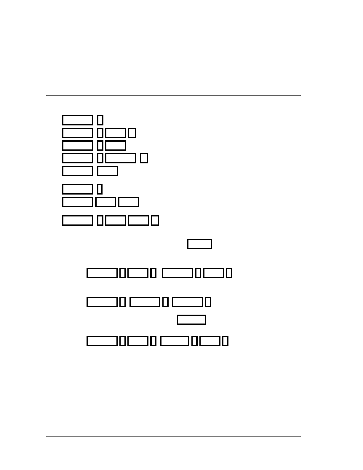
5-8 EDITOR
5.3.4 SELECTING FIXTURES
Basic selections:
FIXTURE #
Select the fixture #
FIXTURE # THRU #’
Select a range from fixture # to #’
FIXTURE # THRU
Select a range form fixture # to the last fixture
FIXTURE # FIXTURE #’
Select the fixture # and the fixture #’
FIXTURE THRU
Select all the fixtures that are in the editor as selected
fixtures.
FIXTURE •
Repeat the last selection done
FIXTURE THRU THRU
Select all the fixtures that are in the editor & in the
scene
FIXTURE # THRU THRU #’
Select all the fixtures of the range that are in the
editor & in the scene
These basic selections can be combined as desired. ENTER can be used as “AND” function
among basic selections.
Select the fixtures 1 to 3 and the fixtures 5 to 8
FIXTURE 1 THRU 3 FIXTURE 5 THRU 8
Select the fixtures 1, 5, & 8
FIXTURE 1 FIXTURE 5 FIXTURE 8
To eliminate fixtures of a range in a selection, use EXCEPT
Select the fixtures 1 to 8 except the fixtures 4 to 6
FIXTURE 1 THRU 8 EXCEPT 4 THRU 6
5.3.5 SELECTING AND EDITING PARAMETERS
The selected fixtures are edited editing one, several or all their parameters.
Some parameters are accessible at the moment that the fixture is selected:
• Dimmer - Its control is always available in the Level
• X and Y – Their control is always available in the TB
• And the first 3 parameters are available in the control wheels W15, W25 and W35
LEVITON 8700 SERIES
Page 43
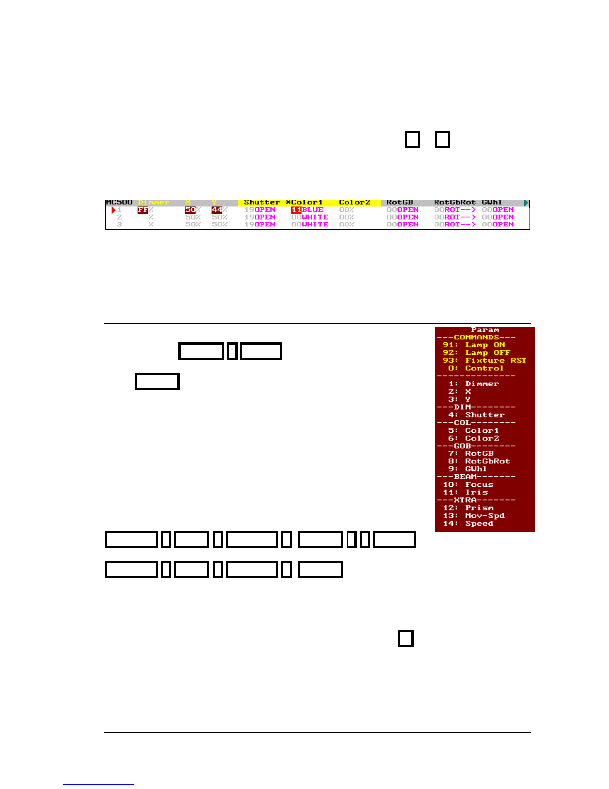
EDITOR 5-9
The rest of the parameters are available across the control wheels, but they must be searched
changing the active bank in the control wheels, for example pressing or
In the auxiliary screen, the parameters names in the active bank (available in wheels) are showed
in a yellow field. And the name of the selected parameters is marked with a *
The parameters are showed always in the same order, from left to right, as special parameters,
always appear Dimmer, X & Y; then, the rest of parameters ordered by functionalities, and
follow the next order: Position, Dimmer, Color, Gobo, Beam and X-tra.
5.3.6 EDITING A PARAMETER
The first step to edit a parameter is its selection:
{Fixtures} PARAM # ENTER
When PARAM is pressed, a red window is opened to show us the index
number of the parameters of the fixture. The selection can be done
clicking with the mouse.
Note:
If the selected fixtures are the several types (MC500 and MC600) the
PARAM window only shows the parameters of the fixtures of the first
type (MC500).
Example. To select the Iris of the fixtures 1 to 3 and 5 press:
FIXTURE 1 THRU 3 FIXTURE 5 PARAM 1 1 ENTER
or
FIXTURE 1 THRU 3 FIXTURE 5 PARAM 11:Iris
The selection of a parameter implicates:
• Its localization in the auxiliary screen to see it.
• Its selection in W15, to control it using this control wheel.
• Its activation to can apply it a numeric edition, pressing @
5.3.7 NUMERIC EDITION
To edit the selected parameter numerically, press:
LEVITON 8700 SERIES
Page 44
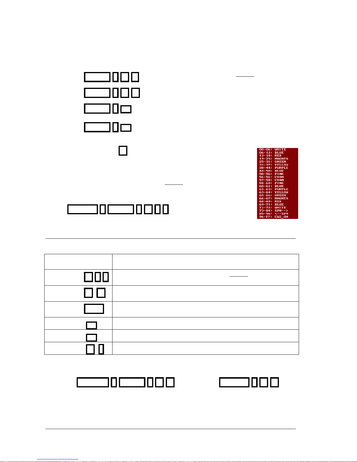
5-10 EDITOR
{fixtures} PARAM # @ #’
To set the parameter # at value #´ (2 digits)
{fixtures} PARAM # @ @
To set the parameter # at full (FF)
{fixtures} PARAM # ½½
Set the parameter # at its next step. If the parameter only
has 1 step, this command increases the parameter at %.
{fixtures} PARAM # ¾¾
Set the parameter # at previous step. If the parameter only
has 1 step, this command decreases the parameter at %.
In these commands, when @ is pressed, the system shows us a red window
with the values of the parameter to select the desired value easily. The selection
can be done using the external mouse.
Remember: The #’ value is always entered in 2 digits.
Example: Select the parameter 5 (Color1) of the fixture 1 and set it at
BLUE: FIXTURE 1 PARAM 5 @ 0 6
5.3.7.1 DIMMER
The Dimmer of the selected fixtures {fixtures} can be edited pressing:
{fixtures} Level
Manually, moving the vertical wheels or the joystick.
{fixtures} @ # #
Directly, assigning a numeric level entered in 2 digits (00 to 99)
{fixtures} @ @
Directly at 100% (FF)
{fixtures} CALL
At 100% (FF) with a fading of 2 seconds.
{fixtures} ½½
Increase the level a 5% (+%)
{fixtures} ¾¾
Decrease the level a 5% (-%)
{fixtures} @ •
Assigning a level as the last numeric level used.
Dimmer is the default parameter, since it’s not necessary to select it to edit it. Even so can be
selected and edited as the rest of the parameters.
FIXTURE 1 PARAM 1 @ @ is the same that FIXTURE 1 @ @
LEVITON 8700 SERIES
Page 45
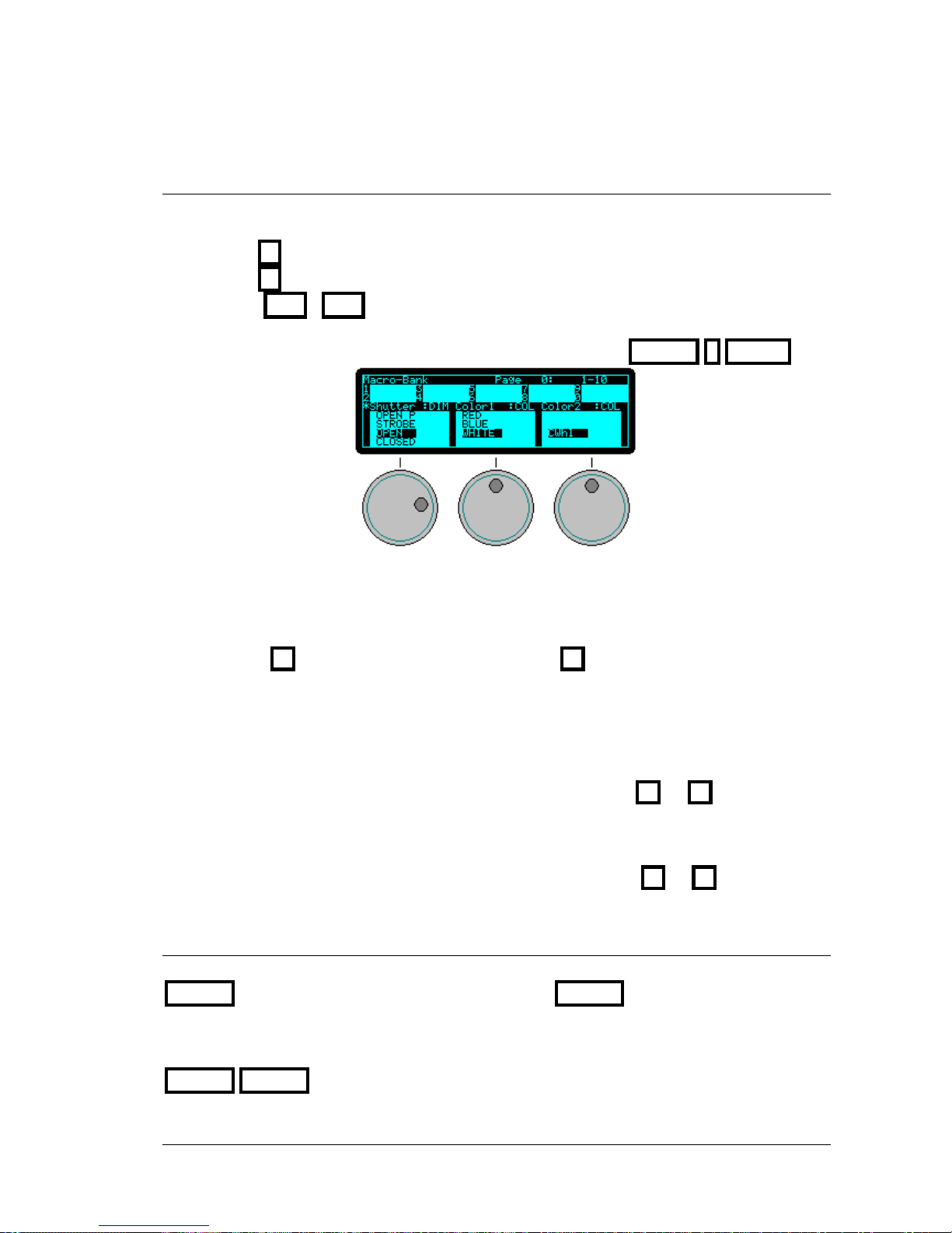
EDITOR 5-11
5.3.8 EDITION IN THE CONTROL WHEELS
Moving W15, W25 or W35, the parameters in active bank are edited. To change the active
bank to control other parameters, it’s possible use one of these options:
• Press to access to the next 3 parameters.
• Press to access to the previous 3 parameters.
• Press POS, COL, etc. to access to the first parameter of position, color, etc.
respectively.
• Select the parameter to control in W15 pressing {fixtures} PARAM # ENTER
The parameters in the active bank are showed in the display; each parameter shows its selected
step in a dark field. Moving the wheel is possible to scroll all the steps of the parameter.
The selected parameter is marked with a * near its name. The selected parameter also can be
edited pressing ↑↑ to access to the next step, or pressing ↓↓ to access to the previous step.
The selected parameter (marked with *) can be changed moving its wheel (W#5) or
pressing it (W#).
Exceptions:
When a parameter step has defined a Stop (s) will be needed press ↑↑ or ↓↓ to select its next
or previous step, since this selection is forbidden moving the wheel. The Stop is very used in
parameters that control more than one utility, for example, gobo + rotation, and it avoids that
editing the gobo with the wheel we can access to macros (or vice versus). When using the wheel
we arrive the Stop (s), the symbol * changes to #, and we must press ↑↑ or ↓↓
5.3.9 WHEEL KEY
When a parameter is being edited with its wheel, it’s possible to press and hold down pressed
WHEEL
T to do this edition in blind. After when WHEELS is released, the edition is
updated.
If the same parameter of several fixtures is to different values, select it (marked with *) and press
WHEEL WHEEL to copy to all the fixtures the value of the parameter of the first fixture.
LEVITON 8700 SERIES
Page 46
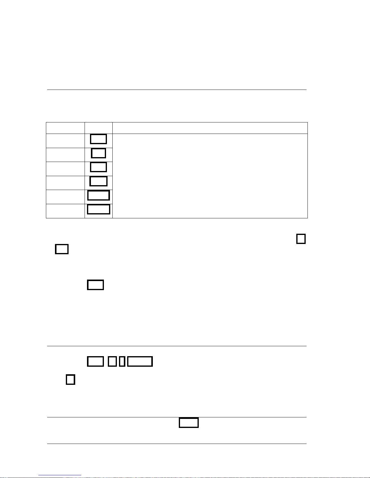
5-12 EDITOR
5.3.10 FUNCTIONAL EDITION - PALETTES
It’s possible to exam/select/edit parameters in accordance with its functionality.
To exam or select in the active bank the parameters of the desired functionally press:
Functionality Key Comments
Position
POS
Dimmer
DIM
Color
COL
Gobo
GOB
Beam
BEAM
X-tra
X-TRA
The auxiliary screen shows the parameters of the selected functionality
(except Dimmer, X and Y that always are), and if there are selected
fixtures, besides:
• The parameters are activated in the wheels. In concrete, the first
parameter of the functionality is loaded in W1, the next parameter
in W2, and the next parameter in W3.
• If BANKS is in AUTO mode, we have access to the palettes.
The palettes are pre-programmed values that permit a edition quick. The edition using palettes
can be done in 3 basic modes: Numeric selection, from the control wheels and from the keys 1
B
B
to 10
B
B
Remember that to have access automatically to the palettes, we must select fixtures. For example,
to access to the color palettes press:
{fixtures} COL
• A palette can be applied to any selection of fixtures (including stops of different types).
• The palette is a help to the edition, but its values are no references.
• After to apply a palette we can edit any parameter to modify parameters.
5.3.10.1 NUMERIC SELECTION OF A PALETTE
To apply a palette, for example a color palette, to the selected fixtures, press:
{fixtures} COL @ # ENTER
When @ is pressed, the system show us the list of the color palettes to help us to select the #.
The selection can be done using the mouse.
5.3.10.2 SELECTING PALETTES FROM THE CONTROL WHEELS
To apply a palette from the control wheels, press EDT+
LEVITON 8700 SERIES
Page 47
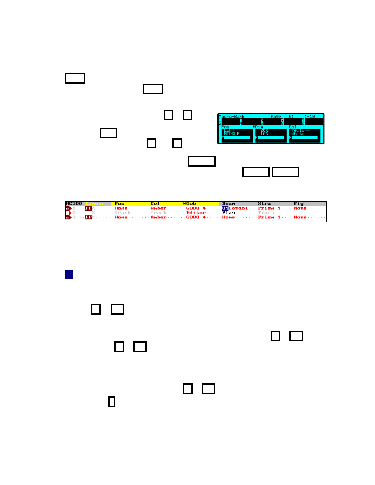
EDITOR 5-13
EDT+ toggles between the visualization the parameters or functionalities. When the
functionalities are presented, EDT+ active, the control wheels are palettes control:
To apply a palette, move the associated wheel, or:
• Change the active bank pressing or
• Access to the functionality; in example color,
pressing COL
• Select the palette pressing ↑↑ and ↓↓
If necessary, change the active wheel pressing in it (W#).
• Move a wheel is blind edition during that WHEEL T is pressed.
• Put the same active palette in all the selected fixtures pressing WHEEL WHEEL
Remember that the active wheel is marked with a * in the monitor and in the display.
In the visualization for functionalities, are showed their status and you can see:
Text When this functionality is edited from a palette.
Track When its parameters are all in Tracking mode.
Play When some of its parameters are controlled in any Playback
Editor When some of its parameters are edited in individually.
01Text When this functionality is edited from a library, in the example the library 01.
5.3.10.3 SELECTING PALETTES FROM THE BANKS KEYS
The keys 1B to 10B
B
are configured as direct access to different items pressing BANKS, and
are paged turning this wheel: BANKS5.
Pressing BANKS, a windows appears with the configuration options for 1
B
to 10B
B
The option 0 sets 1B to 10B
B
B in auto mode, changing with the edition process. This is the mode
by default.
The current configuration of the keys 1B to 10B
B
is showed in the display.
For the next commands, configure the keys 1B to 10B
B
in Auto mode, pressing:
BANKS 0 Or using the mouse BANKS 0:Auto
In this way, to apply palettes, for example of color and gobo, press:
LEVITON 8700 SERIES
Page 48
5-14 EDITOR
{fixtures} COL #
B
GOB #
B
B
And #B is the key associated to the desired palette, from 1B to 10B
B
B . It’s possible to press more
than one #
B
, the last pressed will be the active. B
Example with BANKS as 0:Auto
Select the fixture 1 and 3 and assign them the color palette 2: Yellow--, the gobo palette
4: Gobo4 and the dimmer palette 1: 10%:
FIXTURE 1 THRU 3 COL 2B GOB 4B
B
B DIM 1
B
B
If BANKS is in a fixed mode, for example as 3: POS, only the position palettes can be applied,
but in this case it’s no necessary to press POS to do it.
Set to position Middle the fixtures 1 and 3: FIXTURE 1 THRU 3 1
B
B
5.3.10.4 OTHER FUNCTIONAL SELECTIONS
ENTER and RELEASE can be used for the parameters of the selected functionality.
To release of the editor all the gobo parameters:
{fixtures} GOB RELEASE
To call to the editor all the parameters of position:
{fixtures} POS ENTER
5.3.11 THE HOME VALUES
The Home value is the neutral value of the parameter.
Set at Home all the parameters of the selected fixtures pressing:
{fixtures} HOME
Set at Home only the position parameters (for example), pressing:
{fixtures} POS HOME
LEVITON 8700 SERIES
Page 49
EDITOR 5-15
5.3.12 LIBRARIES
The libraries are exposed in the chapter 7. The console has libraries of each one of the
functionalities. The methods to apply libraries are similar as palettes. The most difference
between libraries and palettes is that the library values are references and these values can be
edited.
5.3.13 THE PARAMETER OF CONTROL
Same moving lights have a parameter to control some special functions of the moving light from
the console. The console has direct control of some of these special functions, as are turn-on the
lamp, turn-off the lamp and moving light reset.
To turn-on the lamps of the selected fixtures (ON), press:
{fixtures} PARAM 9 1
To turn-off the lamps of the selected fixtures (OFF), press:
{fixtures} PARAM 9 2
To reset the selected fixtures (RST), press:
{fixtures} PARAM 9 3
Note:
Each time that a lamp is turned-off, in accordance with the type lamp, is equivalent to 2-3 hours
of use, and normally will be necessary to wait a time to can turn-on it again.
Some fixtures have more special functions that these 3, to access to the rest of the special
functions, select the parameter of Control pressing:
FIXTURE 1 PARAM 0 @ #
When @ is pressed the red window shows us all the special functions (#).
This command works only with the fixtures of the first selected type.
The parameter of Control is not accessible in wheels.
5.3.14 INVERT
INVERT toggle between the present items (brown) and the selected items (red) inside editor.
Examples for an editor that has channels and fixtures:
Editing some channels & dimmers, press INVERT to edit the other channels and dimmers
LEVITON 8700 SERIES
Page 50
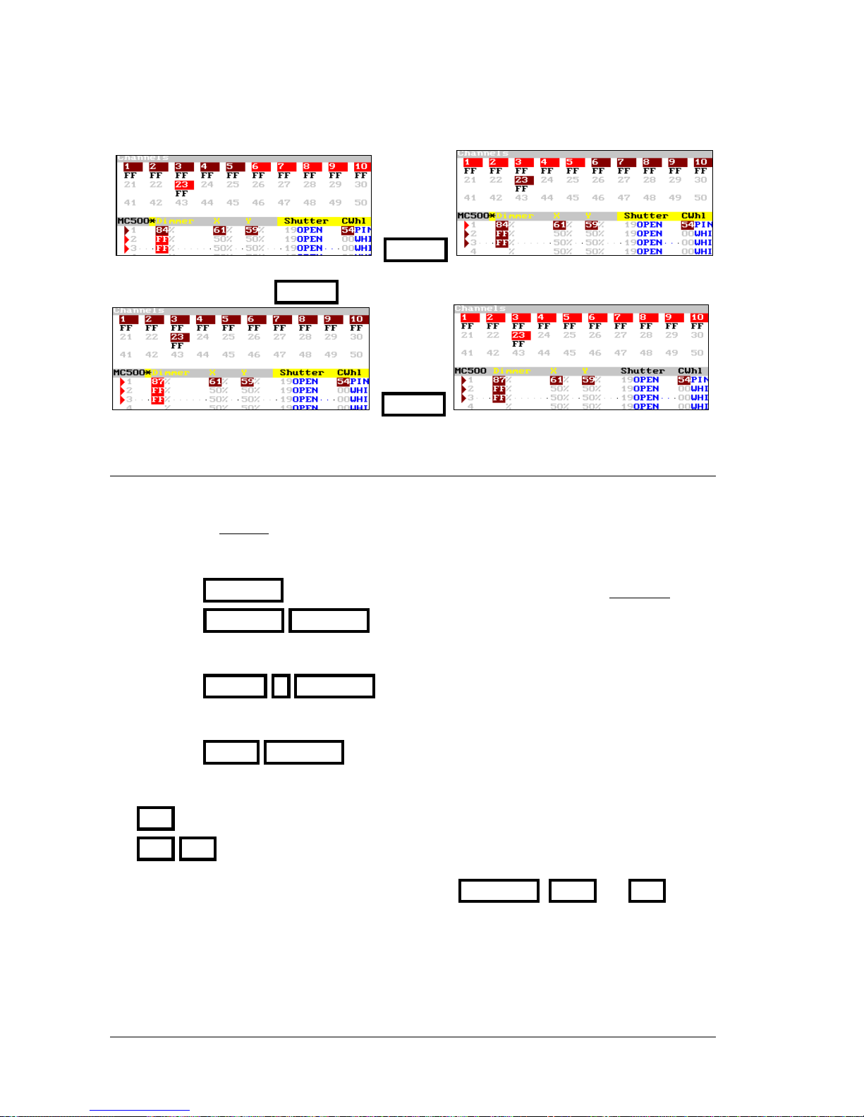
5-16 EDITOR
INVERT
Editing the fixtures, press INVERT to edit the channels
INVERT
5.3.15 RELEASING ITEMS OF THE EDITOR
When fixtures are released of the Stage editor, only the Dimmer parameters fade at 0%, since
that the Dimmer has the same behavior as channels. The rest of the fixture parameters maintain
its scene value in tracking mode.
To release all the parameters of the selected fixtures, press one of these options:
{fixtures} RELEASE Their Dimmers fade out editor in 2 seconds.
{fixtures} RELEASE RELEASE Their Dimmers jump at 0% suddenly.
To release only a parameter, press:
{fixtures} PARAM # RELEASE
To release all the parameters of a functionality (example of beam) press:
{fixtures} BEAM RELEASE
To release all the channels and fixtures that are in editor, press:
RST Dimmers & channels fade out editor in 2 seconds.
RST RST Dimmers & channels jump to 0% suddenly
2 Menu: The editor default time (2 seconds) used for RELEASE , CALL and RST, can be
changed inside menu 30: Editor & Times
LEVITON 8700 SERIES
Page 51
EDITOR 5-17
5.4 THE TRACKBALL
The Trackball, TB, has several function keys associated:
FINE
Used to set the sensibility of trackball and control wheels. Press FINE as many times as
necessary to set the sensibility:
Sensibility
FINE LED
Comments
Normal Off
High On
To change a value will be needed a large displacement of the TB, or
the control wheels, obtaining a better precision.
Low Blinking
To change a value will be needed a small displacement of the TB, or
the control wheels, obtaining an inferior precision but more agility.
TB
Used for configuration of the TB. Press TB as many times as necessary to set the behavior:
Behavior
TB LED
Comments
Normal Off
The TB controls the parameters X (pan) and Y (tilt)
None On
The TB is inactive
Orthogonal Blinking
The TB only controls one of these parameters, only X or only Y.
The parameter that the TB is controlling will be the parameter
that corresponds with the direction that has mayor displacement.
* If TB is at MOUSE mode, the first click in TB returns to TRACKBALL mode.
FLIP
Editing the position of a fixture, sometimes, it’s not possible to arrive the desired point. In these
cases, press FLIP for that the system edits a complementary values for X and Y with the
objective to arrive the same point from other perspective. Moreover FLIP can be used as special
effect, since that gets a movement quick and clear.
FLIP can be applied to the parameters X and Y, only to X, or only to Y.
FIXTURE 1 FLIP The parameters X and Y of fixtures 1 change their values.
FIXTURE 1 PARAM 2 FLIP Only the parameter X of fixtures 1 changes its value.
LEVITON 8700 SERIES
Page 52
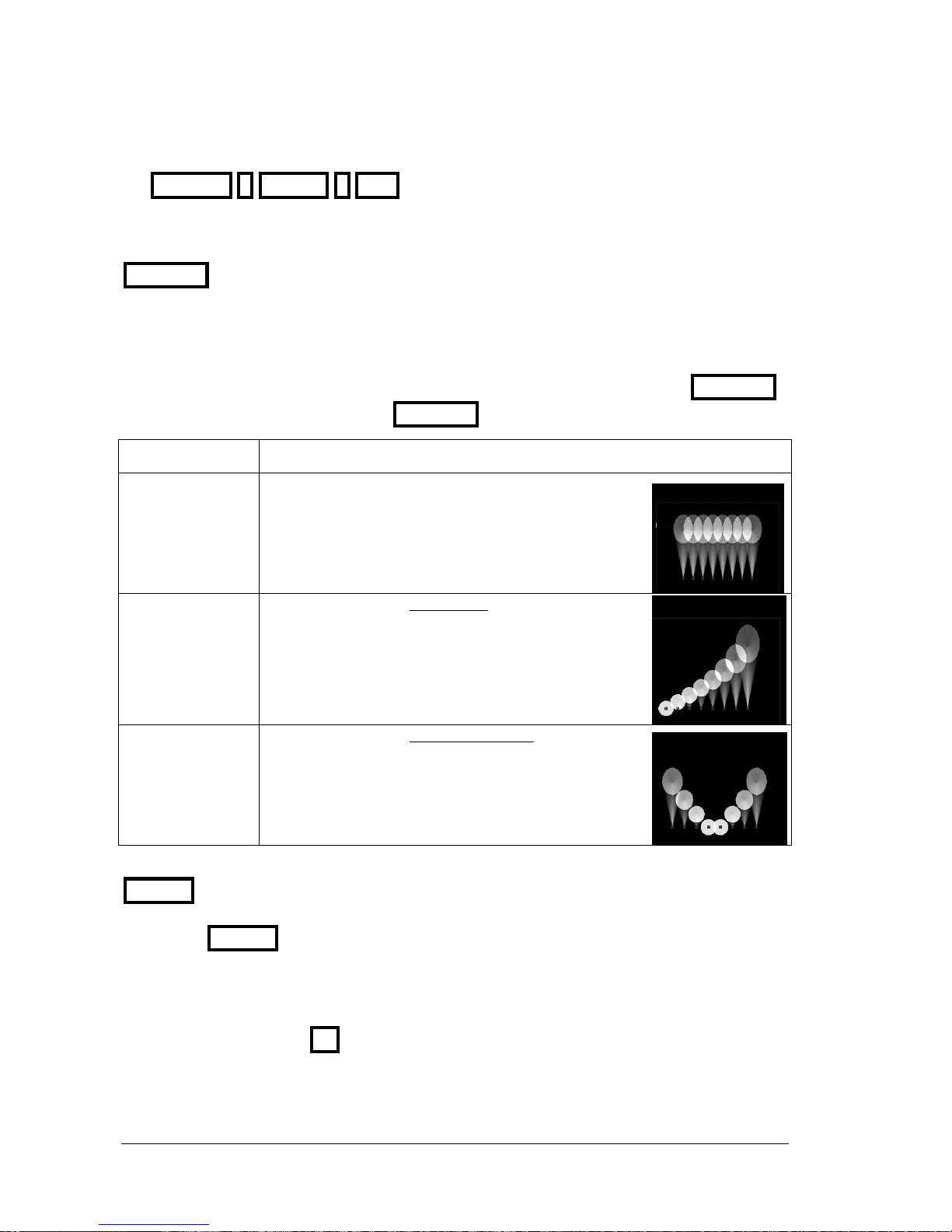
5-18 EDITOR
FIXTURE 1 PARAM 3 FLIP Only the parameter Y of fixtures 1 changes its value.
FAN-OUT
This function permits the edition, in a selection of several fixtures, of values for X &/or Y
parameters in relative mode.
This edition can be done using the TB or using W25 &/or W35.
Mainly, this function has 3 basic modes, and we select one of these modes pressing FAN-OUT
as many times as will be necessary. The FAN-OUT LED shows us its current mode:
FAN-OUT LED
Function mode
Off Fan-Out inactivated
X &/or Y edition isn’t affected for this function.
Example: Increase of Y of the fixtures 1 to 8
On Fan-Out activated in lineal mode.
X &/or Y edition has a relative value, in lineal mode,
between the first and last fixtures.
Example: Increase of Y of the fixtures 1 to 8
Blinking Fan-Out activated in symmetrical mode.
X &/or Y edition has a relative value, in symmetrical
mode, between the first and last fixtures.
Example: Increase of Y of the fixtures 1 to 8
MOUSE
This function permits set the trackball in MOUSE mode to use it as the external mouse. In this
mode when MOUSE is pressed is as a mouse click.
In this mode the trackball is lit in green.
Quit of this mode pressing TB
LEVITON 8700 SERIES
Page 53

EDITOR 5-19
5.5 THE STATUS LINE
The status line shows us flags about the editor contents. These flags are cfWX
c appears always that the editor has channels
f appears always that the editor has fixtures.
WX appears always that the editor has shapes
Note:
These same flags, cfWX, also appear in the exam of groups and cues.
LEVITON 8700 SERIES
Page 54

5-20 EDITOR
RESUME
Activate/deactivate Blind editor: BLIND
Selecting channels & fixtures. Examples for channels:
A channel: CHANNEL #
A range: CHANNEL # THRU #
Several ranges: CHANNEL # THRU # CHANNEL # THRU #
A group: CHANNEL # CHANNEL # // CHANNEL # ENTER # ...
The editor channels: CHANNEL THRU
The scene channels: CHANNEL THRU THRU
The last selection: CHANNEL •
Unselect channels: EXCEPT # EXCEPT # THRU #
Level for dimmers and channels:
Manual: {channels, fixtures} Level
Numerical: {channels, fixtures} @ #
At 100%: {channels, fixtures} @ @
At 100%, in 2 sc: {channels, fixtures} CALL
The last used: {channels, fixtures} @ •
Fixtures parameters:
Edit x/y: {fixtures} TB
Edit a parameter: {fixtures} PARAM # @ #
Edit a parameter using wheels, stage or blind mode: {fixtures} W#5 or WHEEL W#5 WHEEL
Access to the next or previous step: {fixtures}{parameter*} ↑↑ or ↓↓
Access to the next or previous parameter: {fixtures}{parameter*} or
Parameter of selected fixtures at the same value: {fixtures}{parameter*} WHEEL WHEEL
Using palettes (example color): {fixtures} COL @ # ENTER
All parameters at HOME: {fixtures} HOME
Select or release several parameters (example color): {fixtures} COL ENTER /RELEASE
Control commands: On, Off & Reset: {fixtures} PARAM 91 /92 /93
Releasing channels and parameters:
{Selection} RELEASE (RELEASE)
The whole editor RST (RST)
Delete command line: C (C)
Trackball
FINE, set the desired sensibility (normal, high, low)
ORTO, set the TB behavior (normal, none, orthogonal)
FLIP, search the same point with other values of x/y.
FAN-OUT, Edition of values for x/y in relative mode (lineal and symmetric)
LEVITON 8700 SERIES
Page 55
6. CUES & GROUPS
The console stores, in cues and groups, the channels and fixture parameters actives in the editor
(red or brown). Cues are used to playback them in effects, masters and crossfaders. The groups
are used as help in the selections and can be to playback in the masters & effects.
An organized store processing saves efforts at the time of configure the system playbacks.
Cues are numbered from 1 to 2000, admitting decimal numbers, example: 55.5, 1.9, etc.
Groups are numbered from 1 to 2000.
The number of cues and groups that can be stored in the system are in accordance with their
contents and the amount of free data memory:
Before to store cues and groups, configure the console inside the menu 50: Console
configuration and edit the needed Patch (menus 01, 02 y 04), since they affect to the scene.
6.1 STORING CUES & GROUPS
To store a cue edit in the editor the desired picture:
• Select channels and edit them a level.
• Select fixtures and edit their parameters.
This scene is named: {editor}
The cues need that the channels and/or fixtures are edited (level & values).
To store a group edit in the editor the desired picture or select the desired items:
• Select channels and optionally edit them a level. If no level is edited the channels are stored at
100%.
• Select fixtures and optionally edit their parameters. If no parameters are edited the fixtures
are stored only with their dimmers at 100%. Exception: If a fixture hasn’t Dimmer will be
needed to edit some parameter to store it in a group.
The result of this edition is named: {selection/editor}
To store the cue # press:
{editor} CUE # REC
To store the group # press:
{selection /editor} GROUP # REC
To store the next cue press:
{editor} CUE REC
{editor} REC
To store the next group press:
{selection /editor} GROUP # REC
LEVITON 8700 SERIES
Page 56
6-2 CUES & GROUPS
To store the next group loading a master press:
{selection/editor} LOAD M#
The next cue (or group) number is the last cue number used +1.
In case of cues, the next cue number is showed in the command line as Q1
If the number of cue (or group) that is been stored exists, the system requests us confirmation.
Press REC to confirm, or press C # REC to store it in other number.
When a cue or group has been stored, the editor is maintained. Now it’s possible use this editor
as start point for the next cue or group, or empty the editor pressing RST
Store a group to select the fixtures 1, 5, 7, and 10:
FIXTURE 1 FIXTURE 5 FIXTURE 7 FIXTURE 1 0 GROUP REC
Store the group 100 to set the position of the fixtures 1 & 3:
FIXTURE 1 TB FIXTURE 3 TB GROUP 100 REC
Commands as GROUP 1 @ 5 0 or GROUP 1 Level allow to use groups
directly in the editor.
6.1.1 CALLING TO THE EDITOR OF PLAYBACKS & DATA
The console only stores the editor contents, for this reason, there are commands to call into
editor to some scene items (playbacks) that we want that they form part of editor.
Pre-select (select without levels/values) into the editor, some scene items.
To pre-select all the channels or fixtures that are in scene, press:
CHANNEL THRU THRU
FIXTURE THRU THRU
To pre-select a range of channels or fixtures that are in scene, press:
CHANNEL # THRU THRU #’
FIXTURE # THRU THRU #’
To pre-select the whole scene, press:
ENTER ENTER
LEVITON 8700 SERIES
Page 57
CUES & GROUPS 6-3
To pre-select the outputs of one or several masters, press:
ENTER M#
ENTER M# M# M# ... (As many keys as necessary) ENTER
Remember: makes that the key is hold down pressed
makes that the key can be released
To pre-select the outputs of crossfader, press:
ENTER ASSIGN
Pre-select the contents of a cue, a group or a range.
To pre-select the contents of a cue or group press:
CUE # ENTER
GROUP # ENTER
To pre-select the contents of a range of cues or groups press:
CUE # THRU #’ ENTER
GROUP # THRU #’ ENTER
Call (select with levels/values) into the editor, some scene item:
To call the whole scene (channels and fixtures) press:
CALL CALL
To call the outputs the one of several masters, and/or crossfaders press:
CALL M#
CALL M# M# M#... (As many keys as necessary) CALL
CALL ASSIGN
Call into the editor to a cue, group or range:
Call a cue, group or range using a fade-in of 2 seconds:
CUE # CALL GROUP # CALL
CUE # THRU #’ CALL GROUP # THRU #’ CALL
Call a cue, group or range suddenly:
CUE # CALL CALL GROUP # CALL CALL
LEVITON 8700 SERIES
Page 58
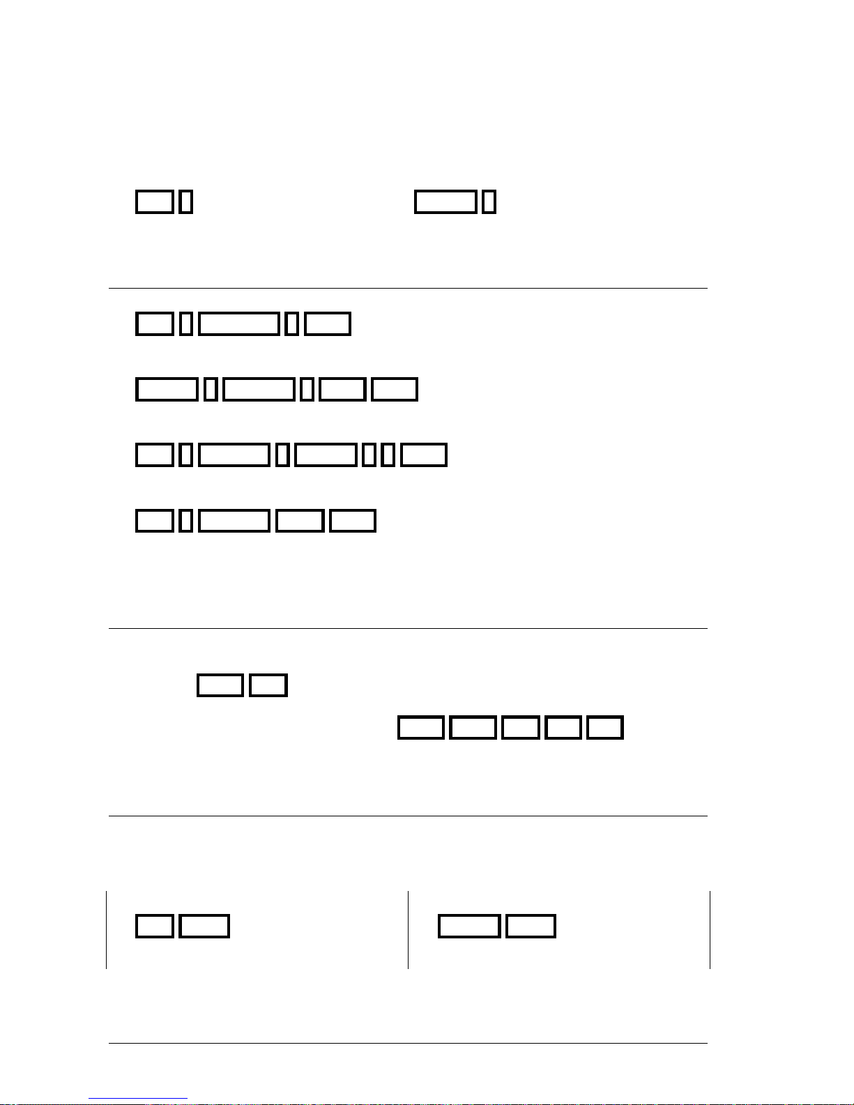
6-4 CUES & GROUPS
Call a cue or group controlled by the user:
CUE # Level GROUP # Level
Call into the editor, a channel fixture or parameters, as are stored in a cue or
group. Examples
Call to the channel 8, as is stored in cue 1, fading in 2 seconds:
CUE 1 CHANNEL 8 CALL
Call the fixture, as is stored in the group 1, suddenly:
GROUP 1 FIXTURE 8 CALL CALL
Call to the parameter 10 of the fixture 8, as it is stored in cue 1:
CUE 1 FIXTURE 8 PARAM 1 0 CALL
Call to the editor all fixtures, as stored, of cue 1:
CUE 1 FIXTURE THRU CALL
The editor controls a channel or fixture called into the Stage editor.
6.1.2 STORING THE SCENE IN THE NEXT CUE
There is a special command to store the whole scene as the next cue, directly with use the editor.
This command is:
{scene} CALL REC
This command is a short cut of the command: CALL CALL REC RST RST
6.1.3 EXAM OF CUES & GROUPS
It’s possible to exam a cue, a group, or list.
To exam the cue list press:
CUE EXAM
To exam the groups list press:
GROUP EXAM
To exam the cue #, press: To exam the group #, press:
LEVITON 8700 SERIES
Page 59
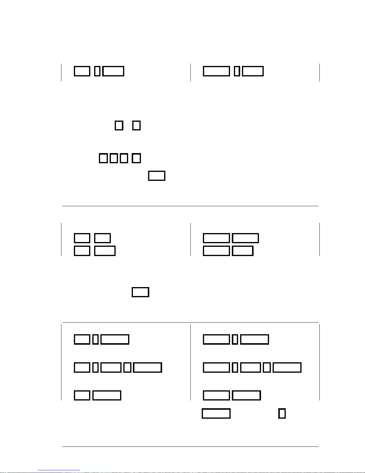
CUES & GROUPS 6-5
CUE # EXAM
GROUP # EXAM
The cue list or the groups list shows us all the cues or groups with their associated texts and other
general parameters, and also shows for each element a flag under the label cf:
c that has channels, f that has fixtures and that has shapes.
To page a list press or
The exam screen of a cue or group shows us the contents of this cue or group, its text and
generals parameters. To see more about this cue (or group) or to see the next or previous cue (or
group), press
To close any exam screen, press EXIT
6.1.4 ASSOCIATE A TEXT TO A CUE OR GROUP
To associate a text to a cue or group access to its edition list pressing:
For cues (2 options): For groups (2 options):
CUE CUE
CUE MDFY
GROUP GROUP
GROUP MDFY
Select the Text cell of the cue or group to edit, and type the desired text from the alphanumeric
keyboard.
Close this screen pressing EXIT
6.1.5 DELETE CUES OR GROUPS
To delete a cue press:
CUE # DELETE
To delete a group press:
GROUP # DELETE
To delete a cues range press:
CUE # THRU #’ DELETE
To delete a groups range press:
GROUP # THRU #’ DELETE
To delete all the console cues press:
CUE DELETE
To delete all the console groups press:
GROUP DELETE
The system requests confirmation. Confirm pressing DELETE or abort pressing C
LEVITON 8700 SERIES
Page 60
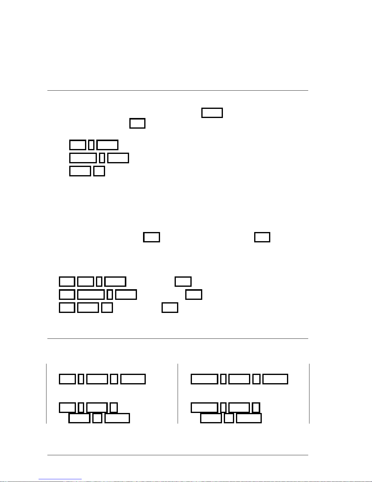
6-6 CUES & GROUPS
6.1.6 MODIFY A CUE OR GROUP
The contents of a cue or group can be modified at any moment. To modify it:
• Select the adequate editor, Stage or Blind, pressing BLND
• Empty the editor pressing RST
• Select the cue or group to modify it, using one of these options:
CUE # MDFY
GROUP # MDFY
MDFY M# To modify the cue or group loaded in master #
The selected cue or group fades in the editor in 2 seconds.
The status line shows us one of these flags:
Modify Q# in a red field, when we are modifying the cue #
Modify G# in a red field, when we are modifying the group #
• Modify it adding, editing or releasing channels and/or fixtures, {modifications}
• Store the modification pressing REC or abort the modification pressing RST
At any case, the flag Modify Q# disappears and the editor is emptied fading out in 2
seconds.
Resume:
RST CUE # MDFY {modifications} REC
RST GROUP # MDFY {modifications} REC
RST MDFY M# {modifications} REC
6.1.7 COPY CUES OR GROUPS
It’s possible to copy a cue (or group) in other cue (or group), coping the contents, the text and in
case of cues times & commands.
Copy cue # to cue #’
CUE # COPY #’ ENTER
Copy the group # to the group #’
GROUP # COPY #’ ENTER
Copy a cues range in other range:
CUE # THRU #’
COPY #’’ ENTER
Copy a groups range in other range:
GROUP # THRU #’
COPY #’’ ENTER
LEVITON 8700 SERIES
Page 61
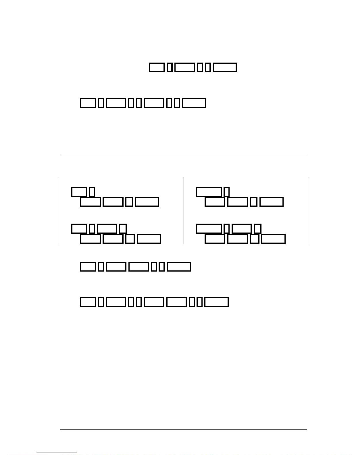
CUES & GROUPS 6-7
Copy the cue 1 as cue 25. CUE 1 COPY 2 5 ENTER
If the cue 25 exists, it will be modified, if not, it will be created.
Copy the cue 1 to 10, as cues 21 to 30.
CUE 1 THRU 1 0 COPY 2 1 ENTER
The copy of ranges keeps the original numbers. Suppose that in the previous example the
cue 1.5 is stored. After the exchange, will exists the cue 21.5
6.1.8 EXCHANGE CUES OR GROUPS
It’s possible to exchange 2 cues (or 2 group), exchanging their contents, texts and in case of cues,
their times & commands.
Exchange 2 cues
CUE #
COPY COPY #’ ENTER
Exchange 2 groups
GROUP #
COPY COPY #’ ENTER
Exchange 2 cues ranges
CUE # THRU #’
COPY COPY #’’ ENTER
Exchange 2 groups ranges
GROUP # THRU #’
COPY COPY #’’ ENTER
Exchange the cues 1 & 25.
CUE 1 COPY COPY 2 5 ENTER
If the cue 25 doesn’t is, will be created and the cue 1 will be deleted.
Exchange the cues 1 to 10 with the cues 21 to 30.
CUE 1 THRU 1 0 COPY COPY 2 1 ENTER
The exchange of ranges keeps the original numbers.
LEVITON 8700 SERIES
Page 62
6-8 CUES & GROUPS
6.2 CUE TIMES
The times programmed in a cue are used to execute this cue in crossfaders and masters. These
times are:
T↑
Fade-in time. It’s the time that the cue uses to fade from 0% to 100%.
T↓
Fade-out time. It’s the time that the scene uses to fade from 100% to 0%.
When the cue is executed in a crossfade, its T↓ is applied to the previous cue (scene cue).
When the cue is executes in a master, its T↓ is applied to this cue.
T
Wait time or auto time. It’s the time that the cue remains at 100% before begin its output
process automatically.
When the cue is executed in a crossfade, after this wait time, the next crossfade is started
automatically.
When the cue is executes in a master, after this wait time the master begins its output
process automatically.
T↑
Wait-in time. It’s the time that the cue waits before to fade from 0% to 100%.
T↓
Wait-out time. It’s the time that the cue waits before to fade from 100% to 0%.
When the cue is executed in a crossfade, its T↓ is applied to the previous cue (scene
cue).
When the cue is executes in a master, its T↓ is applied to this cue.
These times can be programmed or not. Any times combination is possible.
Note:
The fade times, T↑ and T↓, only are applied to channels and fixture Dimmers. The fixtures
parameters only are affected by these times if they are defined as Fade, inside the menu 04:
Fixtures (See chapter 17).
Each time that a cue is stored, it’s stored with the default times. These default times are
T↑=T↓=3 sec. and T =∞ (infinite); but these can be edited in menu 30 or in CUE CUE
screen.
The admitted times are 0.1 to 2000.9 sec. When a time is greater than 100 seconds, the decimal
point isn’t represented but is computed by the system.
LEVITON 8700 SERIES
Page 63
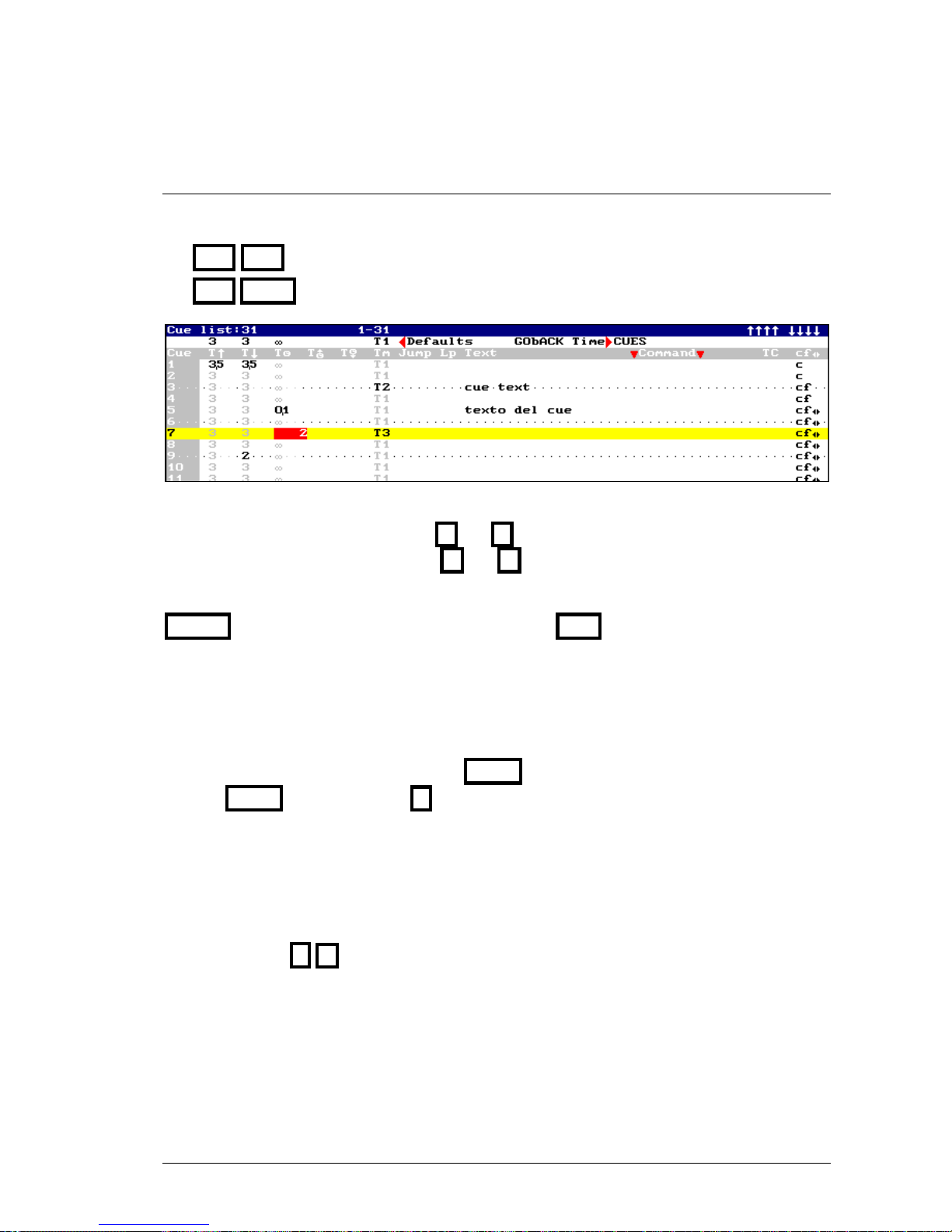
CUES & GROUPS 6-9
6.2.1 PROGRAMMING TIMES FROM THE CUE LIST
It’s possible to program any time for any cue inside the cue list. To open the cue list press one of
these options:
CUE CUE
CUE MDFY
The cue in edition is marked in a yellow cursor, and the data in edition is a red field.
Select the cue to edit it pressing and (or using the mouse).
Select the data to edit it pressing and (or using the mouse).
To edit this list, select the cue data, and enter its value. To accept the entered data press
ENTER or select other data. Close this screen pressing EXIT
The cue list shows us the default times in gray, and these times will be changed if the
corresponding default time is changed.
The default times are showed in this screen in its setup line. It’s possible to access to this setup
line to change any of these times pressing MENU or using the mouse. Return to the cue list
pressing MENU again, or pressing , or using the mouse.
To page the cue list turn MONITOR wheel
Direct access to a cue in the list:
Access to any Cue cell (in gray field)
And press # to select the cue #
2 Menus
The cues default times can be changed inside the menu 30: Editor & Times. See chapter 14.
LEVITON 8700 SERIES
Page 64
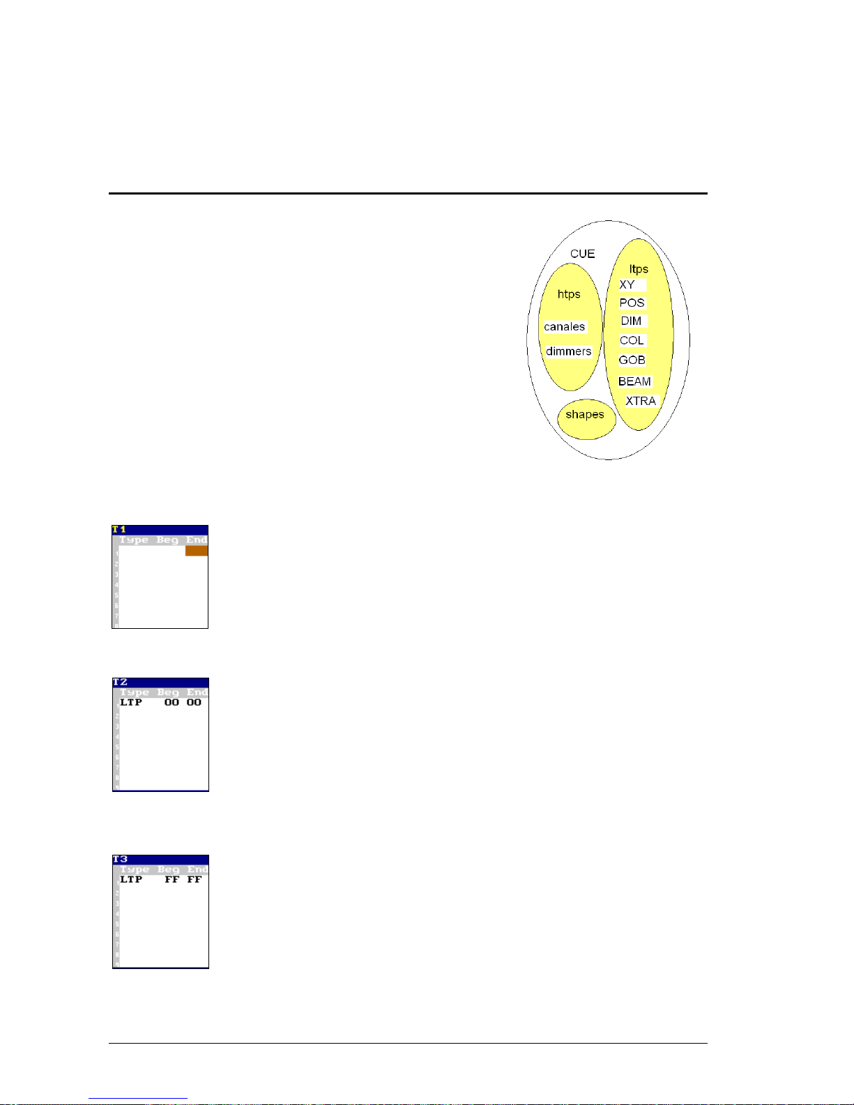
6-10 CUES & GROUPS
6.3 TIMING
The console has 6 different timings (T1 to T6). The timing sets
the cue & group behavior in playbacks.
At any moment, the cue timing can be edited.
Groups answer to the default timing.
The timing divides the cue (or group) contents in accordance
with the item types (htps, ltps, channels, gobos, colors, etc.)
with the objective that each items type goes in scene, fading or
not, in the desired moment.
When timing is applied to a cue (or group), its behavior
depends of the timing and of the own cue (or group). For
example, the timing 2 (T2) forces the ltps to jumps in scene
just when the master is activated.
About the timings definition (menu 06: Define Timings):
T1:
The contents, of cue or group, fade in accordance with the fade-in time
programmed (or fader movement), as a whole; there are not separations. As
unique exception, only the NO FADE parameters jump to their target values.
T1 is the timing by default, timing that always is applied after a system Reset.
T2:
The contents, of cue or group, fade in accordance with the fade-in time
programmed (or fader movement), except:
ltps (
1
) that are forced to jump in scene at the beginning of the master travel
(Beg=00). They jump in scene because End = Beg
Use T2 to avoid ltps fade in scene, jumping to their target values at the
beginning of the master travel.
T3:
The contents, of cue or group, fade in accordance with the fade-in time
programmed (or fader movement), except:
ltps (
1
) that are forced to jump in scene at the end of the master travel
(Beg=FF). They jump in scene because End = Beg
Use T3 to avoid ltps fade in scene, jumping to their target values at the end of
the master travel.
LEVITON 8700 SERIES
Page 65
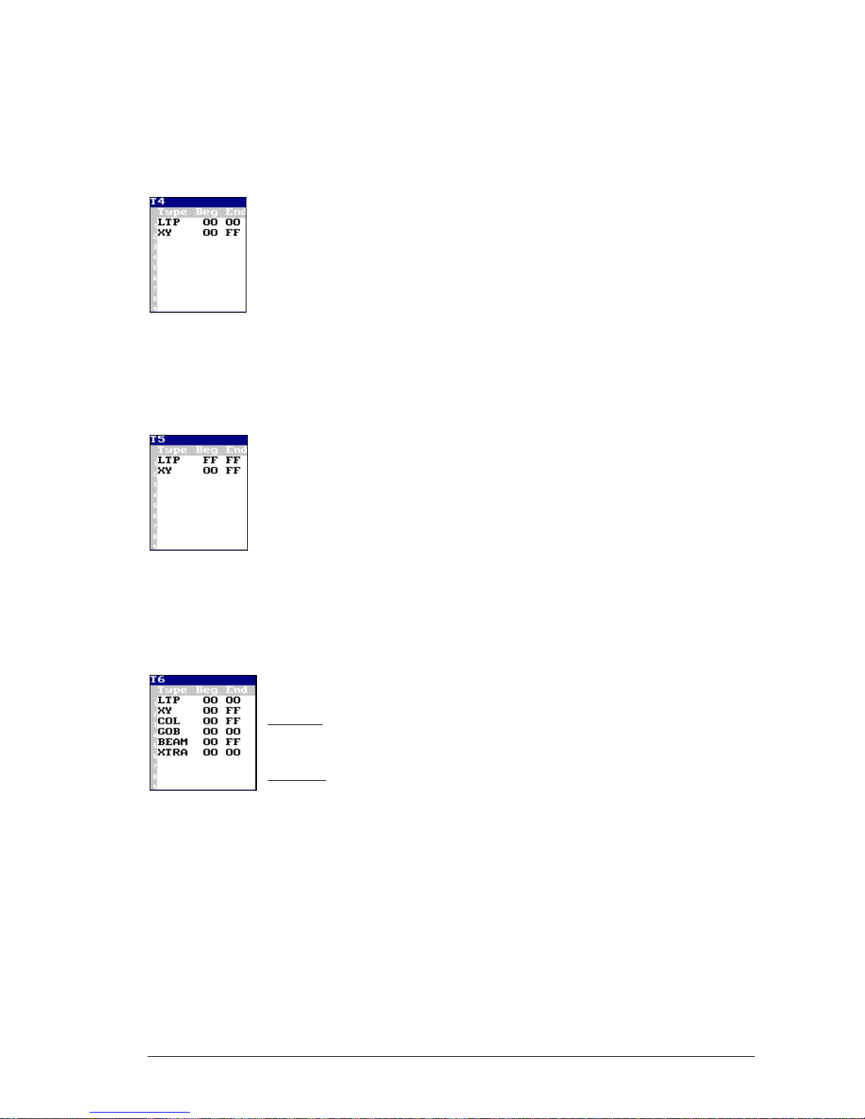
CUES & GROUPS 6-11
T4:
The contents, of cue or group, fade in accordance with the fade-in time
programmed (or fader movement), except:
ltps (
1
) that are forced to jump in scene at the beginning of the master travel
(Beg=00). They jump in scene because End = Beg
X & Y parameters (
2
) that are forced to fade in scene at the beginning of the
master travel (Beg=00). Their fading begins in 00 and ends in FF.
Use T4 to avoid ltps fade in scene, jumping to their target values at the beginning of the master
travel; except X & Y that fades in the fade-in time or in accordance with the fader movement.
This timing is similar to T2, but permits to control the change of one position to other.
T5:
The contents, of cue or group, fade in accordance with the fade-in time
programmed (or fader movement), except:
ltps (
1
) that are forced to jump in scene at the end of the master travel
(Beg=FF). They jump in scene because End = Beg
X & Y parameters (
2
) that are forced to fade in scene at the beginning of the
master travel (Beg=00). Their fading begins in 00 and ends in FF.
Use T5 to avoid ltps fade in scene, jumping to their target values at the end of the master travel;
except X & Y that fades in the fade-in time or in accordance with the fader movement. This
timing is similar to T3, but permits to control the change of one position to other.
T6:
The contents, of cue or group, fade in accordance with the fade-in time
programmed (or fader movement)...
Included:
X & Y parameters (
2
), COL parameters (3) & BEAM parameters (
5
):
Where Beg=00 & End=FF.
Excluded:
The rest of the ltps (1), GOB (4) and XTRA (
6
) are forced to jump in scene at
the beginning of the master travel (Beg=00). They jump in scene because End = Beg
Use T6 to avoid ltps, especially GOB y XTRA, fade in scene, jumping to their target values at
the beginning of the master travel. Permits that COL, BEAM, X & Y parameters fade in scene in
accordance with the fade-in time or the fader movement.
This timing is very used to divide a cue in these 6 basic types…
LEVITON 8700 SERIES
Page 66
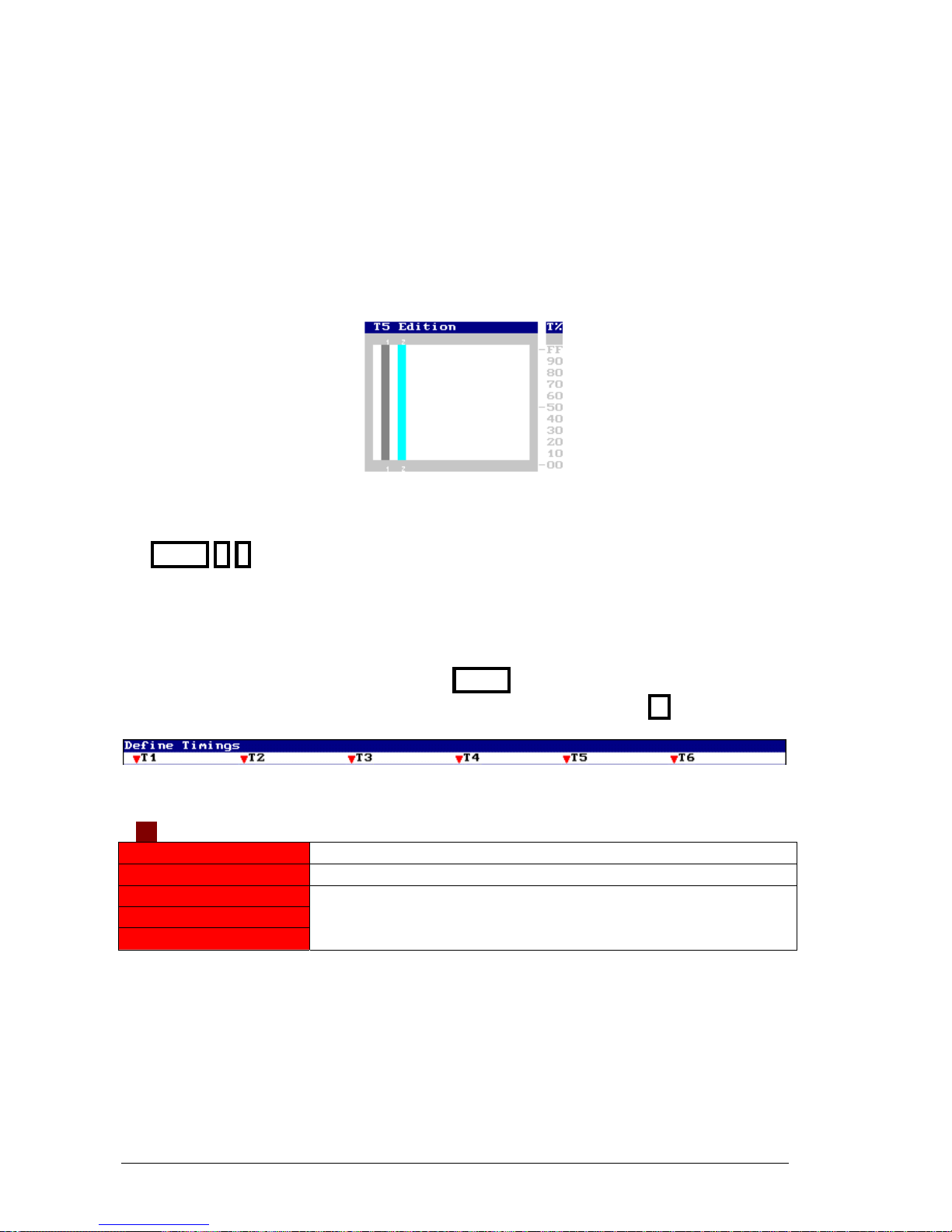
6-12 CUES & GROUPS
Graphically:
The time, in which a type is activated, Beg, equivalent to a T↑, is represented with a gray bar if
greater than 00.
The fading of each type, End - Beg, equivalent to a T↑, is represented with a cyan bar if greater
than 00.
Example for T5:
The timings are edited in the menu 06: Define Timings.
MENU 0 6
This screen has 2 zones:
• Setup line.
• Edition table.
Toggle between these zones using the mouse or MENU.
Also, from the Setup line, it’s possible to change to the edition table pressing
In the Setup line, select the desired timing (T1 a T6), in example T2, for:
T2
0: Set Default
Set T2 as default timing to be associated to new cues
1: Restore
Restore the initial values programmed in T2
2: Test Slow
3: Test Middle
4: Test Fast
These options permit us to do a dynamic test of the T2 behavior.
This test is showed dynamically in the Test window. The test can be
Slow, Middle or Fast.
LEVITON 8700 SERIES
Page 67
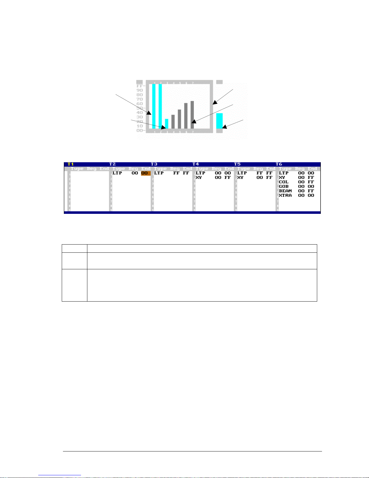
CUES & GROUPS 6-13
In Test window, dynamically, it’s possible to observe:
Status of the timing parts at this moment.
Part completely in scene
Part computing a wait-in time.
Part fades in scene.
T
est progress, currently at 40%.
To edit timing, toggle to the edition table:
Timing is divided in several parts (maximum 9), and each part is defined as:
Type
The items type that are grouped in this part (htps, ltps, colors...)
Beg
Begin: The point where the fading of this part must be started. This point is edited
as percentage (0-100%) of the cue fade-in time and is equivalent to a T↑
End
End: The point where the fading of this part must be ended. This point is edited as
percentage (0-100%) of the cue fade-in time. The End value must be equal or greater
that the begin value. If Begin=End the part jumps in scene (equivalent to a T↑=
0.1)
About the items type, always the more detailed Type has the priority. In example, if a part is
defined as HTP and other part as Dimm (that also is htp), the dimmers are placed in the Dimm
part that has the priority.
In concrete, this situation is between the types:
HTP & Dimm/CHAN
LTP & XY/POS/DIM/COL/GOB/BEAM/XTRA
POS & XY
LEVITON 8700 SERIES
Page 68
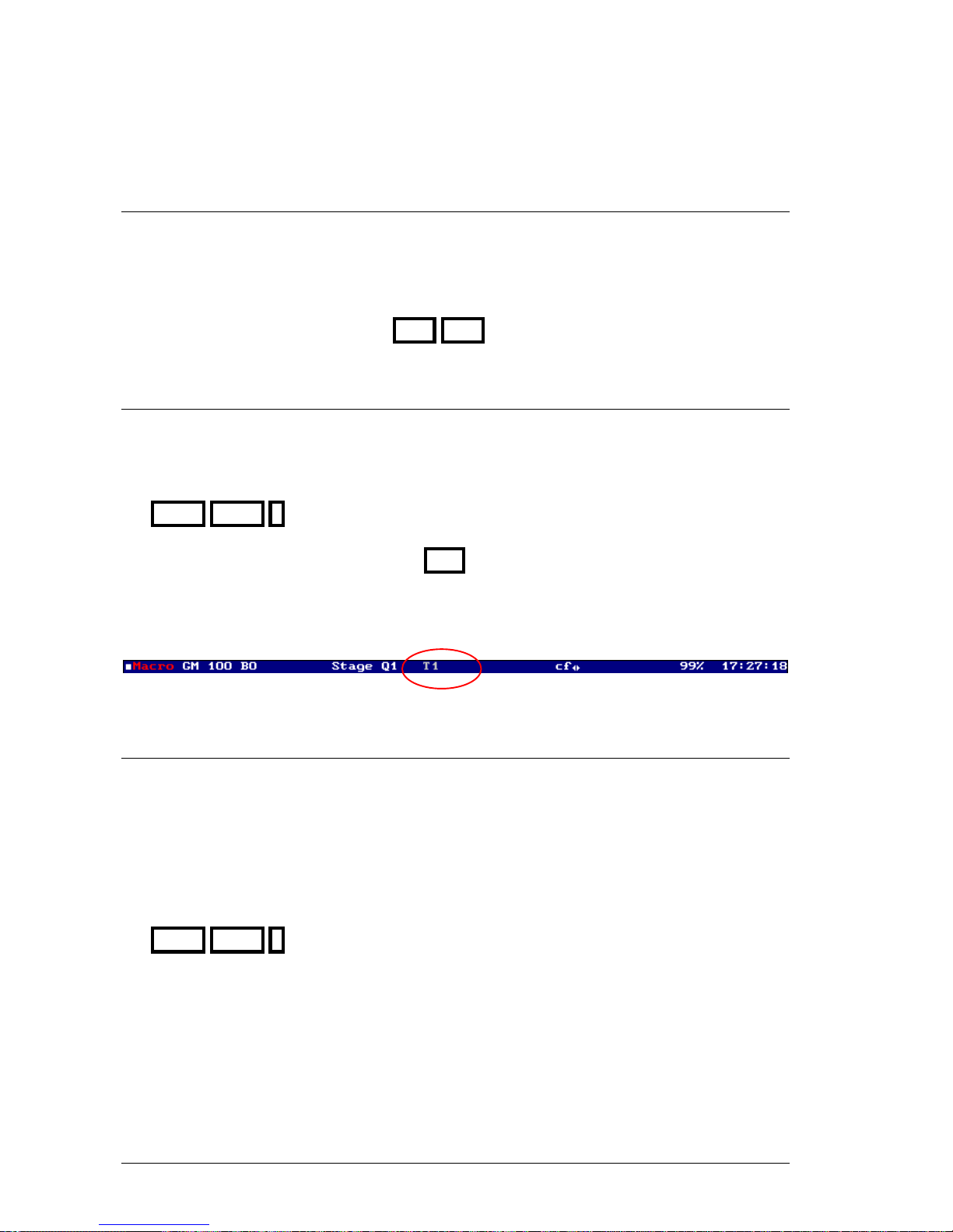
6-14 CUES & GROUPS
6.3.1 SET THE DEFAULT TIMING
The default timing is the timing associated to each new cue if other timing isn’t specified.
There are 3 ways to set up the default timing:
• From the Setup line of the menu 06: Define Timings
• From the Timing option of the menu 30: Editor & Times
• From the Setup line of the cue list, CUE CUE
6.3.2 EDITION OF THE CUE TIMING
The cue timing (T1 to T6) can be edited from the editor or from the cue list.
From the editor:
When a cue is being edited, it’s possible to change its timing pressing:
PART PART # Where # is the desired timing number.
The selected timing stays in the editor, until RST is pressed (returning to the default timing).
In the system status line the active timing is showed. If the active timing is the default timing,
this appears in gray color:
6.3.3 CONVERT TIMINGS TO CUES PARTS
It’s possible to personalize a cue with an associated timing, editing the timing values as cue parts
that can be edited manually (items and times).
The cue parts also can be created in the editor (manually).
A cue with parts hasn’t timing. Editing it timing, the parts are overwritten.
A cue with timing hasn’t parts. Editing parts, the timing is overwritten.
Editing a cue, it’s possible to convert its timing values to cue parts (editables), pressing:
PART PART 7 {to select the option 7:TO PART}
Note that in the system status line, the timing flag (in example T3) is overwritten with a parts
flag: P
Timing and cue parts have the same structure, and only timing or only parts can be actives in a
cue.
LEVITON 8700 SERIES
Page 69
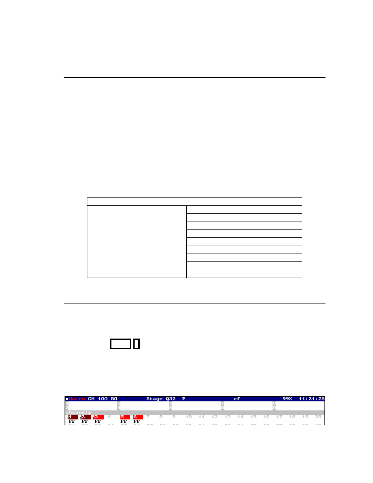
CUES & GROUPS 6-15
6.4 CUE PARTS
One cue can have 9 parts in addition to the base cue. Each part can have its contents and times
(T↑ and T↑) with values totally free.
The cue parts permit us that the cue items fade-in scene with different speeds, speeds controlled
for the cue times and the parts times, similar to the timing, but with absolutes values for contents
and times.
Each channel and parameter stored in the cue can be controlled for the times of the base cue
(P0) or for the times of one cue part (P1 to P9).
For that one part exists, must have at least one channel or parameter.
The base cue exists always including if it’s empty.
In resume, one cue can be divided in:
CUE
Part 1 (optional) + input times
Part 2 (optional) + input times
Part 3 (optional) + input times
Part 4 (optional) + input times
Part 5 (optional) + input times
Part 6 (optional) + input times
Part 7 (optional) + input times
Part 8 (optional) + input times
Base cue = Part 0
+ Times of input, output and wait
+ Text
+Jump
+ Command
Part 9 (optional) + input times
6.4.1 EDITION OF PARTS
The parts can be edited when the cue is been edited or modifying the cue to divide it in parts. In
both cases, the same method is used:
To include channels and/or parameters in a part, select them and press:
{Selection} PART # Where # is the part number (1 to 9).
Repeat this step as many times as necessary.
The auxiliary screen presents near each item its part number. Note that the timing flag is
overwritten with the parts flag (P) in the status line.
LEVITON 8700 SERIES
Page 70
6-16 CUES & GROUPS
Edit the cue 10 including the channels 1 to 10 at 50%, the part 1 including the channels
11 to 12 at 35%
RST Empty the editor if is needed
CHANNEL 1 THRU 1 0 @ 5 0 Edition of the channels 1 to 10
1 1 THRU 1 2 @ 3 5 PART 1 Edition of the part 1
CUE 1 0 REC And store the editor as cue 10
Modify the cue 10 (of the previous example) including the channel 1 in part 1, changing
the channel 12 from part 1 to the 2, and adding the channel 15 at 80% in part 3.
RST CUE 1 0 MDFY Select the cue 10 to modify it
CHANNEL 1 PART 1 Set the channel 1 in part 1
1 2 PART 2 Set the channel 12 in part 2
1 5 @ 8 0 PART 3 Edit the part 3
REC And accept the modification of the cue 10
Use example of parts in Theater:
Suppose a scene with a slowly nightfall, where at the end of the nightfall a street lamp will be lit.
The street lamp is the channel 25, and the nightfall lights are the channels 10 to 15.
Store these channels at full in the cue 1 and the channel 25 in the part 1
CHANNEL 1 0 THRU 1 5 ENTER 2 5 @ @ 2 5 PART 1 CUE 1 REC
Now, open CUE CUE screen to edit the cue 1 with T↑=35 sc and its part 1 with T↑ = 35
& T↑=0,1 seconds.
In this way, when the cue 1 fades in scene, all these channels fades in scene, slowly, except the
channel 25 (street lamp) that waits 35 seconds and then fades in scene in a cut time.
In the next scene dawns slowly, and after the dawn the street lamp will be at off. The dawn is
done using the channels 30 to 40, and the street lamp is the channel 25.
CHANNEL 3 0 THRU 4 0 @ @ 2 5 @ 0 1 PART 1 CUE 2 REC
Edit the cue 2 with T↑=10 sc, and its part with times as T↑ =0,1 & T↑= 10 seconds.
Note: Example of cue 2 is done using a dipless crossfade in mode T↑
(See option Dipless Mode inside menu 31: Playbacks)
LEVITON 8700 SERIES
Page 71
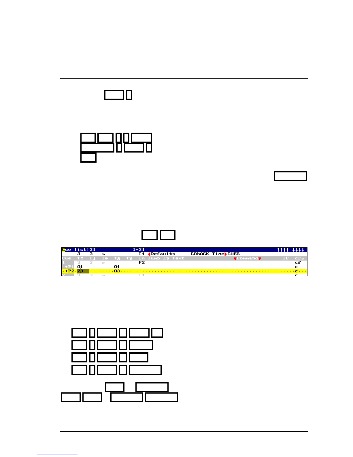
CUES & GROUPS 6-17
6.4.2 RETURN A ITEM TO THE BASE CUE
To return channels, scrollers, or parameters in a part, to the base cue, select them and press:
{Selection} PART 0
If all the items of one part are eliminated, the part is deleted.
In the cue 10, return the channel 1 to the base cue.
RST CUE 1 0 MDFY Select the cue 10 to modify it
CHANNEL 1 PART 0 Set the channel 1 in the base cue (part 0)
REC And accept the modification of the cue 10
Remember: To delete an item of one cue (is or not in a part) use the RELEASE
function.
6.4.3 EDIT TIMES FOR THE CUE PARTS
Each cue part can have programmed its input times: T↑ and T↑
To edit these input times, press CUE CUE
The times of each part are presented in one line (T↑ & T↑ ). To edit one of these times, select it
and enter its value. In this example, the cue 1 has 2 parts (+P1 & +P2).
6.4.4 OTHERS ACTIONS WITH PARTS
CUE # PART #’ LOAD M# Loads in M#, the part #’ of the cue #
CUE # PART #’ ENTER Selects in the editor the part #’ of the cue #
CUE # PART #’ CALL Call in the editor the part #’ of the cue #
CUE # PART #’ RELEASE Releases of the editor the part #’ of the cue #
Remember that CALL & RELEASE execute these commands fading in 2 seconds; and
CALL CALL & RELEASE RELEASE execute these commands suddenly.
LEVITON 8700 SERIES
Page 72
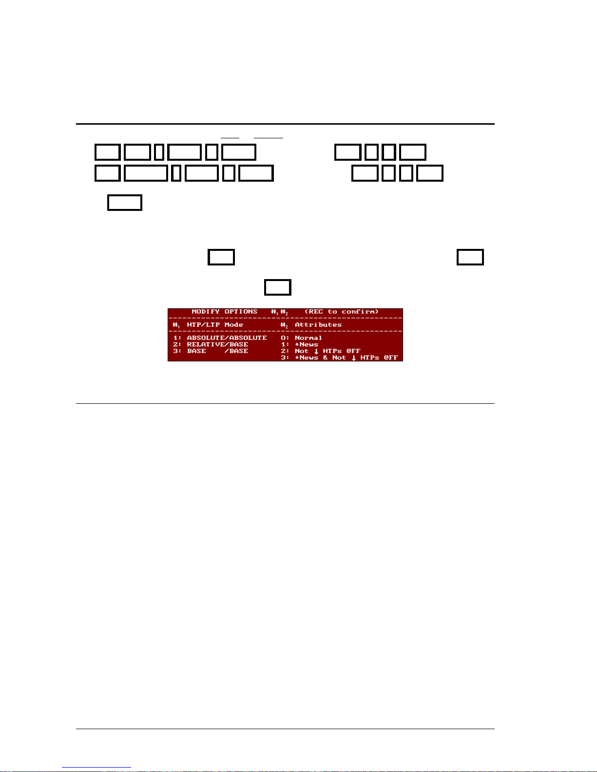
6-18 CUES & GROUPS
6.5 MODIFY A RANGE OF CUES OR GROUPS
It’s possible to modify a range of cues or groups.
RST CUE # THRU #’ MDFY {modifications} REC #
1 #2
REC
RST GROUP # THRU #’ MDFY {modifications} REC #
1 #2
REC
When MDFY is pressed, only the first cue (or group) of the selected range is loaded in the
editor to modify it. In the status line appears the flag Modify CUEs (or Modify GRPs) in a
red filed.
After the modifications, press REC to store them over all the cues of the range. When REC is
pressed, red window appears with the options of mode (#1) and attribute (#
2
). After that the
options #1 and #2 have been entered, press REC again to modify the range.
6.5.1 The mode options (#
1
)
1: ABSOLUTE/ABSOLUTE
The modifications are applied to the range cues in absolute mode. So, the editor value is the
value to apply in the modifications.
2: RELATIVE/BASE
HTP=RELATIVE: Mode where each value that has been modified, takes the relative
value for the modification. Example: If a channel modifies its level from 45 to 50%,
relative value +5%, in all the cues this channel increments its level in 5%.
LTP=BASE: The parameters modifications are applied to the range cues in absolute
mode only in case of that the source value coincide with the value of the first cue before
the modification. Example, if a color parameter is modified from Red to Green, in the
rest of the range cues only when this parameter is at Red will be modified to Green.
3: BASE/BASE
The modifications are applied to the range cues in absolute mode only in case of that the source
value coincides with the value of the first cue before the modification.
Examples of modification for a cues range:
LEVITON 8700 SERIES
Page 73
CUES & GROUPS 6-19
Modification: Channel 1@60 Fixture 1 red
Mode 1: ABSOLUTE/ABSOLUTE
CUE 1 TRHU 3 MDFY {modifications} REC 1 0 REC
Cue Source cue Modified cue
1 Channel 1@50 2@30, Fixture 1 Blue Channel 1@60 2@30, Fixture 1 red
2 Channel 1@60 2@30, Fixture 1 Yellow Channel 1@60 2@30, Fixture 1 red
3 Channel 1@30 Fixture 1 Blue Channel 1@60, Fixture 1 red
Modification: Channel 1@60 (+10%) Fixture 1 red (from Blue a red)
Mode 2: RELATIVE/BASE
CUE 1 TRHU 3 MDFY {modifications} REC 2 0 REC
Cue Source cue Modified cue
1 Channel 1@50 2@30, Fixture 1 Blue Channel 1@60 2@30, Fixture 1 red
2 Channel 1@60 2@30, Fixture 1 Yellow Channel 1@70 2@30, Fixture 1 Yellow
3 Channel 1@30 Fixture 1 Blue Channel 1@40, Fixture 1 red
Modification: Channel 1@60 (de 50% a 60%) Fixture 1 red (from Blue a red)
Mode 3: BASE/BASE
CUE 1 TRHU 3 MDFY {modifications} REC 3 0 REC
Cue Source cue Modified cue
1 Channel 1@50 2@30, Fixture 1 blue Channel 1@60 2@30, Fixture 1 red
2 Channel 1@60 2@30, Fixture 1 yellow Channel 1@60 2@30, Fixture 1 yellow
3 Channel 1@30 Fixture 1 blue Channel 1@30, Fixture 1 red
6.5.2 The attribute options (#
2
)
0: Normal
The modification of an item only is applied in the cues where this item exists.
1: +News
The modification of an item is applied always; in the cues where this item doesn’t exist the item is
added.
2: Not ↓ HTPs @FF
The modification of an item only is applied in the cues where this item exists, except when this
item is a channel or dimmer at FF (100%).
3: + News & Not ↓ HTPs @FF
The modification of an item is applied always; except when this item is a channel or dimmer at
FF (100%). In the cues where this item doesn’t exist the item is added.
LEVITON 8700 SERIES
Page 74
6-20 CUES & GROUPS
Examples of modification for a cues range:
All the modifications are done in mode 1: ABSOLUTE/ABSOLUTE
Modifications: CHANNEL 1 @ 6 0 2 @ 5 0 REC 1 0 REC
Attribute 0: Normal
Cue Source cue Modified cue
1 channel 1@ 50, channel 2 @ 30 channel 1@ 60, channel 2 @ 50
2 channel 1@ 60, channel 2 @ 30 channel 1@ 60, channel 2 @ 50
3 channel 1@ FF channel 1@ 60
Modifications: CHANNEL 1 @ 6 0 2 @ 5 0 REC 1 1 REC
Attribute 1: +News
Cue Source cue Modified cue
1 channel 1@ 50, channel 2 @ 30 channel 1@ 60, channel 2 @ 50
2 channel 1@ 60, channel 2 @ 30 channel 1@ 60, channel 2 @ 50
3 channel 1@ FF channel 1@ 60, channel 2 @ 50
Modifications: CHANNEL 1 @ 6 0 2 @ 5 0 REC 1 2 REC
Attribute 2: Not ↓ HTPs @FF
Cue Source cue Modified cue
1 channel 1@ 50, channel 2 @ 30 channel 1@ 60, channel 2 @ 50
2 channel 1@ 60, channel 2 @ 30 channel 1@ 60, channel 2 @ 50
3 channel 1@ FF channel 1@ FF
Modifications: CHANNEL 1 @ 6 0 2 @ 5 0 REC 1 3 REC
Attribute 3: + News & Not ↓ HTPs @ FF
Cue Source cue Modified cue
1 channel 1@ 50, channel 2 @ 30 channel 1@ 60, channel 2 @ 50
2 channel 1@ 60, channel 2 @ 30 channel 1@ 60, channel 2 @ 50
3 channel 1@ FF channel 1@ FF, channel 2 @ 50
The exam screen of channels and fixtures (for example CHANNEL # EXAM) is used
to exam the result of these range modifications.
LEVITON 8700 SERIES
Page 75
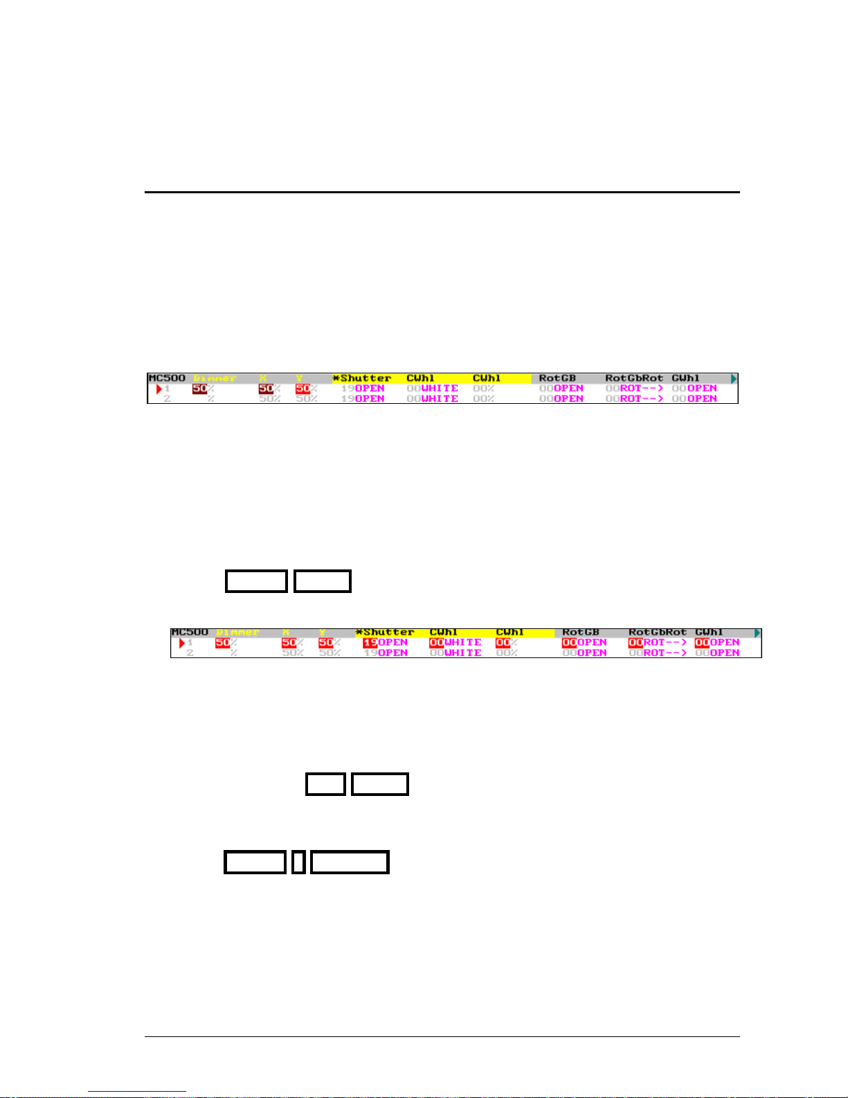
CUES & GROUPS 6-21
6.6 THE FIXTURES IN CUES & GROUPS
The fixture parameters that are in scene in tracking mode or controlled by some playback, affect
to the scene but they are not included in the cue (or group) if they are not in the editor (red or
light red).
This characteristic permits us to store the cues (or groups) in several modes, depending of the
result that we want to obtain. Some examples:
Starting with empty editor. Select the fixture 1, edit its dimmer and position, and from here, there
are several possibilities:
• Store a cue. This cue only has the X, Y and Dimmer parameters of the fixture 1. When this
cue is executed from a master or crossfade, it’s possible to control the color (Cwhl,...) or
gobo (RotGB...), etc, of the fixture 1 with other master or crossfade.
This mode is used to store cues that will be executed sequentially, storing only the changes
from current cues to the next cue.
• Store a cue including the current values in scene of the color, gobo, etc, of the fixture 1,
pressing PARAM ENTER. When this cue is executed from a master or crossfade, all the
fixture parameters are controlled.
This mode is very interesting for the first cue of a crossfaders, or when the cue will be
executed in a master to set a whole scene.
It’s possible to store a cue including any parameters type, for example including the gobo
parameters, pressing: GOB ENTER
Also it’s possible to exclude any parameter or type of the editor before to store the cue to
avoid that they be stored in the cue. In example, to store the cue without the Dimmer,
pressing PARAM 1 RELEASE
LEVITON 8700 SERIES
Page 76

6-22 CUES & GROUPS
RESUME
STORE CUES OR GROUPS:
A cue // group {editor}CUE # REC // {editor/selection} GROUP # REC
The next cue // group {editor}CUE REC // {editor}REC
The next group in a master {editor/selection} GROUP REC //{editor/selection}LOAD M#
Store the scene in the next cue: CALL REC
Modifications:
General: CUE CUE // GROUP GROUP
Contents: RST CUE # MDFY {modifications} REC
RST GROUP # MDFY {modifications} REC
RST MDFY M# {modifications} REC
{modifications} MDFY M#
RST CUE # THRU #’ MDFY {modifications} REC #1 #2 REC
RST GROUP # THRU #’ MDFY {modifications} REC #1 #2 REC
Exam cues or groups:
The list: CUE EXAM // GROUP EXAM
A cue or group: CUE # EXAM // GROUP # EXAM
A channel in cues & groups: CHANNEL # EXAM
A fixture in cues & groups: FIXTURE # EXAM
Delete:
A cue or group: CUE # DELETE // GROUP # DELETE
A range: CUE # THRU #’ DELETE // GROUP # THRU #’ DELETE
All the cues or groups: CUE DELETE // GROUP DELETE
Copy & exchange (examples for cues):
Copy: CUE # (THRU #’) COPY #’’ ENTER
Exchange: CUE # (THRU #’) COPY COPY #’’ ENTER
Selection:
A cue or group: CUE # ENTER // GROUP # ENTER
A range: CUE # THRU #’ ENTER // GROUP # THRU #’ ENTER
The master content: ENTER M#
The masters contents: ENTER M# M# M# ... ENTER
The scene: ENTER ENTER
Call:
A cue or group: CUE # CALL (CALL) // GROUP # CALL (CALL)
A range: CUE # THRU #’ CALL (CALL) // GROUP # THRU #’ CALL (CALL)
Several masters: CALL M# // CALL M# M# M# ... CALL
Scene: CALL CALL
Call to channels & parameters of a cue or group (examples for cues):
CUE # CHANNEL #’ CALL (CALL)
CUE # FIXTURE #’ (PARAM #’’) CALL (CALL)
LEVITON 8700 SERIES
Page 77

CUES & GROUPS 6-23
Parts & timings in the editor
Edition: {selection } PART # ... {selection } PART #’
Deleting: {selection} PART 0
Edit with Timing #: {editor} PART PART #
Convert timing to Parts: {editor} PART PART 7
Commands that use parts:
CUE # PART #’ ENTER
CUE # PART #’ CALL (CALL)
CUE # PART #’ LOAD M#
CUE # PART #’ RELEASE
LEVITON 8700 SERIES
Page 78

6-24 CUES & GROUPS
LEVITON 8700 SERIES
Page 79
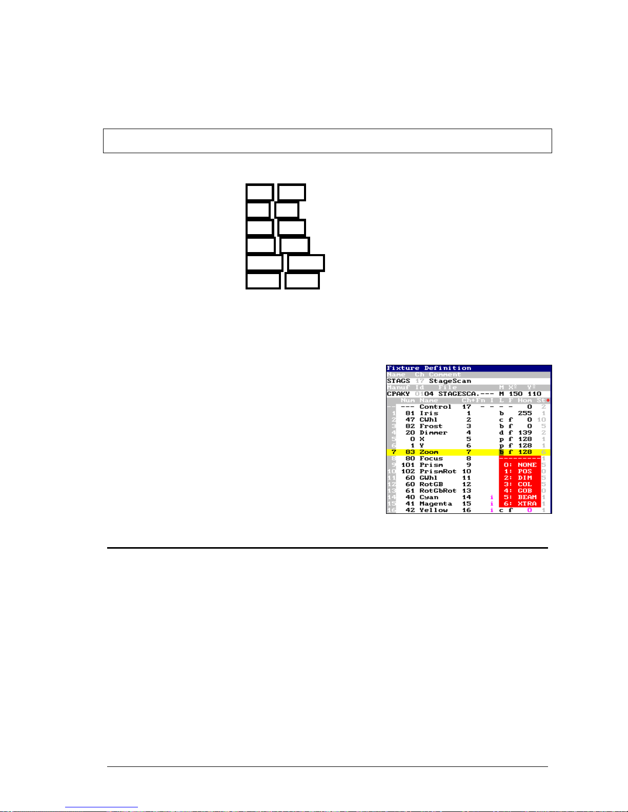
7. LIBRARIES
The 8700 Series consoles have 6 library categories:
99 libraries of position - POS POS
99 libraries of dimmer - DIM DIM
99 libraries of color - COL COL
99 libraries of gobos - GOB GOB
99 libraries of beam - BEAM BEAM
99 libraries of x-tra - XTRA XTRA
When cues and groups are edited using library values, the edition is more conceptual, and their
modifications are easier. Suppose that several cues has been stored using the color library red, if
after it’s needed change this color in the show, will be enough to modify the color library red, for
that the whole show will be updated with the new color.
The library behavior depends of its category.
The fixture parameters that are included in each category
are defined (and can be edited) in each fixture definition,
inside the menu 04- Fixtures.
Then, the category of each parameter and if this is included
(or not) in the libraries is showed in the Fixture Definition
window, concretely in the L column.
7.1 POSITION LIBRARIES
The position libraries collect the positions used frequently in the show.
The position libraries are stored from the editor and take the values of the position parameters
(as X and Y) of all fixtures in the editor.
Each library can store the position of one, several or all the fixtures.
After, this position can be applied to one, several or all the fixtures stored in the library.
To store a position, select the desired fixtures and place their beams in the desired position (or
positions):
{fixture} TB {fixture} TB {fixture} TB ...
When all needed fixtures are edited, to store the position #, press:
LEVITON 8700 SERIES
Page 80
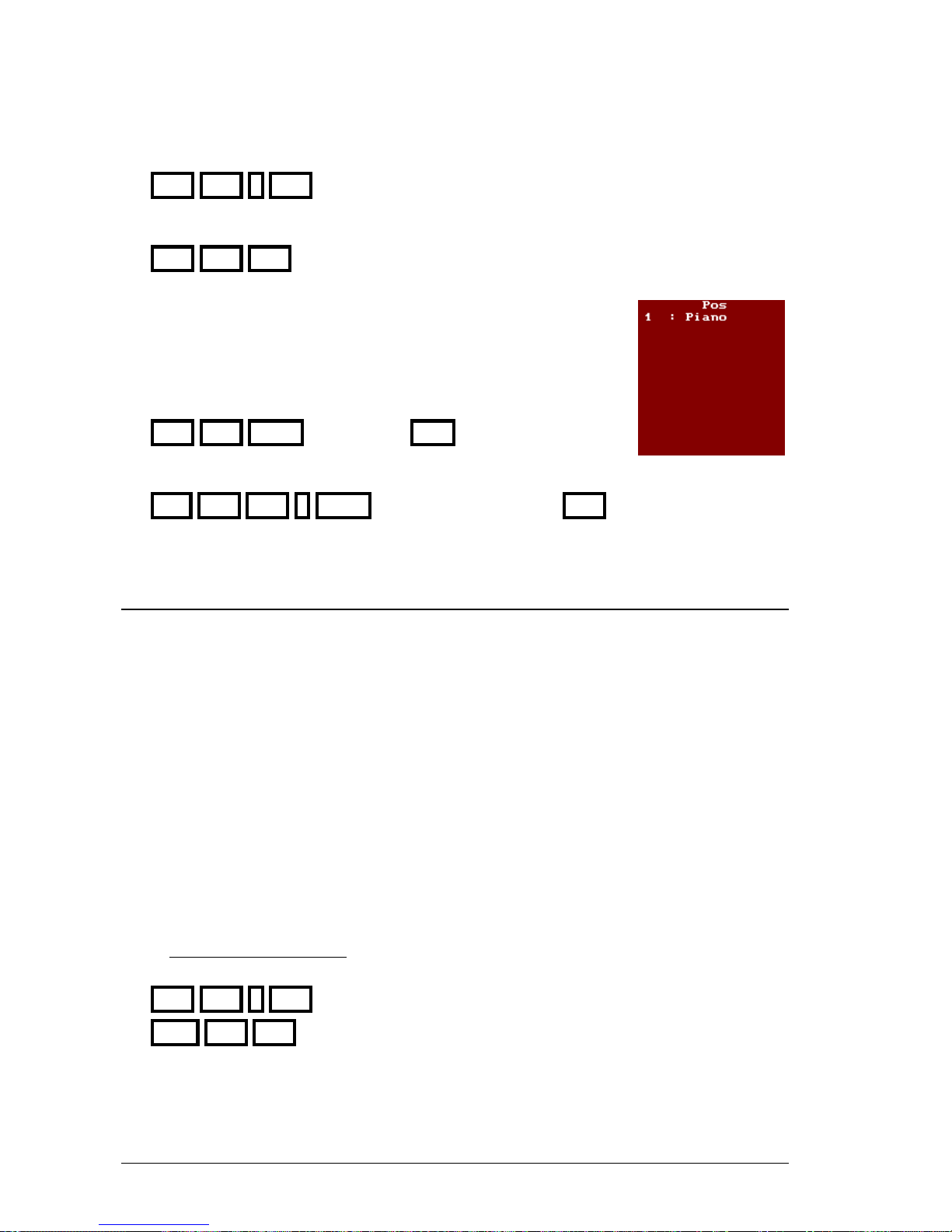
7-2 LIBRARIES
POS POS # REC
Or to store the next position, press:
POS POS REC
When POS POS is pressed, the system opens a selection window with
the positions list to help us to select the desired number. This window
has the numbers and texts of the position libraries. If needed, to page this
window use MONITOR
To associate a text to a position library press:
POS POS MDFY {text edition} EXIT
To modify a position and in this way, update all the cues and groups those use this position:
RST POS POS # MDFY {modifications in editor} REC
7.2 DIM, COL, GOB, BEAM & X-TRA LIBRARIES
These libraries collect parameters configurations of dimmer, colors, gobos, beam and x-tra,
frequently used, that can be used in cues & groups.
These libraries are stored in the editor, using the first fixture of each type; type that will be
included in the library. Each library can have information about one type, several or all the types
in the show. After these libraries can be applied to any stop of included type.
Example: The fixture 1 to 8 are MC504, the color for the fixture 1 is edited in the editor
and is stored as color library. Then, this color can be applied to any fixture from 1
to 8.
These 5 categories (dimmer, color, gobo, beam & x-tra) are stored, modified and applied in the
same way.
To store a library, for example of color:
Select
the first fixture of a type and edit the desired color (adjusting its color parameters). If
needed, repeat this step for each type to store in the library, and press:
COL COL # REC To store the color #
COL COL REC To store the next color
LEVITON 8700 SERIES
Page 81
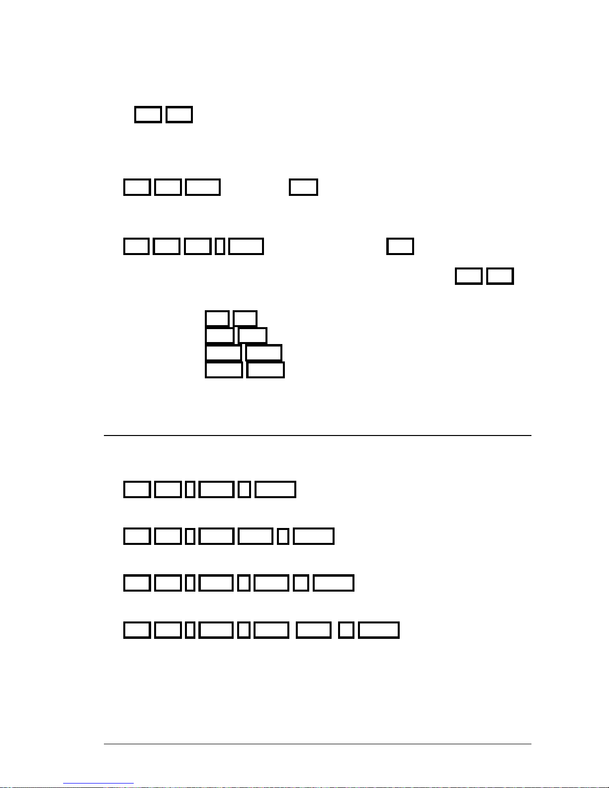
LIBRARIES 7-3
When COL COL is pressed, the system opens a selection window with the positions list to
help us to select the desired number. This window has the numbers and texts of the position
libraries. If needed, to page this window use MONITOR
To associate text to a library, for example of color, press:
COL COL MDFY {text edition} EXIT
To modify on these libraries, for example of color, (and with this update all the cues and groups
where the library is used), press:
RST COL COL # MDFY {modifications in editor} REC
These commands are the same for the rest of categories, only you must replace COL COL (of
color) for:
DIM DIM for dimmer,
GOB GOB for gobos,
BEAM BEAM for beam, and
X-TRA X-TRA for x-tras
7.3 COPY & EXCHANGE
The next commands can be applied to any library category.
Copy a library, for example of position, pressing:
POS POS # COPY #’ ENTER
Exchange 2 libraries, for example of position, pressing:
POS POS # COPY COPY #’ ENTER
Copy a libraries range, for example of position, pressing:
POS POS # THRU #’ COPY #’’ ENTER
Exchange 2 libraries ranges, for example of position, pressing:
POS POS # THRU #’ COPY COPY #’’ ENTER
LEVITON 8700 SERIES
Page 82
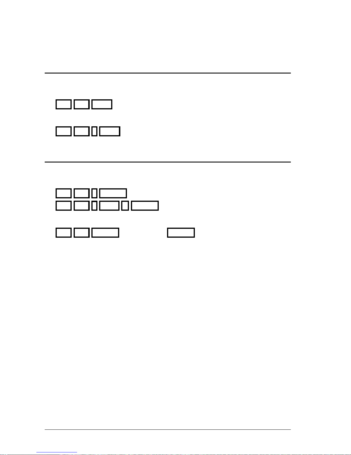
7-4 LIBRARIES
7.4 EXAM
The next commands can be applied to any library category
To exam the list of all the libraries, for example of position, press:
POS POS EXAM
To exam one library, for example one position, press:
POS POS # EXAM
7.5 DELETE
The next commands can be applied to any library category.
To delete a library or range, for example of positions, press:
POS POS # DELETE To delete the position #
POS POS # THRU #’ DELETE To delete the positions from # to #’
To delete all the libraries of one category, for example of position, press:
POS POS DELETE To confirm press DELETE
LEVITON 8700 SERIES
Page 83
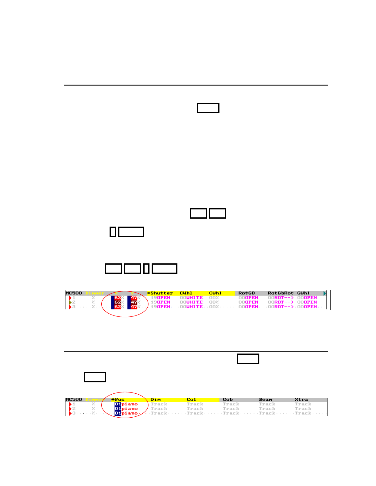
LIBRARIES 7-5
7.6 EDITING WITH LIBRARIES
To apply libraries in the editor, of any category, there are 3 methods that can be combined:
a) Numeric selection
b) Selection in control wheels (activated EDIT+)
c) Selections using the BANKS.
The libraries, always, are applied to the fixtures in the editor (if proceed) and over all the
parameters included in the library.
If, after a library is applied, a library parameter is modified, the library reference is losing,
remaining only the absolute values of these parameters in the editor.
7.6.1 NUMERIC SELECTION
Select the fixtures to apply the library, {fixtures}
Select the category of the library, for example, POS POS
Select the library number,
Pressing # ENTER
Or using the mouse #:Text.
Resume:
{fixtures} POS POS # ENTER
In the monitor, the parameter edited with library presents a blue character:
7.6.2 SELECTION IN CONTROL WHEELS
To take control of the libraries with the control wheels, activate EDIT+
When EDIT+ is activated, the fixtures present their categories and no their parameters. This
screen, more conceptual, is thought to edit directly with libraries & palettes.
Note that in this screen applied libraries are showed with its number in a blue field and its text.
LEVITON 8700 SERIES
Page 84
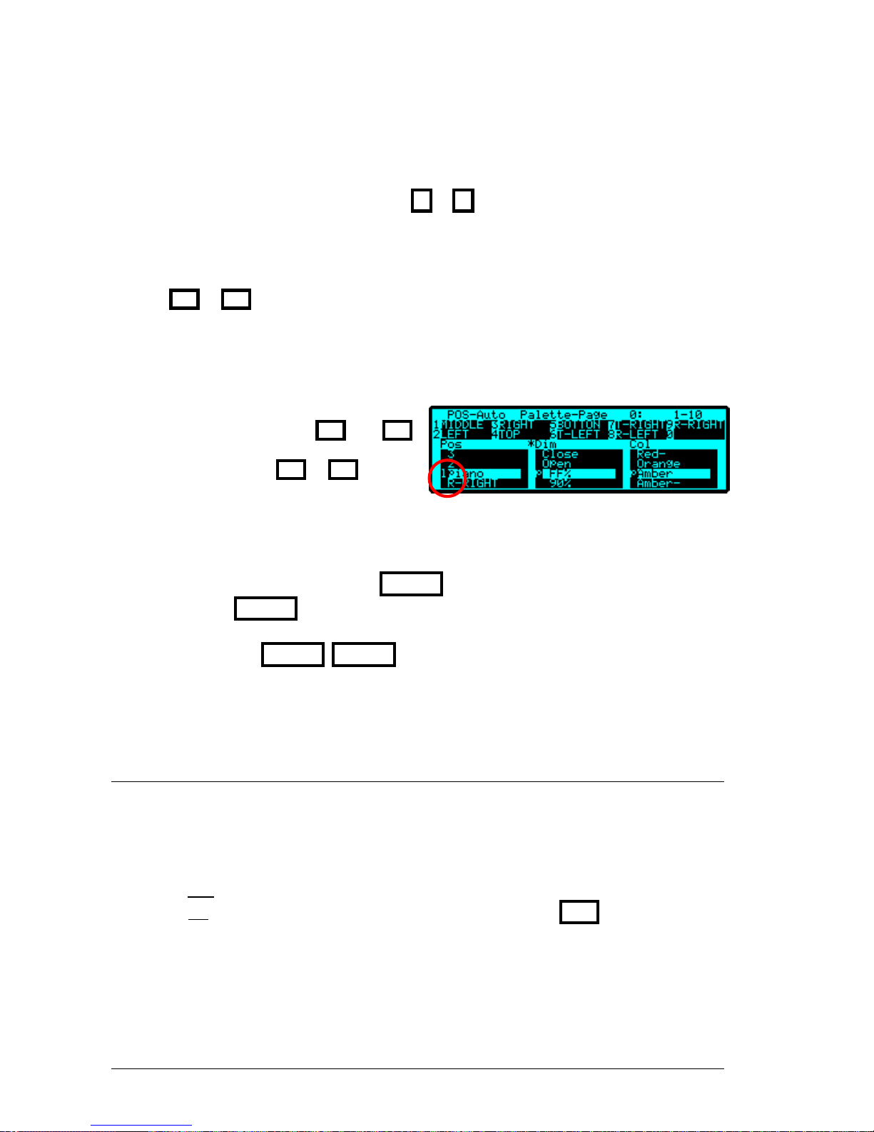
7-6 LIBRARIES
In this mode, the control wheels allow you to edit, directly, palettes & libraries of each category,
all organized in 2 banks that are paged pressing & .
In the Display (or touch panel for GX models), the contents of each wheel are presented, where:
Moving the wheels, W1, W2 & W3, you select the library/palette in continuous mode.
Pressing
or you select the library/palette of the active wheels (marked with a *).
Pressing in each wheel, W1, W2 y W3, you change the active wheel, marked with a *.
In each wheel, you have access to the palettes & libraries of the associated category. It’s
possible to scroll all the palettes (or libraries)
moving the wheel or pressing and ;
but to jump from palettes to libraries (or vice
versus) is needed to press or
In the display, if the selection is a palette, a p appears, and if is a library, a l appears.
If when the wheel is being moved, WHEEL is pressed; the edition is done in blind.
Only when WHEEL is released, the edited value is effective.
The command WHEEL WHEEL allows you to set the same value for the selected
fixtures, taking as reference the value of the first selected fixture, and avoiding the relative
difference between them.
7.6.3 SELECTION IN BANKS KEYS
BANKS allow you to execute macros directly when are configured as Auto or as one of the fixed
modes of category (POS, DIM, COL, GOB, BEAM, XTRA).
The mode of BANKS appears to the left of the status line, in example, to access to positions:
■POS in a blue field, if mode is POS
■POS in a red field, if mode is Auto. In AUTO mode is needed press POS to access to the
positions, since this configuration is interactive with the edition process.
LEVITON 8700 SERIES
Page 85
LIBRARIES 7-7
7.6.3.1. GX Models
If needed, configure the BANKS, in example for selections of positions:
BANKS 0 POS To set mode: Auto (POS)
BANKS 3 To set mode: POS.
Access to the desired palette (or library), paging BANKS with BANKS
In the touch panel there are the contents of the active page of the BANKS - 1B to 10
B
To select a library (or palette), is enough press:
#
B
If BANKS is set as Auto, but now aren’t as POS, to select a position, press:
POS #
B
Example, to select the position 1:Piano for the fixtures 1 & 3, press:
FIXTURE 1 FIXTURE 3 1
B
For BANKS in mode POS
FIXTURE 1 FIXTURE 3 POS 1
B
For BANKS in mode AUTO
7.6.3.2. GS and GL Models
If needed, configure the BANKS, in example for selections of positions:
BANKS 0 POS To set mode: Auto (POS)
BANKS 3 To set mode: POS.
Access to the desired palette (or library), paging BANKS with BANKS
In the display, under BANKS keys - 1
B
to 10B
B
B - you can see the active page and its contents.
To select a library (or palette), is enough press its associated key:
#
B
If BANKS is set as Auto, but now aren’t as POS, to select a position, press:
POS #
B
Example, to select the position 1:Piano for the fixtures 1 & 3, press:
FIXTURE 1 FIXTURE 3 1
B
For BANKS in mode POS
FIXTURE 1 FIXTURE 3 POS 1
B
For BANKS in mode AUTO
LEVITON 8700 SERIES
Page 86
7-8 LIBRARIES
7.6.3.3. General
A configuration very easy to edit with libraries & palettes is to configure the BANKS at
mode 2:GROUP and edit the palettes & libraries using the wheels, activating EDIT+. In this
mode, you can select the desired group and edit from the wheels with values of libraries and
palettes, repeating this process as many times as necessary.
Example
1B W1 W2 W3 Group 1 selection & edition of: position, dimmer and color.
5
B
W1 W3 Group 5 selection & edition of: position and color
9B W1 Group 9 selection & edition of gobo
Remember that:
1
B
is the same that GROUP 1 ENTER
1B 1B is the same that GROUP 1 CALL
LEVITON 8700 SERIES
Page 87

LIBRARIES 7-9
RESUME
Libraries of position, color, gobo beam or xtra (examples for positions)
Store a library: POS POS # REC
Select a library: POS POS # ENTER
Modify a library: POS POS # MDFY
Associate a text to a library: POS POS MDFY
Copy a library (or range): POS POS # (THRU #’) COPY #’’ ENTER
Exchange libraries (or ranges): POS POS # (THRU #’) COPY COPY #’’ ENTER
Exam a library: POS POS # EXAM
Exam the libraries list: POS POS EXAM
Delete a library (or range): POS POS # (THRU #’) DELETE
Delete all the libraries: POS POS DELETE
Edition of palettes & libraries using the control wheels:
EDIT+ W1, W2, W3
Edition of palettes & libraries using BANKS keys:
(POS) #
B
B
LEVITON 8700 SERIES
Page 88

7-10 LIBRARIES
LEVITON 8700 SERIES
Page 89
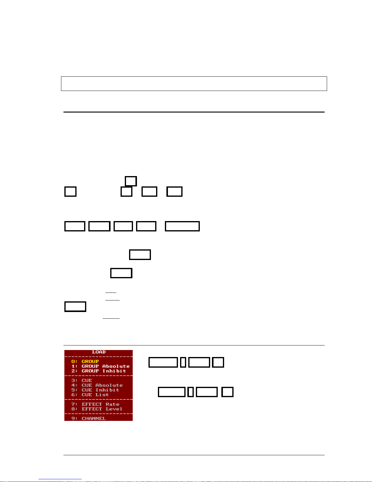
8. MASTERS AND PAGES
8.1 MASTERS
A master is a playback, and this playback can have:
• A Group (normal, Absolute or Inhibit)
• A Cue (normal, Absolute or Inhibit)
• A Cue List (See Chapter 10)
• An Effect with rate or level control (See Chapter 9)
• A Channel
Each master has a key M# and a fader M#
M# is any key from M1 to M24 or M48
M# is any fader from M1 to M24 or M48
There is a fader to control the masters output, SM, and some dedicated function keys, as:
FLMT, LOAD, PRIO , STEP & PAUSE_B
The first needed step is to load the items in each master:
{Select the item} LOAD {Select the option & master}
In general, when LOAD is pressed, an options window is opened. In this window:
The options in gray aren’t available for the current load.
The options in white are available for the current load. You can select some of them pressing
LOAD as many times as will be necessary or entering its index number (#), or using the mouse.
The option in yellow is the selected option.
8.1.1 LOADING GROUPS IN MASTERS
To load a group in master, normal mode, press:
GROUP # LOAD M#
Load the group 5 in master 8
GROUP 5 LOAD M8
LEVITON 8700 SERIES
Page 90

8-2 MASTERS AND PAGES
To load a groups range, in several masters, there are 2 options:
GROUP # LOAD T M# M# ... LOAD S
GROUP # THRU #’ LOAD M#
Load the groups 6, 7 & 8, in masters 6, 15 & 17
GROUP 6 LOAD T M6 M15 M17 LOAD S
Load the groups 1 to 5, in master 11 to 15
GROUP 1 THRU 5 LOAD M11
Loading ranges:
If the last group of the range is omitted, the console assumes that is the last stored.
Load from group 1 to last stored, in masters from 11:
GROUP 1 THRU LOAD M11
If the first and last groups of the range are omitted, the console assumes those are the first and
last stored respectively.
Load from first to last stored groups, in masters from 11:
GROUP THRU LOAD M11
To load groups range, using all masters from the master 1 and the selected group:
GROUP # LOAD FLMT
Remember. Also a master can be loaded with the editor content (avoiding the necessity of store it
previously). In this process, the system stores a new group with the editor content and loads it in
the selected master:
{edit or select channels and/or fixtures} LOAD M#
Load a new group in the master 14 with the channels from 1 to 5
CHANNEL 1 THRU 5 LOAD M14
A group, always, is loaded with its default fade time, Group/Ch T, and this time can be
changed in the menu 30 or in the masters edition page (see bellow). Groups adopt the behavior
of the timing by default.
LEVITON 8700 SERIES
Page 91
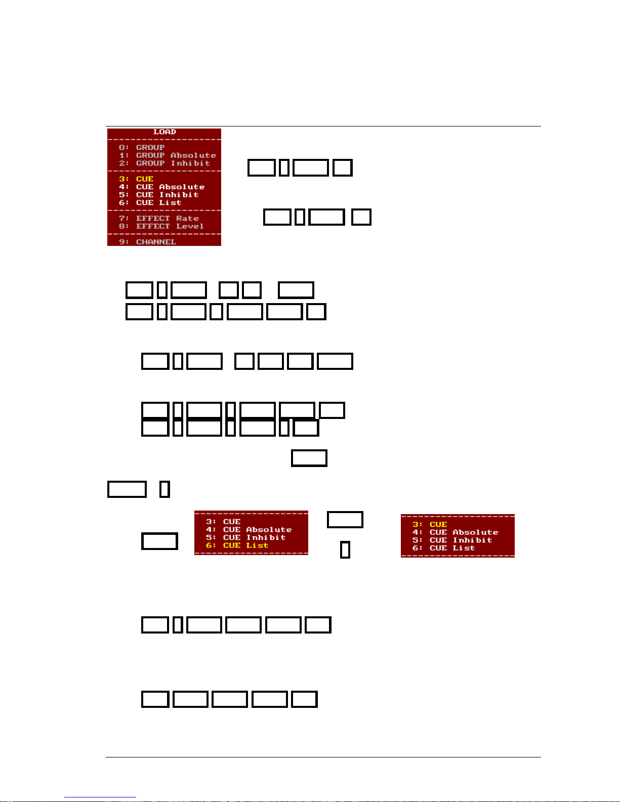
MASTERS AND PAGES 8-3
8.1.2 LOADING CUES IN MASTERS
To load a cue in master, normal mode, press:
CUE # LOAD M#
Load the cue 5 in master 8
CUE 5 LOAD M8
To load a cues range, in several masters, there are 2 options:
CUE # LOAD T M# M# ... LOAD S
CUE # THRU #’ LOAD LOAD M#
Load the cues 6, 7 & 8, in masters 6, 15 & 17
CUE 6 LOAD T M6 M15 M17 LOAD S
Load the cues 1 to 5, in master 11 to 15
CUE 1 THRU 5 LOAD LOAD M11 or
CUE 1 THRU 5 LOAD 3 M11
If the selection is a “cues range”. When LOAD is pressed, the selected option is 6: CUE List
(used to load the cues in only one master); the desired option is 3: CUE; select it pressing
LOAD or 3
LOAD
3:
LOAD
or
3
Loading ranges:
If the last cue of the range is omitted, the console assumes that is the last stored.
Load from cue 1 to last stored, in masters from 11:
CUE 1 THRU LOAD LOAD M11
If the first and last cues of the range are omitted, the console assumes those are the first and last
stored respectively.
Load from first to last stored cues, in masters from 11:
CUE THRU LOAD LOAD M11
LEVITON 8700 SERIES
Page 92
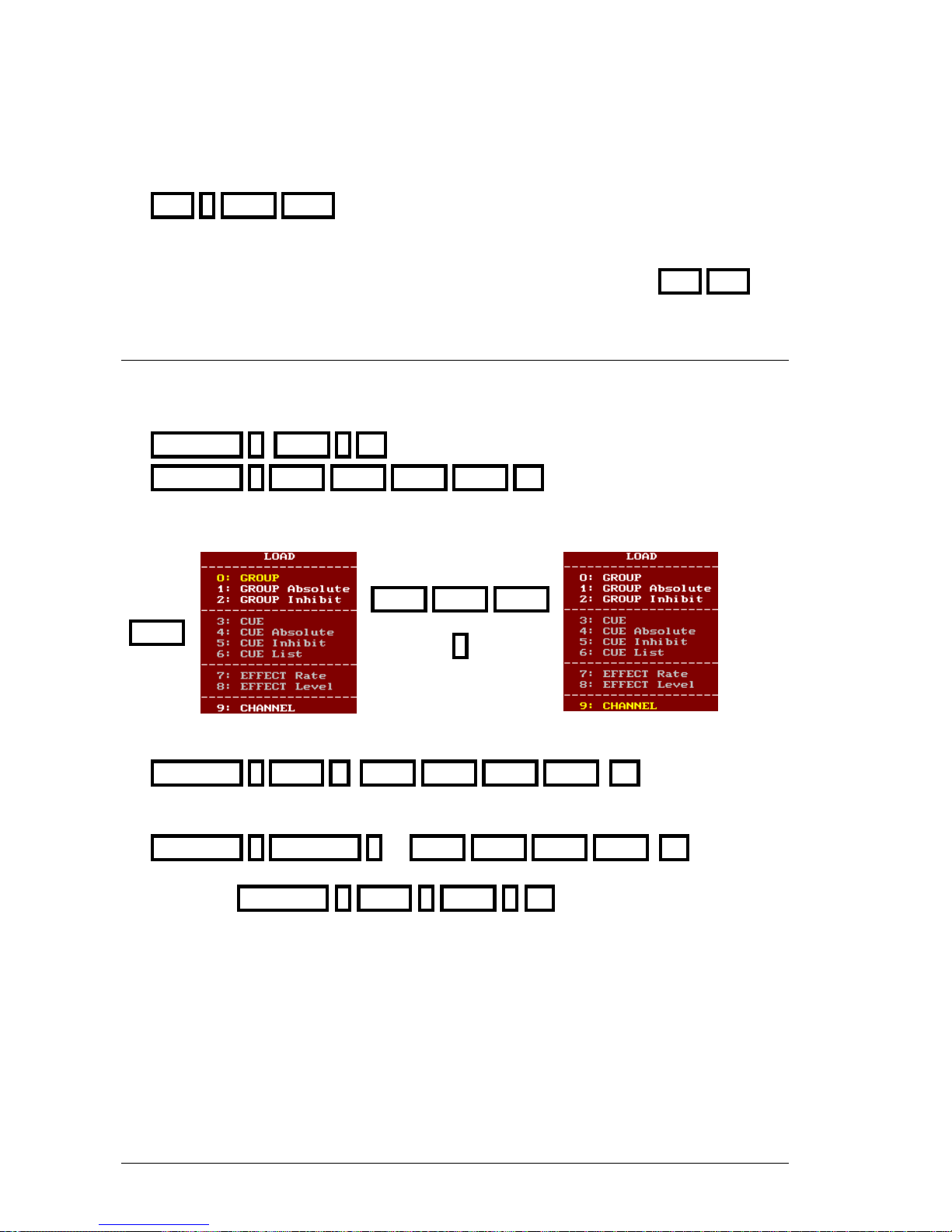
8-4 MASTERS AND PAGES
To load a cues range, using all masters, from the master 1 and the selected cue:
CUE # LOAD FLMT
Cues are loaded and controlled in accordance with their stored times, including their
timings or parts, and all these times can be changed in the edition page CUE CUE
8.1.3 LOADING CHANNELS IN MASTERS
A channel or channels can be loaded in masters as individual channels (no as group).
To load the channel # in master M#, press:
CHANNEL # LOAD 9 M# or
CHANNEL # LOAD LOAD LOAD LOAD M#
This process is done selecting the option 9: CHANNEL
LOAD
LOAD LOAD LOAD
or
9
or
9:Channel
To load a channels range in consecutive masters, from M#, press:
CHANNEL # THRU #’ LOAD LOAD LOAD LOAD M#
To load several channels, from M#, press:
CHANNEL # CHANNEL # … LOAD LOAD LOAD LOAD M#
Pressing CHANNEL 1 THRU 3 LOAD 9 M1, you load the channel 1 in M1, 2
in M2 and channel 3 in M3.
A channel, always, is loaded with its default fade time, Group/Ch T, and this time can
be changed in the menu 30 or in the masters edition page (see below).
LEVITON 8700 SERIES
Page 93
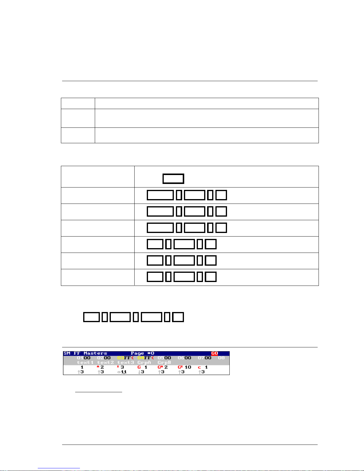
MASTERS AND PAGES 8-5
8.1.4 MODES
A cue or group loaded in a master can be several modes:
Normal
The master controls the output to scene of its cue or group.
Inhibit
The master inhibits the output to scene, from others playbacks, of its channels &
dimmers (htps). A inhibit cue or inhibit group never has output to scene.
Absolute
The master controls the output to scene of its cue or group, while the rest of the
masters output is forced to 0% progressively.
To load a cue or group in one of these modes, use the next commands:
Mode In these commands it’s possible to use any of the options of mode
selection ( LOAD, mouse, index number…)
GROUP
GROUP # LOAD 0 M#
GROUP Absolute
GROUP # LOAD 1 M#
GROUP Inhibit
GROUP # LOAD 2 M#
CUE
CUE # LOAD 3 M#
CUE Absolute
CUE # LOAD 4 M#
CUE Inhibit
CUE # LOAD 5 M#
The mode also can be selected when we load several masters at the same time;
Load cues from 1 to 5 in inhibit mode in the masters from 1 to 5 pressing:
CUE 1 THRU 5 LOAD 5 M1
8.1.5 MASTER IN MONITOR
Masters status line.
Master number & output level.
Group text or cues text.
Master content & mode.
Time information.
The masters status line shows us, from left to right:
• The level of the masters general fader, SM, from 0 to FF. If SM is under FF its level
appears in a red field. If its blackout key is active (LED at on), the SM flag appears in a red
field.
LEVITON 8700 SERIES
Page 94
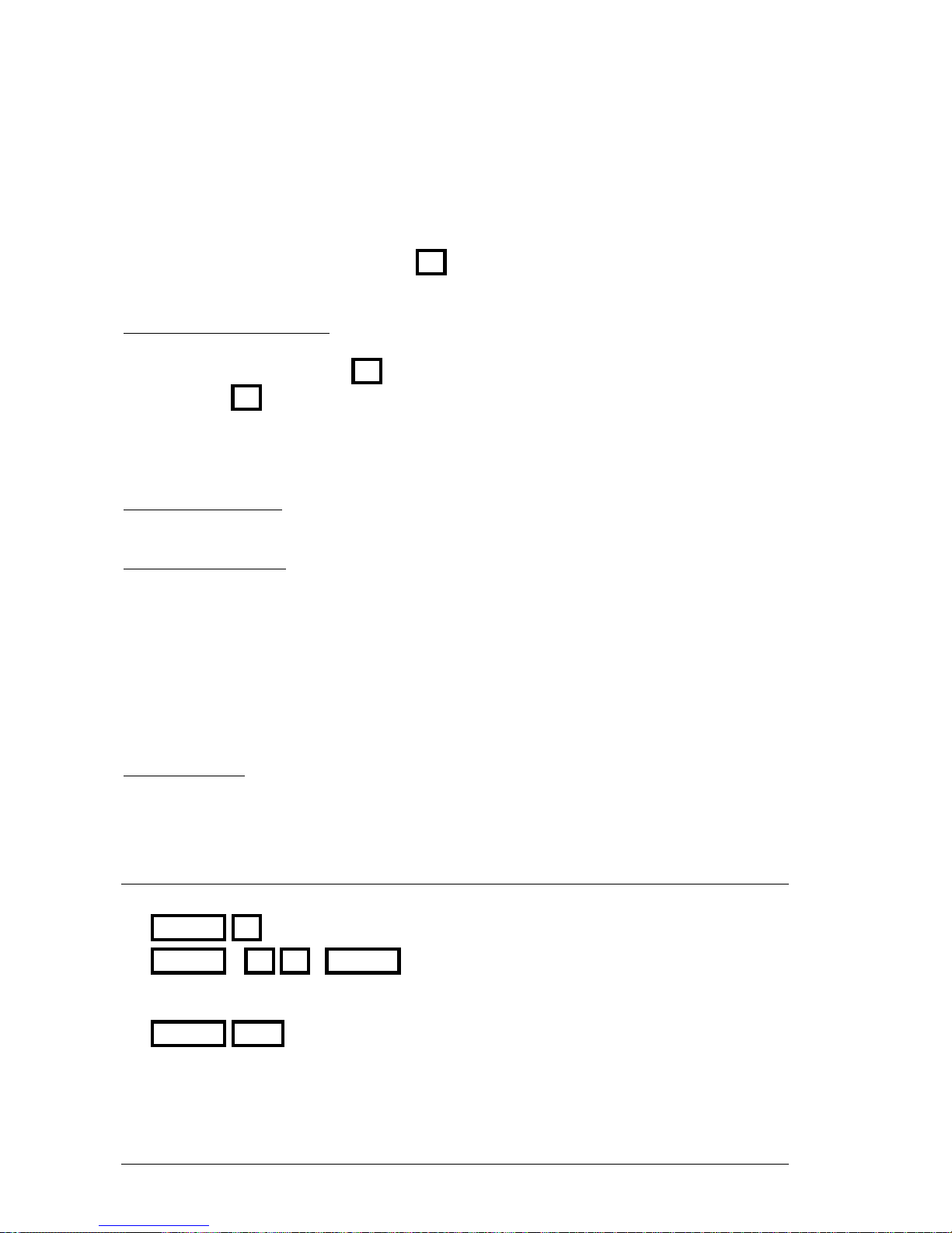
8-6 MASTERS AND PAGES
• After, you can see the SM configuration as Masters (when controls the masters output)
or Dmx In (when controls the Dmx input).
• After, the page number loaded appears. When some masters is modified (content) near the
page number a * appears. After the page number, if proceed, the page text appears.
• At the end, the current status of the M# keys appears, always in a red filed. This current
mode, for masters with groups, cues or channels, can be: GO, FLASH or SOLO.
Master number & output level:
Each master is identified by its number (00 to 24 or 48). This number appears in white when
the master isn’t active in scene ( M# LED at 50%), and appears in yellow when the master is
active in scene ( M# LED at 100% or blinking). Near the master number appears its output level
(00 to FF) in black.
When the master output level isn’t the same that the fader level (physically), the master is locked
and the flag < appears in red near the level.
Group text or cues text:
Under the master number, if proceed, the text of the loaded cue/group appears.
Master content & mode:
Under the text zone, the master content appears, and:
A normal cue is showed with its number: 1
An absolute cue is showed with its number preceded with an A in red:
A
2
An inhibit cue is showed with its number preceded with an
I
in red: I3
A normal group is showed with its number preceded with a G in red: G 1
An absolute group is showed with its number preceded with a G
A
in red: G A2
A inhibit group is showed with its number preceded with a G
I
in red: GI10
A channel, always normal, is showed with its number preceded with a c in red: c 1
Time information:
Under master content, its time information appears. This time is the time that is being
temporized (if master is active) or the first time to temporize (if master is inactive).
8.1.6 EMPTYING MASTERS
Empty a loaded master or several masters
DELETE M#
DELETET M# M#... DELETES
Empty all the masters:
DELETE FLMT
LEVITON 8700 SERIES
Page 95
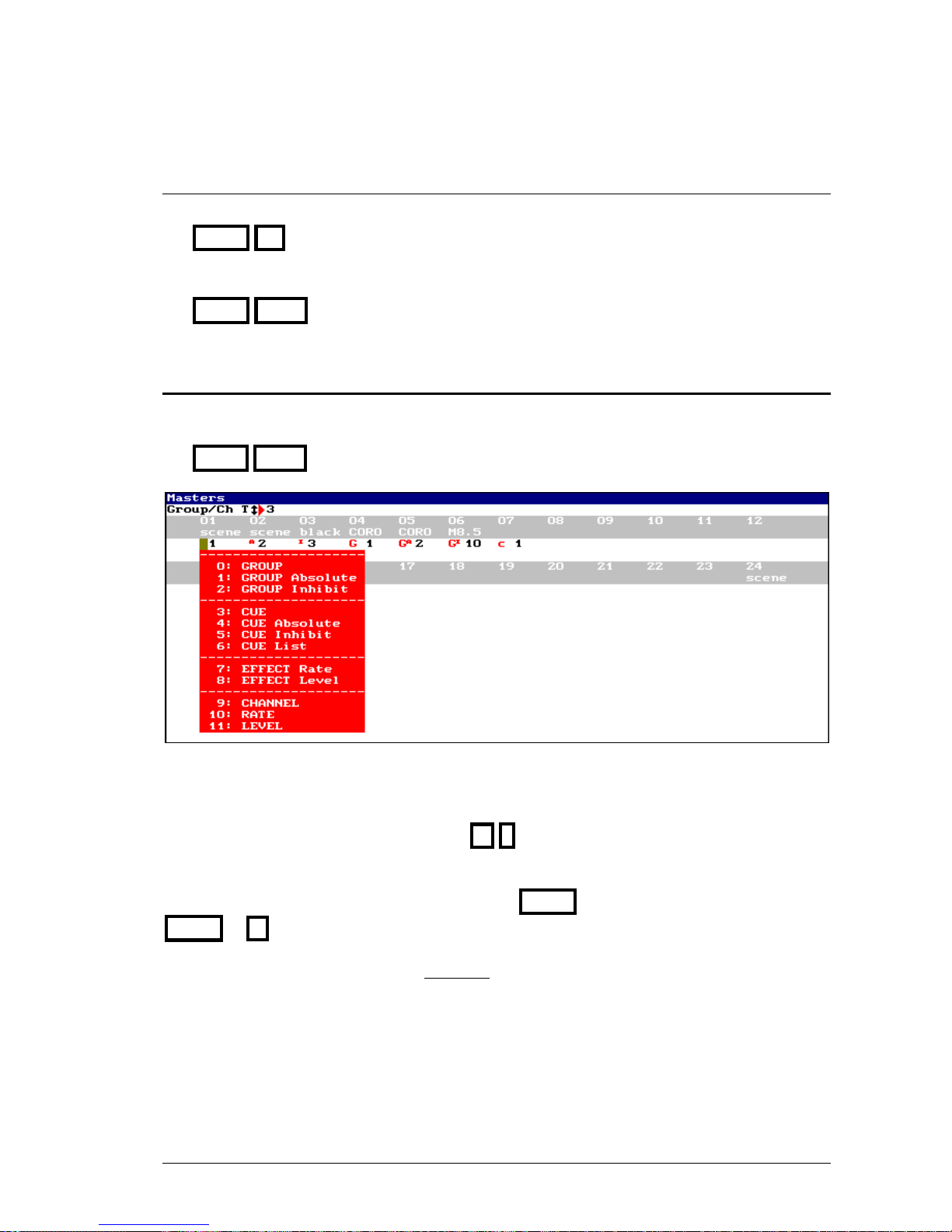
MASTERS AND PAGES 8-7
8.1.7 EXAMINING MASTERS
Exam a master content:
EXAM M#
Exam all the masters:
EXAM FLMT
8.2 MASTERS EDITION TABLE
All the functions of load in masters can be done from the masters edition table. Access to this
table pressing
MDFY FLMT
To load a master from this table, access to the desired master (using the arrows keys or the
external mouse) and select the load type amongst alls the options of the options window (entered
its index number or click it with the mouse), and then, move the cursor to the right and enter the
number of cue, group, channel, etc, pressing #
From the setup line it’s possible to change the default fade time assigned to groups and channels
(Group/Ch T). To access to the setup line press MENU. To return to the edition table press
MENU or
In this master edition table there are 2 options that only can be done from here. These options
are 10: RATE & 11: LEVEL. About them:
10: RATE Load a rate control to control the speed of the desired playbacks (Ra)
11: LEVEL Load a level control to control the output level of the desired playbacks (Le)
LEVITON 8700 SERIES
Page 96
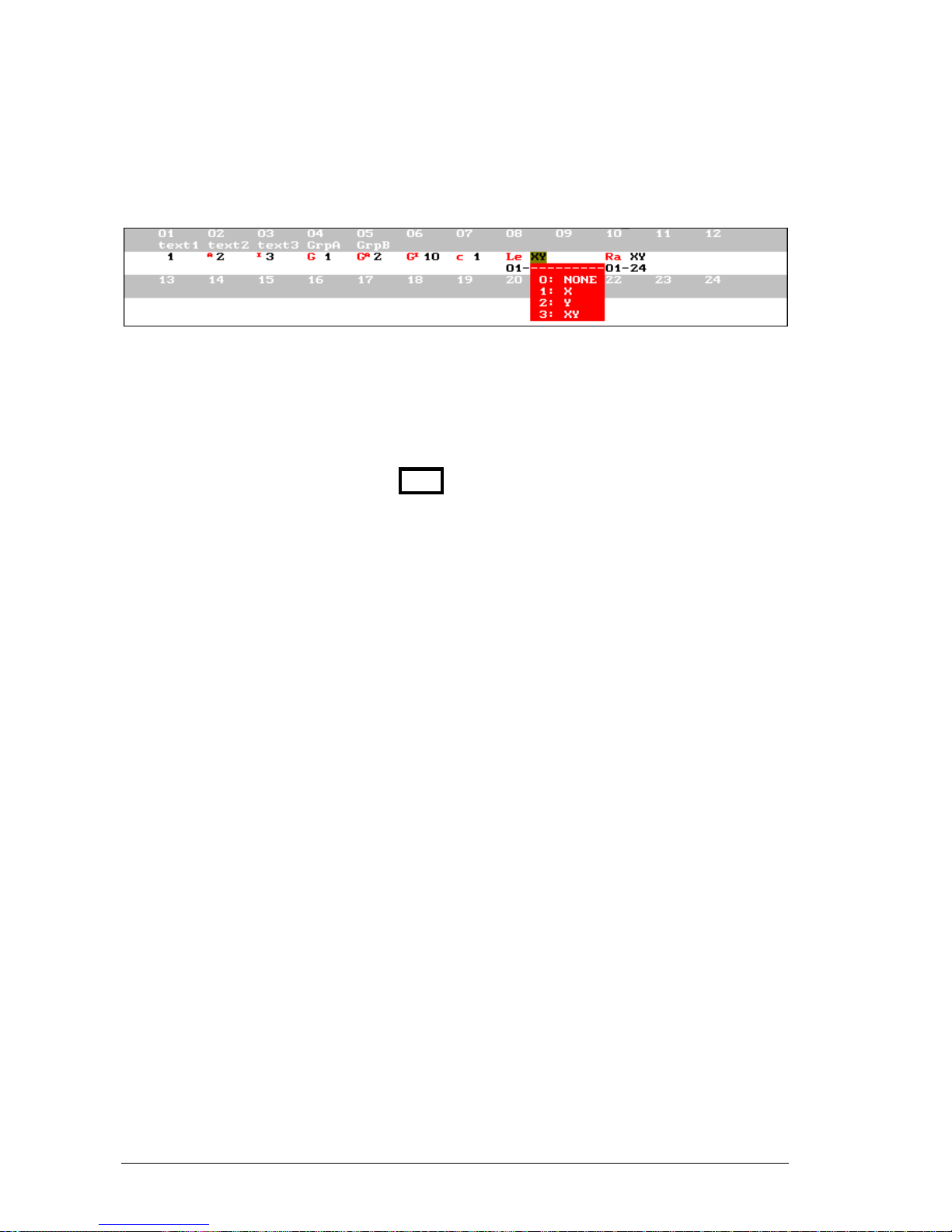
8-8 MASTERS AND PAGES
A master set as RATE or LEVEL permits us to configure the playbacks (masters and sequences)
over which this master has control. The next example is for a LEVEL master:
When the master is configured, the first option permits us to set if this master controls the
sequence X, or not (NONE).
The next options (in the lower line) permit us to set the masters range that will be controlled for
this master. In the previous example, 1-24, masters form M1 to M24.
To close this masters edition table press EXIT
LEVITON 8700 SERIES
Page 97
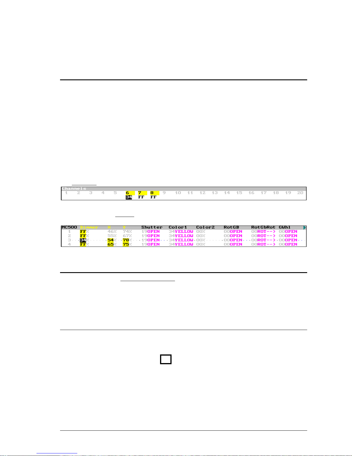
MASTERS AND PAGES 8-9
8.3 MASTERS IN SCENE
The master behavior depends of its content:
• Normal: When a channel, group or cue in normal mode is controlled with a master, its
contents appear in a yellow field in the auxiliary screens.
• Absolute: When a group or cue in absolute mode is controlled with a master, its content
(channels and/or fixture parameters) appears in a yellow field in the auxiliary screens. In this
case, at the same time that the output level of this master is increased, the output levels of the
rest of the masters are forced to 0% (progressively).
• Inhibit: When a group or cue in inhibit mode is controlled with a master, this master hasn’t
scene output. At the same time that the master level is increased, the output (coming from
other playbacks) of its htp contents (channels & dimmers) is forced, progressively, at 0%. In
this case, the output level of channels & dimmers appears in a black field.
Channels 6 to 8 are controlled in masters. Channel 6 is inhibited.
Dimmers of the fixtures 1 to 4 are controlled in masters, also the parameters x & y of the
fixtures 3 & 4 are controlled in masters. The dimmer of the fixture 3 is inhibited.
8.4 CONTROLLING A MASTER
A master loaded with a channel, group or cue can be controlled in the next modes:
• Manual
• Automatic
• Flash
8.4.1 MANUAL CONTROL
Manual control of a master is done moving its fader, M#. The fader position controls the
master output level (00-FF).
If M# is over its 0, active master, the M# LED is at 100%.
LEVITON 8700 SERIES
Page 98
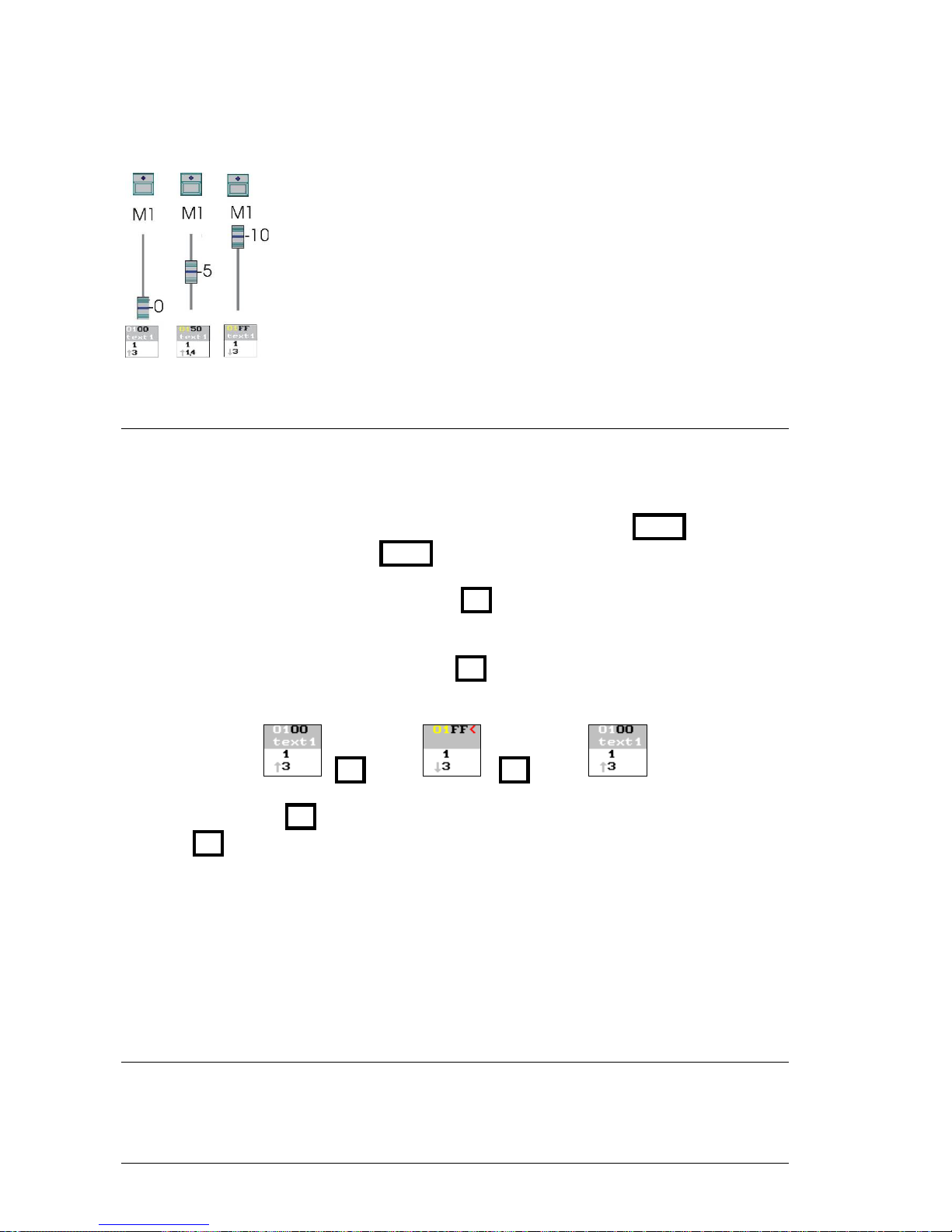
8-10 MASTERS AND PAGES
In this example, the master 1 has loaded the cue 1, and it is represented in
3 status:
a) Inactive, its output at 0%.
b) Active, its output at 50%.
c) Active, its output at 100%.
Under each master, the corresponding information just as appears in
monitor is showed.
8.4.2 AUTOMATIC CONTROL
The cues are controlled using their programmed times, and their timing or parts. Groups and
channels are controlled using its general fade time, Group/Ch T, groups, also, are controlled in
accordance with the default timing.
To control a master automatically, set the M# keys in GO mode, pressing FLMT as many times
as will be necessary to set GO mode ( FLMT LED at off).
Initially, the master is inactive at 0% (00). Press M# (GO) to fade in 100% (FF) in the fade-in
time (example: ↑3).
When the master is active at 100% (FF), press M# (GO) to fade out 0% (00) in the fade-out
time (example: ↓3).
M# (GO) M# (GO)
During these fades, the M# LED blinks (the master is temporizing), and it’s possible:
• Press M# to pause the fade in progress.
• Move M# to arrive the master output level (i.e. 50<) and take its control manually with the
fader.
If a cue has wait-in time (↑), this time is computed before that the fade-in time.
If a cue has auto time (), this time is computed after the fade-in time and before the fade-out
time, and all these times are computed automatically, one behind other. In other words, the
master is activated, remains a time in scene, and then is deactivated automatically.
If a cue has wait-out time (↓), this time is computed before that the fade-out time.
8.4.2.1 LTPs
Fixture parameters defined as FADE fades following the programmed times and timing.
Parameters defined as NO FADE jump to stored level and never fade.
LEVITON 8700 SERIES
Page 99
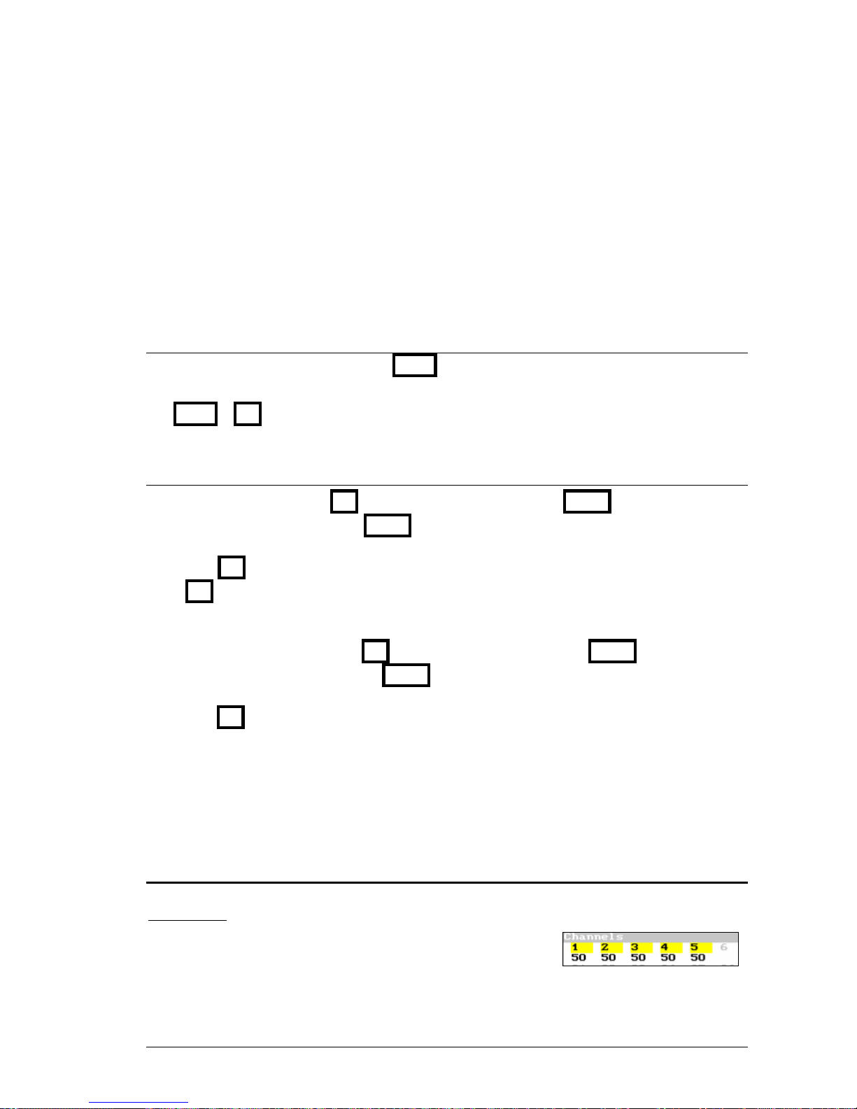
MASTERS AND PAGES 8-11
Always that the master doesn’t arrive to its 100%, LTP’s can return to their starting values. If
master has been activated in manual mode, and the Setup option, Manual Track is ENABLE,
LTP’s can return to their starting values including if the master arrives its 100%, in other cases,
the LTP values will remain in scene in tracking mode.
SM & GM don’t affect to the LTPs parameters.
In accordance with the LTP behavior, the last active master (manual or automatically) is the
master that take the control of these parameters.
8.4.2.2 MANUAL PRIORITY CONTROL
To change this priority order, use the PRIO function. Any active master takes priority again,
over its LTPs, pressing:
PRIOT M#
8.4.3 FLASH CONTROL
To do a master flash, set the M# keys in FLASH mode, pressing FLMT as many times as will
be necessary to set FLASH mode ( FLMT LED at on).
While that M#T is held down pressed, the master is at 100% in scene. It’s possible to press as
many M#T as will be needed.
To do a master flash-solo, set the M# keys in SOLO mode, pressing FLMT as many times as
will be necessary to set SOLO mode ( FLMT LED blinking).
While that M#T is held down pressed, the master is at 100% in scene, at the same time that the
rest of the masters are forced at 0%.
The SOLO function can influence to the crossfaders outputs. The level the Flash or Flash-Solo
(by default at 100%) can be changed. Both options are modified in menu 32: Masters. See
Chapter 14 - MENUS
8.5 MODIFICATION OF THE MASTERS CONTENTS
It’s possible to modify the scene (in the editor) and after to store this modification in the desired
group or cue that is loaded in a master.
Master at 100% that has the cue 1. The cue 1 has the
channels 1-5 at 50%.
LEVITON 8700 SERIES
Page 100
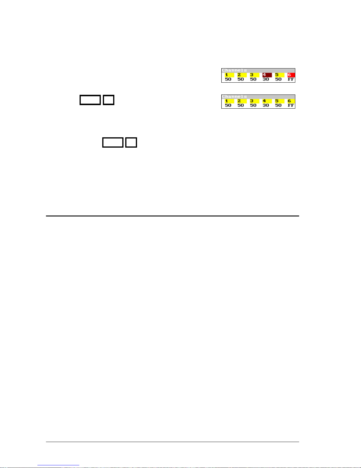
8-12 MASTERS AND PAGES
• Modify the desired items in the editor (Stage or Blind).
Example, edit the channel 4 at 30% and add the channel 6 at
100%.
• To store this modification in the cue 1 in the master #,
pressing MDFY M#
The editor content is added to the cue content. The editor is
emptied in 2 seconds.
Resume:
{modifications} MDFY M#
The master can be modified when is active at any level, or when is deactivated (at 00).
If the modifications are done in the Blind editor, they will be effectives in scene the next
time that the master is activated. In other words, the master content is maintained in scene
until the master arrives its 00.
8.6 THE MASTER OF MASTERS
The fader SM, by default, is the general master of the output of all the masters.
SM can be configured as master of masters or as general master of the DMX input. This
configuration is done inside menu 03: Dmx In or menu 31: Playbacks. See chapter 14.
LEVITON 8700 SERIES
 Loading...