

Page 1

Remote Control Panel
WEB VERSION
Installation &
Operation Guide
804CP / 808CP
Page 2

WEB VERSION
Page 2
Page 3

Table of Contents
WEB VERSION
INTRODUCTION ................................................................................................................. 4
IMPORTANT......................................................................................................................... 4
WIRING................................................................................................................................. 4
PROGRAMMING.................................................................................................................. 6
OPERATION ........................................................................................................................ 9
Page 4

Introduction
WEB VERSION
The Leviton 804CP and 808CP represents a key part of a state of the art, total lighting control
system. Combined with Leviton dimmers and optionally, a Leviton memory control console, a
totally integrated system is achieved.
The 804CP and 808CP can automatically take control and preset the lighting level of up to 100
dimmer channels. Control is automatically passed between control panels and the memory
control console as desired. The 804CP features 4 zone slide controls while the 808CP
features 8 zone slide control. Both units are exceptionally easy to operate. Remote lockout
capability is also included. Installation is a snap with the simple 4 wire digital connection
required.
Important
• Programming differs from other Luma-Net
• Luma-Net® control panels with software release 3.00 and higher are not directly compatible
and will not operate with older 400CP panels with software prior to release 3.00. Contact
dealer or factory for modifications if necessary.
• Leviton dimming systems used with these release 3.00 panels require the following
software releases:
2408CD, 2408CR, 2404CD release 2.30 and above.
DDS 8600/8800/9600/9800 release 1.30 and above. *
DDS 6000 release 1.30 and above. *
DDS 5300/5500/5600 release 1.30 and above. *
* Optional interface kit required for these units.
®
panels, please read instructions.
Wiring
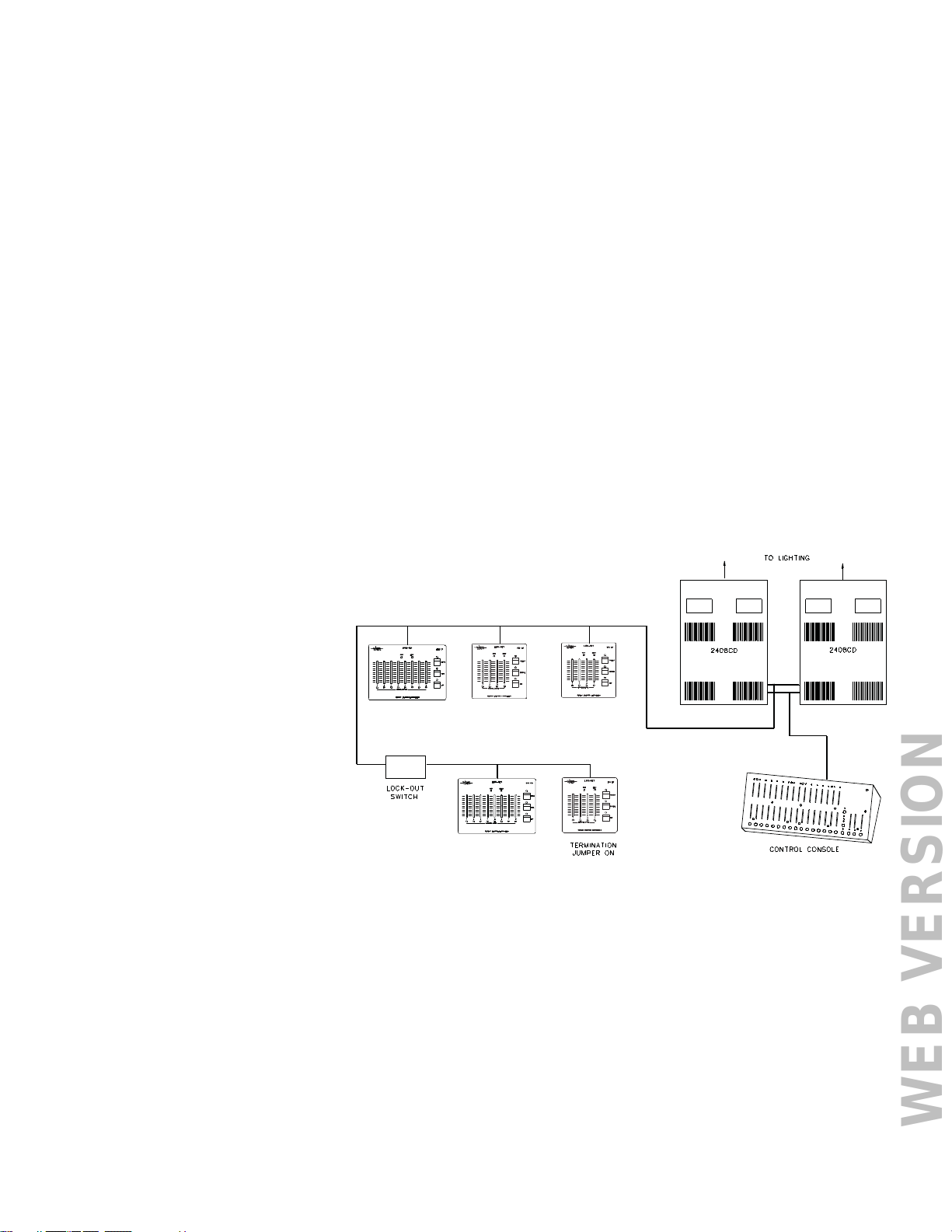
WIRING
The 804CP and 808CP will only operate with NSI dimming and control systems explicitly
designed for interfacing with it. Communication between the panels and the dimming system
is via a 4 wire interface. Three wires carry the RS 422/485 bi-directional data. A fourth wire
carries the DC voltage necessary for powering the unit.
Wiring cable between the panels and the dimming system is class 2 and should be at least
22 AWG, 4 conductor shielded, twisted pairs. (BELDEN 8302, 8723; 22 AWG.) Use 20 AWG
for runs over 500ft.
The 804CP and 808CP may be connected to the dimming system via parallel or daisy-chained
wiring. Due to power supply current demands, panels must be limited to 5 units per daisy
chain run with 22 awg wire, or 10 units with 20 AWG wire.
The Luma-Net
from the panel to facilitate ease of wiring and testing. Connect the terminals marked remote+,
remote-, common, and +15 VDC to the same respective terminals on the dimming system and
other Luma-Net® panels. Use one twisted pair for remote+ and remote- and the other pair for
common and +15 VDC.
The wiring to the remote lockout switch, if used, can be simple 2 conductor 22 AWG. Connect
the wires from the switch to the lockout+ and lockout- terminals. Any panel or group of panels
may be locked-out remotely by interrupting the +15V supply to the panels. This should not
affect any other panels still powered, or affect lighting levels currently set.
IMPORTANT: Verify wiring is correct before powering system! Make sure nothing
conductive may touch pc board or components!
®
panels feature plug on wiring terminals. The terminals may be unplugged
Page 4
Page 5
MOUNTING
WEB VERSION
The 804CP and will mount in any standard double-gang electrical box, while the 808CP will mount in a
large three-gang box with the 4 screws provided. See below paragraph on system turn-on before final
mounting of panels.
SYSTEM TURN-ON
It is very important that the system operation be verified one panel at a time or else an improper
connection at one panel would cause the entire system to not operate properly and may be difficult to
diagnose.
After all terminal plugs have been wired and the dimmer system has been installed and tested, the
installer is ready to connect each panel to the system. Panels may be plugged-in while system is live,
but the installer must take care not to touch PC board or connections with fingers or metal objects.
On daisy-chain runs, the panels closest to the dimming system should be connected first.
804CP and 808CP panels have dip switches to set network ID number and must have their ID
programmed before the system power is connected. It is recommended that the installer review the
programming procedures for network ID before proceding. A duplicate network ID number will cause the
entire network to malfunction.
Connect the first panel and immediately notice whether the POWER LED comes on, indicating power to
the panel. The BUSY LED should come on momentarily and then go out and stay out. This indicates a
successful reconfiguration of the network. If the BUSY LED flashes slowly, this indicates a duplicate ID
number or wiring problem. Program the ID number, if not already, and observe the BUSY LED
(Note - the busy LED also flashes quickly when the program jumper is removed).
Now test the dimmer function by operating the panel. If the dimmer responds, then mount the panel and
procede to the next panel in the system and follow the same procedure.
LEDS
The PWR LED indicates the
presence of +15VDC to the panel.
The CONTROL ACTIVE green
LED’s indicate that the panel has
control over any dimmers assigned
to the repective zone and the
dimmer levels have not been
altered by any other panel. The LED
will go out as soon as another panel
changes the levels of any dimmer
assigned to that particular zone.
The BUSY LED indicates the
following:
Off Normal: State when there is no
activity.
Short Blinks: A message is being
sent on the network.
Steady on or Slow flashing: Network
trying to reconfigure (bad ID?)
While programming, the following actions are normal:
Quickly flashing Programming mode, no mode selected.
Off Programming mode, mode selected.
LOCKOUT
Any 804CP and 808CP may be disabled from operation with a remote key switch or other contact
closure. Several Luma-Net® panels of the same version may be connected to the same contacts in
parallel as long as polarity is maintained.
Closing the contact will prevent connected panels from operating, regardless of button presses.
Luma-Net
the panels.
®
panels may also be locked out by causing a switch to disconnect the +15V supply to
Page 5
Page 6
Programming
WEB VERSION
The 804CP and the 808CP come from the factory programmed for the following, unless
special factory programming
was requested:
Dimmer channels for each zone: Zone 1-4 (1-8) = Ch 1-4 (1-8) respectively
Fade time for each zone and presets: 1 second
PRESET button levels: Zone 1-4 (1-8) full
ALL OFF button levels: Zone 1-4 (1-8) off
The installer may reprogram the PRESET and ALL OFF buttons easily without additional
equipment. Other features such as dimmer channel assignment and fade time require a
computer and software.
Details on programming other features are supplied with the Luma-Net
Optionally, the unit may be ordered preprogrammed from the factory.
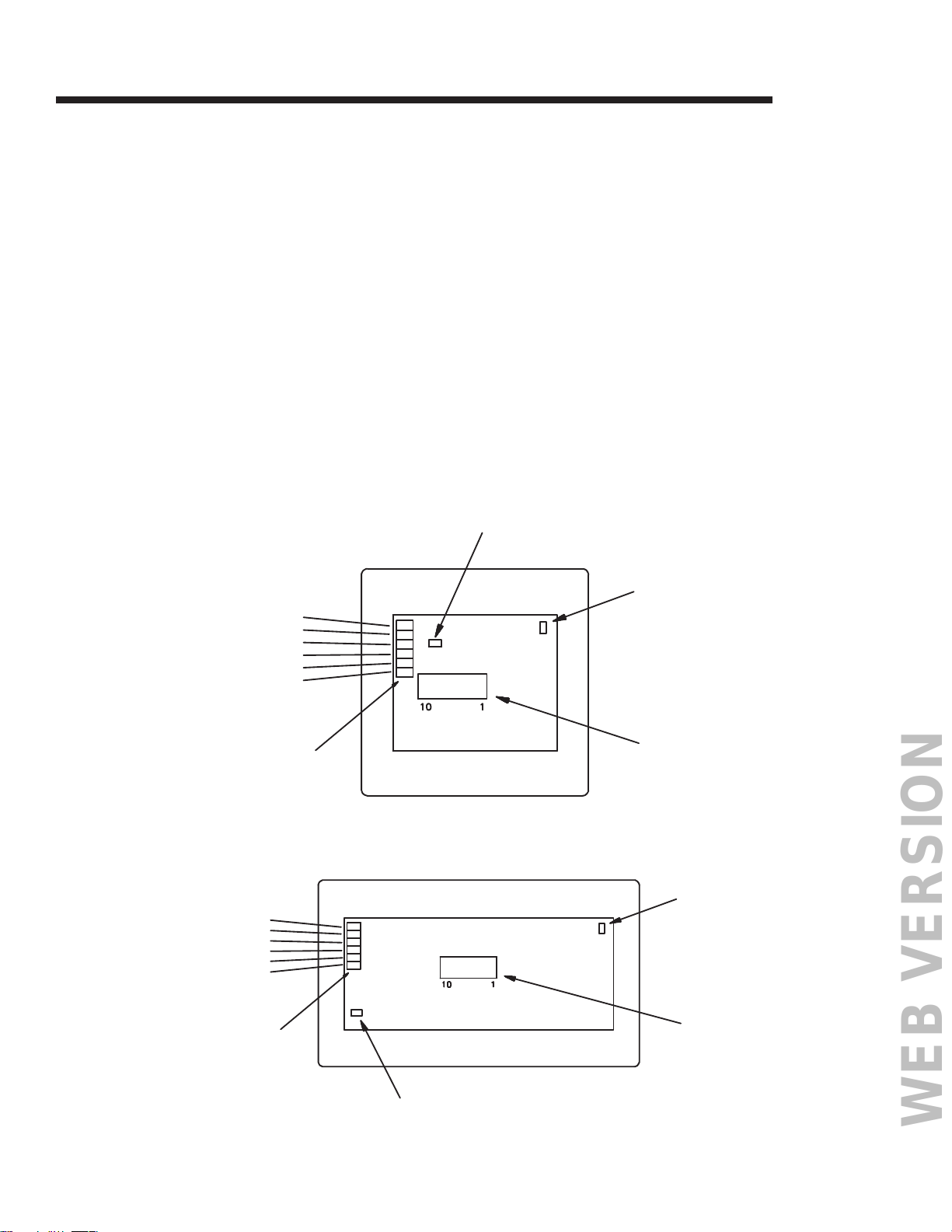
REAR VIEW OF 804CP
TERMINATION
JUMPER
®
Software Package.
LO+
LO-
+VDC
COM
REM-
REM+
TERMINAL
BLOCK
LO+
LO+VDC
COM
REMREM+
TERMINAL
BLOCK
REAR VIEW OF 808CP
PROGRAM
JUMPER
ID NUMBER
DIP-SWITCH
PROGRAM
JUMPER
ID NUMBER
DIP-SWITCH
TERMINATION
JUMPER
Page 6
Page 7

Programming the PRESET and ALL OFF buttons:
WEB VERSION
In order to program panels, a jumper block must be removed from the program jumper pins.
This will allow data to be stored in the eeprom memory. At this point the BUSY LED will start
flashing, indicating that you are in the program select mode.
IMPORTANT: After programming it is important to replace the programming jumper block
so memory will be protected. DO NOT press all three buttons down simultanously while the
jumber is removed, this will erase programming.
To program:
1. Make sure that the 804CP or 808CP is in the program select mode as discussed. The
BUSY LED should be flashing.
2. Set the zone levels as desired using the slide controls.
3. Press the PRESET or ALL OFF button to store the new zone levels.
4. Replace the programming jumper. Test the button operation.
Network ID number
Network ID number must be set to a uniqe number (IMPORTANT).
Since the Luma-Net
dimmers) must have a unique network ID number.
If two panels have the same network ID number, the entire network will stop
functioning.
®
System is a digital network, all panels and devices attached (except
Panels need not be in program mode to change network ID number, since a dipwitch is used.
To set Network ID number:
1. Locate dipswitch on rear of unit as illustrated below.
2. Set the switches as per the chart on the following page.
Factory Default Setting:
The 804CP and 808CP are programmed at the factory for zone 1-4 (1-8) to be set for dimmer
channel 1-4 (1-8) respectively. PRESET is programmed for dimmers 1-4 (1-8) full on. ALL OFF
is programmed for dimmers 1-4 (1-8) off. The fade rate and other parameters are also set to
factory defaults. This may be acceptable for initial testing. If it is necessary to return the panel
to it’s factory default settings (except network ID), follow this procedure:
Caution: Special factory programming will be lost.
1. Remove program jumper block and disconnect plug-in terminal block.
2. Hold down all pushbuttons while connecting terminal block.
3. Setting is complete when busy light begins to flash after several seconds.
Page 7
Page 8

ID number codes / dipswitch settings
WEB VERSION
ID number 12345678 ID number 12345678 ID number 12345678
0 00000000 1 10000000 2 01000000
3 11000000 4 00100000 5 10100000
6 01100000 7 11100000 8 00010000
9 10010000 10 01010000 11 11010000
12 00110000 13 10110000 14 01110000
15 11110000 16 00001000 17 10001000
18 01001000 19 11001000 20 00101000
21 10101000 22 01101000 23 11101000
24 00011000 25 10011000 26 01011000
27 11011000 28 00111000 29 10111000
30 01111000 31 11111000 32 00000100
33 10000100 34 01000100 35 11000100
36 00100100 37 10100100 38 01100100
39 11100100 40 00010100 41 10010100
42 01010100 43 11010100 44 00110100
45 10110100 46 01110100 47 11110100
48 00001100 49 10001100 50 01001100
51 11001100 52 00101100 53 10101100
54 01101100 55 11101100 56 00011100
57 10011100 58 01011100 59 11011100
60 00111100 61 10111100 62 01111100
63 11111100 64 00000010 65 10000010
66 01000010 67 11000010 68 00100010
69 10100010 70 01100010 71 11100010
72 00010010 73 10010010 74 01010010
75 11010010 76 00110010 77 10110010
78 01110010 79 11110010 80 00001010
81 10001010 82 01001010 83 11001010
84 00101010 85 10101010 86 01101010
87 11101010 88 00011010 89 10011010
90 01011010 91 11011010 92 00111010
93 10111010 94 01111010 95 11111010
96 00000110 97 10000110 98 01000110
99 11000110 100 00100110 101 10100110
102 01100110 103 11100110 104 00010110
105 10010110 106 01010110 107 11010110
108 00110110 109 10110110 110 01110110
111 11110110 112 00001110 113 10001110
114 01001110 115 11001110 116 00101110
117 10101110 118 01101110 119 11101110
120 00011110 121 10011110 122 01011110
123 11011110 124 00111110 125 10111110
126 01111110 127 11111110
For channels 129 - 256 Set dipswitch 1-7 as above and set dipswitch #8 on.
Page 8
Page 9
Operation
WEB VERSION
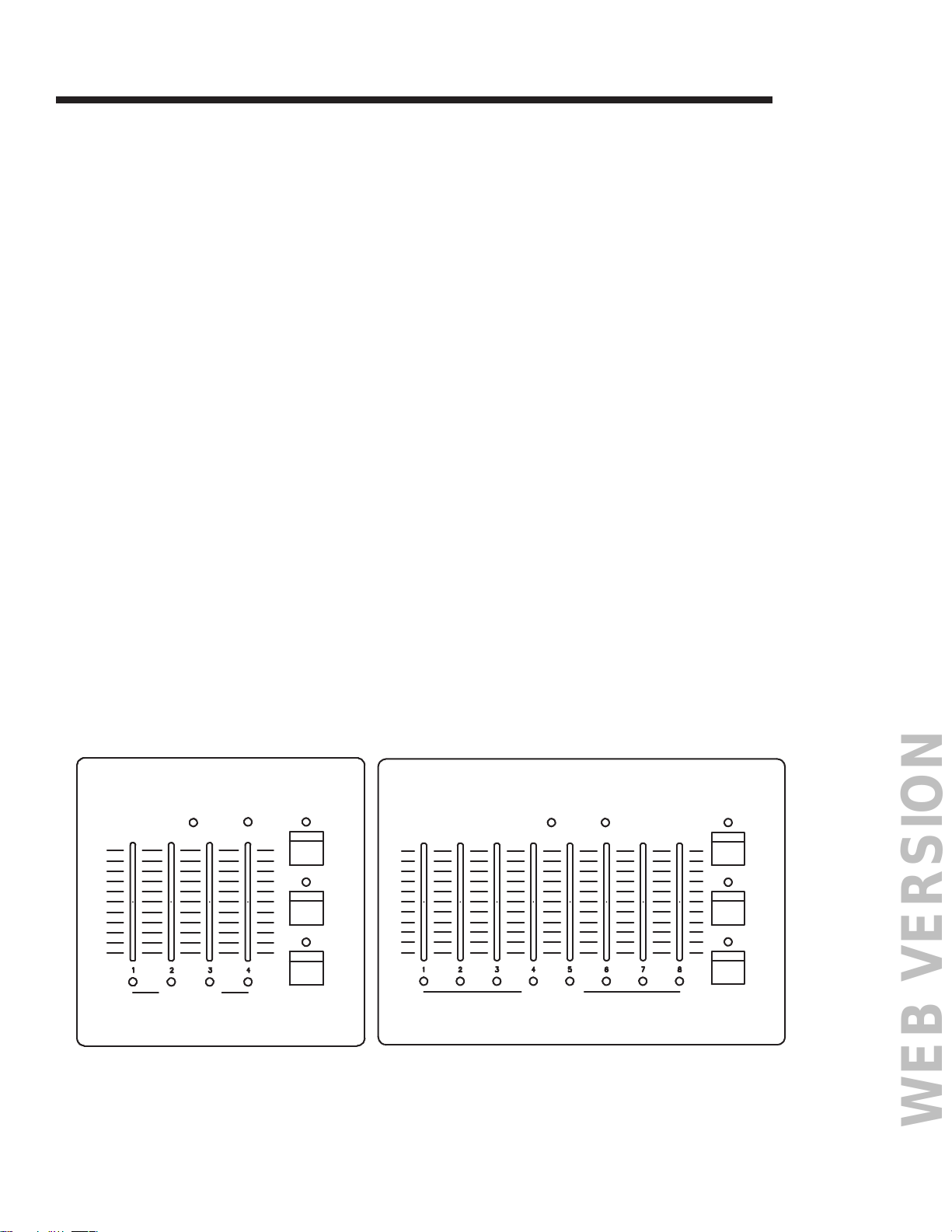
Slide controls:
Moving a slide control will cause an immediate takecontrol of all dimmers assigned to that
zone. The lighting levels will fade up or down quickly to match the slide control level, and the
LED of the zone will illuminate indicating that the slider has full control (This feature may be
modified through computer software wheras the MANUAL button must first be pressed to gain
control).
The LED of the zone will go out when either the PRESET or ALL OFF button is pressed, or if
another panel gains control of the dimmer channel assigned (A control console will not affect
the LEDs).
Default dimmer assignment are : Zone 1-4 (1-8) = Dimmer Channel 1-4 (1-8).
MANUAL button:
When pressed, this button will cause all dimmer channels assigned to all zones of this panel
to fade to the current settings of the slide controls. All zone LEDs will come on and the slide
controls will have full control.
PRESET button:
This button will cause all dimmer channels assigned to all zones of this panel to fade to the
zone setting previously programmed (Default is all full on). All zone LEDs will go out.
ALL OFF button:
This button will cause all dimmer channels assigned to all zones of this panel to fade to the
zone setting previously programmed (Default is all full off). All zone LEDs will go out.
To restore control from a console:
Simply perform a change in the channel level from the console. The lighting channel will
then fade back to the new console level at the factory default fade rate. Once the console
level matches or is moved past the lighting level, full console control will be resumed for that
channel.
LUMA-NET
PWR BUSY PWR BUSY
804 CP
PRESET
MANUAL
OFF
LUMA-NET
808 CP
PRESET
MANUAL
OFF
MEMORY LIGHTING CONTROLLER
CONTROL ACTIVECONTROL ACTIVE
MEMORY LIGHTING CONTROLLER
Page 9
Page 10

NOTES
WEB VERSION
Page 10
Page 11

NOTES
WEB VERSION
Page 11
Page 12
FOR CANADA ONLY
WEB VERSION
For warranty information and/or product returns, residents of Canada should contact Leviton in writing at
Leviton Manufacturing of Canada Ltd to the attention of the Quality Assurance Department, 165
Hymus Blvd, Pointe-Claire (Quebec), Canada H9R 1E9 or by telephone at 1 800 405-5320.
LIMITED 2 YEAR WARRANTY AND EXCLUSIONS
Leviton warrants to the original consumer purchaser and not for the benefit of anyone else that this
product at the time of its sale by Leviton is free of defects in materials and workmanship under normal
and proper use for two years from the purchase date. Leviton’s only obligation is to correct such defects
by repair or replacement, at its option. For details visit www.leviton.com or call 1-800-824-3005. This
warranty excludes and there is disclaimed liability for labor for removal of this product or reinstallation.
This warranty is void if this product is installed improperly or in an improper environment, overloaded,
misused, opened, abused, or altered in any manner, or is not used under normal operating conditions or
not in accordance with any labels or instructions. There are no other or implied warranties of any kind,
including merchantability and fitness for a particular purpose, but if any implied warranty is required by
the applicable jurisdiction, the duration of any such implied warranty, including merchantability and fitness
for a particular purpose, is limited to two years. Leviton is not liable for incidental, indirect, special, or
consequential damages, including without limitation, damage to, or loss of use of, any equipment,
lost sales or profits or delay or failure to perform this warranty obligation. The remedies provided
herein are the exclusive remedies under this warranty, whether based on contract, tort or otherwise.
For Technical Assistance Call: 1-800-824-3005 (U.S.A. Only) www.leviton.com
Page 12 DI-000-N080X-00F© 2016 Leviton Mfg. Co., Inc.
 Loading...