

Page 1

User’s
Manual
TL-F20 CNC Lathe
CNC Turning Certification Cart
Levil Technology Corp. reserves the right to alter any specifications and
documentation without prior notice. No part of this manual or its accompanying
documents may be reproduced or transmitted in any form or by any means, electronic
or mechanical, for any purpose, without the express written permission of Levil
Technology Corp.
Page 2

1
Contact Information
Address: 1704 Kennedy Point
Ste 1124
Oviedo, FL 32765
Telephone: 407-542-3971
Fax: 407-542-3971
Technical Support: Monday to Friday 10:00am – 5:00pm Eastern (EST)
Notes:
____________________________________________
____________________________________________
____________________________________________
____________________________________________
____________________________________________
____________________________________________
____________________________________________
____________________________________________
____________________________________________
TL-F20 CNC Lathe User’s Manual
Page 3

2
Table of Contents:
1. General ......................................................................... 4
I. Introduction..................................................................................................................................... 4
II. Safety Precautions ......................................................................................................................... 4
III. Warm Up .......................................................................................................................................... 5
IV. Coolant ............................................................................................................................................. 5
V. Treatment of Waste ....................................................................................................................... 6
2. Machine Specifications ...................................................... 7
I. General Specifications .................................................................................................................. 7
II. Dimensional Drawings .................................................................................................................... 7
III. Working Space Required ............................................................................................................... 9
IV. Caution Labels on the Machine .................................................................................................. 10
V. Machine Specifications ................................................................................................................ 12
VI. Standard Accessories ................................................................................................................... 13
VII. Optional Accessories .................................................................................................................... 13
VIII. Power Specifications............................................................................................................ 14
IX. Axis movement ............................................................................................................................. 15
3. Machine Installation ......................................................... 16
I. General Preparation & Selecting Location .............................................................................. 16
II. Foundation and Layout ................................................................................................................ 17
III. Installation Procedure ................................................................................................................. 18
IV. Checkups during the Test Run ................................................................................................... 19
V. Relocation of the Machine .......................................................................................................... 20
4. Operation ...................................................................... 21
I. Overview of the Operator Interface ......................................................................................... 21
II. Overview of Machine Operator Panel Functions ..................................................................... 22
III. Machine Start Up and Shut Down Procedure ........................................................................... 27
IV. Spindle Operation ........................................................................................................................ 28
V. Setting the Work-piece Coordinate System ............................................................................. 30
VI. Setting Tool Length Offset ......................................................................................................... 31
TL-F20 CNC Lathe User’s Manual
Page 4

3
VII. Automatic Tool Change Operations .......................................................................................... 32
VIII. Coolant System Operation .................................................................................................. 34
5. Maintenance .................................................................. 35
I. APC warning and “DS0300 APC alarm: Need Ref Return” ..................................................... 35
II. Aligning the spindle head and the tool turret......................................................................... 37
III. Ball Screw Lubrication Procedure ............................................................................................. 38
IV. Linear Guide Way Lubrication Procedure ................................................................................ 41
V. Servo Adjustment ......................................................................................................................... 42
VI. Cleaning the Machine .................................................................................................................. 43
VII. Coolant system ............................................................................................................................. 44
VIII. Wiring Diagrams .................................................................................................................... 45
TL-F20 CNC Lathe User’s Manual
Page 5

4
1. General
I. Introduction
This manual specifies the proper maintenance and operation of the TL-F20 CNC
lathe. It benefits both experienced and beginner CNC machine operators and
should be read thoroughly by all users.
All guidelines included in this manual should be studied and understood to
ensure the safety of the operator and to prevent any substantial damage to the
machine.
II. Safety Precautions
1) Operators should not touch any high-voltage terminals such as those found
in control panels, transformers, motors, or junction boxes. Severe electric
shock will be sustained otherwise. Electric shock may also result from
touching a switch with wet hands.
2) The emergency stop button’s location should be well known so that it can
be pressed as soon as possible in case a critic situation.
3) Power off the machine before switching a fuse.
4) Do not operate this machine during violent thunderstorms. Lightning can
cause equipment failure
5) Do not work with long hair that can be caught in the machine, keep it out of
the way with a net or by tying it at the back.
6) Provide enough working space around the machine to avoid falls.
7) Since water and oil can make the floor slippery, all floors should be kept
clean and dry.
8) Never touch a switch accidentally. If operating a switch, make sure it is the
right one.
9) Do not handle coolant with bare hands since it may cause some irritation.
10) Do not remove or tamper with safety devices such as stop dogs, limit
switched, or interlocks in order to increase the range of axis travel.
11) Keep a fire extinguisher at hand in case of fire or explosion due to cutting
flammable materials. Please ask your material provider for safety guidelines
when cutting volatile materials.
12) Hold work-pieces securely inside the chuck.
13) Stop machine operation before adjusting the coolant nozzle tip.
TL-F20 CNC Lathe User’s Manual
Page 6

5
14) To remove a work-piece from the machine, stop the spindle and provide
plenty of space from the work-piece to the tool turret.
15) Do not operate the machine with the safety front door open.
16) Stop machine operation before installing or removing a tool.
17) Never wear loose or baggy clothing when operating the machine.
18) Never operate the machine under the influence of alcohol or any other
drug.
19) The operator should wear safety glasses to avoid flying debris or coolant
from making contact with his/her eyes.
20) Keep the machine clean. Do not let too many metal chips accumulate in the
work area.
21) Check the chip filter in the coolant tank, if too many chips accumulate, the
coolant will overflow and leak on the ground, resulting in a slip hazard.
22) Before leaving the machine at the end of the day, press the emergency
button, turn off the power button, and the main switch on the back of the
machine.
23) Keep hands clear of the pinch area around the X axis servo motor. Serious
injury can result from pinched hand and/or fingers.
III. Warm Up
1) Every day before use, warm up the machine by turning on the spindle for 10
minutes at about 1000-1500 rpm. Failure to do so may result in a shorter
lifespan of the spindle bearings.
2) If the machine is used right after being started, following a long idle period,
sliding parts may wear down due to lack of even lubrication. Furthermore,
thermal expansion of the machine components may jeopardize machining
accuracy. To prevent these outcomes, always warm up the machine before
daily operation by moving each axis through their entire travel at 50% of the
machine’s rapid speed for 10 minutes.
IV. Coolant
1) Use water-soluble coolant. If oil-based coolant is used, the coolant
temperature will rise, causing thermal distortion of the machine. Oil-based
coolants are also flammable so more care must be taken to avoid fires.
TL-F20 CNC Lathe User’s Manual
Page 7

6
2) Make sure that the coolant used has no adverse effects on the human body.
Since water-based coolants often cause poisoning, pay sufficient attention
to the hygiene of the operator.
3) Make sure that the coolant does not cause curing or expansion of rubber or
plastic products, or chemical products.
4) Make sure to maintain the water-soluble coolant at the right concentration
for best results, otherwise the solution can become stale.
V. Treatment of Waste
1) Deposit metal chips and left over work-piece metal in a bucket. Appoint a
local qualified scrap metal company to dispose of it.
2) Store waste coolant and lubricant in separate containers to be disposed of
by some qualified recycling or sewage treatment company.
TL-F20 CNC Lathe User’s Manual
Page 8

7
1) Control Enclosure
11) Coolant Power
2) Manual Pulse
Generator (MPG)
12) Machine Power
Cable
3) Machine Enclosure
Casing
13) Main Electronics
Enclosure
4) Work Area Access
Door
14) Main Switch
5) Coolant Return
Hose Connection
15) Access panel to
electronic enclosure
6) Machine Legs
16) Compressed Air
Connection
7) Machine Control
17) Z axis Servo
8) Operator Panel
18) X axis Servo
9) Access Panel to
Spindle and drivers
19) Access to control
casing
10) Machine Serial
Number
2. Machine Specifications
I. General Specifications
TL-F20 CNC Lathe User’s Manual
Page 9

8
II. Dimensional Drawings
The following figure represents a side view and a front view of the machine with their
respective measurements.
Fig. 3 TL-F20 CNC lathe dimensions from side view (right) & front view (left)
TL-F20 CNC Lathe User’s Manual
Page 10

9
III. Working Space Required
The following top view drawing of the machine depicts the necessary working
space required for easy operation and maintenance of the machine.
Fig. 4 Top view of working space, all dimensions in mm
TL-F20 CNC Lathe User’s Manual
Page 11

10
(1)
WARNING:
Moving parts can crush and cut.
Do not operate with guard
removed.
Follow lockout procedure before
servicing.
(2)
WARNING:
Flying objects.
Wear approved eye protection
when operating this equipment.
(3)
WARNING:
Pinch Point.
Keep hands clear during operation.
IV. Caution Labels on the Machine
Caution labels provide the operator with safety related information that must
be strictly observed. These labels can be found in the outlined locations given
in Fig. 1-2.
Table I: Safety label picture and instruction.
TL-F20 CNC Lathe User’s Manual
Page 12

11
(4)
WARNING:
Electrical Hazard.
110 VAC and 220 VAC running
through the system.
(5)
Danger:
Do not operate without guards in
place
(4)
Only 110 VAC are to be supplied
through this cable.
TL-F20 CNC Lathe User’s Manual
Page 13

12
Description
CNC Turning Certification Cart
Capacity
Swing over bed
220 mm (8.6")
Max cutting diameter
38 mm (1.5”)
Max bar diameter
19 mm (3/4”)
Travel
X Axis
180 mm (7")
Z Axis
160 mm (8.5")
Resolution
0.001mm (0.00004")
Repeatability
0.005mm (0.0002")
Accuracy
0.01mm (0.0004")
Spindle (LS-32)
Spindle Chuck
4” dia, self-centering 3 jaws
Spindle Speed
100 – 3,000 rpm
Drive Method
Direct Drive
Spindle Motor Power
2HP
Spindle Torque
1.5 Nm
Alternative Spindle Options
LS-32HS
100 – 4,000 rpm, 2HP, 220 VAC
Feed
Rapid Feed (X, Y & Z)
10,200 mm/min (400 ipm)
Cutting Feed (X, Y & Z)
6,120 mm/min (240 ipm)
BTP-50 Turret
Number of Tools
8
Tool Change Method
Turret rotation
External Tool Shank
12.7 mm (1/2”)
Internal Tool Shank diameter
19.01 mm (3/4")
Machine Weight
Basic Setup
204 kg (450 lbs)
Utilities
Air Consumption
87 L/min (3 cfm)
Power
110V, 20A
V. Machine Specifications
Table II: Machine specifications and capacity.
TL-F20 CNC Lathe User’s Manual
Page 14

13
VI. Standard Accessories
1) Coolant system
2) Metal chip filter
3) Through turret coolant
4) Splash guard
5) 8 Position tool turret with 4 ID tool holders for ¾” shank dia.
6) Operating manual
7) FANUC 0i-Mate D Operating Manuals
VII. Optional Accessories
1) LS-32HS spindle: Direct drive 4,000 rpm ATC spindle (220 VAC required)
2) Automatic tool length measurement.
3) Tail Stock
4) Steel Machine Stand with leveling casters.
TL-F20 CNC Lathe User’s Manual
Page 15

14
Item
TL-F20 CNC Lathe
Voltages
1-phase, 110V
Frequency
50/60 Hz ± 1 Hz
Voltage Tolerance
± 10% or below
Power gross load capacity
2 HP (1.40 KVA)
Primary power cable
4 mm2 or more
Grounding cable
4 mm2 or more
VIII. Power Specifications
Table 3: Power specifications
TL-F20 CNC Lathe User’s Manual
Page 16
15
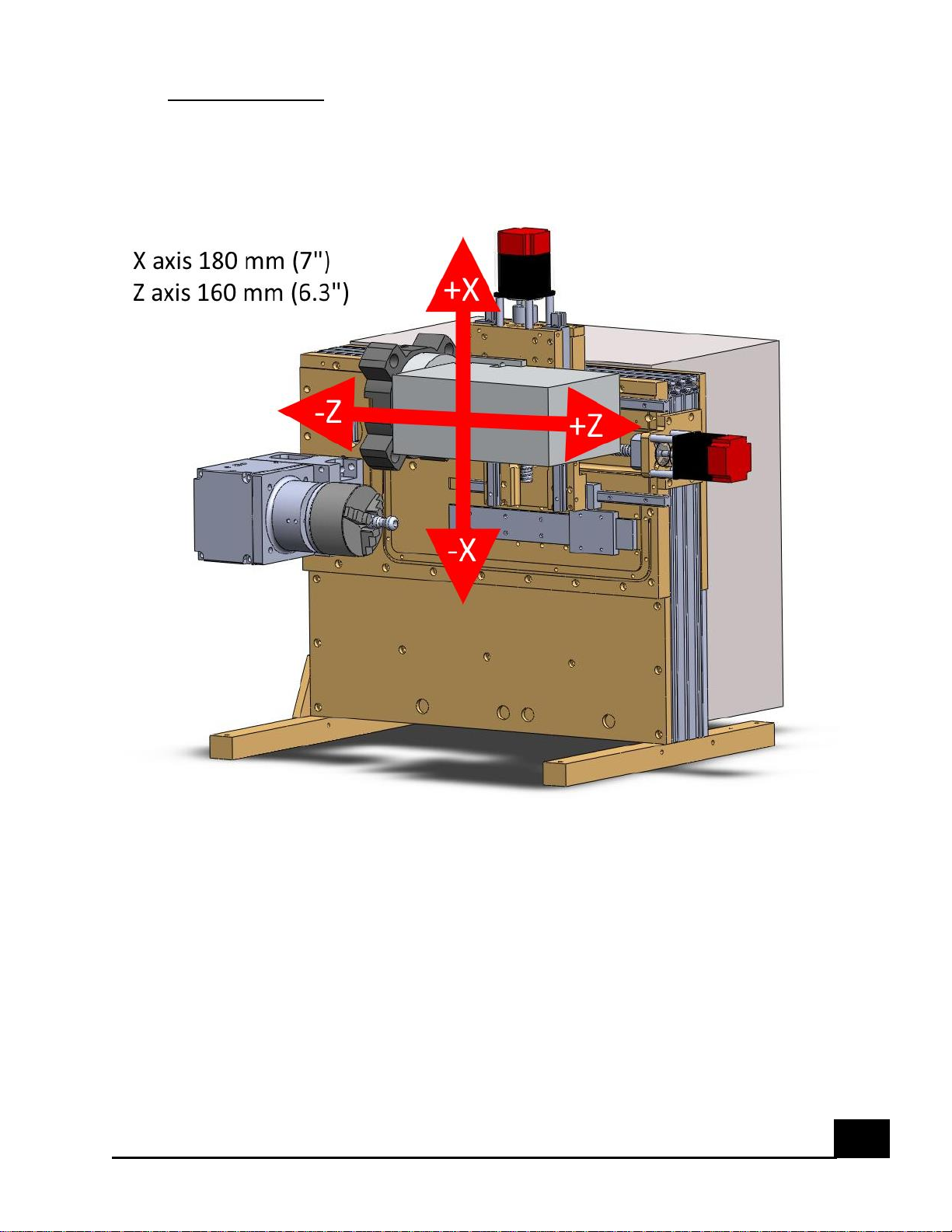
IX. Axis movement
Fig. 7 Positive and negative axis movements for the machine
TL-F20 CNC Lathe User’s Manual
Page 17

16
3. Machine Installation
I. General Preparation & Selecting Location
Do not power on the machine until the installation preparations are completed.
Never open the electronics bay cabinet door with the power on, high voltage
will be present in the electronics bay and there will be a risk of shock or injury.
It is recommended to place the machine in an air conditioned environment
where the ambient temperature is kept between 0 to 45°C (32 to 113°F), and a
relative humidity of 75% or below. The machine is not allowed to be exposed to
sun light or rain.
A clearance of at least 0.5 m between the machine and any surrounding
machinery or walls is required to ensure easy access for maintenance or
cleaning purposes. Installing the TL-F20 CNC lathe next to a planning, milling,
turning, or punching machine may result in poor performance due to vibrations
in the ground.
TL-F20 CNC Lathe User’s Manual
Page 18

17
II. Foundation and Layout
The machine should be mounted on a desk or table strong enough to support
1000 lbs. The desk/table is required to have a solid base so the machine does
not rock back and forth when it is in operation.
If the machine base is included with your machine, solid floors such as concrete
are preferred when engaging the leveling casters. Make sure the foundation is
leveled to avoid unnecessary stresses on the machine.
TL-F20 CNC Lathe User’s Manual
Page 19
18
III. Installation Procedure
1) Remove the top cover of the wooden case first and then the plates on the
four sides.
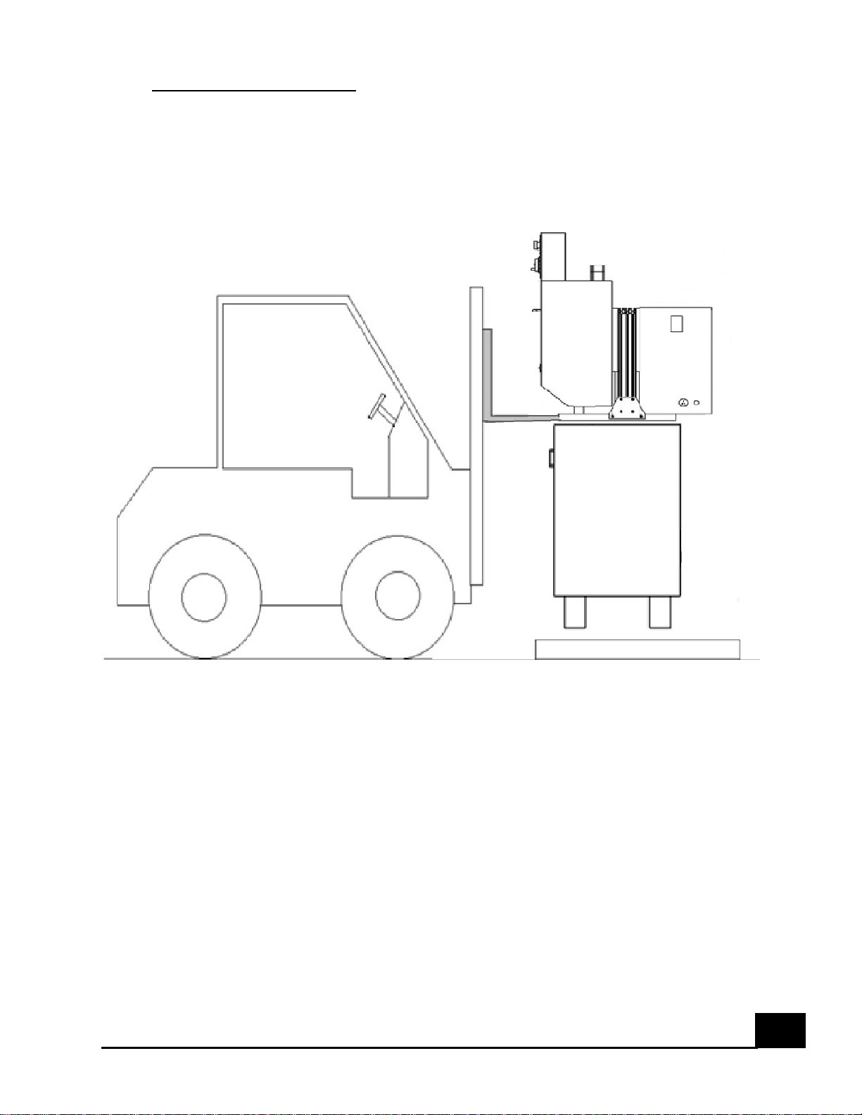
2) Use a forklift as depicted in Figure 8 to lift the machine and place it on top
of the Machine Stand.
Fig. 8 Proper way of lifting the machine
3) Secure machine to stand using screws provided on holes located on the legs
of the machine.
4) Roll machine to desired location.
5) Lower levelers located on the casters of the machine stand to make
machine more stable.
6) Connect the coolant and compressed air hoses. The machine should never
be used without a connection to a compressed air source.
7) Connect the power cord to a 110 VAC source.
TL-F20 CNC Lathe User’s Manual
Page 20

19
IV. Checkups during the Test Run
Before starting the machine for a test run, check the following:
1) Check that there are no missing parts or accessories.
2) Make sure the linear guide way tracks are well lubricated.
3) All hoses should be firmly connected to their respective connections and
there is no leakage of any kind
During the test run, turn the spindle at 1/2 of its maximum speed for about 20
minutes after the warm up. If there is any malfunction such as obvious
abnormal noise coming from the spindle or an alarm message in the control
screen, please contact the manufacturer for help.
TL-F20 CNC Lathe User’s Manual
Page 21

20
V. Relocation of the Machine
This machine was designed to be modular for easy transportation by one
individual without the need of a pallet jack or forklift if it is mounted on a
machine stand with casters. If it is desired to relocate the machine to another
room, the machine can be positioned such that it will fit through a door frame
of at least 34” wide. The following procedure should be used for proper
transportation of the machine from one room to the next.
1) If the machine is off, turn it on following the proper procedure.
2) Move the machine in the Z axis to the center of its travel.
3) Move the machine in the X axis down until the over-travel alarm is
activated.
4) Press the E-stop button on the Operator’s Panel.
5) Turn off the machine and disconnect the power cable.
6) Remove the compressed air hose connection and make sure there are no
other cables/hoses attached to the machine.
7) Release the leveling pads or brakes on the caster wheels.
8) Grab the stand base by its side and pull the machine.
9) Align the machine with the door frame and carefully pull the machine
through it making sure that the sides of the machine can go through
without hitting the side of the door frame.
10) When the machine reaches its final destination, apply the leveling pads or
brakes on the caster wheels located under the stand.
11) Connect the compressed air hose to the side of the machine.
12) Connect the power cord to a 110 VAC source.
13) The machine is now ready to be powered on again.
TL-F20 CNC Lathe User’s Manual
Page 22
21
4. Operation
I. Overview of the Operator Interface
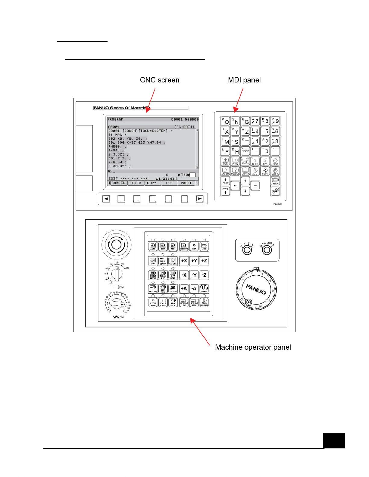
The operator interface includes three main components:
1) CNC Screen
2) MDI Panel
3) Machine Operator Panel
TL-F20 CNC Lathe User’s Manual
Page 23
22
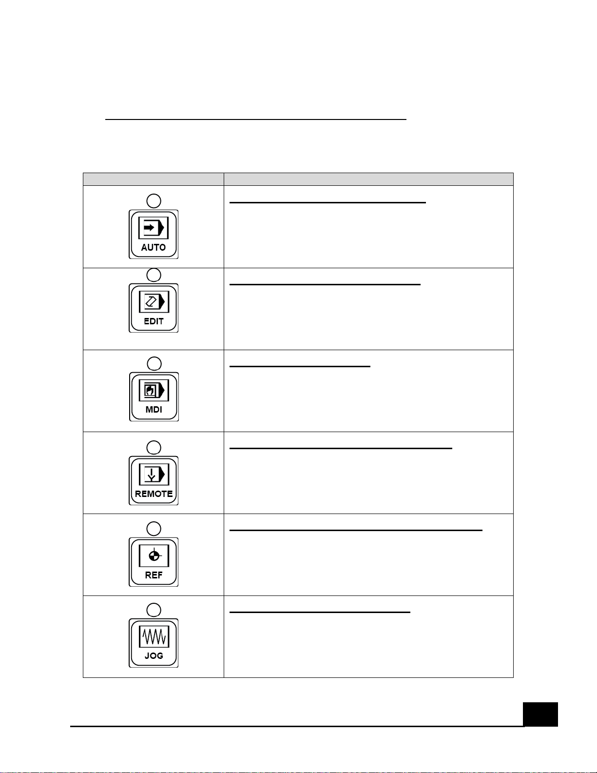
Button
Function
Auto Mode Selection Signal
Sets automatic operation mode. Used when running
codes automatically from the CNC memory.
Edit Mode Selection Signal
Sets program edit operation mode. Used to add/delete
codes into the CNC memory. Also used to make changes
manually to the code inside the CNC memory.
MDI Mode Selection
Sets the manual data input (MDI) mode. Used to
manually input data into the CNC
DNC Operation Mode Selection
Sets DNC operation mode. Used to run codes from the
Flash Memory port.
Reference Position Mode Selection
Sets reference position return mode. Used to move the
machine towards its home position only.
Jog Feed Mode Selection
Sets jog feed mode. Used to jog the machine using the
axis buttons located on the Operator’s Panel.
For information on the CNC screen and MDI panel, see the FANUC Series 0i-
MODEL D OPERATOR’S MANUALS. For information on the functions of the
Machine Operator Panel, see below.
II. Overview of Machine Operator Panel Functions
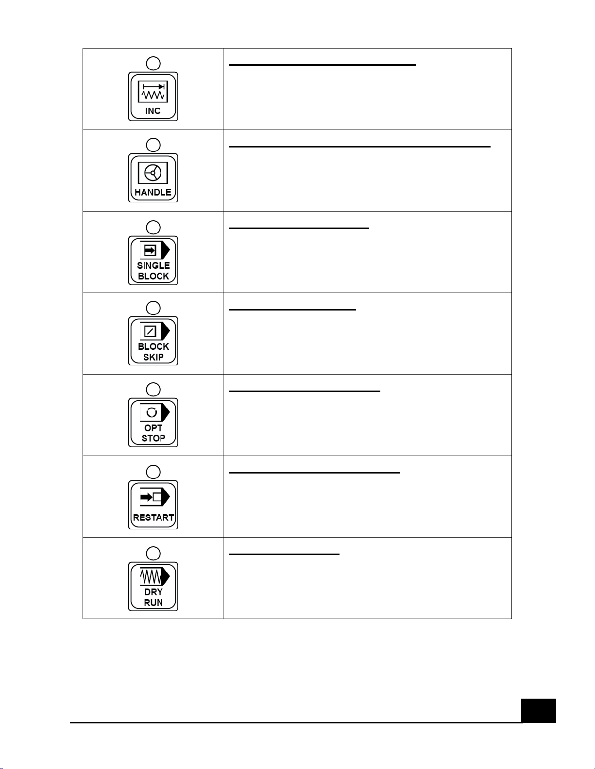
Table IV: Control module buttons and descriptions.
TL-F20 CNC Lathe User’s Manual
Page 24
23
Step Feed Mode Selection
Sets step feed mode. Used to move the machine in steps
when pressing the axis buttons in the Operator’s Panel
Manual Handle Feed Mode Selection
Sets manual handle feed mode. Used to move the
machine using the MPG (manual pulse generator) located
to the right side of the Operator’s Panel
Single Block Button
Executes program line by line, stopping at every line.
This key is used to check a program.
Block Skip Button
Pressing this button during automatic operation causes
the block under execution to stop, skipping to the end of
the block.
Optional Stop Button
Stops automatic operation after execution of the block of
a program where M01 is specified in the program.
Program Restart Button
A program may be restarted at a block by specifying the
sequence number of the block.
Dry Run Button
Sets the axis feed to the jog feed rate instead of a
programmed feed rate when automatic operation is
performed. This function is used to check the movement
of the tool when no work-piece is mounted.
TL-F20 CNC Lathe User’s Manual
Page 25
24
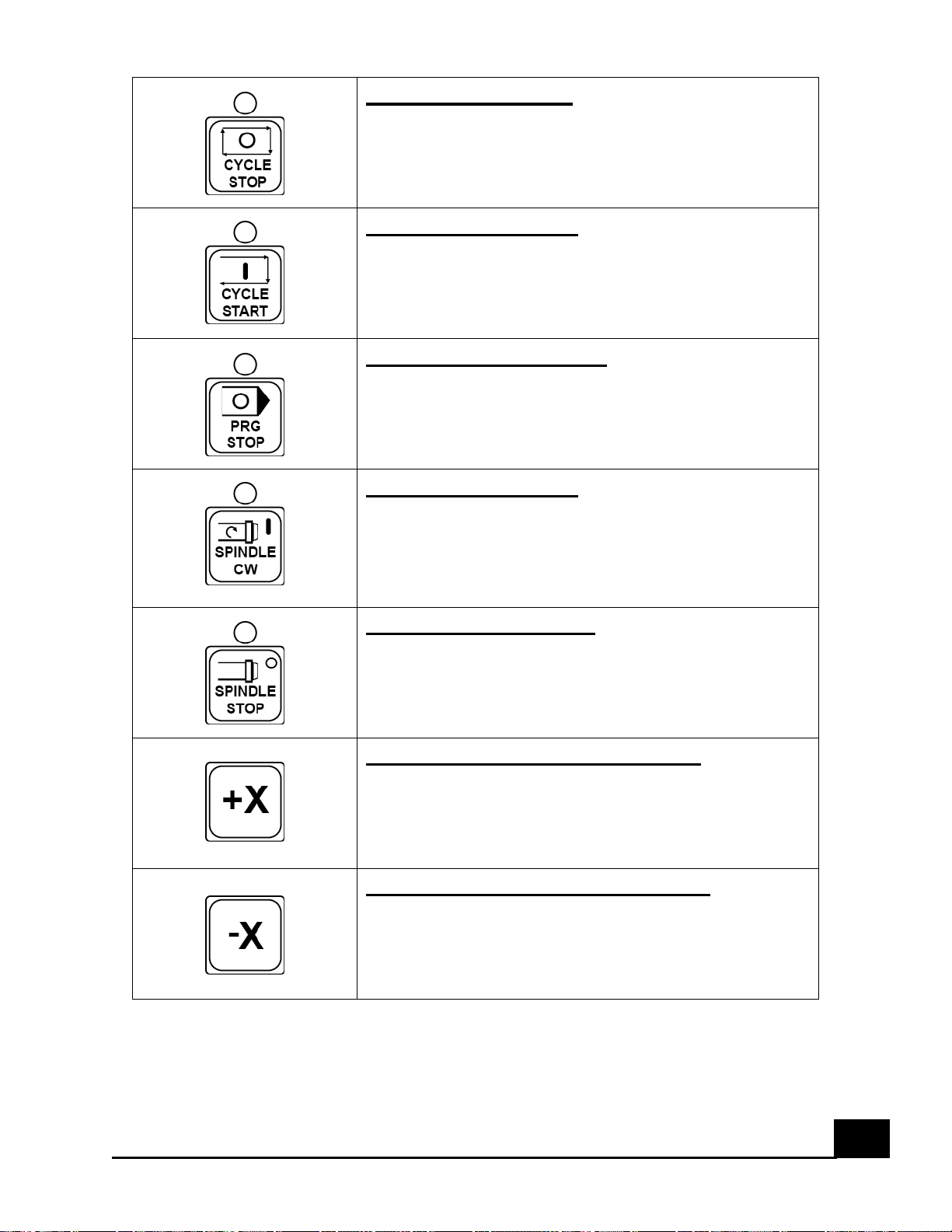
Cycle Stop Button
Stops automatic operation.
Cycle Start Button
Starts automatic operation.
Program Stop Button
Turns on the LED on the button when automatic
operation is stopped by M00 specified in the program.
Spindle ON Button
In manual mode, press this button to turn on the spindle.
Be sure to input an S value and an M3/M4 value,
otherwise spindle will not rotate. Change to MDI to input
or alter S value.
Spindle Stop Button
In manual mode, press this button to stop the spindle
rotation.
X-axis Positive Travel Button
In jog mode, press this button to move the spindle in the
positive X direction.
X-axis Negative Travel Button
In jog mode, press this button to move the spindle in the
negative X direction.
TL-F20 CNC Lathe User’s Manual
Page 26
25
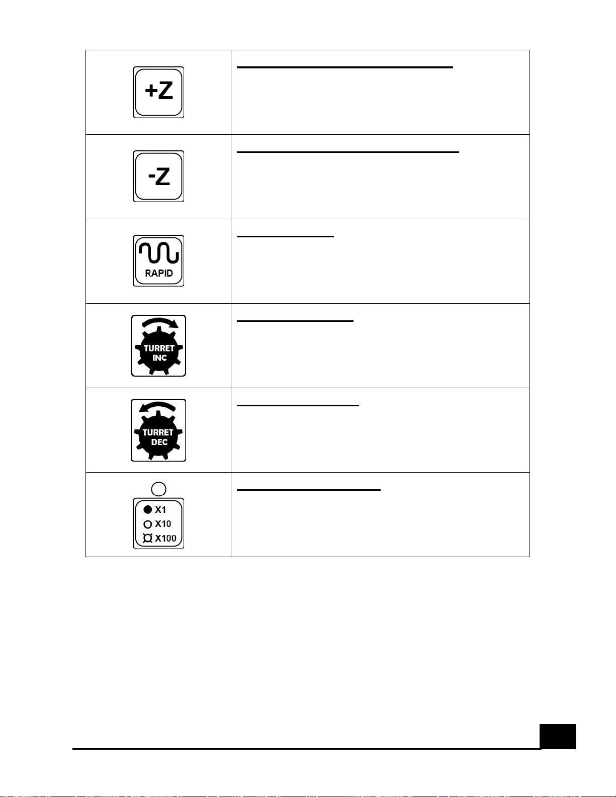
Z-axis Positive Travel Button
In jog mode, press this button to move the spindle in the
positive Z direction.
Z-axis Negative Travel Button
In jog mode, press this button to move the spindle in the
negative Z direction.
Rapid Button
Press an axis button and this button simultaneously while
jog mode is activated to move faster in said direction.
Turret Increase
Press the Rapid button and this button simultaneously
while in manual mode to change the tools in increasing
number
Turret Decrease
Press the Rapid button and this button simultaneously
while in manual mode to change the tools in decreasing
number
INC Amount Button
In Step Feed mode, press this button repeatedly to
switch between 0.1mm, 0.01mm, and 0.001mm intervals
in the selected axis travel.
TL-F20 CNC Lathe User’s Manual
Page 27
26
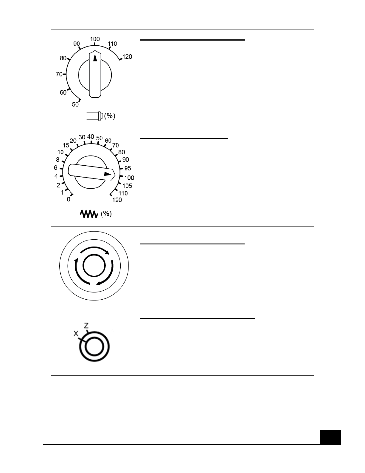
Spindle Speed Override
Manually adjust the spindle speed when rotating. The
changes are measured in the percentages of the initial
speed setting.
Feed Rate Override
Manually adjust the feed rate of the machine when
moving either manually or running a program. The
changes are measured in the percentages of the initial
speed setting.
Emergency Stop Button
Cuts the power to the servo motors and spindle when
activated. Press during an emergency or before
powering off the machine.
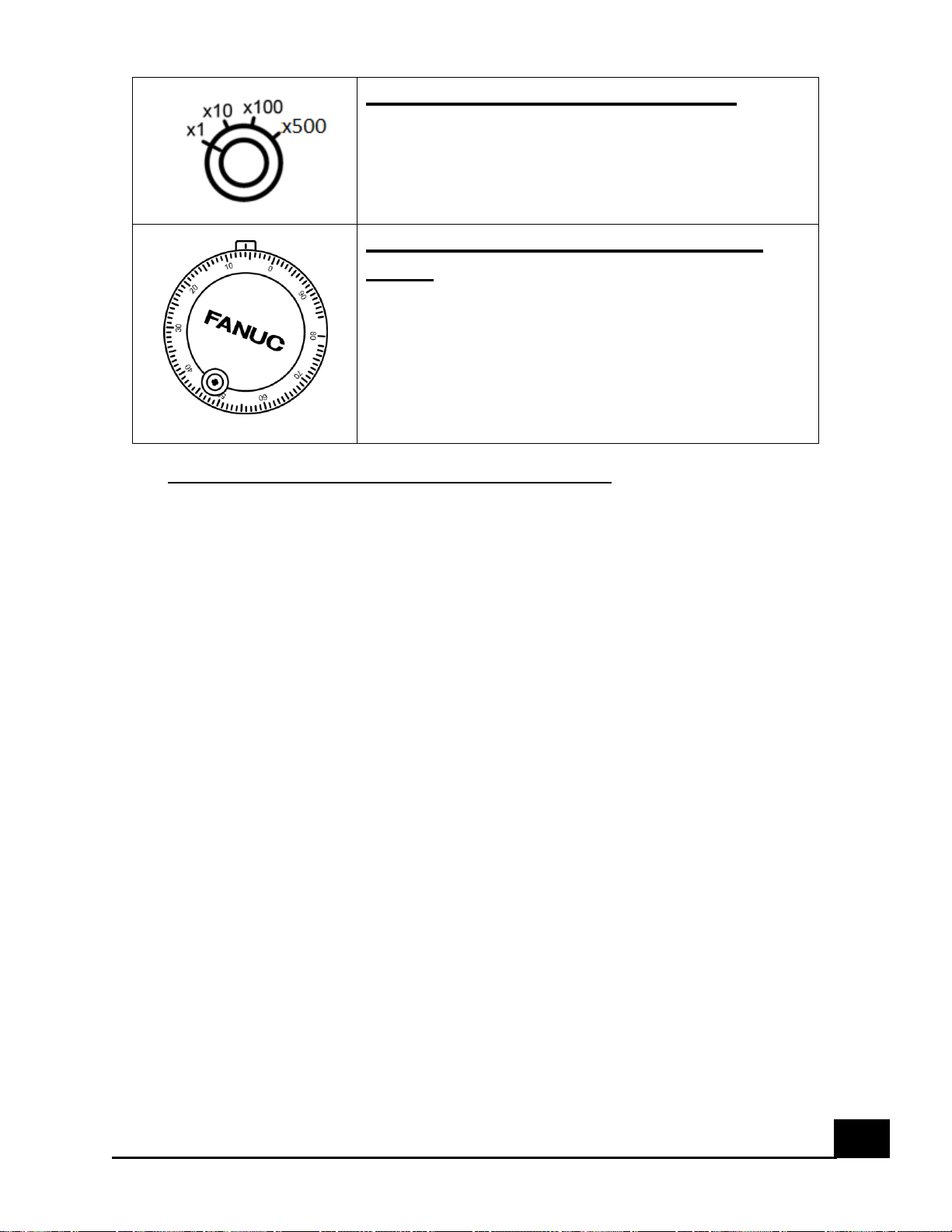
Handle Axis Select Switch
Selects the axis to move when using Handle Mode
TL-F20 CNC Lathe User’s Manual
Page 28
27
Handle Increment Select Switch
Selects the step increment (0.001, 0.01, 0.1 and 0.5
intervals) when using Handle Mode
Handle or Manual Pulse Generator
(MPG)
Moves an axis in the Increment mode and Axis mode
selected when in Handle Mode
III. Machine Start Up and Shut Down Procedure
In order to turn on the machine safely, the following instructions must be
followed. You will run th01e risk of damaging the machine/internal
components if this procedure is not followed.
1) Press the E-stop button to activate it. The E-stop button is a bright red
button located on the Operators Panel.
2) Connect the power cable into a 110 VAC outlet.
3) Switch the Main Power switch to the ON position.
4) Wait for the CNC to boot up and then release the E-stop button when
prompted with the EMERGENCY alarm.
The machine is now ready to be used. It is important to always perform a
warm up of the machine before daily use.
When the machine is ready to be turned off, please follow the following
procedure.
1) Send the machine to its home position on the Z axis by selecting the REF
button on the Operator’s Panel and pressing the +Z button until the
machine reaches its home position.
2) Press the E-stop button to activate it.
3) Switch the Main Power switch to the OFF position.
TL-F20 CNC Lathe User’s Manual
Page 29
28
IV. Spindle Operation
Spindle operation is very simple on this machine. Simple commands must be
loaded into the control in order to begin spindle operation.
CAUTION!
The spindle should always be warmed up before daily use or else you run the
risk of lowering the spindle bearing’s life. The process should begin by rotating
the spindle at 1,000 rpm for 10 minutes and then speeding up to 1,500 for
another 5-10 minutes.
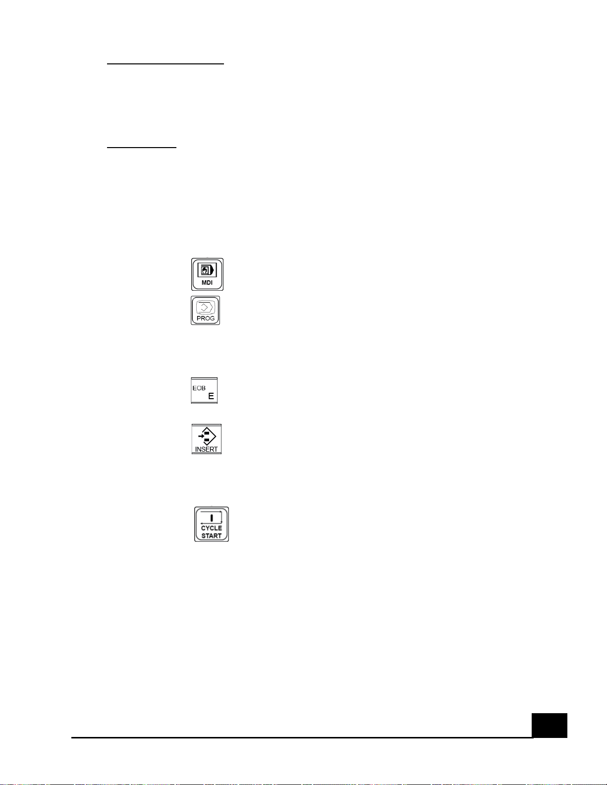
Please follow the procedure when attempting to operate the spindle manually.
1) Press the button on the operator’s panel.
2) Press the key in the MDI panel to navigate to the manual data input
page on the CNC.
3) Write the following “S1000 M3” using the MDI Panel.
4) Press the key to finish the line command that you are about to load
into the control. It should read “ S1000 M3 ; ”
5) Click the key and notice the line command being loaded into the
control.
6) Make sure that the spindle chuck is tightened and that the T handle has
been removed from the chuck.
7) Press the button on the Operator’s Panel and notice the spindle
begins rotating at 1000 rpm. Make sure the door is closed so the safety
sensor makes contact or else the machine will not run the command.
The letter “S” tells the control that you are about to give a “Spindle” command
which is followed by a number (in our case we chose 1000) which denotes the
desired spindle speed or rpm. The code “M3” tells the machine to turn on the
spindle in a clockwise direction.
TL-F20 CNC Lathe User’s Manual
Page 30

29
The spindle can be manually turned ON/OFF using the SPDL FWD and SPDL
STOP buttons on the Operator’s Panel; however an initial spindle speed and
direction must be loaded into the control beforehand.
The spindle speed can be adjusted manually while the spindle is rotating by
using the Spindle Override knob located on the Operator’s Panel. The speed
can be adjusted from 50% to 120 % of the loaded spindle speed in increments of
10%.
The spindle uses pressurized air for cooling purposes and pressurization
purposes.
WARNING!
Always have air running through the spindle when using the machine. Never run
the spindle and/or coolant without having any air flowing through the spindle.
The pressurized air enters through the top side of the spindle headstock and
exits through small openings all around spindle nose. The pressurized air should
be no less than 90 PSI and no more than 120 PSI. There is an adjustable flow
valve that limits the amount of air flowing through the spindle. The valve is
located above the headstock. In order to reach the valve, a side cover must be
removed from the right side of the machine.
TL-F20 CNC Lathe User’s Manual
Page 31

30
V. Setting the Work-piece Coordinate System
Any time a new work-piece is placed in the machine, its coordinate system
offsets values (or the work-piece's "zero" position) must be measured so that
the CNC can locate its exact position. The following procedure is a brief guide
to ensure proper work piece set up.
1) Secure a work-piece in the spindle chuck to ensure it will not move
during the measurement and machining process, while still ensuring there
is enough space from the end of the work piece to the chuck jaws to
machine the part.
2) Inspect the work-piece edges to make sure there are no burrs or other
imperfections that may cause a false edge reading. If there are, use a file
or manual deburring tool to smooth out the edges.
3) Make sure the tool turret is clear of the spindle chuck and work piece in
order to perform a tool change (Send the machine to its home position).
4) Rotate the tool turret so an external tool is placed on the active tool slot.
5) Start the spindle at 1000 rpm.
6) Move the tool in the Z axis and X axis until the tip end is just barely
touching the work piece’s outer face in the Z axis and edge on the X axis.
7) Move the tool one increment (0.1 mm or 0.01") into the work piece and
then move in the X axis down to even out the outer face of the work
piece.
8) Turn off the spindle.
9) Select a point of reference on the tool turret to use for measuring the Z
axis position (ie. Cutting tool tip of tool #1).
10) Move the tool turret in the Z axis until the reference point chosen
touches the outer face of the work piece.
11) Press the key and then the [WORK] soft key on the control panel
to display the Work Offsets page. Navigate to the frame of reference
used in the program for this work-piece. Frames of reference vary from
G54 to G59.
12) Each frame of reference has one numeric value for each axis. Highlight
the Z axis and write "Z0” followed by the [MEASURE] soft key.
13) The X axis home position is preset at the factory at 160 mm or 6.2992”
from the spindle center. The X axis should read -160 mm or -6.2992” on
the X position for each frame of reference.
14) If multiple copies of the same work-piece are to be machined, mark the
position of the measured work-piece so as to place the next part in the
same position.
TL-F20 CNC Lathe User’s Manual
Page 32

31
VI. Setting Tool Length Offset
Before a new tool can be used, its tool length offset must be measured so the
machine knows how long the tool is. Please follow this procedure when
attempting to measure tool length offset:
1) Set up the work piece coordinate system and activate it.
2) Move the tool turret to the home position.
3) Position the desired tool in the active cutting position.
4) Using the handle or jog mode, move the tool towards the outer edge of
the work piece until it touches the work piece.
5) Press the key followed by the [OFFSET] soft key to display the tool
offsets page.
6) Using the arrow buttons on the control panel, navigate through the
screen and highlight the GEOM (H) position for the corresponding tool
number. Write "Z" and press the [INP.C] soft key to store the difference
in length between the reference tool and the tool being measured.
7) Position the tool turret so the tool can barely cut the work piece in the X
axis.
8) Start the spindle at 1,000 rpm.
9) Move in the Z axis and cut the work piece enough so the new diameter
can be measured with a caliper or micrometer.
10) Move in the positive Z axis to move away from the work piece. Do not
move in the X axis.
11) Turn off the spindle.
12) Measure the diameter of the work piece.
13) Press the key and then the [WORK] soft key on the control panel
to display the Work Offsets page. Navigate to the frame of reference
used in the program for this work-piece.
14) Highlight the X axis and write "X#” followed by the [MEASURE] soft key.
The # represents the diameter measured from the work piece.
15) Return the tool turret to its home position.
16) Repeat steps 6 through 9 for any additional tools.
TL-F20 CNC Lathe User’s Manual
Page 33
32
VII. Automatic Tool Change Operations
The tool change system works by rotating the tool turret disk clockwise or
counter-clockwise. Before rotation of the tool turret disk is performed, the
tool turret must be moved away from the spindle chuck to clear any tools that
might hit the spindle chuck as they rotate.
In this machine you can change tools manually and automatically. The
procedures below must be followed in order to properly perform a tool change
without damaging any components of the machine.
CAUTION!
The inside cutting tools such as boring bars or drill bits will hit the spindle
when the tool turret disk is rotated if they have not been moved clear of the
spindle chuck. Move the machine towards its home position in both the X and Z
axis before performing any tool changes.
1) Send the machine to its home position on the X and Z axis.
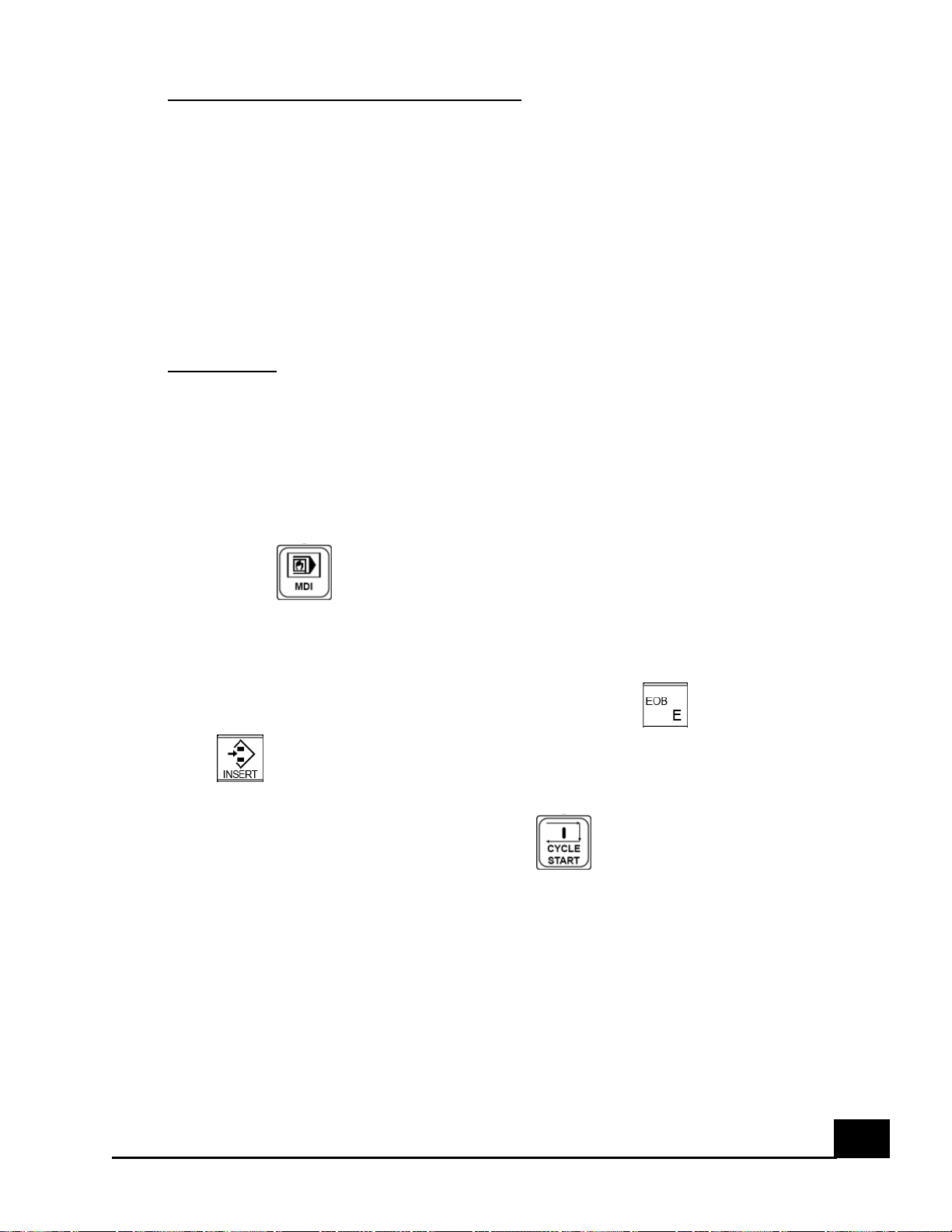
2) Select mode, then on the program window, input "T####”. The
first two pound signs represent the tool number and the last two
represent the tool number offset (i.e. T202 selects tool number 2 and
offset 2).
3) Once the line of command is ready, press the key followed by
key. The line command should read “T101;” if choosing tool
number 1 for the tool change.
4) To initiate the tool change, press the button.
To change tools manually, set the machine to either handle or jog mode and do
the following:
1) Send the machine to its home position on the X and Z axis.
2) Turn off the spindle if it is rotating.
TL-F20 CNC Lathe User’s Manual
Page 34

33
3) Press and hold the button or the and the button
simultaneously to activate the tool change mechanism in the clockwise
direction (Increasing tool number)
4) Press and hold the button and the button simultaneously to
activate the tool change mechanism in the counter-clockwise direction
(Decreasing tool number)
TL-F20 CNC Lathe User’s Manual
Page 35

34
VIII. Coolant System Operation
The machine is equipped with a coolant system which consists of the following
components:
1) 6 gallon coolant reservoir.
2) 115 V @ 60 Hz, 1/20 hp submersible pump.
3) Chip Collector.
4) Hoses to and from the machine.
All the internal components will be fitted by the manufacturer. The external
components such as hoses and hose clamps must to be attached by the user.
Once the hoses have been attached, they do not need to be removed unless
they need to be exchanged.
It is recommended that the coolant of choice be semi-synthetic and designed
to work best for the material to be cut by the machine. There are some fully
synthetic coolants that can be corrosive towards plastic parts such as O-rings
located on many components of the machine which is why the use of synthetic
coolants is not recommended.
The coolant system is turned on and off directly from the operators panel, or
via the commands M08 and M09 through the machine control’s MDI.
Please follow the procedure below to operate the coolant system.
1) Select a manual mode in the operator’s panel (Jog, Handle, Ref).
2) Press the button in the operator’s panel to activate the coolant
(LED should turn on).
3) Press the button again in the operator’s panel to deactivate the
coolant (LED should turn off)
TL-F20 CNC Lathe User’s Manual
Page 36

35
5. Maintenance
Never perform any maintenance work on the machine while it is powered on
unless it is required. If power is required, press the emergency button and tag
out the machine before performing any maintenance or inspection work on the
machine.
I. APC warning and “DS0300 APC alarm: Need Ref Return”
This machine is equipped with absolute encoders which mean that they will
remember their position even if the machine’s power is turned off. This is
accomplished by a battery pack which is connected to one of the servo drives
located inside the machine’s modular stand.
If the battery is running low on power, the CNC screen will flash an “APC” message
with yellow background. At this point, the power on the machine should stay on until
the batteries have been replaced.
Should the battery die before it is replaced, the position of each servo will be lost and
the alarms “DS0300 APC alarm: Need Ref Return” and “DS0306 APC Alarm: Battery
Voltage 0” will be shown on the CNC screen for each axis.
A replacement battery pack can be obtained through FANUC America’s Parts
Department (1-888-FANUC US (select-2→1→1)) using the part number A98L0031-0025.
CAUTION!
The following procedure must be used in order to correctly set each servo’s
Home Position.
If the batteries are being replaced due to the flashing APC warning denoted by
the letters APC with a yellow background on the CNC screen, and no alarms
(DS0300 or DS0306) have been issued by the CNC control, only follow steps 2-5
without turning off the power to the machine.
If the alarms DS0300 and DS0306 have been issued by the CNC control, follow
the entire procedure.
The following procedure should be done by a qualified technician.
1) Follow the Shut Off procedure, disconnect the power cord and tag it out.
2) Open the electrical enclosure located in the back of the machine.
TL-F20 CNC Lathe User’s Manual
Page 37
36
3) Locate the battery pack mounted on the servo drive (Battery pack will be
hidden by a grey cover)
4) Replace the battery pack (P/N A98L-0031-0025).
5) Close the electrical enclosure
6) Plug the power cord into 110 VAC and turn on the machine.
7) Once booted up, release the E-stop button.
8) Place a dial indicator in the spindle chuck
9) Perform a tool change so a boring bar tool holder is in the active tool
cutting slot. Remove the boring bar if it is on the boring bar holder.
10) Move the machine on the negative X-axis and eye ball centering the
boring bar tool holder with the spindle.
11) Use a dial indicator to measure the inside of the boring bar tool holder
and adjust the error between both centers.
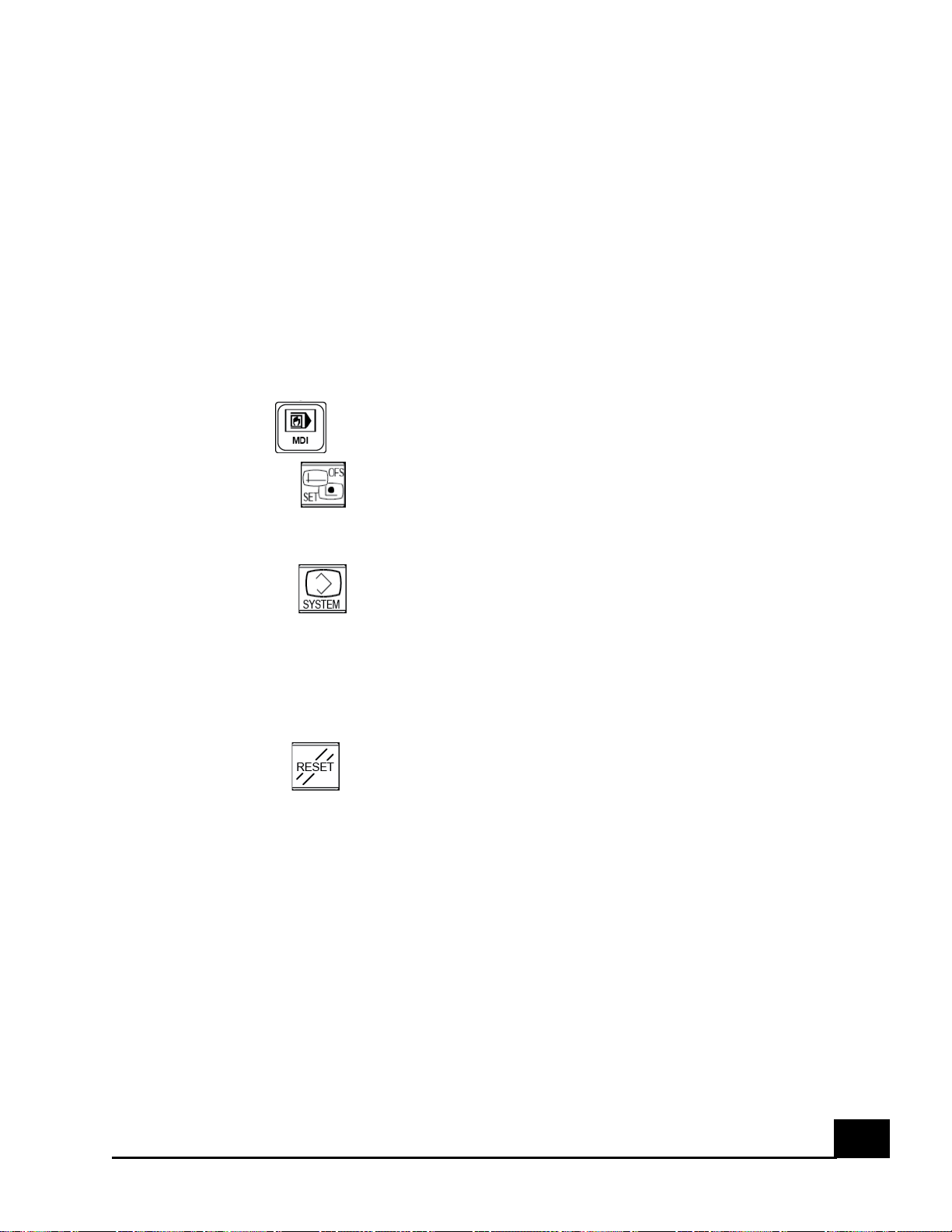
12) Select mode.
13) Press the function key on the MDI panel.
14) Press the [SETTINGS] soft key.
15) Input a 1 on the Parameter Write option.
16) Press the key on the MDI panel.
17) Using the right arrow soft key, search for the [PARAM] soft key.
18) Write 1815 using the number keys.
19) Press the [SEARCH] soft key.
20) Using the arrow keys, highlight bit #4 (APZ) in the X axis.
21) Input a number 1.
22) Press the key.
23) Activate the E-stop button.
24) Reboot the machine.
25) For the Z axis, remove the cover plate located to the right of the turret (The Z
axis servo will become visible).
26) Move the Z axis in the positive direction until the guide way linear block is 11
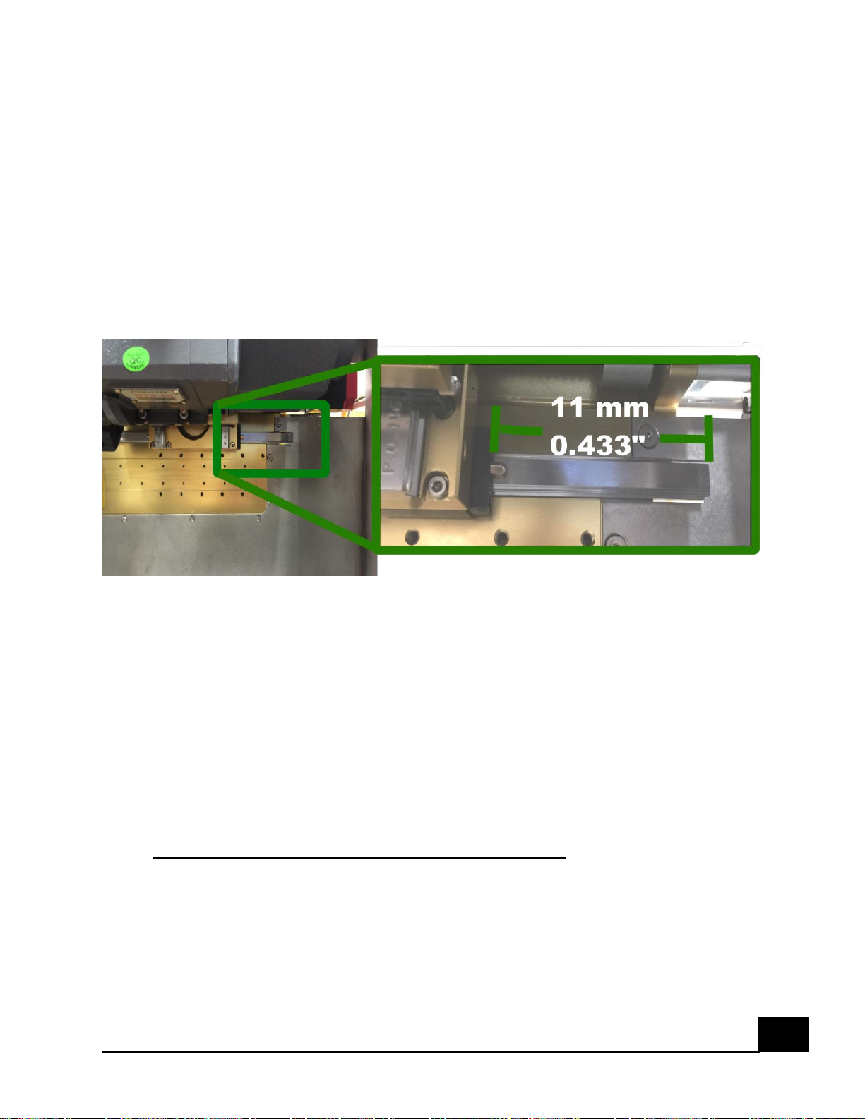
mm (0.433”) away from the linear guide way end. Image 2 below shows how to
measure the distance.
27) Repeat steps 16 through 24.
28) The axis reference position alarm should no longer appear.
TL-F20 CNC Lathe User’s Manual
Page 38
37
Image 2. Setting the Z-axis home position
II. Aligning the spindle head and the tool turret
If the tool turret or spindle head is moved either for maintenance reasons or
due to a crash, the alignment of either will need to be re-set. The alignment
position is measured from the center of the spindle to the center of the
TL-F20 CNC Lathe User’s Manual
Page 39

38
external tool holder mounted on the tool turret. Please follow the procedure
below to ensure proper alignment of both systems.
For the alignment of the tool turret, please use the following procedure:
1) Mount a dial indicator with a magnetic base on the Z-axis guide ways.
2) Measure the 3 o’clock face of the tool turret disk where an external tool
sits by moving in the Z axis. If there is an error higher than 0.01 mm
(0.0004”), adjust its position using shimmies (at the top 2 or bottom 2
screws that hold the tool turret) until there is less than 0.01 mm
(0.0004”) of error between the left and the right side of the tool turret
disk.
3) Tighten the screws of the tool rack and re-measure.
4) Loosen 3 screws and leave the 4
th
screw semi-tight.
5) Repeat steps 2 and 3 measuring the 6 o’clock face of the tool turret disk
along the Z axis. Do not use shimmies, only rotate the tool turret.
6) Follow the APC warning and “DS0300 APC alarm: Need Ref Return” procedure
to set the X axis home position.
For the alignment of the spindle, please use the following procedure:
7) Place a dial indicator on the tool turret and a straight cylinder on the
spindle chuck.
8) Measure the top side of the cylinder by moving back and forth on the Z
axis.
9) Remove the cover on the left side of the machine to gain access to the
spindle. The spindle base uses 4 set screws that are used for alignment
and four screws used to keep the base in place.
10) Loosen the 4 holding screws and use the 4 set screws to rotate the
spindle head base to decrease the error until there is less than 0.01 mm
(0.0004”)
11) Tighten the holding screws and measure the cylinder to check the
alignment.
12) Follow the APC warning and “DS0300 APC alarm: Need Ref Return” procedure
to set the X axis home position.
The tool turret and spindle are ready to be used again.
III. BTP-50 Tool Turret Maintenance
TL-F20 CNC Lathe User’s Manual
Page 40

39
The BTP 50 tool turret is a self contained tool change system. The system
should be checked out periodically to make sure that everything is working
without problems. Please read the BTP-50 User’s manual included to take
proper care of the system.
Due to the design of the turret, oil changes cannot be performed while it is
mounted on the machine, therefore the system will need to be removed.
For an oil change, remove the 4 screws holding the turret and flip it 90
degrees. If a base (2 2x4 pieces of wood placed on the work area floor to raise
the floor) is added to the floor of the machine, there are two hoses attached to
the turret that will not need to be removed. Carefully place the turret on the
base and perform the oil change. When ready to place the tool turret back
into its position, place the bottom two screws first, then mount the turret on
the screws and place the top two screws. It is recommended that two people
are used for this operation.
TL-F20 CNC Lathe User’s Manual
Page 41

40
IV. Ball Screw Lubrication Procedure
The ball screw nut requires lubrication to maintain proper friction between the
bearings and the ball screw. The ball screw nut is surrounded by a liquid
absorbent material on both openings of the ball screw nut base which is soaked
in oil during the machine assembly process and will maintain the ball screws
lubricated for a while before they require lubrication again.
Re-lubrication of the oil absorbent material should be done every 1 to 2 weeks
when the machine is in use daily. If the machine will sit idle for long periods of
time, a coating of oil should be applied every time the ball screw feels dry.
To re-lubricate, add a coat of oil (lithium based, 30-140 cst, ISO 32-100) all
over the ball screw and slowly move the axis back and forth throughout its
entire travel length so the oil absorbent material can soak in the oil. Fast
movement will cause the oil to fly all over. After the process is done, clean up
the excess oil.
To gain access to each ball screw, three covers will need to be removed which
are attached to the tool turret base on the X-axis.
TL-F20 CNC Lathe User’s Manual
Page 42

41
V. Linear Guide Way Lubrication Procedure
Linear guide way lubrication is important for maintaining the function of linear
guide ways. If the lubrication is not sufficient, the frictional resistance at
rolling area will increase and the service life will be shortened as a result of
wear of rolling parts.
There are four linear blocks per axis on the X and Z axis. Each linear block has
a fitting located on one of its sides. Access to the fittings requires little or no
removal of machine parts.
Two primary lubricants are both grease and oil used for motion systems.
Grease lubrication should be done with a lithium based grease No. 2 and should
be applied every 100 Km of travel. Moving each axis for 150 mm back and forth
after the grease has been applied to all four linear blocks will ensure proper
distribution of the grease.
Oil lubrication should be done with an oil of viscosity 30-150 cst in intervals of
1 to 2 weeks when the machine is used daily.
To gain access to each linear guide way and linear block, three covers will need
to be removed which are attached to the tool turret base on the X-axis.
TL-F20 CNC Lathe User’s Manual
Page 43

42
VI. Servo Adjustment
The servo motors for the X and Z axes are positioned in a direct drive
configuration attached to the ball screws by a shaft coupling. If the machine is
commanded to move but it is noticed that the actual distance moved is less, or
the home position of the machine seems to be changing, it could mean that the
servo or ball screw is slipping inside the coupling. Check to make sure that the
shaft coupling is tightened on both sides (servo and ball screw) to make sure
that neither shaft keeps slipping.
The home position will need to be reset for the axis in question. Please follow
the APC warning and “DS0300 APC alarm: Need Ref Return” section to safely
set up the home position.
TL-F20 CNC Lathe User’s Manual
Page 44

43
VII. Cleaning the Machine
It is recommended to clean the machine’s work area at the end of the day
after it has been used and to give a thorough cleaning once a week.
DO NOT blow air into the working area as small shavings can become encrusted
in between moving parts such as the tool turret.
To remove the shavings, move the tool turret to its home position on the X
axis. Most of the shavings can be removed by hand and the smaller shavings can
be removed using a wet/dry vacuum.
There is an exit nozzle on the stainless steel tub located to the right side of the
work area. This exit has a mesh that will keep the shavings from escaping
through the nozzle. Make sure to routinely clear the mesh after long periods of
use to keep it from becoming clogged or else the coolant might not flow
properly back to its reservoir.
It is recommended to give the machine a thorough cleaning once a week if used
daily or once a month if used a couple of times a week. Removing the 3 covers
located behind the tool turret on the X-axis will give access to the ball screws
and linear guide ways. Make sure to remove all the small shavings that might
hide behind the covers around the ball screws and linear guide ways.
TL-F20 CNC Lathe User’s Manual
Page 45

44
VIII. Coolant system
The coolant must be kept at a certain concentration range. Ask your coolant
provider for specifications. Coolant must be replaced at least once or twice a
year or in accordance to the manufacturer specifications.
If the coolant system will not be used over a long period of time, the coolant
pump should be taken out of the coolant and placed in a tub with clean water.
Have it run for a couple of minutes to ensure the coolant is completely
removed from the inside of the pump. Coolant left inside the pump while it is
sitting idle may dry and cause the pump to stop working properly.
TL-F20 CNC Lathe User’s Manual
Page 46

45
IX. Wiring Diagrams
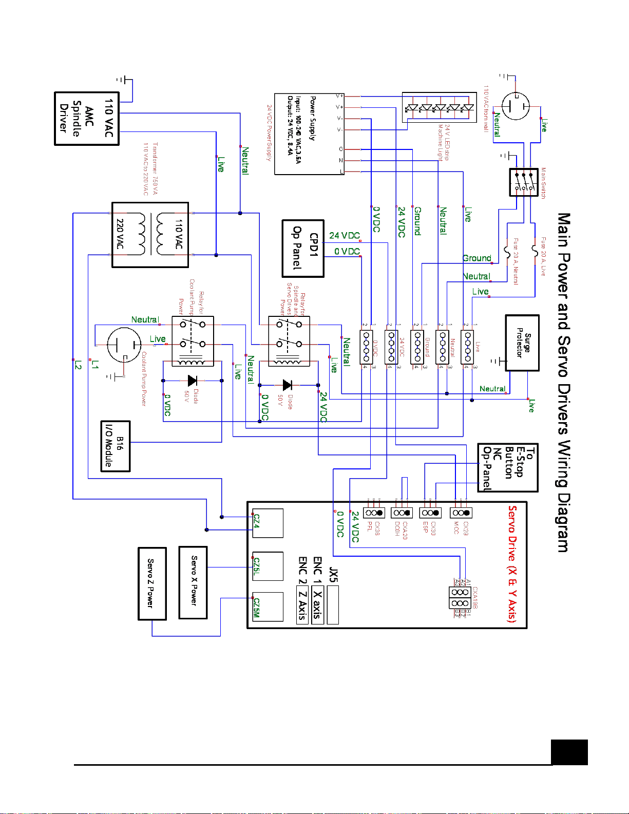
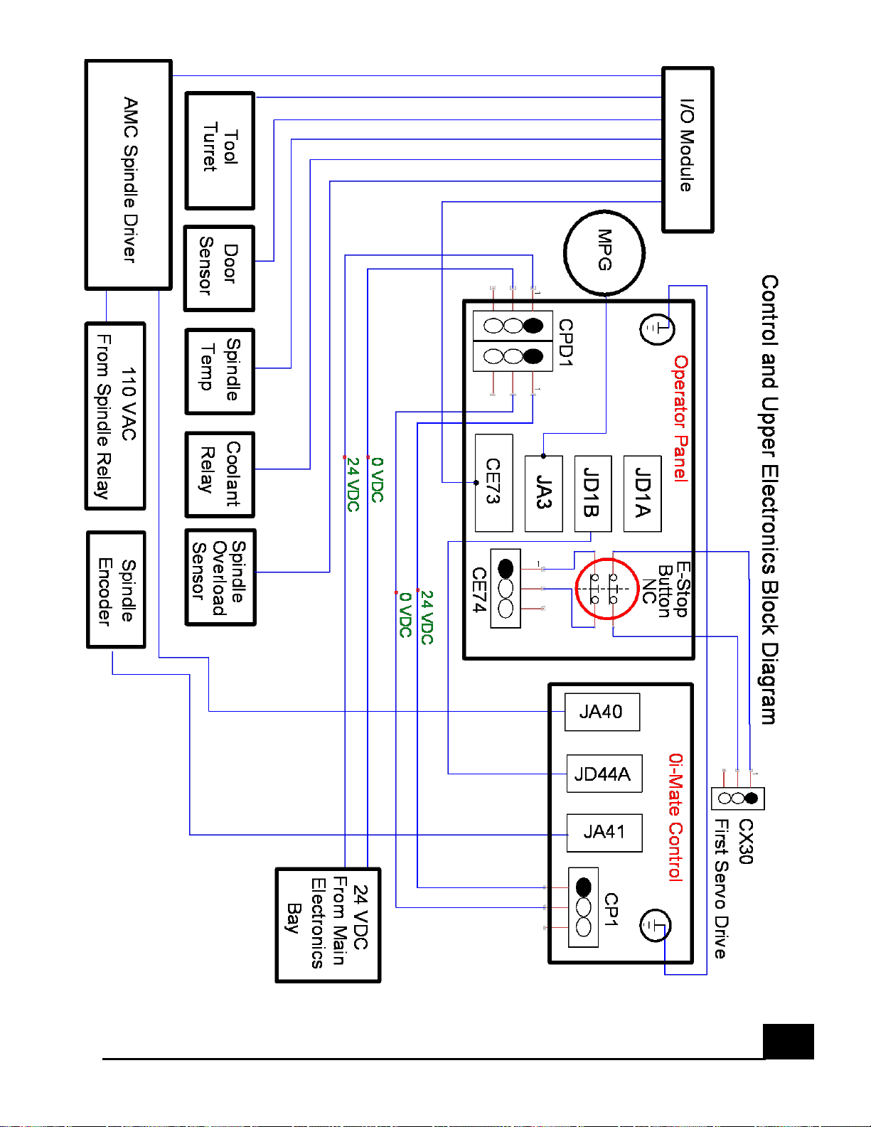
The wiring in this machine is divided between three sections. The first area is the Main
electronics bay which is located inside cabinet behind the machine. It contains the main power
controls and the servo drives for the FANUC control. The second area is located inside the
FANUC control case where the control, operator panel and input/output module are located.
The third area is the Spindle electronics bay and is located on the left side of the machine, above
the spindle head. This area contains the spindle driver and tool turret driver as well as the
spindle motor.
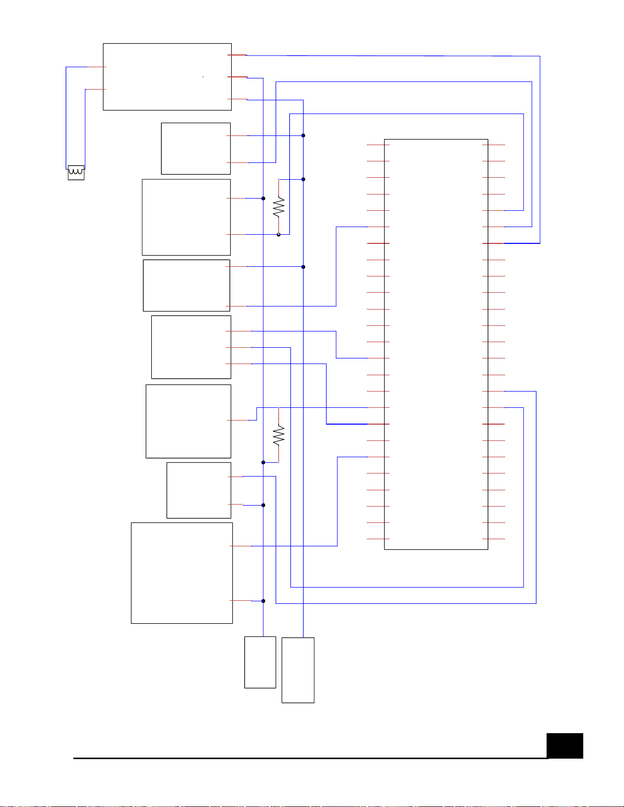
The following diagrams represent the wiring schematics of the machine.
TL-F20 CNC Lathe User’s Manual
Page 47
46
TL-F20 CNC Lathe User’s Manual
Page 48
47
TL-F20 CNC Lathe User’s Manual
Page 49
48
24 VDC
1
0 VDC
2
Overload Signal
3
Spindle
Overload
Sensor
24 VDC
1
0 VDC
2
0 VDC
1
24 VDC
2
Tool Length
Sensor
Inhibit In 9
A-M-C
Spindle Driver
0
1
1
2
Coolant
Relay
24 VDC
1
Temp Signal
2
Spindle
Temp
Sensor
24 VDC
1
Signsal
2
Door
Sensor
A
B
0 V
1
Reserved
2
Reserved
3
Reserved
4
Reserved
5
Spindle Temp
6
Probe Batt Low
7
E-Stop
8
Open
9
Turret Bit1
10
Turret Bit 3
11
Turret Strobe
12
Turret Clamp
13
Turret Inverter 0 V
14
Reserved
15
Open
16
Spindle On
17
Turret REV
18
Open
19
Sensor Light
20
Open
21
Open
22
Open
23
Open
24
Open
25
24 V
1
Reserved
2
Reserved
3
Reserved
4
Sensor Skip Signal
5
Door Sensor
6
Spindle Overload
7
Open
8
Reserved
9
Turret Bit 2
10
Turret Bit 4
11
Turret Parity
12
Turret Motor Temp
13
Connect to A1
14
Rserved
15
Coolant
16
Turret FWD
17
Tail Stock Activate
18
Probe On
19
Open
20
Open
21
Open
22
Open
23
Reserved
24
Reserved
25
PLC
1
2
3
Turret
Inverter
HITACHI
1
2
Sensor Active
1
0 VDC
2
Tool Length
Sensor Light
0 VDC
24 VDC
I/O Module Wiring Diagram For TL-F20
Overload Sensor
1 K1 K
TL-F20 CNC Lathe User’s Manual
 Loading...