

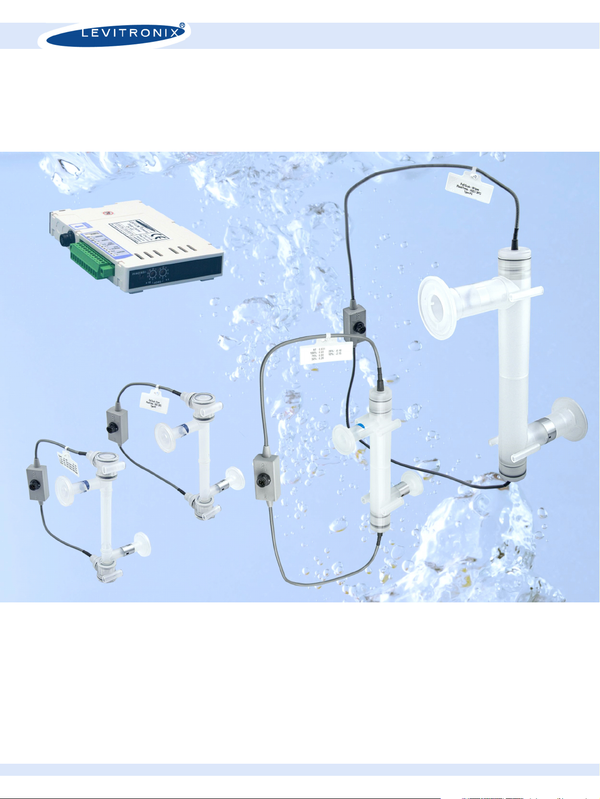
LEVIFLOW® Ultrasonic Technology
Single-Use High Precision Flowmeters
LFS-SU Single-Use Flowmeters
LFS-03SU: 0 – 0.8 l/min LFS-06SU: 0 – 8 l/min
LFS-10SU: 0 – 20 l/min LFS-20SU: 0 – 80 l/min
Ultraclean Non-Invasive Flow Measurement
ULTRASONIC FLOW MEASUREMENT
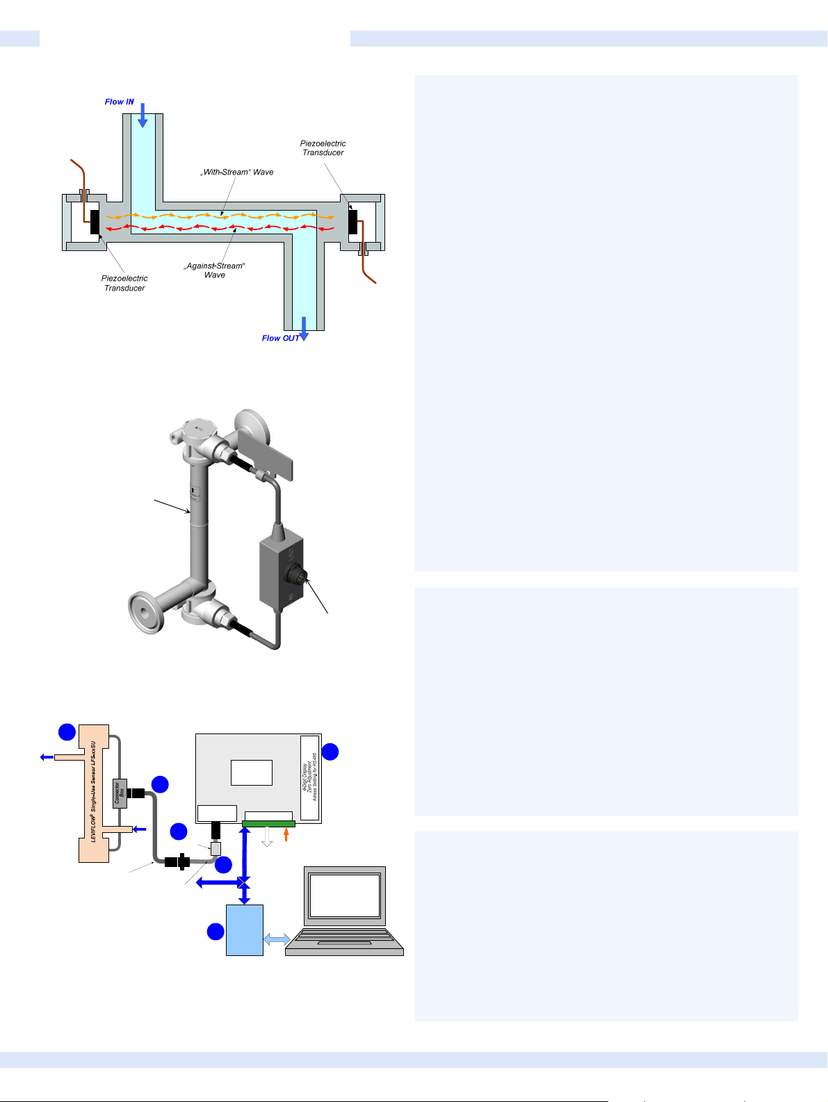
Figure 1: Operating principle of ultrasonic single-use sensor
Measurement Path
INTRODUCTION
The LEVIFLOW® single-use flowmeters are designed for non-
invasive flow measurements of high purity fluids with flexible
tubing. Figure 1 illustrates the operating principle. Two piezo-
electric transducers, mounted in the sensor housing, generate
and receive an ultrasonic wave. The wave going in direction of
the flow (with-stream wave) is accelerated and the wave going
against the flow direction (against-stream wave) is slowed
down. The two waves are processed by a signal converter. The
difference of the transit time of both waves is proportional to the
velocity of the fluid. The wet materials of the single-use sensors
fabricated from biocompatible (FDA, USP-VI, BSE/TSE and
Animal free) gamma sterilizable polypropylene (PP).
The standard configuration of the LEVIFLOW® single-use
flowmeters (Figure 3) consists of a flow sensor and a converter
with a digital signal processor (DSP) for processing the sensor
signals. Various signals (analog output, digital input/output) are
provided and can be configured with a PC software. A two wire
RS485 bus allows arrays of multiple flowmeters. In addition, the
sensor value is shown on a 4-digit display. For debugging, data
collection and configuration with a PC the LEVIFLOW®
Configuration Software is available at Levitronix® together with a
USB to RS485 adaptor (see Figure 3).
Figure 2: Single-use flowsensor
1
Flow Out
Flow In
Interconnect Cable
Various lengths.
Direct connection possible.
Adaptor/Extension Cable
Wallmountable connector
for cabinet mounting
Figure 3: System configuration for usage with LEVIFLOW®
configuration software
3a
2b
EMI Ferrite
Single-Channel Converter LFC-1C-PC
Digital
Signal Processor
DSP
Piezo Transducers
In-/Output
Other RS485
Devices
Electrical Interface
3b
RS485
(MODBUS)
BUS
Converter
4
RS232/RS485
or
USB/RS485
Analog and
Digital Outputs
- 1x Analog Output
- 2x Digital Outputs
- 1x Digital Input
RS232 or USB
Power Supply: 24 VDC
Configuration Software
Watertight
Connector
Box
2a
®
LEVIFLOW
SYSTEM BENEFITS
High precision (1%) flow measurement
No contamination due to non-invasive flow measurement
No moving parts -> no particle generation
Improved bubble robustness due to DSP technology
Flow control together with Levitronix
MagLev Pumps
Easy integration into OEM equipment
Easy configurable flow sensor parameters (PC software)
Integrated and configurable totalizer function
APPLICATIONS
High purity and high precision liquid processes
Sterile non-invasive flow measurement in Pharmaceutical
manufacturing
Biotech processes
Flow control in combination with Levitronix
MagLev pump
systems
Single-use disposable applications
SENSOR SPECIFICATIONS
Sensor Type
Characteristics
LFS-03SU
Flow Range [lpm] 0 – 0.8 0 – 8 0 – 20 0 – 80
Triclamp Fitting Size 3/8” (ID = 6.4 mm) 3/8” (ID = 6.4 mm) 1/2” (ID = 9.4 mm) 1” (ID = 22.2 mm)
Measurement Path ID in [mm] 2.5 6 10 20
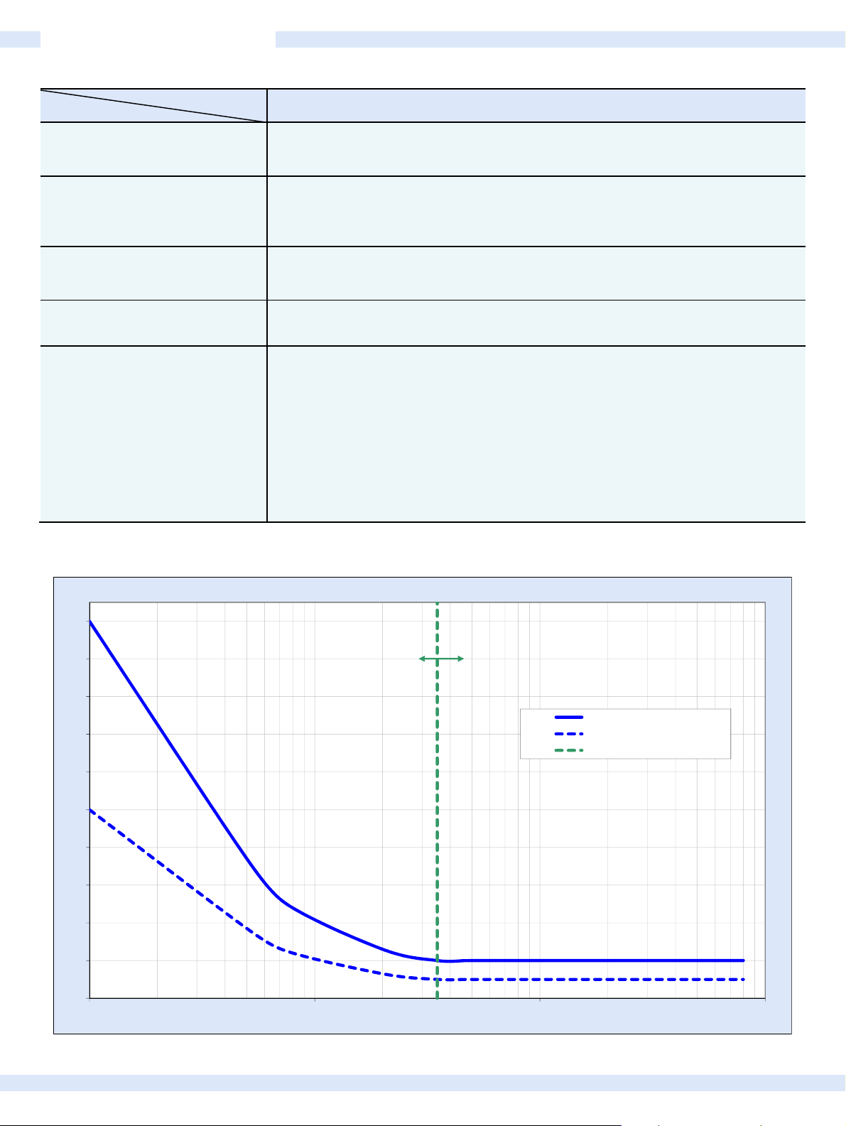
Accuracy of Reading
Note: Repeatability < Accuracy/2
see Figure 4
Wetted Surface Area [cm2] 29.5 32.2 53.2 173.5
Wetted Surface Area [ml] 4 4.8 12.3 95.8
Weight [g] 42 43 61 125
Pressure Drop Coefficient C at 20°C
P = C x Q2 ,
16.8 0.88 0.075 0.0035
Q = Flow [lpm], P = Press. Drop [kPa]
Fluid Temperature Normal range: 10 – 60 °C ( 50 – 140 °F )
Ambient Temperature 0 – 40 °C (32 – 104 °F)
Maximum Fluid Pressure 0 – 0.5 MPa ( 0 – 5 bar, 0 – 72.5 psi)
Kinematic Viscosity 0.8 – 40 mm2/s (0.8 – 40 cSt)
Sound Speed 1000 – 2200 m/s
Wet Materials Polypropylene (FDA, USP VI, ADI free), Gamma robust for up to 40 kGy
Sensor Enclosure Classification IP-65 (for connected sensor)
Cable Jacket Material PVC
Cable Length Various extension cables available.
Electrical Connectors Circular type (IP-67), lock-release mounting
LFS-06SU
LFS-06SU-SC1
LFS-06SU:
> 1.7 l/min: ±1%
< 1.7 l/min: ±17 ml/min
LFS-06SU-SC1:
> 0.08 l/min: ±1%
< 0.08 l/min: 0.8 ml/min
LFS-10SU LFS-20SU
> 4.7 l/min: ±1%
< 4.7 l/min: ±47 ml/min
>18.8 l/min: ±1 %
<18.8 l/min: ±188 ml/min
10%
9%
8%
7%
6%
5%
4%
3%
2%
Table 1: Specifications of flow sensors (all data based on calibration with water at 20°C)
Full Scale = 35 mlpm
Full Scale = 800 mlpm
Accuracy of Reading
Repeatability of Reading
Full Scale Change Line
1%
0%
1101001000
[mlpm]
Figure 4: Accuracy and repeatability for single-use sensor LFS-03SU

A
SENSOR SPECIFICATIONS
Triclamp 3/8“
SME BPE 2009
Figure 5: Dimensions for LFS-03SU-Z and LFS-06SU-Z flow sensors
Sensor
Type
LFS-10SU-Z 1/2" 80 138 Ø 12.7 (= 1/2”) Ø 25 Ø 9.4 44.4 18.6 24 110
LFS-20SU-Z 1” 161.2 231.2 Ø 25.4 (= 1”) Ø 50.5 Ø 22.2 82.5 28 34 160
Triclamp
Fitting Size
(ASME BPE 2009)
Dimensions in [mm]
a b c D d e f g L
Figure 6: Dimensions for LFS-10SU-Z and LFS-20SU-Z flow sensors
C
-1C
-PC
l
CONVERTER AND CABLE SPECIFICATIONS
Characteristics Description or Values
Power Supply
Current / Inrush (Start-Up) Current
Ambient Temp
Humidity Range
Enclosure Classification and Material IP-20 (indoor use), ABS
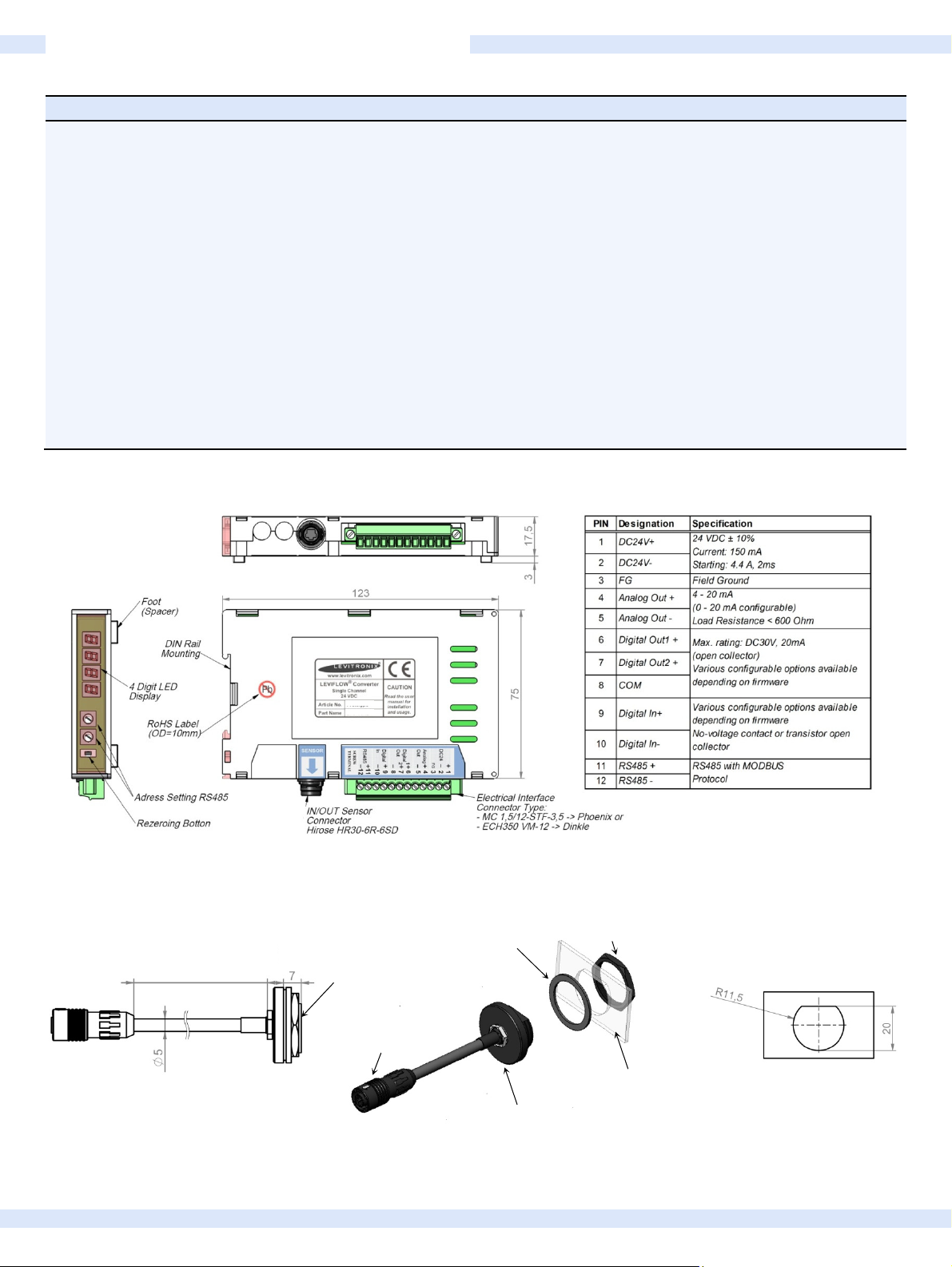
Interfaces
(See Figure 7 for detailed PIN designation and electrical specification)
Configuration Parameters
(Available and configurable with RS485/USB converter and configuration software)
Weight 130 g
Dimensions 123 x 75 x 17.5 mm (see Figure 7 for details)
Mounting DIN rail
Table 2: Specification of converter LFC-1C-PC
24 VDC ± 10%
150 mA / Peak of 3.8 A within 210 μs
0 – 40 °C (32 – 104 °F)
30 - 85% R.H. (no condensation)
- RS485 -> MODBUS protocol -> max. array of 99 channels
- 1x Analog Output 4 – 20mA (0 – 20mA configurable)
- 2x Digital Outputs: Flow Alarm, Measurement Error, Volume Counter Pulse, Volume Counter
Alarm, Flow as Frequency or Bubble Detection (default: normally open)
- 1x Digital Input: Volume Counter Reset or Zero Adjust
- 4 Digit display (flow rate, error codes), re-zero button
- Address potentiometers for RS485 address setting
Viscosity, Low Cutoff, Dampening constant (filter)
Full scale setting, Linearization (15 points), Alarm Outputs (High and Low Alarm)
Volume Counter Settings
100-30374
LF
Figure 7: Dimensions and layout of interfaces of single channel converter LFC-1C-PC
Hex-Nut
Length = 1,3,6 m
Delivered with protective
dust cap on connector)
Sealing Gasket
M22 x 1mm
Mounting Panel Dimensions
Converter
Connector
Mounting Wall
Wall-mountable Adaptor
Figure 8: Dimensions of wall mountable extension cables LFE-C.2

ORDER INFORMATION
1b
1a
Pos. Part Name Article #
LFS-03SU-Z
1a
LFS-03SU-Z-G25 1
LFS-06SU-Z
LFS-06SU-Z-G25
1b
LFS-06SU-Z-SC1
LFS-06SU-Z-SC1-G25 1
LFS-10SU-Z
1c
LFS-10SU-Z-G25 1
LFS-20SU-Z
1d
LFS-20SU-Z-G25 1
1
100-30375
100-30399
100-30377
100-30400
100-30394
100-30406
100-30397
100-30405
100-30379
100-30404
1c
4a
1d
5a
Figure 9: LEVIFLOW® flowmeter components
1% Accuracy
Flow Range
35 – 800 mlpm
1.7 – 8 l/min
0.08 – 8 l/min
4.7 – 20 l/min Triclamp 1/2”
18.8 – 80 l/min Triclamp 1”
Fitting Connector Note
Triclamp 3/8”
5b
Circular Hirose
type with IP67.
4b
5c
2b
2a
--
Table 3: Standard flow sensor configurations
Note 1: Gamma irradiated with dosage > 25 kGy.
Pos. Part Name Part # Description Interfaces
2
LFC-1C-PC 100-30374 Single Channel Converter
(a+b)
Analog Output (4 – 20 mA), 2x Digital Output, 1x Digital Input,
RS485 (MODBUS) protocol
Note: EMI ferrite (2b) for flow sensor cable included in converter package.
3 LFC-1C-PC-SK 100-91072 Converter Starter Kit Includes converter, AC/DC supply, plug-and-play cabling, configuration software.
Table 4: LEVIFLOW® converter
Pos. Part Name Part # Features Special Feature / Description
LFI-C.1-10
4a
LFI-C.1-30
LFI-C.1-60
LFE-C.2-10
4b
LFE-C.2-30
LFE-C.2-60
YN-485I-TR, USB to RS485
5
Adaptor-TR Isolated
190-10307
190-10308
190-10309
190-10310
190-10311
190-10312
100-30392
Cable length: 1 m, PVC
Cable length: 3 m, PVC
Cable length: 6 m, PVC
Cable length: 1 m, PVC
Cable length: 3 m, PVC
Cable length: 6 m, PVC
Structure/Design
Purpose
Interconnect cable for connection between sensor and converter.
Extension cable with wall-mountable connector for cabinet mounting.
Delivered with protective dust cap on wall-mountable connector side.
USB connector (5a) with termination resistor and cable with connector pair (5b and
5c) for external RS485 wire connection. Magnetically isolated. Cable length is 2m.
Communication over fieldbus of converter with PC
Table 5: Accessories

Free Notes Page

T
LEVITRONIX® THE COMPANY
Levitronix
bearingless motor technology to the Semiconductor, Medical and Life Science markets. The company is ISO 9001 certified. Production
and quality control facilities are located in Switzerland. In addition, Levitronix
LEVIFLOW
is the world-wide leader in magnetically levitated bearingless motor technology. Levitronix was the first company to introduce
®
flowmeter series to the market.
is committed to bring other highly innovative products like the
Headquarter and
European Contact
Levitronix GmbH
Technoparkstr. 1
CH-8005 Zurich
Switzerland
Phone: +41 44 445 19 13
Fax: +41 44 445 19 14
E-Mail: salesEurope@levitronix.com
US Contact Japan Contact
Levitronix Technologies LLC
20 Speen Street, Suite 102
Framingham, Massachusetts 01701
USA
Phone: +1 508 861 3800
Fax: +1 508 861 3837
E-Mail: salesUS@levitronix.com
Levitronix Japan K.K.
Wing Eight 5floor, 4-16-4
Asakusabashi, Taito-ku
Tokyo, 111-0053 Japan
Phone: +81 3 5823 4193
Fax: +81 3 5823 4195
E-Mail: salesJapan@levitronix.com
aiwan Contact
Levitronix Taiwan
5F, No. 251, Dong Sec. 1, Guangming
6th Rd., Chu Pei City,
Hsin-Chu 302, Taiwan, R.O.C.
Phone: +886 3 657 6209
Fax: +886 988 321472
E-Mail: salesAsia@levitronix.com
First Release: 18-Jul-14 Last Update: 28-Dec-16 PL-4508-00, Rev02, DCO# 16-181
 Loading...