

Page 1
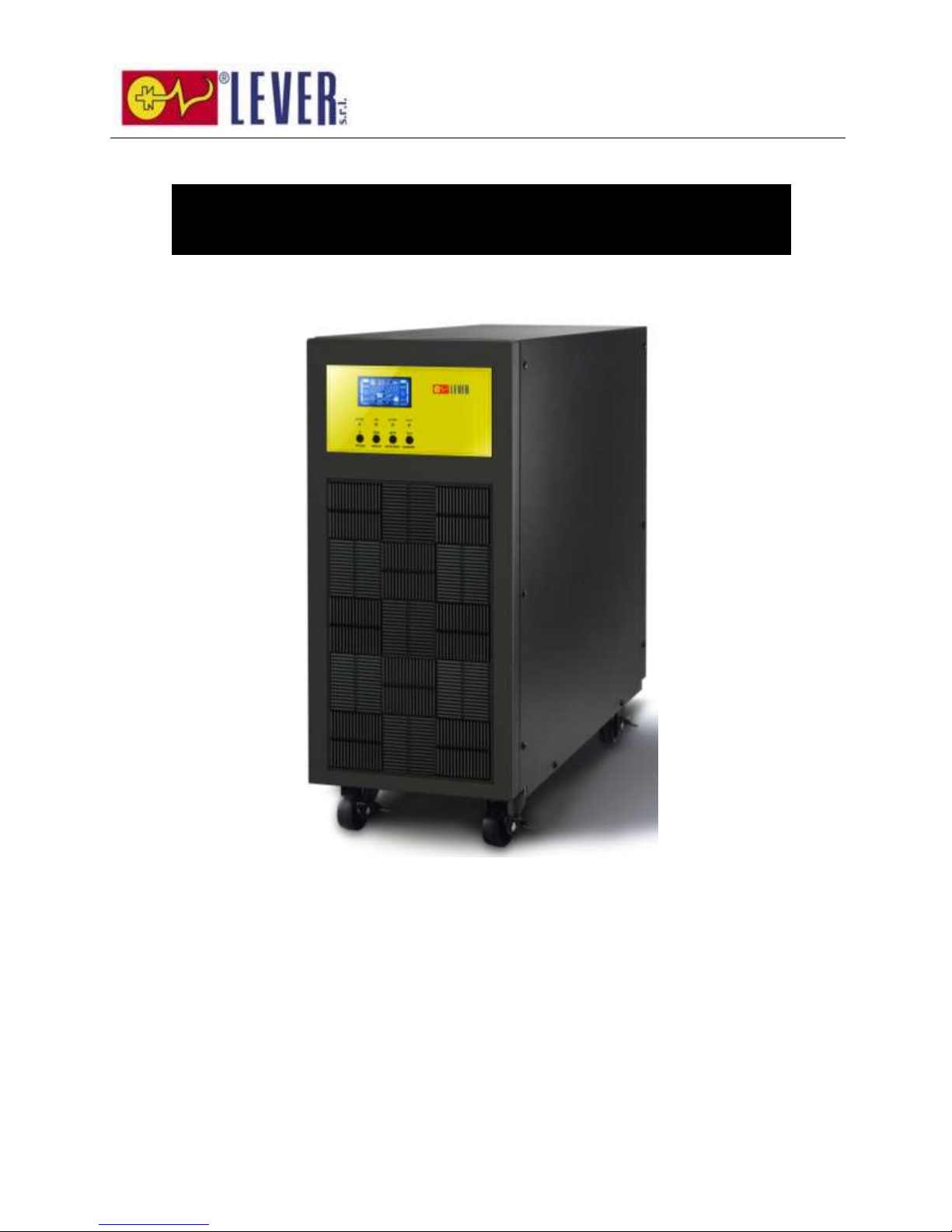
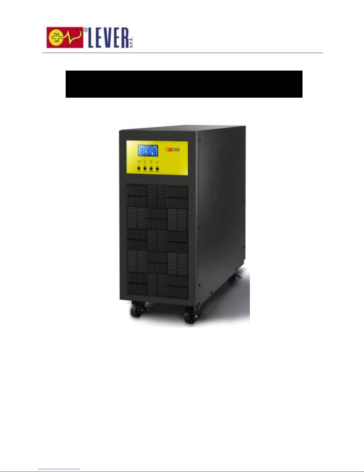
EC1000 Series
6K/10K Online UPS
Uninterruptible Power Supply System
User Manual
Page 2

1
Please comply with all warnings and operating
instructions in this manual strictly. Save this
manual properly and read carefully the following
instructions before installing the unit. Do not
operate this unit before reading through all
safety information and operating instructions
carefully.
Page 3

2
Table of Contents
1. SAFETY AND EMC INSTRUCTIONS ................................................................................................. 3
1-1. TRANSPORTATION AND STORAGE ............................................................................................................... 3
1-2. PREPARATION ....................................................................................................................................... 3
1-3. INSTALLATION ...................................................................................................................................... 3
1-4. OPERATION ......................................................................................................................................... 4
1-5. STANDARDS ......................................................................................................................................... 4
2. INSTALLATION AND OPERATION .................................................................................................. 5
2-1. UNPACKING AND INSPECTION ................................................................................................................... 5
2-2. REAR PANEL VIEW................................................................................................................................. 5
2-3. SINGLE UPS INSTALLATION ..................................................................................................................... 6
2-4. UPS INSTALLATION FOR PARALLEL SYSTEM .................................................................................................. 8
2-5. SOFTWARE INSTALLATION ....................................................................................................................... 9
3. OPERATIONS .................................................................................................................................. 9
3-1. BUTTON OPERATION .............................................................................................................................. 9
3-2. LED INDICATORS AND LCD PANEL .......................................................................................................... 10
3-3. AUDIBLE ALARM.................................................................................................................................. 13
3-4. SINGLE UPS OPERATION ...................................................................................................................... 13
3-5. PARALLEL OPERATION .......................................................................................................................... 16
3-6. ABBREVIATION MEANING IN LCD DISPLAY ................................................................................................. 18
3-7. LCD SETTING .................................................................................................................................... 18
3-8. OPERATING MODE/STATUS DESCRIPTION ................................................................................................. 24
3-9. FAULT CODE ...................................................................................................................................... 25
3-10. WARNING INDICATOR ........................................................................................................................ 26
4. TROUBLE SHOOTING ................................................................................................................... 26
5. STORAGE AND MAINTENANCE ..................................................................................................... 28
5-1. STORAGE .......................................................................................................................................... 28
5-2. MAINTENANCE .................................................................................................................................... 28
6. SPECIFICATIONS ......................................................................................................................... 30
Page 4
3
1. Safety and EMC instructions
Please read carefully the following user manual and the safety instructions before installing the unit or using
the unit!
1-1. Transportation and Storage
Please transport the UPS system only in the original package to protect against shock and
impact.
The UPS must be stored in the room where it is ventilated and dry.
1-2. Preparation
Condensation may occur if the UPS system is moved directly from cold to warm environment.
The UPS system must be absolutely dry before being installed. Please allow at least two hours for the
UPS system to acclimate the environment.
Do not install the UPS system near water or in moist environments.
Do not install the UPS system where it would be exposed to direct sunlight or nearby heater.
Do not block ventilation holes in the UPS housing.
1-3. Installation
Do not connect appliances or devices which would overload the UPS (e.g. big motor-type
equipment)) to the UPS output sockets or terminal.
Place cables in such a way that no one can step on or trip over them.
Do not block air vents in the housing of UPS. The UPS must be installed in a location with good
ventilation. Ensure enough space on each side for ventilation.
UPS has provided earthed terminal, in the final installed system configuration, equipotential
earth bonding to the external UPS battery cabinets.
The UPS can be installed only by qualified maintenance personnel.
An appropriate disconnect device as short-circuit backup protection should be provided in the
building wiring installation.
An integral single emergency switching device which prevents further supply to the load by the
UPS in any mode of operation should be provided in the building wiring installation.
Connect the earth before connecting to the building wiring terminal.
Installation and Wiring must be performed in accordance with the local electrical laws and
regulations.
Page 5
4
1-4. Operation
Do not disconnect the earth conductor cable on the UPS or the building wiring terminals in any
time since this would cancel the protective earth of the UPS system and of all connected loads.
The UPS system features its own, internal current source (batteries). The UPS output sockets or
output terminal blocks may be electrically live even if the UPS system is not connected to the building
wiring outlet.
In order to fully disconnect the UPS system, first press the “OFF” button and then disconnect the
mains.
Ensure that no liquid or other foreign objects can enter into the UPS system.
The UPS can be operated by any individuals with no previous experience.
1-5. Standards
* Safety
IEC/EN 62040-1
* EMI
Conducted Emission...............................:IEC/EN 62040-2
Category C3
Radiated Emission..................................:IEC/EN 62040-2
Category C3
*EMS
ESD.........................................................:IEC/EN 61000-4-2
Level 4
RS........................................................ ...:IEC/EN 61000-4-3
Level 3
EFT......................................................... :IEC/EN 61000-4-4
Level 4
SURGE................................................... :IEC/EN 61000-4-5
Level 4
CS........................................................... :IEC/EN 61000-4-6
Level 3
Power-frequency Magnetic field.............. :IEC/EN 61000-4-8
Level 4
Low Frequency Signals............................:IEC/EN 61000-2-2
Warning: This is a product for commercial and industrial application in the
second environment-installation restrictions or additional measures may be
needed to prevent disturbances.
Page 6
5
2. Installation and Operation
There are two different types of online UPS: standard and long-run models. Please refer to the following
model table.
Model
Type
Model
Type
6K
Standard
model
6K-SC
Long-run
model
10K
10K-SC
Parallel function is also available for these two types and related installation and operation of Parallel
function will be described in detail in the following content.
2-1. Unpacking and Inspection
Unpack the package and check the package contents. The shipping package contains:
● One UPS
● One user manual
● One monitoring software CD
● One RS-232 cable (option)
● One USB cable
● One parallel cable (only available for parallel model)
● One share current cable (only available for parallel model)
● One battery cable (option)
NOTE: Before installation, please inspect the unit. Be sure that nothing inside the package is damaged
during transportation. Do not turn on the unit and notify the carrier and dealer immediately if there is any
damage or lacking of some parts. Please keep the original package in a safe place for future use.
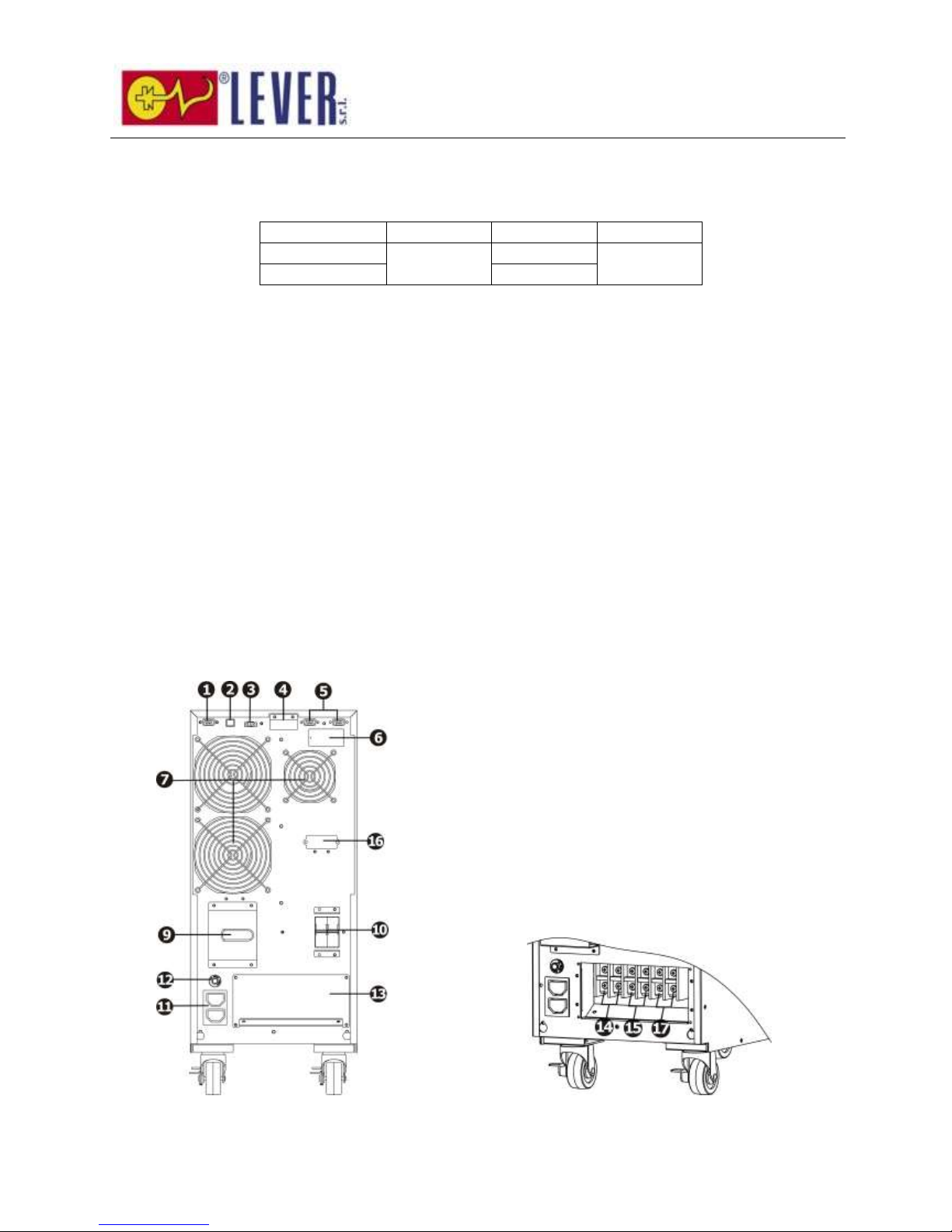
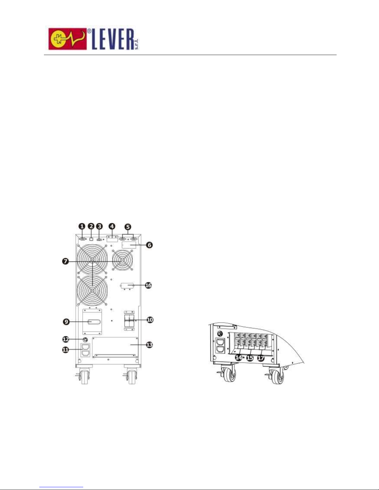
2-2. Rear Panel View
Diagram 1: 6k(SC)/10k(SC) Rear Panel Diagram 2: 6k(SC)/10k(SC) Input/Output
Terminal
Page 7
6
1. RS-232 communication port
2. USB communication port
3. Emergency power off function connector (EPO connector)
4. Share current port (only available for parallel model)
5. Parallel port (only available for parallel model)
6. Intelligent slot
7. Cooling fan
8. External maintenance bypass switch port
9. Maintenance bypass switch
10. Input circuit breaker
11. Output receptacles: connect to mission-critical loads
12. Output circuit breaker for receptacles
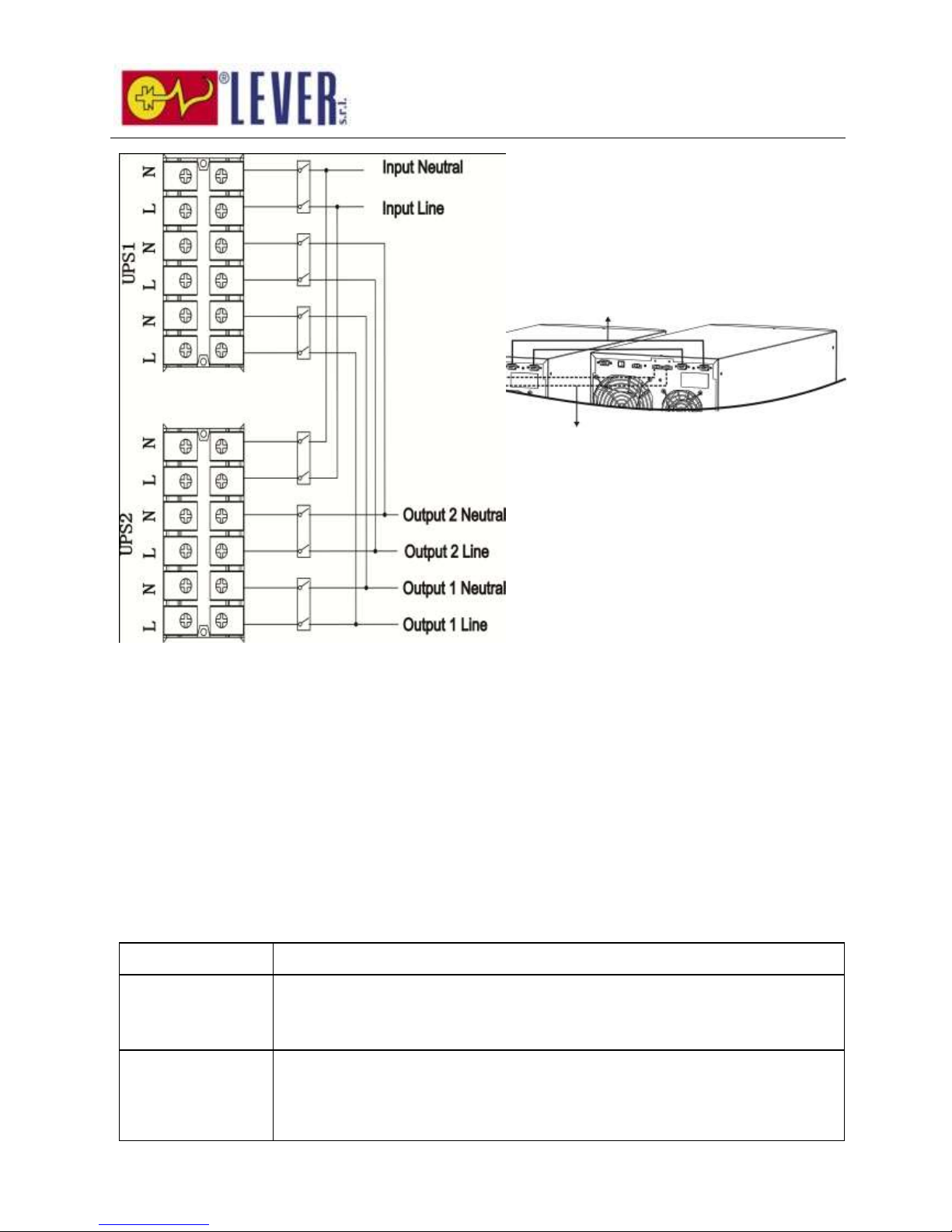
13. Input/Output terminal (Refer to Diagram 2, 4, 6 for the details)
14. Output terminal: connect to mission-critical loads
15. Programmable output terminal: connect to non-critical loads
16. External battery connector
17. Utility input terminal
2-3. Single UPS Installation
Installation and wiring must be performed in accordance with the local electric laws/regulations and execute
the following instructions by professional personnel.
1) Make sure the mains wire and breakers in the building are enough for the rated capacity of UPS to
avoid the hazards of electric shock or fire.
NOTE: Do not use the wall receptacle as the input power source for the UPS, as its rated current is less than
the UPS’s maximum input current. Otherwise the receptacle may be burned and destroyed.
2) Switch off the mains switch in the building before installation.
3) Turn off all the connected devices before connecting to the UPS.
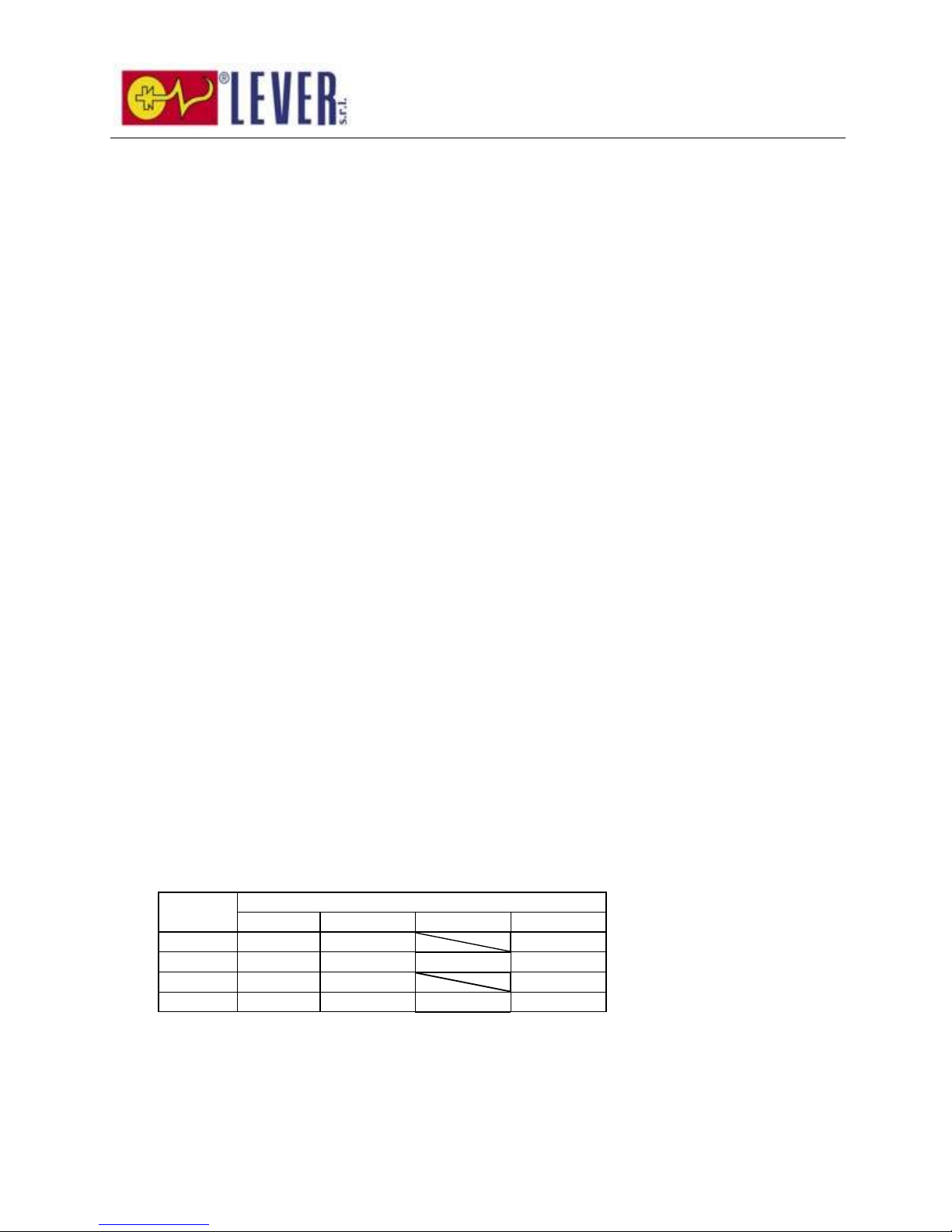
4) Prepare wires based on the following table:
Model
Wiring spec (mm2)
Input
Output
Battery
Ground
6k
10
10 10
6kL
10
10
10
10
10k
16
16 16
10kL
16
16
16
16
NOTE 1: The cable for 6k/6kL should be able to withstand over 40A current. It is recommended to use
10 mm2 or thicker wire for safety and efficiency.
NOTE 2: The cable for 10k/10kL should be able to withstand over 63A current. It is recommended to
use 16mm2or thicker wire for safety and efficiency.
NOTE 3: The selections for color of wires should be followed by the local electrical laws and
Page 8
7
regulations.
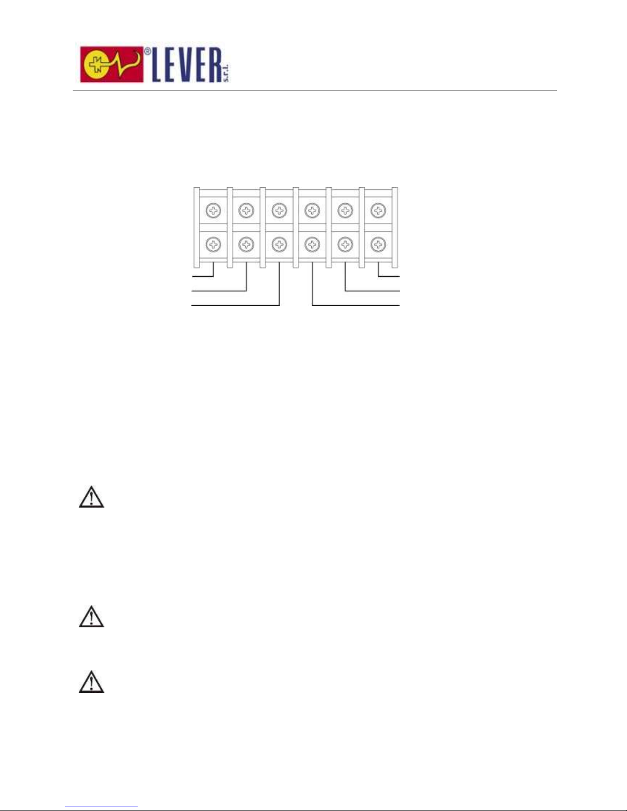
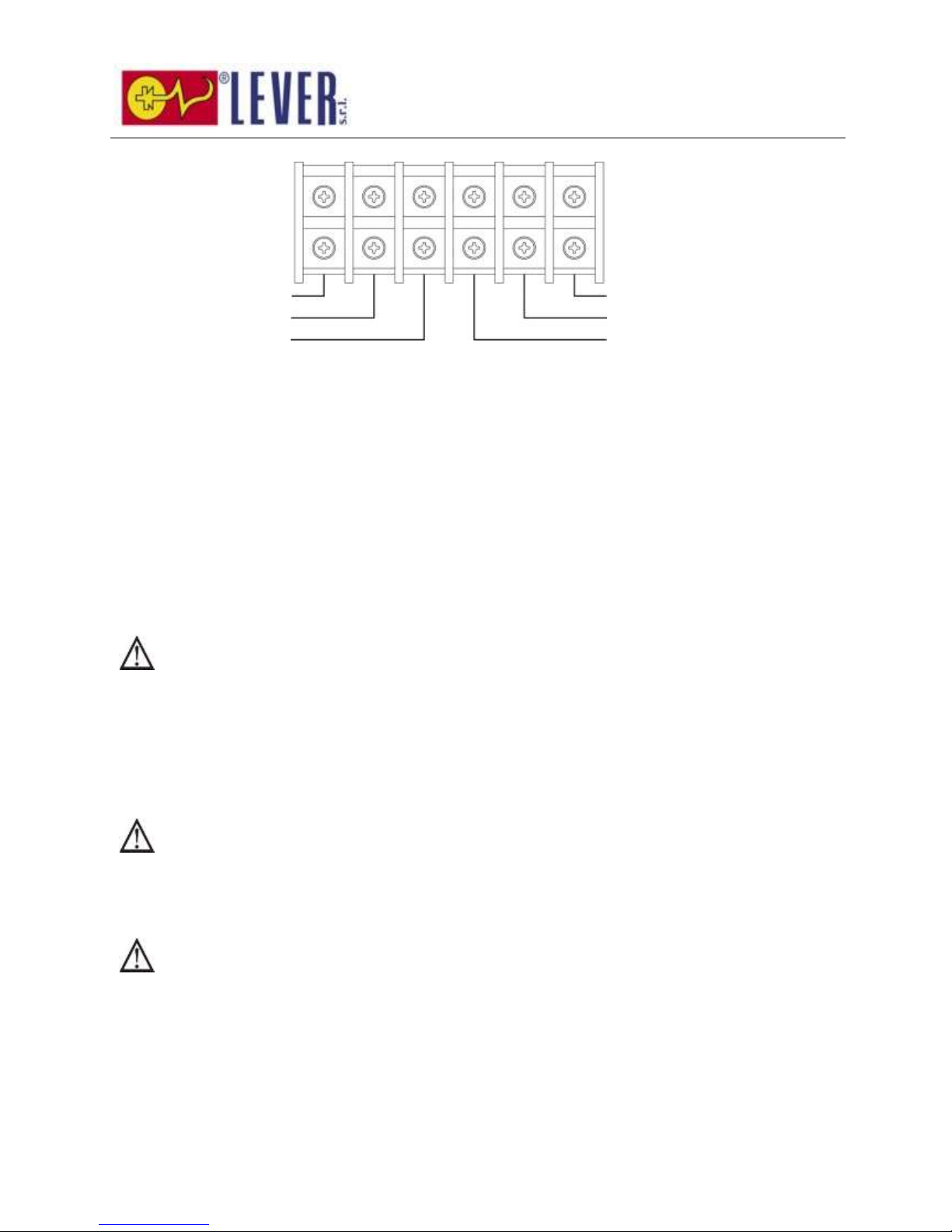
5) Remove the terminal block cover on the rear panel of UPS. Then connect the wires according to the
following terminal block diagrams: (Connect the earth wire first when making wire connection. Disconnect
the earth wire last when making wire disconnection!)
Terminal Block wiring diagram
NOTE 1: Make sure that the wires are connected tightly with the terminals.
NOTE 2: There are two kinds of outputs: output terminal/outlets and programmable terminal. Please
connect non-critical devices to the programmable terminal and critical devices to the output terminal/outlets.
During power failure, you may extend the backup time to critical devices by setting shorter backup time for
non-critical devices.
NOTE 3: Please install the output breaker between the output terminal and the load, and the breaker
should be qualified with leakage current protective function if necessary.
6) Put the terminal block cover back to the rear panel of the UPS.
Warning: (Only for standard model)
● Make sure the UPS is not turned on before installation. The UPS should not be turned on during wiring
connection.
● Do not try to modify the standard model to the long-run model. Particularly, do not try to connect the
standard internal battery to the external battery. The battery type and voltage may be different. If you
connect them together, it maybe causes the hazard of electric shock or fire!
Warning: (Only for long-run model)
● Make sure a DC breaker or other protection device between UPS and external battery pack is installed. If
not, please install it carefully. Switch off the battery breaker before installation.
Warning:
● For standard battery pack, there are one DC breaker to disconnect the battery pack and the UPS. But for
other external battery pack, make sure a DC breaker or other protection device between UPS and
external battery pack is installed. If not, please install it carefully. Switch off the battery breaker before
installation.
Input Neutral
Input Line
Output 2 Neutral
Output 2 Line
Output 1 Neutral
Output 1 Line
Page 9

8
NOTE: Set the battery pack breaker in “OFF” position and then install the battery pack.
● Pay highly attention to the rated battery voltage marked on the rear panel. If you want to change the
numbers of the battery pack, please make sure you modify the setting simultaneously. The connection
with wrong battery voltage may cause permanent damage of the UPS. Make sure the voltage of the
battery pack is correct.
● Pay highly attention to the polarity marking on external battery terminal block, and make sure the
correct battery polarity is connected. Wrong connection may cause permanent damage of the UPS.
● Make sure the protective earth ground wiring is correct. The wire current spec, color, position,
connection and conductance reliability should be checked carefully.
● Make sure the utility input & output wiring is correct. The wire current spec, color, position, connection
and conductance reliability should be checked carefully. Make sure the L/N site is correct, not reverse
and short-circuited.
2-4. UPS Installation for Parallel System
If the UPS is only available for single operation, you may skip this section to the next.
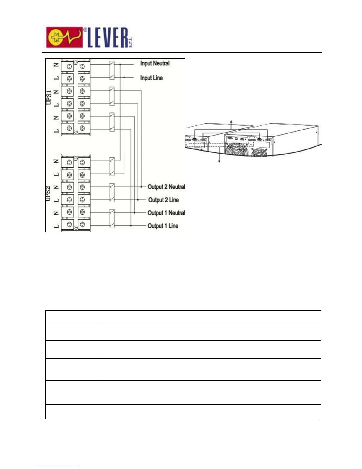
1) Install and wires the UPSs according to the section 2-3.
2) Connect the output wires of each UPS to an output breaker.
3) Connect all output breakers to a major output breaker. Then this major output breaker will directly
connect to the loads.
4) Each UPS is connected to an independent battery pack.
5) Remove the cover of parallel share current cable port on the UPS, connect each UPS one by one with the
parallel cable and share current cable, and then screw the cover back again.
NOTE: The parallel system can not use one battery pack. Otherwise, it will cause system permanent failure.
6) Refer to the following wiring diagram:
Page 10
9
Diagram 1: Power cable connection
2-5. Software Installation
For optimal computer system protection, install UPS monitoring software to fully configure UPS shutdown.
3. Operations
3-1. Button Operation
Button
Function
ON/Enter Button
Turn on the UPS: Press and hold the button more than 0.5s to turn on the UPS.
Enter Key: Press this button to confirm the selection in setting menu.
OFF/ESC Button
Turn off the UPS: Press and hold the button more than 0.5s to turn off the UPS.
Esc key: Press this button to return to last menu in setting menu.
Test/Up Button
Battery test: Press and hold the button more than 0.5s to test the battery while
in AC mode, or CVCF mode.
UP key: Press this button to display next selection in setting menu.
Mute/Down Button
Mute the alarm: Press and hold the button more than 0.5s to mute the buzzer.
Please refer to section 3-4-9 for details.
Down key: Press this button to display previous selection in setting menu.
Test/Up +
Mute/Down Button
Press and hold the two buttons simultaneous more than 1s to enter/escape the
setting menu.
* CVCF mode means converter mode.
Diagram 2
Parallel communication port connection
Share current cable connection
Page 11
10
3-2. LED Indicators and LCD Panel
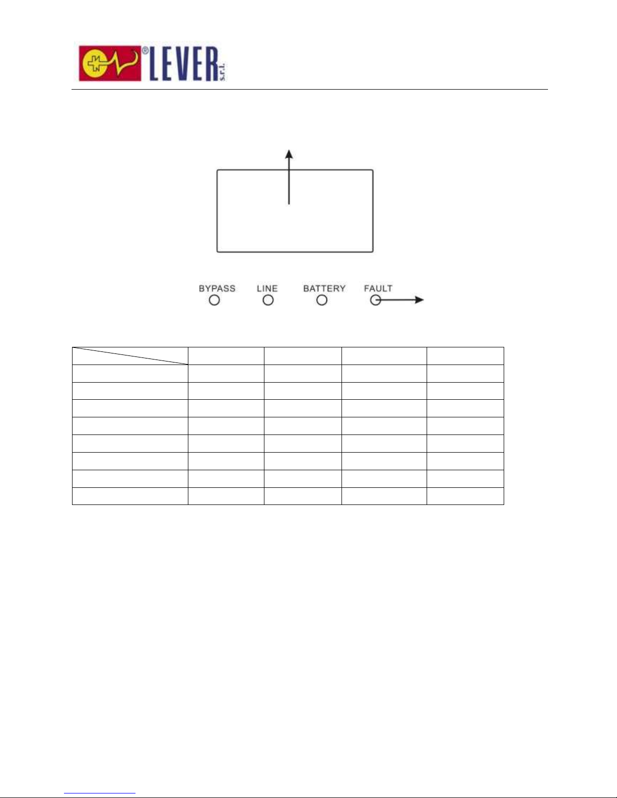
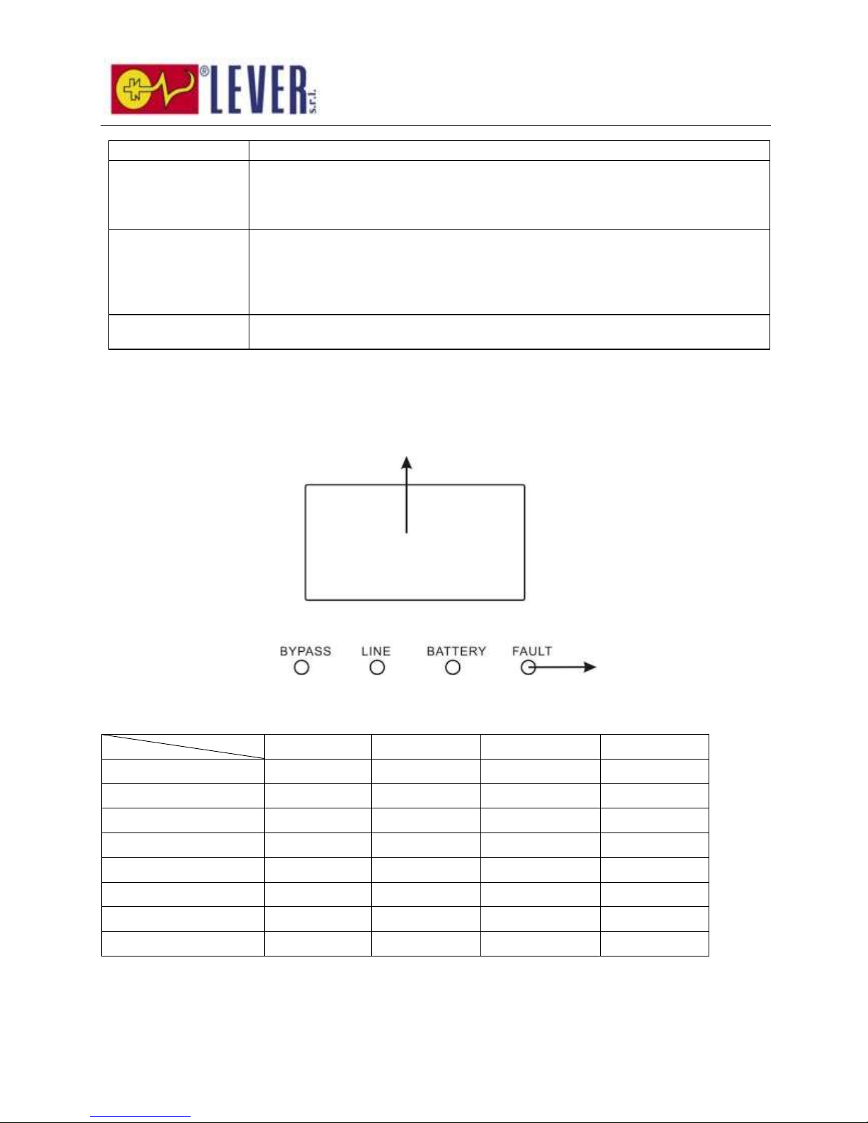
LED Indicators:
There are 4 LEDs on front panel to show the UPS working status:
Mode LED
Bypass
Line
Battery
Fault
UPS Startup
● ● ●
●
Bypass mode
●
○ ○ ○
AC mode
○ ● ○
○
Battery mode
○
○ ● ○
CVCF mode
○ ● ○
○
Battery Test
● ● ●
○
ECO mode
●
●
○
○
Fault
○ ○ ○
●
Note: ● means LED is lighting, and ○ means LED is faded.
LCD panel
LED indicators
Page 12
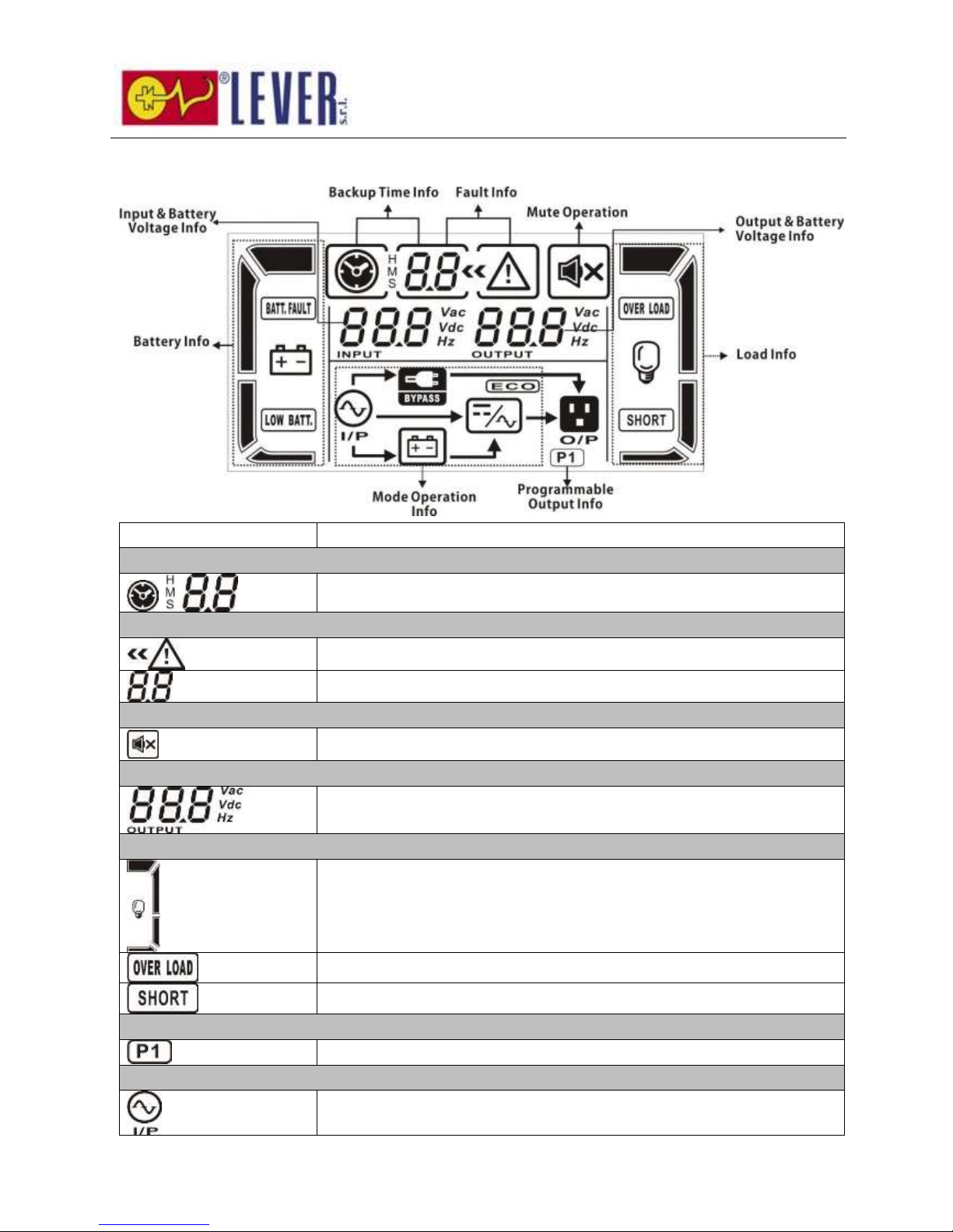
11
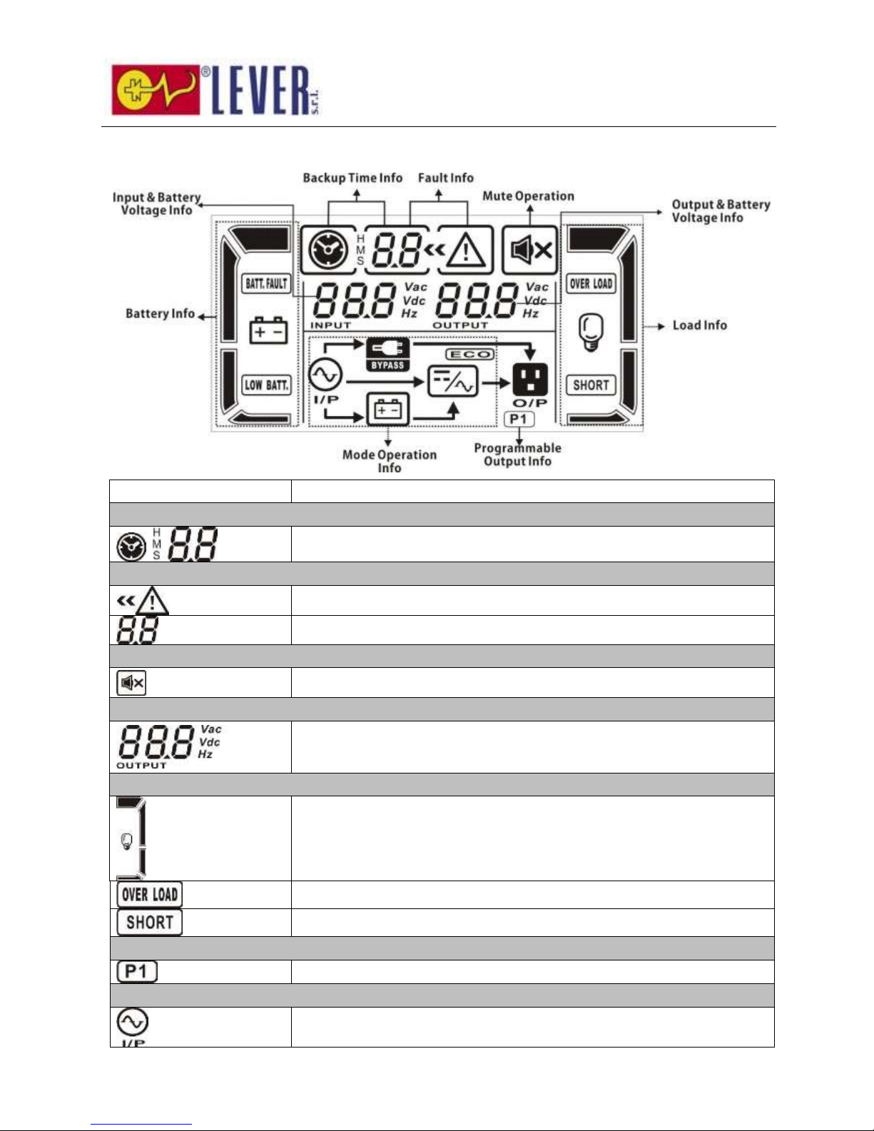
LCD Panel:
Display
Function
Backup time information
Indicates battery discharge time in numbers.
H: hours, M: minutes, S: seconds
Fault information
Indicates that the warning and fault occurs.
Indicates the fault codes, and the codes are listed in details in section 3-9.
Mute operation
Indicates that the UPS alarm is disabled.
Output & Battery voltage information
Indicates the output voltage, frequency or battery voltage.
Vac: output voltage, Vdc: battery voltage, Hz: frequency
Load information
Indicates the load level by 0-25%, 26-50%, 51-75%, and 76-100%.
Indicates overload.
Indicates the load or the output is short.
Programmable output information
Indicates that the programmable outputs are working.
Mode operation information
Indicates the UPS connects to the mains.
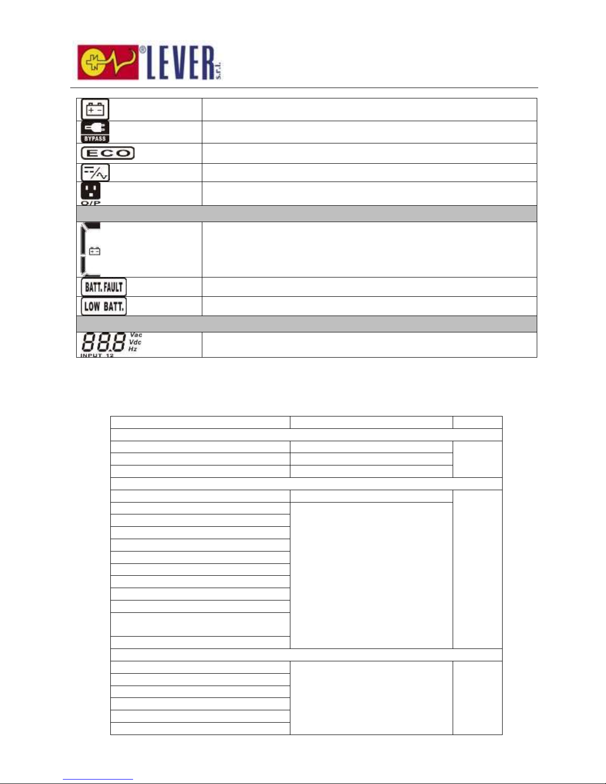
Page 13
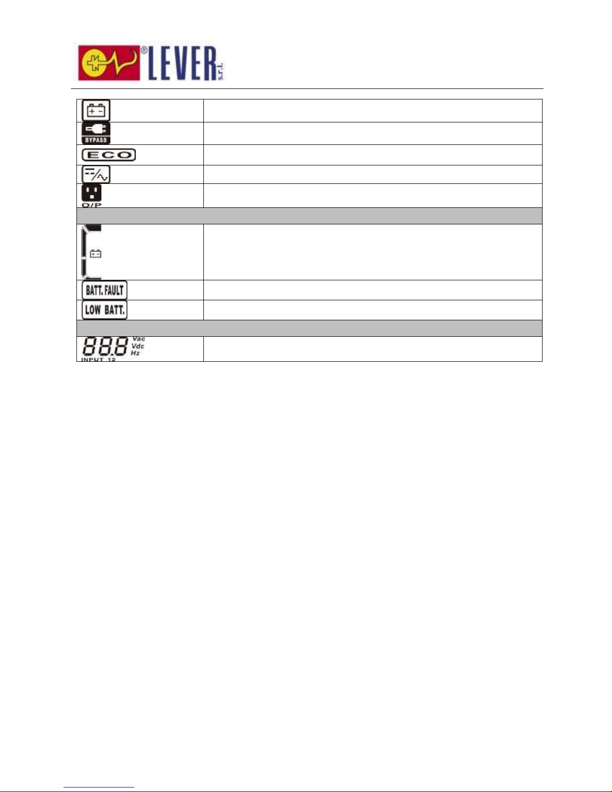
12
Indicates the battery is working.
Indicates the bypass circuit is working.
Indicates the ECO mode is enabled.
Indicates the Inverter circuit is working.
Indicates the output is working.
Battery information
Indicates the Battery capacity by 0-25%, 26-50%, 51-75%, and 76-100%.
Indicates the battery is not connected.
Indicates low battery level and low battery voltage.
Input & Battery voltage information
Indicates the input voltage or frequency or battery voltage.
Vac: Input voltage, Vdc: battery voltage, Hz: input frequency
Page 14

13
3-3. Audible Alarm
Description
Buzzer status
Muted
UPS status
Bypass mode
Beeping once every 2 minutes
Yes
Battery mode
Beeping once every 4 seconds
Fault mode
Beeping continuously
Warning
Overload
Beeping twice every second
No
Low battery
Beeping once every second
Battery unconnected
Over charge
EPO enable
Fan failure/Over temperature
Charger failure
IP fuse broken
Overload 3 times in 30min
EPO status
Cover of maintain switch is open
Parallel protection
Fault
Bus start failure
Beeping continuously
Yes
Bus over
Bus under
Bus unbalance
Inverter soft start failure
High Inverter voltage
Low Inverter voltage
Inverter output short circuited
Negative power fault
Battery SCR short circuited
Inverter relay short circuited
Parallel communication failure
Parallel output current unbalance
Over temperature
CPU communication failure
Overload
3-4. Single UPS Operation
1. Turn on the UPS with utility power supply (in AC mode)
1) After power supply is connected correctly, set the breaker of the battery pack at “ON” position (the
step only available for long-run model). Then set the input breaker at “ON” position. At this time
the fan is running and the UPS supplies power to the loads via the bypass. The UPS is operating in
Bypass mode.
NOTE: When UPS is in Bypass mode, the output voltage will directly power from utility after you
Page 15

14
switch on the input breaker. In Bypass mode, the load is not protected by UPS. To protect your
precious devices, you should turn on the UPS. Refer to next step.
2) Press and hold the “ON” button for 0.5s to turn on the UPS and the buzzer will beep once.
3) A few seconds later, the UPS will enter to AC mode. If the utility power is abnormal, the UPS will
operate in Battery mode without interruption.
NOTE: When the UPS is running out battery, it will shut down automatically at Battery mode. When the
utility power is restored, the UPS will auto restart in AC mode.
2. Turn on the UPS without utility power supply (in Battery mode)
1) Make sure that the breaker of the battery pack is at “ON” position (only for long-run model).
2) Press and hold the “ON” button for 0.5s to turn on the UPS, and the buzzer will beep once.
3) A few seconds later, the UPS will be turned on and enter to Battery mode.
3. Connect devices to UPS
After the UPS is turned on, you can connect devices to the UPS.
1) Turn on the UPS first and then switch on the devices one by one, the LCD panel will display total
load level.
2) If it is necessary to connect the inductive loads such as a printer, the in-rush current should be
calculated carefully to see if it meets the capacity of the UPS, because the power consumption of
this kind of loads is too big.
3) If the UPS is overload, the buzzer will beep twice every second.
4) When the UPS is overload, please remove some loads immediately. It is recommended to have the
total loads connected to the UPS less than 80% of its nominal power capacity to prevent overload
for system safety.
5) If the overload time is over acceptable time listed in spec at AC mode, the UPS will automatically
transfer to Bypass mode. After the overload is removed, it will return to AC mode. If the overload
time is over acceptable time listed in spec at Battery mode, the UPS will become fault status. At this
time, if bypass is enabled, the UPS will power to the load via bypass. If bypass function is disabled
or the input power is not within bypass acceptable range, it will cut off output directly.
4. Charge the batteries
1) After the UPS is connected to the utility power, the charger will charge the batteries automatically
except in Battery mode or during battery self-test.
2) Suggest to charge batteries at least 10 hours before use. Otherwise, the backup time may be
shorter than expected time.
3) Make sure the battery numbers setting on the control board (Please refer to the section 3-4-12 for
detailed setting) is consistent to real connection.
Page 16

15
5. Battery mode operation
1) When the UPS is in Battery mode, the buzzer will beep according to different battery capacity. If the
battery capacity is more than 25%, the buzzer will beep once every 4 seconds; If the battery
voltage drops to the alarm level, the buzzer will beep quickly (once every sec) to remind users that
the battery is at low level and the UPS will shut down automatically soon. Users could switch off
some non-critical loads to disable the shutdown alarm and prolong the backup time (the UPS would
cut off the programmable output terminal automatically when the programmable timer function is
enabled). If there is no more load to be switched off at that time, you have to shut down all loads
as soon as possible to protect the devices or save data. Otherwise, there is a risk of data loss or
load failure.
2) In Battery mode, if buzzer sound annoys, users can press the Mute button to disable the buzzer.
3) The backup time of the long-run model depends on the external battery capacity.
4) The backup time may vary from different environment temperature and load type.
5) When setting backup time for 16.5 hours (default value from LCD panel), after discharging 16.5
hours, UPS will shut down automatically to protect the battery. This battery discharge protection
can be enabled or disabled through LCD panel control. (Refer to 3-7 LCD setting section)
6. Test the batteries
1) If you need to check the battery status when the UPS is running in AC mode/CVCF mode/ECO mode,
you could press the “Test” button to let the UPS do battery self-test.
2) To keep the system reliable, the UPS will perform the battery self-test automatically periodically.
The default setting period is once per week.
3) Users also can set battery self-test through monitoring software.
4) If the UPS is at battery self-test, the LCD display and buzzer indication will be the same as at
Battery mode except that the battery LED is flashing.
7. Turn off the UPS with utility power supply in AC mode
1) Turn off the inverter of the UPS by pressing “OFF” button for at least 0.5s, and then the buzzer will
beep once. The UPS will turn into Bypass mode.
NOTE 1: If the UPS has been set to enable the bypass output, it will bypass voltage from utility
power to output sockets and terminal even though you have turned off the UPS (inverter).
NOTE 2: After turning off the UPS, please be aware that the UPS is working at Bypass mode and
there is risk of power loss for connected devices.
2) In Bypass mode, output voltage of the UPS is still present. In order to cut off the output, switch off
the input breaker. A few seconds later, there is no display shown on the display panel and UPS is
complete off.
8. Turn off the UPS without utility power supply in Battery mode
1) Turn off the UPS by pressing “OFF” button for at least 0.5s, and then the buzzer will beep once.
2) Then UPS will cut off power to output and there is no display shown on the display panel.
Page 17

16
9. Mute the buzzer
1) To mute the buzzer, please press the “Mute” button for at least 0.5s. If you press it again after the
buzzer is muted, the buzzer will beep again.
2) Some warning alarms can’t be muted unless the error is fixed. Please refer to section 3-3 for the
details.
10. Operation in warning status
1) When Fault LED flashes and the buzzer beeps once every second, it means that there are some
problems for UPS operation. Users can get the fault code from LCD panel. Please check the trouble
shooting table in chapter 4 for details.
2) Some warning alarms can’t be muted unless the error is fixed. Please refer to section 3-3 for the
details.
11. Operation in Fault mode
1) When Fault LED illuminates and the buzzer beeps continuously, it means that there is a fatal error in
the UPS. Users can get the fault code from display panel. Please check the trouble shooting table
in chapter 4 for details.
2) Please check the loads, wiring, ventilation, utility, battery and so on after the fault occurs. Don’t try
to turn on the UPS again before solving the problems. If the problems can’t be fixed, please contact
the distributor or service people immediately.
3) For emergency case, please cut off the connection from utility, external battery, and output
immediately to avoid more risk or danger.
12. Operation of changing battery numbers
1) This operation is only available for professional or qualified technicians.
2) Turn off the UPS. If the load couldn’t be cut off, you should remove the cover of maintenance
bypass switch on the rear panel and turn the maintenance switch to “BPS” position first.
3) Switch off the input breaker, and switch off the battery breaker (only available for long-run model).
4) Remove the cabinet, and then modify the jumper on the control board to set the battery numbers
(refer to NOTE below). Then disconnect battery wire for standard model and modify the battery
pack carefully. After complete the changes, put the cabinet back.
NOTE: JP1 setting on the control board: please shorts the Pin5 & Pin6 and Pin7 & Pin8 for 20 pcs
batteries; shorts the Pin5 & Pin6 and keeps Pin7 & Pin8 open for 19 pcs batteries; and keeps every pin
open for 18 pcs batteries.
5) Switch on the input breaker and the UPS will enter Bypass mode. If the UPS is in maintenance
Bypass mode, turn the maintenance switch to “UPS” position and then turn on the UPS.
3-5. Parallel Operation
1. Parallel system connection
1) Make sure all of the UPSs are parallel models, and follow the wiring refer to section 2-4.
2) Turn off the input and output breakers of each UPS, and turn off the battery breaker if the UPS is
Page 18

17
long-run model.
3) Turn on the input breaker of the each UPS and measure the voltage difference between the output
line1 of each UPS with multimeter. If the voltage difference is less than 1V, it means all connections
are correct. If the difference is larger than 1V, check if the wirings are connected correctly.
4) Turn on the input breakers of all UPSs in the parallel systems. Before turning on each UPS in turns,
check if PAR001~PAR003 are displayed in each UPS sequentially. If no “PAR××” exists in any UPS,
please check if the parallel cables are connected correctly.
5) Turn on each UPS in turns and make sure that AC mode LED or Battery mode LED displays in each
UPS. Measure the output voltage of each UPS to check if the voltage difference is less than 2V
(typical 1V) with multimeter. If the difference is more than 2V, please check that parallel cable or
share current cable are connected well. If they are all connected well, maybe it’s UPS internal issue.
Please contact your local distributor or service center for help.
6) Turn off each UPS in turns and after all of them transfer to Bypass mode, turn on the output
breaker of each unit.
7) Turn on the UPSs in the AC mode and then the parallel system connection is complete.
2. Add one new unit into the parallel system
1) You can not add one new unit into the parallel system when whole system is running. You must cut
off the load and shutdown the system.
2) Make sure all of the UPS are the parallel models, and follow the wiring refer to section 2-3.
3) Install the new parallel system refers to the previous section.
3. Remove one unit from the parallel system
There are two methods to remove one unit from the parallel system:
First method:
1) Press the “OFF” key twice and each time should last for more than 0.5s. Then, the UPS will enter
into bypass mode without output.
2) Turn off the output breaker of this unit, and then turn off the input breaker of this unit.
3) After it shuts down, you can turn off the battery breaker (for long-run model) and remove the
parallel cable and share current cable. Then, remove the unit from the parallel system.
Second method:
1) If the bypass is abnormal, you can not remove the UPS without interruption. You must cut off the
load and shut down the system.
2) Make sure the bypass setting is enabled in each UPS and then turn off the running system. All UPSs
will transfer to Bypass mode. Remove all the maintenance bypass covers and set the maintenance
switches from “UPS” to “BPS”. Turn off the input breakers and battery breakers.
3) Remove the UPS that you want.
4) Turn on the input breaker of the remaining UPSs and the system will transfer to Bypass mode.
5) Set the maintenance switches from “BPS” to “UPS and put the maintenance bypass covers back.
Turn on the remaining UPSs and finish the parallel system connection.
Page 19
18
Warning: (Only for the parallel system)
● Before turning on the parallel system to activate inverter, make sure that all unit’s maintenance switch
at the same position.
● When parallel system is turned on to work through inverter, please do not operate the maintenance
switch of any unit.
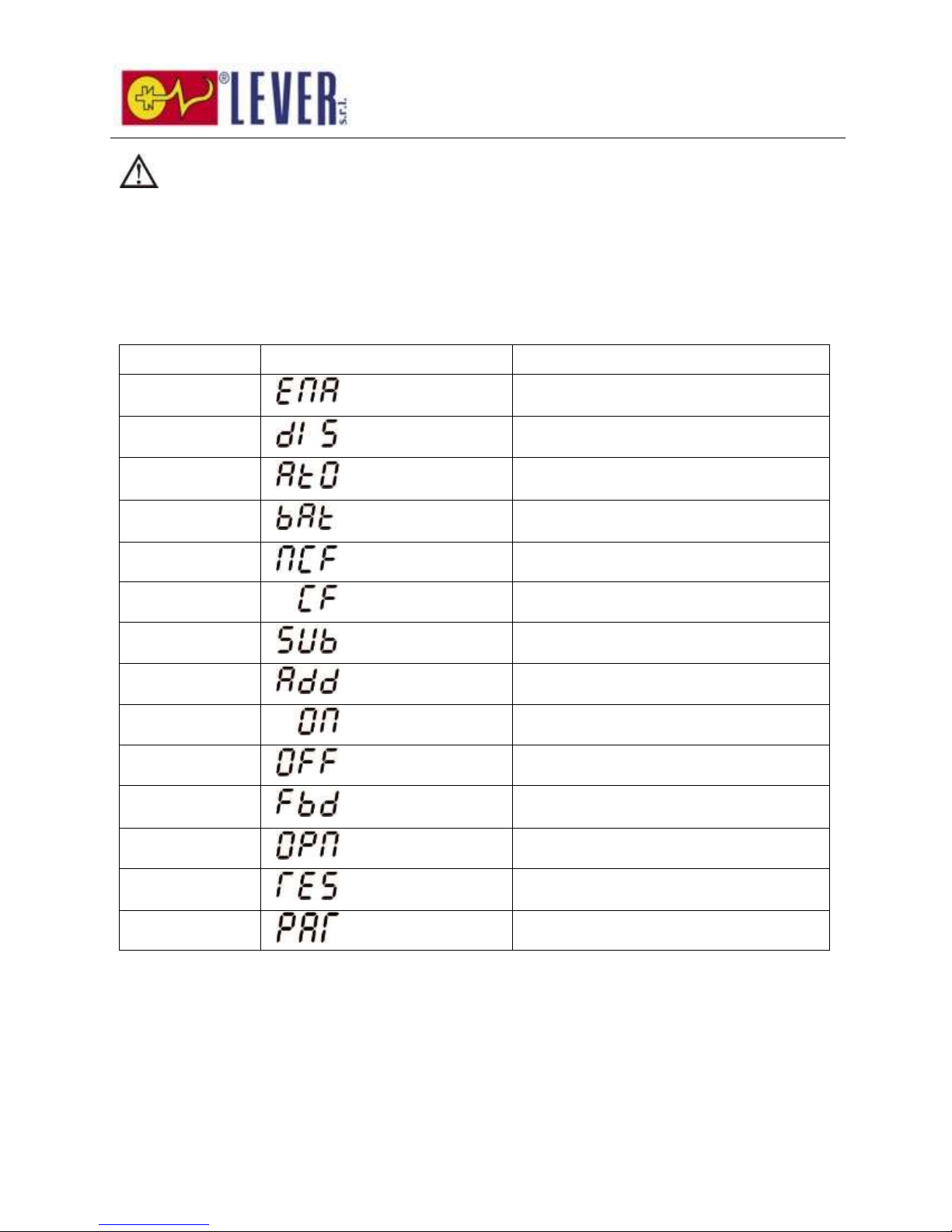
3-6. Abbreviation Meaning in LCD Display
Abbreviation
Display content
Meaning
ENA
Enable
DIS
Disable
ATO
Auto
BAT
Battery
NCF
Normal mode (not CVCF mode)
CF
CVCF mode
SUB
Subtract
ADD
Add
ON
On
OFF
Off
FBD
Not allowed
OPN
Allow
RES
Reserved
PAR
Parallel
3-7. LCD Setting
There are three parameters to set up the UPS. Refer to following diagram.
Page 20
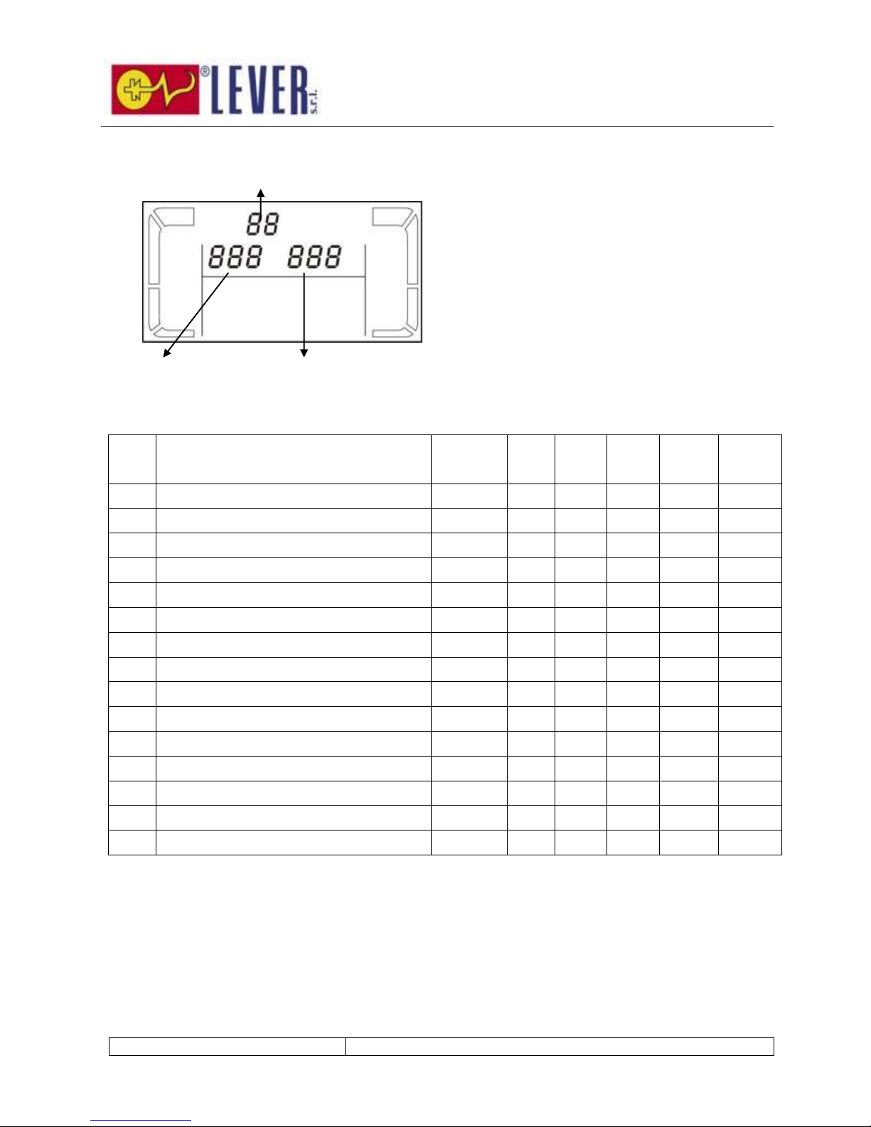
19
Parameter 1: It’s for program alternatives.
There are 15 programs to set up. Refer to below
table.
Parameter 2 and parameter 3 are the setting
options or values for each program.
15 programs available list for parameter 1:
Code
Description
Bypass
AC
ECO
CVCF
Battery
Battery
Test
01
Output voltage
Y
02
Output frequency
Y
03
Voltage range for bypass
Y
04
Frequency range for bypass
Y
05
ECO mode enable/disable
Y
06
Voltage range for ECO mode
Y
07
ECO mode frequency range setting
Y
08
Bypass mode setting
Y
Y
09
Battery backup time setting
Y Y Y Y Y
Y
10
Programmable output setting**
Y Y Y Y Y
Y
11
Shutdown point for programmable output
Y Y Y Y Y
Y
12
Hot standby function enable/disable
Y Y Y Y Y
Y
13
Battery voltage adjustment
Y Y Y Y Y
Y
14
Charger voltage adjustment
Y Y Y Y Y
Y
15
Output voltage adjustment
Y
Y Y
*Y means that this program can be set in this mode.
**Programmable output setting is not supported by Rack models.
Note: All parameter settings will be saved only when UPS shuts down normally with internal or external battery
connection. (Normal UPS shutdown means turning off input breaker in bypass mode).
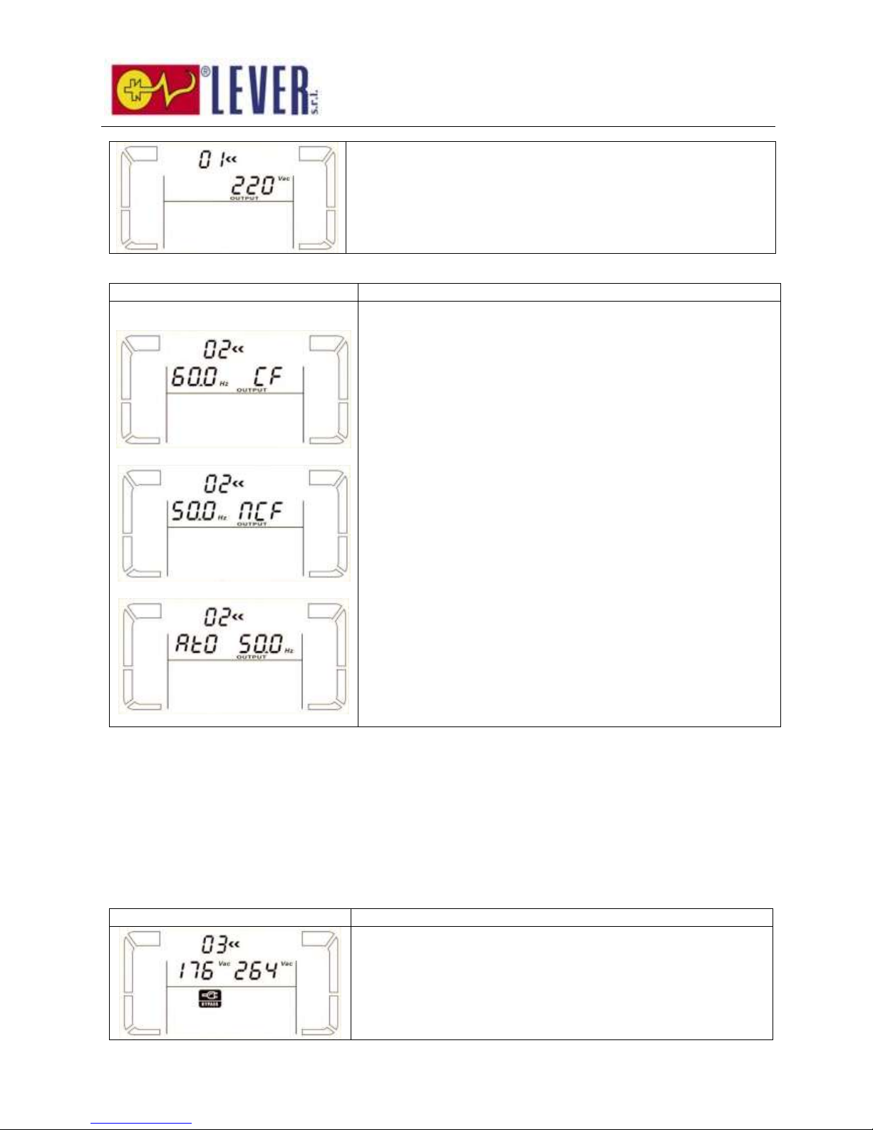
01: Output voltage
Interface
Setting
Parameter 1
Parameter 2
Parameter 3
Page 21
20
Parameter 3: Output voltage
You may choose the following output voltage in parameter 3:
208: Presents output voltage is 208Vac
220: Presents output voltage is 220Vac
230: Presents output voltage is 230Vac
240: Presents output voltage is 240Vac
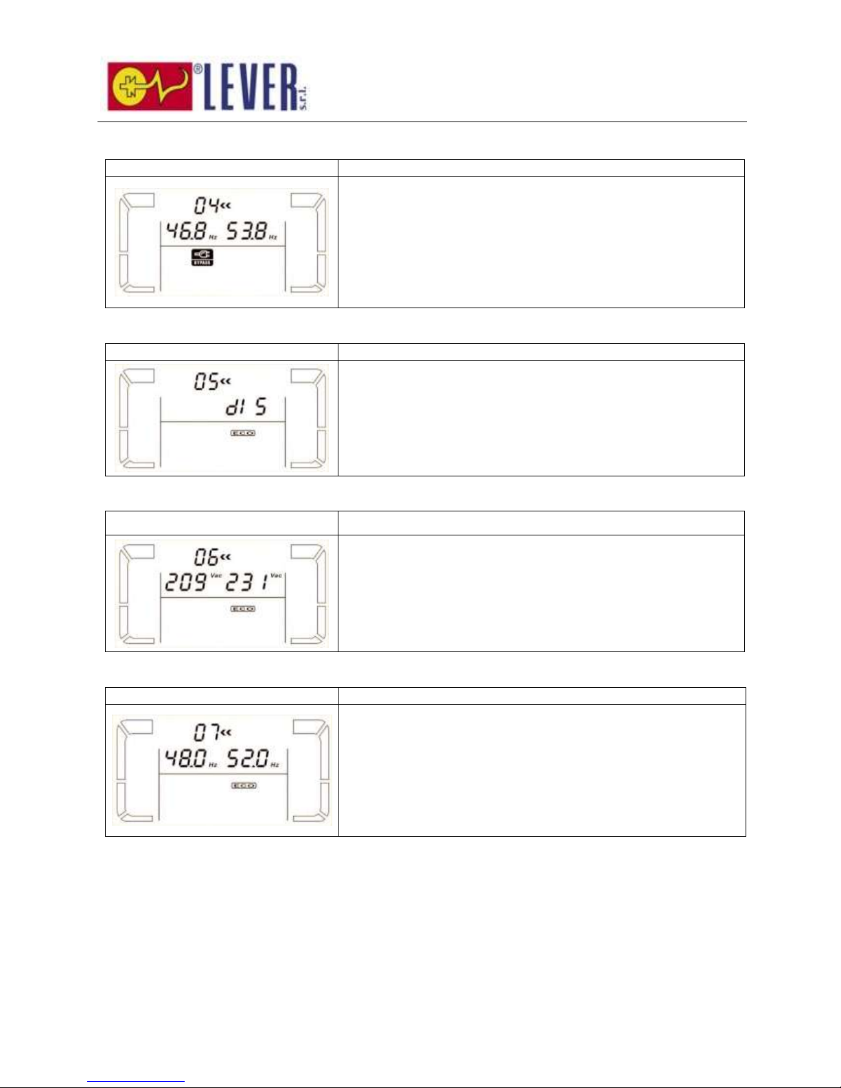
02: Output frequency
Interface
Setting
60 Hz, CVCF mode
50 Hz, Normal mode
ATO
Parameter 2: Output Frequency
Setting the output frequency. You may choose following three
options in parameter 2:
50.0Hz: The output frequency is setting for 50.0Hz.
60.0Hz: The output frequency is setting for 60.0Hz.
ATO: If selected, output frequency will be decided according to
the latest normal utility frequency. If it is from 46Hz to 54Hz, the
output frequency will be 50.0Hz. If it is from 56Hz to 64Hz, the
output frequency will be 60.0Hz. ATO is default setting.
Parameter 3: Frequency mode
Setting output frequency at CVCF mode or not CVCF mode. You
may choose following two options in parameter 3:
CF: Setting UPS to CVCF mode. If selected, the output frequency
will be fixed at 50Hz or 60Hz according to setting in parameter 2.
The input frequency could be from 46Hz to 64Hz.
NCF: Setting UPS to normal mode (not CVCF mode). If selected,
the output frequency will synchronize with the input frequency
within 46~54 Hz at 50Hz or within 56~64 Hz at 60Hz according to
setting in parameter 2. If 50 Hz selected in parameter 2, UPS will
transfer to battery mode when input frequency is not within
46~54 Hz. If 60Hz selected in parameter 2, UPS will transfer to
battery mode when input frequency is not within 56~64 Hz.
*If Parameter 2 is ATO, the Parameter 3 will show the current
frequency.
Note: If the UPS is set to CVCF mode, the bypass function will be disabled automatically.
But when a single UPS without parallel function is powered on with mains and before the UPS
finished the startup, there will be a few seconds of voltage pulse (same as the input voltage)
on the bypass output.
If you need to remove the pulse on this mode to protect your load better, you could contact the
dealer for help. For the UPS with parallel function, this pulse situation won’t happen.
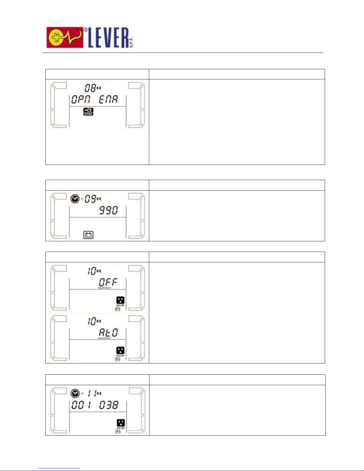
03: Voltage range for bypass
Interface
Setting
Parameter 2: Set the acceptable low voltage for bypass. Setting
range is from 110V to 209V and the default value is 110V.
Parameter 3: Set the acceptable high voltage for bypass. Setting
range is from 231V to 276V and the default value is 264V.
Page 22
21
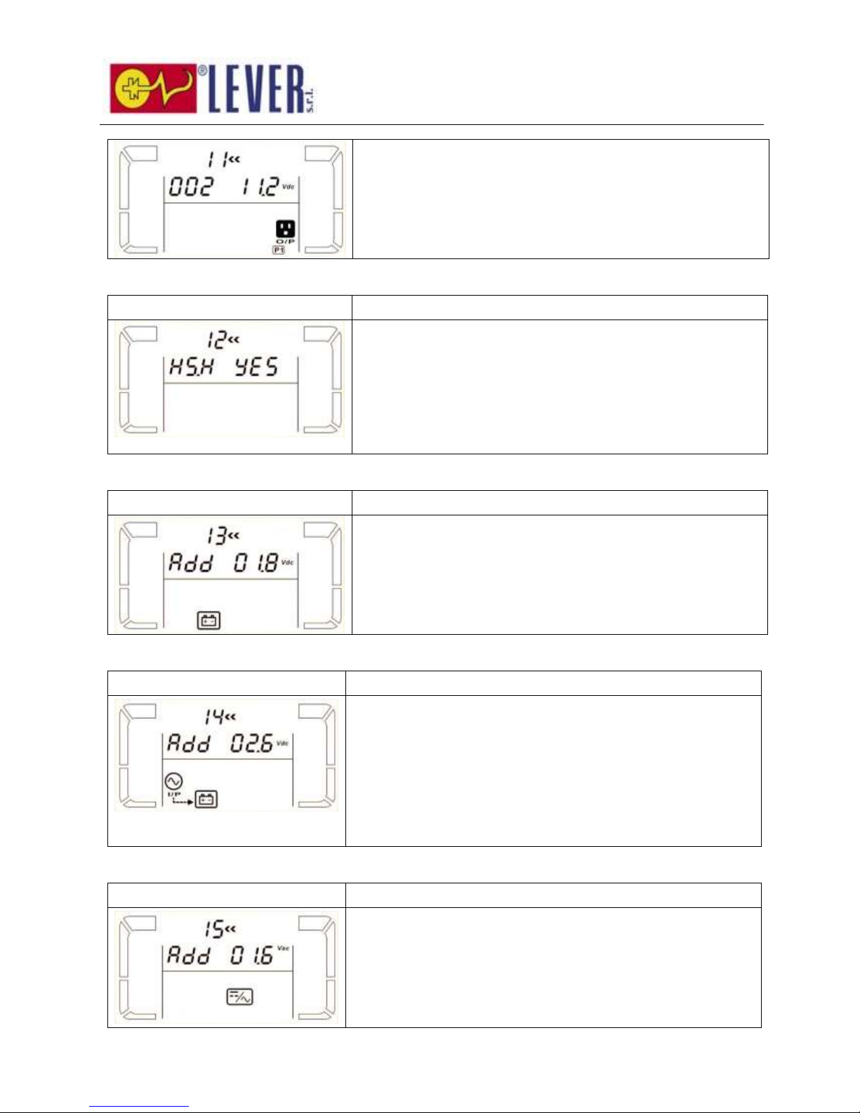
04: Frequency range for bypass
Interface
Setting
Parameter 2: Set the acceptable low frequency for bypass.
50 Hz system: Setting range is from 46.0Hz to 49.0Hz.
60 Hz system: Setting range is from 56.0Hz to 59.0Hz.
The default value is 46.0Hz/56.0Hz.
Parameter 3: Set the acceptable high frequency for bypass.
50 Hz: Setting range is from 51.0Hz to 54.0 Hz.
60 Hz: Setting range is from 61.0Hz to 64.0Hz.
The default value is 54.0Hz/64.0Hz.
05: ECO mode enable/disable
Interface
Setting
Parameter 3: Enable or disable ECO function. You may choose
following two options:
DIS: disable ECO function
ENA: enable ECO function
If ECO function is disabled, voltage range and frequency range for
ECO mode still can be set, but it is meaningless unless the ECO
function is enabled.
06: Voltage range for ECO mode
Interface
Setting
Parameter 2: Low voltage point in ECO mode. The setting range
is from 5% to 10% of the nominal voltage.
Parameter 3: High voltage point in ECO mode. The setting range
is from 5% to 10% of the nominal voltage.
07: Frequency range for ECO mode
Interface
Setting
Parameter 2: Set low frequency point for ECO mode.
50 Hz system: Setting range is from 46.0Hz to 48.0Hz.
60 Hz system: Setting range is from 56.0Hz to 58.0Hz.
The default value is 48.0Hz/58.0Hz.
Parameter 3: Set high frequency point for ECO mode.
50 Hz: Setting range is from 52.0Hz to 54.0 Hz.
60 Hz: Setting range is from 62.0Hz to 64.0Hz.
The default value is 52.0Hz/62.0Hz.
Page 23
22
08: Bypass mode setting
Interface
Setting
Parameter 2:
OPN: Bypass allowed. When selected, UPS will run at Bypass
mode depending on bypass enabled/disabled setting.
FBD: Bypass not allowed. When selected, it’s not allowed for
running in Bypass mode under any situations.
Parameter 3:
ENA: Bypass enabled. When selected, Bypass mode is activated.
DIS: Bypass disabled. When selected, automatic bypass is
acceptable, but manual bypass is not allowed. Manual bypass
means users manually operate UPS for Bypass mode. For
example, pressing OFF button in AC mode to turn into Bypass
mode.
09: Battery backup time setting
Interface
Setting
Parameter 3:
000~999: Set the maximum backup time from 0min to 999min.
UPS will shut down to protect battery after backup time arrives.
The default value is 990min.
DIS: Disable battery discharge protection and backup time will
depend on battery capacity.
10: Programmable output setting
Interface
Setting
Parameter 3: Set programmable output. You may choose the
following three options:
ON: Programmable output is manually switched on timelessly.
OFF: Programmable output is manually switched off. However, if
UPS restarts, this setting will automatically go to “ATO” status.
ATO: Programmable output is automatically turned on or cut off
according to battery or load status. When the battery voltage is
lower than the setting point, or shutdown time arrives, the
programmable output will be cut off automatically. After the utility
is recovering, the output will turn on automatically. If overload
happens, the programmable output also will be cut off
automatically. If it happens 3 times, the programmable output will
be cut off until it is manually switched on.
11: Shutdown point for programmable output
Interface
Setting
Parameter 2: 001.
Set shutdown time for programmable output.
Parameter 3: Shutdown time in minutes.
Setting range is from 0 to 300. When shutdown time arrives, the
programmable output terminal will be cut off. The default value is
30 minutes.
Page 24
23
Parameter 2: 002
Set shutdown voltage for programmable output.
Parameter 3: Shutdown voltage in V.
Setting range is from 11.2 to 13.6. If the battery voltage is less
than the setting point, the programmable output will be cut off.
The default value is 11.2V.
12: Hot standby function enable/disable
Interface
Setting
Parameter 2: HS.H
Enable or disable Hot standby function. You may choose following
two options in Parameter 3:
YES: Hot standby function is enabled. It means that the current
UPS is set to host of the hot standby function, and it will restart
after AC recovery even without battery connected.
NO: Hot standby function is disabled. The UPS is running at
normal mode and can’t restart without battery
13: Battery voltage adjustment
Interface
Setting
Parameter 2: Select “Add” or “Sub” function to adjust battery
voltage to real figure.
Parameter 3: the voltage range is from 0V to 5.7V, the default
value is 0V.
14: Charger voltage adjustment
Interface
Setting
Parameter 2: you may choose Add or Sub to adjust charger
voltage
Parameter 3: the voltage range is from 0V to 9.9V, the default
value is 0V.
NOTE:
*Before making voltage adjustment, be sure to disconnect all
batteries first to get the accurate charger voltage.
*We strongly suggest to use the default value (0). Any
modification should be suitable to battery specifications.
15: Output voltage adjustment
Interface
Setting
Parameter 2: you may choose Add or Sub to adjust inverter
voltage
Parameter 3: the voltage range is from 0V to 6.4V, the default
value is 0V.
Page 25
24
3-8. Operating Mode/Status Description
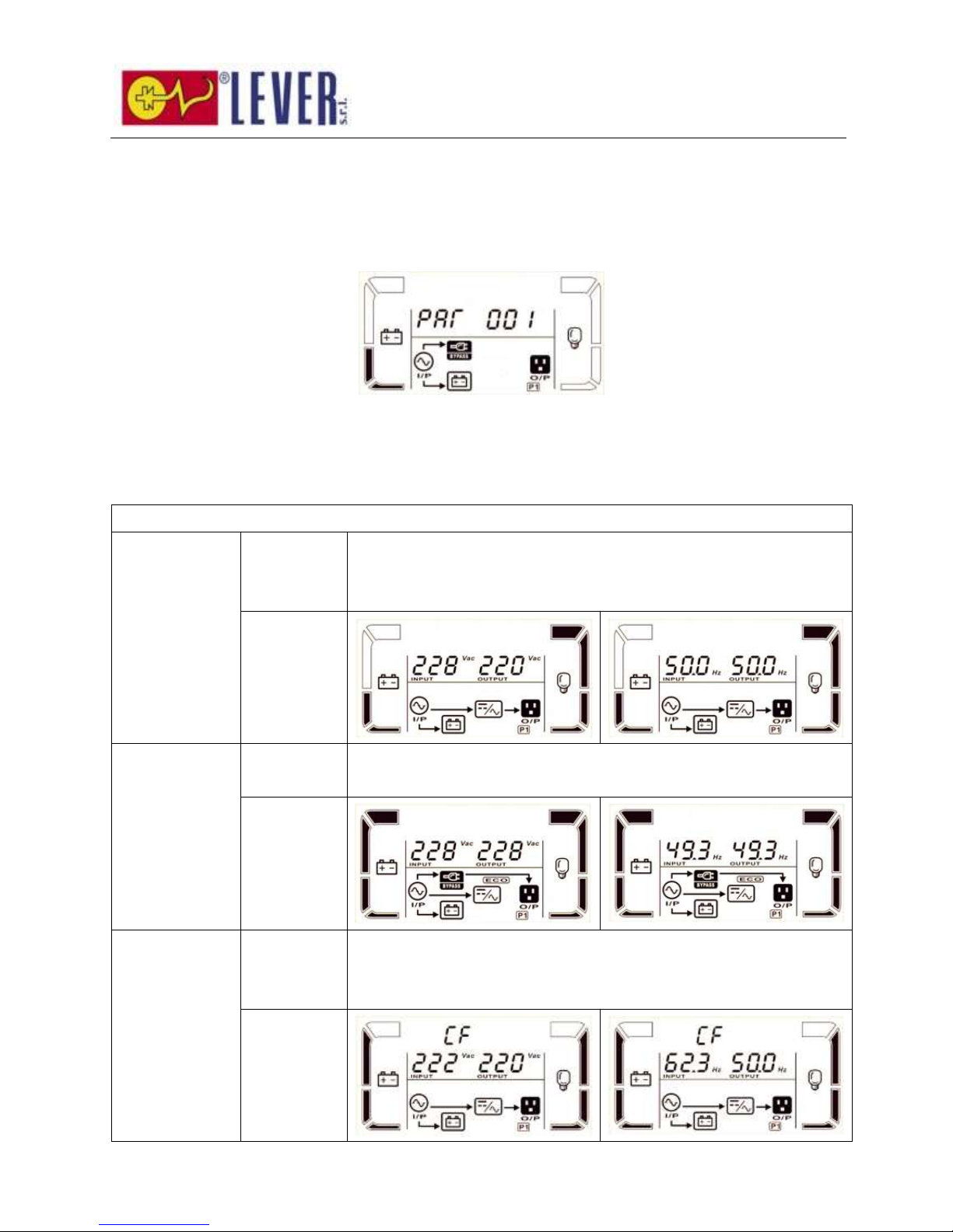
If parallel UPS systems are successfully set up, it will show one more screen with “PAR” in parameter 2 and
be assigned number in parameter 3 as below parallel screen diagram. The master UPS will be default
assigned as “001” and slave UPSs will be assigned as either “002” or “003”. The assigned numbers may be
changed dynamically in the operation;
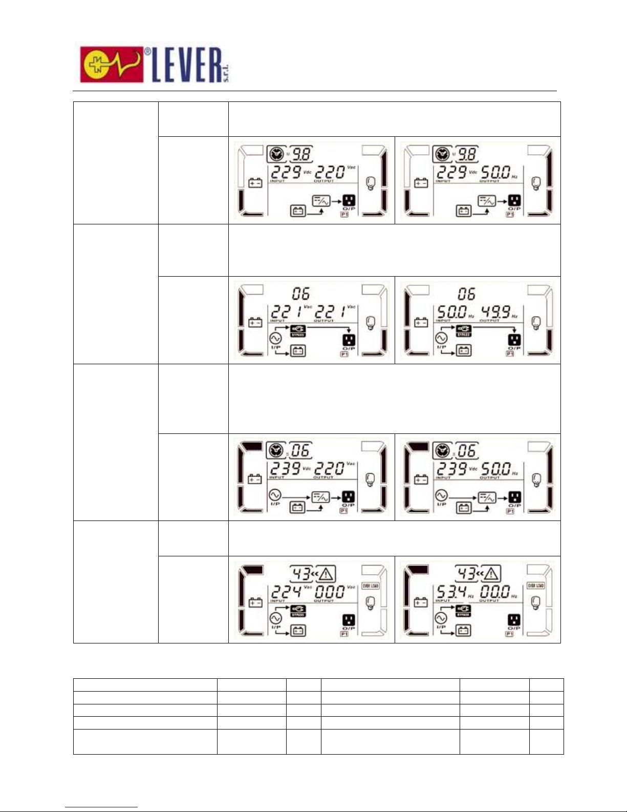
Operating mode/status
AC mode
Description
When the input voltage is within acceptable range, UPS will provide pure
and stable AC power to output. The UPS will also charge the battery at
AC mode.
LCD display
ECO mode
Description
When the input voltage is within voltage regulation range and ECO mode
is enabled, UPS will bypass voltage to output for energy saving.
LCD display
CVCF mode
Description
When input frequency is within 46 to 64Hz, the UPS can be set at a
constant output frequency, 50 Hz or 60 Hz. The UPS will still charge
battery under this mode.
LCD display
Page 26
25
Battery mode
Description
When the input voltage is beyond the acceptable range or power failure,
UPS will backup power from battery and alarm will beep every 4 seconds.
LCD display
Bypass mode
Description
When input voltage is within acceptable range and bypass is enabled,
turn off the UPS and it will enter Bypass mode. Alarm beeps every two
minutes.
LCD display
Battery Test
Description
When UPS is in AC mode or CVCF mode, press “Test” key for more than
0.5s. Then the UPS will beep once and start “Battery Test”. The line
between I/P and inverter icons will blink to remind users. This operation
is used to check the battery status.
LCD display
Fault status
Description
When UPS has fault happened, it will display fault messages in LCD
panel.
LCD display
3-9. Fault Code
Fault event
Fault code
Icon
Fault event
Fault code
Icon
Bus start failure
01
None
Negative power fault
1A
None
Bus over
02
None
Battery SCR short circuited
21
None
Bus under
03
None
Inverter relay short circuited
24
None
Bus unbalance
04
None
Parallel communication
failure
35
None
Page 27
26
Fault event
Fault code
Icon
Fault event
Fault code
Icon
Inverter soft start failure
11
None
Parallel output current
unbalance
36
None
High Inverter voltage
12
None
Over temperature
41
None
Low Inverter voltage
13
None
CPU communication failure
42
None
Inverter output short circuited
14
Overload
43
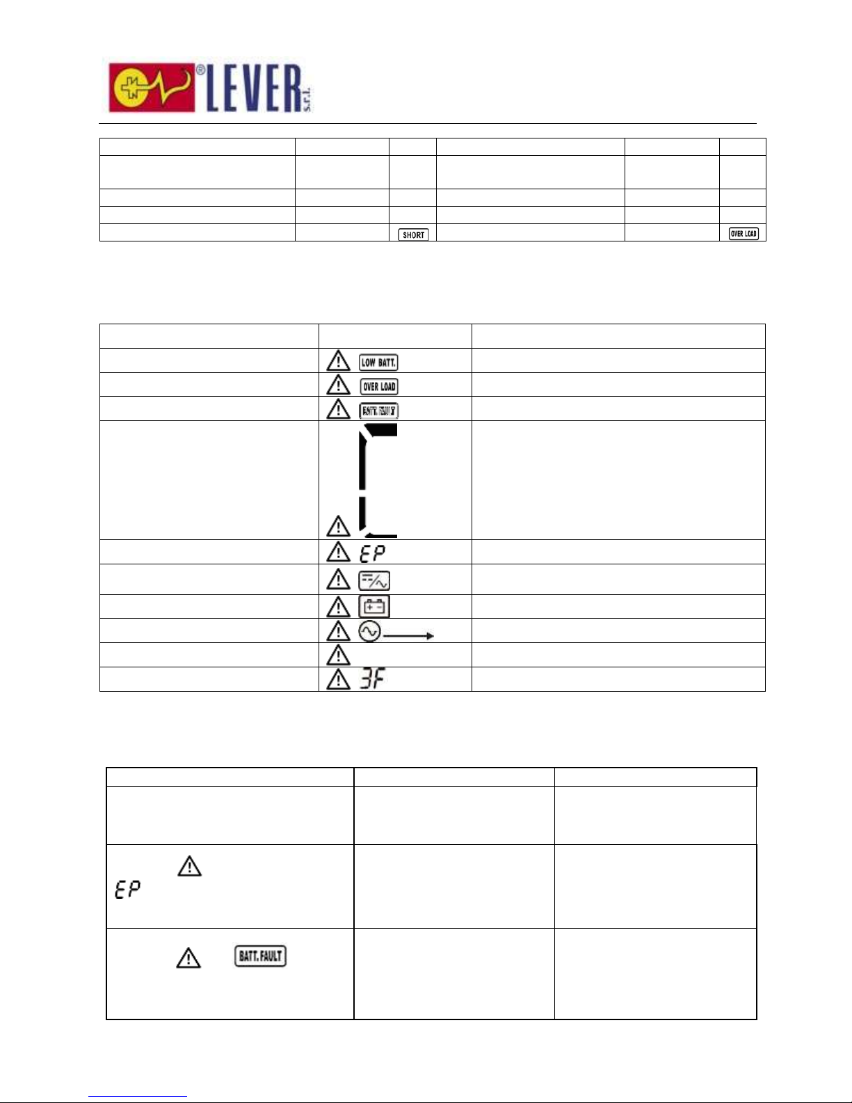
3-10. Warning Indicator
Warning
Icon (flashing)
Alarm
Battery low
Beeping every second
Overload
Beeping twice every second
Battery unconnected
Beeping every second
Over charge
Beeping every second
EPO enable
Beeping every second
Fan failure/Over temperature
Beeping every second
Charger failure
Beeping every second
I/P fuse broken
Beeping every second
Overload 3 times in 30min
Beeping every second
Parallel Protection
Beeping every second
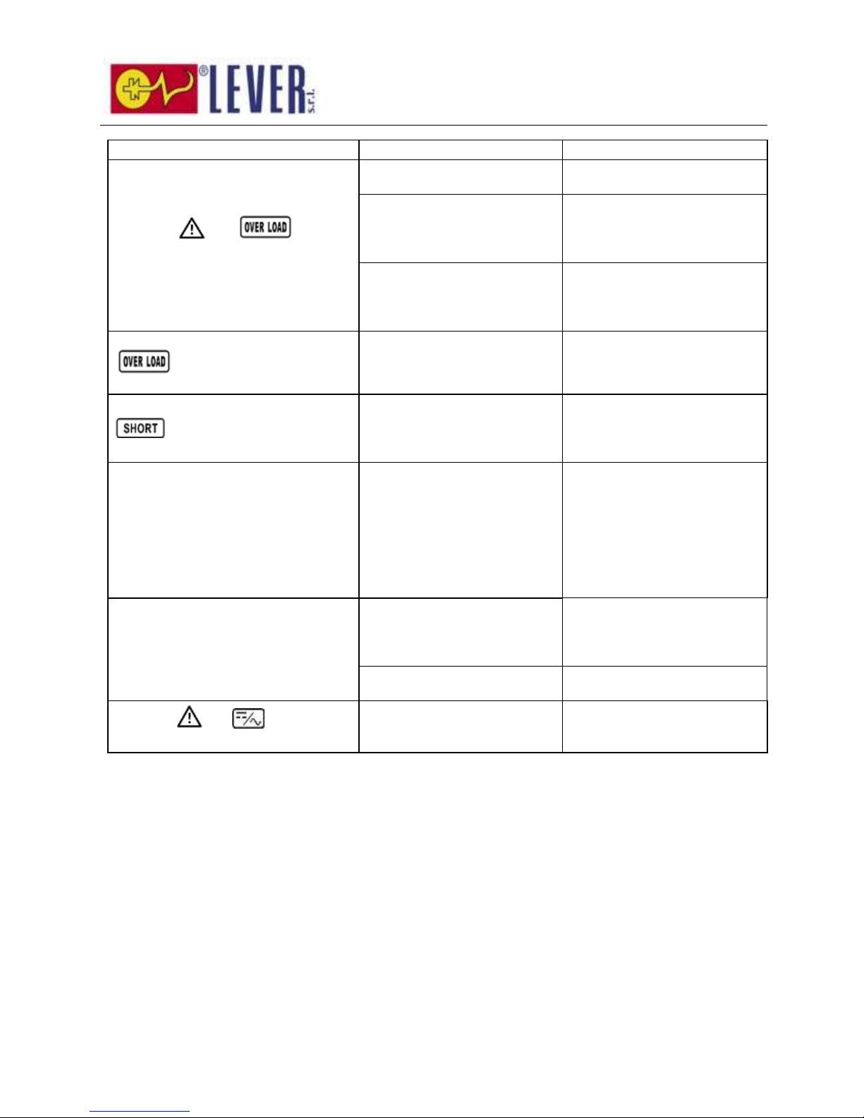
4. Trouble Shooting
If the UPS system does not operate correctly, please solve the problem by using the table below.
Symptom
Possible cause
Remedy
No indication and alarm in the front
display panel even though the mains is
normal.
The AC input power is not
connected well.
Check if input cable firmly
connected to the mains.
The icon and the warning code
flash on LCD display and alarm
beeps every second.
EPO function is enabled.
Set the circuit in closed
position to disable EPO
function.
The icon and flash on
LCD display and alarm beeps every
second.
The external or internal
battery is incorrectly
connected.
Check if all batteries are
connected well.
Page 28
27
Symptom
Possible cause
Remedy
The icon and flash on
LCD display and alarm beeps twice
every second.
UPS is overload.
Remove excess loads from UPS
output.
UPS is overloaded. Devices
connected to the UPS are fed
directly by the electrical
network via the Bypass.
Remove excess loads from UPS
output.
After repetitive overloads, the
UPS is locked in the Bypass
mode. Connected devices are
fed directly by the mains.
Remove excess loads from UPS
output first. Then shut down
the UPS and restart it.
Fault code is shown as 43. The icon
lights on LCD display and
alarm beeps continuously.
UPS is overload too long and
becomes fault. Then UPS shut
down automatically.
Remove excess loads from UPS
output and restart it.
Fault code is shown as 14, the icon
lights on LCD display, and
alarm beeps continuously.
The UPS shut down
automatically because short
circuit occurs on the UPS
output.
Check output wiring and if
connected devices are in short
circuit status.
Fault code is shown as 1, 2, 3, 4, 11,
12, 13, 14,1A, 21, 24, 35, 36, 41, 42 or
43 on LCD display and alarm beeps
continuously.
A UPS internal fault has
occurred. There are two
possible results:
1. The load is still supplied, but
directly from AC power via
bypass.
2. The load is no longer
supplied by power.
Contact your dealer.
Battery backup time is shorter than
nominal value
Batteries are not fully charged
Charge the batteries for at
least 7 hours and then check
capacity. If the problem still
persists, consult your dealer.
Batteries defect
Contact your dealer to replace
the battery.
The icon and flash on LCD
display and alarm beeps every second.
Fan is locked or not working;
or the UPS temperature is too
high.
Check fans and notify dealer.
Page 29
28
Symptom
Possible cause
Remedy
The icon and warning code
flash on LCD display and alarm beeps
every second.
Loose parallel communication
cable or incorrect parallel
operation.
For parallel system, make sure
parallel communication cable is
connected tightly and also
check if the PRA ID number is
right after turning on input
breakers one by one. If all the
number displays are correct,
it’s ok to turn on UPSs after
disabling the warning message
by pressing ‘UP’ and ‘DOWN’
button together. Otherwise,
please do NOT turn on UPSs
and contact your dealer for
help.
For single UPS, since there is
no communication cable and
parallel output cable
connection, simply ignore this
warning message by pressing
‘UP’ and ‘DOWN’ button to
disable and turning on UPS for
continuous operation.
5. Storage and Maintenance
5-1. Storage
Before storing, charge the UPS at least 7 hours. Store the UPS covered and upright in a cool, dry
location. During storage, recharge the battery in accordance with the following table:
Storage Temperature
Recharge Frequency
Charging Duration
-25°C - 40°C
Every 3 months
1-2 hours
40°C - 45°C
Every 2 months
1-2 hours
5-2. Maintenance
The UPS system operates with hazardous voltages. Repairs may be carried out only by qualified
maintenance personnel.
Even after the unit is disconnected from the mains, components inside the UPS system are still
connected to the battery packs which are potentially dangerous.
Before carrying out any kind of service and/or maintenance, disconnect the batteries and verify that
no current is present and no hazardous voltage exists in the terminals of high capability capacitor such as
BUS-capacitors.
Only persons are adequately familiar with batteries and with the required precautionary measures
Page 30
29
may replace batteries and supervise operations. Unauthorized persons must be kept well away from the
batteries.
Verify that no voltage between the battery terminals and the ground is present before maintenance
or repair. In this product, the battery circuit is not isolated from the input voltage. Hazardous voltages may
occur between the battery terminals and the ground.
Batteries may cause electric shock and have a high short-circuit current. Please remove all
wristwatches, rings and other metal personal objects before maintenance or repair, and only use tools
with insulated grips and handles for maintaining or repairing.
When replace the batteries, install the same number and same type of batteries.
Do not attempt to dispose of batteries by burning them. This could cause battery explosion. The
batteries must be rightly deposed according to local regulation.
Do not open or destroy batteries. Escaping electrolyte can cause injury to the skin and eyes. It may
be toxic.
Please replace the fuse only with the same type and amperage in order to avoid fire hazards.
Do not disassemble the UPS system.
Page 31
30
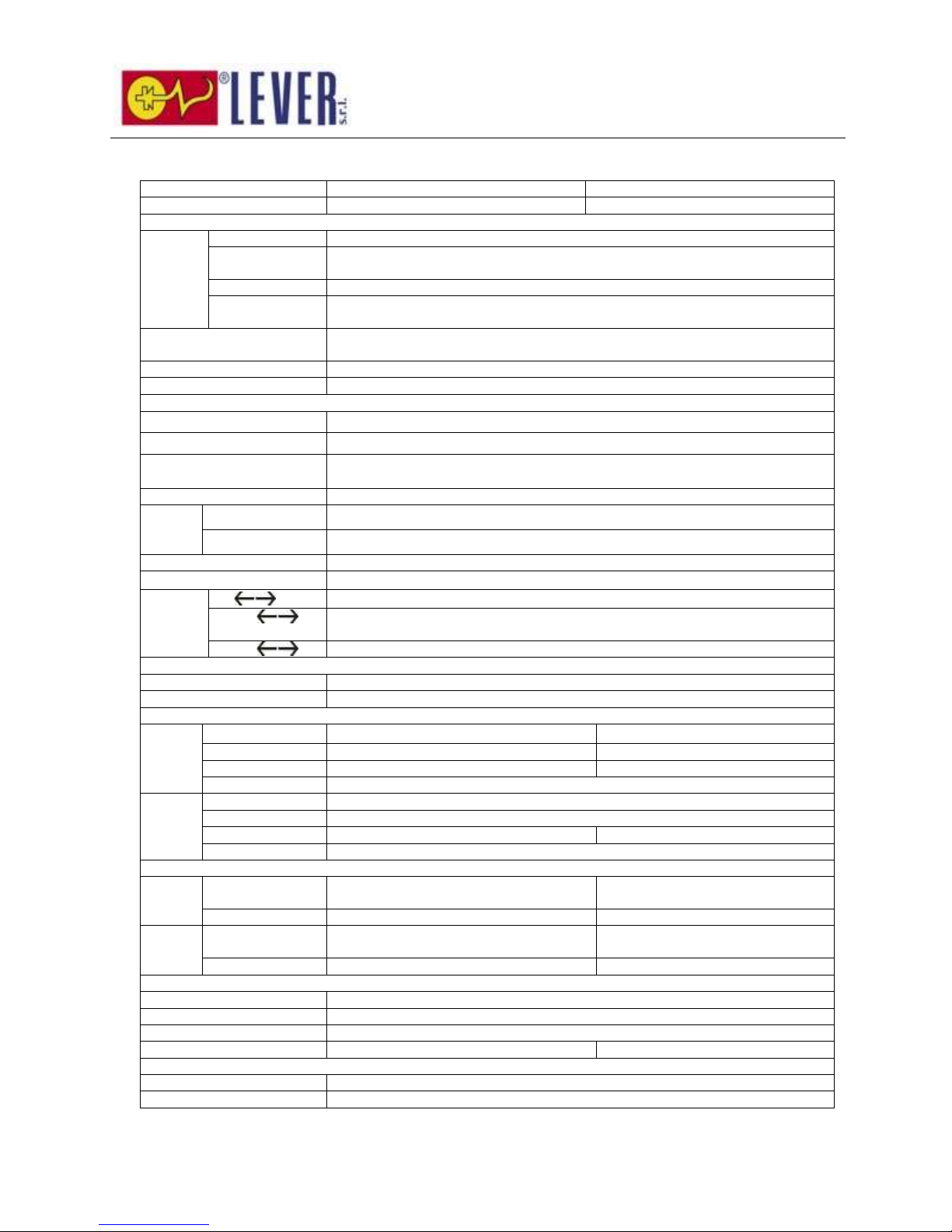
6. Specifications
MODEL
6K
10K
CAPACITY*
6000 VA / 5400 W
10000 VA / 9000 W
INPUT
Voltage
Range
Low Line Loss
110 VAC ± 3 % at 50% Load; 176 VAC ± 3 % at 100% Load
Low Line
Comeback
Low Line Loss Voltage + 10V
High Line Loss
300 VAC ± 3 %
High Line
Comeback
High Line Loss Voltage - 10V
Frequency Range
46Hz ~ 54 Hz @ 50Hz system
56Hz ~ 64 Hz @ 60Hz system
Phase
Single phase with ground
Power Factor
≧ 0.99 at 100% Load
OUTPUT
Output voltage
208/220/230/240VAC
AC Voltage Regulation
± 1%
Frequency Range
(Synchronized Range)
46Hz ~ 54 Hz @ 50Hz system
56Hz ~ 64 Hz @ 60Hz system
Frequency Range (Batt. Mode)
50 Hz ± 0.1 Hz or 60Hz ± 0.1 Hz
Overload
AC mode
100%~110%: 10min、110%~130%: 1min、>130% : 1sec
Battery mode
100%~110%: 30sec、110%~130%: 10sec、>130% : 1sec
Current Crest Ratio
3:1 max
Harmonic Distortion
≦ 3 % @ 100% Linear Load; ≦ 6 % @ 100% Non-linear Load
Transfer
Time
Line Battery
0 ms
Inverter Byp
ass
0 ms
Inverter ECO
<10 ms
EFFICIENCY
AC mode
> 89%
Battery Mode
> 88%
BATTERY
Standard
Model
Type & Numbers
12 V / 7 Ah x 20
12 V / 9 Ah x 20
Recharge Time
7 hours recover to 90% capacity
9 hours recover to 90% capacity
Charging Current
1 A ± 10% (max.)
1 A ± 10% (max.)
Charging Voltage
273 V ± 1%
Long-run
Model
Type
Depending on applications
Numbers
18 - 20
Charging Current
4 A ± 10% (max.)
4 A ± 10% (max.)
Charging Voltage
273 V ± 1%
PHYSICAL
Standard
Model
Dimension,
DXWXH(mm)
592 X 250 X 576
592 X 250 X576
Net Weight (kgs)
81
83
Long-run
Model
Dimension,
DXWXH(mm)
592 X 250 X576
592 X 250 X576
Net Weight (kgs)
25
27
ENVIRONMENT
Operation Temperature
0 ~ 40°C (the battery life will down when > 25°C)
Operation Humidity
<95 % and non-condensing
Operation Altitude**
<1000m
Acoustic Noise Level
Less than 55dB @ 1 Meter
Less than 58dB @ 1 Meter
MANAGEMENT
Smart RS-232 or USB
Supports Windows® 2000/2003/XP/Vista/2008/7/8, Linux, Unix, and MAC
Optional SNMP
Power management from SNMP manager and web browser
* Derate capacity to 60% of capacity in CVCF mode and to 90% when the output voltage is adjusted to 208VAC.
**If the UPS is installed or used in a place where the altitude is above than 1000m, the output power must be derated one percent per 100m.
***Product specifications are subject to change without further notice.
Page 32
31
Serie EC1000
6K/10K UPS Online
Sistema UPS (Uninterruptible Power Supply)
Manuale utente
Page 33

32
Vi preghiamo di rispettare completamente tutti
gli avvisi e le istruzioni operative di questo
manuale. Conservare correttamente questo
manuale e leggere attentamente le istruzioni
seguenti prima di installare l'unità. Non utilizzare
questa unità prima di aver letto attentamente
tutte le informazioni operative e di sicurezza.
Page 34

33
Indice
1. ISTRUZIONI SICUREZZA ED EMC ................................................................................................ 34
1-1. TRASPORTO E STOCCAGGIO .................................................................................................................... 34
1-2. PREPARAZIONE ................................................................................................................................... 34
1-3. INSTALLAZIONE................................................................................................................................... 34
1-4. FUNZIONAMENTO ................................................................................................................................ 35
1-5. STANDARD ........................................................................................................................................ 35
2. INSTALLAZIONE E FUNZIONAMENTO .......................................................................................... 35
2-1. DISIMBALLAGGIO ED ISPEZIONE .............................................................................................................. 36
2-2. VISTA PANNELLO POSTERIORE ................................................................................................................. 36
2-3. INSTALLAZIONE UPS SINGOLO ................................................................................................................ 37
2-4. INSTALLAZIONE UPS PER SISTEMA IN PARALLELO ......................................................................................... 39
2-5. INSTALLAZIONE DEL SOFTWARE ............................................................................................................... 40
3. FUNZIONAMENTO ........................................................................................................................ 40
3-1. FUNZIONI DEL PULSANTE ....................................................................................................................... 40
3-2. INDICATORI LED E PANNELLO LCD .......................................................................................................... 41
3-3. ALLARME SONORO ............................................................................................................................... 43
3-4. FUNZIONAMENTO UPS SINGOLO.............................................................................................................. 44
3-5. FUNZIONAMENTO IN PARALLELO .............................................................................................................. 47
3-6. SIGNIFICATO DELLE ABBREVIAZIONI NEL DISPLAY LCD .................................................................................. 49
3-7. IMPOSTAZIONE LCD ............................................................................................................................ 49
3-8. DESCRIZIONE MODALITÀ/STATO OPERATIVO ............................................................................................... 55
3-9. CODICE GUASTO ................................................................................................................................. 57
3-10. INDICATORE AVVISO .......................................................................................................................... 57
4. RISOLUZIONE DEI PROBLEMI ..................................................................................................... 58
5. STOCCAGGIO E MANUTENZIONE ................................................................................................. 59
5-1. STOCCAGGIO ..................................................................................................................................... 59
5-2. MANUTENZIONE .................................................................................................................................. 59
6. SPECIFICHE ................................................................................................................................. 61
Page 35
34
1. Istruzioni sicurezza ed EMC
Leggere attentamente il seguente manuale utente e le istruzioni di sicurezza prima di installare o usare
l'unità!
1-1. Trasporto e stoccaggio
Trasportare il sistema UPS solo nell'imballaggio originale per proteggerlo da colpi ed urti.
L'UPS deve essere stoccato in ambiente ventilato e secco.
1-2. Preparazione
Se il sistema UPS viene spostato direttamente da un ambiente freddo ad uno caldo si può creare
della condensa. Il sistema UPS deve assolutamente essere asciutto prima di essere installato.
Attendere almeno due ore per consentire l'acclimatazione del sistema UPS nel nuovo ambiente.
Non installare il sistema UPS vicino all'acqua o in ambienti umidi.
Non installare il sistema UPS dove sarebbe esposto a luce solare diretta o vicino ad un calorifero.
Non bloccare i fori di ventilazione nell'alloggiamento dell'UPS.
1-3. Installazione
Non collegare apparecchiature o dispositivi che sovraccaricherebbero il sistema UPS (ad esempio
apparecchiature con grossi motori elettrici) alle prese o terminali di output dell'UPS.
Posizionare i cavi in modo che nessuno possa calpestarli o inciampare su di essi.
Non bloccare le bocchette dell'aria nell'alloggiamento dell'UPS. L'UPS deve essere installato in
una posizione con buona ventilazione. Assicurare uno spazio sufficiente per la ventilazione su ciascun
lato.
L'UPS è munito di terminale messo a terra, nella configurazione finale del sistema installato,
collegamento terra equipotenziale ai cabinet della batteria esterna UPS.
L'UPS può essere installato solo da personale di manutenzione qualificato.
Il cablaggio dell'edificio dovrebbe essere munito di un dispositivo di disconnessione adeguato
come protezione di backup da cortocircuito.
Il cablaggio dell'edificio dovrebbe essere munito di un singolo dispositivo integrato di
interruzione di emergenza che previene ulteriore alimentazione al carico da parte dell'UPS in qualsiasi
modalità operativa.
Collegare la terra prima di effettuare il collegamento al terminale di cablaggio dell'edificio.
L'installazione ed il cablaggio devono essere effettuati in base alle leggi ed alle norme elettriche
locali vigenti.
Page 36
35
1-4. Funzionamento
Non scollegare mai il cavo del conduttore di terra sull'UPS o i terminali di cablaggio dell'edificio,
perché questo annullerebbe la terra protettiva del sistema UPS e di tutti i carichi connessi.
Il sistema UPS dispone di una fonte interna di corrente (batterie). Le prese o le morsettiere di
output dell'UPS possono essere sotto tensione anche se il sistema UPS non è collegato alla presa
elettrica dell'edificio.
Per scollegare completamente il sistema UPS, per prima cosa premere il pulsante “OFF” per
scollegare la rete.
Accertarsi che nessun liquido o altro corpo estraneo possa entrare nel sistema UPS.
L'UPS può essere utilizzato da qualsiasi persona anche priva di esperienza.
1-5. Standard
* Sicurezza
IEC/EN 62040-1
* EMI
Emissione condotta .................................... :IEC/EN 62040-2
Categoria C3
Emissione irradiata ..................................... :IEC/EN 62040-2
Categoria C3
*EMS
ESD ....................................................... :IEC/EN 61000-4-2
Livello 4
RS ......................................................... :IEC/EN 61000-4-3
Livello 3
EFT. ....................................................... :IEC/EN 61000-4-4
Livello 4
SOVRATENSIONE .................................... :IEC/EN 61000-4-5
Livello 4
CS ......................................................... :IEC/EN 61000-4-6
Livello 3
Potenza-frequenza campo magnetico ........ :IEC/EN 61000-4-8
Livello 4
Segnali bassa frequenza............................:IEC/EN 61000-2-2
Avviso: Questo è un prodotto per uso commerciale ed industriale. A seconda
dell'ambiente possono essere necessarie restrizioni relative all'installazione o
misure aggiuntive per prevenire disturbi.
2. Installazione e funzionamento
Esistono due tipi diversi di UPS online: standard ed a lunga autonomia. Fare riferimento alla seguente tabella
dei modelli.
Modello
Tipo
Modello
Tipo
6K
Standard
6K-SC
Lunga
autonomia
10K
10K-SC
Il funzionamento in parallelo è disponibile anche per questi due tipi. L'installazione ed il funzionamento in
parallelo saranno descritti in dettaglio in seguito.
Page 37
36
2-1. Disimballaggio ed ispezione
Disimballare e verificare il contenuto dell'imballaggio. L'imballaggio di spedizione contiene:
● Un UPS
● Un manuale utente
● Un CD con il software di monitoraggio
● Un cavo RS-232 (opzionale)
● Un cavo USB
● Un cavo parallelo (disponibile solo per modello parallelo)
● Un cavo corrente condiviso (disponibile solo per modello parallelo)
● Un cavo batteria (opzione)
NOTA: Prima dell'installazione, ispezionare l'unità. Accertarsi che durante il trasporto non risulti
danneggiato nulla all'interno dell'imballaggio. Non accendere l'unità ed avvertire immediatamente il
trasportatore ed il rivenditore in caso di danni o mancanza di alcune parti. Conservare l'imballaggio originale
in un luogo sicuro per uso futuro.
2-2. Vista pannello posteriore
Diagramma 1: 6k(SC)/10k(SC)
Pannello posteriore
Diagramma 2: Terminali di Input/Output
6k(SC)/10k(SC)
1. Porta di comunicazione RS-232
2. Porta di comunicazione USB
3. Funzione di spegnimento di emergenza (connettore EPO)
4. Porta di corrente condivisa (disponibile solo per modello parallelo)
Page 38

37
5. Porta parallelo (disponibile solo per modello parallelo)
6. Slot intelligente
7. Ventola di raffreddamento
8. Porta esterna interruttore bypass manutenzione
9. Interruttore di bypass di manutenzione
10. Interruttore di circuito input
11. Prese di output: connessione a carichi critici
12. Interruttore output per prese
13. Terminale input/output (per i dettagli fare riferimento a diagramma 2, 4, 6)
14. Terminale di output: connessione a carichi critici
15. Terminale di output programmabile: connessione a carichi non critici
16. Connettore batteria esterna
17. Terminale di input rete
2-3. Installazione UPS singolo
L'installazione e il cablaggio devono essere effettuati secondo le leggi/norme elettriche locali in vigore da
parte di personale professionale che segua le seguenti istruzioni.
1) Accertarsi che i fili e gli interruttori di rete nell'edificio siano sufficienti per la capacità nominale dell'UPS,
per evitare i pericoli di scossa elettrica o incendio.
NOTA: Non usare la presa a muro come fonte di alimentazione per l'UPS, in quanto la sua corrente nominale
è inferiore alle corrente di input massima dell'UPS. Altrimenti la presa potrebbe incendiarsi e distruggersi.
2) Mettere su off l'interruttore di rete dell'edificio prima dell'installazione.
3) Spegnere tutti i dispositivi connessi prima del collegamento all'UPS.
4) Preparare i fili in base alla seguente tabella:
Modello
Specifiche fili (mm2)
Input
Output
Batteria
Terra
6k
10
10 10
6kL
10
10
10
10
10k
16
16 16
10kL
16
16
16
16
NOTA 1: Il cavo per 6k/6kL dovrebbe essere in grado di sopportare una corrente di oltre 40A. Si
raccomanda di usare un filo 10 mm2 o più spesso per garantire sicurezza ed efficienza.
NOTA 2: Il cavo per 10k/10kL dovrebbe essere in grado di sopportare una corrente di oltre 63A. Si
raccomanda di usare un filo 16 mm2 o più spesso per garantire sicurezza ed efficienza.
NOTA 3: La scelta dei colori dei fili deve seguire le leggi e norme elettriche locali in vigore.
5) Rimuovere il coperchio della morsettiera sul pannello posteriore dell'UPS. Quindi collegare i fili in base ai
diagrammi della morsettiera: (Quando si effettua la connessione dei fili, per prima cosa collegare il filo di
terra. (Quando si effettua la disconnessione dei fili, per prima cosa scollegare il filo di terra.
Page 39
38
Diagramma cablaggio morsettiera
NOTA 1: Accertarsi che i fili siano connessi in modo sicuro ai terminali.
NOTA 2: Ci sono due tipi di output: terminale/prese di output e terminale programmabile. Collegare i
dispositivi non critici al terminale programmabile e i dispositivi critici ai terminali/prese di output. In caso di
mancanza di energia elettrica, è possibile estendere i tempi di backup per i dispositivi critici impostando un
tempo di backup più breve per i dispositivi non critici.
NOTA 3: Installare l'interruttore di output tra il terminale di output ed il carico. L'interruttore dovrebbe
essere qualificato con funzione protettiva corrente di dispersione se necessario.
6) Rimettere il coperchio della morsettiera sul pannello posteriore dell'UPS.
Avviso: (Solo per modello standard)
● Prima dell'installazione, accertarsi che l'UPS non sia acceso. L'UPS non dovrebbe essere acceso durante
la connessione del cablaggio.
● Non cercare di trasformare il modello standard in modello a lunga autonomia. In particolare, non
cercare di connettere la batteria interna standard alla batteria esterna. Il tipo e la tensione delle batterie
possono essere diversi. Collegarle insieme potrebbe generare un pericolo di scossa elettrica o incendio!
Avviso: (Solo per modello a lunga autonomia)
● Accertarsi che sia installato un interruttore DC o altro dispositivo di protezione tra l'UPS e il pacco
batterie esterno. Altrimenti, installarlo attentamente. Mettere su off l'interruttore di batteria prima
dell'installazione.
Avviso:
● Per un pacco batterie standard, è presente un interruttore DC per scollegare il pacco batterie e l'UPS. Ma
per l'altro pacco batterie esterno, accertarsi che sia installato un interruttore DC o altro dispositivo di
protezione tra l'UPS ed il pacco batterie esterno. Altrimenti, installarlo attentamente. Mettere su off
l'interruttore di batteria prima dell'installazione.
NOTA: Mettere l'interruttore del pacco batterie in posizione “OFF” e quindi installare il pacco batterie.
● Fare particolare attenzione alla tensione nominale della batteria indicata sul pannello posteriore. Se si
desidera modificare il numero di batterie del pacco, accertarsi di modificare le impostazioni
Input Neutro
Input Linea
Output 2 Neutro
Output 2 Linea
Output 1 Neutro
Output 1 Linea
Page 40

39
contemporaneamente. La connessione con tensione di batteria errata può causare danno permanente
all'UPS. Accertarsi che la tensione del pacco batterie sia corretta.
● Fare particolare attenzione al segno della polarità sulla morsettiera della batteria esterna ed accertarsi
che sia connessa la polarità corretta della batteria. Una connessione errata può causare danno
permanente all'UPS.
● Accertarsi che il cablaggio di terra protettivo sia corretto. Controllare attentamente la specifica di
corrente, il colore, la posizione, la connessione e l'affidabilità della conduttanza del filo.
● Accertarsi che il cablaggio di input ed output della rete sia corretto. Controllare attentamente la specifica
di corrente, il colore, la posizione, la connessione e l'affidabilità della conduttanza del filo. Accertarsi che
la posizione L/N sia corretta, non invertita o cortocircuitata.
2-4. Installazione UPS per sistema in parallelo
Se l'UPS è disponibile solo per funzionamento singolo, è possibile saltare questa sezione e passare a quella successiva.
1) Installare e cablare gli UPS in base alla sezione 2-3.
2) Collegare i fili di output di ciascun UPS ad un interruttore di output.
3) Collegare tutti gli interruttori di output ad un interruttore di output principale. Quindi questo interruttore
di output principale si collegherà direttamente ai carichi.
4) Ciascun UPS è connesso ad un pacco batterie indipendente.
5) Rimuovere il coperchio della porta del cavo di corrente parallelo condiviso sull'UPS, collegare ciascun
UPS uno ad uno con il cavo parallelo ed il cavo di corrente condiviso, e quindi riavvitare il coperchio.
NOTA: Il sistema in parallelo non può usare un pacco batterie. Questo provocherebbe un guasto
permanente.
6) Fare riferimento al seguente diagramma di cablaggio:
Page 41
40
Diagramma 1: Connessione cavo alimentazione
2-5. Installazione del software
Per una protezione ottimale, installare il software di monitoraggio dell'UPS per configurare completamente
l'arresto dell'UPS.
3. Funzionamento
3-1. Funzioni del pulsante
Pulsante
Funzione
Pulsante ON/Enter
Accende l'UPS: Tenere premuto questo pulsante per almeno 0,5 secondi
per accendere l'UPS.
Tasto Enter: Premere questo pulsante per confermare la selezione nel
menu delle impostazioni.
Pulsante OFF/ESC
Spegne l'UPS: Tenere premuto questo pulsante per almeno 0,5 secondi per
spegnere l'UPS.
Tasto Esc: Premere questo pulsante per ritornare all'ultimo menu nel menu
delle impostazioni.
Diagramma 2
Connessione porta comunicazione parallela
Connessione cavo corrente condiviso
Page 42
41
Pulsante
Funzione
Pulsante Test/Up
Test batteria: Tenere premuto questo pulsante per almeno 0,5 secondi per
testare la batteria in modalità AC, o modalità CVCF.
Tasto UP: Premere questo pulsante per visualizzare la selezione successiva
nel menu impostazione.
Pulsante
Mute/Down
Disattiva l'allarme: Tenere premuto questo pulsante per almeno 0,5 secondi
per disattivare l'allarme. Per maggiori informazioni fare riferimento alla
sezione 3-4-9.
Tasto Down: Premere questo pulsante per visualizzare la selezione
precedente nel menu impostazione.
Pulsante Test/Up +
Mute/Down
Tenere premuti contemporaneamente i due pulsanti per almeno 1 secondo
per entrare/uscire dal menu di impostazione.
* Modalità CVCF significa modalità convertitore.
3-2. Indicatori LED e pannello LCD
Indicatori LED:
Il pannello anteriore ospita 4 LED che mostrano lo stato di lavoro dell'UPS:
Modalità LED
Bypass
Linea
Batteria
Guasto
Accensione UPS
● ● ●
●
Modalità Bypass
●
○
○
○
Modalità AC
○ ● ○
○
Modalità batteria
○
○ ● ○
Modalità CVCF
○ ● ○
○
Test batteria
● ● ●
○
Modalità ECO
● ● ○
○
Guasto
○
○
○
●
Nota: ● significa che il LED è acceso, e ○ significa che il LED è spento.
Pannello LCD
Indicatori LED
Page 43
42
Pannello LCD:
Display
Funzione
Informazione tempo backup
Indica l'autonomia della batteria in numeri.
H: ore, M: minuti, S: secondi
Informazioni guasto
Indica che si è verificato un avviso ed un guasto.
Indica i codici di guasto. I codici sono elencati in dettaglio nella sezione 3-9.
Funzionamento in Mute
Indica che l'allarme UPS è disabilitato.
Informazione tensione output & batteria
Indica la tensione di output, la frequenza di output o la tensione della
batteria.
Vac: tensione di output, Vdc: tensione della batteria, Hz: frequenza
Informazione carico
Indica il livello del carico: 0-25%, 26-50%, 51-75%, 76-100%.
Indica sovraccarico.
Indica che il carico o l'output è in cortocircuito.
Informazioni sull'output programmabile
Indica che gli output programmabili stanno funzionando.
Informazioni modalità operativa
Indica che l'UPS è collegato alla rete.
Page 44
43
Indica che la batteria sta funzionando.
Indica che il circuito di bypass sta funzionando.
Indica che la modalità ECO è abilitata.
Indica che il circuito dell'Inverter sta funzionando.
Indica che l'output sta funzionando.
Informazioni sulla batteria
Indica la capacità della batteria: 0-25%, 26-50%, 51-75%, 76-100%.
Indica che la batteria non è connessa.
Indica un livello della batteria basso ed una tensione della batteria bassa.
Informazione tensione input e batteria
Indica la tensione o frequenza di ingresso o la tensione della batteria.
Vac: Tensione di input, Vdc: tensione batteria, Hz: frequenza di input
3-3. Allarme sonoro
Descrizione
Stato buzzer
Inattivo
Stato UPS
Modalità Bypass
bip ogni 2 minuti
Sì
Modalità batteria
bip ogni 4 secondi
Modalità guasto
bip continuamente
Avviso
Sovraccarico
Bip due volte al secondo
No
Batteria scarica
Bip una volta al secondo
Batteria non collegata
Carica eccessiva
Abilita EPO
Guasto ventola/Temperatura eccessiva
Guasto caricatore
Fusibile IP rotto
Sovraccarico 3 volte in 30min
Stato EPO
Il coperchio dell'interruttore di
mantenimento è aperto
Protezione parallelo
Guasto
Errore avvio bus
Bip continuamente
Sì
Bus sopra
Bus sotto
Sbilanciamento bus
Mancato soft start inverter
Alta tensione inverter
Page 45

44
Bassa tensione inverter
Bip continuamente
SI
Output inverter in cortocircuito
Guasto negativo alimentazione
Batteria SCR in corto circuito
Relé inverter in corto circuito
Guasto comunicazione parallelo
Sbilanciamento corrente output
parallelo
Temperatura eccessiva
Guasto comunicazione CPU
Sovraccarico
3-4. Funzionamento UPS singolo
1. Accendere l'UPS con alimentazione di rete (in modalità AC)
1) Dopo che l'alimentazione è regolarmente connessa, mettere l'interruttore del pacco batterie in
posizione “ON” (disponibile solo nel modello a lunga autonomia). Quindi mettere l'interruttore di
input in posizione “ON”. In questo momento la ventola è in funzione e l'UPS fornisce alimentazione
ai carichi tramite il bypass. L'UPS sta funzionando in modalità Bypass.
NOTA: Quando l'UPS è in modalità Bypass, la tensione di output si alimenterà direttamente dalla
rete dopo aver aperto l'interruttore di input. In modalità Bypass, il carico non è protetto dall'UPS. Per
proteggere i dispositivi, accendere l'UPS. Fare riferimento al passaggio successivo.
2) Tenere premuto il tasto “ON” per 0,5s per accendere l'UPS. Il buzzer farà bip una volta.
3) Pochi secondi dopo, l'UPS entrerà in modalità AC. Se l'alimentazione di rete è anormale, l'UPS
opererà in modalità Batteria senza interruzione.
NOTA: Quando l'UPS sta esaurendo la batteria, si arresterà automaticamente in modalità Batteria.
Quando l'alimentazione di rete viene ripristinata, l'UPS si riavvierà automaticamente in modalità AC.
2. Accendere l'UPS senza alimentazione di rete (in modalità Batteria)
1) Accertarsi che l'interruttore del pacco batterie sia in posizione “ON” (solo per modello a lunga
autonomia).
2) Tenere premuto il tasto “ON” per 0,5s per accendere l'UPS. Il buzzer farà bip una volta.
3) Pochi secondi più tardi, l'UPS si attiverà ed entrerà in modalità Batteria.
3. Collegare i dispositivi all'UPS
Dopo che l'UPS è attivo, è possibile collegare dispositivi all'UPS.
1) Per prima cosa accendere l'UPS e quindi accendere i dispositivi uno ad uno. Il pannello LCD
visualizzerà il livello totale del carico.
2) Se è necessario collegare carichi induttivi come una stampante, la corrente di spunto deve essere
calcolata attentamente per vedere se soddisfa la capacità dell'UPS, perché il consumo di questo
tipo di carichi è eccessivo.
3) Se l'UPS è sovraccarico, il buzzer farà bip due volte al secondo.
4) Quando l'UPS è sovraccarico, rimuovere immediatamente alcuni carichi. Si raccomanda che i carichi
Page 46

45
totali connessi all'UPS siano inferiori all'80% della sua capacità nominale per prevenire il
sovraccarico per la sicurezza del sistema.
5) Se il tempo di sovraccarico è superiore al tempo accettabile elencato nelle specifiche in modalità AC,
l'UPS passerà automaticamente in modalità Bypass. Dopo la rimozione del sovraccarico, tornerà
in modalità AC. Se il tempo di sovraccarico è superiore al tempo accettabile elencato nelle
specifiche in modalità Batteria, l'UPS passerà in stato Guasto. In quel momento, se il bypass è
abilitato, l'UPS alimenterà il carico tramite bypass. Se la funzione bypass è disabilitata o
l'alimentazione di input non è all'interno del range accettabile per il bypass, disattiverà direttamente
l'output.
4. Caricare le batterie
1) Dopo che l'UPS è collegato alla rete, il caricatore caricherà automaticamente le batterie, eccetto in
modalità Batteria o durante il test automatico della batteria.
2) Suggeriamo di caricare le batterie almeno 10 ore prima dell'uso. Altrimenti, il tempo di backup può
essere inferiore al tempo atteso.
3) Verificare che l'impostazione del numero di batterie sulla scheda di controllo (per maggiori
informazioni sulle impostazioni, fare riferimento alla sezione 3-4-12) corrisponda alla connessione
reale.
5. Funzionamento in modalità batteria
1) Quando l'UPS è in modalità Batteria, il buzzer farà bip in base alla diversa capacità della batteria. Se
la capacità della batteria è superiore a 25%, il buzzer farà bip una volta ogni 4 secondi; se la
tensione della batteria scende al livello di allarme, il buzzer farà bip velocemente (una volta la
secondo) per ricordare agli utenti che la batteria è ad un livello basso e che l'UPS presto si spegnerà
automaticamente. Gli utenti possono disattivare alcuni carichi non critici per disabilitare l'allarme di
spegnimento e prolungare il tempo di backup (l'UPS disabilita automaticamente il terminale di
output programmabile quando la funzione timer programmabile è abilitata). Se non ci sono altri
carichi da disattivare in quel momento, è necessario disattivare tutti i carichi appena possibile per
proteggere i dispositivi o salvare i dati. Altrimenti, esiste il rischio di perdita dei dati o guasto del
carico.
2) In modalità batteria, se il suono del buzzer disturba, gli utenti possono premere il pulsante Mute per
disabilitare il buzzer.
3) Il tempo di backup time del modello a lunga autonomia dipende dalla capacità della batteria
esterna.
4) Il tempo di backup può variare a seconda della temperatura ambiente e del tipo di carico.
5) Quando si imposta il tempo di backup a 16,5 ore (valore di default da pannello LCD), dopo il
funzionamento per 16,5 ore, l'UPS si arresterà automaticamente per proteggere la batteria. La
protezione contro l'esaurimento della batteria può essere abilitata o disabilitata tramite il pannello
di controllo LCD. (Fare riferimento alla sezione 3-7 Impostazione LCD)
6. Test delle batterie
1) Se è necessario controllare lo stato della batteria quando l'UPS funziona in modalità AC/CVCF/ECO,
premere il pulsante “Test” per fare in modo che l'UPS effettui il test automatico della batteria.
Page 47

46
2) Per mantenere l'affidabilità del sistema, l'UPS effettuerà automaticamente un test periodico. La
frequenza predefinita è una volta alla settimana.
3) Gli utenti possono impostare il test automatico della batteria anche tramite il software di
monitoraggio.
4) Se l'UPS sta effettuando il test automatico della batteria, l'indicazione del display LCD e del buzzer
sarà la stessa della modalità Batteria, eccetto che il LED della batteria lampeggia.
7. Spegnere l'UPS con alimentazione di rete in modalità AC
1) Spegnere l'inverter dell'UPS premendo il pulsante “OFF” per almeno 0,5s. Il buzzer farà bip una
volta. L'UPS passerà in modalità Bypass.
NOTA 1: Se l'UPS è stato impostato per abilitare il bypass dell'output, bypasserà la tensione dalla
rete alle prese ed ai terminali di output anche se l'UPS (inverter) è stato spento.
NOTA 2: Dopo avere spento l'UPS, sappiate che l'UPS sta funzionando in modalità Bypass e che c'è
il rischio di perdita di alimentazione per i dispositivi connessi.
2) In modalità Bypass, la tensione di output dell'UPS rimane presente. Per disattivare l'output, mettere
l'interruttore di input su off. Pochi secondi dopo, sul pannello display non appare niente e l'UPS è
completamente spento.
8. Spegnere l'UPS senza alimentazione di rete in modalità Batteria
1) Spegnere l'UPS tenendo premuto il pulsante “OFF” per almeno 0,5s. Il buzzer farà bip una volta.
2) L'UPS disattiverà l'alimentazione all'output e sul pannello display non appare nulla.
9. Disattivare l'allarme
1) Per disattivare l'allarme, premere il pulsante “Mute” per almeno 0,5s. Se si preme nuovamente il
pulsante dopo la disattivazione del buzzer, il buzzer farà nuovamente bip.
2) Alcuni allarmi non possono essere disattivati sino a che l'errore non viene risolto. Per maggiori
informazioni fare riferimento alla sezione 3-3.
10. Funzionamento in stato avviso
1) Quando il LED guasto lampeggia ed il buzzer fa bip una volta al secondo, significa che ci sono dei
problemi per il funzionamento dell'UPS. Gli utenti possono rilevare il codice guasto dal pannello LCD.
Per maggiori informazioni, consultare la tabella risoluzione problemi nel capitolo 4.
2) Alcuni allarmi non possono essere disattivati sino a che l'errore non viene risolto. Per maggiori
informazioni fare riferimento alla sezione 3-3.
11. Funzionamento in modalità Guasto
1) Quando il LED Guasto si illumina ed il buzzer fa bip in modo continuo, significa che l'UPS ha un
guasto grave. Gli utenti possono rilevare il codice guasto dal pannello display. Per maggiori
informazioni, consultare la tabella risoluzione problemi nel capitolo 4.
2) Verificare carichi, cablaggio, ventilazione, rete, batteria, ecc. dopo che si è verificato il guasto. Non
cercare di attivare nuovamente l'UPS prima di aver risolto i problemi. Se i problemi non possono
essere risolti, contattare immediatamente il distributore o il personale dell'assistenza.
Page 48

47
3) In caso di emergenza, disconnettere immediatamente la rete, la batteria esterna, e l'output per
evitare maggiori rischi e pericoli.
12. Modifica del numero di batterie
1) Questa operazione è disponibile solo a tecnici professionali o qualificati.
2) Spegnere l'UPS. Se non è possibile rimuovere il carico, è necessario rimuovere il coperchio
dell'interruttore di bypass per la manutenzione sul pannello posteriore e mettere l'interruttore di
manutenzione per prima cosa in posizione “BPS”.
3) Mettere l'interruttore di input su off, e mettere su off l'interruttore della batteria (disponibile solo dei
modelli a lunga autonomia).
4) Rimuovere il cabinet, quindi modificare il jumper sulla scheda di controllo per impostare il numero
di batterie (fare riferimento alla NOTA sotto). Quindi disconnettere il filo della batteria per il modello
standard e modificare con attenzione il pacco batterie. Dopo aver completato le modifiche,
riposizionare il cabinet.
NOTA: Impostazione JP1 sulla scheda di controllo: chiudere i Pin5 e Pin6 e Pin7 e Pin8 per batterie a 20
elementi; chiudere il Pin5 e Pin6 e tenere i Pin7 e Pin8 aperti per batterie a 19 elementi; e tenere tutti i
pin aperti per batterie a 18 elementi.
5) Mettere l'interruttore di input su on. L'UPS entrerà in modalità Bypass. Se l'UPS è in modalità Bypass
manutenzione, posizionare l'interruttore manutenzione in posizione “UPS” e quindi accendere
l'UPS.
3-5. Funzionamento in parallelo
1. Connessione sistema in parallelo
1) Accertarsi che tutti gli UPS siano modelli paralleli, e seguire il cablaggio indicato nella sezione 2-4.
2) Mettere su off gli interruttori di input e di output di ciascun UPS, e mettere su off l'interruttore della
batteria se l'UPS è un modello a lunga autonomia.
3) Mettere su on l'interruttore di input di ciascun UPS e misurare con multimetro la differenza di
tensione tra l'output linea 1 di ciascun UPS. Se la differenza di tensione è inferiore a 1V, significa
che tutte le connessioni sono corrette. Se la differenza è superiore a 1V, verificare la corretta
connessione dei cablaggi.
4) Mettere su on gli interruttori di input di tutti gli UPS nei sistemi paralleli. Prima di attivare in
sequenza ciascun UPS, verificare se PAR001~PAR003 vengono visualizzati in ciascun UPS in
sequenza. Se nessun “PAR××” esiste in nessun UPS, verificare se i cavi paralleli sono collegati
correttamente.
5) Attivare in sequenza ciascun UPS ed accertarsi che il LED modalità AC o il LED modalità Batteria si
accenda in ciascun UPS. Misurare la tensione di output di ciascun UPS per verificare se la differenza
di tensione è inferiore a 2V (valore tipico 1V) con multimetro. Se la differenza è superiore a 2V,
verificare che il cavo parallelo o il cavo corrente condiviso siano collegati correttamente. Se sono
tutti collegati correttamente, forse si tratta di un problema interno dell'UPS. Contattare il proprio
distributore o servizio assistenza locale per ottenere assistenza.
6) Spegnere ciascun UPS in sequenza, metterli tutti in modalità Bypass, mettere su on l'interruttore di
Page 49

48
output di ciascuna unità.
7) Accendere gli UPS in modalità AC e quindi il collegamento del sistema parallelo è completato.
2. Aggiungere una nuova unità al sistema parallelo
1) Non è possibile aggiungere una nuova unità al sistema parallelo quando l'intero sistema è in
funzione. È necessario rimuovere il carico e spegnere il sistema.
2) Accertarsi che tutti gli UPS siano modelli paralleli, e seguire il cablaggio indicato nella sezione 2-3.
3) Installare il nuovo sistema parallelo facendo riferimento alla sezione precedente.
3. Rimozione di una unità dal sistema parallelo
Esistono due metodi per rimuovere un'unità dal sistema parallelo:
Primo metodo:
4) Premere due volte il tasto “OFF”, ogni volta per almeno 0,5. L'UPS entrerà quindi in modalità bypass
senza output.
5) Mettere su off l'interruttore di output di questa unità, e quindi mettere su off l'interruttore di input di
questa unità.
6) Dopo che si spegne, è possibile mettere su off l'interruttore della batteria (per modello a lunga
autonomia) e rimuovere il cavo parallelo e il cavo di corrente condiviso. Quindi rimuovere l'unità dal
sistema parallelo
Secondo metodo:
1) Se il bypass è anomalo, non è possibile rimuovere l'UPS senza interruzione. È necessario rimuovere
il carico e spegnere il sistema.
2) Accertarsi che l'impostazione bypass sia abilitata in ciascun UPS e quindi spegnere il sistema. Tutti
gli UPS passeranno in modalità Bypass. Rimuovere tutti i coperchi bypass manutenzione ed
impostare gli interruttori di manutenzione da “UPS” a “BPS”. Mettere su off gli interruttori di input
e gli interruttori delle batterie.
3) Rimuovere l'UPS desiderato.
4) Mettere su on l'interruttore di input dei rimanenti UPS. Il sistema passerà in modalità Bypass.
5) Impostare gli interruttori di manutenzione da “BPS” a “UPS” e riposizionare il coperchio del bypass
di manutenzione. Attivare i rimanenti UPS e terminare la connessione del sistema in parallelo.
Avviso: (Solo per il sistema in parallelo)
● Prima di accendere il sistema in parallelo per attivare l'inverter, accertarsi che tutti gli interruttori di
manutenzione dell'unità siano nella stessa posizione.
● Quando viene acceso il sistema in parallelo per lavorare attraverso l'inverter, non toccare l'interruttore
di manutenzione di nessuna unità.
Page 50
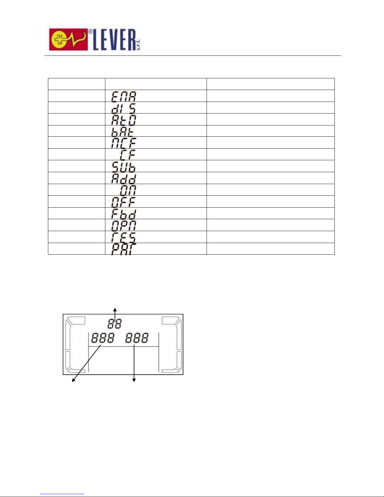
49
3-6. Significato delle abbreviazioni nel display LCD
Sigla
Contenuto display
Significato
ENA
Abilita
DIS
Disabilita
ATO
Auto
BAT
Batteria
NCF
Modalità normale (non modalità CVCF)
CF
Modalità CVCF
SUB
Sottrazione
ADD
Addizione
ON
On
OFF
Off
FBD
Non consentito
OPN
Consentito
RES
Riservato
PAR
Parallelo
3-7. Impostazione LCD
Per l'impostazione dell'UPS sono a disposizione tre parametri. Fare riferimento al diagramma seguente.
Parametro 1: Relativo alla scelta del
programma. È possibile impostare 15
programmi. Fare riferimento alla tabella sotto.
Il parametro 2 ed il parametro 3 impostano le
opzioni ed i valori per ogni programma.
Parametro 1
Parametro 2
Parametro 3
Page 51
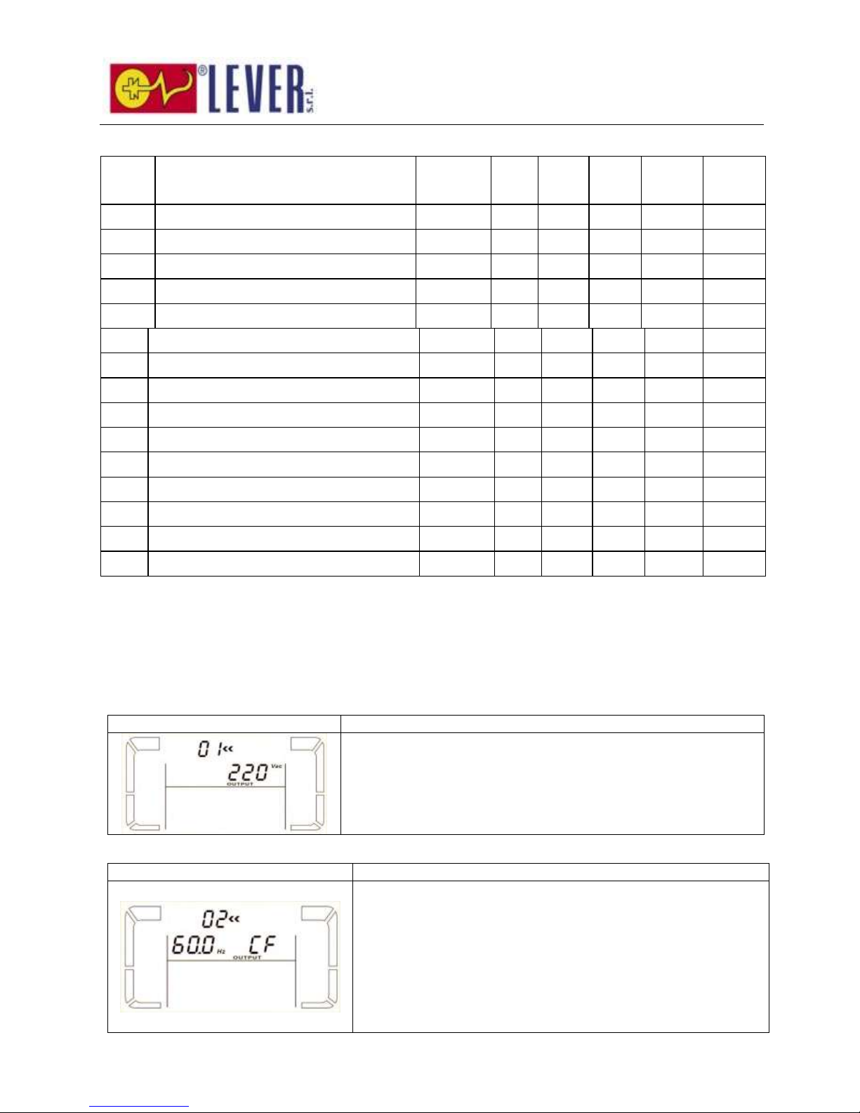
50
Elenco dei 15 programmi disponibili per il parametro 1:
Codice
Descrizione
Bypass
CA
ECO
CVCF
Batteria
Test
batteria
01
Tensione di output
Y
02
Frequenza di output
Y
03
Gamma tensione per bypass
Y
04
Gamma frequenza per bypass
Y
05
Abilita/disabilita modalità ECO
Y
06
Gamma tensione per modalità ECO
Y
07
Impostazione gamma frequenza modalità ECO
Y
08
Impostazione modalità Bypass
Y
Y
09
Impostazione tempo backup batteria
Y Y Y Y Y
Y
10
Impostazione output programmabile**
Y Y Y Y Y
Y
11
Punto arresto per output programmabile
Y Y Y Y Y
Y
12
Abilita/disabilita funzione hot standby
Y Y Y Y Y
Y
13
Regolazione tensione batteria
Y Y Y Y Y
Y
14
Regolazione tensione caricatore
Y Y Y Y Y
Y
15
Regolazione tensione output
Y
Y Y
*Y significa che questo programma può essere impostato in questa modalità.
**L'impostazione output programmabile non è supportata dai modelli Rack.
Nota: Tutte le impostazioni dei parametri saranno salvate solo quando l'UPS si spegne regolarmente con
connessione batteria interna o esterna. (Arresto UPS normale significa mettere su off l'interruttore di input in
modalità bypass).
01: Tensione di output
Interfaccia
Impostazione
Parametro 3: Tensione di output
Nel parametro 3 è possibile scegliere la seguente tensione di output:
208: tensione di output di 208Vac
220: tensione di output di 220Vac
230: tensione di output di 230Vac
240: tensione di output di 240Vac
02: Frequenza di output
Interfaccia
Impostazione
60 Hz, modalità CVCF
50 Hz, modalità Normale
Parametro 2: Frequenza di output
Impostazione della frequenza di output. Nel parametro 2 è
possibile scegliere una delle seguenti tre opzioni:
50,0Hz: La frequenza di output viene impostata a 50,0Hz.
60,0Hz: La frequenza di output viene impostata a 60,0Hz.
ATO: Se selezionato, la frequenza di output sarà decisa in base
all'ultima frequenza di rete normale. Se è da 46Hz a 54Hz, la
frequenza di output sarà 50,0Hz. Se è da 56Hz a 64Hz, la
frequenza di output sarà 60,0Hz. ATO è l'impostazione di default.
Page 52
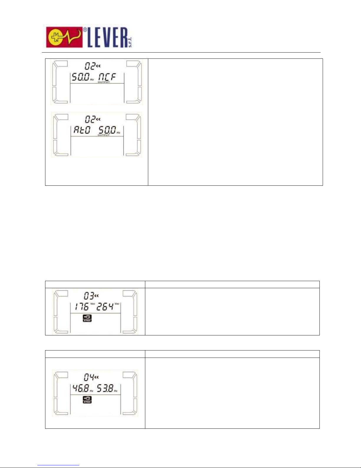
51
ATO
Parametro 3: Modalità frequenza
Impostazione della frequenza di output in modalità CVCF o meno.
Nel parametro 3 è possibile scegliere una delle seguenti due opzioni:
CF: Impostazione dell'UPS in modalità CVCF. Se selezionata, la
frequenza di output sarà fissata a 50Hz o 60Hz a seconda
dell'impostazione nel parametro 2. La frequenza di input potrebbe
essere da 46Hz a 64Hz.
NCF: Impostazione dell'UPS in modalità normale (non in modalità
CVCF). Se selezionato, la frequenza di output si sincronizzerà con
la frequenza di input tra 46 e 54 Hz a 50Hz o tra 56 e 64 Hz a 60Hz
a seconda dell'impostazione nel parametro 2. Se nel parametro 2 è
selezionato 50 Hz, l'UPS passerà in modalità Batteria quando la
frequenza di input non è compresa tra 46 e 54 Hz. Se nel
parametro 2 è selezionato 60Hz, l'UPS passerà in modalità Batteria
quando la frequenza di input non è compresa tra 56 e 64 Hz.
*Se il Parametro 2 è ATO, il Parametro 3 mostrerà la frequenza
della corrente.
Nota: Se l'UPS è impostato in modalità CVCF, la funzione bypass verrà automaticamente
disabilitata.
Ma quando un UPS singolo senza funzione parallela è alimentato dalla rete e prima che l'UPS
abbia finito l'avvio, ci saranno alcuni secondi di impulso della tensione (la stessa della tensione
in input) sull'output del bypass.
Se è necessario rimuovere l'impulso in questa modalità per proteggere meglio il proprio carico,
contattare il rivenditore. Per UPS con funzione parallela, questa situazione di impulso non si
verifica.
03: Range di tensione per bypass
Interfaccia
Impostazione
Parametro 2: Imposta la tensione minima accettabile per il
bypass. Il range di impostazione è da 110V a 209V e il valore di
default è 110V.
Parametro 3: Imposta la tensione massima accettabile per il
bypass. Il range di impostazione è da 231V a 276V e il valore di
default è 264V.
04: Range di frequenza per bypass
Interfaccia
Impostazione
Parametro 2: Imposta la frequenza minima accettabile per il
bypass.
sistema 50 Hz: Il range di impostazione è tra 46,0Hz e 49,0Hz.
sistema 60 Hz: Il range di impostazione è tra 56,0Hz e 59,0Hz.
Il valore di default è 46,0Hz/56,0Hz.
Parametro 3: Imposta la frequenza massima accettabile per il
bypass.
50 Hz: Il range di impostazione è tra 51,0Hz e 54,0 Hz.
60 Hz: Il range di impostazione è tra 61,0Hz e 64,0Hz.
Il valore di default è 54,0Hz/64,0Hz.
Page 53
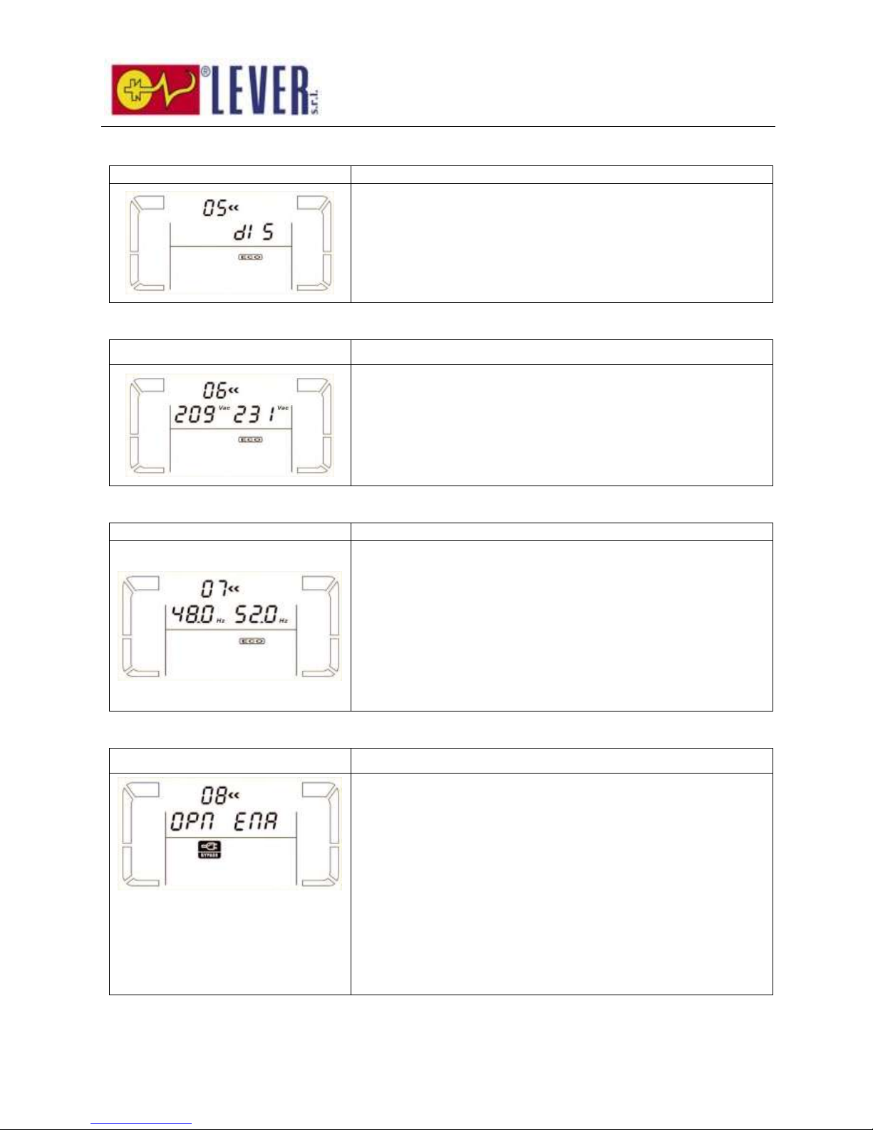
52
05: Abilita/disabilita modalità ECO
Interfaccia
Impostazione
Parametro 3: Abilita o disabilita la funzione ECO. È possibile
scegliere le seguenti due opzioni:
DIS: disabilita funzione ECO
ENA: abilita funzione ECO
Se la funzione ECO è disabilitata, il range di tensione ed il range di
frequenza per la modalità ECO possono ancora essere impostati,
ma sono ininfluenti.
06: Range di tensione per modalità ECO
Interfaccia
Impostazione
Parametro 2: Punto tensione basso in modalità ECO. Il range di
impostazione va da 5% a 10% della tensione nominale.
Parametro 3: Punto tensione alto in modalità ECO. Il range di
impostazione va da 5% a 10% della tensione nominale.
07: Range di frequenza per modalità ECO
Interfaccia
Impostazione
Parametro 2: Imposta il punto di frequenza basso per la
modalità ECO.
sistema 50 Hz: Il range di impostazione è tra 46,0Hz e 48,0Hz.
sistema 60 Hz: Il range di impostazione è tra 56,0Hz e 58,0Hz.
Il valore di default è 48,0Hz/58,0Hz.
Parametro 3: Impostazione punto frequenza alto per modalità
ECO.
50 Hz: Il range di impostazione è tra 52,0Hz e 54,0 Hz.
60 Hz: Il range di impostazione è tra 62,0Hz e 64,0Hz.
Il valore di default è 52,0Hz/62,0Hz.
08: Impostazione modalità Bypass
Interfaccia
Impostazione
Parametro 2:
OPN: Bypass consentito. Quando è selezionato, UPS opererà in
modalità Bypass a seconda dell'abilitazione o meno di bypass.
FBD: Bypass non consentito. Quando è selezionato, in nessuna
situazione è consentito operare in modalità Bypass.
Parametro 3:
ENA: Abilita Bypass. Quando è selezionato, la modalità Bypass è
attiva.
DIS: Disabilita Bypass. Quando è selezionato, il bypass
automatico è accettabile, ma il bypass manuale non è consentito.
Bypass manuale significa che gli utenti operano manualmente
l'UPS per la modalità Bypass. Ad esempio, premere il pulsante OFF
in modalità AC per passare in modalità Bypass.
Page 54
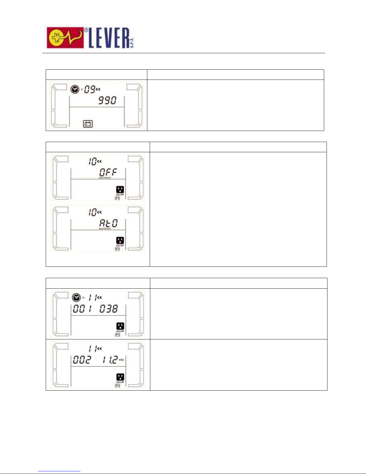
53
09: Impostazione tempo backup batteria
Interfaccia
Impostazione
Parametro 3:
000~999: Imposta il tempo di backup massimo da 0 min a 999
min. L'UPS si arresterà per proteggere la batteria dopo che il
tempo di backup si è esaurito. Il valore di default è 990 min.
DIS: Se si disabilita la protezione da scaricamento della batteria, il
tempo di backup dipenderà dalla capacità della batteria.
10: Impostazione output programmabile
Interfaccia
Impostazione
Parametro 3: Imposta l'output programmabile. È possibile
scegliere le seguenti tre opzioni:
ON: L'output programmabile viene attivato manualmente senza
limiti di tempo.
OFF: L'output programmabile viene disattivato manualmente.
Tuttavia, se l'UPS si riavvia, questa impostazione andrà
automaticamente in stato “ATO”.
ATO: L'output programmabile viene automaticamente attivato o
disattivato a seconda dello stato della batteria o del carico. Quando
la tensione della batteria è inferiore al punto di impostazione, o
arriva il tempo dell'arresto, l'output programmabile verrà
automaticamente disattivato. Dopo che la rete viene ripristinata,
l'output si attiverà automaticamente. In caso di sovraccarico, anche
l'output programmabile verrà automaticamente disabilitato. Se
questo si verifica per 3 volte, l'output programmabile verrà
disabilitato sino a che viene attivato manualmente.
11: Punto arresto per output programmabile
Interfaccia
Impostazione
Parametro 2: 001.
Imposta il tempo di arresto per l'output programmabile.
Parametro 3: Tempo di arresto in minuti.
Il range di impostazione è tra 0 e 300. Quando arriva il momento
dell'arresto, il terminale dell'output programmabile verrà
disattivato. Il valore di default è 30 minuti.
Parametro 2: 002
Imposta la tensione di arresto per l'output programmabile.
Parametro 3: Tensione di arresto in V.
Il range di impostazione è tra 11,2 e 13,6. Se la tensione della
batteria è inferiore al punto di impostazione, l'output
programmabile verrà disattivato. Il valore di default è 11,2V.
Page 55
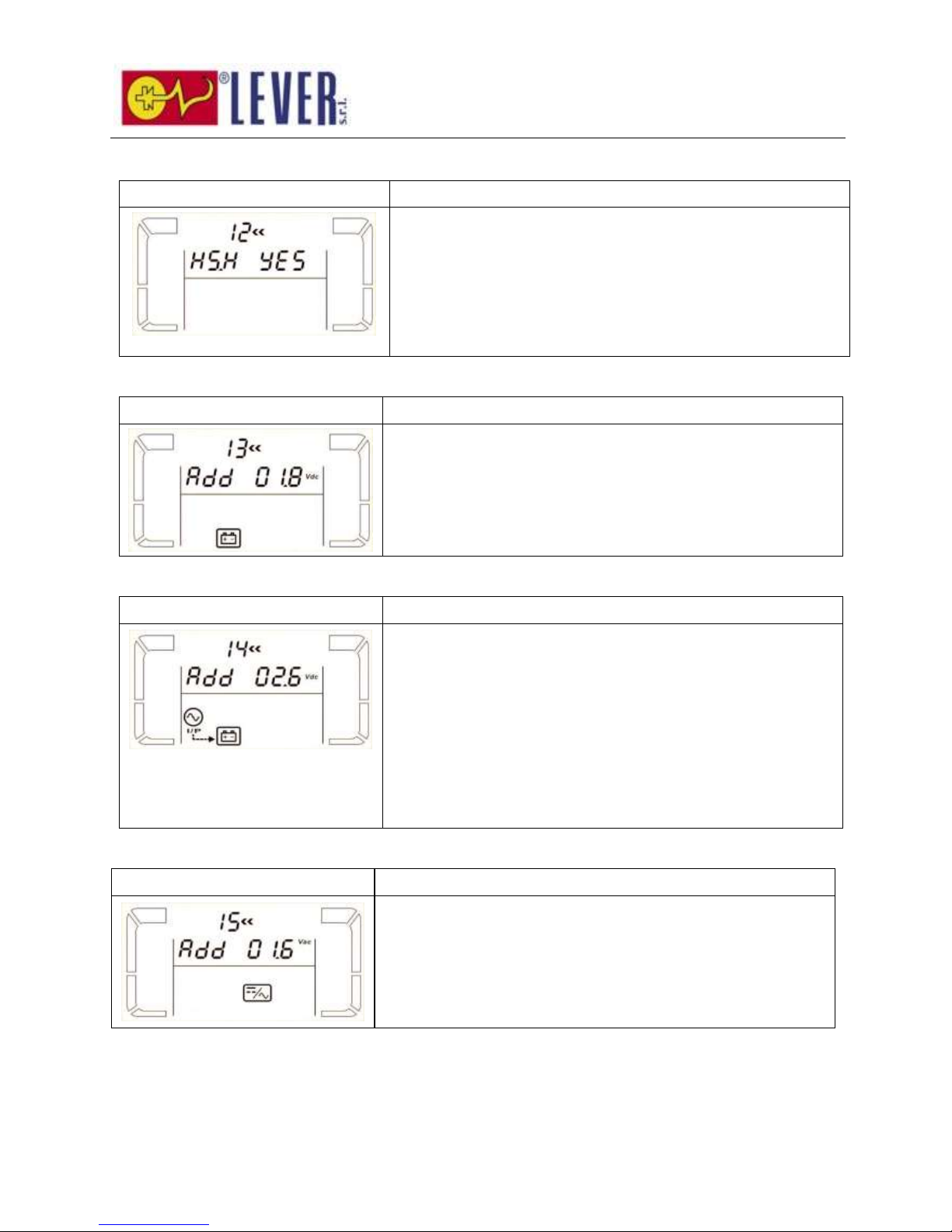
54
12: Abilita/disabilita funzione hot standby
Interfaccia
Impostazione
Parametro 2: HS.H
Abilita o disabilita la funzione Hot standby. Nel Parametro 3 è
possibile scegliere una delle seguenti due opzioni:
SÌ: La funzione Hot standby è abilitata. Significa che l'UPS
corrente è impostato come host della funzione standby, e si
riavvierà dopo il ripristino dell'AC anche senza batteria connessa.
NO: La funzione Hot standby è disabilitata. L'UPS opera in
modalità normale e non può riavviarsi senza batteria
13: Regolazione tensione batteria
Interfaccia
Impostazione
Parametro 2: Selezionare la funzione “Add” o “Sub” per
regolare la tensione della batteria sul valore effettivo.
Parametro 3: il range della tensione è da 0V a 5,7V, il valore di
default è 0V.
14: Regolazione tensione caricatore
Interfaccia
Impostazione
Parametro 2: è possibile scegliere Add o Sub per regolare la
tensione del caricatore
Parametro 3: il range della tensione è da 0V a 9,9V, il valore di
default è 0V.
NOTA:
*Prima di effettuare la regolazione della tensione, accertarsi di
scollegare prima tutte le batterie per ottenere la tensione precisa
del caricatore.
*Suggeriamo fermamente di usare il valore di default (0).
Qualsiasi modifica deve essere compatibile con le specifiche della
batteria.
15: Regolazione tensione output
Interfaccia
Impostazione
Parametro 2: è possibile scegliere Add o Sub per regolare la
tensione dell'inverter
Parametro 3: il range della tensione è da 0V a 6,4V, il valore di
default è 0V.
Page 56
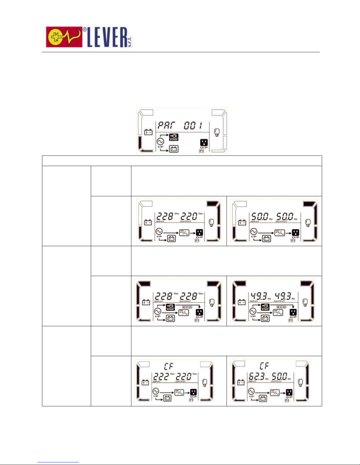
55
3-8. Descrizione modalità/stato operativo
Se i sistemi UPS paralleli sono impostati correttamente, apparirà una ulteriore schermata con “PAR” nel
parametro 2 e sarà assegnato il numero nel parametro 3 come da diagramma schermo parallelo sotto.
All'UPS verrà assegnato come default “001” ed agli UPS slave verrà assegnato “002” o “003”. I numeri
assegnati possono essere modificati dinamicamente durante l'operazione;
Modalità/stato operativo
Modalità AC
Descrizione
Quando la tensione di input è all'interno di un range accettabile, l'UPS
fornirà alimentazione AQC pura e stabile all'output. L'UPS inoltre
caricherà la batteria in modalità AC.
Display LCD
Modalità ECO
Descrizione
Quando la tensione di input è all'interno del range di regolazione della
tensione ed è attivata la modalità ECO, l'UPS bypasserà la tensione
all'output per risparmiare energia.
Display LCD
Modalità CVCF
Descrizione
Quando la frequenza di input è tra 46 Hz e 64Hz, l'UPS può essere
impostato ad una frequenza di output costante, 50 Hz o 60 Hz. In questa
modalità, l'UPS caricherà comunque la batteria.
Display LCD
Page 57
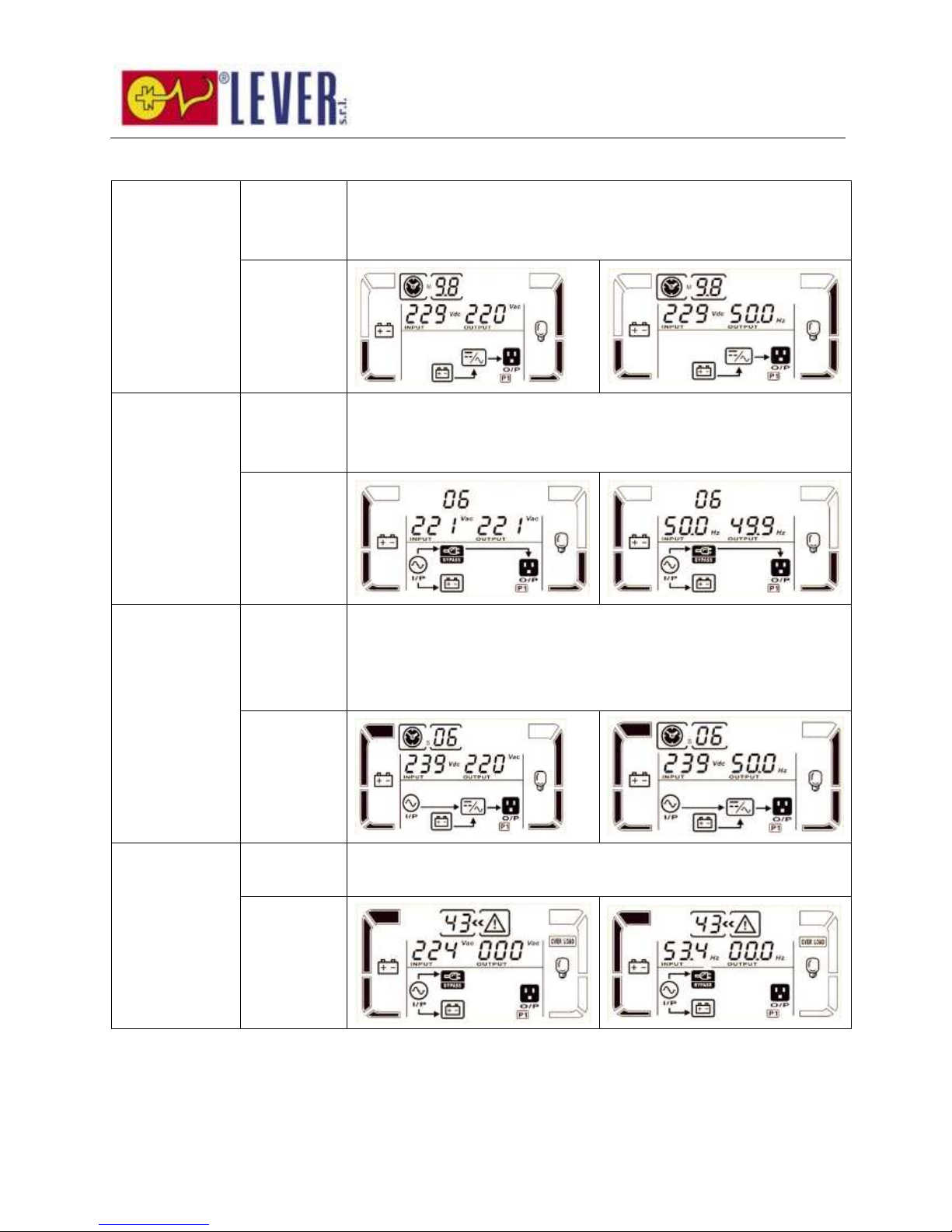
56
Modalità batteria
Descrizione
Quando la tensione di input è oltre il range accettabile o in caso di
mancanza di alimentazione, l'UPS fornirà alimentazione di backup dalla
batteria e l'allarme farà bip ogni 4 secondi.
Display LCD
Modalità Bypass
Descrizione
Quando la tensione di input è all'interno di un range accettabile ed il
bypass è abilitato, spegnendo l'UPS, entrerà in modalità Bypass.
L'allarme fa bip ogni due minuti.
Display LCD
Test di batteria
Descrizione
Quando l'UPS è in modalità AC o CVCF, premere il tasto “Test” per almeno
0,5s. L'UPS farà bip una volta e avvierà il “Test batteria”. La riga tra I/P e
le icone dell'inverter lampeggeranno per avvertire gli utenti. Questa
operazione viene utilizzata per verificare lo stato della batteria.
Display LCD
Stato di guasto
Descrizione
Quando l'UPS è in stato guasto, visualizzerà messaggi di guasto nel
pannello LCD.
Display LCD
Page 58
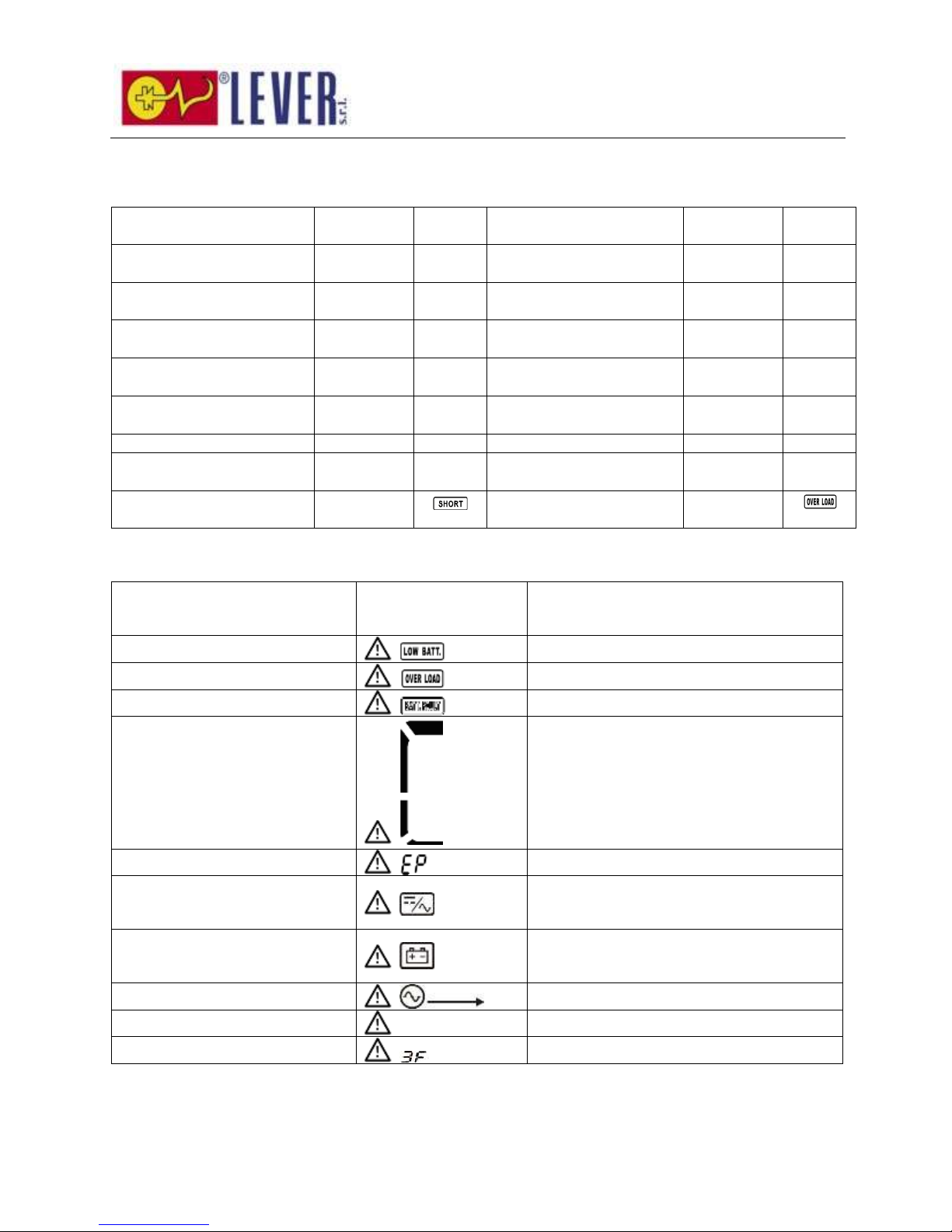
57
3-9. Codice guasto
Evento guasto
Codice
guasto
Icona
Evento guasto
Codice
guasto
Icona
Errore avvio bus
01
Nessuno
Guasto negativo
alimentazione
1A
Nessuno
Bus sopra
02
Nessuno
Batteria SCR in corto
circuito
21
Nessuno
Bus sotto
03
Nessuno
Relé inverter in corto
circuito
24
Nessuno
Sbilanciamento bus
04
Nessuno
Guasto comunicazione
parallelo
35
Nessuno
Mancato soft start inverter
11
Nessuno
Sbilanciamento corrente
output parallelo
36
Nessuno
Alta tensione inverter
12
Nessuno
Temperatura eccessiva
41
Nessuno
Bassa tensione inverter
13
Nessuno
Guasto comunicazione
CPU
42
Nessuno
Output inverter in
cortocircuito
14
Sovraccarico
43
3-10. Indicatore avviso
Avviso
Icona
(lampeggiante)
Allarme
Batteria scarica
Bip una volta al secondo
Sovraccarico
Bip due volte al secondo
Batteria non collegata
Bip una volta al secondo
Carica eccessiva
Bip una volta al secondo
Abilita EPO
Bip una volta al secondo
Guasto ventola/Temperatura
eccessiva
Bip una volta al secondo
Guasto caricatore
Bip una volta al secondo
Fusibile I/P rotto
Bip una volta al secondo
Sovraccarico 3 volte in 30min
Bip una volta al secondo
Protezione parallelo
Bip una volta al secondo
Page 59
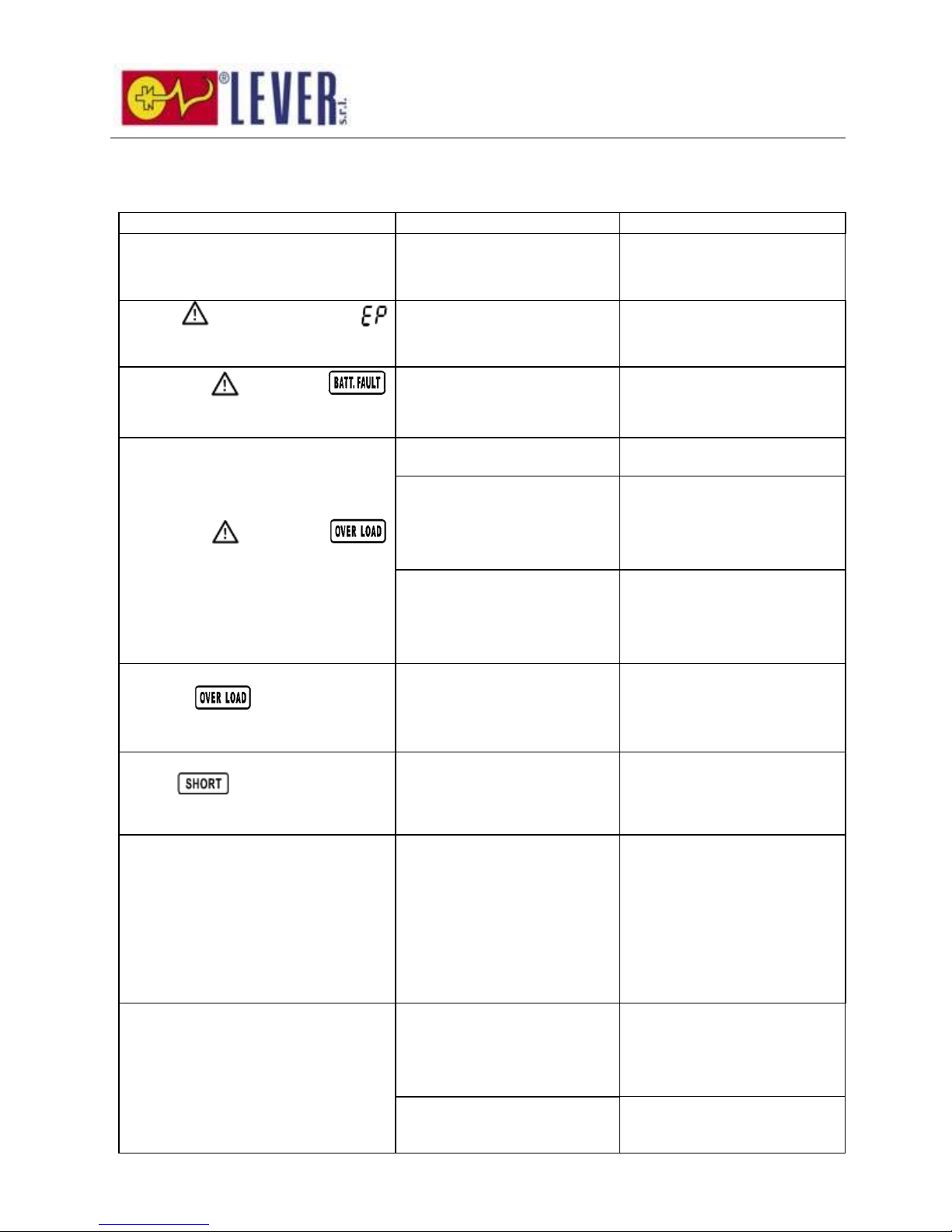
58
4. Risoluzione dei problemi
Se il sistema UPS non funziona correttamente, risolvere il problema usando la tabella seguente.
Sintomo
Possibile causa
Rimedio
Nessuna indicazione e allarme sul
display anteriore anche se la rete è
normale.
L'alimentazione AC in ingresso
non è collegata correttamente.
Verificare se il cavo elettrico in
ingresso è collegato
saldamente alla rete.
L'icona ed il codice avviso
lampeggiano sul display LCD e
l'allarme fa bip ogni secondo.
La funzione EPO è abilitata.
Impostare il circuito in
posizione chiusa per
disabilitare la funzione EPO.
L'icona e
lampeggiano sul display LCD e
l'allarme fa bip una volta ogni secondo.
La batteria esterna o interna è
connessa in modo non
corretto.
Verificare se le batterie sono
connesse correttamente.
L'icona e
lampeggiano sul display LCD e
l'allarme fa bip due volte al secondo.
L'UPS è sovraccarico.
Rimuovere i carichi in eccesso
dall'output dell'UPS.
L'UPS è sovraccarico. I
dispositivi connessi all'UPS
sono alimentati direttamente
dalla rete elettrica tramite
Bypass.
Rimuovere i carichi in eccesso
dall'output dell'UPS.
Dopo sovraccarichi ripetuti,
l'UPS si blocca in modalità
Bypass. I dispositivi connessi
sono alimentati direttamente
dalla rete.
Per prima cosa rimuovere i
carichi in eccesso dall'output
dell'UPS. Quindi spegnere e
riaccendere l'UPS.
Il codice guasto visualizzato è 43.
L'icona si illumina sul
display LCD e l'allarme fa bip in modo
continuo.
L'UPS è sovraccarico da troppo
tempo e va in guasto. Quindi
l'UPS si arresta
automaticamente.
Rimuovere i carichi in eccesso
dall'output dell'UPS e
riavviarlo.
Il codice guasto visualizzato è 14.
l'icona lampeggia sul display
LCD e l'allarme fa bip in modo
continuo.
L'UPS si è spento
automaticamente a causa di
un cortocircuito presso l'output
dell'UPS.
Controllare il cablaggio in
output e se i dispositivi
connessi sono in stato di
cortocircuito.
I codici guasto 1, 2, 3, 4, 11, 12, 13,
14,1A, 21, 24, 35, 36, 41, 42 o 43
vengono visualizzati sul display LCD e
l'allarme fa bip in modo continuo.
Si è verificato un guasto
interno dell'UPS. Ci sono due
possibili risultati:
1. Il carico viene ancora
fornito, ma direttamente
dall'alimentazione AC tramite
bypass.
2. Il carico non viene più
fornito dall'alimentazione.
Contattare il proprio
rivenditore.
Il tempo di backup della batteria è
inferiore al valore nominale
Le batterie non sono
completamente cariche
Caricare le batterie per almeno
7 ore e quindi verificare la
capacità. Se il problema
persiste, consultare il proprio
rivenditore.
Difetto delle batterie
Contattare il proprio
rivenditore per sostituire la
batteria.
Page 60
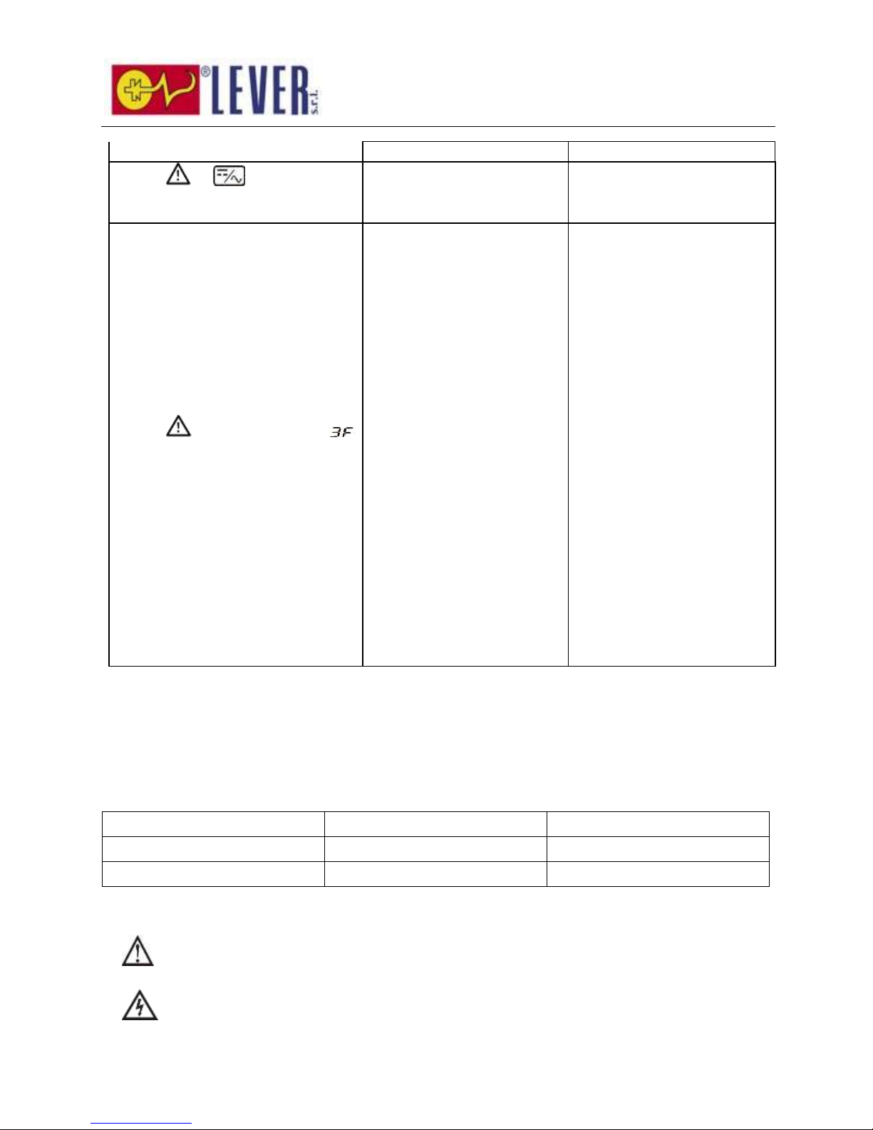
59
Sintomo
Possibile causa
Rimedio
L'icona e lampeggiano sul
display LCD e l'allarme fa bip una volta
ogni secondo.
La ventola è bloccata o non
funziona; o la temperatura
dell'UPS è troppo elevata.
Controllare le ventole e
contattare il rivenditore.
L'icona ed il codice avviso
lampeggiano sul display LCD e
l'allarme fa bip ogni secondo.
Cavo comunicazione parallelo
non stretto o funzionamento
parallelo non corretto.
Per un sistema parallelo,
accertarsi che il cavo di
comunicazione parallelo sia
connesso strettamente e
verificare anche se il numero
PRA ID è corretto dopo aver
messo su on gli interruttori di
input uno ad uno. Se tutti i
numeri visualizzati sono
corretti, è ok accendere gli UPS
dopo aver disabilitato il
messaggio di avviso premendo
contemporaneamente i tasti
‘SU’ e ‘GIÙ’. Altrimenti, NON
accendere gli UPS e contattare
il proprio rivenditore.
In caso di UPS singolo, poiché
non vi è connessione di cavo di
comunicazione e cavo di
output parallelo,
semplicemente ignorare
questo messaggio di avviso
premendo il pulsante ‘UP’ e
‘DOWN’ per disabilitare ed
accendere l'UPS per
funzionamento continuo.
5. Stoccaggio e manutenzione
5-1. Stoccaggio
Prima dello stoccaggio, caricare l'UPS per almeno 7 ore. Stoccare l'UPS coperto ed in posizione eretta in
un luogo fresco e secco. Durante lo stoccaggio, ricaricare la batteria secondo la seguente tabella:
Temperatura di stoccaggio
Frequenza di ricarica
Durata della ricarica
-25°C - 40°C
Ogni 3 mesi
1-2 ore
40°C - 45°C
Ogni 2 mesi
1-2 ore
5-2. Manutenzione
Il sistema UPS opera con tensioni pericolose. Le riparazioni possono essere effettuate solo da
personale di manutenzione qualificato.
Anche dopo che l'unità è stata scollegata dalla rete, i componenti all'interno del sistema UPS sono
ancora connessi ai pacchi batterie, che sono potenzialmente pericolosi.
Page 61
60
Prima di effettuare qualsiasi intervento e/o manutenzione, scollegare le batterie e verificare che
nessuna corrente sia presente e che non esista nessuna tensione pericolosa nei terminali dei condensatori
ad alta capacità come i condensatori BUS.
Solo persone con adeguata familiarità con batterie e con le misure di cautela richieste possono
sostituire le batterie e supervisionare le operazioni. Le persone non autorizzate non devono avvicinarsi alle
batterie.
Verificare che non sia presente alcuna tensione tra i terminali della batteria e la terra prima della
manutenzione o della riparazione. In questo prodotto, il circuito della batteria non è isolato dalla tensione
di input. Si possono verificare tensioni pericolose tra i terminali della batteria e la terra.
Le batterie possono causare shock elettrico ed avere un'elevata corrente di cortocircuito. Rimuovere
orologi da polso, anelli e altri oggetti metallici personali prima della manutenzione o della riparazione, ed
usare solo strumenti con impugnature isolate per la manutenzione e la riparazione.
Quando si sostituiscono le batterie, installare lo stesso numero e lo stesso tipo di batterie.
Non cercare di smaltire le batterie bruciandole. Questo potrebbe causare l'esplosione della batteria.
È necessario smaltire le batterie correttamente in base alle norme locali.
Non aprire o distruggere le batterie. La fuoriuscita di elettrolito può causare lesione alla pelle ed agli
occhi. Può essere tossico.
Quando si sostituisce un fusibile, usarne uno dello stesso tipo e con lo stesso amperaggio, per
evitare pericoli di incendio.
Non smontare il sistema UPS.
Page 62

61
6. Specifiche
MODELLO
6K
10K
CAPACITÀ*
6000 VA / 5400 W
10000 VA / 9000 W
INPUT
Range
di
tensione
Perdita linea bassa
110 VAC ± 3 % a 50% di carico; 176 VAC ± 3 % a 100% di carico
Ritorno linea bassa
Perdita linea bassa tensione + 10V
Perdita linea alta
300 VAC ± 3 %
Ritorno linea alta
Perdita linea alta tensione - 10V
Gamma di frequenza
da 46Hz a 54 Hz @ sistema 50Hz
da 56Hz a 64 Hz @ sistema 60Hz
Fase
Fase singola con terra
Fattore potenza
≧ 0,99 a 100% di carico
OUTPUT
Tensione di output
208/220/230/240VAC
Regolazione tensione AC
± 1%
Gamma di frequenza
(Range sincronizzato)
da 46Hz a 54 Hz @ sistema 50Hz
da 56Hz a 64 Hz @ sistema 60Hz
Range frequenza (Modalità
batteria)
50 Hz ± 0.1 Hz o 60Hz ± 0.1 Hz
Sovraccarico
Modalità AC
da 100% a 110%: 10min、da 110% a 130%: 1min、>130% : 1sec
Modalità batteria
da 100% a 110%: 30sec、da 110% a 130%: 10sec、>130% : 1sec
Fattore di cresta della corrente
3:1 max
Distorsione armonica
≦ 3 % @ 100% carico lineare; ≦ 6 % @ 100% carico non lineare
Tempo di
trasferimento
Linea Batt
eria
0 ms
Inverter By
pass
0 ms
Inverter E
CO
<10 ms
EFFICIENZA
Modalità AC
> 89%
Modalità batteria
> 88%
BATTERIA
Modello
standard
Tipo & Numeri
12 V / 7 Ah x 20
12 V / 9 Ah x 20
Tempo di ricarica
7 ore ripristinano il 90% della capacità
9 ore ripristinano il 90% della capacità
Corrente di carica
1 A ± 10% (max.)
1 A ± 10% (max.)
Tensione di carica
273 V ± 1%
Modello a
lunga
autonomia
Tipo
A seconda delle applicazioni
Numeri
18 - 20
Corrente di carica
4 A ± 10% (max.)
4 A ± 10% (max.)
Tensione di carica
273 V ± 1%
CARATTERISTICHE FISICHE
Modello
standard
Dimensione,
PXLXA(mm)
592 X 250 X 576
592 X 250 X 576
Peso netto (kg)
81
83
Modello a
lunga
autonomia
Dimensione,
PXLXA(mm)
592 X 250 X 576
592 X 250 X 576
Peso netto (kg)
25
27
AMBIENTE
Temperatura operativa
da 0 a 40°C (l'autonomia della batteria si ridurrà quando > 25°C)
Umidità operativa
<95 % e non-condensante
Altitudine operativa**
<1000m
Livello rumore acustico
Inferiore a 55dB ad 1 Metro
Inferiore a 58dB ad 1 Metro
GESTIONE
Smart RS-232 o USB
Supporta Windows® 2000/2003/XP/Vista/2008/7/8, Linux, Unix, e MAC
SNMP opzionale
Gestione alimentazione da SNMP manager e browser web
* Capacità di declassamento al 60% della capacità in modalità CVCF ed a 90% quando la tensione di output è regolata a 208VAC.
** Se l'UPS è installato o utilizzato in un luogo dove l'altitudine è superiore a 1000m, la potenza di output deve essere declassata dell'1% per
Page 63

62
ogni 100m.
*** Le specifiche del prodotto sono soggette a modifiche senza preavviso.
Power solutions since 1973
LEVER SRL
Via Del Lavoro, 17
37020 Arbizzano (VR) – Italy
Tel. +39 045 6020162
Fax. +39 045 6020147
Email: [email protected]
Website: www.lever.it
Revision History
Rev.
Date
Description
Cod. N°
00
27 March 2014
First Issues
0200276700
EC1000 Series 6-10kVA User Manual rev.1- Specifications subject to change without prior notice.
The company reserves the right to modify the specifications given without notice.
 Loading...