

Page 1

Contents
Help Manual
Help Manual ......................................................... 1
1 How to start? ................................................. 1
1.1 Start ............................................. 1
1.2 Create the camera Video window ..................... 1
2 Video window GUI .............................................. 2
2.1 Video window GUI .................................. 2
2.2 How to close the Video window? ..................... 3
3 Image window GUI .............................................. 4
3.1 Image window GUI .................................. 4
3.2 How to close the Image window? ..................... 5
4 UI toolbar .................................................... 7
5 Camera sidebar ................................................ 8
5.1 Capture & Resolution group ......................... 8
5.2 Exposure & Gain group ............................. 8
5.3 White Balance group ............................... 8
5.4 Color Adjustment group............................. 9
5.5 Frame Rate group .................................. 9
5.6 Flip group ........................................ 9
5.7 Color/Gray group .................................. 9
5.8 Power Frequency group ............................. 9
5.9 Sampling group ................................... 10
5.10 Histogram group .................................. 10
6 File......................................................... 11
6.1 Open Image••• Ctrl+O .......................... 11
6.2 Open Video••• ................................. 13
6.3 Camera List ...................................... 14
6.4 Twain: Select Device•••........................... 14
6.5 Twain:Acquire••• ................................. 15
6.6 Save Ctrl+S ................................... 16
1
Page 2
Contents
6.7 Save As••• ....................................... 17
6.8 Batch Save••• .................................... 21
6.9 Paste as New File••• ............................. 22
6.10 Print Setup••• ................................... 22
6.11 Print Preview••• Ctrl+Shift+P ..................... 23
6.12 Print••• Ctrl+P .................................. 23
6.13 Recent Files ..................................... 23
6.14 Exit ............................................. 24
7 Edit......................................................... 25
7.1 Undo/Redo Ctrl+Z ................................. 25
7.2 Forward .......................................... 25
7.3 Backward ......................................... 26
7.4 Cut Ctrl+X ....................................... 28
7.5 Copy Ctrl+C ...................................... 28
7.6 Paste Ctrl+V ..................................... 30
7.7 Image Select ................................ 30
7.8 Select All Ctrl+A ................................ 31
7.8.1 Select All on the Background layer ................ 31
7.8.2 Select All objects over the Background layer ...... 31
7.9 Select None Ctrl+D ............................... 31
7.10 Inverse Selection ................................ 31
7.11 Delete File Delete ............................... 32
8 View......................................................... 33
8.1 Browse Ctrl+B ................................. 33
8.1.1 Open the Browse window............................ 33
8.1.2 Browse window right mouse button context menu ..... 33
8.2 Sort>Sort by Names ............................... 34
8.3 Sort>Sort by Type ................................ 34
8.4 Sort>Sort by Size ................................ 34
8.5 Sort>Sort by Width ............................... 34
8.6 Sort>Sort by Height .............................. 34
8.7 Sort>Forward ..................................... 34
2
Page 3

Contents
8.8 Sort>Reverse ..................................... 35
8.9 Icon>Large Icons ................................. 35
8.10 Icon>Small Icons ................................. 35
8.11 Refresh F5 ....................................... 35
8.12 Measurement Sheet ................................ 36
8.12.1 File Import••• ................................... 36
8.12.2 File Save••• ..................................... 36
8.12.3 Export>To Html File .............................. 36
8.12.4 Export to Excel .................................. 36
8.12.5 Auto Highlight ................................... 37
8.12.6 Settings••• ...................................... 37
8.13 Sidebar .......................................... 38
8.13.1 Sidebar overview ................................. 38
8.13.2 Sidebar>Camera ................................... 39
8.13.3 Sidebar>Folder ................................... 39
8.13.4 Sidebar>Undo/Redo ................................ 40
8.13.5 Sidebar>Layer .................................... 40
8.13.6 Sidebar>Measurement .............................. 40
8.14 Ruler and Grid ................................... 40
8.14.1 Grids>No Grids ................................... 40
8.14.2 Grids>Manual Grids ............................... 40
8.14.3 Grids>Auto Grids ................................. 41
8.14.4 Grids>Remove All Grids............................ 42
8.14.5 Settings••• ...................................... 42
8.15 Best Fit ......................................... 42
8.16 Actual Size ...................................... 42
8.17 Track ......................................... 42
8.18 Properties ....................................... 43
9 Setup ........................................................ 45
9.1 Start/Pause ...................................... 45
9.2 Full Screen ...................................... 45
9.3 View Properties••• ............................... 45
3
Page 4

Contents
9.4 Video Overlay••• ................................. 46
9.4.1 Video Overlay: Overlay............................ 46
9.4.2 Video Overlay: Marker••• .......................... 47
9.5 Video Watermark••• ............................... 48
9.6 Move Watermark ................................... 50
9.6.1 Move to••• ....................................... 50
9.6.2 Move to zero ..................................... 50
9.7 Rotate Watermark ................................. 50
9.7.1 Rotate to••• ..................................... 50
9.7.2 Rotate to zero ................................... 51
9.8 Gray Calibration••• .............................. 51
9.9 Manual Fusion••• .............................. 52
9.10 Video Source Property••• .......................... 53
9.11 Video Stream Format•••............................ 53
9.12 Still Image Options•••............................ 54
10 Capture ...................................................... 56
10.1 Capture Image F8 ................................. 56
10.2 Time-lapse (Auto Capture)••• ...................... 56
10.3 Start Record••• F9 ............................... 57
11 Image ........................................................ 61
11.1 Mode ............................................. 61
11.1.1 Color Quantize••• ................................ 61
11.1.2 Gray Scale ....................................... 61
11.2 Adjust ........................................... 61
11.2.1 Curve••• ......................................... 61
11.2.2 Auto Level ....................................... 62
11.2.3 Auto Contrast .................................... 63
11.2.4 Histogram Equalization............................ 63
11.2.5 Brightness/Contrast•••............................ 64
11.2.6 Color••• ......................................... 64
11.2.7 HMS••• ........................................... 66
11.2.8 Gamma••• ......................................... 67
4
Page 5

Contents
11.2.9 Filter Color••• .................................. 67
11.2.10 Extract Color••• ................................. 67
11.2.11 Invert ........................................... 68
11.3 Rotate ........................................... 68
11.3.1 90(CW) ........................................... 68
11.3.2 180(CW) .......................................... 68
11.3.3 270(CW) .......................................... 68
11.3.4 Arbitrary••• ..................................... 68
11.3.5 Flip Horizontal .................................. 69
11.3.6 Flip Vertical .................................... 69
11.4 Crop Shift+C ..................................... 69
11.5 Image Scale••• ................................... 70
11.6 Histogram••• ..................................... 71
11.7 Resolution••• .................................... 73
11.8 Overlay Scale Bar••• ............................. 73
12 Process ...................................................... 75
12.1 Filter••• Shift+F ................................ 75
12.1.1 Image Enhance .................................... 75
12.1.2 Edge Enhance ..................................... 78
12.1.3 Morphological .................................... 79
12.1.4 Kernel ........................................... 82
12.2 Range••• Shift+R ................................. 84
12.3 Segmentation••• Shift+S .......................... 84
12.4 Binary••• Shift+B ............................... 85
12.5 Emboss••• Shift+E ................................ 86
12.6 Pseudo Color••• .................................. 86
12.7 Surface Plot••• .................................. 87
12.8 Line Profile••• .................................. 88
12.9 Diffuse••• Shift+D ............................... 89
12.10 Granulate••• Shift+G ............................. 89
12.11 Mosaic••• ........................................ 89
12.12 Fusion••• ........................................ 91
5
Page 6
Contents
12.13 Color Composite••• ............................... 93
13 Layer ........................................................ 99
13.1 About Layer ...................................... 99
13.2 Organizing layers ................................ 99
13.3 Layers for non-destructive measurement and label .. 99
13.4 Layer sidebar .................................... 99
13.5 Layer menu and layer sidebar page context menu ... 100
13.6 New••• .......................................... 101
13.7 Remove••• ....................................... 101
13.8 Current••• ...................................... 101
13.9 Show/Hide••• .................................... 101
13.10 Rename••• ....................................... 101
13.11 Export to Image ................................. 101
13.12 Export to Microsoft Excel ........................ 101
14 Measurements ................................................ 102
14.1 Object Select ................................ 102
14.2 Angle ........................................ 103
14.3 Point ........................................ 104
14.4 Line ............................................ 104
14.4.1 Line>Arbitrary Line .......................... 104
14.4.2 Line> Horizontal Line ........................ 105
14.4.3 Line> Vertical Line ........................... 105
14.5 Parallel ..................................... 106
14.6 Vertical .................................... 107
14.6.1 Vertical>Four Points. ......................... 107
14.6.2 Vertical>Three Points ....................... 107
14.7 Rectangle .................................... 108
14.8 RoundRect .................................... 109
14.9 Ellipse ...................................... 109
14.10 Circle ...................................... 110
14.10.1 Circle>Center+Radius ......................... 110
14.10.2 Circle>Two Points ............................. 111
6
Page 7
Contents
14.10.3 Circle>Three Points .......................... 111
14.11 Annulus ...................................... 111
14.12 Two Circles .................................. 112
14.12.1 Two Circle>Center+Radius ......................... 112
14.12.2 Two Circle>Three Points.......................... 112
14.13 Arc .......................................... 113
14.14 Text ......................................... 113
14.15 Polygon ...................................... 114
14.16 Z Order ......................................... 115
15 Options ..................................................... 116
15.1 Preferences••• .................................. 116
15.1.1 File ............................................ 116
15.1.2 Plugin .......................................... 116
15.1.3 Print ........................................... 117
15.1.4 Rulers and Grids ................................ 118
15.1.5 Cursor .......................................... 119
15.1.6 Capture ......................................... 120
15.1.7 Misc ............................................ 121
15.2 Measurements••• ................................. 121
15.2.1 General>General ................................. 122
15.2.2 General>Length Unit ............................. 122
15.2.3 General>Angle Unit .............................. 124
15.2.4 General>Measurement Sheet ........................ 124
15.2.5 Object>Point .................................... 125
15.2.6 Object>Line ..................................... 126
15.2.7 Object>Other Objects ............................ 126
15.2.8 Magnifications••• ............................... 126
15.3 Calibrate••• ................................. 127
15.4 Edit Dye List••• ................................ 130
15.5 Auto Correction••• .............................. 132
16 Windows ..................................................... 133
16.1 Close All ....................................... 133
7
Page 8

Contents
16.2 Windows••• ...................................... 134
17 Help........................................................ 135
17.1 Help Contents ................................... 135
17.2 About ........................................... 135
8
Page 9
Help Manual
1 How to start?
1.1 Start
1. Double click on the desktop icon “ ”, and start ToupView;
2. Click Start button (At your screen bottom left corner) and a Start menu will bring
up. Move your mouse point over the menu and try to locate ToupView, click to start.
1.2 Create the camera Video window
ToupView will detect all of the cameras that your computer has installed (Here, it is
UCMOS03100KPA, a 3.1M pixel CMOS camera) and will append all the camera names
as submenu to File>Camera List menu (Here, the submenu name is
“UCMOS03100KPA”).
Choosing File>Camera List> UCMOS03100KPA will create a Video window and begin
to start the Video stream. Your Video window will be associated with the name of
“Video [UCMOS03100KPA]” (i.e., its title bar will display “Video
[UCMOS03100KPA]”).
There are 3 methods to start the camera Video stream, they are:
1. Choose File>Camera List>UCMOS03100KPA (Here, a 3.1M pixel camera is
installed) command to create the camera Video window;
2. Click Camera bar (If it is not activated) and Camera List to expand the Camera List
group (if not expanded). Click the camera name (Here it is UCMOS03100KPA) to
create the Video window;
3. Click the ’s down arrow to expand the camera list and choose the right camera
(Here it is UCMOS03100KPA) to create the Video window.
1
Page 10
2 Video window GUI
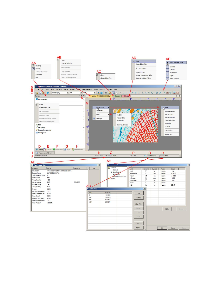
2.1 Video window GUI
Help Manual
A:ToupView; B: Menu; C:ToupView toolbar D:Camera sidebar;
E: Folders sidebar; F: Undo/Redo sidebar; G: Layer sidebar;
H: Measurement sidebar; I: Measurement Sheet; J:Status bar;
2
Page 11

Help Manual
K: Auto Hide button L: Horizontal ruler; M:Vertical ruler
N:Frame Rate O:Frames captured P:Current Video sizes
Q:Selected microscope Magnification R:Current Unit;
AA: Sidebar right mouse button context menu;
AB: Video window right mouse button context menu;
AC: Browse window right mouse button context menu;
AD: Image window right mouse button context menu;
AE: Frame window right mouse button context menu;
AF: Double-click bring up Video Properties dialog;
AG: Double-click bring up Magnification dialog;
AH: Double-click bring up Measurement dialog;
AI: Horizontal Ruler or Vertical Ruler right mouse button context menu
2.2 How to close the Video window?
1) Double-clicking the tabbed Video window title or clicking x on will close the
Video window directly;
2) For MDI Video window, click x on to close the Video window;
3). Choose Windows>Close All command to close the Video window.
3
Page 12
3 Image window GUI
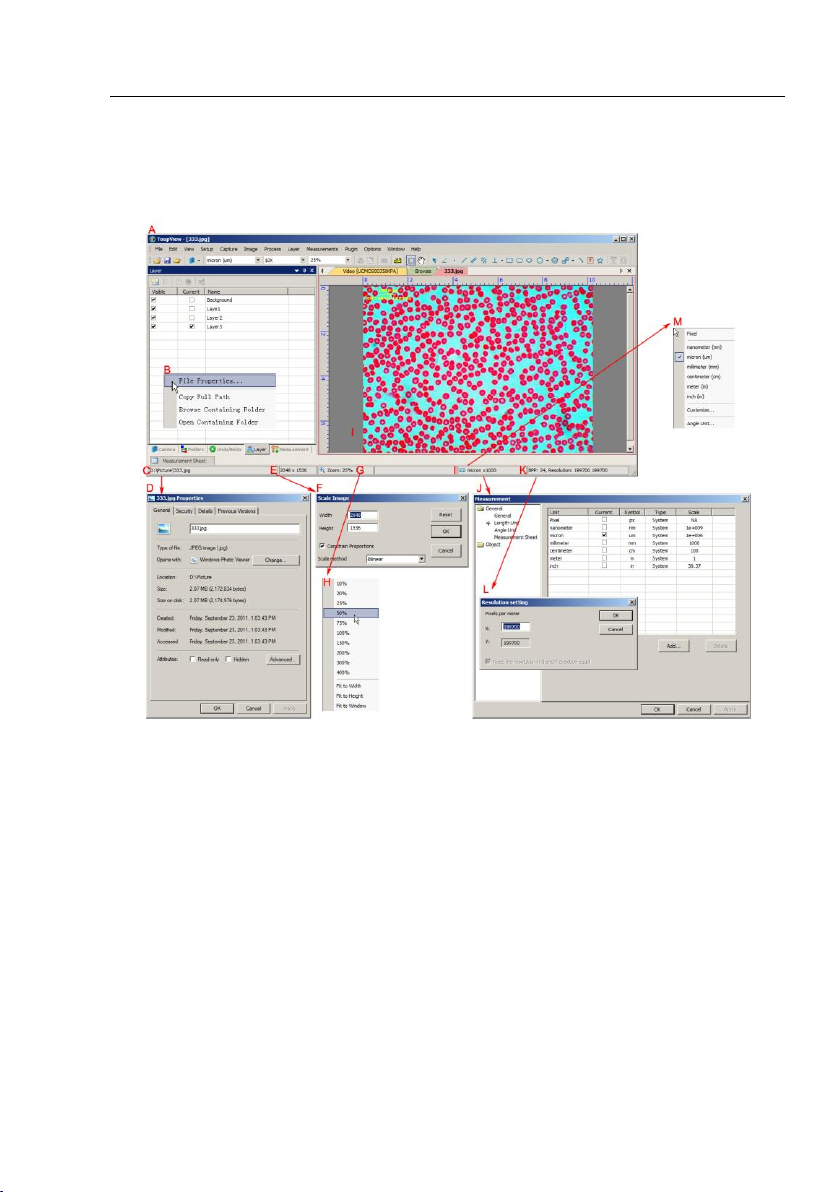
3.1 Image window GUI
Help Manual
A:ToupView; B: Opened file right mouse button context menu on status bar;
C:Opened file name and directory;
D: Double-click bring up opened file Properties dialog;
E: Image size in the both directions;
F: Double-click bring up Scale Image dialog;
G: Image Zoom ratio, double-clicking will zoom the image to 100%;
H: Zoom ratio right mouse button context menu;
I: Currently selected Unit J: Double-click bring up Measurement dialog;
K: Image BPP & Resolution;
L: Double-click bring up Resolution Setting dialog;
M: Unit right mouse button context menu.
4
Page 13
Help Manual
3.2 How to close the Image window?
1. Tabbed window
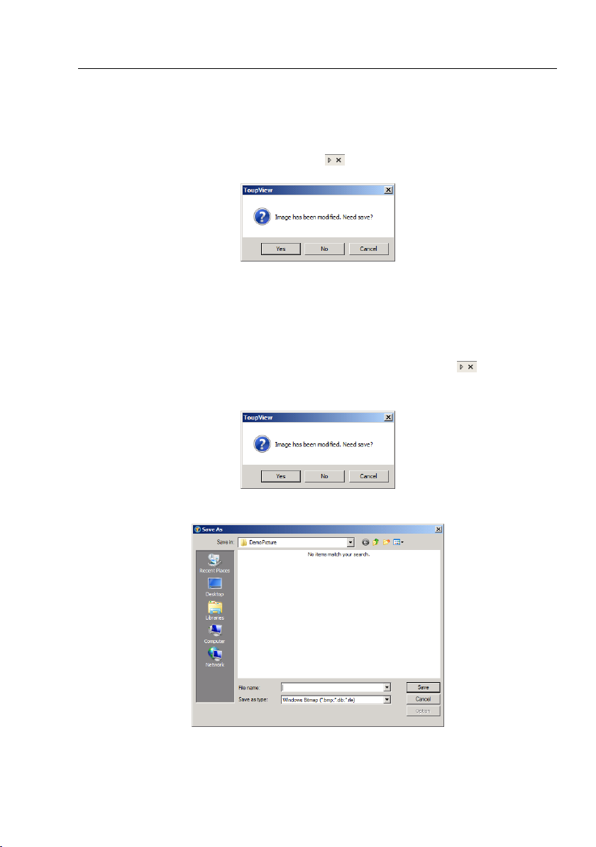
a) If you have modified an image before attempting to close it, double-clicking the
tabbed Image window title or clicking x on will bring up a warning dialog:
Clicking Yes will save the changes with its old name and close the window quickly, No
will close the file immediately with no changes and no warning, or Cancel will cancel
the Close command and leave the window there with no changes;
b) If the Image window is snapped from the Video window and with number as its
title, double-clicking the tabbed Image window title or clicking x on will bring up
a warning ToupView dialog:
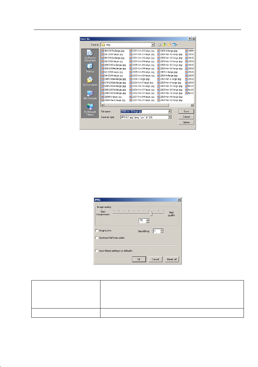
Clicking Yes will bring up a Save As dialog:
Select the driver and folder to which you want your image file saved in the Save in list
5
Page 14
Help Manual
box and enter the file name in the File name edit box.
Click Save to save the captured image with the specified directory and file name, or
Cancel to close the Save As dialog and return to Image window.
Clicking No on the ToupView dialog will close the file immediately with no changes
and no warning or Cancel on the ToupView dialog will cancel the Close command and
return to Image window.
Note: 3). Choosing Windows>Close All command can also close the tabbed Image
window. Check Windows>Close All for detail.
2. MDI window
a) For an opened and modified Image window, click x on to bring up the same
ToupView dialog. The next operations are just the same as the tabbed window in step
1a;
b). For a Video captured image with number as its title, click x on to bring up
the same ToupView dialog. The next operations are just the same as the tabbed
window, step 1b.
Note: Choosing Windows>Close All command can also close the MDI Image window.
Check Windows>Close All for detail.
6
Page 15
Help Manual
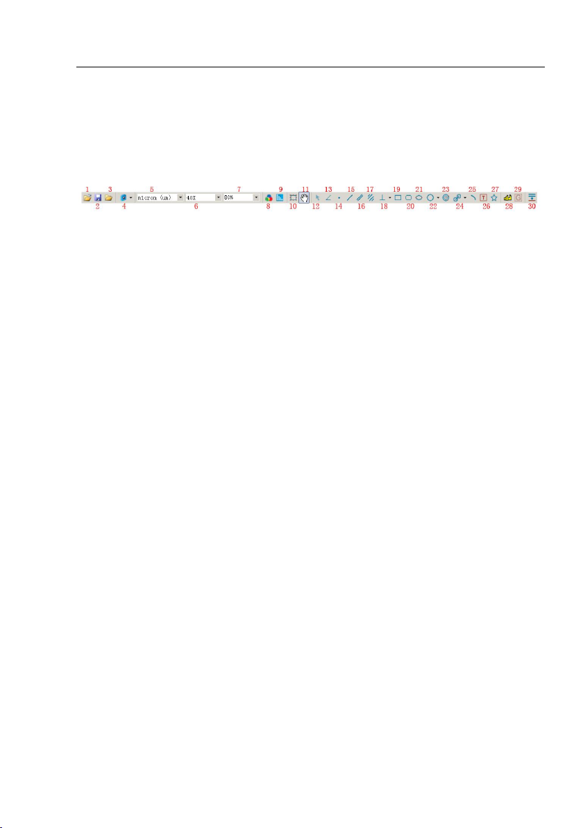
4 UI toolbar
When the camera is started or the image is opened, most of the icons on the toolbar
will be available for the quick setup of the Video or Image characteristic.
1: Open (Ctrl + O) 2: Save (Ctrl + S) 3: Browse (Ctrl + B)
4: Camera List 5: Unit 6: Magnification 7: Zoom
8: Video Source Properties(will be enabled only for the camera that support
directshow interface)
9: Video Stream Format(will be enabled only for the camera that support directshow
interface)
10:Video/Image Select
11: Track(enabled only when the video/image sizes large than the window size)
12: Object Select(will be enabled only when an object is existed on the layer above
the background layer) 13: Angle 14: Point 15: Line
16: Parallel 17: Two Parallel 18: Vertical 19: Rectangle
20 RoundRect 21: Ellipse 22: Circle 23:Annulus
24: Two Circles 25: Arc 26: Text 27: Polygon
28: Calibration (for both video/image window)
29:Gray Calibration (will be enabled only when a rectangle area is selected)
30: Manual Fusion.
7
Page 16
Help Manual
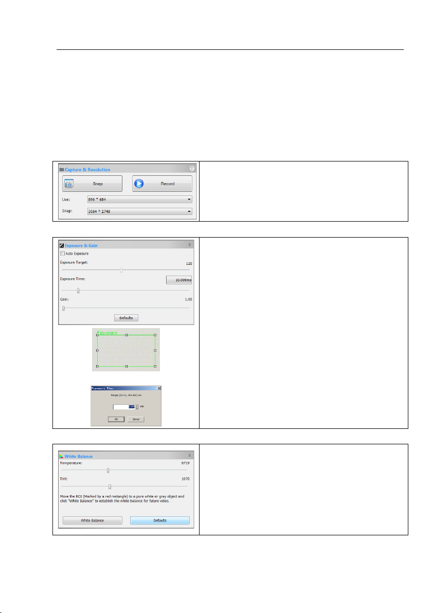
Snap: Continuously Snap images by clicking it;
Record: Record Video stream in wmv/asf or avi format;
Live: Set the Video resolution;
Snap: Set the Snap resolution for use in the image capture process.
Overlaid Rectangle for Exposure
1. When the Exposure & Gain group is expanded,a green rectangle viewfinder
marked with “Exposure” will be overlaid on the Video. This labeled region is
taken as reference region for judging if the image brightness is reached to the
Exposure Target value. Drag the Exposure ROI to the dark area will increase
the image brightness and drag it to brighter area will decrease the image
brightness;
2. Uncheck the Auto Exposure box to switch the Auto Exposure mode to
Manual Exposure. The Exposure Target slider will be disabled in this mode;
3. Tune the microscope light source to a bright state, and then drag Exposure
Time slider left or right until the image brightness is normal;
4. If and only if the microscope light intensity is too low to meet the imaging
requirement, drag the Gain slide right until the image brightness is normal;
5. The exact Exposure Time can also be entered by clicking the edit box at the
right of the Exposure Time: label. This will bring up a dialog called
Exposure Time. You can type the number in the field to set the exact
Exposure Time
1. Click the White Balance bar to expand the White Balance group and a red
rectangular viewfinder marked with White Balance will be overlaid on the
Video;
2. Drag the viewfinder to a pure white or gray object and click White
Balance button to establish the video white balance for future Video;
3. If the automatic setting and the actual result still has deviation, drag the
Temperature and Tint slides to left or right to manually correct the White
Balance.
5 Camera sidebar
Camera sidebar is used for the control of ToupCam camera, it included 10 groups.
The group can be expanded by clicking the group name or clicking the Down Arrow at
the right of the group name.
5.1 Capture & Resolution group
5.2 Exposure & Gain group
5.3 White Balance group
8
Page 17
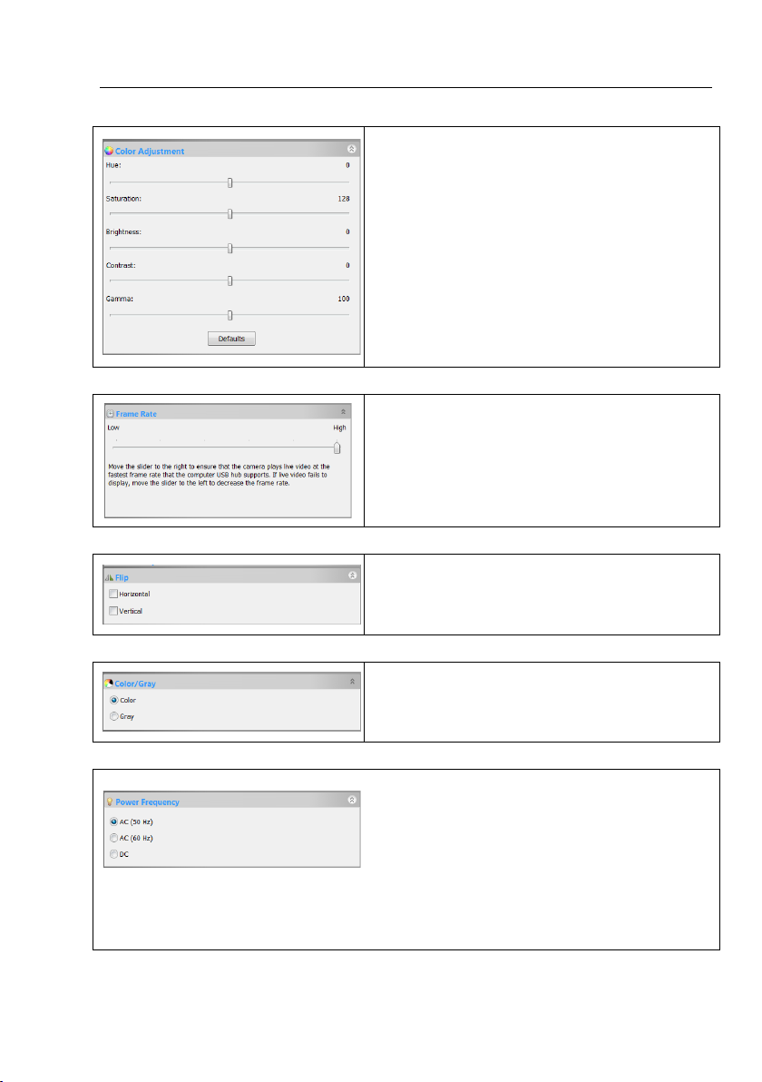
5.4 Color Adjustment group
1. Hue: Adjusts the Hue of the image. Drag the slider to the right to
increase or drag to the left to decrease hue;
2. Saturation: Adjusts the Saturation of the image. Drag the slider to the
right to increase or drag to the left to decrease saturation;
3. Brightness: Adjusts the image Brightness. Drag the slider to the right to
increase or drag to the left to decrease the image's brightness;
4. Contrast: Adjusts the image Contrast. Drag the slider to the right to
increase or drag to the left to decrease the image's contrast;
5. Gamma: Adjusts the image Gamma. Drag the slider to the right to
increase or drag to the left to decrease the image's gamma;
6. Defaults: Click the Defaults to clear changes and reset to default ones;
7. All of your settings will be saved for future adjustment application.
Drag the slider to the right to ensure that the camera can capture the
Video at the fastest Frame Rate that your computer USB hub supports. If
Video fails to display, drag the slider to the left to reduce the Frame Rate
and enable the Video display available in a low speed mode.
If the Video on the screen appears in different directions from what is
viewed under the microscope or telescope, check the “Horizontal ” or
“Vertical” to set the Video direction to the right one.
If you wish to preview Color Video, select the “Color” button
If you wish to preview Gray Video, select the “Gray” button
1. A CMOS sensor captures each row of pixels (from top to bottom) in
sequential order, creating a rolling effect, hence th e name "Rolling Shutter".
Instead of being relatively constant. So for example, as the commercial
mains frequency in Europe is 50Hz, fluorescent lights in Europe flicker
at 100 times per second and as the mains frequency in US is 60Hz, so in
the USA they flicker at 120 times per second;
2. This flickering problem is solved by capture row pixels in over the duration of integer number of (n) flicker periods;
3. Select 50HZ will delete the rolling dark band for the 50HZ fluorescent light fluctuation;
4. Select 60HZ will delete the rolling dark band for the 60HZ fluorescent light fluctuation;
5.5 Frame Rate group
5.6 Flip group
Help Manual
5.7 Color/Gray group
5.8 Power Frequency group
9
Page 18
5. For DC power, no light fluctuation is existing and no compensation is needed.
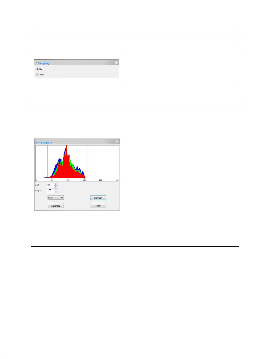
5.9 Sampling group
1. Bin: Pixel binning refers to the method of combining (averaging)
pixels of blocks of neighboring same color pixels;
2. Skip: Also called "Decimation", means that a certain amount of pixels is
not read out but skipped (horizontally, vertically or in both axes). This
reduces resolution of the resulting image but introduces subsampling
artifacts.
1. A Histogram illustrates how pixels in an image are distributed by
graphing the number of pixels at each color intensity level. The
Histogram shows detail in the shadows (shown in the left part of the
histogram), midtones (shown in the middle), and highlights (shown in
the right part).A Histogram can help you determine whether an image
has enough detail to make a good correction;
2. This dialog shows the Histogram of current active image. Two vertical
line markers show the upper and lower limits of the intensity levels.
These markers can be dragged with your mouse. If you are looking at a
color image, the Histogram will reflect the RGB(red, green and blue
channels histogram at the same time) R(red), G(green), and B(blue)
values with lines of the same color;
3. You can also enter directly the desired values in the Left or Right
boxes below the Histogram chart for both Left and Right Histogram
boundaries;
4. Click the “Refresh” button to update the Histogram display if the
sample under observation is moved or changed;
5. Clicking Defaults will return the Left and Right Histogram boundaries
to its original ones;
Click Auto to locate the two boundaries automatically to get the best
Video quality.
5.10 Histogram group
Help Manual
10
Page 19
Help Manual
6 File
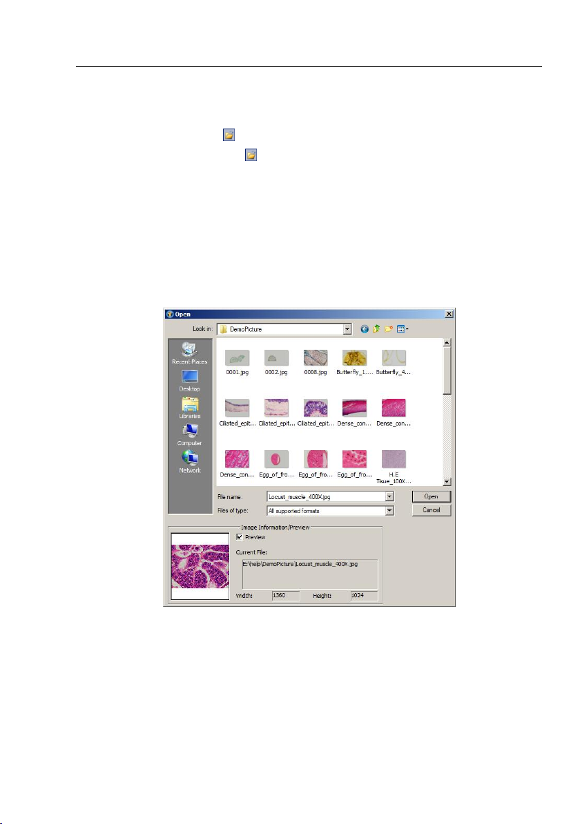
6.1 Open Image••• Ctrl+O
Choose File>Open Image••• command to open an existing image file. Open
Image••• can also be used to preview an image in small size, or to view its statistics
and information without actually opening the image itself. These capabilities can be
used to quickly locate a particular image.
ToupView supports and can open many image formats. These are identified in the
Files of type list box. You may also open an image file called ToupView File Type (*.tft)
with objects overlaid on it.
When open an image, ToupView places it into a new image window. It then becomes
the active image. More than one image can be opened within ToupView
simultaneously.
Note: ToupView maintains, at the bottom of the File menu, a list of the last 4 opened
files. Any of these files can be accessed by simply clicking on file name. If no files are
11
Page 20

Help Manual
listed (beneath Exit), the Open Image••• command must be used to open the file.
Also, View>Browse can be used to view images under any selected directory. Brief
information is given in View>Browse menu.
File name: From this list box, select the name of the file want to open. Either the type
of the file name (with its entire path, if it is not in the current folder), or selecting Files
of type to obtain a list of file names. Double-clicking a file name in the large list box
(where both folder and file names are listed) will automatically open it.
Note: If just type in the file name, be sure that the Files of type field correctly identify
the format of the file to open. Otherwise error messages will bring up when ToupView
tries to open the file.
Files of type: In this list box, select the image format of the file to open. If one selects
All supported formats, ToupView uses the file's extension to identify its format.
ToupView supports the following file formats:
Window Bitmap(*.bmp,*.dib,*.rle)
JPEG(*.jpg,*.jpeg,*.jpe,*.jif,*.jfif)
Portable Network Graphics(*.png)
Tag Image File Format(*.tif, *.tiff)
Compuserve GIF (*.gif)
Targa(*.tga)
PhotoShop(*.psd)
ICON(*.ico)
Enhanced Window Metafile(*.emf)
Window Metafile(*.wmf)
JBIG(*.jbg)
Wireless Bitmap(*.wbmp)
ToupView File Type(*.tft)
If the image file does not use standard format-identifying extensions, the file in the
File name field must be typed, and then select its format from the Files of type list
box. Otherwise, ToupView will select a format based on the file name extension.
12
Page 21
Help Manual
Preview: Click this button to preview image in small size. In preview mode, statistics
and information about the image (i.e. image Width, Height and image location) will
be displayed. The default is no Preview.
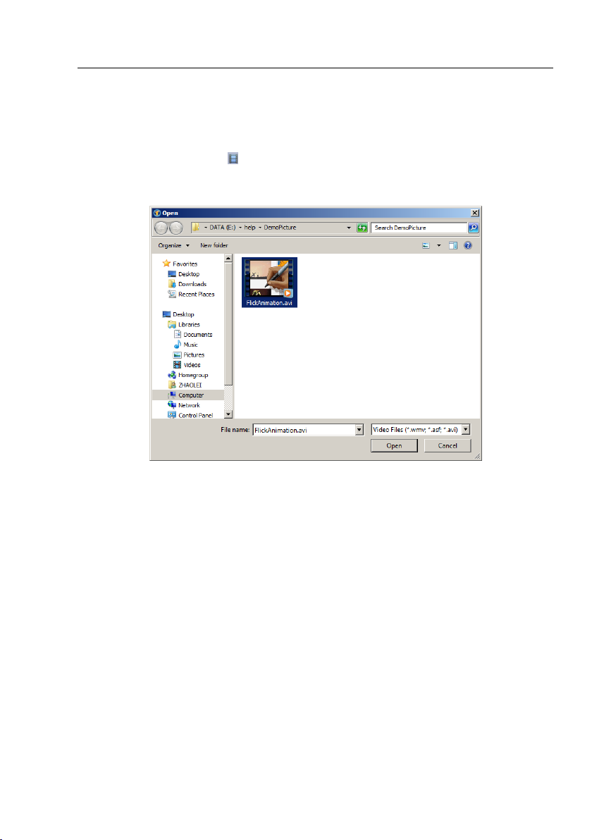
6.2 Open Video•••
1. Choose File>Open Video••• command to open an existing Video file;
2. Select the name of the file you want to open. If the file does not appear, select the
option for showing all files from the Files of Type in the list box. The Video file type
can be *.wmv*;*.asf* or *.avi* format.
3. Click Open to open a Video file, this will create a Video window and begin to start
the Video stream. Your Video window will be associated with the name of “Video
[XXX.XXX]” (i.e., its title bar will display “Video [XXX.XXX]”, here, XXX.XXX is the
Video file name).
4. Click Cancel to return to the application area.
Note: Only a single Video can be opened at a time. ToupView takes camera as an
extra Video file, if the camera Video window is opened, this menu will be disabled and
the Video file cannot be opened anymore.
13
Page 22
Help Manual
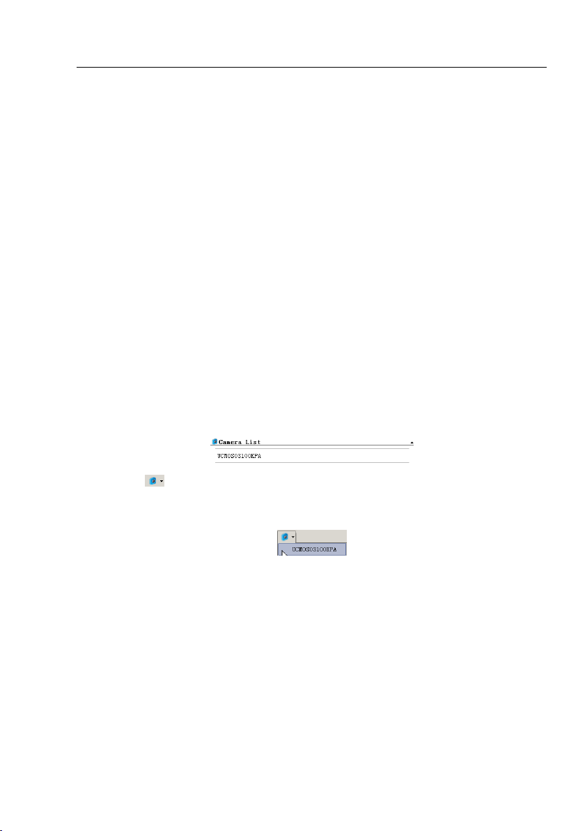
6.3 Camera List
ToupView will detect all of the cameras that your computer has installed (Here, it is
UCMOS03100KPA, a 3.1M pixel CMOS camera) and will append all the camera names
as submenu to File>Camera List menu (Here, the submenu name is
“UCMOS03100KPA”).
Choosing File>Camera List> UCMOS03100KPA will create a Video window and begin
to start the Video stream. Your Video window will be associated with the name of
“Video [UCMOS03100KPA]” (i.e., its title bar will display “Video
[UCMOS03100KPA]”).
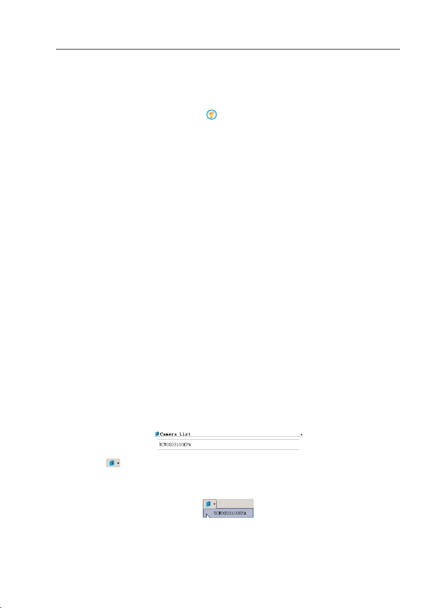
There are 3 methods to start the camera Video stream, they are:
1. Choose File>Camera List>UCMOS03100KPA (Here, a 3.1M pixel camera is
installed) command to create the camera Video window;
2. Click Camera bar (If it is not activated) and Camera List to expand the Camera List
group (if not expanded). Click the camera name (Here it is UCMOS03100KPA) to
create the Video window;
3. Click the ’s down arrow to expand the camera list and choose the right camera
(Here it is UCMOS03100KPA) to create the Video window.
Note: 1) Only a single Video can be opened at a time. ToupView takes camera as an
extra Video file, if the camera Video window is opened, the File>Open Video••• menu
will be disabled and the Video file cannot be opened anymore;
2) If a Video file is opened, the camera cannot be started.
6.4 Twain: Select Device•••
Twain is a cross-platform interface for acquiring images captured by certain scanners,
digital cameras, or frame grabbers. The manufacturer of the Twain Device must
14
Page 23
Help Manual
provide a Source Manager and Twain Data Source to work with ToupView.
Select the active device for Twain: Acquire••• from all devices available in the device
list box which are enumerated by the application.
One must install the Twain Device hardware and its driver first. See the
documentations provided by the device manufacturer for the installation
instructions.
Before begin to start Twain:Acquire at the first time with ToupView, choose
File>Twain:Select Device••• command first, then select the device. One does not
need to repeat this step for subsequent choosing of the Twain:Acquire••• command.
6.5 Twain:Acquire•••
Introduction
There are basically two techniques used to capture the video images from video
devices such as a PC camera, digital camera, and scanner. They are the
Twain:Acquire••• technique and the DirectShow technique (previously called VFW).
The most obvious characteristics of the Twain technique is that it displays the Video
in smaller resolution but captures the image in high resolution. The USCMOS and
UHCCD series cameras support all of these two image capture techniques.
Steps for Twain Acquire
Here we illustrate how to capture the image using a UHCCD01400KPA (1.4M pixels,
USB2.0) camera as an example.
1. Install the camera driver (for example driver for UHCCD01400KPA hardware);
2. Install ToupView;
15
Page 24
Help Manual
3. Plug the cameras UHCCD01400KPA (USB2.0) into the computer;
4. Start ToupView;
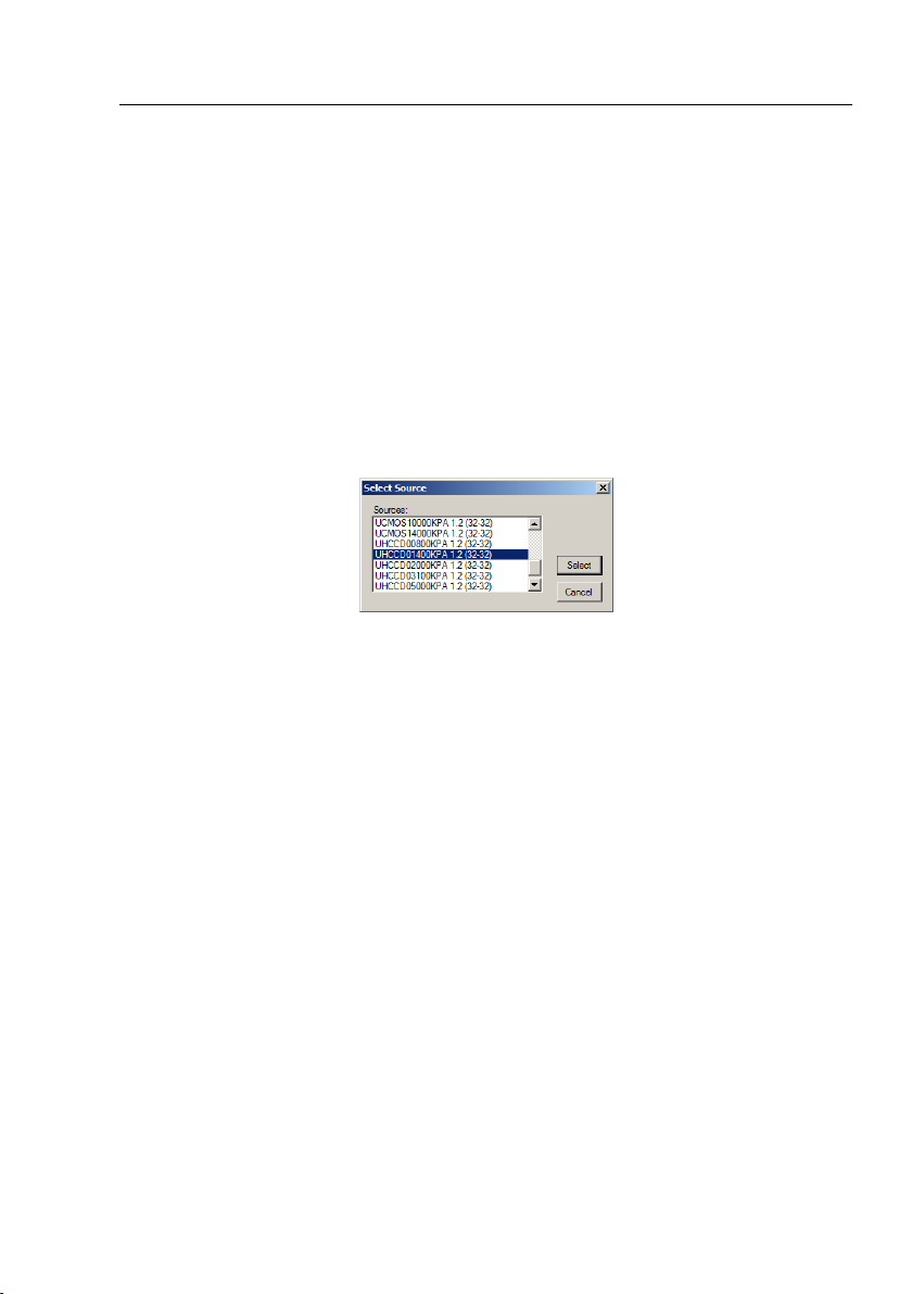
5. Choose File>Twain:Select Device••• command to select the device
UHCCD01400KPA from the Select Source dialog;
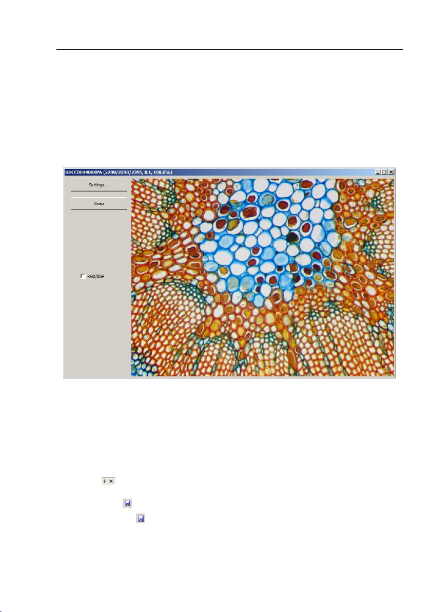
6. Choose File>Twain:Acquire••• command. There should be a dialog box like below:
In this dialog, Video Resolution can be selected (dropdown list if it has). The Video
Source Property••• can be set by clicking the Setting••• button. Click the Capture
button to capture an image. This will create a new window and its title bar will be
assigned a digital as the Image window name;
Check RGB/BGR to ensure the correct color encoding format.
Click x on to close the Twain:acquire dialog.
6.6 Save Ctrl+S
Choose File>Save command to immediately store the contents of the current
window to its file (the file listed on the window's title bar) while leaving the image still
16
Page 25

Help Manual
active in its window. If the image is in an untitled window, ToupView will issue the
File>Save As••• dialog.
The File>Save command can be used to save the most recent changes to disk. It is
often performed as a precautionary measure during lengthy or involved processes to
reduce the amount of reprocessing that might be required in the event of a system
failure or operational error. When an image is closed and not to save its changes is
chosen, ToupView discards all changes made since the last File>Save operation.
Note: 1).The File>Save command always saves the contents of the entire window,
even if there is an AOI (Area of Interest) defined within it;
2).The File>Save command will be disabled if the file is not changed or the
changes have been saved.
6.7 Save As•••
Choose File>Save As••• command to store the contents of the current window to a
specified file format. At the end of a File>Save As••• operation, the image window
will be associated with the new file and the new format (i.e., its title bar will display
the new file name). ToupView supported file save formats are:
Window Bitmap(*.bmp,*.dib,*.rle)
JPEG(*.jpg,*.jpeg,*.jpe,*.jif,*.jfif)
Portable Network Graphics(*.png)
Tag Image File Format(*.tif, *.tiff)
Compuserve GIF (*.gif)
PCX(*.pcx)
Targa(*.tga)
JBIG(*.jbg)
ToupView File Type(*.tft)
Save in: Find the folder where the file wishes to be saved. A new folder may be
created using the New Folder button.
File name: Enter to be saved file name. To specify the file's location, either enter its
entire path (disk and folder), or specify its location using the Save in list box.
17
Page 26
Help Manual
Image quality
If one save an image in JPEG format (*.jpg), one may
adjust image quality in the edit box. The values range
from 0 to 100. Default value: 75.
Progressive
The default is unchecked.
Save as type: In this list box, select the format in which the image wants to be saved.
Save As is also used to convert a single image from one format to another. For
example, if a TIFF file needs to convert to PCX format, open the TIFF image first, then
choose Save As command with the PCX format option to save it to a new file.
The Save As command has several important uses beyond simply storing an image to
a new file name. Click Option to select the different parameters to encode the file.
For JPEG (*.jpg,*.jpeg,*.jpe,*.jif,*.jfif), Option has the following items:
18
Page 27
Help Manual
Optimize Huffman codes
The default is unchecked.
Smoothing
The values range between 0 and 100. Default value: 0.
Save these setting as
defaults
When saving a file, the current settings will be saved as
defaults for the next file save operation.
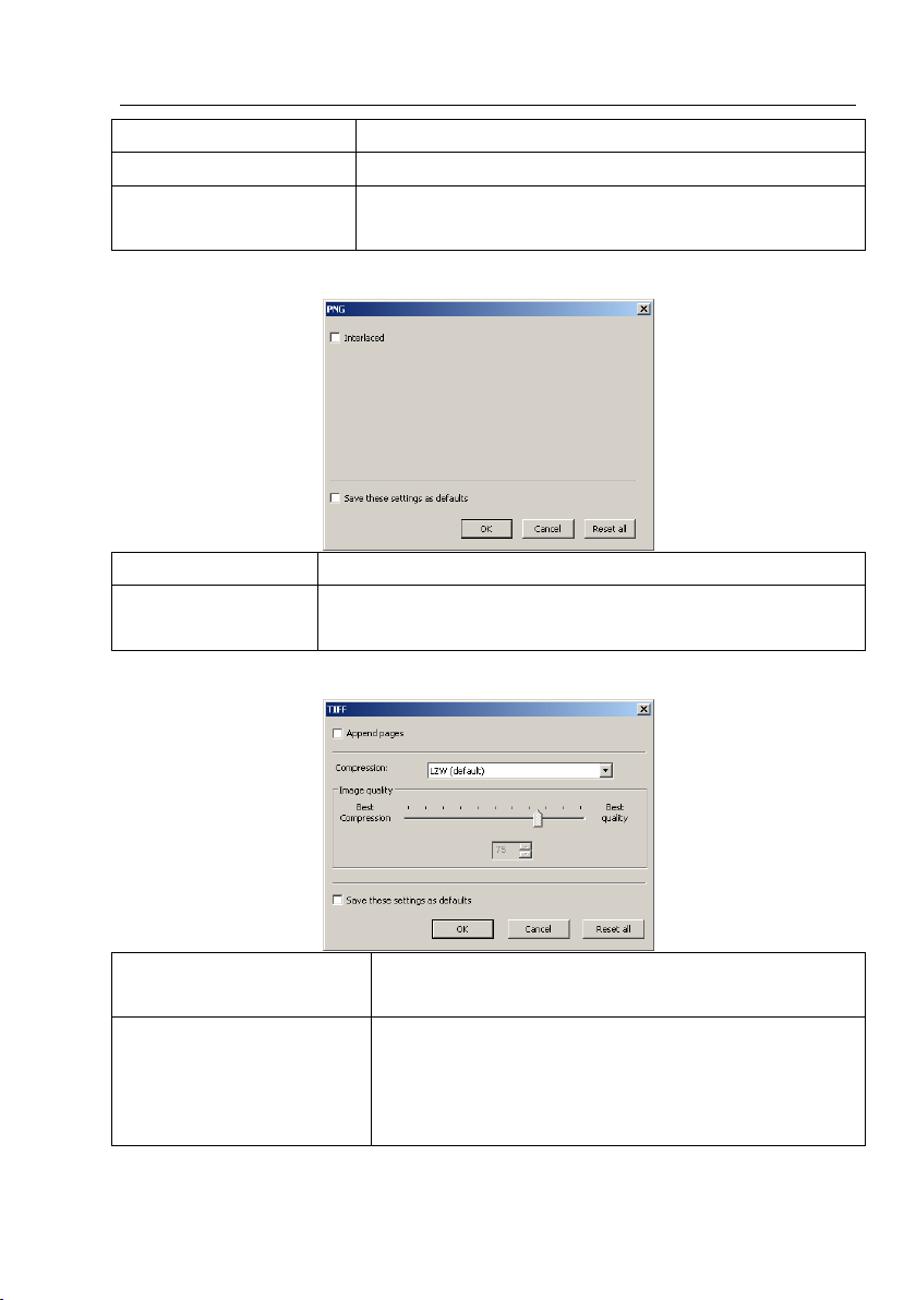
Interlaced
The default is unchecked.
Save these setting as
defaults
When saving a file, the current settings will be saved as
defaults for the next file save operation.
Appended pages
Determine whether the current image will be saved in
multiple pages style or not.
Compressions
Specifies a method for compressing the composite
image data. For saving a 32 ‑ bit TIFF file, one can
specify that the file be saved with predictor
compression, but have no option to use JPEG
For Portable Network Graphics (*.png), Option has the following items:
For Tag Image File Format (*.tif, *.tiff), Option has the following items:
19
Page 28
compression. Predictor compression offers improved
compression by rearranging floating point values, and
works with both LZW and ZIP compression.
Image quality
If choosing Compressions as "JPEG", the Image quality
can be adjusted by the slider bar. The values range
between 0 and 100. Default value: 75.
Save these setting as
defaults
When saving a file, the current settings will be saved as
defaults for the next file save operation.
For
Compuserve GIF (*.gif)
PCX(*.pcx)
Targa(*.tga)
JBIG(*.jbg)
ToupView File Type(*.tft)
There is no Option.
Help Manual
Note: 1) Detailed information of the above academic terminologies can be found in
books about image processing and image compression or on the internet;
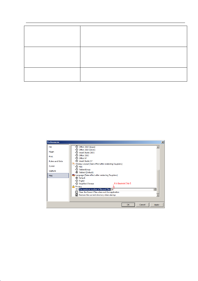
2) The file saved directory can be restored for future application. To keep the
directory unchanged when ToupView is started again, choose
Options>Preferences••• command, click Misc page and check Restore the current
20
Page 29
Help Manual
directory when startup under the Privacy item.
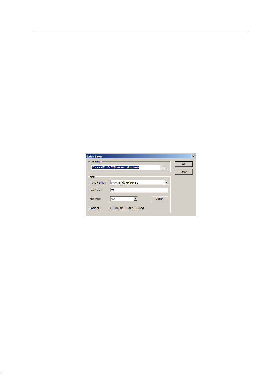
6.8 Batch Save•••
If many files have been snapped and needed to be saved. Choose File>Save As•••
command to realize the save target. But this will be time-consuming. The Batch
Save••• command runs File>Save As••• command with the name automatically
specified according to the paradigm specified in the Batch Save dialog
To start File>Batch Save••• command, you have to
1. Start the camera;
2. Snap at least an image first;
3. Choosing File>Batch Save••• command will bring up a Batch Save dialog:
Directory: Enter the name of the drive and directory into which your captured images
will be saved. You may either type the path information, or use the Browse button to
select it from a standard File dialog box.
Name Format: The year, month, date, hour, minute and second or nnnn(sequence)
are used to name the file. If more files are saved with in a second, a (xx) is suffix is
attached to the end of Name Format to avoid the possible same name appeared. For
nnnn(sequence) Name Format, no suffix is needed.
File Prefix: Enter a file name “prefix” for ToupView to use when generating files
names for a series images. This prefix will be combined with Name Format to form a
file name.
File Type: In this list box, select the format in which you want the image to be saved
21
Page 30

Help Manual
(can be BMP, JPG, PNG, TIF). Click Option button to select the different parameters
to encode the file (For BMP format, the Option will be disabled. See File>Save As•••
menu about the details of the format encoding methods);
Sample: The final file name is shown at the right of the Sample: label for reference.
4, If everything was finished, click OK button to begin the file batch save process or
Cancel to cancel the File>Batch Save••• command and return to the application
area.
Note: 1) In the process of the File>Batch Save••• command, the title on the Image
tab will be modified with the file name specified in the Batch Save dialog.
2) The File>Batch Save••• will be disabled if all the modified files are saved. It
will be enabled again if more than 1 file is modified.
6.9 Paste as New File•••
Choose File>Paste as New File••• command to place the contents of the clipboard
image into a new image window, which becomes the active image.
Before Choosing File>Paste as New File••• command, valid image data must be
copied to the clipboard first (see the Edit>Copy menu). If there is no image data on
the clipboard, the File>Paste as New File••• menu will be disabled.
The new image type will be the same as that of the original image. To upView will
accept image data from other applications via the clipboard as long as it is in
Windows Bitmap (DIB) format.
Note: ToupView will assign title the only digital to the window.
6.10 Print Setup•••
Choose this command to access the setup panel for the printer that have selected.
ToupView will present the standard setup panel for the particular printer (this is the
same panel one would receive if one were setting up the printer from the Windows
Control Panel). Change printer's setup to satisfy the requirements, click OK button to
return.
22
Page 31

Help Manual
6.11 Print Preview••• Ctrl+Shift+P
Choose Print Preview command to see the real-time effect of the printer without
actually printing it out.
6.12 Print••• Ctrl+P
Choose File>Print command to print one or more copies of the current image to the
selected output device. The ToupView File>Print command lets one take full
advantage of the printer's capabilities. If the printer has built-in half-toning or color
dithering capabilities, use them or instruct ToupView to perform these processes
before sending the image to the device.
The File>Print command also has facilities that let one adjust the size and position of
the image on the printed page.
6.13 Recent Files
ToupView maintains a recent 4 (default) most recently opened document files under
the Print menu. Choosing one of these menus immediately will reopens that file.
1. The maximum number of Recent Files can be modified by choosing
Options>Preferences••• command and clicking Misc page. Here, clicking the 4
(default) edit box will allow you to enter the number of items that you want. The
values range from 0 to 8;
2. One can also check Clear the Recent Files when exit the application to clear the
Recent Files.
23
Page 32

Help Manual
6.14 Exit
Choosing File>Exit command will close all of the active images and remove their
windows from the screen. After all of the images are closed, ToupView will end itself.
Note: If an image has been modified before attempting to Exit it, ToupView will issue
a warning to ask if user want to save the image or not first.
24
Page 33

Help Manual
7 Edit
7.1 Undo/Redo Ctrl+Z
Most of the operations in ToupView can be undone. Alternatively, one can restore all
or part of an image to its last saved version. The basic Undo process is:
1. Choose Open Image••• to open an image;
2. Choosing Image>Adjust>Auto Level, then Edit>Undo will be enabled;
3. Choosing Edit>Undo command will cancel the Image>Auto Level operation and
return the image to its initial opened state.
If return to the Edit menu, one will find that Edit>Undo now becomes Edit>Redo. You
can select one of these two operations to see the Undo and Redo mechanisms:
1. Choosing Edit>Redo will return the image to Image>Auto Level status and
Edit>Undo will be enabled again;
2. Choosing Image>Auto Contrast, then Edit>Redo will become Edit>Undo;
Note: ToupView supports only one step Undo and Redo operations.
7.2 Forward
25
Page 34

Help Manual
This command will move the current displayed image to the next step listed in the
Undo/Redo sidebar (If it is not in the final step).
Forward Demo
1. Open an image, choose Image>Adjust>Auto Level, choose Image>Adjust>Invert
and check Current on Index 1(Open Operation).
Now we continue the Edit>Forward demo. Since it is in Index 1, Edit>Backward is
disabled and Edit>Forward is enabled. The status is shown in Fig.1.
2. Choosing Edit>Forward, the image and the Index will advance forward to Fig.2.
Now Edit>Backward is enabled;
3. Choose Edit>Forward again to go to Index 3 as shown in Figure 3. Now
Edit>Backward is still enabled, but because it is in the final step, Edit>Forward is
disabled.
See Edit>Backward for further information.
7.3 Backward
26
Page 35

Help Manual
This command will move the current displayed image to the previous Index listed in
the Undo/Redo sidebar (If it is not in the "Open" status).
Backward Demo
1. Choose Open Image••• to open an image;
2. Choose Image>Adjust>Auto Level command;
3. Choose Image>Adjust>Invert command The final image is shown in Index 3.
Since it is in the final step (Fig.3), the Edit>Backward will be enabled;
4. Choosing Edit>Backward, the image and the Index will return to Index 2 as shown
in Fig 2. Since it is in Index 2, Edit>Forward will be enabled;
5. Choosing Edit>Backward again, both the image and the Index will return to Index
1 as shown in Fig.1. Since it is in the 3rd step, Edit>Forward will still be enabled, but
Edit>Backward will now be disabled.
See Edit>Forward for further information.
27
Page 36

Help Manual
7.4 Cut Ctrl+X
The Edit>Cut menu will be enabled only when an object or some objects on the Layer
is or are selected. See Measurements>Object Select or Edit>Select All menus
about how to select Layer objects for Edit>Cut operations
Choose Edit>Cut command to copy the selected Measurement objects to the
clipboard and delete the selected objects on the image. Any data already exist on the
clipboard will be replaced.
The data copied to the clipboard can be pasted into the active window or into another
opened image window on the extra layer using the Edit>Paste command (when there
is no Layer over the Background, ToupView will create a new Layer with blank name
and Paste the objects onto the new Layer over the image).
Note: 1.This command does not support Background Layer Cut operation.
7.5 Copy Ctrl+C
Choose Edit>Copy command to Copy the selected objects (on Measurement layer)
or an image's selected area on the Background Layer to the clipboard.
Copy the selected area on the Background layer to the clipboard.
1. Select the source area to Copy using the button on the Toolbar. The Copy menu
will be enabled;
2. Choose Edit>Copy command to copy the selected image area to the clipboard.
Copy object(s) on the Measurement layer to the clipboard.
1. For the Layer operation, see the View>Sidebar>Layer command and the Layer
menu in Sec.13 for details;
2. For the Measurement operation, see the View>Sidebar>Measurement command
and the Measurements menu in Sec.14;
3. After the Measurement operating has been done, choose Measurements>Object
Select command or check the Object Select button , the cursor will change to ;
28
Page 37

Help Manual
4. Move the mouse until the cursor becomes , this means the cursor is now
right on the Object. Clicking it will highlight and select the Measurements Object;
5. Optional 1: Continue to move the mouse until the cursor becomes , this means
the cursor is now right on another object. Clicking it with SHIFT+left mouse button
and the second object will be selected and highlighted;
6. Optional 2: (1) Move the cursor over the image, click down the left mouse button.
(2)Drag the mouse to draw a rectangle on the image. A dotted rectangle will appear
around the selected area. (3) Release the mouse and all of the Measurement objects
within the dotted rectangle will be highlighted and selected;
7. After the Measurement objects are selected, the Edit>Copy will be enabled;
8. Choose Edit>Copy to Copy the object(s) to the clipboard. Then the Edit>Paste
menu will be enabled. One can then Paste the objects onto the Current Layer or onto
the other Measurement Layer. If one switches to the Background Layer, the Paste
command will be disabled, but if one returns to the Measurement Layer, the Paste
command will be enabled again.
Note: 1) If there is no Measurement object selected, the Edit>Copy command will be
disabled. Edit>Copy will not delete the Measurement objects over the image. Any
data already existing on the clipboard will be replaced with the new data;
2) The copied object(s) can be pasted into the active window or into another
opened window using the Edit>Paste command as long as the current window is not
on the Background Layer (the command is disabled). See the View>Sidebar>Layer
29
Page 38

Help Manual
command and the Layer menu in Sec.13 for details.
7.6 Paste Ctrl+V
Choose Edit>Paste command to put objects from the clipboard onto the active
image's Measurement Layer. One can also choose Edit>Paste command to transfer a
layer's Measurement objects from one image window's Measurement Layer to
another image's Measurement Layer.
Note: 1) Before executing the Edit>Paste command, valid Measurement object must
have been copied into the clipboard (see the Edit>Copy command). If there is no
Measurement object data in the clipboard, the Edit>Paste command will be disabled.
2) When the current layer is not the Background Layer, this command can be
activated as long as the clipboard has the Measurement object, otherwise, it is
disabled. This means that the command does not support the image area Edit>Paste
operation.
7.7 Image Select
The Edit>Image Select command can be used to mark ROI and Copy the selected
ROI to the clipboard. This command is only used to select the ROI on the Background.
Choosing Edit>Image Select command will turn the cursor into a “ ” shape.
To select an area, drag the mouse cursor across the image with the left button held
down until the area is selected. Release the button and the area will be marked.
Handles will appear on the area that will allow alter the selection after it is marked.
Choosing Edit>Image Select command will check this menu (or click on the
30
Page 39

Help Manual
toolbar will keep it down). After the area is selected, the Edit>Copy button (or
menu) will be enabled and then the selected area can copy to the clipboard for
further application.
Note: Only when the Current is checked on the Background item, the Edit>Copy
command can copy the selected to the clipboard.
7.8 Select All Ctrl+A
Edit>Select All command is used to select the Current object(s) (Background image
or all of the Layer objects) at a time.
7.8.1 Select All on the Background layer
To Select All pixels on the Background layer within the canvas when the Background
layer is active, choose Edit>Select All command (shortcut: Ctrl+A).
7.8.2 Select All objects over the Background layer
When the Background Layer is not active, choosing Edit>Select All command will
select all of the objects on the Current Layer.
7.9 Select None Ctrl+D
Deselect any selected area on the image or the Measurement objects on a Layer.
1. When the Current Layer is the Background Layer and an image area is selected,
the Select None option will be enabled. Choosing Edit>Select None will delete the
dotted rectangle representing the selected area;
2. When the Current Layer is not the Background Layer and the Measurement
objects are selected, the Edit>Select None command will be enabled. Choosing
Edit>Select None will deselect all of the selected Measurement objects.
Note: Check Edit>Image Select, Edit>Select All and Measurements>Object Select
to understand how to perform select operations.
7.10 Inverse Selection
This command is for Browse window only.
When organizing files, one can invert a selection in order to select all of the files that
31
Page 40

Help Manual
were not previously selected. Click Edit>Invert Selection to inverse selection.
7.11 Delete File Delete
This command is for Browse window only.
You can Delete or remove one or more files from the Browse window. The steps are
as follows:
1. Select one or more files by a) Clicking the displayed file icons; 2) Clicking the files
with CTRL+left mouse button; 3) Dragging the mouse to draw a dotted line rectangle
across the files you wish to delete;
2. a) Press Delete key to delete the selected files; b) Click you right mouse button to
bring up a context menu, choose Delete command to delete the selected files. A
Confirm File Delete dialog will bring up. In the Confirm File Delete dialog, click Yes to
move the file to the desktop recycle bin, or No to cancel.
32
Page 41

Help Manual
8 View
8.1 Browse Ctrl+B
8.1.1 Open the Browse window
1. Choose View>Browse from the View menu or click the Browse toolbar button
to browse images on the hard disk;
2. Click Folders sidebar to activate it and double-clicking the listed directory in the
Folders sidebar will create the Browse window.
After creating the Browse window, ToupView will display a Browse window that looks
like windows explorer. The child window on the left part of the Browse window called
Folder is used to browse images on the hard disk. Images in the current directory are
displayed in Large Icons or Small Icons mode on the right side of the Browse window.
Their order can be set according to the sorting methods (Forward and Reverse) you
selected (Sort by Name, Type, Size, Width, Height).
8.1.2 Browse window right mouse button context menu
Clicking the right mouse button on the list icon in the Browse window will bring up a
right mouse button context menu:
These context menu functions are described in
View>Delete File
View>Sort>Sort by Names
View>Sort>Sort by Type
View>Sort>Sort by Size
View>Sort>Sort by Width
33
Page 42

Help Manual
View>Sort>Sort by Height
View>Sort>Forward
View>Sort>Reverse
View>Icon>Large Icons
View>Icon>Small Icons
View>Refresh for details
Note: The Browse can be used to perform tasks such as creating new folders,
renaming, moving, and deleting files. Individual file information and import data
from digital cameras can also be displayed. Double-clicking the left mouse button on
the icon will open the image as an active image in full size. See ToupView’s image
window UI for more details.
8.2 Sort>Sort by Names
This command is for the Browse window only.
Sort the image files in order of names in the Browse window.
8.3 Sort>Sort by Type
This command is for the Browse window only.
Sort the image files in order of type in the Browse window.
8.4 Sort>Sort by Size
This command is for the Browse window only.
Sort the image files in order of size in the Browse window.
8.5 Sort>Sort by Width
This command is for the Browse window only.
Sort the image files in order of width in the Browse window.
8.6 Sort>Sort by Height
This command is for the Browse window only.
Sort the image files in order of height in the Browse window.
8.7 Sort>Forward
34
Page 43

Help Manual
This command is for the Browse window only.
Sort the image files in order of the Forward mode (i.e. 1,2,3,4) in the Browse
window.
8.8 Sort>Reverse
This command is for the Browse window only.
Sort the image files in order of the Reverse mode (i.e. 4,3,2,1) in the Browse window.
The Sort settings are saved until they are changed. For example, if you sort images in
the Browse window according to the Type, the images will remain sorted according to
Type until the Sort settings are changed.
8.9 Icon>Large Icons
This command is for the Browse window only.
You can select different view modes in the Browse window. The Thumbnail view
mode displays small images previews.
Choosing Icons>Large Icons will display the image files in Large Icon format in the
Browse window.
8.10 Icon>Small Icons
This command is for the Browse window only.
You can select different view modes in the Browse window. The Thumbnail view
mode displays small images previews.
Choosing Icons>Small Icons will display the image files in Small Icon format in the
Browse window.
8.11 Refresh F5
This command is for the Browse window only.
If the files under the Folders are altered outside of ToupView, after switch back to
ToupView, one can Refresh the image files in the current directory to update the
Thumbnails.
35
Page 44

Help Manual
Choose Refresh to refresh the image files in the Browse window.
8.12 Measurement Sheet
When choosing View>Measurement Sheet command, the Measurement Sheet
shows the object's possible features, such as Name, Center Point, Radius, Area,
Perimeter, Angle, Start Point, and End Point overlaid on the extra layer.
Clicking the right mouse button on the Measurement Sheet••• and the above context
menus or context submenus will be brought up on the Measurement Sheet•••:
8.12.1 File Import•••
Choose this command to load a Measurement file (*.measurement) and display it
over the current image background.
8.12.2 File Save•••
Choose this command to save the Measurement objects over the current image
background on the Current Layer to a Measurement file (*.measurement).
8.12.3 Export>To Html File
Export the Measurement objects to the *.html file in tabbed format.
Note: This menu will be enabled only when there are Measurement objects over the
Background Layer.
8.12.4 Export to Excel
If this command is chosen, the Measurement objects over the image will be exported
36
Page 45

Help Manual
to Microsoft Excel with the Measurement object and image together. The objects'
parameters in the Measurement Sheet will also be exported as a table on the same
frame with the image.
Note: This menu will be enabled only when there are Measurement objects over the
Background Layer.
8.12.5 Auto Highlight
When this menu is checked, clicking the row in the Measurement Sheet will Highlight
the corresponding Measurement object over the Background Layer. Clicking the
object over the image will Highlight the corresponding row in the Measurement
Sheet.
8.12.6 Settings•••
37
Page 46

Help Manual
1. To modify the Measurement Sheet’s item order. Select an item, and click the Up or
Down button to move the selected item forward or backward;
2. Checking/Unchecking the item will show/hide the item in the Measurement Sheet;
3. Clicking Default will return to the ToupView's default settings.
8.13 Sidebar
There are 5 sidebars for the ToupView frame window. They are Camera sidebar,
Folder sidebar, Undo/Redo sidebar, Layer sidebar and Measurement sidebar.
8.13.1 Sidebar overview
AA: Camera sidebar; AB: Camera sidebar pages for the control of the activated
camera.
BA: Folder sidebar; BB: Back to the previous folder;
BC: Forward to the previous folder;
BD: Browsing the pictures under the directory of ToupView’s directory;
BE: Auto hide button to show/hide the current selected directory, this will open the
Browse window if it is not opened (Double-clicking on the selected directory will
perform the same functions.);
BF: Folder to locate the Browse window folder.
CA: Undo/Redo sidebar;
CB: Paste the checked Current step to a new image window; User can also drag the
selected step to the window to setup a new image window for the dragged step;
CC: Removing the highlighted step from the Undo/Redo list (will be enabled only
when a list item or step is selected);
38
Page 47

Help Manual
CD: Indicating which step is the Current one displayed in the image window;
CE: Step Index; CF: Operation name.
DA: Layer sidebar; DB: Make a New layer; DC: Remove a layer;
DD: Set the Current layer; DE: Show/Hide a layer; DF: Rename a layer;
DG: Visibility control of the layer items;
DH: The Current active layer for operations;
DI: Layer Name; the image layer is always named as “Background” See details about
the Layer sidebar in Layer Operations.
EA: Measurement sidebar;
EB: The Appearance of the select item on the Current layer; you can edit the
Appearance by click it and edit it.
EC: The Calculation of the select item on the Current layer;
ED:. The Coordinate of the select item on the Current layer; you can edit the
Coordinate by clicking it and edit it.
8.13.2 Sidebar>Camera
Camera sidebar is mainly used for the control of Toupcam, it included 11 groups. The
group can be expanded by clicking the group name or the arrow button at the right
of the group name; Choosing Sidebar>Camera will show/hide it on the frame.
8.13.3 Sidebar>Folder
Folder sidebar is mainly used for the image Browse control.
Checking View>Sidebar>Folder will show the Folder sidebar. Clicking its tree can
navigate the file directories.
Double-clicking the directory in the Folder will create the Browse window. If there are
image files stored under the tree that ToupView supports to open, the image files will
be displayed in Large or Small icons format. Their order can be set according to the
sorting methods (Forward and Reverse) you selected (Sort by Name, Type, Size,
Width, Height). Please check the Browse for details.
Clicking with the right mouse button on the directory will bring up the right mouse
39
Page 48

Help Manual
context menu as shown below:
This is the basic window explorer menu and will be explain it in this manual.
8.13.4 Sidebar>Undo/Redo
Undo/Redo sidebar is used to Undo/Redo the Image and Process menus’ image
operations.
8.13.5 Sidebar>Layer
Layer sidebar is used for the management of Layer operations. This operations
including making a New Layer, Removing a Layer or Renaming a Layer and Layer
visibility controlling et al.
8.13.6 Sidebar>Measurement
Measurement sidebar is used to edit the object on the Layer.
8.14 Ruler and Grid
Ruler and Grid menu has 3 submenus, they are:
8.14.1 Grids>No Grids
Choosing this command will remove both Manual Grids and Auto Grids overlaid on
the image.
8.14.2 Grids>Manual Grids
Choosing this command will display two small Right Arrow and Down Arrow overlaid
40
Page 49

Help Manual
on the top of the Vertical Ruler and on the left of the Horizontal Ruler as shown
below:
Move the mouse to the Down Arrow will show horizontal drag icons. Drag the Down
Arrow along the Horizontal Ruler to where ever you want. When it is dragged over the
image, there will be a Vertical line displayed to let you judge where to release this line
on the image. You can drag any lines to overlay them on the image.
Move the mouse to the Right Arrow will show vertical drag icons. Drag the Right
Arrow along the Horizontal Ruler to where ever you want. When it is dragged over the
image, there will be a Horizontal line displayed to let you judge where to release this
line on the image. You can drag any lines to overlay them on the image.
8.14.3 Grids>Auto Grids
Overlay the grids on the image automatically.
The Auto Grids can be set in the Ruler and Grids>Setting••• menu.
41
Page 50

Help Manual
8.14.4 Grids>Remove All Grids
Remove all of the Manually Grids or Auto Grids overlaid on the image.
8.14.5 Settings•••
Choosing this menu will show the Preference dialog. Click Ruler and Grids page. In
this page, one can select Ruler Color, Cursor Color, Grid Style, Line Style, and Line
Color.
Click OK to accept the settings or Cancel to return to the application area and cancel
the settings.
8.15 Best Fit
Choose Best Fit to automatically resize the Video or Image to fit in the window.
Note: Choosing this command will enable View>Actual Size menu.
8.16 Actual Size
Choose Actual Size to set the active image to its actual size (e.g. 100%).
Note: This option will be disabled if the image is currently viewed at 100%. At any
other zoom ratio, Actual Size will be enabled.
8.17 Track
If the image's actual size is larger than the Video/Image window, check this
command to move the Video/Image to display the ROI in the center. Its function is
similar to the scroll bars. It is an alternative to using the arrows on the scroll bars for
42
Page 51

Help Manual
positioning the Video/Image within the window.
Checking this menu will change the cursor to and the button on the Toolbar will be
checked.
Then keep down the mouse button to drag the region of interest on the Video/Image
to any location in the Video/Image window.
Note: If the Video/Image display area is smaller than the window size. The track will
be ineffective.
8.18 Properties
If an image file listed in the Browse is highlighted. Choosing View>Properties or
clicking on Browse window with the right mouse button will bring up a Properties
dialog as shown below:
43
Page 52

Help Manual
The file Properties dialog including 4 pages. They are General, Security, Details and
Previous Versions pages. They may depend on the operating system and we do not
discuss it in this help.
44
Page 53

Help Manual
Item
Description
Device ID
Unique ID to identify the camera device.
Device Name
Human readable string to identify the name of the camera
device.
9 Setup
9.1 Start/Pause
If the Video window is paused, one can continue the Video process by choosing
Start/Pause menu.
If the window is running, one can choose Start/Pause command to pause the Video
and choose Start/Pause command again to start the Video.
9.2 Full Screen
Choose Full Screen to display the Video window in full screen style. Press ESC to
enter Full Screen mode. Press ESC again will return to the default Video window.
Note: The window should be in focus to make the ESC command enabled.
9.3 View Properties•••
Setup>View Property••• will help you to understand the camera statistical
properties. Choose Setup>View Property••• command to invoke the View Property
dialog:
The items in the dialog are described in the following table:
45
Page 54

Help Manual
Still Image Capture
Whether or not the camera supports Still Image Capture. Still
Image Capture is used for high resolution camera to capture
an image with a different resolution from the video. This
feature is mainly used to capture high resolution image under
low resolution video to compromise the frame speed and the
image resolution.
Display Width
The Video window width.
Display Height
The Video window height.
Video Width
The actual Video window video width.
Video Height
The actual Video window video height.
Compression
The compression format of the Video stream.
Bits Per Pixel
Indicate how many bits are used to store on pixel.
Time (second)
Seconds elapsed since the Video has been started.
Frame
Frames acquired since the Video has been started.
Actual Frame Rate
Actual frame Rate of the Video stream.
Note: The Actual Frame Rate is listed for reference. It varies depending on the
computer's configuration. Different hardware configurations may have different
Actual Frame Rates.
9.4 Video Overlay•••
9.4.1 Video Overlay: Overlay
Choose Setup>Video Overlay••• command and click the Overlay page to overlay
Scale, Magnification, Date and Clarity Factor on the Video window.
This command will invoke Overlay page as above. The Position, Font Size, Font
Weight of the Scale, Magnification and Date, and Clarity Factor can be defined
46
Page 55

Help Manual
together. Their Colors can be defined separately.
Clicking OK and the Scale, Magnification and Date, and Clarity Factor will be overlaid
on the Video window. The Clarity Factor can tell if the sample is in good focused state.
The larger the Clarity Factor, the better the sample focused.
Note: To enable the Scale bar, the Magnification must be defined and selected at first.
The Unit can be any unit except Pixel. There are two methods to set the Unit, they
are:
1. Choosing Unit in the Unit dropdown list box( ) on the tool
bar which is just on the left of the Magnification dropdown list box;
2. Choosing Option>Measurements••• command, a dialog called Measurement will
bring up. Click Length Unit page and check the Unit in the Current to set the Unit.
9.4.2 Video Overlay: Marker•••
Choose Video Overlay: Marker••• to overlay Video Marker on the Video window. The
Video Marker type may be Cross, Rectangle, Circle, Cross+Rectangle, or
Cross+Circle. The Video Marker is shown as below:
Choosing “Cross+Retangle” in the Type list box and Video Overlay: Marker dialog will
become:
47
Page 56

Help Manual
Enter the Cross Width and Cross Height, Rectangle Width and Rectangle Height, x
Offset and y Offset, in their specific fields. Click Color••• to define the Video Marker
color.
Click OK to end the Video Marker dialog and a Cross+Rectangle Marker will be
overlaid over the image. There should be a Cross+ Rectangle marker on the Video
window as shown below:
Click Cancel to cancel the Video>Overlay: Marker operation and return to the
application area, or Apply to overlay the Marker on the Video and keep the Video
Overlay dialog there for further modification.
9.5 Video Watermark•••
Fig.1 shows a micro ruler. The dark lines can be extracted as Video Watermark and
48
Page 57

Help Manual
Fig.1 Captured Micro Ruler
Fig.2 Micro ruler after being binarized
Fig.3 Inverted 24 bits image
Fig.4 Video Watermark setup dialog
overlaid on the Video window. The steps are:
1. Choose Capture>Capture Image or click to capture the micro ruler
image as shown in Fig.1;
2. Choose Process>Binary••• command to binarize the image as shown in Fig.2;
3. Choose Image>Adjust>Invert command to invert the image and choose
Image>Color Quantize••• command to convert the image into 24 bits as in Fig.3.
Choose File>Save As••• command to save the image in 24 bit BMP format;
4. Choosing Setup>Video Watermark••• command and a dialog called Video
Watermark is brought up as shown in Fig.4. Click the button to locate the image
saved in step 3. Use the defaults Transparent (%)(50). If everything is ok, click OK
button. The final Video Watermark is overlaid on the Video window as shown in Fig.5.
49
Page 58

Help Manual
Fig.5 Video Window with Video Watermark overlaid
9.6 Move Watermark
9.6.1 Move to•••
If there is Watermark overlaid on the Video, this menu will be enabled.
Choosing Setup>Watermark••• command will bring up a Move dialog. Where one
can enter the X: and Y: offset value in their fields for the desired pixel move
distances.
9.6.2 Move to zero
If the Watermark was moved, this menu will be enabled. Choosing this menu will
move the Video Watermark to its original coordinates (0,0).
9.7 Rotate Watermark
9.7.1 Rotate to•••
If there is Watermark overlaid on the Video, this menu will be enabled.
Choosing Setup>Rotate Watermark>Rotate to••• command will bring up a Rotate
dialog, where one can enter an angle to Rotate the Video Watermark a specified
angle around the Video center (0, 0).
50
Page 59

Help Manual
9.7.2 Rotate to zero
If the Video Watermark was rotated, the Rotate to zero menu will be enabled.
Choosing this menu will rotate the Video Watermark to zero degree.
9.8 Gray Calibration•••
This function can make specified area image brightness a desired value among
various scenarios, achieving the continuity requirement of the observation. The Gray
Calibration steps are summarized as follows:
1. Click Exposure & Gain on the Camera sidebar to extend the Exposure & Gain group,
uncheck Auto Exposure box.
2. Choose Edit>Image Select command or click on the toolbar to select a
reference region, and choose “Setup>Gray Calibration” command. A dialog called
Gray Calibration will be brought up to display the current ROI Average Gray. Now the
brightness of the microscope light source can be adjusted until the Average Gray
closing to the desired value. Click “OK” to finish the calibration and return to the
application area. The desired value here is around is 200.
51
Page 60

Help Manual
9.9 Manual Fusion•••
Make sure that the ToupView package and UCMOS or UHCCD camera are correctly
installed. Turn on the microscope's light.
1. Run ToupView and start the camera;
2. Choosing Setup>Manual Fusion••• command or clicking on the toolbar will
bring up a dialog called “Manual Fusion”;
3. Use the microscope coarse or fine focus knobs to move the sample stage up and
down, in order to find the positions where the clearest regions of the whole sample
can be seen on the Video window;
4. Click Capture button to capture an image into the image list which will be used for
the fusion operation.
5. Unless there is more than one image is captured, the Clear buttons will not be
enabled. Unless there are more than two images being captured, the Fusion buttons
will not be enabled. If the captured images are not satisfactory, click the Clear button
to clear the captured images, and capture new images.
6. If enough images are captured, click Fusion to do the image fusion and the Manual
Fusion dialog will be closed automatically. If Fusion is clicked, please wait for some
time to get the final fusion result. The fused image will be displayed in a new active
Image window and its title bar will be associated with a name of a digital by ToupView.
Clicking Close will end the Manual Fusion and return to the application area.
Note:
1. Use the coarse and fine focus knobs to move the sample stage up and down;
52
Page 61

Help Manual
2. Clicking Capture button will capture the current image into the image fusion list;
3. Repeating steps 1-4 until there are enough images;
4. Clicking the Fusion button will start image fusion. Waiting for some time and a
fantastic fusion result will be displayed in a new Image window;
9.10 Video Source Property•••
This menu will be displayed and enabled only when the camera that supports
directshow interface is started.
Choose Setup>Video Source Property••• to invoke the Video Source Property dialog:
The Video Source Property includes several categories such as Color, Exposure,
Extended, Misc and ROI page etal. These pages are used for the control of your
camera.
Note: Different camera may have different control contents. If you have any
problems with these controls, try to contact your camera supplier to get the further
technique help. ToupView has no responsibility to help you about these controls.
9.11 Video Stream Format•••
This menu will be displayed and enabled only when the camera that supports
53
Page 62

Help Manual
directshow interface is started.
The ToupView Video Stream Format••• configuration dialog is shown below:
One can change the video format mode, frame rate, color space, compression
options and so on. Here, we only have the Video Size to select. Selecting the desired
one and clicking OK. This will give you a selected Video Size.
Click Cancel to cancel the selection and return to Video window without any changes
or Apply to apply the current selection to the Video with the Properties remain
opened.
Note: Different devices may have different user interfaces and items. Contact the
camera supplier for details.
9.12 Still Image Options•••
Some cameras can capture a still image with its sizes different from the Video stream.
The camera may have a “pin” that acts as a hardware trigger, or it may support
software triggering. A camera that supports still images capture will expose a still
image pin to the designer.
To capture a still image, one should first set the size of the image to capture. The size
is determined by the camera hardware. Here we show an example with
UCMOS08000KPA camera.
Choosing Setup>Still Image Options••• will show the following Properties dialog:
54
Page 63

Help Manual
It has 3264*2448, 1600*1200, and 800*600 resolutions. Select the desired one and
press OK to accept the selection, or Cancel to ignore the current selection. Click
Apply to apply the selection.
One can find if the device supports Still Image Capture or not by choosing
Setup>View Property•••.
If the Still Image Capture's Value is Y in the View Property••• dialog, this means that
the camera supports the Still Image Capture operation.
55
Page 64

Help Manual
10 Capture
10.1 Capture Image F8
During the Video preview, you can always choose Capture>Image Capture command
to capture the Video image.
After the image is captured, the captured image will be the current active window.
The Capture>Capture Image menu will be disabled. If you wish to capture image
again, click the Video window title to activate the Video window and the
Capture>Capture Image menu will be enabled again.
Note: 1) The “Snap” button on the Camera sidebar can continuously shoot
the image even if the Video window is not activated. Click this button on the Camera
sidebar to capture image quickly;
2) Only when the Video window is active, the Capture>Capture Image will be
enabled;
3) If the Live and Snap resolutions are different,ToupView need to switch the
resolution from Live to Snap in the background to capture an image with Snap
resolution. After the Snap is finished,ToupView will switch back to the Live resolution
to continus the Video stream process. Thus it will take more time to capture a still
image.
10.2 Time-lapse (Auto Capture)•••
This function can capture a sequence of pictures with the same time interval; you can
precisely set the time interval (2 to 3600 seconds) and the total number of images.
Choosing “Capture>Time-lapse (Auto Capture)•••” command will bring up
Time-lapse (Auto Capture) dialog shown below:
Directory: The file Directory can be select by clickin the Browse button.
File: The File name including Name of Format, File Prefix, File type. It can be a
combination of prefix, time and type and is shown in the Sample.
Time Slot: Time slot(Second,2-3600S) is a time segment to capture an image.
56
Page 65

Help Manual
Toutle Images: Checking Total Images will enable its edit box. You can enter the Total
Images (1-9999) to be captured. ToupView will stop the Time-lapse capture process
automatically when the Total Images are reached.
If Total Images is unchecked, ToupView will capture the images continuously until
you choose Capture>Stop Time-lapse (Auto capture) command to stop the
Time-lapse capture.
Click OK to begin the Time-lapse capture, or Cancel to cancel the Start
Time-Lapse(Auto Capture) ••• command.
After the Time-lapse capture is started, the Capture>Start Time-Lapse(Auto Capture)
••• will change to Capture>Stop Time-lapse (Auto capture). Choosing this command
will stop the Time-lapse capture.
There are a variety of image format available (they are bmp, jpg, png and tif) to save
the captured image. For example, when choosing jpg format, you can set the
parameters of “Options” to adjust its compression quality or encoding method.
Please check File>Save As••• for details.
10.3 Start Record••• F9
1. You can 1) choose Capture>Start Record••• command; 2) click “Record” button
on the Camera sidebar; 3) use the shortcut key “F9” to start recording
movies. The video format can be wmv/asf(recommended) or avi. Clicking Next will
bring up Video File dialog as below;
57
Page 66

Help Manual
2. Enter the video file name under 1.Set the name for the captured video file field and
click the Browse… button under 2 Select the directory for the video file item to locate
the video file directory. Click Back to return to the Video Format dialog, or Next to the
next step;
3. An Encoder dialog will be brought up. Here you can select the Encoder format, set
the Bitrat(Kbps)(256-16384), Quality (1-100) and Key Frames Spacing (1-30). Click
Back to return to the Video Format dialog, or Next to the next step;
58
Page 67

Help Manual
4. A dialog called Display Information will be brought up. Here you can enter Title,
Author, Copyright and Description to their fields. Click Back to return to the Encoder
dialog, or Next to the next step;
4. A dialog called Start to Capture will be brought up. Here you can check Time Limit
(Minutes 1-1440) and enter recording time (If checked); Input Time-lapse(1-100).
There is a Summary text to display what you have been defined. Click Back to return
to the Encoder dialog, or Finish to end the setup;
59
Page 68

Help Manual
5. After the Video capture is started. The button on the Camera
sidebar will become . Clicking will stop the capture
process, otherwise ,it will stop untill the Time Limit is reached. After the Video
capture process is finished. The on the Camera sidebar will become
for the future Record process;
6. You can choose File>Open Video••• command to display the captured video file in
the Video window;
7. Clicking on the Video window with you right mouse button will bring up a context
menu. It includes View Properties••• command to check the Video Properties,
Start/Pause command to start or pause the video and display the Video in Full Screen
mode. These commands can also be performed by choosing Setup>Start/Pause,
Setup>View Properties and Setup>Full Screen commands.
60
Page 69

Help Manual
11 Image
11.1 Mode
11.1.1 Color Quantize•••
The Color Quantize••• command is widely used to change the image bit. ToupView
supports the mutual changes among 1, 4, 8, and 24 bit images.
When the dialog is opened, the default checked color bit is the image's color bit.
Check the desired bit and click OK to end the command. The image will converted to
the selected color bits.
11.1.2 Gray Scale
Choose Gray Scale command to convert a color image (true color image or index
color image) to a gray scale image. If the original image is 24 bit, the new image is
8 bit. Otherwise the bit of the image will not be modified.
11.2 Adjust
11.2.1 Curve•••
Choose Curve••• dialog to adjust the entire tonal range of an image. But instead of
making adjustments using only three variables (highlight, shadow, midtone), one
can adjust any point on the curve along a 0-255 scale while keeping up to 15 other
values constant. One can also use Curve to make precise adjustments for individual
color channels on an image.
The horizontal axis of the graph represents the original intensity values of the pixels
(Input levels).
The vertical axis represents the new color values (Output levels). In the default
diagonal line, all of the pixels have identical Input and Output values.
61
Page 70

Help Manual
Curve: Drag the Curve until the image looks satisfactory.
Pencil: Check the pencil button at the bottom of the dialog, and drag it to draw a new
arbitrary Curve.
Channel: To adjust the color balance of the image, check the channel(R, G or B) from
the Channel button. Check the white button to select RGB channels at the same time,
which is located on the left of the R (Red), G (Green) and B (Blue) buttons.
11.2.2 Auto Level
The Auto Level command moves the level's sliders automatically to set highlight and
shadow. It defines the lightest and darkest pixels in each color channel as white and
black and then redistributes the pixels' color values proportionately. Since Auto Level
adjusts each color channel individually, it may remove or introduce color casts. The
Auto Level command moves the level's sliders automatically to set highlight and
shadow. It defines the lightest and darkest pixels in each color channel as white and
black and then redistributes the pixels' color values proportionately. Since Auto Level
adjusts each color channel individually, it may remove or introduce color casts.
By default, this feature clips the white and black pixels by 0.5%--that is, it ignores
0.5% of the lightest pixels and 0.5% of the darkest pixels when identifying the
lightest and darkest pixels on the image. Choose Options>Auto Correction•••
command to modify this default setting. This ensures that white and black values are
representative without being determined by extreme pixel values. The Auto
Correction••• dialog is shown below:
62
Page 71

Help Manual
Auto Level gives good results when an image with an average distribution of pixel
values needs a simple contrast adjustment or when an image has an overall color
cast. However, adjusting the Curves manually is more precise.
See Auto Contrast for another auto adjust command.
11.2.3 Auto Contrast
The Auto Contrast command automatically adjusts the overall contrast and mixture
of colors in an RGB image. Since it does not adjust channels individually, Auto
Contrast does not introduce or remove color casts. It maps the lightest and darkest
pixels in the image to white and black, which makes highlights appear lighter and
shadows appear darker.
When identifying the lightest and darkest pixels on an image, Auto Contrast clips the
white and black pixels by 0.5%--that is, it ignores the first 0.5% of either extreme.
Choose Options>Auto Correction••• menu to modify this default setting. This
ensures that white and black values are representative without being determined by
extreme pixel values. The Auto Correction••• dialog is shown below:
Auto Contrast can improve the appearance of many photographic or continuous-tone
images. It does not improve flat-color images.
See Auto Level for another auto operation.
11.2.4 Histogram Equalization
63
Page 72

Help Manual
RGB
ToupView uses the RGB model. It assigns an intensity value to each pixel
ranging from 0 (black) to 255 (white) for each of the RGB components in a
color image.
For example, a bright red color might have an R value of 246, a G value of 20,
Histogram Equalization is a kind of histogram process. The histogram can reflect the
statistical information for the R, G, and B of the pixels of the original image. The
algorithm calculates each separately, equalizes the R, G, and B of the points linearly,
and reassigns them
11.2.5 Brightness/Contrast•••
The Brightness/Contrast••• command offers simple adjustments to the tonal range
of an image. This command makes the same adjustment to every pixel in the image.
The Brightness/Contrast command does not work with individual channels and is not
recommended for high-end output because it can result in the loss of details about
the image.
Preview: Check this button to display real-time effects when drags the slider bar.
Brightness: Dragging the slider bar to the left decreases the level and dragging it to
the right increases the level. The numbers on the right of the slider bar displays the
Brightness value. Values can range from -100 to +100.
Contrast: Dragging the slider bar to the left decreases the level and dragging it to the
right increases the level. The numbers on the right of the slider bar displays the
Contrast value. Values can range from -100 to +100.
11.2.6 Color•••
Choose Color••• command to modify the overall mixture of the colors in an image.
There are four color modules:
64
Page 73

Help Manual
and a B value of 50. When the values of all three components are equal, the
result is a shade of neutral gray. When the value of all components is 255, the
result is pure white; when the value is 0, pure black.
RGB images use three channels to reproduce up to 16.7 million colors
on-screen. In addition to being the default mode for new ToupView images, the
RGB mode is used by computer monitors to display colors. This means that
when working in color modes other than RGB, such as CMYK, ToupView uses
RGB mode for display on-screen.
Although RGB is a standard color mode, the exact range of colors represented
can vary, depending on the application or display device.
CMYK
The CMYK mode is based on the light-absorbing quality of ink printed on
papers. As white light strikes translucent inks, certain visible wavelengths are
absorbed while others are reflected back to the eyes.
In theory, pure cyan (C), magenta (M), and yellow (Y) pigments should
combine to absorb all light and produce black. For this reason these colors are
called subtractive colors. Because all printing inks contain some impurities,
these three inks actually produce a muddy brown and must be combined with
black (K) ink to produce a true black. (K is used instead of B to avoid confusion
with blue.) Combining these inks to reproduce color is called four-color process
printing.
The subtractive (CMY) and additive (RGB) colors are complementary colors.
Each pair of subtractive colors creates an additive color, and vice versa.
HSI
Based on the human perception of color, the HSI model describes three
fundamental characteristics of colors:
Hue is the color reflected from or transmitted through an object. It is measured
as a location on the standard color wheel, expressed as a degree between 0°
and 360°. In common use, Hue is identified by the name of the color such as
red, orange, or green.
Saturation, sometimes called chroma, is the strength or purity of the color.
Saturation represents the amount of gray in proportion to the hue, measured
as a percentage from 0% (gray) to 100% (fully saturated). On the standard
color wheel, Saturation increases from the center to the edge.
65
Page 74

Help Manual
Intensity is the relative lightness or darkness of the color, usually measured as
a percentage from 0% (black) to 100% (white).
HLS
The HLS model is very similar to the HLS color model. The main difference
between them is the calculation used to produce the brightness value. In the
HLS model, a pixel's brightness (L) is derived from its three (R, G and B) color
values. In the HLS model, a pixel's brightness (L) is determined by the
minimum and maximum values of its three color values.
Preview: Check this button to display the real-time effect when the slider bar's
position is modified.
The values beside the slider bar show the color changes in various color channels.
For RGB channel values, they can range from -100 to +100.
For CMYK channel values, they can range from -100 to +100.
For HSI channel values, the H value can range from -180 to 180, the S value can
range from -275 to 275, and the I value can range from -442 to 442.
For HLS channel values, the H value can range from -180 to 180, the L value can
range from -100 to 100, and the S value can range from -100 to 100.
11.2.7 HMS•••
Choose HMS••• command to adjust the HL (Highlight), M (Midtone), and S(Shadow)
parts of the image. Each part's value ranges from -100 to 100. This command is only
available for 24 bits true color image.
Preview: Check this button to display the real-time effect when one changes the
slider bar's position.
66
Page 75

Help Manual
11.2.8 Gamma•••
Gamma measures the brightness of midtone values produced by a device (often a
monitor). A higher gamma value yields an overall darker image.
Preview: Check this button to display the real-time effects when one changes the
slider bar’s position.
Gamma: Dragging the slider bar to the left decreases the level, while moving it to the
right increases the level. Values can range from 0 to 3.0.
11.2.9 Filter Color•••
Choose Filter Color command to filter a special color channel from a color image.
select either Red, or Green, or Blue color to filter. For every pixel, if select Red color
to filter, only information about the red channel will be discarded, and Green and Blue
information will remain.
See Extract Color••• for another color operation.
11.2.10 Extract Color•••
Choose Extract Color••• command to extract a special color channel from a color
image. Choose either Red or Green, or Blue color to extract.
67
Page 76

Help Manual
For every pixel, if selecting Red color to extract, only information about the red
channel will be kept, and Green and Blue information will be discarded.
See Filter Color••• for another color operation.
11.2.11 Invert
Choose Invert command to reverse the pixel values of the active image without going
through the lookup table
11.3 Rotate
Choose Rotate command to rotate the entire image. One has the following
submenus:
11.3.1 90(CW)
Rotate the image clockwise by a quarter-turn.
11.3.2 180(CW)
Rotate the image clockwise by 180 degrees.
11.3.3 270(CW)
Rotate the image clockwise by 270 degrees.
11.3.4 Arbitrary•••
Rotate the image by a specified angle. If choosing this option, enter an angle
between 0 and 360 degrees in the angle text box, and check CW or CCW to rotate
clockwise or counterclockwise. For the Arbitrary••• operation, it will open a dialog
like below:
68
Page 77

Help Manual
Degree: The degree that the image to be rotated.
CW: Rotates the image clockwise.
CCW: Rotates the image counterclockwise.
Quality: One can select one of the three methods for the image rotation among
Nearest Neighbor, Bilinear, and Bicubic. The default is Bilinear.
11.3.5 Flip Horizontal
Reverses the image in the application area so that the top right corner of the original
image is now the top left, and the top left corner of the original image is now the top
right corner.
11.3.6 Flip Vertical
Reverses the image in the application area so that the top right corner of the original
image is now the bottom right corner, and the top left corner of the original image is
now the bottom left corner.
11.4 Crop Shift+C
Choose Crop command to remove the portions of an image that does not want so
that the focus is on the part of the image that is left. This document instructs users
on how to Crop an image in ToupView.
Crop Demo
1. Choose Open Image••• to open the image to Crop;
2. Choose Edit> Image Select or click on the Toolbar, the cursor will change to a
small cross.
3. Move the cursor over the image to the desired location, click the mouse button and
69
Page 78

Help Manual
hold it down.
4. Drag the mouse over the part of the image to be kept, a dotted rectangle appears
around the selection.
5. Optional 1: To move the rectangle
a) Move the mouse over the selected area and when it becomes a move
cursor, click and hold the left mouse button.
b) Drag the selected area to the desired position.
6. Optional 2: To change the size of the rectangle
a) Put the mouse cursor on one of the handles that appear on the edges of
the selected area.
b) Click and hold the mouse button.
c) Drag the box to the desired size.
Note: Each of the handles that appear on the edges of the box sizes the box
differently.
7. To Crop the image, select Image>Crop. Or press Shift+C buttons.
11.5 Image Scale•••
Choose Image Scale command to change the image to a specified size. This process
actually changes spatial resolution by adding (replicating) or removing (decimating)
pixels to achieve the specified dimensions.
70
Page 79

Help Manual
Width and Height: When choosing Image Scale command; the dialog displays the
dimensions of the original image in pixels. The Width and the Height can be set on
the new image by adding or removing pixels. If Constrain Proportions is checked, the
Width and Height will stay proportionate to each other. If Constrain Proportions is
unchecked, the Width and the Height can set independently, but this will distort the
image.
Reset: Reset the image Width and Height to the original ones.
Constrain Proportions: To maintain the current proportions of pixel Width and Height,
check Constrain Proportions. This option automatically updates the Width as the
Height is modified, and vice versa. Otherwise, uncheck the Constrain Proportions
button.
Scale method: There are 3 options for the Scale method. They are: Nearest Neighbor,
Bilinear, and Bicubic. The default is Bilinear.
11.6 Histogram•••
A Histogram illustrates how pixels in an image are distributed by graphing the
number of pixels at each color intensity level. The Histogram shows whether the
image contains enough detail in the Shadows (shown in the left part of the
Histogram), Midtones (shown in the middle), and Highlights (shown in the right part)
in order to make a good correction.
The Histogram also gives a quick picture of the tonal range of the image, or the
image key type. A low-key image has detail concentrated in the shadows, a high-key
image has detail concentrated in the highlights, and an average-key image has detail
concentrated in the Midtones. An image with a full tonal range has a number of pixels
in all areas. Identifying the tonal range helps determine the appropriate tonal
corrections.
71
Page 80

Help Manual
Choose Image>Histogram••• to open the Histogram dialog as shown below.
Depending on the image’s color mode, choose R, G and B, or Luminosity to view a
composite Histogram of all the channels.
If the image is RGB true color, choose Luminosity to display a Histogram representing
the luminance or intensity values of the composite channel.
If the image is RGB true color, choose R, G and B to display a composite Histogram of
the individual color channels in color.
Do one of the following:
To view information about a specific pixel value, place the mouse pointer in the
Histogram.
To view information about a range of values, click down the left mouse button and
drag it in the Histogram to highlight the range.
The dialog displays the following statistical information below the Histogram:
Pixels: Represents the total number of pixels used to calculate the Histogram.
72
Page 81

Help Manual
Level: Displays the intensity level of the area underneath the pointer.
Count: Shows the total number of pixels corresponding to the intensity level
underneath the pointer.
Percentile: Displays the cumulative number of pixels at or below the level
underneath the pointer. This value is expressed as a percentage of all of the pixels in
the image, from 0% at the far left to 100% at the far right.
11.7 Resolution•••
Choose this command to set the image Resolution to calibrate the spatial scale. By
default, ToupView expresses spatial measurements in terms of pixels. This
Resolution command is used to change the terms in which ToupView reports such
measurements. This command should be run first if in order to measure objects in
terms of units other than pixels.
X: Horizontal PPM (Pixels per meter) of current Resolution.
Y: Vertical PPM (Pixels per meter) of current Resolution.
Note: The resolution in the Y direction need not to be filled. ToupView will always let
it equal to the X direction.
After the new Resolution is set, all of the measurements will be calculated according
to the new Resolution. (See more in the Measurements and
Options>Measurements•••).
11.8 Overlay Scale Bar•••
Image>Overlay Scale Bar••• will overlay a scale bar on an image. The scale bar
73
Page 82

Help Manual
Position can be Top Left, Top Right, Bottom Left or Bottom Right. The scale bar can be
in Auto or Fixed mode. The Font Size and Font Weight can be chose. Finally the scale
bar Color and Font Color can be set
74
Page 83

Help Manual
Low Pass
Check this filter to soften an image by eliminating high-frequency
information (this has the effect of blurring sharp edges). The Low Pass
filter replaces the center pixel with the mean value in its neighborhood.
The Low Pass filter can also be used to remove noise.
High Pass
Check this filter to enhance high-frequency information. The High Pass
filter replaces the center pixel with a convolved value that significantly
increases its contrast from its neighbors. The High Pass filter leaves
only elements of high contrast.
12 Process
12.1 Filter••• Shift+F
Choose Filter command to apply one of ToupView's numerous Filters to the active
image. If one is not familiar with the process and effects of filtering, some
discussions about spatial filtering should be reviewed. ToupView provides an
extensive set of convolution and no convolution (morphological) Filters. One can also
create custom filter kernels and apply them with the Filter commands.
Choosing Filter command will open the Filter dialog. Each group of Filters has its own
property sheet or tab, where the Filter type and size can be selected. Filtered results
are almost always written to the active image. Edit>Undo command can be used to
remove Filter operations that have been applied.
12.1.1 Image Enhance
75
Page 84

Help Manual
Gauss
Check this filter to soften an image by eliminating high-frequency
information using a Gauss function. This has the effect of blurring
sharp edges. The operation of the Gauss filter is similar to the Low Pass
filter, but it degrades the image less than the Low Pass filter.
High Gauss
Check this filter to enhance fine details. This operation is similar to the
unsharp masking technique (see the Sharpen filter), but it introduces
less noise into the image. It uses a Gaussian curve type of kernel.
Available in 7x7 and 9x9 kernel sizes.
Equalization
This filter is used to enhance the contrast based on the histogram of
the local neighborhood (See Option below).
Sharpness
Check this filter to enhance fine details, or refocus an image that is
blurred. The sharpen filter sharpens the image using the unsharp
masking technique.
Median
Check this filter to remove impulse noise from an image. The Median
filter replaces the center pixel with the Median value in its
neighborhood. It will also blur the image.
Rank
Check this filter to remove impulse noise from an image. The pixels in
the kernel are ranked by order of intensity, and the pixel in that range
at the rank percentage is chosen for comparison. For example, in a 5x5
kernel, there are 25 pixels. A rank percentage of 95% would choose
second-brightest pixel for comparison. If the difference between the
selected pixel and the center pixel is greater than the threshold value,
the Rank filter replaces the value of the center pixel with the value of
the selected pixel.
3 x 3
Check 3 x 3 kernel will produce a more subtle filtering effect.
5 x 5
Check 5 x 5 kernel will produce a moderate filtering effect.
7 x 7
Check 7 x 7 kernel will produces a more extreme filtering effect.
Option:
1. If one of the Enhancement filters is checked, the following options will be
displayed:
76
Page 85

Help Manual
Passes
Set the filter applied times on the image. When a filter is applied multiple
times, its effect is amplified by each pass. An image that has been
softened by one pass of the Low Pass filter will be softened further by a
second pass.
Strength
Enter an applied value from 1-10 that reflects how much of the filtering
effect on the image.
A value of 10 specifies the full strength (100%) of the filtered result
applied to each pixel. Values less than 10 cut the full weight of the filter.
A value of 1 indicates that only 10% of the difference between the filtered
pixel value and the original pixel value should be applied, a value of 2
indicates that 20% of the difference should be applied, and so forth.
Rank
This value specifies which pixel in the sorted array will be used to replace
the center pixel. Pixels in the array will be sorted in ascending order. The
pixels are indexed from 0 to Kernel Size x Kernel Size-1. In the pixel index
0 corresponds to the lowest pixel value.
The Rank will be specified in terms of a percentage of the indexes (Kernel
Size x Kernel Size-1). A 50% Rank means the middle of the array. 0% rank
means the lowest index (lowest gray value), and 100% rank means the
highest index (highest gray value).
Window
Image pixels statistics (min, max, histogram, mean, standard
deviation, etc.) will be calculated on a small Window of the image.
These measurements are then used to derive the local contrast for that
area of the image. In short, an area of Window x Window around each
pixel is all that is considered when modifying the intensities in the
image. Larger Window produces smoother results, while small Window
track small details more closely.
Best Fit
Choose Best Fit command to optimize the values for the particular
image. The results are achieved by stretching the local histogram to
2. If Equalization filters is checked, the options will relate to the histogram
equalization. Local Histogram Equalization modifies the contrast of an image based
on the pixel values in a small window surrounding each pixel.
77
Page 86

maximize the contrast between the brightest and darkest pixels in the
local window region.
Linear
This option distributes the histogram linearly across the intensity scale.
This function produces a high contrast image with the highest possible
dynamic range.
Logarithmic
This option concentrates the histogram at the low end of the scale. This
function produces a high contrast image with little dynamic image. It
will tend to darken the image overall. It is useful for increasing the
contrast in a very light image.
Exponential
This option concentrates the histogram at the high end of the scale. This
function produces a high contrast image with little dynamic image. It
will tend to lighten the image overall. It is useful for increasing the
contrast in a very dark image.
12.1.2 Edge Enhance
Sobel
Check this filter to enhance just the principal edges in an image. The
Sobel applies a mathematical formula to a 3x3 neighborhood to locate
and highlight its edges.
Roberts
Check this filter to enhance fine edges in an image. The Roberts filter is
not a convolution filter. It applies a mathematical formula upon a 4 x 4
neighborhood to produce its effect. The upper left pixel in the
neighborhood is the one that is replaced.
Sculpt
Check this filter to apply a sculpted effect on the image.
Help Manual
78
Page 87

Help Manual
Horizontal
Check this filter to detect and emphasize horizontal edges.
Vertical
Check this filter to detect and emphasize vertical edges.
3 x 3
Check 3x3 kernels to produce a more subtle filtering effect.
5 x 5
Check 5x5 kernels to produce a moderate filtering effect.
7 x 7
Check 7x7 kernels to produce a more extreme filtering effect.
Passes
Enter the number of times that the filter will be applied to the image. When
a filter is applied multiple times, its effect is amplified by each pass. An
image that has been softened by one pass of the Image Enhancement
Filter, will be softened further by a second pass.
Strength
Enter a value from 1-10 that reflects how much of the filtering effect to
apply to the image. A value of 10 specifies that the full strength (100%) of
the filtered result will be applied to each pixel. Values less than 10 cut the
full weight of the filter - a value of 1 indicates that only 10% of the
difference between the filtered pixel value and the original pixel value
should be applied, a value of 2 indicates that 20% of the difference should
be applied, and so forth.
Options:
1. If one of the Edge filters has been checked, the options will relate to kernel size
and filtering strength. The following options will be displayed:
2. If Sobel or Roberts is checked, no options are available.
12.1.3 Morphological
79
Page 88

Help Manual
Erode
Check this morphological filter if one wants to modify the size of objects
in the image. The Erode filter erodes the edges of bright objects and
enlarges the edges of dark ones.
Dilate
Check this morphological filter if one wants to modify the size of objects
in the image. The Dilation filter dilates bright objects and erodes dark
ones.
Open
Check this morphological filter if one wants to modify the shape of objects
in the image. Assuming the image contains bright objects on a dark field,
the Open filter will smooth object contours, separate narrowly connected
objects, and remove small dark holes.
Close
Check this morphological filter if one wants to modify the shape of the
objects in the image. Assuming the image contains bright objects on a
dark field; the Close filter will fill gaps and enlarge protrusions to connect
objects that are close together.
Tophat
Check this filter to detect and emphasize points, or grains, that are
brighter than the background. There are 3 kernel sizes for this
processing. Click the radio button to change the kernel size to the value
that most closely matches the size of the grains to detect.
Well
Check this filter to detect and emphasize points, or grains, that are
darker than the background. There are 3 kernel sizes for this processing.
Click the radio button to change the kernel size to the value that most
closely matches the size of the grains to detect.
Gradient
Check this filter to enhance edges in an image.
Watershed
Check this filter to separate objects that are touching. The Watershed
filter erodes objects until they disappear, then dilates them again, but will
not allow them to touch. The Watershed filter will not operate upon True
Color images. If one wants to separate objects in a True Color image, he
must first convert it to Gray Scale (see Process Frame: Image>Gray
Scale).
Thinning
Check this filter to reduce an image to its skeleton. When choosing this
filter, one must set the threshold that determines whether a pixel is part
of the subject, or part of the background (see Options below). The
80
Page 89

Help Manual
Thinning filter will not operate upon True Color images. If one wants to
thin a True Color image, he must first convert it to Gray Scale.
Distance
The distance filter is used to show the distances of pixels within blobs to
the outer boundaries of those blobs. After applying the distance filter, the
background will be black (i.e. pixels with value 0). Only the area within
the blobs will have non-zero values (will be white). The values of each
pixel within the blob will be a count of the shortest distance from that
pixel to the edge of the blob. Thus, all pixels along the blob's border will
have a value of 1 (since they are one pixel away from the edge of the
blob); pixels that are a distance of 2 from the border will have the value
2, and so on. This creates a distance map of the image. The Distance
filter will not operate upon True Color images. If one wants to use the
Distance filter with a True Color image, he must first convert it to Gray
Scale.
2 x 2 Square
Check to use the 2x2 square kernel configurations.
3 x 1 Row
Check to use the 3x1 row kernel configuration.
1 x 3 Column
Check to use the 1x3 column kernel configuration.
3 x 3 Cross
Check to use the 3x3 cross kernel configuration.
5 x 5 Circle
Check to use the 5x5 circular kernel configurations.
7 x 7 Circle
Check to use the 7x7 circular kernel configurations. This is a
two-pass filter, accomplished using a 5 x 5 circle followed by a 3x3
cross.
11 x 11 Circle
Check to use the 11 x 11 circular kernel configurations. This is a
three-pass filter, accomplished using a 5 x 5 circle followed by
another 5 x 5 circle, followed by a 3 x 3 cross.
Passes
Set the number of times iterate the filter.
Options:
1. If Erode, Dilate, Open, or Close filters is checked, the options will relate to the
kernel size and shape. The following options will be presented:
Note: The circular kernels are especially effective on round objects (cells, grains and
so on) because their circular configuration preserves the circular shape of the objects
81
Page 90

Help Manual
3 x 3
Check to use the 3x3 square kernel configurations.
5 x 5
Check to use the 5x5 square kernel configurations.
7 x 7
Check to use the 7x7 square kernel configurations.
Threshold
Enter a percentage value from 1-100 that specifies the intensity value to
binarize the image. For example, a Threshold of 50% on a Gray Scale
image would set all values ≤127 to 0 (black) and all values ≥128 to the
maximum value for that image class (white).
better than square configurations.
2. If the Tophat, Well, or Gradient filter is selected, the options will relate to kernel
size and shape. The following options will be presented:
3. If Watershed, Thinning, or Distance filter is checked, the options will relate to the
threshold. The following option will be presented:
12.1.4 Kernel
The Kernel page allows edit the kernel files for the morphological and convolution
filters.
Note: The HiPass, LowPass, Laplacian and Unsharp kernel files are used by the
HiPass, LowPass, Laplacian, and Sharpen options listed in the Image Enhancement
Filters page dialog window (i.e. there is no difference between selecting one of these
kernel files and selecting its Option button in the Filter window -- the two methods
ultimately do the same thing). Because these kernel files are essential to the
82
Page 91

Help Manual
Filter type
Check to modify the kernel for a selected Filter type, either Convolution
or Morphological filters.
Edit•••
Check to modify the selected filter kernel using the Edit Kernel dialog.
Name•••
This list box contains the name of the selected kernel file. If
one wants to save the modified kernel file to the same file,
leave it as it is. If one wants to save the file to a new
location, enter the new filename here.
Kernel
Size
Click the spin buttons or enter the number to change the
size of the kernel. Either direction may take into account
one to nine pixels. As one modifies the Kernel Size, the
shape of the kernel representation changes accordingly. In
the center of the dialog, there are white boxes containing
coefficients that will be multiplied with each pixel that will be
taken into account by the filter kernel. One can change any
coefficient by clicking on it and adjust it as desired.
Fill
Click this button to fill every element of the kernel with a
particular value. The Fill kernel dialog appears. One may
enter a value between 0 and 10. Using the Fill button is
useful for setting all coefficients to the same value. One
may then change the coefficients that require a different
value.
Offset.
The pixel whose value is being modified is usually the
center-most pixel. One may, however, designate any pixel.
ToupView signals the pixel to be changed by putting a box
around it. Choose X and Y Offset spin buttons to apply
New•••
Click to create a new filter kernel. The Edit Kernel dialog will appear. The
functions of the dialog are the same way as the dialog for Edit•••
described above), with the exception that the file name for the new
kernel file must be provided.
Delete
Click to delete the selected filter kernel file.
operation of these filtering options, they must not be deleted or renamed.
83
Page 92

Help Manual
Options
The choices in this group box will vary depending upon the kind of
selected filter.
Reset
The Reset button allows Reset the black and white levels to the high and
low ends of the dynamic Range.
Best Fit
The Best Fit button automatically sets the intensity levels to the Best Fit.
Best Fit instructs ToupView to optimize the brightness and contrast values
for the particular image.
Invert
The Invert button reverses the color of the image.
Update
Update will refresh the display Range with the most current image
information.
12.2 Range••• Shift+R
The Range command allows set the intensity levels of the image to increase the
contrast and enhance the display in low-light situations. Choose Range command to
open the Range dialog.
Two vertical markers show the upper and lower limits of the intensity levels. These
markers can be moved with mouse through the drag and drop process. For a color
image, the histogram will reflect the red, green, and blue values with corresponding
colors lines.
Two edit controls indicate the values of the intensity levels. Choose spin buttons to
increase or decrease these values. All values between 0 and the lower limit will be
black and all values between the upper limit and the upper end of the scale will be
white.
12.3 Segmentation••• Shift+S
Segmentation is a process through which certain colors (or gray levels) in an image
can be visually identified when they are isolated from the image as a whole. Areas
84
Page 93

Help Manual
identified by Segmentation (classes) can either be removed from or kept in the
image, while discarding the remainder of the image. Therefore, this process can be
used for separating items or objects of interest from the "background noise" that
normally occurs in most acquired images.
The process of identifying colors is the key to the operation of Segmentation. Due to
the vast possibilities of differences in the images, and the color composition of the
object(s) to be identified, ToupView provides Histogram based models for identifying
the segmented area.
Choose Segmentation command on a True Color image, select either Red(R),
Green(G), or Blue(B) channel to do the operation.
12.4 Binary••• Shift+B
Binary is a kind of gray level process. If the gray of the pixel is greater than the given
threshold, the pixel's color will be changed into white. Otherwise, the pixel's color will
be changed into black. Although the process may lose some information, it is an
important step of other processes.
The curve on the Binary dialog shows the gray distribution of the image.
The line in the dialog indicates the threshold value. Drag the line to change the
85
Page 94

Help Manual
threshold, or change the number in the top left corner of the dialog to change it.
Click the "Best Fit" button to apply the auto threshold process to the image. It uses
an automatic threshold to make the image Binary.
12.5 Emboss••• Shift+E
Emboss is a kind of artistic process. The process can make the image look like an
empaistic image. The Preview button allows previewing the image before creating it.
The process supplies 3 kinds of convolutions including Gradient, Different, and
Prewitt.
There are 8 directions in every kind of convolution. Users can get different effects
with different convolution methods or directions.
12.6 Pseudo Color•••
Note: Image must be in Gray Scale. Choose Pseudo Color command to "colorize" the
active monochromatic image. This is used to highlight certain features in a gray scale
image such as display all densities above a certain point in red, or, the imaging device
recorded thermal information, all temperatures below a certain point can be revealed
in blue color.
When Pseudo Color a monochromatic image, a special palette need to be build with
which the monochromatic image is displayed. Pseudo Coloring an image does not
modify the pixels' values in image bitmap (it does not convert image to true color or
86
Page 95

Help Manual
palette,). It simply associates a Pseudo Color palette with the image that interprets
the gray-level values in the image as color.
Pseudo Colored images are very similar in structure to palette class images, but they
differ in a couple of important ways. First, the pixels' values in a Pseudo Colored
image actually represent continuous-tone intensity information, whereas a palette
image's pixels carry no intensity significance. Secondly, a palette image includes a
palette table that is actually part of the image file.
The colors used to map the gray values can be selected. The buttons at each end of
the color strip will bring up the color dialogues separately, which allows select the
start and end colors of the range.
12.7 Surface Plot•••
The Surface Plot (or 3-D Plot) tool creates a 3-D representation of the intensity of an
image. When choosing Surface Plot command, keep in mind that X=height Y=width,
and Z=gray.
In the viewpoint window, the elevation and rotation of the image can be adjusted by
dragging the mouse on the image.
Position Solid: The left edit control indicates the relative position of the entire image
in the viewpoint window, whose default value is 0.5. The right edit control indicates
the relative height of the display of the Z scale, whose default value is 1.
Reset: Set the Position Solid's two edit controls to their default values.
Image Background Color: Choose this command to display a color dialog where one
can adjust the background color of the viewpoint window.
Capture: Capture the active image in the viewpoint window as a new image.
Color Table: Select the colors to map the gray values found in the surface plot. The
button at each end of the color table brings up the color dialog, which allows select
the start and end colors of the range. (Please refer to Pseudo Color for more
information)
87
Page 96

Help Manual
12.8 Line Profile•••
Choose Line Profile••• command to illustrate how pixels along a selected line are
distributed by graphing the number of pixels at each color intensity level.
Choose Measurements>Arbitrary Line, or Measurements> Horizontal Line or
Measurements> Horizontal Line to draw a line on the image and choosing
Process>Line Profile will bring up a Line Profile dialog as below:
In a Line Profile, the X-axis represents the spatial scale, and the Y-axis represents the
intensity values which range from 0 to 255.
Background: Open the windows color dialog to set the background color of the
histogram window.
Title: Use this command to set a title on the image's Line Profile.
Capture: Capture the image in the Line Profile window as a new untitled image.
Copy: Copy the Line Profile window's content onto the clipboard.
Save as•••: Save the Line Profile image in bmp format.
88
Page 97

Help Manual
12.9 Diffuse••• Shift+D
Diffuse is a kind of artistic process. It can diffuse the image. Users can adjust the
parameter in the dialog to control the degree of the diffusion.
Preview: Check it to display the real-time effect when drag the slider bar.
12.10 Granulate••• Shift+G
Granulate is a process that can make the image fuzzy. One can adjust the parameter
in the dialog to control the degree of the fuzziness.
12.11 Mosaic•••
Mosaic is a process that can combine the images opened into a new image. This will
open the following dialog:
ImgList page
89
Page 98

Help Manual
Available Images: Images opened with Toupview.
Add>>: Add the opened images to the Selected Images list view
Add All>> Add all the opened images to the Selected Images list view
Remove: Select the images and remove them from the Selected Images list view.
Clear: Remove all the images from the Selected Images list view.
Property page
Title: The title wanted
Footer: The footer wanted
Arrangement: The Mosaic Images distribution on the page
PageSize: The page size for the Mosaic Images
If everything is set, click OK to end the Mosaic Images operations and a new image
window will be displayed and the final results should be
90
Page 99

Help Manual
12.12 Fusion•••
Similar to the dynamic multi-focus image fusion with the live video stream, static
Fusion is a very useful tool to generate a clear image by combining a sequence of
previously captured multi-focus images. Choosing Process>Fusion••• command, the
following dialog will be brought up (assume 01.jpg 02.jpg ••• 15.jpg are already
opened in ToupView):
Clicking on the image file name in the Open list box will highlight the image, and then
the Add>> button is enabled (Click on the selected images will deselect them). Click
Add>> button, the highlighted images will be added into the Selected list box, which
will be fused later.
91
Page 100

Help Manual
Clicking Add all button will add all images in the Open list box into the Selected list
box.
If images in the Selected list box is highlighted, the Delete button will be enabled.
Click the Delete button, the highlighted images in the Selected list box will be
removed.
Clicking Clear button will remove all the images in the Selected list box, including the
unselected ones.
NOTE: Images used for fusing must be the same size, otherwise there will be a
prompt when adding different sizes of images as below. The prompt dialog indicates
which image is not the same size with the others.
When the desired images are all selected, the Fusion process can start. Clicking on
the Fuse button will start the Fusion process, and the mouse cursor becomes an
hourglass. When the fusion process finishes, the fused image will be generated in a
new image window as below:
Clicking Cancel will cancel the Fusion processing and return to the application area.
92
 Loading...