

Page 1

ULTRAFLO 1000
PFA Teflon Ultrasonic Flow Meter
Flowmeter Ultrasonic Flow
Metering / Dosing Device
Operating Manual
Read the user's manual carefully before starting to use the unit or software.
Producer reserves the right to implement changes without prior notice.
Find Quality Products Online at: [email protected]
www.GlobalTestSupply.com
Page 2

ULTRAFLO 1000
PFA Teflon Ultrasonic Flow Meter
Table of Contents
General safety instructions
1. Planning information
1.1 Areas of application
1.2 Measuring principle
1.3 Operational safety
2. Assambly and installation
2
2
3. Commissioning
3
4. Exchange of measuring device
.1 Installation instructions
2.2 Assembly of the flowmeter
.3 Electrical wiring
3.1 Operation
3.2 Functionalities of flowmeter and default settings
.3 Overview of default settings
3.4 General Information
01
02
02
02
03
0
03
04
05
07
07
08
16
16
17
3
5. Technical specifications
5.2 Technical specifications
5.1 Dimensions and weight
Table of Figures
Fig. 1: Presentation of the principle of ultrasonic flow measuring
Fig. 2: Installation position of Flowmeter
Fig. 3: Pin code: Connection plug / socket
Fig. 4: Pin code: Connection plug / socket
F
ig. 5: Connecting output 1 to relay
Fig. 6: Connecting output 2 to counter
Fig. 7: Function of the creeping suppression illustrated with 0.6 l/min
1
18
19
02
03
05
06
09
10
1
8
5
Find Quality Products Online at: [email protected]
www.GlobalTestSupply.com
Page 3
ULTRAFLO 1000
PFA Teflon Ultrasonic Flow Meter
General Safety Instructions
Please always observe the following safety instructions!
Please pay attention to the safety instructions with the following pictograms and signal words in
these operating instructions :
IMPORTANT! Indicates situations or cases which, if not avoided, could result
damage or failure on the used equipment.
WARNING! Indicates general hazardous situations or cases which, if not avoided,
could result in serious injury.
Notice : Is used to lead users to helpful information not related to personal injury.
INTENDED USE :
The Flowmeter may only be used for measuring the flow of pure, homogeneous liquids.
The volume Flowmeter is manufactured and designed according to the current industry
standard EN 61010 (corresponds to VDE 0411 "Safety specifications for electrical
measurement, control and laboratory devices").
The manufacturer cannot be held liable for any damage from inappropriate or unintended
use. Conversions and/or changes to the flowmeter may only be made according to these
operating instructions.
Personnel for Installation, Commissioning and Operation
Assembly, electrical installation, commissioning and maintenance of the
flowmeter must be carried out by qualified, trained personnel. The
qualified personnel must read and understand these operating
instructions and must follow all appropriate instructions.
The
WARNING!
installer has to ensure that the flowmeter is correctly connected
according to the electrical connection diagrams.
Technological Progress
The manufacturer reserves the right to revise, alter, or modify the flowmeter to the most current
technology without special prior notice. Further information about the latest updates and
potential additions to these operating instructions are available from the manufacturer.
Find Quality Products Online at: [email protected]
www.GlobalTestSupply.com
01
Page 4
ULTRAFLO 1000
PFA Teflon Ultrasonic Flow Meter
1. Planning Information
1.1 Areas of application
The flow measurement device in the UltraFlo designed to measure dynamic flow in pipes and
tubes. This flow meter is suitable for liquids only. The UltraFlo can be used for the following:
Chemicals supply for controlling, logistics, monitoring
Filling machines in food industries
Cooling systems, logistics, monitoring
Process equipment for control and monitoring of formulas
Valve control for continuous release of liquid volumes
Supply with de-ionized water
Very dynamic liquid processes with dosing times of below 1 second
UltraFlo has the following features and benefits:
No movable parts, therefore no wear
High repeatability
Easy to clean
Safe operation
Compact design
Integrated detection of empty conduits
Integrated dosing function with pre-set and adjustable amounts
Chemical resistant
Integrated display with keypad
1.2 Measuring principle
The ultrasonic flow measurement is based on the phase-difference approach:
Two ultrasonic-sensors located opposite from each other alternatively transmitting and receiving
ultrasonic
the same phase, i.e. without phase difference. If liquid is flowing there is a phase shift. It differs
when measured in direction of the flow than when measured against the direction of the flow. This
phase difference is directly proportional to the flow rate.
signals. If there is no liquid flow both sensors receive the transmitted ultrasonic signals in
Fig. 1: Presentation of the principle of ultrasonic flow measuring
Find Quality Products Online at: [email protected]
www.GlobalTestSupply.com
02
Page 5
ULTRAFLO 1000
PFA Teflon Ultrasonic Flow Meter
1.3 Operational safety
Comprehensive self-tests ensure highest possible safety.
Faults (process or system errors) are output on a digital output or displayed on the display menu.
The protection class is IP 67.
Flowmeter meets the general EMC immunity requirements according to CE, EN 61000-6-3, EN
61000-4-2, EN 61000-4-3, EN 61000-4-4, EN 61000-4-5, EN 61000-4-6.
Flowmeter meets the safety requirements concerning the Protective Extra Low Voltage directive
according to EN 50178, SELV, PELV.
Note : Flowmeter is available with different connection versions. There are: M12x1 5-pin
plug, M12x1 8-pin plug, on request 10-wire Teflon cable (lengths 5m). Depending on the
connection configuration not all functions described in this manual are available. The function
NOTICE
volume of every flowmeter is described in the function table, chapter "2.3 Electrical wiring" or
2. Assembly and installation
2.1 Installation instructions
The housing of Flowmeter is labeled with an arrow symbolizing the direction of the flow. The
flowmeter must be installed in direction of the flow.
TOP
DOWN
Fig. 2: Installation position of Flowmeter
Find Quality Products Online at: [email protected]
www.GlobalTestSupply.com
03
Page 6
ULTRAFLO 1000
PFA Teflon Ultrasonic Flow Meter
For fastest possible bubble detection it is important to keep the pipe distance from tank to
Flowmeter as short as possible. Accurate measurement can only be assured, if the pipe is
completely filled and the liquid does not outgas.
Notwithstanding it may be advantageous for dosing applications to install the Flowmeter
as close as possible to the dosing valve, since soft pipes increases the cross-section
depending on the system pressure. This may lead to repeatable differences.
Insure that no cavitations dissolve from the measured liquid. Depending on the measured
NOTICE
liquid it can be helpful to have enough back pressure on the outlet of Flowmeter to avoid
cavitations. Insure all mechanical connections are tight.
Particles present in the flow stream may result in measuring errors.
When using pumps, Flowmeter must be installed in flow direction on the pressure side.
The maximum pressure rating of Flowmeter has to be considered.
Do not exceed the maximum pressure allowance for of the Flowmeter (see section
5.2 Technical specifications). Exceed the maximum pressure can lead to destruction
WARNING!
For correct volume flow measurements straight and unobstructed inflow and outflow distances have
to be observed. Starting from the connection thread these have to be at least:
Nominal Diameter
Inflow Distance
Outflow Distance
of the Flowmeter.
DN7
3/8"
5 cm
2.0"
0 cm
0.0"
DN10
1/2"
5 cm
2.0"
0 cm
0.0"
DN15
3/4"
40 cm
15.8"
20 cm
7.9"
DN20
1"
60 cm
23.6"
20 cm
7.9"
2.2 Assembly of the flowmeter
Flowmeter has two ears with 8 mm x 13 mm elongated holes (for dimensions see section 5.
Technical specifications) for attachment to a fixed base. These elongated holes allow attachment to
on-site constructions.
Find Quality Products Online at: [email protected]
www.GlobalTestSupply.com
04
Page 7
ULTRAFLO 1000
PFA Teflon Ultrasonic Flow Meter
2.3 Electrical Wiring
Serious injury or death from electric shock may occur if wiring, installation,
disassembly or remove of wires is performed while electrical power is energized.
Always shut off or disconnect electrical power at service panel and lock switch or
breaker and tag to prevent energizing electrical power during work or while
WARNING!
Flowmeter is not assembled and installed.
Wiring installation, disassembly and removal must be performed by qualified
persons experienced and knowledgeable about electrical work.
4
3
5
1
2
4 3
5
1
2
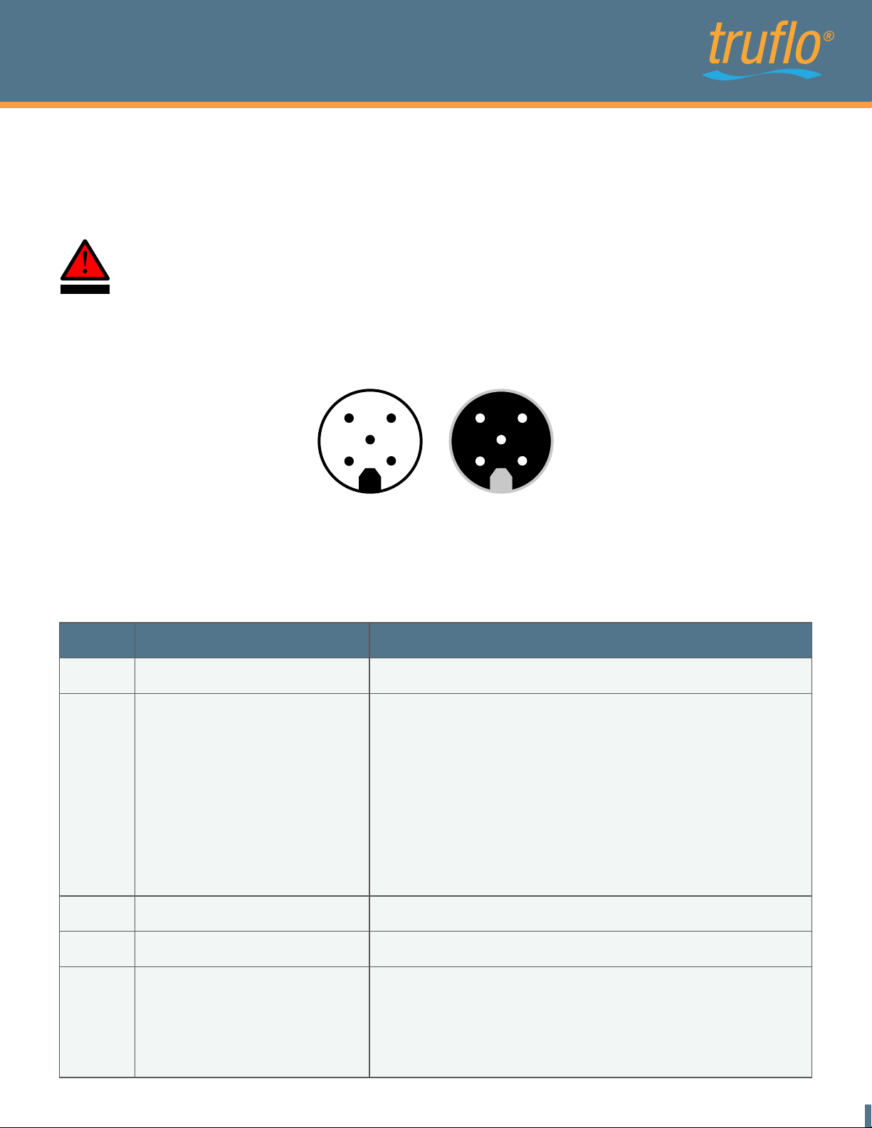
Fig. 3: Pin code: Connection plug / socket
Connector cable pin configuration defined by manufacturer
The outlets may be re-programmed for specific applications
Pin Function Description
1 L+ Power supply: 18...30 VDC
2 Pulse output O1 alternative:
1. Empty-pipe output
2. Dosing output
3. Upper or Lower Limit output
4. Negative flow
3 GND Ground : 0 V
Digital Output Q1
Freely adjustable ranging from 0.1 to 3000 ml/pulse in 0.1
l/pulse steps, npn-Transistor, max. load 30V/100mA.
m
Max. Voltage must be less than the supply voltage.
Configurable output of 0V or 24V when pipe is empty.
Configurable output of 0V or 24V
utput
Configurable o
lower limit
Configurable output of 0V or 24V when liquid flows in
negative direction
of 0V or 24V when reaching upper or
4 Communication Communication interface
5 Analog output QA 4….20mA ; 0….20mA
Example: 0L/min => 4mA
60L/min => 20mA
Empty pipe Alert => 3.5mA
(4-20mA depending on the configured limits)
Find Quality Products Online at: [email protected]
www.GlobalTestSupply.com
05
Page 8
ULTRAFLO 1000
PFA Teflon Ultrasonic Flow Meter
6
1
5
4
87 3
2
6
1
5
4
87 3
2
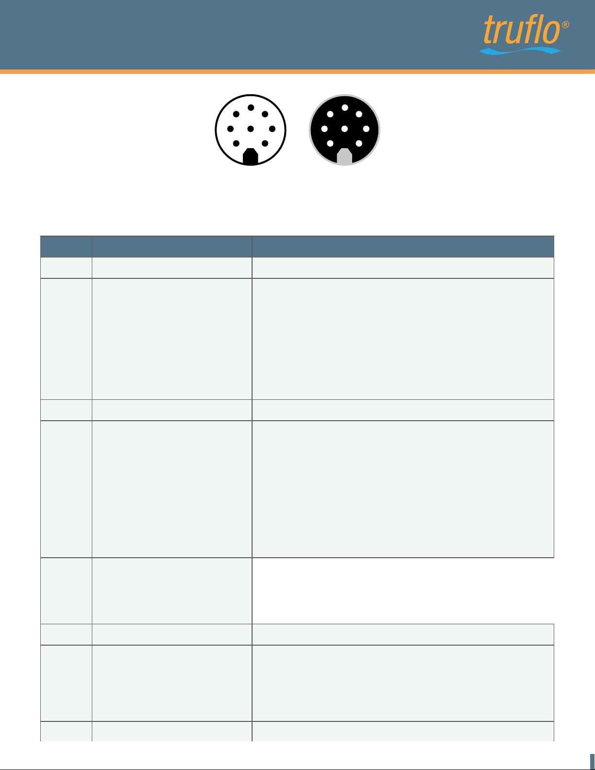
plug / socketFig. 4: Pin code: Connection
Connector cable pin configuration defined by manufacturer
The outlets may be re-programmed for specific applications.
Pin Function Description
1 L+ Power supply: 18...30 VDC
2 Pulse output O1 alternative:
1. Empty-pipe output
2. Dosing output
3. Upper or Lower Limit output
4. Negative flow
Digital Output Q1
Freely adjustable ranging from 0.1 to 3000 ml/pulse in 0.1 ml/pulse
npn-Transistor, max. load 30V/100mA. Max. Voltage must be
steps,
less than the supply voltage.
Configurable output of 0V or 24V when pipe is empty.
Configurable output of 0V or 24V
Configurable output of 0V or 24V when reaching upper or lower limit
utput
Configurable o
direction
of 0V or 24V when liquid flows in negative
3 GND
4
5 Analog Output QA 4….20mA ; 0….20mA
6 Communication Communication Interface
7
Digital output Q2 Functions:
1. Empty pipe output
2. Dosing output
3. Pulse output
4. Upper or Lower Limit output
5. Negative flow
Digital input I1
1. Dosing output
2. Set offset
3. Reset counter
4. Creeping flow off
Ground : 0 V
Digital output Q2
Configurable npn- or pnp-Transistor, max. Load 30V/ 100mA. Max.
Voltage must be less than the supply voltage.
Configurable output of 0V or 24V when pipe is empty.
Configurable output of 0V or 24V
Freely adjustable ranging from 0.1 to 3000 ml/pulse in 0.1 ml/pulse
steps.
utput
Configurable
limit.
Configurable output
direction.
Example: 0L/min => 4mA
60L/min => 20mA
Empty pipe Alert => 3.5mA
(4-20mA depending on the configured limits)
Digital input I1
Starts the dosage by a rising edge of 24V.
The Offset is set by a rising edge of 24V.
Reset of the counter by a rising edge of 24V.
Creeping suppression is deactivated as long as there are
24V at the input.
of 0V or 24V when flow reaches upper or lower
o
of 0V or 24V when liquid flows in negative
8 Shielding EMC safety
Find Quality Products Online at: [email protected]
www.GlobalTestSupply.com
06
Page 9
ULTRAFLO 1000
PFA Teflon Ultrasonic Flow Meter
Attention : Only operate the flowmeter Flowmeter within the operating limits stipulated
on the product label and the operating manual / data sheet. Use outside these
conditions lead to overloads which cause permanent damage.
3. Commissioning
NOTE : If Flowmeter is used for a fluid other than water the "basic trim" has to be carried
out during commissioning. Therefor the device has absolutely be filled with medium.
NOTICE
3.1 Operation
The basic trim can be done on the device display (alternatively Programmtool). During the
adjustment the medium may not flow as it affects the function
If Flowmeter is used as volume flowmeter for water or water-like liquids, it will not require on-site
calibration. Parameters for water are calibrated at the factory. Notwithstanding the Flowmeter may
also be supplied with customized settings. The coordination must be done at time of purchase
order.
NOTE : If necessary, e.g. if viscosity and/or speed of sound deviate significantly from
water, the pre-set parameters can be adjusted via Programmtool. It is always necessary to
adjust the manufacturer pre-set parameters when using the Flowmeter as a dosing device
NOTICE
according to section 3.2 (Dosing 1. Flowmeter as a dosing device). Adjusting the
manufacturer pre-set parameters requires Programmtool.
The following parameters may be changed to settings suitable for the individual
conditions:
Digital output Q1, function and behaviour
Digital output Q2*, function and behaviour
Pulse value
Analog output QA
Flow range, for which shall apply 4...20 mA
Creeping suppression
Dosing input I1*, function and behaviour
Optimization of measurement curve with up to 8 interpolation values (media matrix)
Described functions that are marked with * are not available for the 5-pin version. The available
functions of 5-pin version are described in the connection table on page 7. To change
configurations at Flowmeter a Programmtool is needed.
Find Quality Products Online at: [email protected]
www.GlobalTestSupply.com
07
Page 10
ULTRAFLO 1000
PFA Teflon Ultrasonic Flow Meter
3.2 Functionalities of flowmeter and default settings
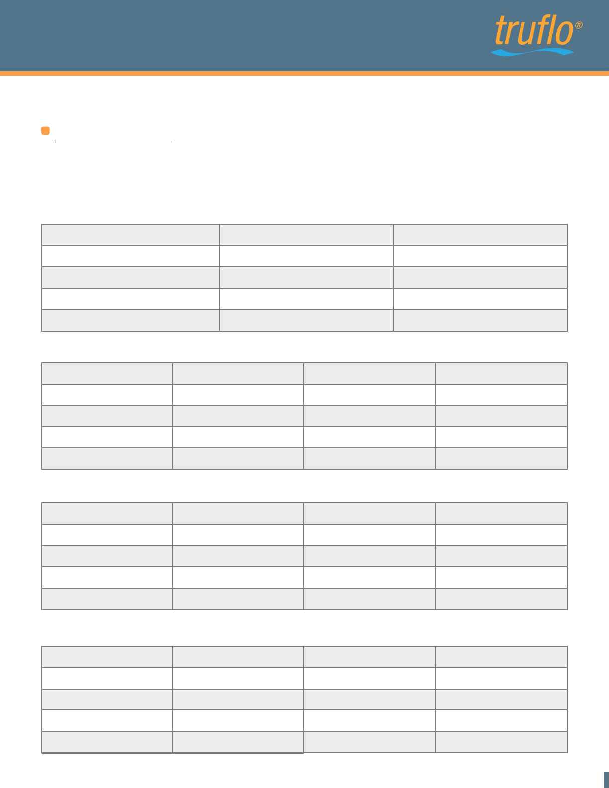
Digital outputs
All outputs switch over to high resistance when the supply is smaller than 18V. When overload or
short circuit is detected the digital outputs are switched off after 100µs for a period of 2s. When time
is up the outputs get applied again.
Empty pipe output
Empty pipe
0V normal closed High resistant
0V normal open 0V
24V normal closed High resistant
24V normal open 24V High resistant
Filled, no flow
0V
High resistant
24V
Pulse output
Empty pipe
0V normal closed 0V
0V normal open 0V
24V normal closed High resistance
24V normal open High resistance High resistance
Filled, no flow
0V
0V
High resistance
Filled, flow
0V Pulses
0V Pulses
24V Pulses
24V Pulses
Upper limit output
Below lower limit
Between the limits
Above upper limit
0V normal closed High resistance
0V normal open 0V
24V normal closed High resistance
24V normal open 24V 0V
High resistance
0V
High resistance
0V
High resistance
24V
High resistance
Lower limit output
Below lower limit
0V normal closed 0V
0V normal open High resistance
24V normal closed 24V
24V normal open High resistance 24V
Find Quality Products Online at: [email protected]
www.GlobalTestSupply.com
Betwenn the limits
High resistance
0V
High resistance
Above upper limit
High resistance
0V
High resistance
24V
08
Page 11
ULTRAFLO 1000
PFA Teflon Ultrasonic Flow Meter
Dosing output
Startup of device
0V normal closed High resistance
0V normal open High resistance
24V normal closed High resistance
24V normal open High resistance 24V
While dosing
High resistance
0V
High resistance
Before/after dosing
0V
High resistance
24V
High resistance
Important! When using the dosing function the output should not be configured as
normal closed!
If the dosing output is configured as normal closed the valve will stay open after the
Digital output Q1
Digital output Q1 may be used as pulse output, empty pipe detection, for switching dosing valve or
limit control. By using Programmtool the user can switch between npn and pnp-transistor logic. In
case of inductive load a diode has to be connected parallel to the coil.
Fig. 5: Connecting output Q1 to relay
Setting area : off, pulse output, empty pipe, dosing output, lower limit, upper limit, negative flow
Find Quality Products Online at: [email protected]
www.GlobalTestSupply.com
09
Page 12
ULTRAFLO 1000
PFA Teflon Ultrasonic Flow Meter
Digital output Q2*
Digital outputs 2 may be used as pulse output, empty pipe detection, for switching dosing valve,
limit control or flow direction control. See chapter 2.3 table connection
The npn or pnp logic can be selected. When the output is connected to an inductive consumer a
diode has to be installed parallel to the load.
Flowmeter via pnp, external counter e.g. PLC
Fig. 6: Connecting output Q2 to counter
Setting area : off, pulse output, empty pipe, dosing output, lower limit, upper limit, negative flow
Important! Inductive load on the digital outputs without an installed diode may cause
damage on the Flowmeter electronics. dosing batch.
Dosing function
Dosing can be determined in different ways :
1. Flowmeter as dosing device (dosing control via Flowmeter)
Flowmeter controls the complete dosing function. The dosing quantity (e.g. 400 ml) is pre-set in the
Flowmeter via Programmtool. Dosing starts, as soon as line start of dosing is wired to 24 V, e.g. via
a pushbutton. Flowmeter will now open the dosing valve via the output configured for it. When the
pre-set dosing quantity is reached, the dosing valve is closed via the above output. The second
output can be used independently for signalling empty pipe, limit control, pulse output or signalling
negative flow.
Find Quality Products Online at: [email protected]
www.GlobalTestSupply.com
10
Page 13
ULTRAFLO 1000
PFA Teflon Ultrasonic Flow Meter
2. Flowmeter as flowmeter (dosing control via dosing equipment)
The dosing equipment controls the entire dosing function. The dosing quantity is fixed in the dosing
equipment control during commissioning by pre-selecting the meter pulses. Dosing starts, when the
relevant pushbutton of the dosing equipment is pushed. The control will now open the dosing valve.
From now on Flowmeter will send a voltage pulse to the control for each volume unit that has flown
through (e.g. per 1ml). When the pre-selected pulse quantity is reached, the control closes the
dosing valve. In this case, output 1 is used to send out pulses, output 2 is independently usable for
empty pipe detection, limit control or signalling negative flow.
The customer has to provide an emergency stop and an overfilling stop to prevent
hazardous situations. Both functions must perform safety shut down of pumps and
WARNING!
closing of valves.
Pulse value
This section determines the output settings for pulsed outputs.
Choose configuration such as to neither exceed the maximum output frequency of the Flowmeter
(10kHz) nor the maximum input frequency of the control. If the maximum frequency is exceeded the
Flowmeter will not output pulses correctly.
Example
This Means
Setting Range
Default Setting
Flow
ml/s
1
2.0 ml/Pulse
a pulse is emitted every 2.0 ml.
0.1...3000.0 ml/Pulse, in 0.1 ml/Pulse steps
1.0 ml/Pulse
Pulse value
ml/Pulse
1
Frequency
Hz
1
Period
s
Duration of the Pulse
s ms
1
0.5
500
100
1000
100
0.5 10 0.05 20 1 50
0.1
10
1
100
10000
10
0.01
0.0001
0.1
0.005
0.00005
0.05
5
0.05
50
In the last case every 20 seconds, a pulse of 1 second duration is put out.
Find Quality Products Online at: [email protected]
www.GlobalTestSupply.com
11
Page 14
ULTRAFLO 1000
PFA Teflon Ultrasonic Flow Meter
Analog output QA
The analog output is available as current output 4-20mA or 0-20mA. This is selected with the
purchase order. As standard it comes with current output 4-20mA. It can also be switched off by
using Programmtool.
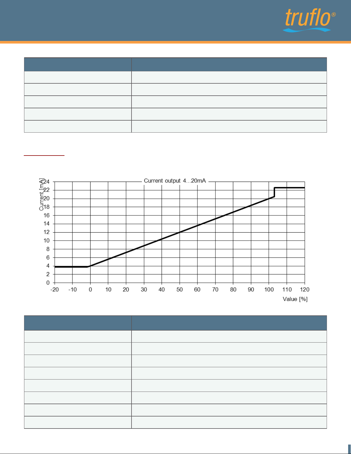
The current output ranges from 0 to 22.6mA measuring the flow rate or the condition of the flow
measurement.
The values here signify for 4-20mA configuration :
20 mA the upper limit of the relevant measurement
4 mA the lower limit of the relevant measurement
3.5 mA empty pipe
Upper and lower limit parameters can be set within the type-specific measurement of the device. By
default zero flow is set at 4 mA and the maximum flow is set at 20 mA
Setting range 0-20mA, 4-20mA, off
Output value Flow, Temperature
When current output is used, the load must not be higher than 500Ohm. A higher load
prevents the device from providing the maximum current of 22.6mA
Characteristic curves analog output
0 - 20mA
For the following graphic "min Range" is used for 0% and "max Range" is used for 100%.
Find Quality Products Online at: [email protected]
www.GlobalTestSupply.com
12
Page 15
ULTRAFLO 1000
PFA Teflon Ultrasonic Flow Meter
Value
Smaller 0%
0% (min Range)
Between 0% and 100%
100% (max Range)
Bigger 100%
Linear interpolation from 0 to 20 mA
Current [mA]
0
0
20
20
4 - 20mA
For the following graphic "min Range" is used for 0% and "max Range" is used for 100%.
Value
Empty pipe
Smaller -1.2%
Between -1.2% and 0%
0% (min Range)
Between 0% and 100%
100% (max Range)
Between 100% and 103%
Bigger 103%
Find Quality Products Online at: [email protected]
www.GlobalTestSupply.com
Linear interpolation from 3.8 to 4mA
Linear interpolation from 4 to 20mA
Linear interpolation from 20 to 20.5mA
Current [mA]
3.5
3.8
4
20
22.6
13
Page 16
ULTRAFLO 1000
PFA Teflon Ultrasonic Flow Meter
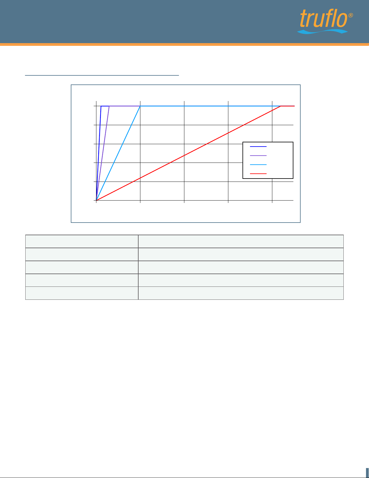
Filter options for analog output
Response time analog output
100
80
60
40
Value [%]
20
0
0 1 2 3 4
Filter
off
soft
medium
strong
Creeping suppression
Off
Soft
Medium
Strong
Time [s]
100%
16ms
0.3s
1s
4.2s
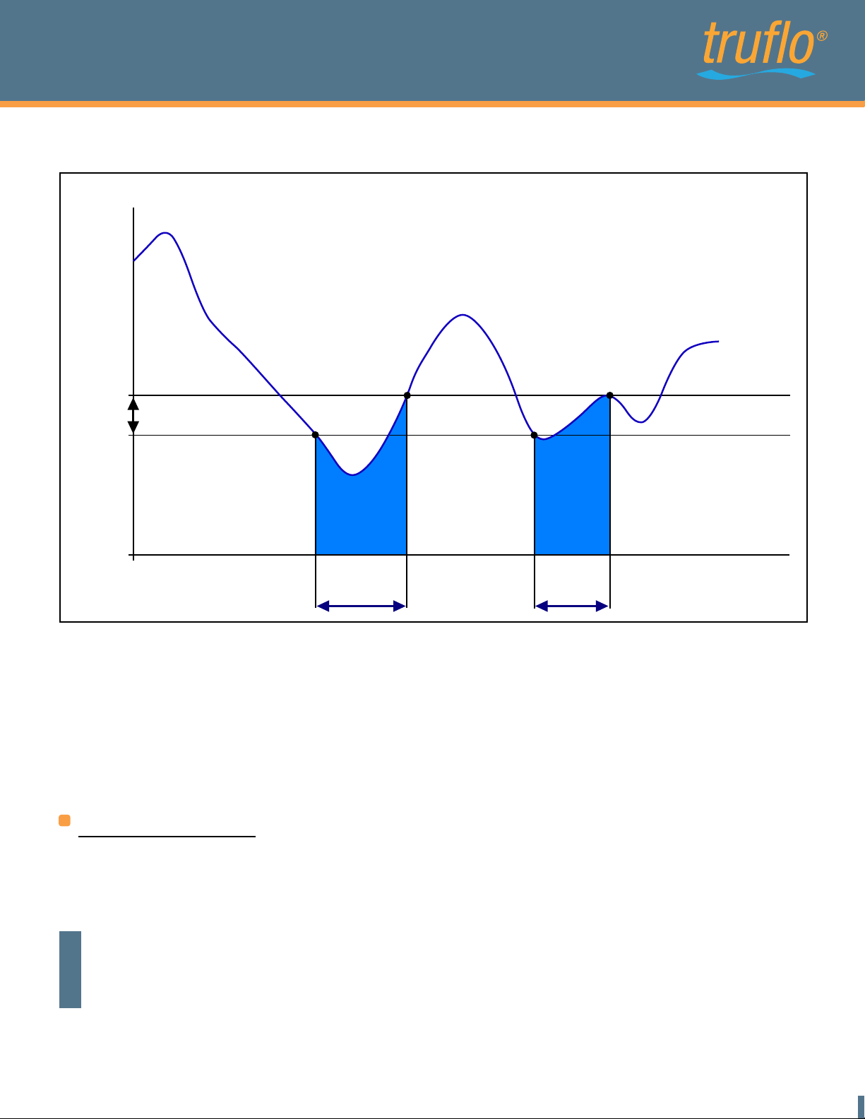
The creeping suppression excludes flow measurements that result from convection in a narrow
band around zero, even with a closed valve. At the factory, the creeping suppression is set at a
standard value in relation to the cross-section of the flowmeter.
There are higher tolerances below the standard default settings, see also section 5.2,
measurement errors!
Setting range : 0.0...20 l/min, in 0.006 l/min steps
Default settings : 0.09 l/min for DN7 / 3/8", LowFlow option 0.03l/min
0.3 l/min for DN10 / 1/2"
Find Quality Products Online at: [email protected]
0.9 l/min for DN15 / 3/4"
1.2 l/min for DN20 / 1"
www.GlobalTestSupply.com
14
Page 17
ULTRAFLO 1000
PFA Teflon Ultrasonic Flow Meter
The creeping suppression works with a hysteresis of -25%.
Flow [l/min]
1. Creeping Suppression switch on
2. Creeping Suppression switch off
1.2
1.05
0.9
0.75
2
2
0.6
-25%
1
1
0.45
0.3
0.15
0
Pulse/Analog output active inactive active inactive active
Fig. 7: Function of the creeping suppression illustrated with 0.6 l/min
Example :
Creeping suppression = 0.6 l/min
If the flow rate is lower than 0.45 l/min the pulse output/analog output becomes inactive.
If
the flow rate exceeds 0.6 l/min a pulse is output again and added to the totalizer.
Similarly, a value is transmitted to the analog output again.
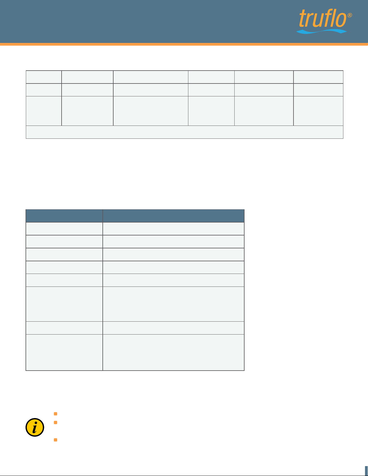
Digital input I1*
Flowmeter has a digital input that is programmable to following functions: dosing input, set offset,
creeping suppression inactive and reset counter. In order to start a dosing process, 24V DC power
is required. The status of the dosing parameters is modified with the Programmtool
NOTE : The dosing input is locked so that a re-start is not possible during a running dosing
process. After changing configurations via Programmtool a restart of the device is necessary
to activate the doing input function.
NOTICE
Find Quality Products Online at: [email protected]
www.GlobalTestSupply.com
15
Page 18
ULTRAFLO 1000
PFA Teflon Ultrasonic Flow Meter
Available input functions
0V
24V
Set offset Creeping flow off Dosing
- Rising edge:
0->24V
Set offset
State :
deactivating creeping
flow
Rising edge:
0->24V
start dosing
Reset counter off
Rising edge:
0->24
Vcounter is reset
-
-
Run only in stationary medium
The input function "Set Offset" may only be used when there is no flow through the meter. If an
offset trim is done while liquid flow is present an offset drift will cause measurement deviations. If
the Flowmeter shows an offset drift caused by a wrong offset setting, run the function "Set Offset"
or "Basic Trim" again with filled flow meter and no present flow.
3.3 Overview of default settings
Function
Digital output Q1
Digital output Q2*
Default settings
Pulse output as 24V normal open
Empty pipe detection as 24V normal open
Digital input I1*
Analog output QA
Current output
Measuring range
Pulse value
Creeping suppression
No function assigned
Current output
4-20mA
20mA -> 6 l/min for 3/8"
24 l/min for 1/2"
60 l/min for 3/4"
120 l/min for 1"
1 ml/pulse
0.09 l/min for 3/8", 0.03l/min LowFlow
0.3 l/min for 1/2"
0.9 l/min for 3/4"
1.2 l/min for 1"
3.4 General Information
Please check the following before powering the flowmeter for the first time:
Check the electrical connections and cable allocations
Check the installation position of the flowmeter. Are the direction of the arrow on the
name plate and the actual flow direction in the pipe congruent?
Is the measurement pipe completely filled with fluid?
Find Quality Products Online at: [email protected]
www.GlobalTestSupply.com
16
Page 19
ULTRAFLO 1000
PFA Teflon Ultrasonic Flow Meter
When everything has been checked, switch on power. After 30 minutes with power running the
measuring device reaches the maximum accuracy.
Now, Flowmeter is operational!
4. Exchange of Measuring Device
Switch off power before disconnecting the electrical connections!
Wiring installation, disassembly and removal must be performed by qualified persons
experienced and knowledgeable about electrical work.
Serious injury or death from electric shock may occur if wiring, installation,
WARNING!
d
isassembly or remove of wires is performed while electrical power is energized
Please note that after replacing the flowmeter
a) the programming of the previous flowmeter should be saved and copied on the new flowmeter
b) when using the dosing function, set a quantity
If the device requires a configuration change, the display and programming unit Programmtool is
required.
Repair, Hazardous Substances
Before sending the flowmeter Flowmeter for repair, the following precautions must be taken:
Clean all process chemicals from the device. Fully rinse the flow path. Please
pay close attention to the process fittings. All media must be removed before
returning. This is particularly important, if the medium to be measured is health
WARNING!
Devices judged to be insufficiently cleaned will be returned to sender. No inspection of device will
be done until proper cleaning is completed by user.
Costs due to inadequate cleaning of the instrument for possible disposal or injury (burns, etc.) will
be charged to the sender of the meter into account.
hazardous.
With the flowmeter send a detailed report describing the failure, the application
and the physical-chemical properties of the medium parameters. (e.g. a
WARNING!
In order to be able to process your repair order quickly and smoothly it is important that you provide
a technical contact person including phone and fax number as well as e-mail address.
Find Quality Products Online at: [email protected]
decontamination declaration).
www.GlobalTestSupply.com
17
Page 20
ULTRAFLO 1000
PFA Teflon Ultrasonic Flow Meter
5. Technical specifications
5.1 Dimensions and weight
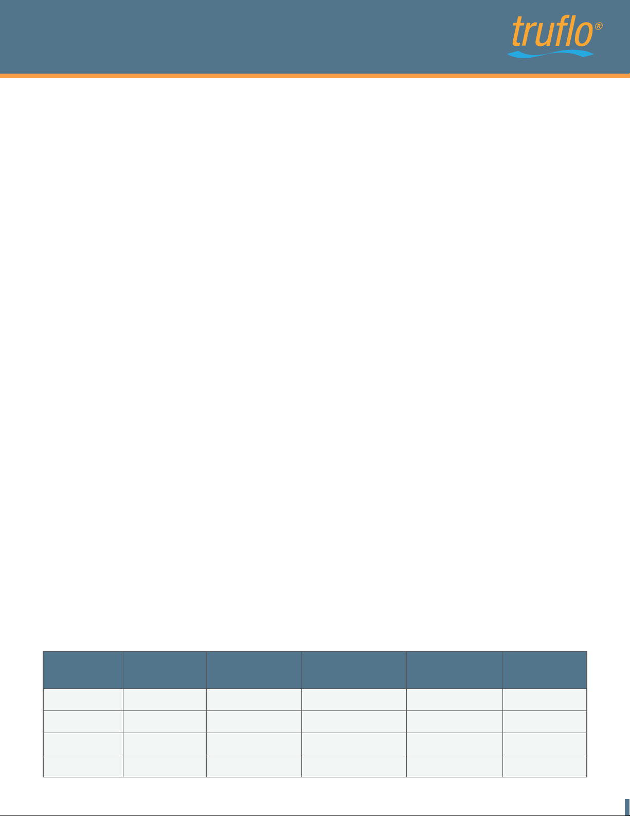
Nominal
width
DN7 3/8"
DN10 1/2"
DN15 3/4"
DN20 1" 251.0 120.0 91.5 25 1.3
Find Quality Products Online at: [email protected]
Length A
[mm]
218.0
219.5
227.0
Width B
[mm]
120.0
120.0
120.0
Height C
[mm]
79.0
79.0
82.0
Height of axis D
www.GlobalTestSupply.com
[mm]
16
16
19
Weight
[kg]
1.1
1.1
1.1
18
Page 21
ULTRAFLO 1000
PFA Teflon Ultrasonic Flow Meter
5.2 Technical Specifications
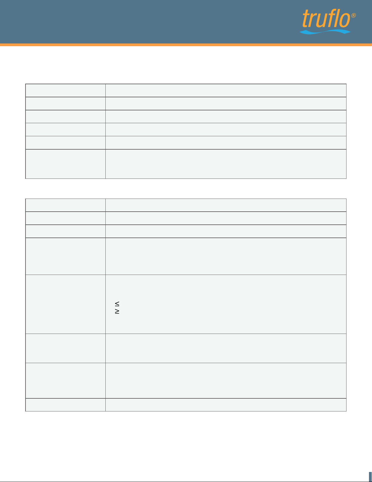
Housing
DN7 - 3/8", DN10 - 1/2",DN15 - 3/4", DN20 - 1"Nominal diameters
Connection Flare
Medium temperature 0...+80°C
Protection class IP 65
Pressure nominal PN 6
Material All parts in contact with medium made of PFA
Flare nut : PVDF or PFA
Electronics housing : PP
Electronics
18...30VDC, 3.6WPower supply
Connection plug 5 pins, plug 8 pins, 10-wire Teflon cable (5m)
Ambient temperature -20....+60°C
Current output QA 0/4...20 mA
Lower- and upper limit adjustable,
Ground connected to supply ground
Error Signal according to NAMUR NE43
Digital output Q1 /2 via transistor npn- and pnp-logic
max. 30V/100mA
output voltage according to DIN 19240:
5V means LOW
12V means HIGH
Short cut resistant
Frequency 0....10kHz
Data interface ± 2% of reading ± 3 mm/s
Option: ± 1% of reading ± 3 mm/s
Reference conditions (VDE/VDI 2642)
Measuring ranges* 3/8": 0.09…6 l/min, 0.03…6 l/min Low Flow
1/2": 0.3…24 l/min
3/4": 0.9…60 l/min
1" : 1.2…120 l/min
Repeatability: 0.5%
The measuring system Flowmeter meets the general EMC immunity requirements according to CE,
EN 61000-6-3, EN 61000-4-2, EN 61000-4-3, EN 61000-4-4, EN 61000-4-5, EN 61000-4-6. It is in
conformity with the requirements of the EC directives and has the CE label.
*The flow range limits correspond to a flow speed of ~3m/s with Flowmeter of size 3/8", ~6m/s with
Flowmeter of sizes ½", ¾" und 1"
Find Quality Products Online at: [email protected]
www.GlobalTestSupply.com
19
Page 22
ULTRAFLO 1000
PFA Teflon Ultrasonic Flow Meter
Behavior of the Temperature Sensor
The integrated temperature sensor has no direct contact to the liquid and is used to calculate the
expansion of the housing. The environment temperature greatly influences the actual temperature
of the temperature sensor. The response time of temperature changes relates to the mounting
position of the temperature sensor inside the housing.
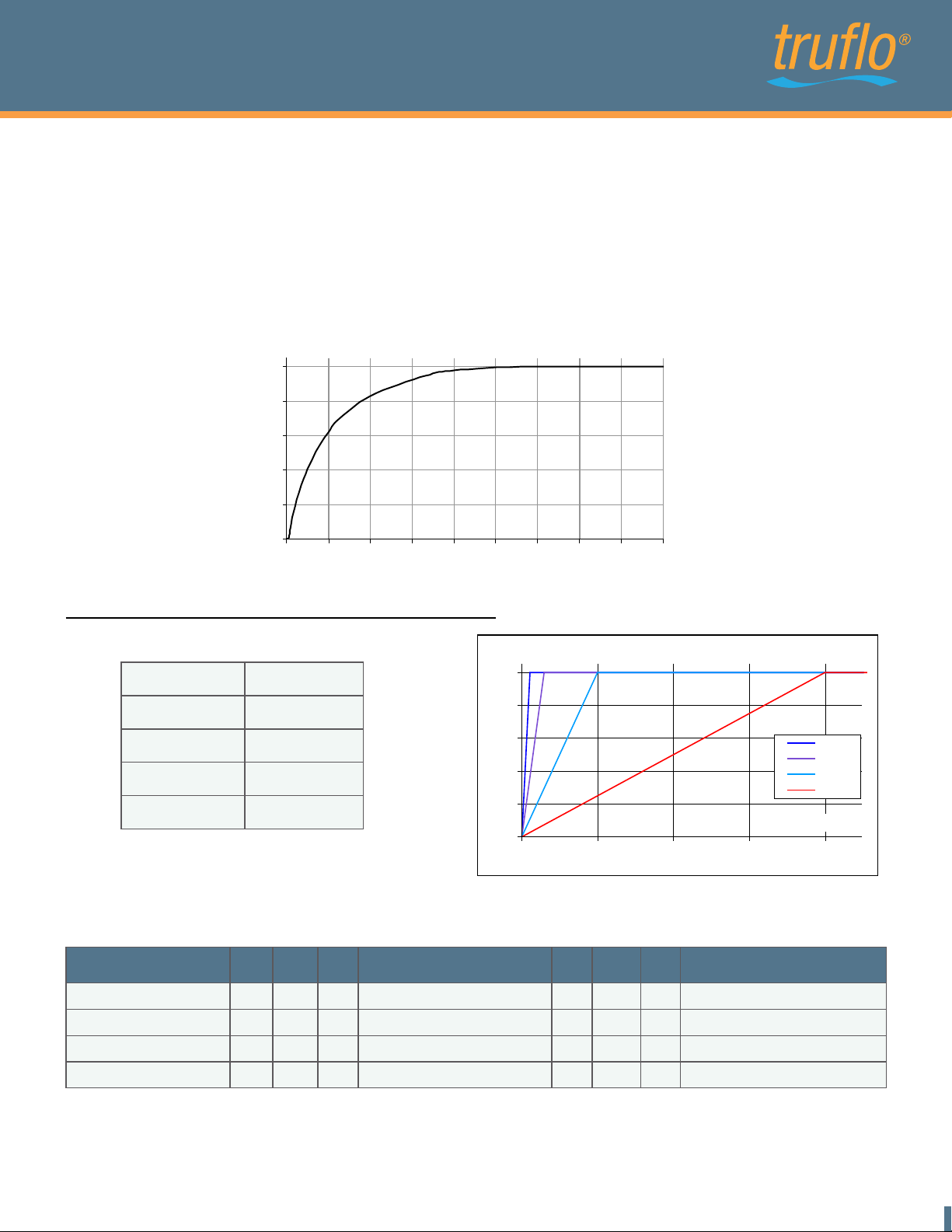
Step-Response Time
Step-response time after a significant temperature change. (Filter "Off")
100
80
60
Temperature [%]
40
20
0
0 5 10 15 20 25 30 35 40 45
Step-response time
Filter Configurations for Temperature Sensor
Filter
Off
Soft
Medium
Strong 4min
100%
1s
16s
1min
Step-response with filter
100
80
60
40
Value [%]
20
0
0 1 2 3 4
Time [min]
Off
Soft
Medium
Strong
Time [s]
Influence of the environment temperature
In the table below some examples of the temperature influence are shown.
Liquid Temp
40
40
40
60
X
0.7
X
X
X
X
0.7
0.7
0.7
0.7
+
Environment temp.
+
+
+
20°C
20°C
20°C
0.3
X
0.3
X
0.3
X
0.3
X
0.3
X
=
=
=
=
=
Measured temp.
34°C
37°C
40°C
48°C+ 20°C
In case of an error :
In case of a short circuit of the temperature sensor -50°C are shown.
In case of a cable brake between temperature sensor and electronic -30°C are shown.
Find Quality Products Online at: [email protected]
www.GlobalTestSupply.com
20
 Loading...