

Page 1
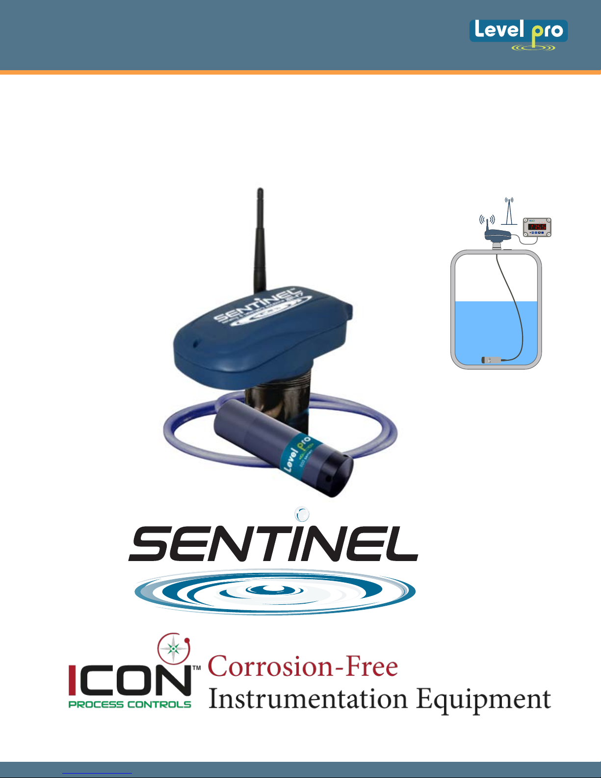
Sentinel Series | Telemetry
Tank | Sump Liquid Level Monitoring
INSTRUCTION MANUAL
WIRELESS REMOTE TANK UNIT
AL R1 R2
ESC
ENTER
MENU
Read carefully the instructions published in this manual before the first use of the level meters. Keep the manual
at a safe place. The manufacturer reserves the right to implement changes without prior notice.
TM
Page 2
Sentinel Series | Telemetry
Tank | Sump Liquid Level Monitoring
FCC STATEMENT
This device complies with Part 15 of the FCC Rules. Operation is subject to the following two
conditions:
(1)This device must not be allowed to cause harmful interference
(2)This device must accept any interference that may cause undesired operation.
Sentinel Series Introduction
Overview
The Sentinel Series is a wireless communication device that provides quick and easy access to
remote information such as storage tank inventory. Intended for supplier-managed inventory
programs, the Sentinel utilizes the latest internet and cellular technology to provide instant access
to inventory information around the globe. Coupled with the Sentinel information web site, the
Sentinel can provide a tremendous advantage over conventional systems for inventory
management, asset control, or information exchange.
For Your Safety
This equipment contains a cellular radio which transmits at several times the power of a hand-held
cellular phone. While it has been tested to comply with applicable FCC regulations and is approved
for use in nonresidential applications, it may still interfere with other electronic equipment.
Therefore its use in certain situations is restricted. Read these installation and operation instructions
carefully. Failure to follow these instructions may be dangerous or illegal. Only qualified service
personnel must install or repair this equipment.
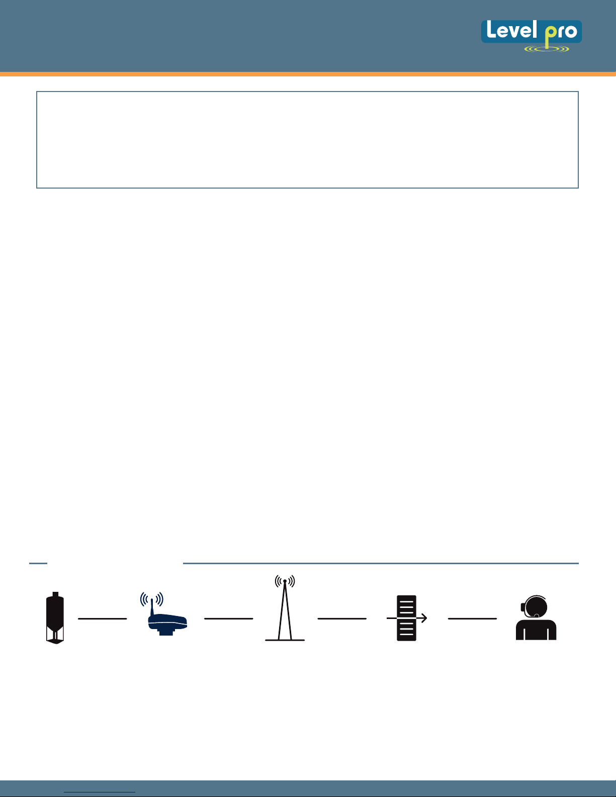
HOW IT WORKS
TANK / SUMP SENTINEL CELLULAR NETWORK SENTINEL 247 ONLINE INVENTORY MANAGER
Fig 1
01
Page 3

Sentinel Series | Telemetry
Tank | Sump Liquid Level Monitoring
Transfer of Data
The Sentinel communicates to the cloud based da
called GSM Short Message Service. This technology allows the unit to transmit digital data to the
data center using the existing network of GSM cellular towers deployed throughout North America.
In order to transmit a data packet, the local GSM cellular carrier must provide SMS (Short Message
Service). Once the data is at the cloud based data center, it may be viewed over the INTERNET
using a standard web browser (i.e. Microsoft Internet Explorer), downloaded to applications such
as Microsoft Excel, or it may be used to trigger events such as an e-mail or text to the inventory
manager or service representative. To access the data provided by the Sentinel unit, a current
monitoring service agreement with Sentinel is required.
Product Highlights
• No telephone line is required for communication.
• No external power source is required.
• Fast, simple installation.
• Flexible sensing technology.
• Fixed monitor
• Readily available r
• Unlimited applications.
ing costs.
eplacement batteries
.
ta center using a wireless cellular technology
INSTALLATION
Safety Precautions
The Sentinel uses Radio Frequency (RF) waves for communication to the nearest cellular tower and
can transmit at several times the power of a hand-held cellular phone.
In general, if you can place a cellular telephone call in the location where you wish to install the unit,
then the Sentinel should be able to communicate properly.
However, because of the inherent characteristics of RF communications, there are certain guidelines
that should be followed when positioning the unit
DO NOT install the Sentinel where hazardous vapors are present.
WARNING!
DO NOT use the Sentinel where blasting is in progress
sensitive electronic components. Be sure to discharge yourself by touching a grounded metal
object before
opening the unit. The unit should be installed in an area free from overhanging metal
structures, large obstructions, or equipment which could generate RF or electrical interference.
DO NOT install the unit below ground level unless provisions are made for an external
antenna. Service may be limited in areas that do not have GSM cellular coverage and support
SMS (Short Message Service). If the unit is installed in an area with poor signal strength, an
external antenna may be required for reliable performance. If you have doubt about the suitability
of a particular location for the Sentinel, or are having difficulty transmitting, please see Sections
3-2 and 3-3. If an external antenna is required, several optional antennas are available. Please
contact Sentinel Customer Service to determine your exact needs
Electrostatic discharge can damage
02
Page 4
Sentinel Series | Telemetry
Tank | Sump Liquid Level Monitoring
Initial Inspection
When you receive the Sentinel unit, thoroughly inspect it for any damage, which may have
occurred during shipping. If there is any damage to the Sentinel, contact the shipping company
as soon as possible.
Locate the packing checklist in the shipping container. Check for any missing items before
you begin installation of the Sentinel.
Note: The Sentinel is shipped with the antenna disconnected. It is located in a separate
area within the shipping carton. Verify that the antenna is present before proceeding.
Mounting a 100 Series Submersible Level Sensor
Differential Pressure Sentinels operate by measuring the pressure (weight) of the liquid the sensor is
submerged into. This pressure is proportional to the density of the liquid.
The opening on the end of the sensor contains an exposed diaphragm which responds to changes
in liquid pressure as the tank is filled or emptied with product. This measured pressure is compared
against atmospheric pressure, and is converted to a readable signal by a microprocessor in the
Sentinel. Please note that the sensor and sensor cable must be clean when installed, to avoid
contamination of the contents of the tank. These tanks are inspected for product contamination,
and the Sentinel installation cannot compromise the product in the tank.
Care must be taken before and during installation to not strike the sensor against any stationary
surface. This can frequently occur during installation of the probe into the tank. Shock may damage
the probe causing it to fail prematurely.
DO NOT install the sensor in a liquid that is susceptible to freezing or at the bottom
with water in it that may freeze. If the liquid freezes, it will damage the probe which will not be
covered under warranty.
WARNING!
DO NOT install the sensor in a tank with a mechanical agitator
DO NOT drop or strike the sensor against a solid object. This may damage the sensor or cause
a shift in the output of the probe.
of a tank
DO NOT kink the probe cable. This could restrict the breather tube in the cable and cause
fluctuating readings.
DO NOT install the sensor where sludge or sediment can clog the probe opening. If necessary,
suspend the sensor above the maximum level of the sediment.
DO NOT use the Sentinel housing to screw the unit into the tank. Use only the wrench flats on
the bottom fitting.
03
Page 5
Sentinel Series | Telemetry
Tank | Sump Liquid Level Monitoring
Mounting an Sentinel Unit
The Sentinel Unit comes standard with a 3/4 inch female NPT connection on the bottom of the
housing for direct connection into standard instrumentation. The wiring will pass thru this 3/4
inch connection to the terminal strip.
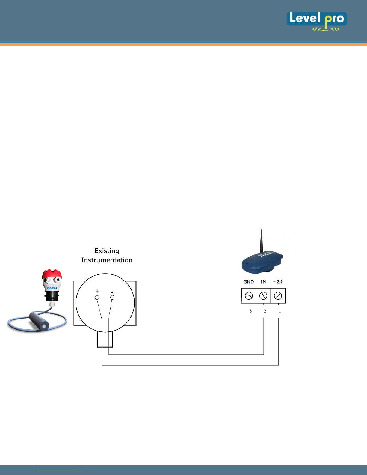
Wiring the Current Loop
The wiring for the current loop passes through the bottom of the housing, thru the hole in
the electronics board, and connects at terminal strip J3. Refer to Figure 8.
Sentinel Unit Providing Current Loop
In this scenario, the Sentinel is providing the power for the sensor thru the current loop.
Typically the Sentinel is mounted directly to the sensor using a 3/4-inch NPT connection. The
Sentinel can supply no more than 24 VDC to the sensor. Please note the return wire is connected to
JP3 – 2 (IN), and not to GND. The electronics of the Sentinel unit route the return to ground
internally.
LP100
Junction Box
Sentinel
100 Series
Fig 2
Providing Current Loop Power
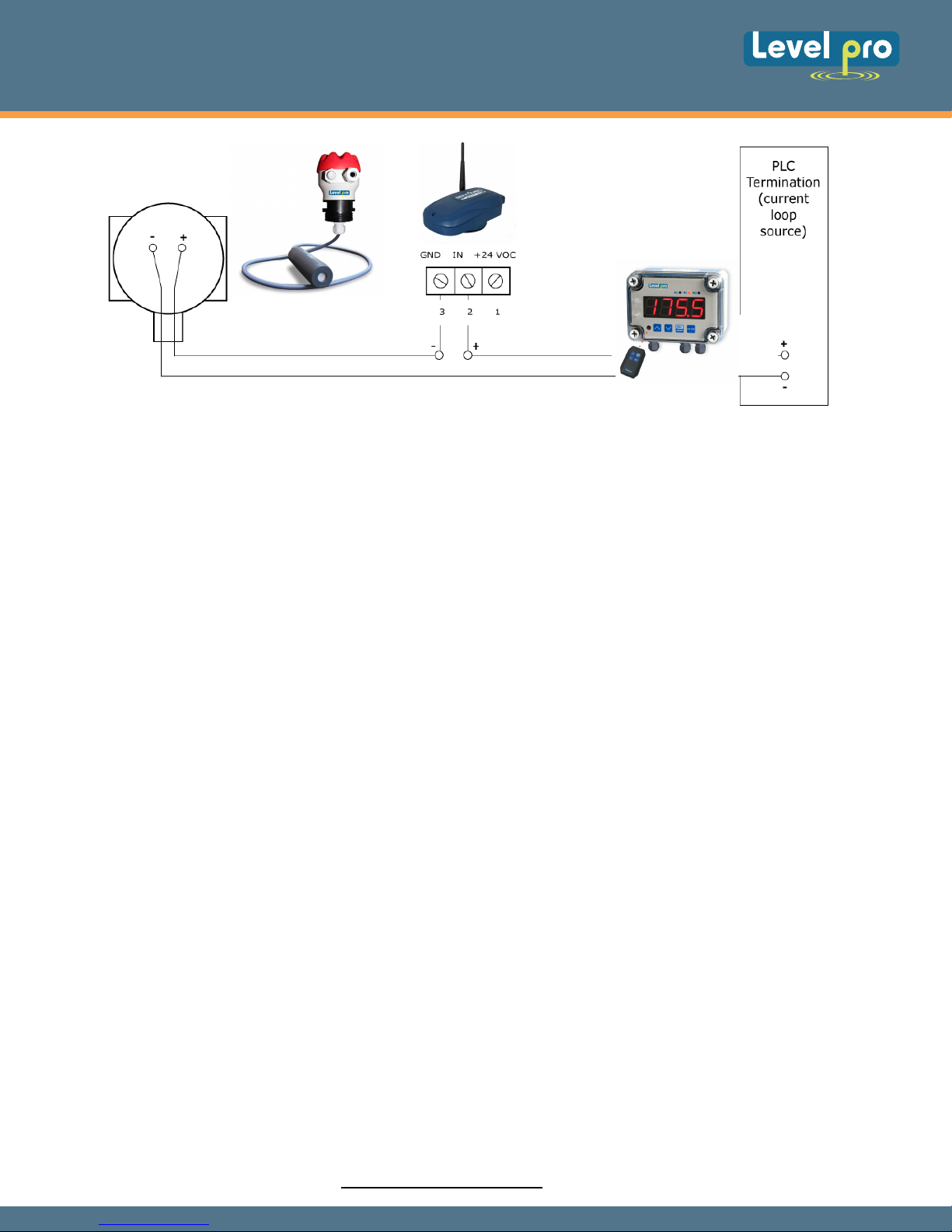
Sentinal Unit Placed in Series with Existing Current Loop
Power (Between +24VDC and existing instrumentation)
In this scenario, the Sentinel is wired into an existing, established current loop on the
positive side (between the current loop source and the instrumentation).
04
Page 6
Sentinel Series | Telemetry
Tank | Sump Liquid Level Monitoring
LP100 Junction Box
100 Series
Sentinel Installed in an Existing Current Loop
4 Unit Activation
4.1 Verifying GSM Signal Strength
During installation, you can determine your GSM signal suitability by operating a GSM
cellular phone and confirming its operation capability by placing a call.ti
4.3 Establishing Communication
Sentinel
TVL Series
Display
Fig 3
Once all tank preparation has been completed, the Sentinel is properly mounted to the
tank, the GSM SMS (Short Message Service) is available, signal strength has been
verified, and the number of callouts per day has been properly set, it is now time to
establish communications with the Icon Process Controls Data Center.
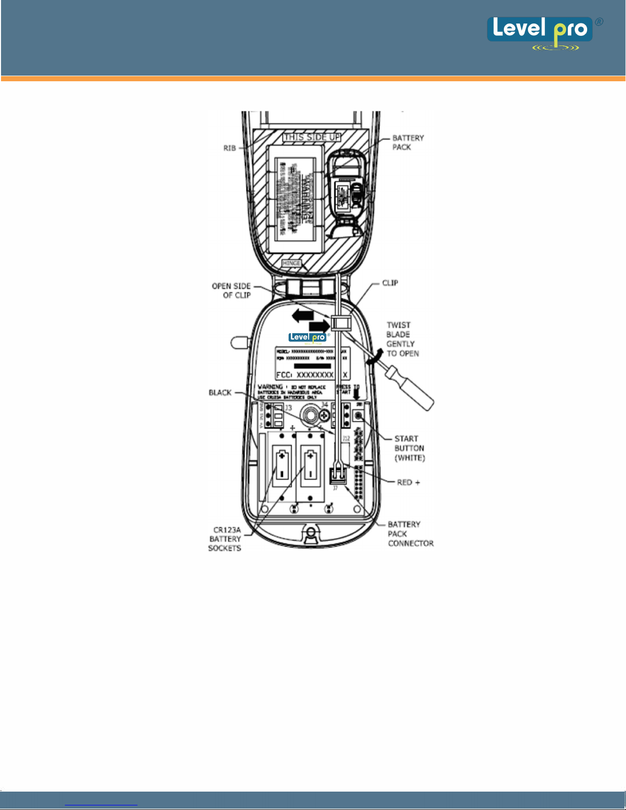
1) Open the top cover of the Sentinel opened by loosening the screw at the front of the lid
using a 3/16” flat screwdriver. Insert the two batteries into the battery holders at the insidefront of the housing and connect the optional extended life battery pack if present (J7). Refer
to Figure 4 ( Next Page )
2) Verify that the Prophet’s antenna is pointing straight up.
3) Press the white button on the right side of the unit. A green LED
inside front of the housing.
4) The green LED will flash fast (half second ON, half second OFF).
5) Once a cellular network is found, the green LED will flash slow (one second ON, one
second OFF).
6) The green LED will go to solid ON for about 60 seconds while the unit is
transmitting data to the Levelpro® Data Center.
7) After a successful transmission, the green LED will flash and then go out. The
Sentinel is now in sleep mode, and will remain in sleep mode until the next scheduled
transmission time or until the white button is pressed again.
will light up at the
8) If the data transmission was not successful, a red LED will light and the green LED will
flash an error code. Refer to Section 8-1 of this manual for information on the error codes.
9) Contact Icon Process Controls Customer Service at 1-905.469.9283 to verify a
successful data transmission, and to verify tank information.
10) Secure the top cover. Do not over tighten the screw.
05
Page 7
Sentinel Series | Telemetry
Tank | Sump Liquid Level Monitoring
Fig 4
Page 8

Sentinel Series | Telemetry
Tank | Sump Liquid Level Monitoring
After communication has been established, and the tank information has been given to
the Levelpro Monitoring Center, the Sentinel will continue to transmit data based upon
the number of call-outs per day set.
This tank data can be accessed through the INTERNET
The real power behind the Levelpro® Inventory management system is the
web site. On this web site, you may view the current level and status of your devices
using a standard web browser download your historical data to applications such as
Microsoft Excel®, or set up alarm levels to automatically trigger events such as an e-mail
or page to a local service or sales representative. The Levelpro web site is a secure web
site which utilizes the latest in INTERNET encryption technology to ensure that
your data stays confidential. It is constantly being upgraded and new
features are being added periodically. To obtain the latest details on how to use the
new features of the web site, follow the links to the help section of the web site.
4.2 Amplifying a Weak Carrier Signal
If the signal strength is weak as indicated by Error Code 7 in Section 7.1, or if data
transmissions are intermittent, an external antenna can be used as a replacement
to the small antenna supplied with the Sentinel. The external antenna connects
directly to a Sentinel with no adapter connector necessary, thereby
improving the antenna’s performance. Please contact Icon Process Controls
Customer Service at 905.469.9283 for the available and supported external
antenna options. The following outlines the most common external antenna
installation steps.
1) Position the external antenna at a location within cable reach of the Sentinel's
installation and attach it to the Sentinel replacing the small antenna.
2) Holding the external antenna at the same location where the Sentinel is installed
(typically the top of the tank).
3) Test unit by initiating a data transmission
the Error Code output in Section 7.1.
4) If the above test doesn’t produce any Error Codes as defined in Section 7.1, proceed
to the next step. If the Error Code 4, Error Code 7 or Error Code 8 still appears, see
if the external antenna can be moved to a different location, possibly outside the
building or higher into the buildings roof.
with the external antenna, and observing
5) Secure the external antenna using either the magnetic base, or the clamp base
supplied with the antenna.
Page 9

Sentinel Series | Telemetry
Tank | Sump Liquid Level Monitoring
5 Accessing the Levelpro Web site
The web site for accessing the tank data may be accessed from any computer with
internet access by going to the following URL:
`
This will bring you to the Levelpro Log on page.
view your data on the web you must first have a Logon and Password. A Log on
To
and Password will be provided to you or to your representative when the service
agreement with Icon Process Controls is finalized. If you have forgotten your logon or
password or need a new one, please contact the Levelpro Customer Service at
905.469.9283
Once a valid log on and password have been entered, you may select which tanks to
view. Tanks may be viewed by geographical location, product type, region, etc. Once
the tank levels are viewed, detailed information for each tank may be viewed,
edited, or the historical data for the tank may be viewed.
When a unit is sold by Icon Process Controls, a default tank entry is set up on the web
site and it is assigned to the log on. When the unit is installed, the pertinent
information will need to be set up on the web site by the customer. This includes: Tank
Name, Product type, Tank Location, Contact information, etc.
Page 10

Sentinel Series | Telemetry
Tank | Sump Liquid Level Monitoring
6 Sentinel Specifications
Performance Specifications:
Output Voltage Nominally 24V ± 5%
Output Current Rated from 0 – 24 mA
Load Regulation 0.5% from a 24 mA load
Ripple 50 mV Peak-to-Peak
Output Short Circuit Protection Output is current limited to 24 mA
Accuracy ± 1% of Span
Hardware Specifications:
Differential Pressure Sensor SS316; 1 inch (25 mm) OD x 3 inch (76 mm) length;
0-30 psi (0-2.1 kg/cm2) operating range for 34 ft (10.3
meter) cable; 7.5 psi (0-0.53 kg/cm2) for 17 ft (5.1
meter) cable. 2” Polypropylene NPT fitting.
Ultrasonic Sensor PVDF Kynar construction exposed to wetted portion of
the tank.
Housing NEMA 4X; weatherproof; UL approved (UL94HB);
glass-filled nylon
Area Classification General Purpose environment
Unit Gross Weight With Ultrasonic Level Sensor: 2.0 lbs (0.91 kg)
With 7.5 psi range Submersible Differential Pressure
Sensor: 2.1 lbs (0.95 kg)
With 15 psi range Submersible Differential Pressure
Sensor: 2.6 lbs (1.18 kg)
Battery:
Type Three Replaceable Lithium-Ion Batteries (CR-123A)
Expected Battery Life One call out per day – up to 3 years
Environment:
Storage Temperature Range -40˚F to 185˚F (-40˚C to 85˚C)
Operating Temperature Range -22˚F to 167˚F (-30˚C to 75˚C)
6.1 Antenna Connector
Type Standard SMA
Frequency Bands 850 (824 – 894) MHz
Three call outs per day – up to 1 year
1900 (1850 – 1990) MHz
Page 11
Sentinel Series | Telemetry
Tank | Sump Liquid Level Monitoring
7 Servicing and Troubleshooting
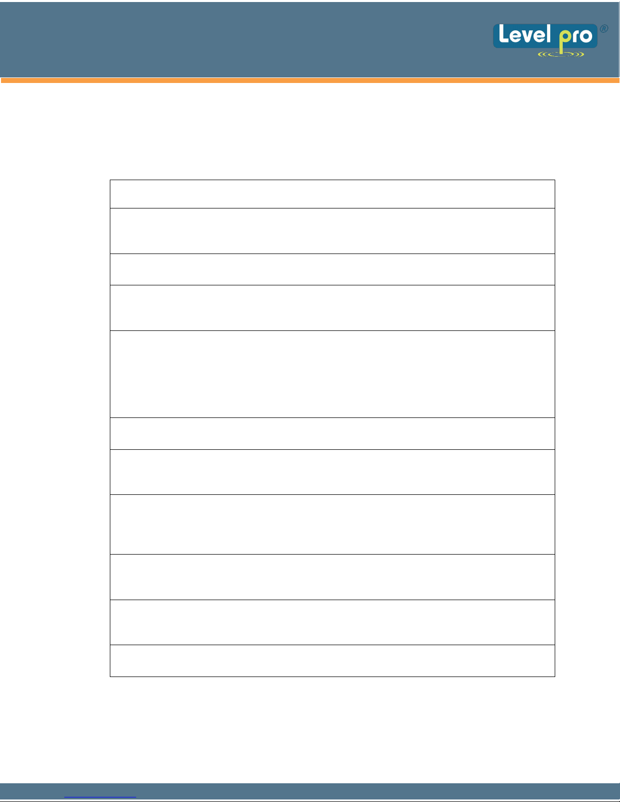
7.1 Error Codes
If the data transmission was not successful from a Sentinel, a red LED will light and
the green LED will flash an error code.
Number of
Red Flashes Error Code Description
Internal Hardware Error: Sentinel could not initialize properly
1
due to an internal hardware error. If this problem continues,
replace the Sentinel unit.
2
3
4
5
6
7
Low Battery Voltage: Sentinel could not transmit due to a low
battery voltage. Replace the batteries and re-try a data transmission.
Radio Error: The Prophet’s wireless transmitter did not power
on properly. Re-try a data transmission. If this problem
continues, replace the Sentinel unit.
Cellular Service Error: The unit did not detect cellular service.
Verify that there is service in the area using the technique in Section
4.2 or check GSM coverage information on Web Sites in Section 4.6.
Ensure that the antenna is tightly connected to the unit and is vertical.
If still not successful, contact Icon Process Controls Customer
Service for confirmation of data channel availability.
Cellular Busy Error: The Sentinel could not transmit because
the cellular network is busy. Re-try data transmission.
Radio Respond Error: The Prophet’s wireless transmitter did not
respond to the command to transmit data. Re-try a data
transmission. If this problem continues, replace the Sentinel unit.
Low RSSI Error: The data transmission failed due to low signal
strength Error Code 7 in Section 7.1. Apply the technique indicated in
Section 4.3 to establish the best location for an external antenna to
improve the signal strength.
Failed Transmission Error: The data transmission failed. Insert new
8
9
10
batteries into the unit and re-try a data transmission. If this
problem continues, contact Icon Process Controls Customer Service.
Radio Error: The Prophet’s wireless transmitter did not initialize
properly. Re-try the data transmission. If this problem continues,
replace the Sentinel unit.
Memory Error: The Prophet’s memory has been corrupted. If
this problem continues, replace the Sentinel unit.
Page 12
Sentinel Series | Telemetry
Tank | Sump Liquid Level Monitoring
7.2 Battery Replacement - Resetting Battery Cloud Based Indication
The Sentinel operates on 2 CR-123A disposable lithium batteries and an extended
battery pack. The Sentinel estimates the remaining battery life using a sophisticated
algorithm based on the battery voltage and temperature, cellular signal strength and
the number of transmissions and retries that the unit has made. This estimate is transmitted
to the Levelpro monitoring center and displayed on the internet. The procedure below
outlines the steps necessary to change dead batteries.
1. Carefully loosen the captive screw at the front of the housing using a 3/16” flat
screwdriver, then lift the top cover to expose the electronics and batteries.
2. Remove the batteries from the battery holder
3. Press the white button six (6) times; wait 30 seconds to allow the Sentinel memory to
initialize. Install new batteries, making sure the positive end of each battery is
towards the back of the electronics.
4. Properly dispose of all expired batteries and pack. Never mix fresh batteries with
partially or fully expired batteries.
5. START the Sentinel: Before closing and securing the
pushbutton and verify the green LED begins to flash.
6. Call your customer support representative to verify operation (905.469.9283 via the
Tank Data web portal or update the battery configuration setting from the Sentinel
Tank Setup page. See detailed instructions for further information.
7. Close the monitor lid. Ensure the gasket seal is secure and flush in the groove of the
enclosure base. Failure to do so may allow moisture to enter the enclosure and
damage the electronics.
8. Tighten the locking screw using a small flat blade screwdriver.
9. Congratulations
When purchasing individual batteries, always use model CR123A.
Never use batteries labeled CR123.
you have successfully replaced the batteries.
lid, press the white START
Page 13

Sentinel Series | Telemetry
Tank | Sump Liquid Level Monitoring
7
.3 Troubleshooting
Nothing happens when the Start switch is pressed.
9 Remove all of the batteries. Wait 30 seconds to initialize the
then reinsert the batteries. If the green LED does not come on when the switch is
pressed, replace the batteries with new ones.
Sentinel memory and
Unit cannot transmit to data center.
9 Verify that the RSSI is greater than 20.
9 Verify
carrier preference setting.
9 Check for interfering
9 Reposition the unit if possible.
9 Check that the antenna connection to
9 Verify the Serial Number of the unit on the web site.
9 Use an external antenna.
The level reading is incorrect.
9 Normally, all of the sensor parameters are set up by your Levelpro account
representative when the tank is initially configured. On rare occasions, the
information may not be correctly entered. If you have verified the tank information
and the tank level is still incorrect, there may be several causes for the incorrect
reading. If it is a differential pressure sensor, verify the settings for the probe offset
and the SGU. Either one of these settings may cause the reading to be off. If this is a
4-20mA current loop sensor, verify the 4mA and 20mA settings. If either of these
settings is incorrect, then the level that is calculated from the sensor data will be
wrong.
9 Verify the tank height.
that there is GSM SMS (Short Message Service) on the side selected in the
structures such as tanks, buildings, or large equipment.
the unit is tight.
The level reading is correct but volume is off.
9 Verify the tank capacity. This should be the volume in the tank at the tank height. If
the tank has a slight cone top but a standard vertical strapping chart is used, then the
tank height should be only to the shoulder of the tank.
9 Verify that the correct strapping chart is used.
The unit has stopped calling.
Page 14

Sentinel Series | Telemetry
Tank | Sump Liquid Level Monitoring
9 Replace the batteries.
9
Ensure that the antenna is tight and vertical.
7.4 Obtaining Technical Support
If you still are having trouble, contact Icon Process Controls Customer Service at:
(1-905.469.9283)
You will need the following information:
• Sentinel Serial Number (label on the bottom of the unit or on the inside of the
unit.
• Tank location (city/state).
• Tank product
REMEMBER:
For security reasons, no one from Icon Process Controls will ever ask you for
your
log on or password.
If it should be necessary to return this unit to Icon Process Controls for service:
1) You must first obtain a Return Authorization Number from Icon Process Controls.
2) This number must be clearly marked on the outside of the shipping container and on
the service card which was supplied with the unit.
3) Place the unit with the service card in the original container an
address on the service card.
d ship it prepaid to the
Page 15
Sentinel Series | Telemetry
Tank | Sump Liquid Level Monitoring
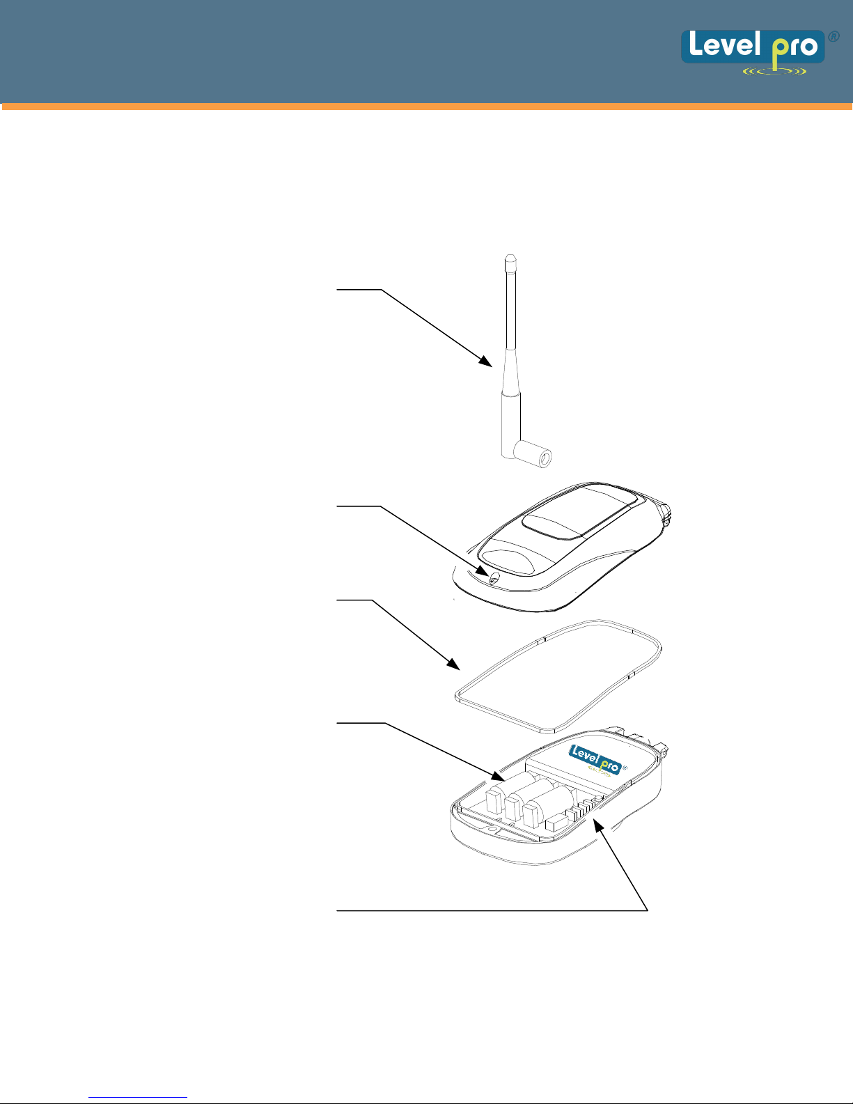
8 Replacement Parts
The following parts are field replaceable and can be purchased thru Icon Process
Controls Customer Service at 905.469.9283
Antenna
Captive Screw
Housing Gasket
Li-Ion Battery
Model CR-123A
Replacement Jumper
Page 16

Sentinel Series | Telemetry
Tank | Sump Liquid Level Monitoring
9 Terms and Conditions of Service
This section explains the relationship between the user
It explains our respective legal rights concerning all aspects of our relationship, including:
• Billing and extra charges
• Starting and ending service
• Privacy and confidentialit
• Early Termination fees ( if applicable )
• Limitations of liability and warranty
If you use the service or the equipment, or if you pay any amount billed to your account, you consent
to the terms and conditions set forth in this agreement. If you do not agree with these terms and
conditions, do not use the service and equipment and notify us immediately to cancel service.
1. Service
This is an agreement for Remote Data Delivery and associated Services between you and
Icon Process Controls. The term "Unit" is the device which is used to communicate the data to
the Icon Process Controls Data Center.
The term
which is also a part of this agreement. The term of this agreement begins on the date that we
activate Service for the Unit. There may be an activation fee associated with the rate plan that you
select. In addition, if you select a rate plan which requires a fixed term of more than one month
(such as a one-year plan), you agree to purchase service for the full term. After the term expires,
or if there is not a fixed term associated with the service, then this agreement will continue in
force until terminated by either party with a 30-day notice. If you select a rate plan with a fixed
term of more than one month, you may terminate service within the first 30 days without a
penalty. If you terminate service after the initial 30 days but prior to the end of the term, or we
terminate following your default, you will be in material breach of this agreement and agree to
pay a cancellation fee as set forth in the rate plan document.
2. Rates
Your Service rates are described in your rate plan document. Your service rate may be based on
fees for data communication from your Unit and on fees for remote access to your data via the
internet or other electronic means. Additional fees may be added to your monthly fee for services
above your base rate. These additional fees and how they are calculated are described in your rate
plan document.
3. Data Availability and Service Interruptions
Wireless Data Transmission Service to the Levelpro® data center is normally available to your
unit when it is within the coverage area of a GS
to provide GSM SMS Data Service. Service is subject to transmission limitation or interruption
caused by weather, terrain, obstructions such as trees or buildings, and other conditions. Service
may
due to system capacity limits ( such as during peak usage periods ), system repairs, or
modifications. In addition, access to your information via the internet or other electronic means of
transmission may be temporarily limited due to system capacity limitations or maintenance.
Service interruption
4. Use of Service/Unit
You agree not to use the unit or service for
service without prior written contractual agreements with Icon Process Controls
of this agreement depends on the rate plan which was defined in a separate document
be limited in areas where GSM SMS coverage is not available or may be temporarily limited
may also result from non-payment by you.
y
of this equipment and Icon Process Controls
M Cellular Service provider who is under contract
any unlawful purposes. You may not resell your
Page 17

Sentinel Series | Telemetry
Tank | Sump Liquid Level Monitoring
10 Product Warranty and Notices
Icon Process Controls warrants that the equipment is and will remain free from defects in
workmanship and materials for a period of one (1) year from the date of delivery.
Within the warranty period, Icon Process Controls shall, without charge for labor or
materials, repair or replace any defective components provided that reasonable care has
been exercised in protecting the equipment from adverse conditions and rough handling.
This warranty does not cover customer instruction, installation, set up adjustments, or signal
reception problems. This warranty does not cover cosmetic damage or damage due to acts of
God, accident, misuse, abuse, negligence, or modification of, or to any part of this
equipment, including the antenna. This warranty does not cover damage due to improper
operation or maintenance, connection to an improper voltage supply, or attempted repair by
anyone other than an authorized service facility. This warranty does not cover consumables
such as a fuse or battery.
This Limited Warranty is in lieu of all other warranties, express or implied (including
implied warranties of merchantability and fitness for a particular purpose), and of
all obligations or liabilities of Icon Process Controls for damages, including but not limited
to consequential and incidental damages, arising out of or in connection with the use or
performance of the equipment.
Icon Process Controls shall not be liable for any damages or loss arising from the use of
the data from this equipment or the Icon Process Controls web site.
 Loading...