

Page 1
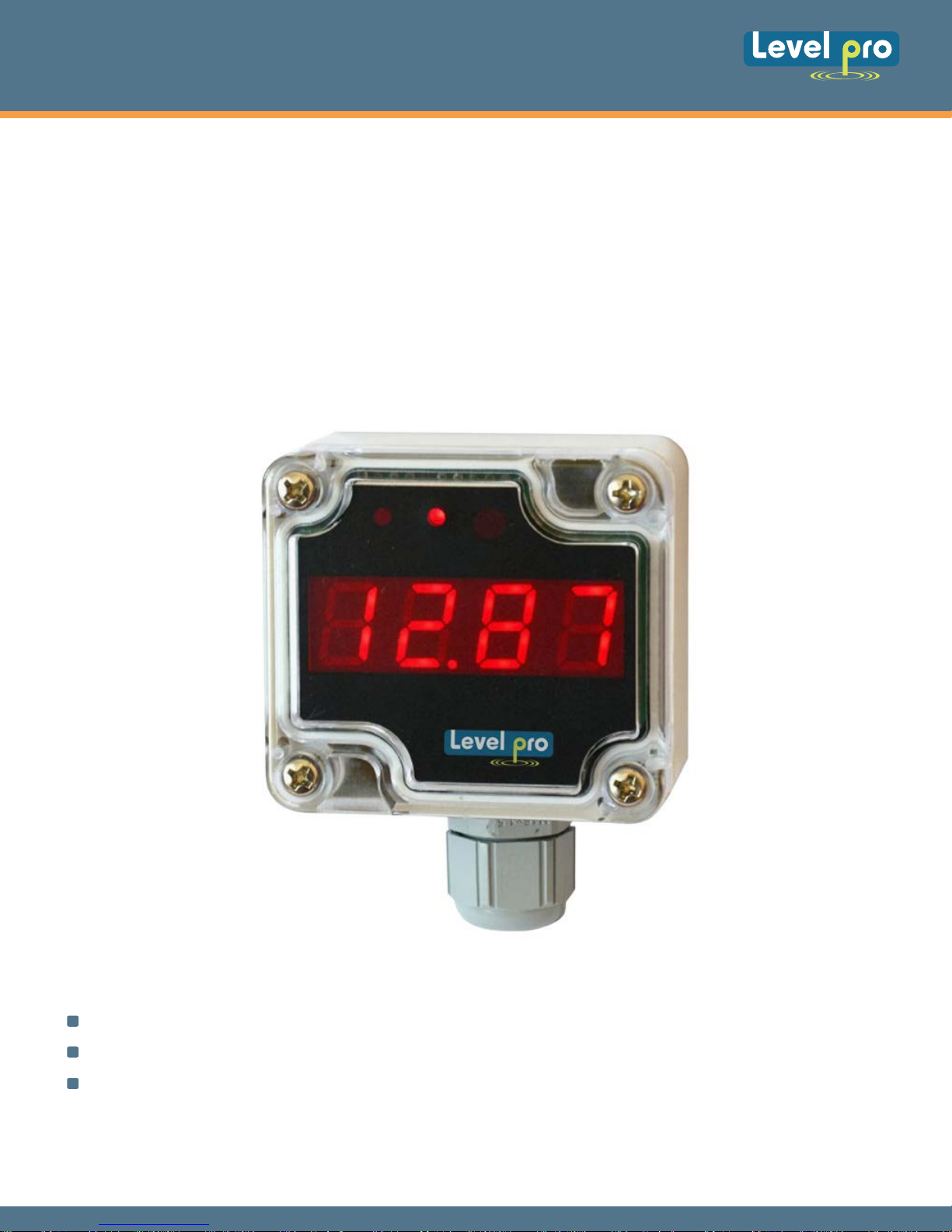
250 SERIES
Loop Powered Display
USER MANUAL
FLOW METER ITC 250 SERIES
Firmware: V.1.00 or Higher
Input Type: 4-20 mA
Supply from Current Loop 4-20 mA
Read the user's manual carefully before starting to use the unit or software.
Manufacturer reserves the right to implement changes without prior notice.
* Quick Start Programming Menu
Page 17
Page 2

250 SERIES
Loop Powered Display
* Quick Start Programming Menu
TABLE OF CONTENTS
1. BASIC REQUIREMENTS AND USER SAFETY
2. GENERAL CHARACTERISTICS
3. TECHNICAL DATA
4. DEVICE INSTALLATION
4.1. UNPACKING
4.2. ASSEMBLY
4.3. CONNECTION METHOD
4.4. MAINTENANCE
DESCRIPTION OF THE FRONT P
5.
6. PRINCIPLE OF OPERATION
MEASUREMENT MODE
6.1.
ANEL AND IR REMOTE CONTROLLER PUSH-BUTTONS
Page 17
02
03
03
04
04
04
05
07
07
08
08
6.2. DETECTION OF THE P
6.3. CONTR
7. DEVICE PROGR
7.1. PROGR
7.2. PAR
7.2.1. Numeric paramet
7.2.2. Swit
7.3. MENU DESCRIPTION
7.3.1. “
7.3.2. “
7.3.3. ”HOLd” menu
7.3.4. “
7.3.5. “
OL OF THE RELAY OUTPUT
AMMING MENU
AMETERS EDITION.
rEL” menu
inPt” menu
Scod” parameter
dEFS” parameter
EAK VALUES
AMMING
ers (digit change mode)
ch parameters (“LIST” type)
09
09
10
10
11
11
11
12
12
13
15
16
16
7.3.6. “
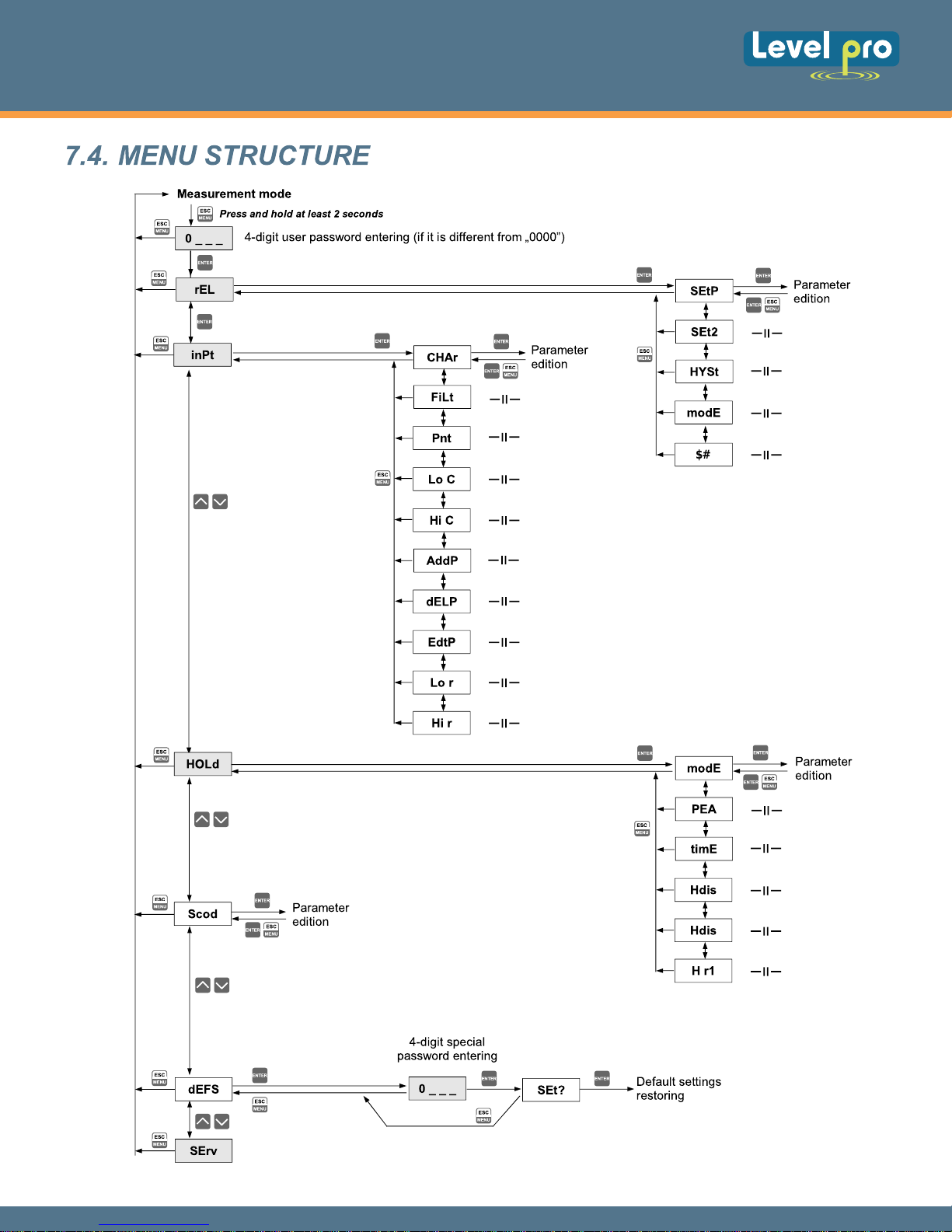
7.4. MENU STRUCTURE
SErv” menu
16
17
01
Page 3
250 SERIES
Loop Powered Display
Explanation of symbols used in the manual
This symbol denotes especially important guidelines concerning the installation
and operation of the device. Not complying with the guidelines denoted by this
symbol may cause an accident, damage or equipment destruction.
IF THE DEVICE IS NOT USED ACCORDING TO THE MANUAL THE USER IS
RESPONSIBLE FOR POSSIBLE DAMAGES.
This symbol denotes especially important characteristics of the unit. Read any
information regarding this symbol carefully.
1. BASIC REQUIREMENTS AND USER SAFETY
Do not use the unit in areas threatened with excessive shocks, vibrations, dust, humidity, corrosive
gasses and oils.
Do not use the unit in areas where there is risk of explosions.
Do not use the unit in areas with significant temperature variations, exposure to condensation or ice.
Do not use the unit in areas exposed to direct sunlight.
Make sure that the ambient temperature (e.g. inside the control box) does not exceed the
recommended values. In such cases forced cooling of the unit must be considered (e.g. by using a
ventilator).
The manufacturer is not responsible for any damages caused by inappropriate installation, not
maintaining the proper environmental conditions and using the unit contrary to its assignment.
Installation should be conducted by qualified personnel . During installation all available safety
requirements should be considered. The fitter is responsible for executing the installation according
to this manual, local safety and EMC
regulations.
GND input of device should be connected to PE wire;
The unit must be properly set-up, according to the application. Incorrect configuration can cause
defective operation, which can lead to unit damage or an accident.
If in the case of a unit malfunction there is a risk of a serious threat to the safety of people or
property additional, independent systems and solutions to prevent such a threat must be used.
The unit uses dangerous voltage that can cause a lethal accident. The unit must be switched off
and disconnected from the power supply prior to starting installation of troubleshooting (in the case
of malfunction).
Neighboring and connected equipment must meet the appropriate standards and regulations
concerning safety and be equipped with adequate overvoltage and interference filters.
Do not attempt to disassemble, repair or modify the unit yourself. The unit has no user serviceable
parts. Defective units must be disconnected and submitted for repairs at an authorized service
center.
The unit is designed for operation in an industrial environment and must not be used in a
household environment or similar.
02
Page 4
250 SERIES
Loop Powered Display
2. GENERAL CHARACTERISTICS
The ITC
250 is a simple digital wall-mounted indicator equipped with one measurement input (current
input, 4-20mA) used simultaneously as device power supply input. The current input has includes an
over-current protection circuit which protects standard resistor. The ITC 250 allows user to select a
conversion characteristic of several kinds: linear, square, square root, and user defined (max.20
points length). The Display consists of 4-digits. The displayed values can be selected by the user,
within the range of (-999 to 9999) including one decimal point.
Optionally ITC 250 can be equipped with bistable relay output. The device can be configured via IR
remote controller.
IR remote controller is not a part of the ITC 250 and must be ordered separately.
3. TECHNICAL DATA
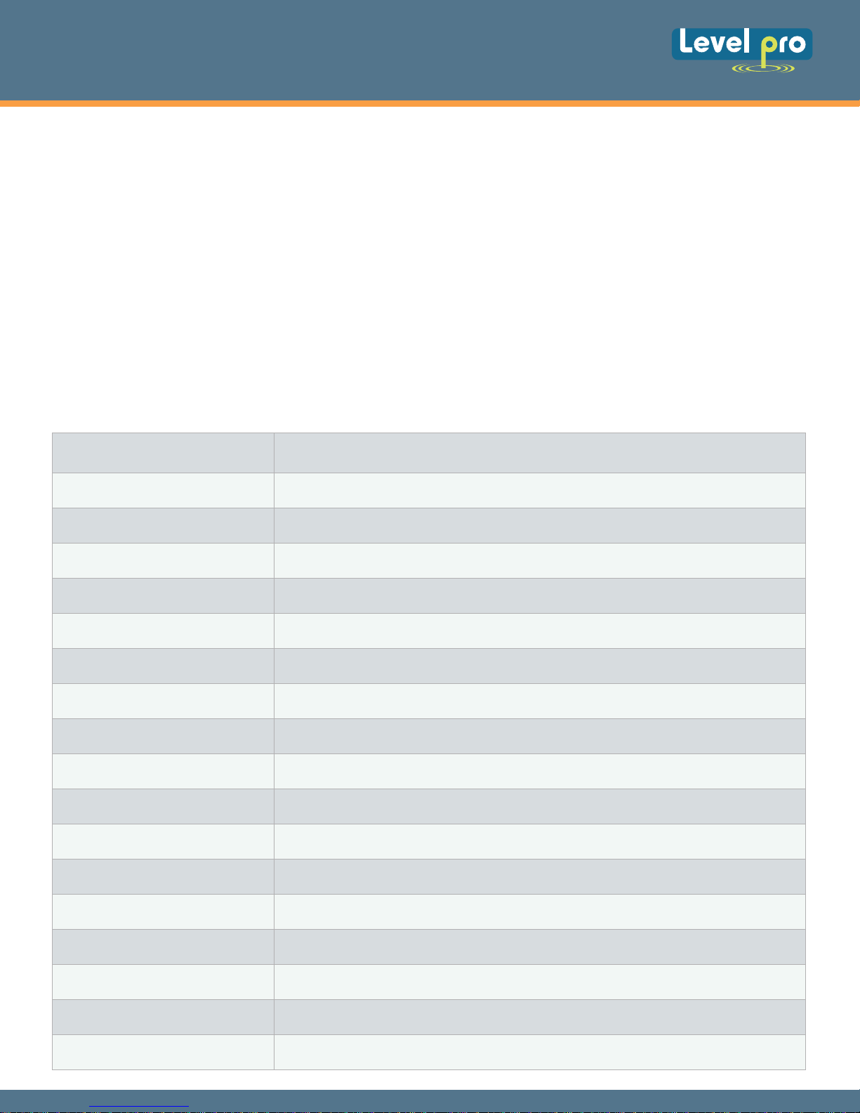
Minimal Supply
Current
Measurement Loop
voltage Drop
Current Input
Current Measurement
Accuracy
3.5 mA | device supplied from current loop
Max. 7 V
4÷20 mA overload protected | maximum input current about 50 mA
± 0,1% @ 25°C | ± One Digit
Temperature Stability
Display Range
Accepted Prolonged
Input Overload
Relay Output
Display
Data Memory
Protection Level
Housing Type
Housing Material
Housing dimensions
Operating Temperature
Model Dependant
Storage Temperature Model Dependant
50 ppm | °C
-999 ÷ 9999 | plus decimal point
20%
Bistable 0.5A|30V AC (cos j = 1), min. switching delay: about 4 sec.
LED, 4 digit | 13mm height, Red
Non-volatile memory | EPROM type
IP 65
Wall Mounted
ABS + fibreglass
Without Glands: 64 x 58 x 36 mm
With Glands: 64 x 82 x 36 mm
0°C to +50°C
or -20°C to +50°C
-10°C to +70°C | -20°C to +70°C
Mounting
Connection Cable
to wall | 2 M3 bolts
Without relay : 2 Core Cable (Power Supply)
With relay : 4 or 5 core cable (2 power supply wires + 2 or 3 wires for relay)
www. levelprosales.com
03
Page 5
250 SERIES
5D
Loop Powered Display
Max. Connection
Leads Diameter
EMC
This is a class A unit. In a residential or a similar area it can cause radio frequency
interference. In such cases the user can be requested to use appropriate preventive
measures.
DEVICE INSTALLATION
4.
The
interference that may occur within a typical industrial environment. In order to take full advantage of
these characteristics the installation of the unit must be conducted correctly and according to the
local regulations.
has been designed and manufactured ensuring a high level of user safety and resistance to
unit
Installation should be conducted by qualified personnel.
Read the basic safety requirements on page 3 prior to starting the installation.
All installation works must be conducted with a disconnected power supply.
2,5 mm2
According to: PN-EN 61326-1
4.1. UNPACKING
After removing the unit from the protective packaging, check for transportation damage. Any
transportation damage must be immediately reported to the carrier. Also, write down the unit serial
number on the housing and report the damage to the manufacturer.
Included with the unit
User's Manual,
Warranty,
4.2. ASSEMBLY
Disconnect the power supply prior to starting assembly.
Check the connections are wired correctly prior to switching the unit on.
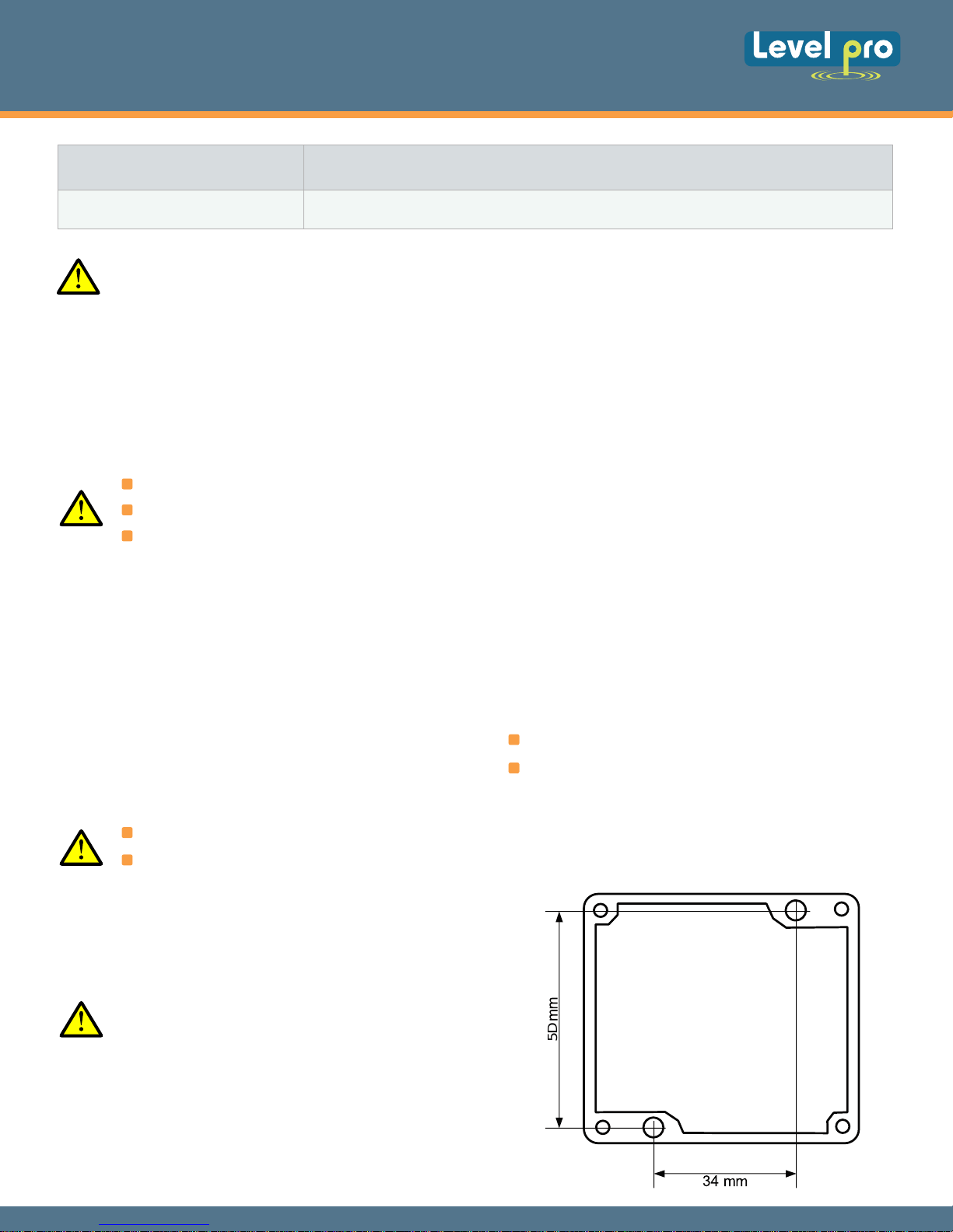
To install device on the wall, a pinholes
should be made. Figure 4.1 presents
dimensions of the device and distances
between holes. The back side of the device
has four mounting holes. This part of the
case should be mounted to a wall by
screws.
04
Page 6
250 SERIES
Loop Powered Display
4.3. CONNECTION METHOD
Installation should be conducted by qualified personnel. During installation all available
safety requirements should be considered. The installer is responsible for executing the
installation according to this manual, local safety and EMC regulations.
Wiring must meet appropriate standards and local regulations and laws.
Tighten the clamping screws. The recommended tightening torque is 0.5 Nm. Loose
screws can cause fire or defective operation. Over tightening can lead to damaging the
connections inside the units and breaking the thread.
The unit is equipped with housing, cover and gland or M12 connector, protecting against
water intrusion. Pay special attention to their correct tightening or clamping. In the case
of any doubt consider using additional preventive measures (covers, roofing, seals, etc.).
Carelessly executed assembly can increase the risk of electric shock.
Due to possible significant interference in industrial installations appropriate measures
assuring correct operation of the unit must be applied. To avoid the unit of improper
indications keep recommendations listed below.
CAUTION
Avoid common (parallel) leading of signal cables and transmission cables together with power
supply cables and cables controlling induction loads (e.g. contactors). Such cables should
cross at a right angle.
Contactor coils and induction loads should be equipped with anti-interference protection
systems, e.g. RC-type.
In the case of magnetically induced interference the use of twisted couples of signal cables (socalled “spirals”) is recommended.
Connections of measurement signal and relay output should be made by screw connectors
mounted inside the housing.
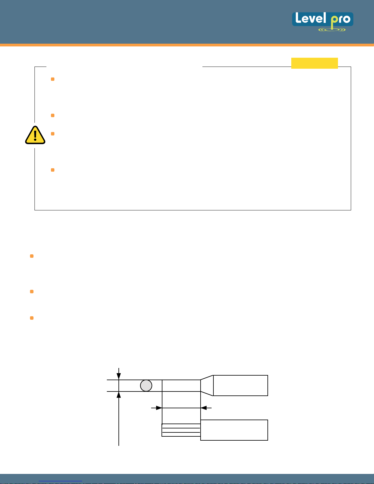
0.25"
max. 0.08"
Figure 4.2. Method of cable insulation replacing and cable terminals
05
Page 7
+
-
1
2
5
3
4
250 SERIES
Loop Powered Display
ON
3
4
R
+
1
5
OFF
2
-
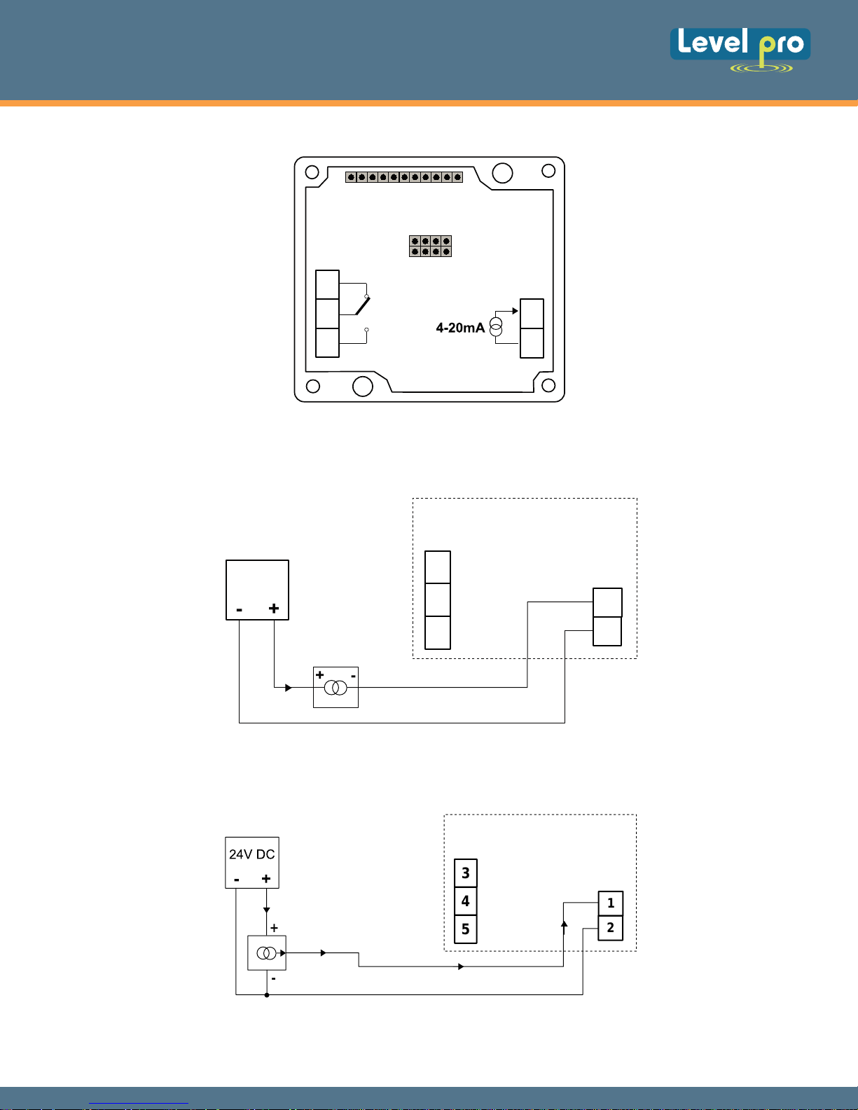
Figure 4.3. Terminals description
3
24V DC
4
5
Figure 4.4. Connection of 2-wire current converters
1
2
Figure 4.5. Connection of 3-wire current converters
www. levelprosales.com
www. levelprosales.com
06
Page 8
250 SERIES
Loop Powered Display
4.4. MAINTENANCE
The unit does not have any internal replaceable or adjustable components a vailable to the u ser. Pay
attention to the ambient temperature in the room where the unit is operating. Excessively high
temperatures can result in damage to the internal components and shorten the fault-free time of unit
operation.
In cases where the unit gets dirty do not clean with solvents. For cleaning u se warm water with small
amount of detergent or in the case of more significant contamination ethyl or isopropyl alcohol.
Using any other agents can cause permanent damage to the housing.
Product marked with this symbol should not be placed in municipal waste.
Please check local regulations for disposal of electronic products.
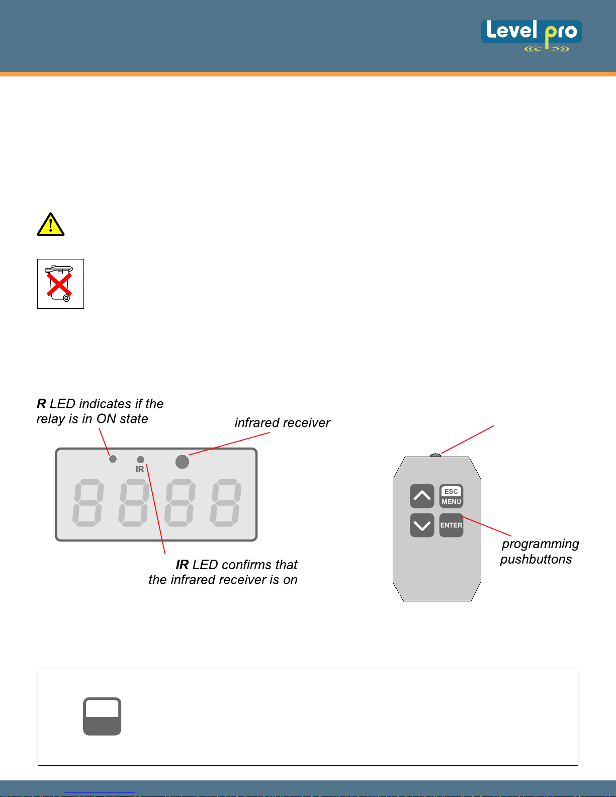
5. DESCRIPTION OF THE FRONT PANEL AND IR REMOTE
CONTROLLER PUSH-BUTTONS
infrared
transmitter
+
Symbols and functions of Push Buttons:
Symbol used in the manual : [ESC/MENU]
ESC
MENU
Functions:
• Enter to main menu ( press and hold for at least 2 sec.)
• Exit the current Scr
• Cancel the changes made in parameter being edited
een and Enter to previous menu (or measure mode)
07
Page 9
250 SERIES
Loop Powered Display
Symbol used in the manual : [ENTER]
Functions :
ENTER
• Start to edit the parameter
• Enter into the sub-menu
• Confirmation of changes made in parameter being edited
Symbol used in the manual : [^] [v]
Functions :
• Change of the present menu
• Modification of the parameter value
• Change of the display mode
6. PRINCIPLE OF OPERATION
Power to the 250 Series display is supplied from current loop. To ensure the display functions
correctly the signal of the current loop must be greater than 3.5mA. If signal value is below 3.5mA a
running decimal point is displayed. Device configuration using remote controller is possible if signal
value of current loop is greater than 10mA (Located on front panel LED marked “IR”).
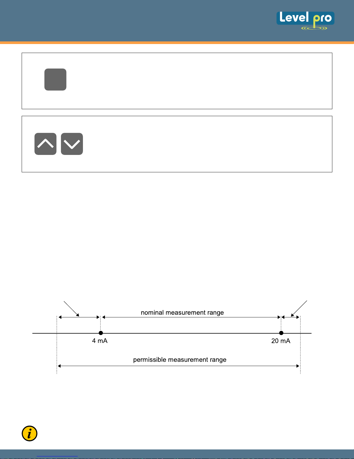
6.1 MEASURING PRICIPLE
The measurement range e
and the measurement range equal to the extended nominal range is called: permissible
measurement range (figure 6.1).
”Lo r” parameter
qual to the nominal range is called: nominal measurement range,
”Hi r” parameter
Figure 6.1. Definitions of measurement ranges in mode 4 ÷ 20mA
If the result of measurement exceeds the permissible measurement range, warning “-Hi-” or “-Lo-” is
displayed rather than input signal, depends on exceeded value (see description of “Lo r” i “Hi r”
parameters, paragraph “inPt” menu).
If the measurement value do not exceed the permissible measurement range
exceeds range -999 ÷ 9999, the warning “-Ov-” is displayed rather than the calculated result.
, but displayed value
08
Page 10
250 SERIES
Loop Powered Display
Configuration of the device via menu does not interrupt the level measurement.
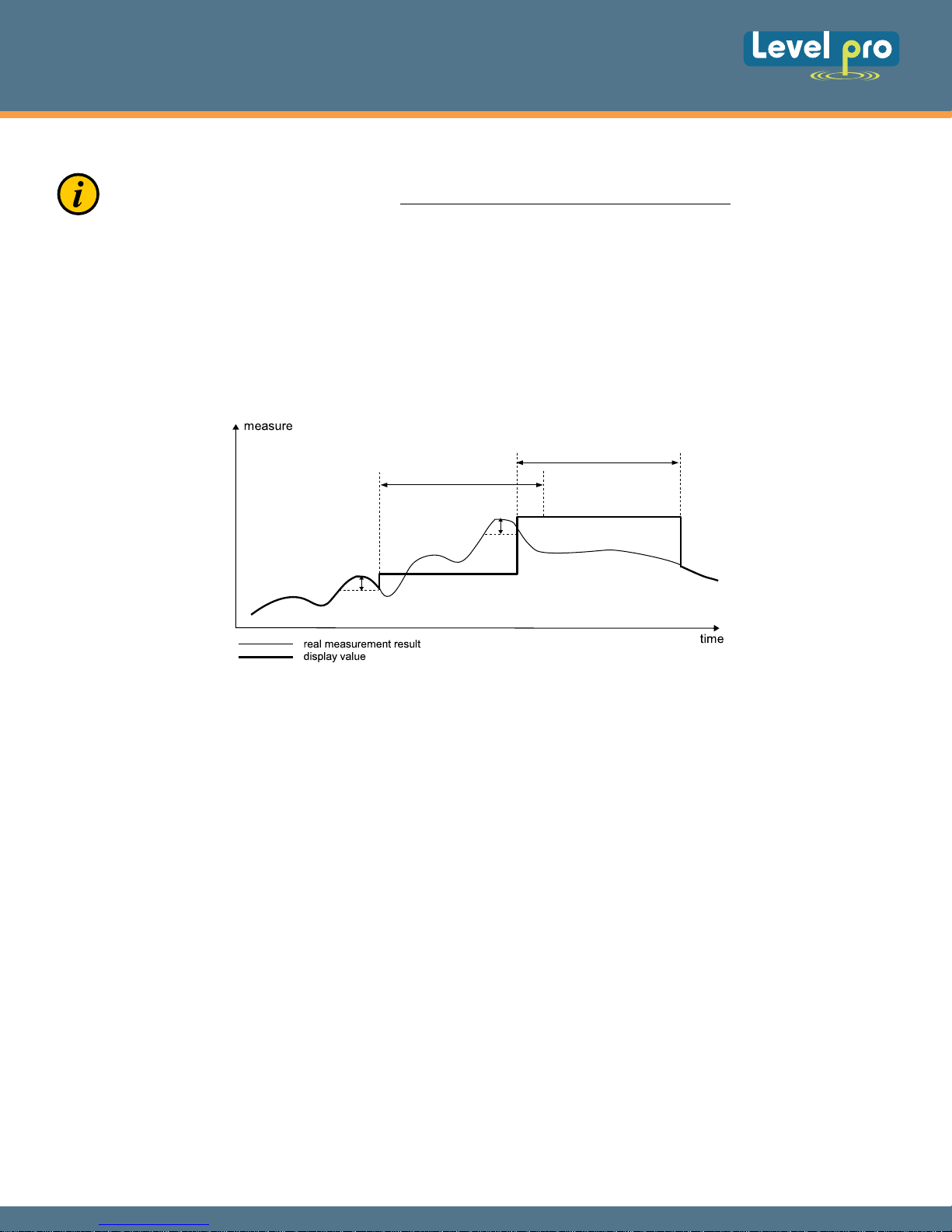
6.2. DETECTION OF THE PEAK VALUES
The ITC 250 controller is equipped with a peak detection function. It can detect the input signal peaks
and display their values. Presets connected with this function are placed in “HOLd” menu (see
description of “HOLd” menu).
”timE”
”timE”
”PEA”
”PEA”
Figure 6.4. Process of peaks detection
6.3. CONTROL OF THE RELAY OUTPUT
The 250 Series display is equipped with one bistable SPDT relay output. When energized it will LED
'R' will light up. It is not possible to change relay state until after 10 seconds has elapsed since the
device has been powered on. The display must be powered by at least 3.5 mA current. After the
display is properly powered the change of relay state is four (4) seconds. During device power off the
relay is set according to the value of “AL” parameter.
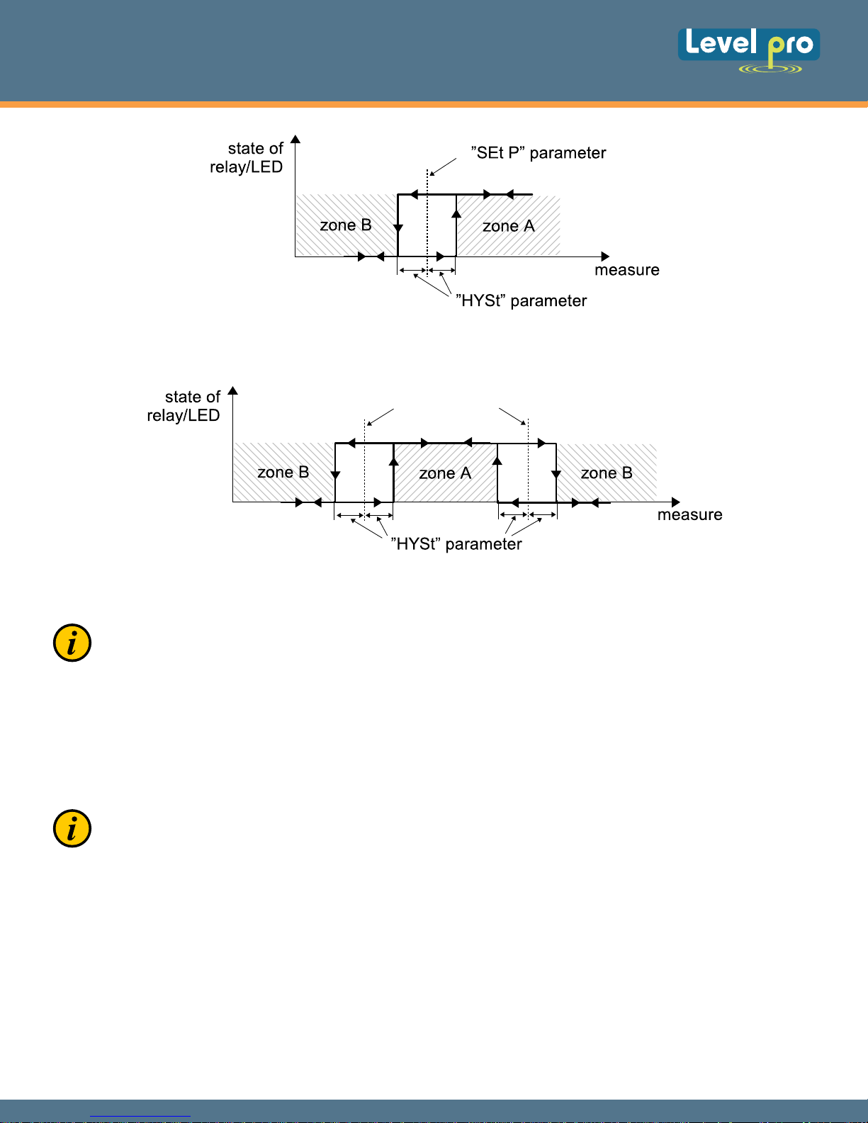
The different modes of the control can be changed and are dependent on the parameter values for
“SEtP”, “SEt2”, “HYSt”, “modE” and “AL”. The “modE” parameter will also the
controlled over one or two thresholds values. If one threshold is used (figure 6.4) the relay can be
turned on (“modE” = “on”) or off (“modE” = “oFF”) when the input signal value enters the zone A. If
two thresholds are used (figure 6.5) the relay will be turned on when value of input signal enters the
zone A (“modE” = “in”) or zone B (“modE” = “out”) and turned off if the signal enters the second
one.
relay to be used or
09
Page 11
250 SERIES
Loop Powered Display
Figure 6.5. One threshold control of the relay/LED outputs
”SEt P” or ”SEt P2” parameter
Figure 6.6. Two threshold control of the relay/LED outputs
The relay outputs and LEDs (named "R") can be controlled depend on both - the current value
and the peak value (when peak detection is active, for flow rate only) of the input signal.
7. DEVICE PROGRAMMING
The display menu allow user to set all parameters connected to operation of measurement input,
control modes, critical situations behavior (relay) and access settings. The meaning of the particular
parameters is described in paragraph MENU DESCRIPTION.
The device is configured via IR
and the temperature must be at least 0°C in order to do that.
remote controller but it must be supplied at least by 10mA current
7.1. PROGRAMMING MENU
To enter main menu (measurement mode) the operator must to press and hold the [ESC/MENU]
button for a minimum of two (2) seconds
If the user password is defined (see parameter “Scod”), the operator will have to correctly enter it at
this point prior to proceeding to menu options .
After entering of last digit of the correct password the first menu position will be displayed if the
password is incorrect that a warning “Err” will be displayed.
10
Page 12
250 SERIES
Loop Powered Display
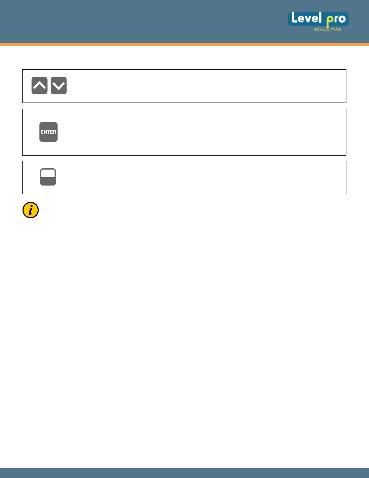
Functions of the buttons while sub-menu and parameters choice:
Selection of sub-menu or parameter for editing. Name of selected item (submenu or
parameter) is displayed.
Operation of [ENTER] button depend on present menu position:
• if the name of some sub-menu is displayed - Press Enter; the name of the first parameter
(or next level sub-menu) is then displayed,
• if the name of some parameter is displayed - Press Enter; present value of the parameter is
displayed
ESC
MENU
After about 1 minute of inactivity (since last use of the button), the device exits the menu mode
and returns to the measurement mode.
[ESC/MENU] button allow user to exit present menu level and move to upper level menu
(or measurement mode).
7.2. PARAMETERS EDITION
To start edition of any parameter user should select name of desired one using [^] [v] buttons and
then press [ENTER].
7.2.1. Numeric parameters (Digit Change Mode)
Numerical p arameters a re d isplayed a s decimal n umbers. T he m ode o f i ts new v alue e ntering
depends on chosen edit method ( see parameter “Edit”).
In mode “by digit” (“Edit”=“dig”) pressing one of t he keys [^] or [v] causes change of current position
(flashing digit) or the sign (+/-). S hort p ressing of the [ENTER] button c auses change of the p osition
(digit).
Press [ENTER] at least 2 seconds to accept the changes, after that question “SEt?” is displayed, and
user must to confirm (or cancel) the changes. To confirm changes (EEPROM) press the [ENTER]
button shortly after “SEt?” is displayed. To cancel the changes press [ESC] button shortly after
“SEt?” is displayed. The device will then return to the main menu.
7.2.2. Switch parameters (“LIST” type)
Switch parameters can be described as a s ets of values (a lists) out of which only one o f the options
available on the list can be selected f or t he g iven parameter. O ptions of switching parameter are
selected using [^], [v] keys.
Pressing of the [ENTER] will prompt the user to acknowledge the question (“SEt?”). If key [ENTER] is
pressed once again, the changes are accepted and will be stored in EEPROM. Pressing the key [ESC]
after “SEt?” will cancel any changes and will return to the main display menu.
11
Page 13
250 SERIES
Loop Powered Display
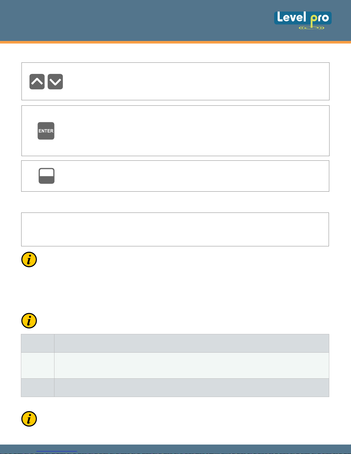
Functions of buttons when editing numeric and switching parameters :
While editing numeric parameter - change of current (flashing) digit.
While editing switch parameter - selection of switch parameter.
If numerical parameter is being changed or edited a quick pressing of the [ENTER]
button will change edited position. A longer press and hold (min 2 sec) of the [ENTER]
button will causes the display to prompt the user a “SEt?” ask, which allow user to
make sure if change of the parameter value is correct. If switch parameter is being
edited, a short press of [ENTER] button causes of display a “SEt?” ask. When
[ENTER] button is pressed again (while “SEt?” is displayed) the new value of the
parameter is stored in EEPROM memory.
ESC
MENU
Pressing this button operator can cancel the changes done up to now (if they were not
approved by [ENTER] button after the “SEt?” ask) and come back to menu
7.3. MENU DESCRIPTION
- password checking. If some password different from “0000” is set, then every enter to
“- - - -”
main menu follows the entering of password. If entered password is correct then first menu
position will be displayed else warning “Err”, and unit returns to measurement mode.
Due to problem with direct displaying of “m” letter, it is exchanged with special sign “m“.
Independently in user manual letter “m” is used to make it more readable (example: “modE”).
7.3.1. “rEL” menu
This menu allows to configure the operation mode of relay and LED marked “R”. Principle of the relay
operation is described in paragraph CONTROL OF THE RELAY OUTPUT.
The relay output and LED (named R) can be controlled depend on both - the current value and the
peak value (when peak detection is active) of the input signal.
“SEtP”
“SEt2”
“HYSt”
first threshold of the relay (range -999 ÷ 9999). Negative values can be input by selecting a “-” sign on first digit
(to change value use [^] and [v] buttons). Threshold is the medium value of relay hysteresis.
second threshold of the relay (range -999 ÷ 9999). Negative values can be input by selecting a “-” sign on first
digit ( to change value use [^] and [v] buttons). This threshold is accessible when “modE” parameter is set to
“in” or “out” value. Threshold is the medium value of relay hysteresis.
hysteresis of relay (range 0 ÷ 999). Full hysteresis of the relay is equal to 2x “HYSt” parameter.
The relay state can change when an input signal is out of threshold-hysteresis to threshold+hysteresis zone.
Presented parameters should be set to ensure that “SEtP” + ”HYSt”, “SEt2” + ”HYSt”, “SEtP” ”HYSt” or “SEt2” - ”HYSt” do not exceeds the measure range. Additionally, in two threshold mode
(“modE” = “in” or “out”), the hysteresis for both thresholds must not cover each other (in other
case relay can't change its state).
12
Page 14
250 SERIES
Loop Powered Display
"modE" - relay operation mode:
“noAc”
“on”
“oFF”
“in”
“out”
“AL”
the relay is not active (doesn’t change state)
one threshold mode, the relay turns ON when input signal exceeds from the bottom SEtP+HYSt value, and turns
OFF when exceeds from the top SEtP-HYSt,
one threshold mode, the relay turns ON when input signal exceeds from the top SEtP-HYSt value, and turns OFF
when exceeds from the bottom SEtP+HYSt,
- two threshold mode, the relay turns ON when the input signal exceeds from the bottom
“lower threshold + HYSt” or from the top “bigger threshold - HYSt”, and turns OFF when exceeds from the
top “lower threshold - HYSt” or from the bottom “bigger threshold + HY
one of “SEtP” and “SEt2” thresholds, the lower threshold means lower one of “SEtP” and “SEt2” thresholds.
- two threshold mode, the relay turns ON when the input signal exceeds from the top “lower threshold - HYSt”
or from the bottom “bigger threshold + HYSt”, and turns OFF when exceeds from the bottom
“lower threshold + HYSt” or from the top “bigger threshold
“SEtP” and “SEt2” thresholds, the lower threshold means lower one of “SEtP” and
- HYSt”. The bigger threshold means bigger one of
St”. The bigger threshold means bigger
“SEt2” thresholds.
• LED lights when “ON” part of the relay is closed, independently of relay’s mode.
• When power supply fail, unit sets relay state accordingly to “AL” parameter.
- this parameter defines the relay reaction when some critical situations occurs:
“noCH” - relay do not change his state,
“on” - relay will be turned ON,
“oFF” - relay will be turned OFF.
If parameter “modE” is set to “on” , “oFF”, “in” or “Out” the “critical situation” means that
allowable measurement range is exceeded.
• If option “noCH” is selected for “AL” parameter, behaviour of the relay may depend on “FiLt”
parameter in some cases. If “FiLt” is set to big value and the input signal drops, result value of the
measure will change slow, causes of turning on or off relay due to thresholds values. The critical
situation is slowly detected, so it is impossible to predict the relay state in that situations.
• If parameter “AL” = “on”, the relay will be turned on in the critical situations, even if his parameter
“modE” = “noAC”.
7.3.2. “inPt” menu
This menu presets the measurement input:
- this option presets type of the conversion characteristic, and can be set to:
“CHAr”
“Lin” - linear
“Sqr” - square
“Sqrt” - square root
“USEr”-
user defined characteristic. Maximal length 20 points. Every point is defined by user. Adding,
Editing and Deleting of points is done by options “AddP”, “EdtP”, “dELP” (“InPt” menu) respectively.
If user defined characteristic is selected, and if number of defined points is lower than 2 then warning
“Errc” is displayed in measurement mode.
When one of those characteristics is chosen display
range is defined by “Lo C” and “Hi C”.
}
13
Page 15
250 SERIES
Loop Powered Display
The process of displayed result calculation is described in details in DISPLAY VALUES CALCULATION
paragraph.
“FiLt”
“Pnt”
“Lo C”
“Hi C”
- this parameter sets filtration rate. It can be set to values from 0 (no filtration )
to 5 (strongest filtration – time window about 3 sec).
- decimal point position. It can be set to one of :
“0”, “0.0”, “0.00”, “0.000”
Decimal point position is changed by [^], [v] buttons.
These parameters describe the values displayed for minimum and maximum input current. “Lo C” parameter
defines the value displayed when input current is equal 4 mA, and “Hi C” parameter defines the value displayed
for 20 mA of input current. Available range for these parameters: -999 ÷ 9999. Negative values can be set by
entering '-'
sign on the first position (by use of [^], [v] buttons).
If user defined characteristic is selected (parameter “CHAr” = “USEr”) the parameters “Lo C” and “Hi C”
are not available for modification, due to their values are calculated from defined characteristic.
- this menu allow user to add single point to the user defined characteristic. After selection of this option device
waits for “X” and “Y” coordinates of new point. Modification of the coordinates is done accordingly to numerical
“AddP”
parameters edition. Coordinate “X” defines the percentage ratio of input current to selected current range.
The “X” range: -99,9 ÷ 199,9. Coordinate “Y”
changed in range: -999 ÷ 9999, decimal point position depend on “Pnt” parameter (menu “inPt”).
defines displayed value for particular
“X” value. The “Y” value can be
• User can not enter two points with the same value of “X” coordinate. If user trays to do it, “Err”
warning is displayed. To modify any defined point use “EdtP” option.
• To distinguish “X” and “Y” c
oordinates, if “X” coordinate is displayed an additional decimal point on
utmost right position is displayed.
• If user defined characteristic is selected, and if number of defined points is lower than 2 then warning
“Errc” is displayed in measurement mode.
“dELP”
“Pnt”
“AddP”, “dELP” and “EdtP” options are available only if the user defined characteristic is used (it
means when parameter “CHAr” = “USEr”).
“Lo r”, “Hi r”
- this option allows user to delete any of the points of the user defined characteristic. After selection current
number of points of the user defined characteristic is displayed for about approx. 1.5 sec. After that device
waits for selection of point being deleted (by [^], [v] buttons). The short pressing of
switching between X and Y value of the displayed point. The long press (press and hold at least 2 sec) of [ENTER]
button causes by displaying “dEL?” ask. If [ENTER] button is pressed again, current point i
updated number of points of the user defined characteristic is displayed.
- this option allows user to modify of particular point of the user defined characteristic. After selection current
number of points of the user defined characteristic is displayed for about approx. 1.5 sec. After that device waits
for selection of point being edited (by [^], [v] buttons). The short pressing of [ENTER] button causes by switching
between X and Y value of the displayed point. The long press (press and hold at least 2 sec) of [ENTER] button
causes by entering to edit the selected coordinate of the point. Modification of the coordinates is done
accordingly to nume
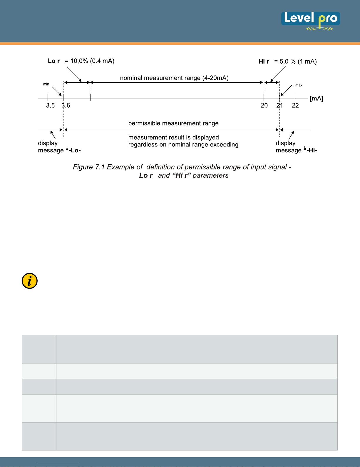
- these parameters define the expansion of nominal range in percent. They determine the permissible range
of input signal (figure 7.1).
The permissible range allow user to exceed the nominal range of input signal. If input value is contained in the
permissible range a proper result is displayed. If input signal exceeds this range (defined by “Lo r” and “Hi r”),
“-Lo-” or “-Hi-” warning is displayed depend on input signal value.
rical parameters edition.
[ENTER] button causes by
s deleted and new
14
Page 16
250 SERIES
Loop Powered Display
" "
5
" "
"
"
" "
The “Lo r” parameter determines lower border of the permissible range calculated due to
expression: I
min = 4 mA - 4 mA × “Lo r” %.
The “Lo r” value can be set from 0 to 12.4%.
Parameter “Hi r” determines the upper border of the permissible range accordingly to the
expression: I
max = 20 mA + 20 mA × “Hi r” %.
The value of “Hi r” can be set from 0 to 19.9%
In example no 1 of the DISPLAY VALUES CALCULATION paragraph the procedure of the permissible
input range determining is presented in details.
If the measurement value do not exceeds permissible measurement range but displayed value exceeds
range -999 ÷ 9999, the warning “-Ov-” is displayed rather than the calculated result.
7.3.3. ”HOLd” menu
This menu contains parameters connected with peak detection function. See also full description of
the peak detection function in paragraph: DETECTION OF THE PEAK VALUES
- the type of detected changes of the input signal, can be set to values:
“modE”
“PEA”
“timE”
“HdiS”
“norm”- peaks - peak and next drop of the input signal of value equal at least “PEA”,
“inv” - drops - drop and next peak of the input signal of value equal at least “PEA”,
- minimal detected signal change classified as peak or drop (see Figure 6.2)
- maximum time of displaying of the peak (drop) value, can be set from 0.0 to 19.9 sec, with 0.1 sec. resolution.
- type of displayed values:
“rEAL”- current value is displayed,
“HOLd” - peak (drop) value is displayed,
- relay/LED output R operation mode:
“H r1”
“rEAL” - relay/LED operates depend on the current value,
“HOLd”- relay/LED operates depend on the peak (drop) value.
15
Page 17
250 SERIES
Loop Powered Display
7.3.4. “Scod” parameter
This parameter defines user password (4-digits number). If this parameter is set at value “0000”, user
password is turned off.
If the user do not remember his password, the access to the menu is possible by the “one-use
password”. To get this password please contact with Marketing Division. “Single use password”
can be used only one time, after that it is destroyed. Entering this password causes in clearing of
user password, it means sets the user password to “0000”.
The “one-use password” can be used ONE TIME ONLY, it is impossible to use it again! The “one-use
password” can be restored by Service Division only.
7.3.5. “ dEFS” parameter
This setting allows to restore the factory settings of the device. To get the access to this option
special password is required: “5465”, next the device displays acknowledge question “SEt?”. Press
[ENTER] to acknowledge the restoring of factory settings or [ESC] to cancel.
7.3.6. “SErv” menu
This menu contains the parameters for authorized service only. To enter this menu proper service
password must be entered. Improper settings can causes of damage of the device.
16
Page 18
$#
250 SERIES
Loop Powered Display
17
 Loading...