

Page 1

LevelOne
Secure WLAN Controller
WHG-311/315/401/505/515/707
User Manual
Page 2

Copyright
The contents of this publication may not be reproduced in any part or as a whole, stored, transcribed in an
information retrieval system, translated into any language, or transmitted in any form or by any means, mechanical,
magnetic, electronic, optical, photocopying, manual, or otherwise, without the prior written permission of LevelOne,
INC.
Disclaimer
LevelOne does not assume any liability arising out the application or use of any products, or software described
herein. Neither does it convey any license under its parent rights not the parent rights of others. LevelOne further
reserves the right to make changes in any products described herein without notice. The publication is subject to
change without notice.
Trademarks
LevelOne is a registered trademark of Digital Data Communications Group. Other trademarks mentioned in this
publication are used for identification purposes only and may be properties of their respective owners.
About 4ipnet
The LevelOne Secure WLAN Controller series is powered by 4ipnet. LevelOne is partnered with 4ipnet to deliver
most feature-rich product yet simple deployment in wireless networking infrastructure solution.
4ipnet is a leading provider of wireless networking solution soft ware desi gn hous e for manageable, reliable, and
secure wireless access. In an effort to meet changing market demands at the least possible cost, 4ipnet delivers a
diverse array of turnkey, high-performance products and mission-critical applications to bring reliability and
manageability to increasing l y complex wireless networks.
4ipnet’s complete WLAN infrastructure solution portfolio addresses the needs of different network operation
environments ranging from the ISP to the SOHO, with an emphasis on simplified network deployment, centralized
network management, and enhanced network perf ormance.
Page 3

FCC CAUTIO N
WHG-311
This equipment has been tested and pro ven to comply with the limits for a class B digital device, pursuant
to part 15 of the FCC Rules. These limits are designed to provide reasonable protection against harmful
interference in a residential installation. This equipment generates uses and can radiate radio frequency
energy and, if not installed and used i n accor dance with the i nstructi ons, may cause harmful inte rference to
radio communications. However, there is no guarantee that interference will not occur in a particular
installation. If this equipme nt does ca use harmful inter fe rence to radio or televis ion r ecepti on, which c an be
determined by turning the equipment off and on, the user is encoura ged to try to correct the inte rfer ence by
one or more of the following measures:
---Reorient or relocate the receiving a n tenna.
---Increase the separation between the equipment and receiver.
---Connect the equipment into an outlet on a circuit different from that to which the receiver is connected.
---Consult the dealer or an experie n ced radio/TV technician for help.
WHG-315, WHG-401, WHG-505, WHG-515, WHG-707
These equipments has been tested a nd found to comply with the li mits for a Class A digital device, pursuant
to Part 15 of the FCC Rules. These limits are designed to provide reasonable protection against harmful
interference when the equipment is opera ted i n a commercial envir onment. This equipme nt gene r ates, us es
and can radiate radio frequency energy and, if not installed and used in accordance with the instruction
manual, may cause harmful interference to radio communications. Operation of this equipment in a
residential area is likely to cause harmful interference in which case the user will be required to correct the
interference at his own expense.
Page 4

Table of Contents
1. Before You Start ................................................................................................... 8
1.1. Preface .............................................................................................................................. 8
1.2. Document Conventions ..................................................................................................... 8
2. WHG Controllers Installation Guide ................................................................... 9
2.1. WHG Controller Capacity Table ......................................................................................... 9
2.2. WHG Controller Hardware Overview ............................................................................... 10
2.2.1. WHG-311 Hardware ................................................................................................................. 10
2.2.2. WHG-315 Hardware................................................................................................................. 11
2.2.3. WHG-401 Hardware................................................................................................................. 12
2.2.4. WHG-505 Hardware................................................................................................................. 13
2.2.5. WHG-515 Hardware................................................................................................................. 14
2.2.6. WHG-707 Hardware................................................................................................................. 15
2.3. Preparation before the Installation ................................................................................... 16
2.4. Unpacking & Installing ..................................................................................................... 17
2.4.1. WHG-311 Package & Installation ............................................................................................. 17
2.4.2. WHG-315 Package & Installation ............................................................................................ 17
2.4.3. WHG-401 Package & Installation ............................................................................................ 18
2.4.4. WHG-505 Package & Installation ............................................................................................ 19
2.4.5. WHG-515 Package & Installation ............................................................................................ 19
2.4.6. WHG-707 Package & Installation ............................................................................................ 20
3. System Overview ............................................................................................... 22
3.1. System Concept .............................................................................................................. 22
3.2. Service Zone Concept ..................................................................................................... 26
3.3. AP Management Concept................................................................................................ 28
4. Getting Started ................................................................................................... 29
4.1. Accessing Web Management Interface ........................................................................... 29
4.2. Home Page ..................................................................................................................... 31
4.2.1. Setup Wizard ............................................................................................................................ 32
4.2.2. Quick Links ............................................................................................................................... 33
4.2.3. System Overview ..................................................................................................................... 34
4.2.4. Main Menu ............................................................................................................................... 35
4.2.5. Online Help .............................................................................................................................. 36
5. Initial Network Setup .......................................................................................... 37
5.1. Network Requirement ...................................................................................................... 37
5.2. Managing System Date & Time ....................................................................................... 37
5.3. WAN1 & WAN2 Setup ..................................................................................................... 38
5.4. WAN T raffic Control ......................................................................................................... 40
5.5. LAN Port & Service Zone Mapping .................................................................................. 41
5.6. LAN Partition -- Service Zone .......................................................................................... 44
5.6.1. Planning Your Internal Network ................................................................................................ 46
5.6.2. Configure Service Zone Network ............................................................................................. 47
5.6.3. WISPr Attributes in Service Zone ............................................................................................. 51
5.7. IPv6 ................................................................................................................................. 52
6. User Authentication and Grouping ................................................................... 54
6.1. Overview of User Authentication Database ...................................................................... 54
6.1.1. Configuring On-demand ........................................................................................................... 56
6.1.2. Configuring RADIUS ................................................................................................................ 73
6.1.3. Configuring Local ..................................................................................................................... 78
6.1.4. Configuring LDAP .................................................................................................................... 79
6.1.5. Configuring POP3 .................................................................................................................... 81
6.1.6. Configuring NT Domain ............................................................................................................ 82
6.1.7. Configuring SIP ........................................................................................................................ 83
6.1.8. Choosing Your Networks’ Authentication method .................................................................... 85
6.2. Users Group .................................................................................................................... 87
6.2.1. Assign users to a Group .......................................................................................................... 88
6.2.2. Permission in Service Zone ..................................................................................................... 90
6.2.3. QoS Traffic Class and Bandwidth Control................................................................................ 93
Page 5

6.3. User Login ....................................................................................................................... 94
6.3.1. An Example of User Login ....................................................................................................... 94
6.3.2. Default Authentication .............................................................................................................. 96
6.3.3. Login with Postfix ..................................................................................................................... 96
7. Policies and A cce ss C on t ro l ............................................................................. 97
7.1. Policy .............................................................................................................................. 97
7.1.1. Firewall ..................................................................................................................................... 99
7.1.2. Routing ................................................................................................................................... 104
7.1.3. Schedule ................................................................................................................................ 105
7.1.4. Session Limit .......................................................................................................................... 106
7.2. User Access Control ...................................................................................................... 107
7.3. Session Limit & Session Log ......................................................................................... 111
8. Users’ Login and Logout ................................................................................. 113
8.1. Befor e User Login ......................................................................................................... 113
8.1.1. Login with SSL ....................................................................................................................... 113
8.1.2. Internal Domain Name with Certificate .................................................................................. 114
8.1.3. Walled Garden ....................................................................................................................... 116
8.1.4. Walled Garden AD List ........................................................................................................... 117
8.1.5. Mail Message ......................................................................................................................... 119
8.2. After User Login ............................................................................................................ 120
8.2.1. Portal Home Page .................................................................................................................. 120
8.2.2. Idle Timer ............................................................................................................................... 121
8.2.3. Multiple Login ......................................................................................................................... 122
8.2.4. Change Password Privilege ................................................................................................... 123
8.2.5. Proxy Server .......................................................................................................................... 124
9. Local Area AP Management ............................................................................ 126
9.1. Multiple Type of AP ........................................................................................................ 127
9.2. Configure AP T emplate .................................................................................................. 128
9.3. AP Discovery ................................................................................................................. 131
9.3.1. AP Background Discovery ..................................................................................................... 133
9.4. Manually add AP ........................................................................................................... 134
9.5. AP with Service Zone .................................................................................................... 135
9.6. AP Security ................................................................................................................... 137
9.7. Change managed AP settings ....................................................................................... 138
9.8. AP Operations from AP List ........................................................................................... 141
9.8.1. Reboot, Enable, Disable and Delete the AP .......................................................................... 141
9.8.2. Apply T emplate ....................................................................................................................... 142
9.8.3. Apply Service Zone (Tag-Based Only) ................................................................................... 143
9.9. Firmware management and upgrade ............................................................................. 144
9.10. WDS Management ........................................................................................................ 145
9.11. Rogue AP Detection ...................................................................................................... 146
9.12. AP Load Balancing ........................................................................................................ 148
10. Wide Area AP Management ............................................................................. 151
10.1. AP Discovery ................................................................................................................. 152
10.2. Manually add AP ........................................................................................................... 153
10.3. Manage AP Lists ........................................................................................................... 154
10.4. Manage Third Party AP ................................................................................................. 156
10.5. Map ............................................................................................................................... 157
10.5.1. Register key from Google ...................................................................................................... 158
10.5.2. Create a Map ......................................................................................................................... 159
10.5.3. Marking APs on your Map ...................................................................................................... 160
10.5.4. Operations from Map page .................................................................................................... 163
10.6. AP Operations from AP List ........................................................................................... 164
10.7. WDS List ....................................................................................................................... 166
10.8. Backup Config ............................................................................................................... 167
10.9. Firmware management and upgrade ............................................................................. 168
10.10. CAPWAP ....................................................................................................................... 169
11. Networking Features of a Gateway ................................................................. 170
11.1. DMZ .............................................................................................................................. 170
11.2. Virtual Server................................................................................................................. 171
Page 6

11.3. Client Mobility ................................................................................................................ 172
11.4. DNS Cache ................................................................................................................... 173
11.5. Dynamic Domain Name Service .................................................................................... 174
11.6. Port and IP Forwarding .................................................................................................. 175
11.7. Dynamic Route .............................................................................................................. 176
12. System Management and Utilities .................................................................. 179
12.1. System Time ................................................................................................................. 179
12.1.1. NTP ........................................................................................................................................ 179
12.1.2. Manual Settings ..................................................................................................................... 180
12.2. Management IP ............................................................................................................. 181
12.3. Access History IP .......................................................................................................... 182
12.4. SNMP ............................................................................................................................ 183
12.5. Change Password ......................................................................................................... 184
12.6. Backup / Restore and Reset to Factory Default ............................................................. 185
12.7. Firmware Upgrade ......................................................................................................... 186
12.8. Restart .......................................................................................................................... 187
12.9. Network Utility ............................................................................................................... 188
12.10. Certificate ...................................................................................................................... 190
12.11. Administrator Account.................................................................................................... 193
12.12. Monitor IP ...................................................................................................................... 196
12.13. Console Interface .......................................................................................................... 197
13. System Status and Reports ............................................................................ 200
13.1. View the Status ............................................................................................................. 200
13.1.1. System Status ........................................................................................................................ 201
13.1.2. Interface Status ...................................................................................................................... 203
13.1.3. HW ......................................................................................................................................... 205
13.1.4. Routing Table ......................................................................................................................... 206
13.1.5. Online Users .......................................................................................................................... 207
13.1.6. Non-Login Users .................................................................................................................... 208
13.1.7. Session List ............................................................................................................................ 209
13.1.8. User Logs ............................................................................................................................... 210
13.1.9. Local User Monthly Network Usage ....................................................................................... 212
13.1.10. Logs ....................................................................................................................................... 213
13.1.11. DHCP Lease .......................................................................................................................... 214
13.2. Notification .................................................................................................................... 215
13.2.1. SMTP Settings ....................................................................................................................... 216
13.2.2. SYSLOG Settings .................................................................................................................. 217
13.2.3. FTP Settings .......................................................................................................................... 218
13.2.4. Notification Settings ............................................................................................................... 219
13.2.5. System Report ....................................................................................................................... 222
14. Virtual Private Network (VPN) ......................................................................... 223
14.1. Local VPN ..................................................................................................................... 223
14.2. Remote VPN ................................................................................................................. 227
14.3. Site-to-Site VPN ............................................................................................................ 228
15. Customization of Portal Pages ....................................................................... 230
15.1. Customizable Pages ..................................................................................................... 230
15.2. Loading a Customized Login Page ................................................................................ 231
15.3. Using an External Login Page ....................................................................................... 234
15.4. Load a Customized Logout Page .................................................................................. 235
15.5. How External Page Operates ........................................................................................ 236
15.6. Disclaimer Pag e ............................................................................................................ 251
16. Payment Gateways .......................................................................................... 253
16.1. Payments via Authorize.Net........................................................................................... 253
16.2. Payments via PayPal..................................................................................................... 257
16.3. Payments via SecurePay .............................................................................................. 259
16.4. Payments via WorldPay ................................................................................................ 261
17. Additional Applications ................................................................................... 264
17.1. Upload / Download Local Users Accounts ..................................................................... 264
17.2. Backup / Restore and Upload New On-demand Users Accounts ................................... 265
Page 7

17.3. Account Roaming Out ................................................................................................... 266
17.4. Seamless Cross Gateway Roaming .............................................................................. 267
Appendix A. Certificate Settings for IE6 and IE7 ................................................................. 269
Appendix B. Networ k Configuration on PC & User Login .................................................. 278
Appendix C. Policy Priority ................................................................................................... 291
Appendix D. RADIUS Accounting ......................................................................................... 292
Appendix E. VLAN Port Location Mapping and PMS Middleware ..................................... 299
Page 8
8
1. Before You Start
1.1. Preface
This WHG Controller User Manual is for WLAN service providers or network administrators to set up a network
environment using the WHG Controllers. It contains step-by-step procedures and graphic examples to guide MIS
staff or individuals with basic network system knowledge to complete the installation.
Besides this document, there is a “Quick Installation Guide” (QIG), which is for starting up WHG Controller quickly. It
is recommended to start with the QIG, and then refer to this manual for further details. Some special topics are
addressed separately in the Appendixes.
1.2. Docum ent Co n v enti ons
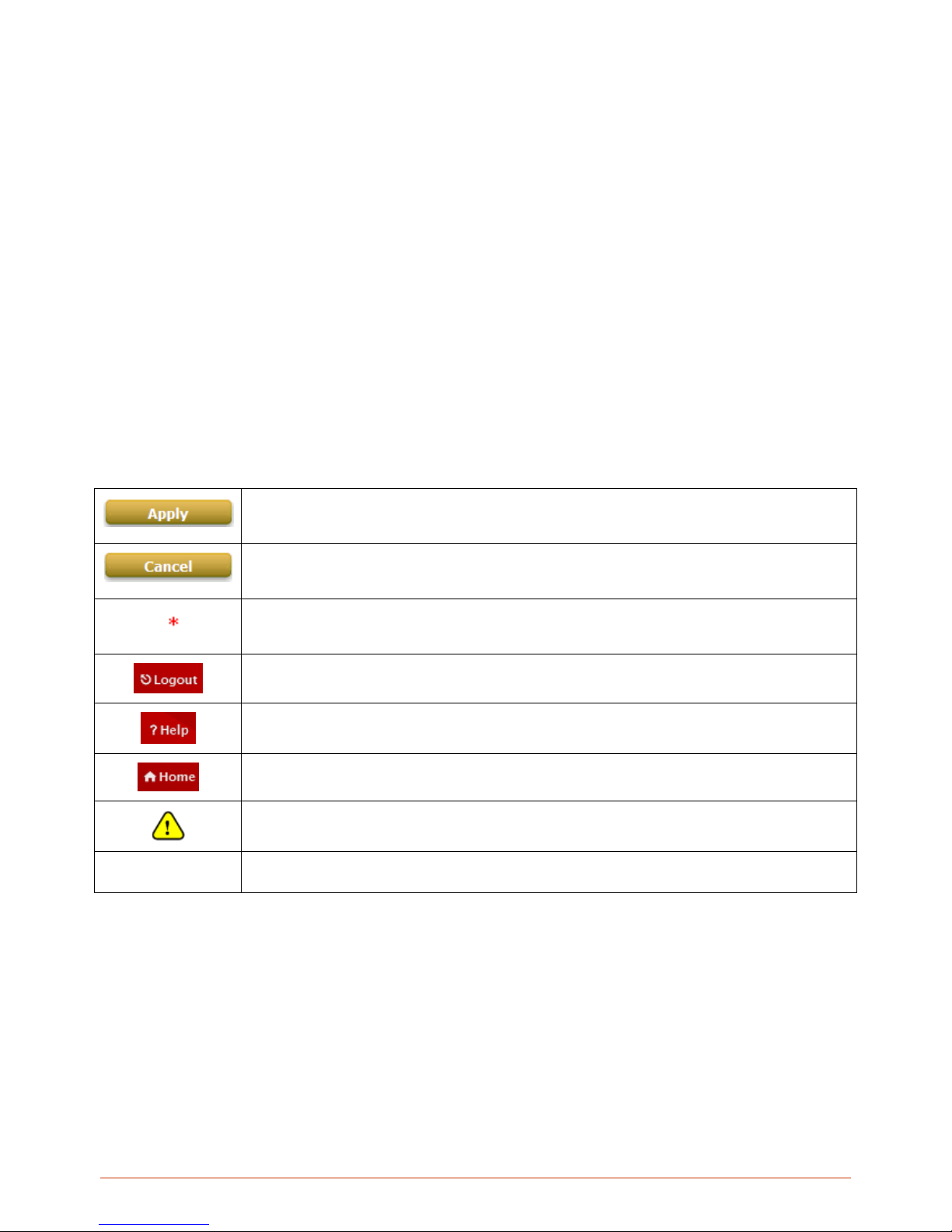
Indicates that clicking this button will apply all of your settings.
Indicates that clicking this button will clear what you have set before the settings are applied.
The red asterisk indicates that information in this field is compulsory.
Log out the system.
Access Online Help interface.
Access Home interface.
Represents essential steps, actions, or messages that should not be ignored.
Note:
Contains related information that corresponds to a topic.
Page 9

9
2. WHG Contro llers Installation Guide
2.1. WHG Controller Capacity Table
Capacity WHG-311 WHG-315 WHG-401 WHG-505 WHG-515 WHG-707
Form Factor
13" Mini-book 19”(1U) 19”(1U) 19”(1U) 19”(1U) 19”(1U)
WAN 2 x GbE 2 x GbE 2 x GbE 2 x GbE 2 x GbE
2 x GbE,
2 x Combo
SFP
LAN 8 x GbE 8 x GbE 2 x GbE 2 x GbE 4 x GbE
4 x GbE,
2 x SFP
Local
Accounts
3000 4000 5000 6000 10000 15000
On-demand
Accounts
3000 4000 5000 6000 10000 15000
Managed AP
Capacity
(Local & Wide
Combined)
30 50 150 200 250 500
LevelOne AP
Model
EAP-110
EAP-200
EAP-300
EAP-110
EAP-200
EAP-300
EAP-110
EAP-200
EAP-300
OWL800
EAP-110
EAP-200
EAP-300
OWL800
EAP-110
EAP-200
EAP-300
OWL800
EAP-110
EAP-200
EAP-300
OWL800
Monitored IP 100 100 200 200 250 500
Service Zones
Default + 8 Default + 8 Default + 8 Default + 8 Default + 8 Default + 8
User Groups 8 8 16 24 24 24
User Policies
Global + 12 Global +12 Global + 24 Global + 40 Global + 40 Global + 40
Page 10
10
2.2. WHG Controller Hardware Overview
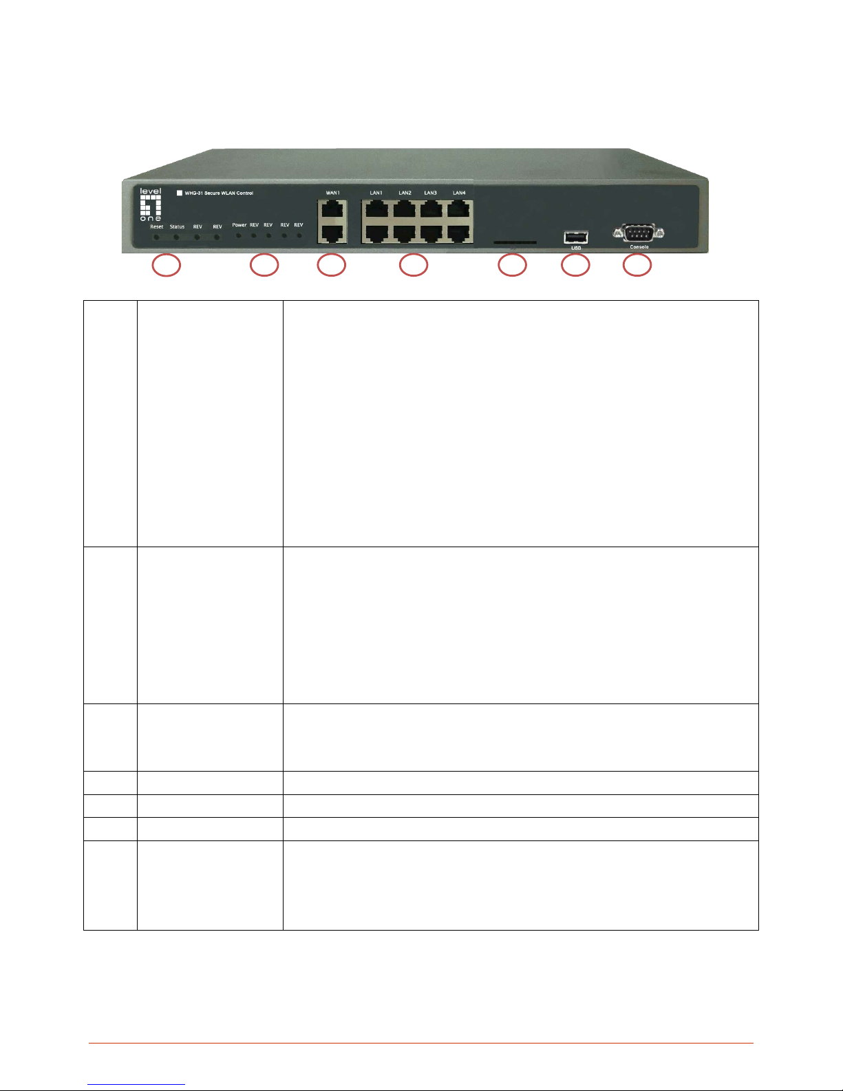
2.2.1. WHG-311 Hardware
1
Quick Buttons
Reset: Press and hold the Reset button for over 3 seconds and status of
LED on front panel will start to blink, release button at this stage to
restarting the system. Press and hold the Reset button for more than 10
seconds and status of LED on the front panel will turn from blinking to off,
release at this stage to reset the system to default configuration.
Quick-Restore: This button is the firmware switch button. Press this
button while system is powering up and release when the “Quick-Restore”
LED lights up, the system will switch to the other firmware image and boot
up with that firmware.
Quick-VPN: Function reserved for future release.
Quick-Offload: Function reserved for future release.
2
LED Displays
Power: Power LED lights up as constant green when power supply is on.
Status: Status LED is Blue. Blinking indicates that system OS is booting
up, when lit up constantly indicates that the system is ready for operation.
Quick-Restore: This is used to indicate that the system will now switch to
the other F/W partition for operation.
Quick-VPN: Function reserved for future release.
Quick-Offload: Function reserved for future release.
3
WAN1/ WAN2
Two Gigabit WAN ports (10/100/1000 Base-T RJ-45) for uplink connections to
the external network, such as the ADSL Router from your ISP (Internet Service
Provider).
4
LAN1~ LAN8
Eight Gigabit LAN ports for servicing LAN traffic (10/100/1000 Base-T RJ-45).
5
SD Disk
Used for system storage, please do not remove during operation.
6
USB
Function Reserved for future use.
7
Console
The system can be configured via a serial console port. The administrator can
use a terminal emulation program such as Microsoft’s Hyper Terminal to login to
the configuration console interface to change admin password or monitor system
status, etc.
1
2 3 4 5 6
7
Page 11
11
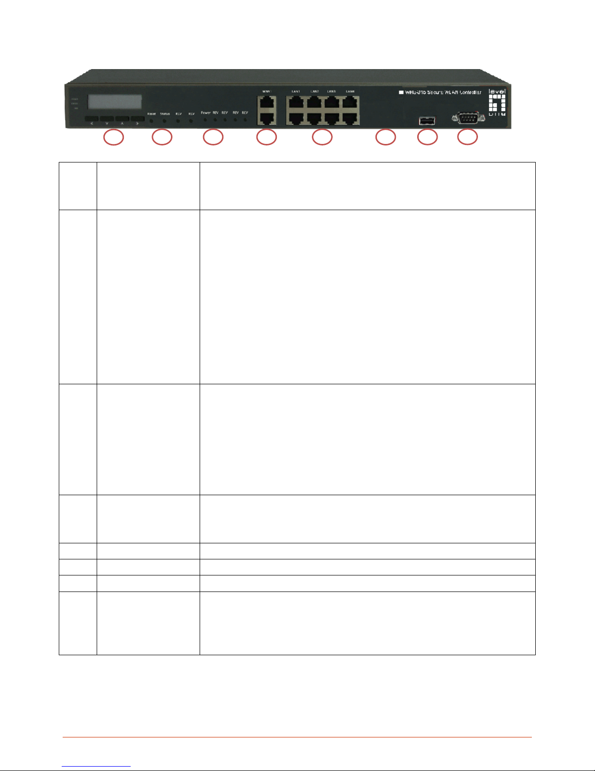
2.2.2. WHG-315 Hardware
1
LCD Display
Allows network administrator to check important system settings such as
network interface, SZ configurations, etc. The navigations buttons from left
to right respectively are “Sleep”, “Esc”, “Up”, “Down”, and “Enter”.
2
Quick Buttons
Reset: Press and hold the Reset button for over 3 seconds and status of
LED on front panel will start to blink, release button at this stage to
restarting the system. Press and hold the Reset button for more than 10
seconds and status of LED on the front panel will turn from blinking to off,
release at this stage to reset the system to default configuration.
Quick-Restore: This button is the firmware switch button. Press this
button while system is powering up and release when the “Quick-Restore”
LED lights up, the system will switch to the other firmware image and boot
up with that firmware.
Quick-VPN: Function reserved for future release.
Quick-Offload: Function reserved for future release.
3
LED Displays
Power:
Power LED lights up as constant green when power supply is on.
Status: Status LED is Blue. Blinking indicates that system OS is booting
up, when lit up constantly indicates that the system is ready for operation.
Quick-Restore: This is used to indicate that the system will now switch to
the other F/W partition for operation.
Quick-VPN: Function reserved for future release.
Quick-Offload: Function reserved for future release.
4
WAN1/ WAN2
Two Gigabit WAN ports (10/100/1000 Base-T RJ-45) for uplink connections to
the external network, such as the ADSL Router from your ISP (Internet Service
Provider).
5
LAN1~ LAN8
Eight Gigabit LAN ports for servicing LAN traffic (10/100/1000 Base-T RJ-45).
6
SD Disk
Used for system storage, please do not remove during operation.
7
USB
Function Reserved for future use.
8
Console
The system can be configured via a serial console port. The administrator can
use a terminal emulation program such as Microsoft’s Hyper Terminal to login to
the configuration console interface to change admin password or monitor system
status, etc.
1
2 3 4 5 6 7 8
Page 12
12
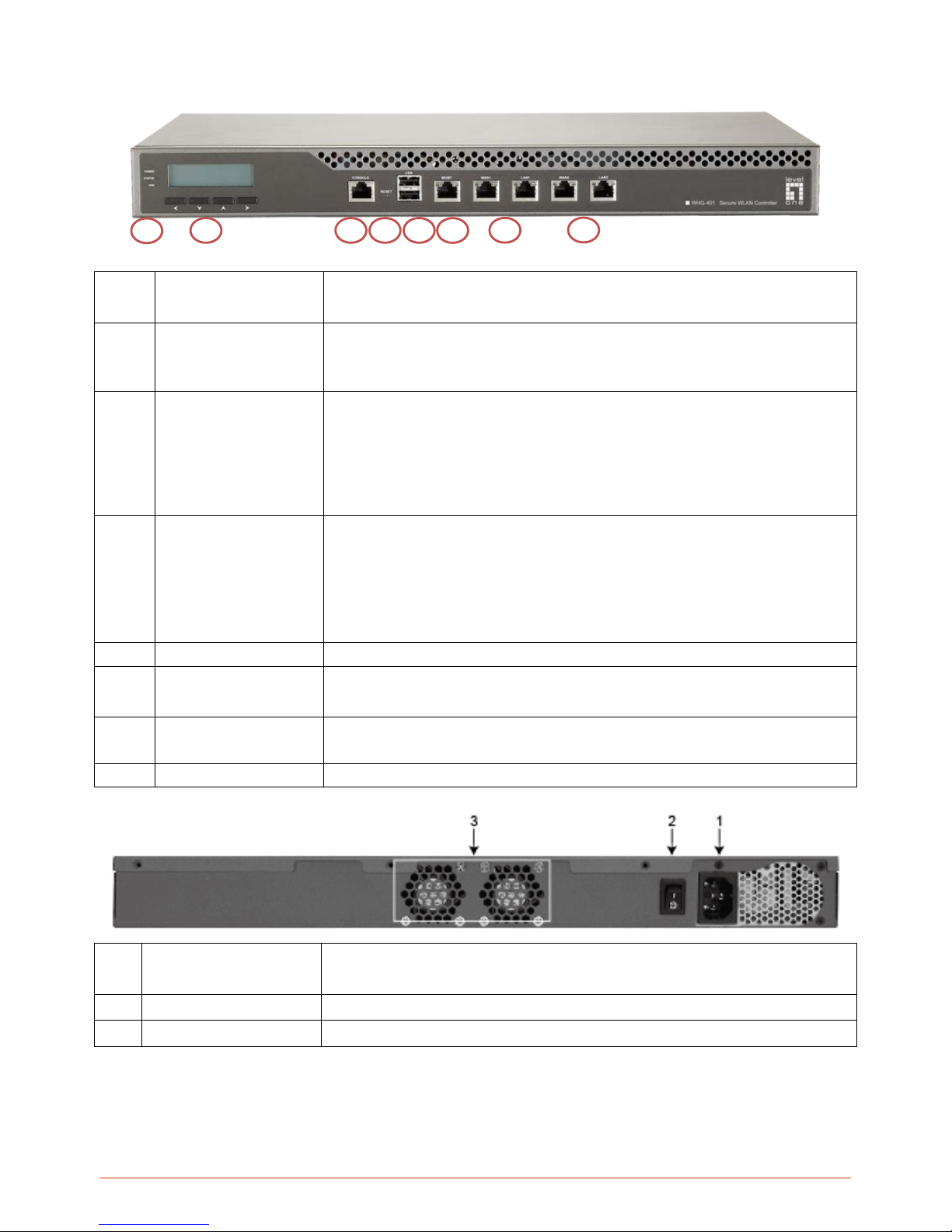
2.2.3. WHG-401 Hardware
1
LED Indicators
There are three kinds of LED,
Power, Status
and
Hard-disk
, to indicate
different status of the system.
2
LCD Display
Allows network administrator to check important system settings such as network
interface, SZ configurati ons, et c. T he navigat ion buttons from left to right respectively are
“Esc”, “Up”, “Down”, and “Enter”.
3
Console
The system can be configured via a serial console port. The administrator can
use a terminal emulation program such as Microsoft’s Hyper Terminal to login to
the configuration console interface to change admin password or monitor
system status, etc.
4
Reset
Press and hold the Reset button for about 5 seconds and status of LED on front
panel will start to blink before restarting the system.
Press and hold the Reset button for more than 10 seconds and status of LED
on the front panel will start to speed up blinking before resetting the system to
default configuration.
5
USB
Reserved for future use.
6
Mgmt
For management use only, it always will open WMI (Web Management
Interface) homepage.
7
WAN1/ WAN2
Two Gigabit WAN ports (10/100/1000 Base-T RJ-45) for uplink connections to the
external network, such as the ADSL Router from your ISP (Internet Service Provider).
8
LAN1/ LAN2
Two Gigabit LAN ports for servicing LAN traffic (10/100/1000 Base-T RJ-45).
1
Power Supply Socket
Connecting the power cord to the built-in open-frame power supply (Input:
100~240 VAC, 50/60 Hz).
2
Power Switch
Power-On () & Power-Off ( O ).
3
Device Cooling Fan
Don’t block the cooling fans. Leave enough open space for ventilation.
1 2 3 4 5 6 7
8
Page 13
13
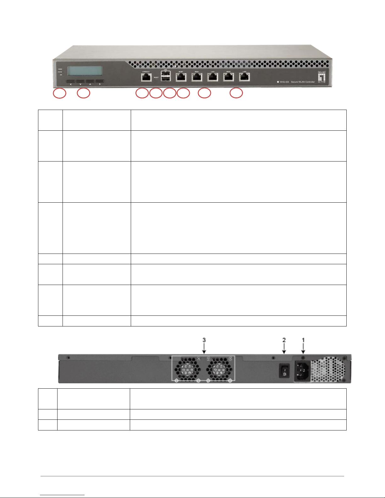
2.2.4. WHG-505 Hardware
1
LED Indicators
There are three kinds of LED,
Power, Status
and
Hard-disk
, to indicate
different status of the system.
2
LCD Display
Allows network administrator to check important system settings such as
network interface, SZ configurations, etc. The navigations buttons from left to
right respectively are “Esc”, “Up”, “Down”, and “Enter”.
3
Console
The system can be configured via a serial console port. The administrator can
use a terminal emulation program such as Microsoft’s Hyper Terminal to login to
the configuration console interface to change admin password or monitor
system status, etc.
4
Reset
Press and hold the Reset button for about 5 seconds and status of LED on front
panel will start to blink before restarting the system.
Press and hold the Reset button for more than 10 seconds and status of LED
on the front panel will start to speed up blinking before resetting the system to
default configuration.
5
USB
Reserved for future use.
6
Mgmt
For management use only, it always will open WMI (Web Management
Interface) homepage.
7
WAN1/ WAN2
Two Gigabit WAN ports (10/100/1000 Base-T RJ-45) for uplink connections to
the external network, such as the ADSL Router from your ISP (Internet Service
Provider).
8
LAN1/ LAN2
Two Gigabit LAN ports for servicing LAN traffic (10/100/1000 Base-T RJ-45).
1
Power Supply Socket
Connecting the power cord to the built-in open-frame power supply (Input:
100~240 VAC, 50/60 Hz).
2
Power Switch
Power-On () & Power-Off ( O ).
3
Device Cooling Fan
Don’t block the cooling fans. Leave enough open space for ventilation.
1 2 3 4 5 6 7
8
Page 14
14
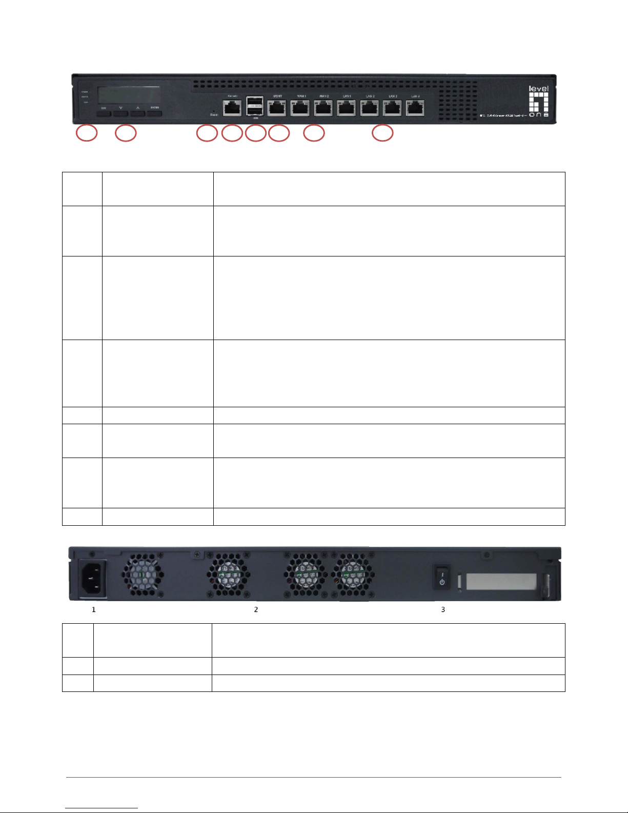
2.2.5. WHG-515 Hardware
1
LED Indicators
There are three kinds of LED, Power, Status and Hard-disk, to indicate
different status of the system.
2
LCD Display
Allows network administrator to check important system settings such as
network interface, SZ configurations, etc. The navigations buttons from left to
right respectively are “Esc”, “Up”, “Down”, and “Enter”.
3
Reset
Press and hold the Reset button for about 5 seconds and status of LED on front
panel will start to blink before restarting the system.
Press and hold the Reset button for more than 10 seconds and status of LED
on the front panel will start to speed up blinking before resetting the system to
default configuration.
4
Console
The system can be configured via a serial console port. The administrator can
use a terminal emulation program such as Microsoft’s Hyper Terminal to login to
the configuration console interface to change admin password or monitor
system status, etc.
5
USB
Reserved for future use.
6
Mgmt
For management use only, it always will open WMI (Web Management
Interface) homepage.
7
WAN1/ WAN2
Two Gigabit WAN ports (10/100/1000 Base-T RJ-45) for uplink connections to
the external network, such as the ADSL Router from your ISP (Internet Service
Provider).
8
LAN1 ~ LAN4
Four Gigabit LAN ports for servicing LAN traffic (10/100/1000 Base-T RJ-45).
1
Power Supply Socket
Connecting the power cord to the built-in open-frame power supply (Input:
100~240 VAC, 50/60 Hz).
2
Device Cooling Fan
Don’t block the cooling fans. Leave enough open space for ventilation.
3
Power Switch
Power-On () & Power-Off ( O ).
1 2 3 4 5 6 7
8
Page 15
15
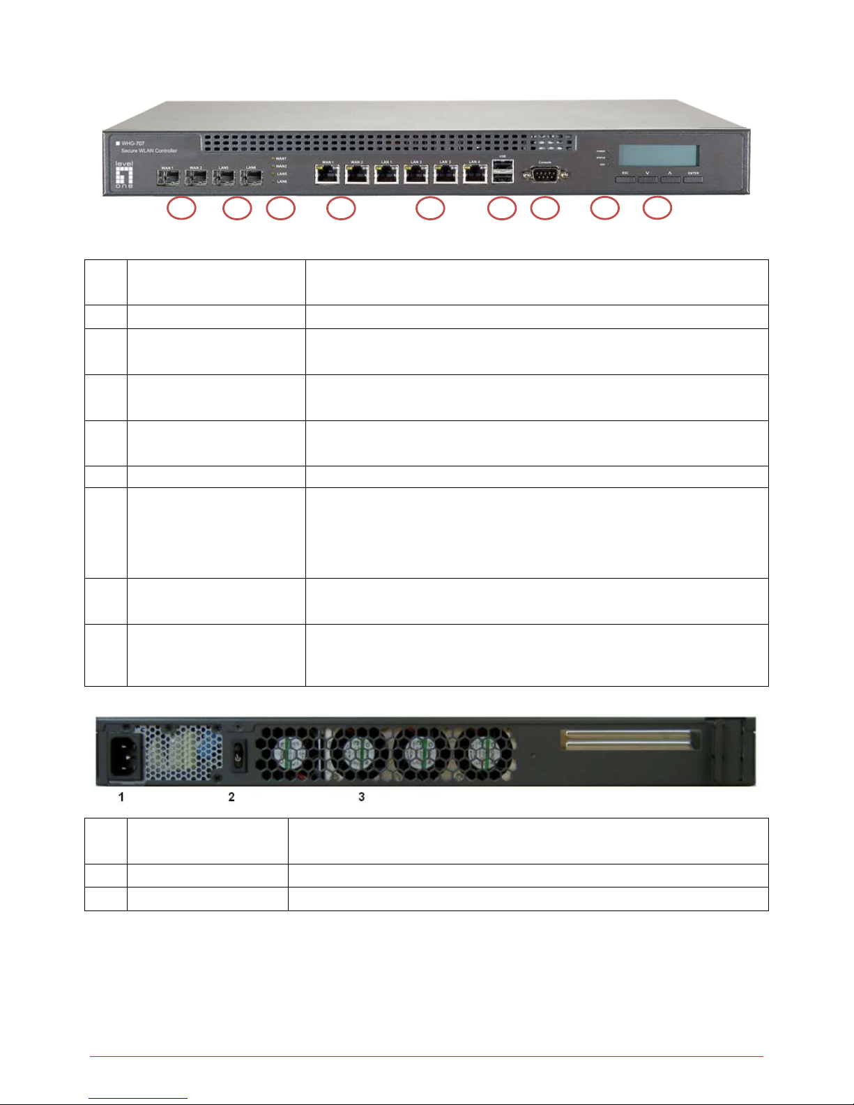
2.2.6. WHG-707 Hardware
1
WAN1/ WAN2 (SFP)
Two combo WAN ports (SFP) are connected to the external network, such as
the ADSL Router from your ISP (Internet Service Provider).
2
LAN5/ LAN6 (SFP)
Client machines connect to WHG Controller via these LAN ports (SFP).
3
LED Indicators
There are four kinds of LED, WAN1, WAN2, LAN4, and LAN5, to indicate the
traffic status of the SFP ports.
4
WAN1/ WAN2
Two WAN ports (10/100/1000 Base-T RJ-45) are connected to the external
network, such as the ADSL Router from your ISP (Internet Service Provider).
5
LAN1 ~ LAN4
Client machines connect to WHG Controller via these LAN ports
(10/100/1000 Base-T RJ-45).
6
USB
Reserved for future use.
7
Console
The system can be configured via a serial console port. The administrator can
use a terminal emulation program such as Microsoft’s Hyper Terminal to login
to the configuration console interface to change admin password or monitor
system status, etc.
8
LED Indicators
There are three kinds of LED, Power, Status and Hard-disk, to indicate
different status of the system.
9
LCD Display
Allows network administrator to check important system settings such as network
interface, SZ configurations, etc. The navigations buttons from left to right respectively
are “Esc”, “Up”, “Down”, and “Enter”.
1
Power Supply Socket
Connecting the power cord to the built-in open-frame power supply (Input:
100~240 VAC, 50/60 Hz).
2
Power Switch
Power-On () & Power-Off ( O ).
3
Device Cooling Fan
Don’t block the cooling fans. Leave enough open space for ventilation.
1 2 3 4 5 6 7 8 9
Page 16

16
2.3. Preparation before the Installation
Before you start the installation by either following this User Manual or the Quick Installation Guide, below is a short
preparation list to do.
1. Unpack the WHG Controller and go through the package checklist.
2. Revie w the front panel and the back panel and identif y each control and networ k interface that is descr ibed in
the Hardware & Specification section.
3. Prepare Ethernet cables with RJ-45 connectors.
4. Prepare a PC with Web browser for accessing the Web Management Interface.
5. Identify an upstream device for WHG Controller to connect to in your network, such as ADSL, CABLE modem or
other edge devices. Collect the DNS server address provided by your ISP.
If you are using WHG Controller product for th e first tim e, it is recommended tha t you follow the Quick Installation
Guide to start up the WHG Control ler in a near default state with m inimum configuration changes (such as WAN
settings and adm in password), then refer t o this manual later when you want to configure the system for specif ic
application needs.
The recommended general steps for the configuration are:
Set up system’s Time Zone, NTP server, DNS server and WAN1 address
Configure LAN address range for at least one Service Zone, and enable its authentication. The
Default Service Zone is enabled to require authentication by the factory default.
Create user accounts to test the login page via wire line in the enabled Service Zone.
Try to generate on-demand user and test the account.
Configure Wireless Settings of Service Zone, then add in AP.
Configure more Service Zones base on your application.
Set up Group and Policy (including Firewall rules and Session Limit).
Customize the portal login page and add walled garden Advertisement links if needed.
Set up Payment gateway if you want to use credit card for the on-demand accounts.
Load SSL certificate for the Web Server before operation.
Monitor the status pages and reports generated.
Perform other advanced setting for your specific application.
Page 17

17
2.4. Unpacking & Installing
2.4.1. WHG-311 Package & Installation
Package Checklist
The standard package of WHG-311 includes:
WHG-311 x 1
CD-ROM (with User’s Manual and QIG ) x 1
Quick Installation Guide (QIG) x 1
RS-232 DB9 Console Cable x 1
Ethernet Cable x 1
Power Adaptor (12VDC, 2A) x 1
It is highly recommended to use all the supplies in the package instead of substituting any components by
other suppliers to guarantee best performance.
Installation
Connect the power adaptor to the power socket on the rear panel. The Power LED should be on to indicate a
proper connection.
Connect an Ethernet cable to the WAN1 Port on the front panel. Connect the other end of the Ethernet cable to
an xDSL/cable modem, or a switch/hub of an internal network. The LED of this port should be on to indicate a
proper connection.
Connect an Ethernet cable to a LAN Port on the front panel. Connect the other end of the Ethernet cable to an
administrator PC for configuring the system. Connect an Ethernet cable to the LAN1 or LAN2 Port on the front
panel. Connect the other end of the Ethernet cable to an AP for extending wireless coverage; a switch for
connecting more wired clients; or directly to a client PC. The LED of port should be on to indicate a proper
connection.
2.4.2. WHG-315 Package & Installation
Package Checklist
The standard package of WHG-315 includes:
WHG-315 x 1
CD-ROM (with User’s Manual and QIG ) x 1
Quick Installation Guide (QIG) x 1
RS-232 DB9 Console Cable x 1
Ethernet Cable x 1
Power Cord x 1
Page 18
18
Rack Mounting Bracket (with Screws) x 1
It is highly recommended to use all the supplies in the package instead of substituting any components by
other suppliers to guarantee best performance.
Installation
Connect the power cord to the power socket on the rear panel.
Turn on ( | ) the power switch on the rear panel. The Power LED should be on to indicate a proper connection.
Connect an Ethernet cable to the WAN1 Port on the front panel. Connect the other end of the Ethernet cable to
an xDSL/cable modem, or a switch/hub of an internal network. The LED of this port should be on to indicate a
proper connection.
Connect an Ethernet cable to a LAN Port on the front panel. Connect the other end of the Ethernet cable to an
administrator PC for configuring the system. Connect an Ethernet cable to the LAN1 or LAN2 Port on the front
panel. Connect the other end of the Ethernet cable to an AP for extending wireless coverage; a switch for
connecting more wired clients; or directly to a client PC. The LED of port should be on to indicate a proper
connection.
2.4.3. WHG-401 Package & Installation
Package Checklist
The standard package of WHG-401 includes:
WHG-401 x 1
CD-ROM ( with User’s Manual and QIG) x 1
Quick Installation Guide (QIG) x 1
RS-232 DB9 to RJ45 Console Cable x 1
Ethernet Cable x 1
Straight-through Ethernet Cable x 1
Power Cord x 1
Rack Mounting Bracket (with Screws) x 1
It is highly recommended to use all the supplies in the package instead of substituting any components by
other suppliers to guarantee best performance.
Installation
Connect the power cord to the power socket on the rear panel.
Turn on ( | ) the power switch on the rear panel. The Power LED should be on to indicate a proper connection.
Connect an Ethernet cable to the WAN1 Port on the front panel. Connect the other end of the Ethernet cable to
an xDSL/cable modem, or a switch/hub of an internal network. The LED of this port should be on to indicate a
proper connection.
Connect an Ethernet cable to the Mgmt Port on the front panel. Connect the other end of the Ethernet cable to
an administrator PC for configuring the system. Connect an Ethernet cable to the LAN1 or LAN2 Port on the
front panel. Connect the other end of the Ethernet cable to an AP for extending wireless coverage; a switch for
Page 19

19
connecting more wired clients; or directly to a client PC. The LED of port should be on to indicate a proper
connection.
2.4.4. WHG-505 Package & Installation
Package Checklist
The standard package of WHG-505 includes:
WHG-505 x 1
CD-ROM ( with User’s Manual and QIG) x 1
Quick Installation Guide (QIG) x 1
RS-232 DB9 to RJ45 Console Cable x 1
Ethernet Cable x 1
Straight-through Ethernet Cable x 1
Power Cord x 1
Rack Mounting Bracket (with Screws) x 1
It is highly recommended to use all the supplies in the package instead of substituting any components by
other suppliers to guarantee best performance.
Installation
1. Connect the power cord to the power socket on the rear panel.
2. Turn on ( | ) the power switch on the rear panel. The Power LED should be on to indicate a proper
connection.
3. Connect an Ethernet cable to the WAN1 Port on the front panel. Connect the other end of the Ethernet cable
to an xDSL/cable modem, or a switch/hub of an internal network. The LED of this port s hou ld be on to
indicate a proper connection.
4. Connect an Ethernet cable to the Mgmt Port on the front panel. Connect the other end of the Ethernet cable
to an administrator PC for configuring the system. Connect an Ethernet cable to the LAN1 or LA N 2 Port on
the front panel. Connect the other end of the Ethernet cable to an AP for extending wireless coverage; a
switch for connecting more wired clients; or directly to a client PC. The LED of port should be on to indicate
a proper connection.
2.4.5. WHG-515 Package & Installation
Package Checklist
The standard package of WHG-505 includes:
WHG-515 x 1
CD-ROM ( with User’s Manual and QIG) x 1
Quick Installation Guide (QIG) x 1
RS-232 DB9 to RJ45 Console Cable x 1
Page 20
20
Ethernet Cable x 1
Straight-through Ethernet Cable x 1
Power Cord x 1
Rack Mounting Bracket (with Screws) x 1
It is highly recommended to use all the supplies in the package instead of substituting any components by
other suppliers to guarantee best performance.
Installation
Connect the power cord to the power socket on the rear panel.
Turn on ( | ) the power switch on the rear panel. The Power LED should be on to indicate a proper connection.
Connect an Ethernet cable to the WAN1 Port on the front panel. Connect the other end of the Ethernet cable to
an xDSL/cable modem, or a switch/hub of an internal network. The LED of this port should be on to indicate a
proper connection.
Connect an Ethernet cable to the Mgmt Port on the front panel. Connect the other end of the Ethernet cable to
an administrator PC for configuring the system. Connect an Ethernet cable to the LAN1 or LAN2 Port on the
front panel. Connect the other end of the Ethernet cable to an AP for extending wireless coverage; a switch for
connecting more wired clients; or directly to a client PC. The LED of port should be on to indicate a proper
connection.
2.4.6. WHG-707 Package & Installation
Package Checklist
The standard package of WHG-707 includes:
WHG-707 x 1
CD-ROM (with User’s Manual and QIG) x 1
Quick Installation Guide (QIG) x 1
RS-232 DB9 Console Cable x 1
Ethernet Cable x 2
Power Cord x 1
Rack Mounting Bracket (with Screws) x 1
It is highly recommended to use all the supplies in the package instead of substituting any components by
other suppliers to guarantee best performance.
Installation
1. Connect the power cord to the power socket on the rear panel.
2. Turn on the power switch on the rear panel.
3. Connect an Ethernet cable to the WAN1 Port on the front panel. Connect the other end of the Ethernet cable
to an xDSL/cable modem, or a switch/hub of an internal network. The LED of this port should be on to
indicate a proper connection.
4. Connect an Ethernet cable to the LAN Ports on the front panel; connect the other end of the Ethernet cable
Page 21
21
to an administrator PC for configuring the WHG Controller system. Connect an Ethernet c ab le to the LAN 1
or LAN2 Port on the front panel; connect the other end of the Ethernet cable to an AP for extending wireless
coverage, a switch for connecting more wired clients, or a client PC. The LED of this port should be on to
indicate a proper connection.
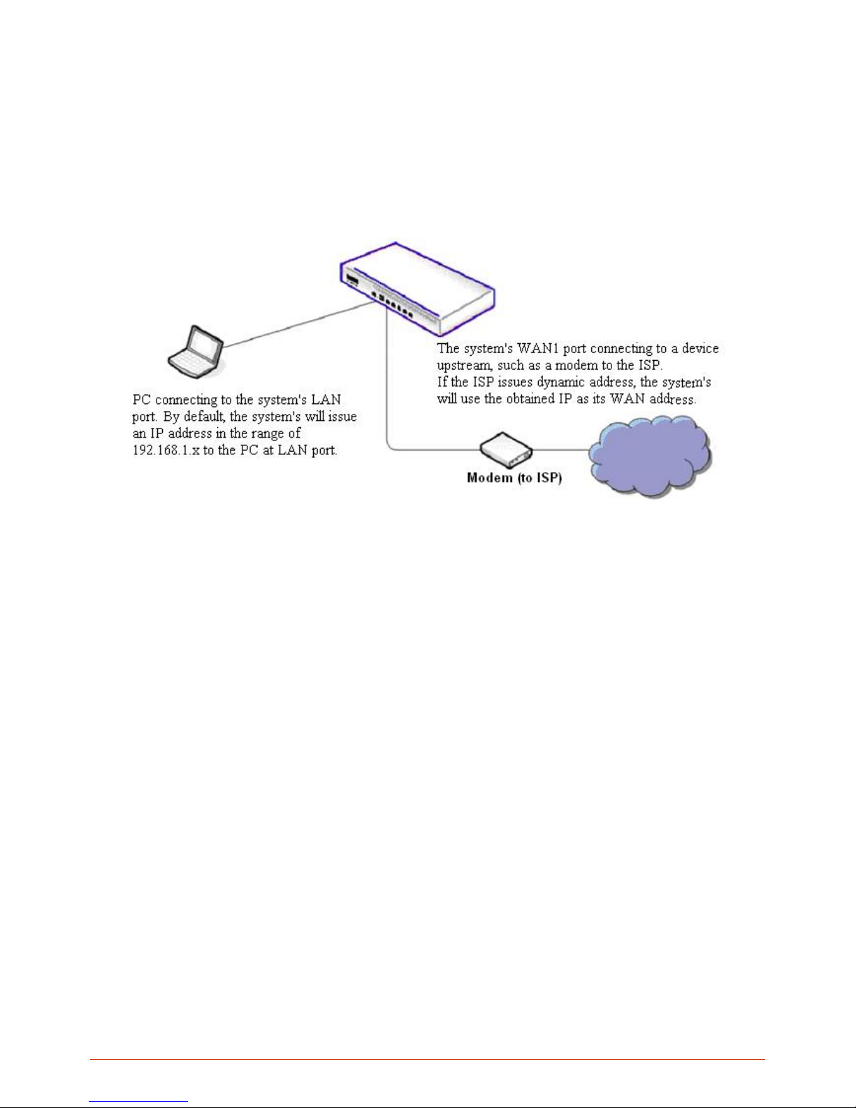
Start with this simple network topology to set up WHG Controller for the first time; it helps to plan a more
sophisticated network topology to suits your specific application needs later.
【
A simple network diagram for the initial setup】
Page 22

22
3. System Overview
3.1. System Concept
If you have experienced other LevelOne WLAN WHG Controller products before and are familiar with its system
concept, you may skip the concept description below. Please proceed to the next section on (Getting Started).
WHG Controller is capable of managing user authentication, authorization and accounting (AAA). The user account
information is stored in the local database or a specified external database server. Featured with user authentication
and integrated with external payment gat e wa y, WHG Controllers allows users to easily pay the fee and enjoy the
Internet service using credit cards through Authorize.Net, PayPal, SecurePay, or WorldPay.
With centralized AP management feature, the administrator does not need to worry about how to manage multiple
wireless access point devices. WHG Controllers and LevelOne APs combined provides flexible network solution
which supports overlay deployment where traffics from remote sites are tunnelled back and centrally controlled by
WHG Controller.
Furthermore, WHG Controller introduces the concept of Service Zones - multiple virtual networks, each with its own
definable access control profiles. This is very useful for hotspot owners seeking to provide different customers or
staff with different levels of network services.
The following portion of this section explains the basic concepts of WHG Controller. With the understanding of these
concepts, the administrator will be able to do more advanced network planning and to manipulate the configurations
of WHG Controller to suit his own specific application. It is sufficient for most of administrators to use the default
configuration with minor WAN/DNS address changes for simple deployments.
Gateway is a network node where a small network attaches to a bigger networ k. WHG Controller is a kind of
gateway in a network environment; hence it has those features a typical gateway has, such as NAT, DHCP, DMZ,
Firewall and etc. Conventionally, the bigger network is referred as the gateway’s WAN side or upstream network,
while the small network is referred as the gateway’s LAN side. The Ethernet ports leading to the WAN side network
is called WAN ports. The Ethernet ports leading to the LAN side network is called LAN ports.
Local User is a type of user with its account credential stored in a b u ilt -in database named “Local” within WHG
Controller. The WHG Controller’s “Local” database cap ac it y varies with differ ent m ode l. A local user account does
not have an expiration date once they are created. If administrator wishes to terminate the account, he must remove
it manually from the database. A local database can be used as an external RADIUS database for another WHG
Controller product for account roaming.
On-demand User is a type of user with its account credential stored in a built-in database named “On-demand”
within WHG Controller. The WHG Controller’s “On-demand” database capacit y varies with different m odel. .
On-demand User is used for short term usage purpose; it has an expiration period. An on-demand account record
will be recycled for creating new on-demand account if it has expired for over 15 days or has been deleted by the
Page 23

23
Administrator/Manager manually.
External Authenticati on Database is a user account database that is not built inside WHG Controller. Besides
Local database and On-demand database, WHG Controller allows up to three additional External Authentication
databases simultaneously. The types of external Authentication databases supported are RADIUS, POP3, LDAP
(including Active Directory), and NTDomain (Win2K’s NTDS). The database of another WHG Controller device can
be used as an external RADIUS database. External Authentication Database is useful for implementing account
roaming; for example, multiple WHG Controller devices in multiple campuses can share one common external
database. A user needs only one account in the common database to access the network from different campuses.
Service Zone is a logic partition of WHG Controller’s LAN network. The concept of Service Zone is similar to the
concept of virtual LAN (VLAN), which can be used to group the network traffic or network services for clients on the
same VLAN segment, regardless of the clients’ physical locations. That is, several VLAN segments may be in
service at one physical network location as well as devices belonging to one VLAN segment may spread across
multiple physical locations.
Each Service Zone can also be viewed a virtual machine of WHG Controller because each Service Zone can define
its own customized login portal page, and its own gateway properties (such as LAN IP address, DHCP on/off and
address range). The feature of Multiple Service Zone is also useful to service multiple hotspot franchises in
shopping malls or airport terminals by a single WHG Controller.
A Service Zone is uniquely defined by a VLAN tag id (under Tag-Based) and an associated SSID attribute. When a
managed access point (MAP) is added to a Service Zone through WHG Controller’s AP Management feature by the
administrator, the associated SSID will be activated in the MAP along with the VLAN tag of the corresponding
Service Zone.
For example, in the following Figure 2, the administrator plans three logical Service Zones for an academic campus:
The first Service Zone (with SSID=’Student”, and VLAN tag=1) is for students.
The second (with SSID=”Faculty” and VLAN tag=2) for faculties.
The third (SSID=”Guest” and VLAN tag=3) for guests.
A Service Zone may or may not require client authentication, depending on how the administrator sets it up. If a
Service Zone requires user authentication, the client will be prompted for the login in first before using the network
services, no matter whether the client is connecting to its SSID wirelessly or a switch port via wired line,.
Group is a group of user accounts sharing the same access privileges, QoS properties and network policies. Each
client account belongs to a Group. Each Group may or may not be allowed to access a particular Service Zone,
depending on the how the administrator define its access mapping. If the administrator does not assign a new
account to any specific Group, the account belongs to a catch-all group named “None” by default.
Policy is for defining rules, privileges or properties for managing users . Each user group is bound by a Policy within
a given Service Zone. The same group may or may not be bound to the same policy in different Service zones.
There are two tiers of Policies. The first tier is a policy named ‘Global-Policy’. The Global-Po licy i s a base policy
which will be applied to all user s if not applied with another policy. The second tier is called ‘Group-Policy’ or simply
Page 24
24
‘Policy’, whic h can be chosen to bound the network behaviors of a Group. The administrator can define the Firewall
Profile, Route Profile, Schedule Profile and Max Sessions in a Policy.
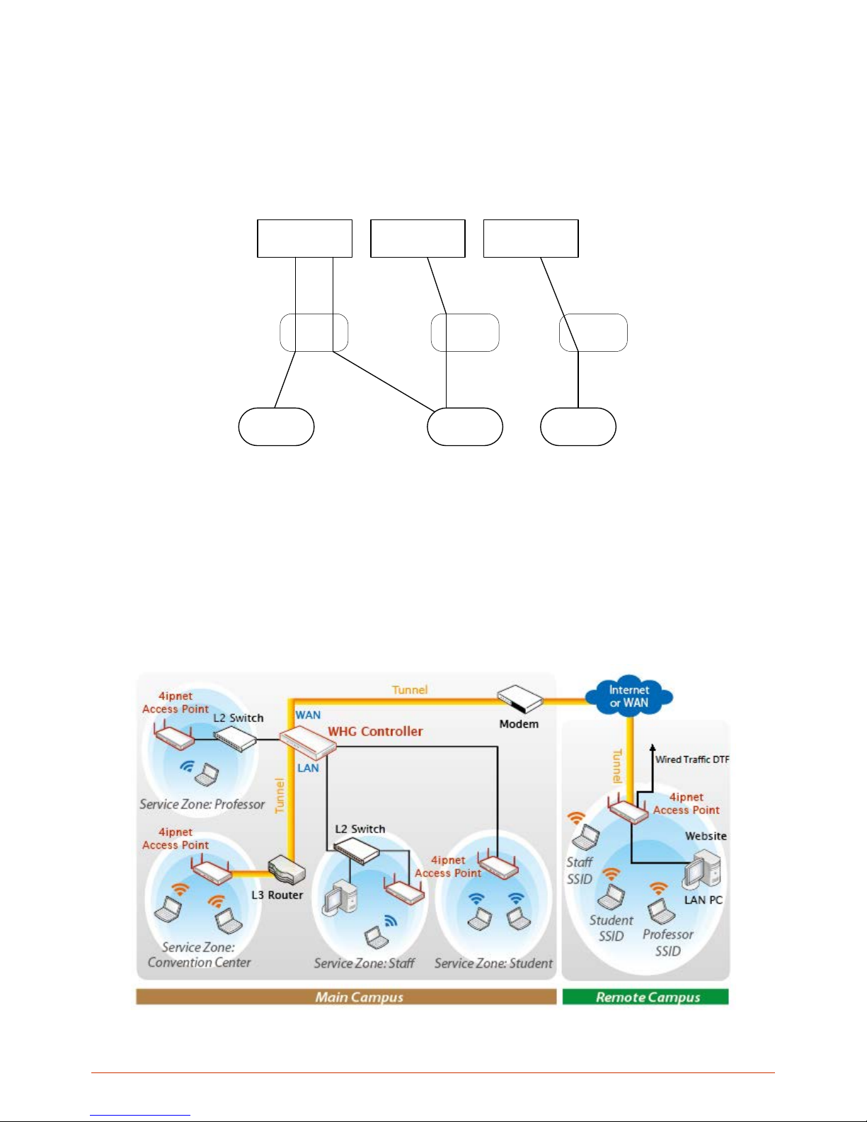
The following Figure depicts an example relationship of Service Zone, Group and Policy. In this example, Students
and faculties logging into Service Zone 1 will be governed by Policy-A. Guests only have the access of Service Zone
3, and will be bounded by Policy-C. Faculties have the access to both Service Zone 1 and Service Zone 2 under two
different policies.
An example relationship of Service Zone, Group and Policy
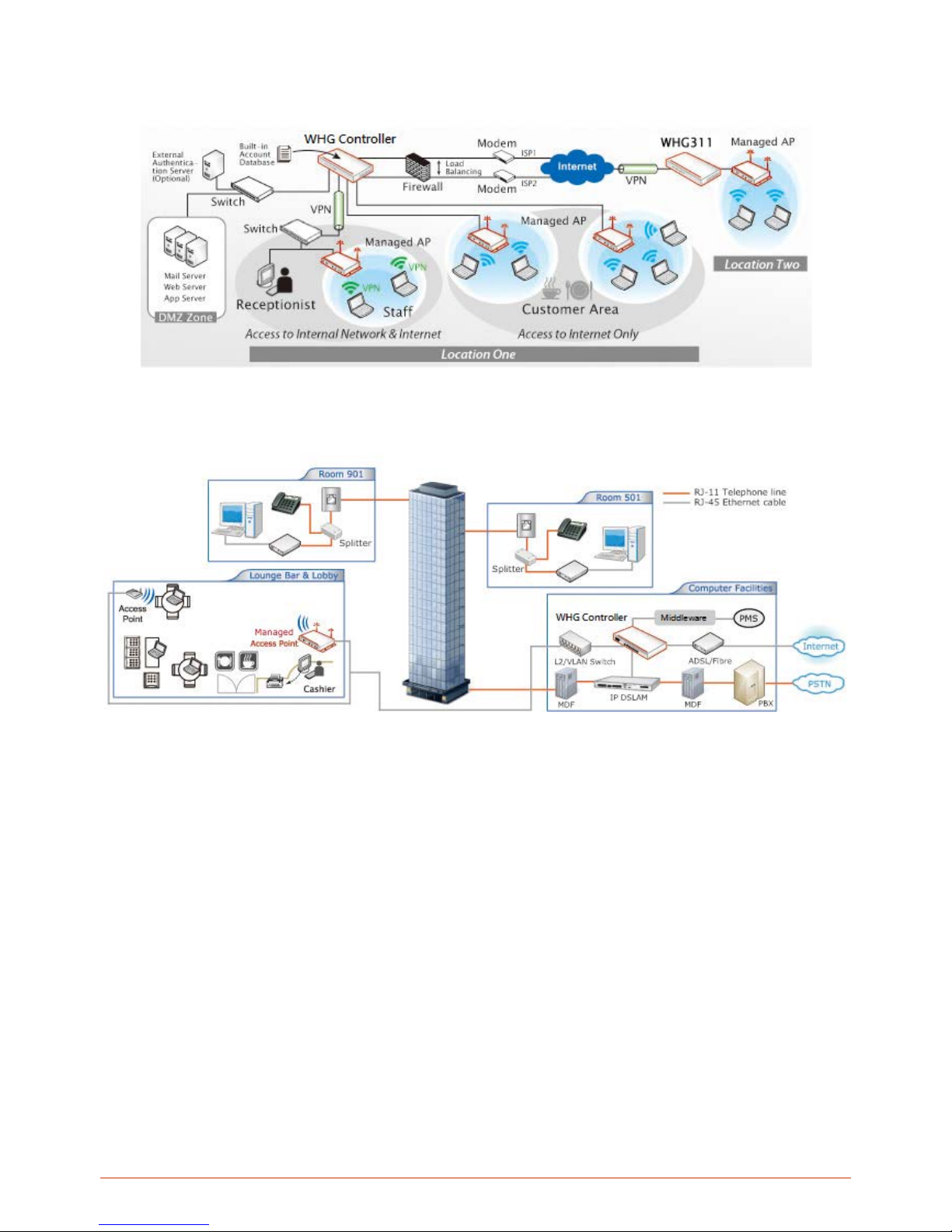
The following Figure depicts an example using WHG Controller in managing network/internet access i n an academic
campus environment. Imagine the network administrator may wish to set different privileges and bandwidth limits for
staff, students, and professors; he could use several Service Zones of WHG Controller – one for staff, one for
students, and one for the professors. He also uses one zone for some shared servers in the diagram.
There traffic of students, professors, and guests can be segregated by thereby different VLAN segments.
An example of managed network in a Campus environment
Service Zone 1
Service Zone 2
Service Zone 3
Policy-B
Group
Student
Group
Faculty
Group
Guest
Policy-C
Policy-A
Page 25
25
WHG Controller in a Business Headquarter
WHG Controller in a Hotel – Capable of integrating with DSLAM and PMS
Page 26
26
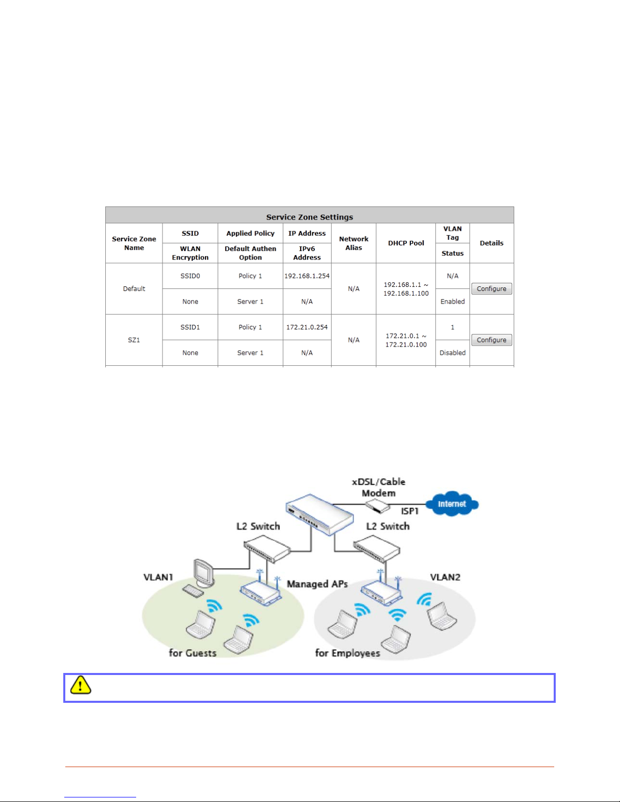
3.2. Service Zone Concept
LevelOne Service Zones are virtual machines that has its’ own network interface, DHCP server, authentication
configuration, user pages as well as security and user policy settings.
By associating a unique VLAN Tag and SSID with a Service Zone, administrators can separate wired net w ork and
wireless network into different logical networks isolated from one another. Users attempting to access the resources
within the Service Zone will be controlled based on the access control profile of the Service Zone, such as
authentication, security feature, wireless encryption method, traffic control, and etc.
There are nine Service Zone profiles in total, Default Service Zone and Service Zones 1 ~ 8.
Simple network environment
For most simple internal network, such as there are just only two subnets. Using Port-Based model is an easy
and better way. In Port-Based mode (configurable in Port Location Mapping tab page), each LAN port can only
serve traffic from one Service Zone. An example of network application diagram is shown as below: one Service
Zone for Employees and one for Guests.
The switches deployed under Controller in Port-Based mode must be Layer 2 switches only.
Page 27
27
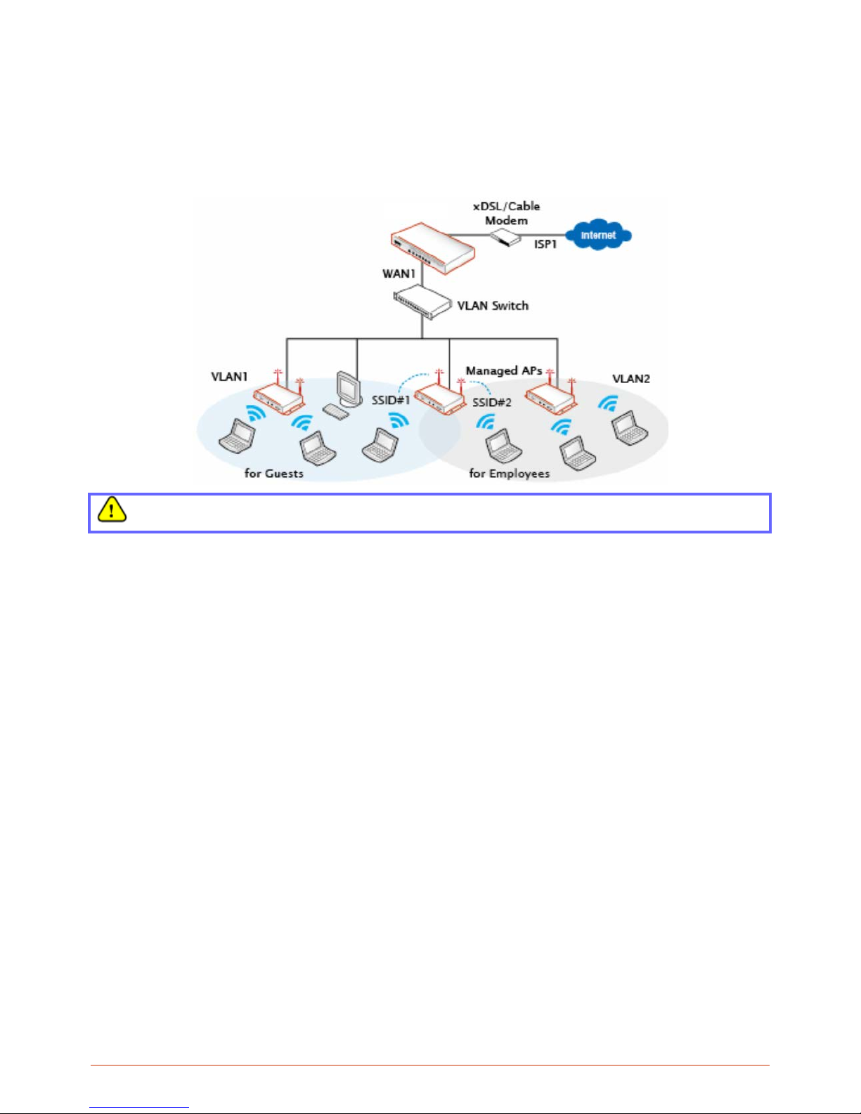
Multi subnet network environment
On the other hand, if the internal network is a Multi subnets network enviro nment, Tag-Based model will satisfy to
your conditions. In Tag-Based mode, each LAN port will serve traffics from different Service Zones; a VLAN switch
or VLAN AP is required to take care of the VLAN tags carried within the message frames.
An example of network application diagram is shown as below: more than two Service Zones for different
departments.
The switch deployed under Controller in Tag-Based mode must be a VLAN switch only.
Page 28
28
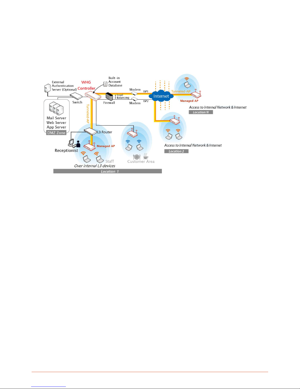
3.3. AP Management Concept
AP Management feature is designed not only for internal network AP deployment, but also overlay deployment at
remote locations over the cloud.
WHG Controllers can manage from 30 to 500 LevelOne Access Points depending on model. For overlay AP
deployment, WHG Controllers establish a secure tunnel between the managed AP and Controller.
Certain AP models with additional Ethernet ports can also provide wired network service. When managed remotely
over the internet, the APs wired user traffic can be forwarded into the internet without having to be tunneled back
and centrally forwarded by the AC. This feature is an example of Distributed Traffic Forwarding (DTF).
Page 29

29
4. Getti ng Started
4.1. Accessing Web Management Interf ace
When you have completed the hardware installation of your WHG Controller, system configurations can be
performed via built-in Web Management Interface (WMI).
Step 1. Connect your PC to any of the LAN ports of your WHG Controller.
Step 2. Set the TCP/IP settings on your PC to “Obtain an IP address automatically”.
Step 3. Launch a web browser and enter the WHG Controller’s default LAN IP address “192.168.1.254”. If you are
connected to a Mgmt port (WHG-401, WHG-505, WHG-515) please enter the mgmt port IP address “172.30.0.1”.
Step4. Enter the default administrator account and password “admin” to login. Once logged into the WMI, the
system’s Home Page will be displayed.
If your PC is connecting to the LAN port, and you can’t get the Administrator’s login screen, the reasons may be:
(1) The PC is set incorrectly so that the PC can’t obtain the IP address automatically from the built-in DHCP Server;
(2) The IP address and the default gateway are not under the same network segment.
Please use default IP address such as 192.168.1.xx in your netw ork and then tr y agai n.
Page 30
30
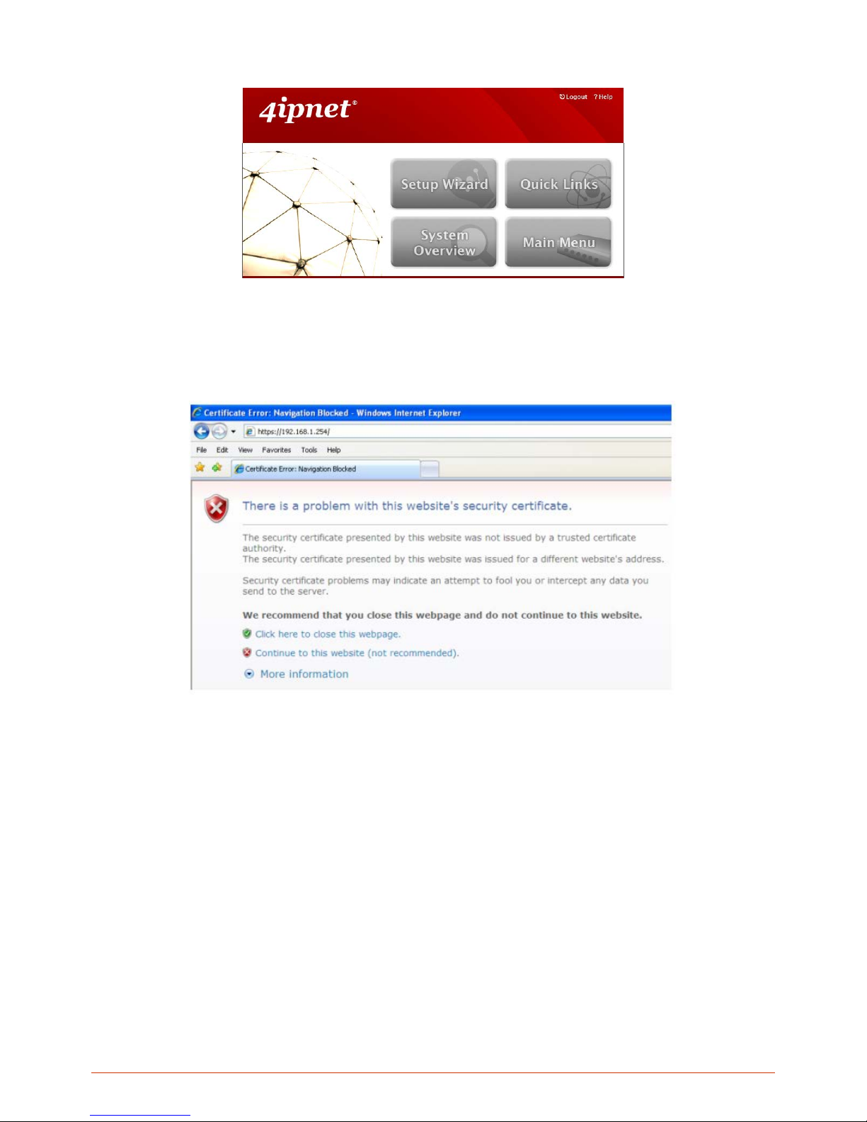
After a successful login, a Home Page will appear on the screen.
For the first time, if WHG Controller is not using a trusted SSL certificate, there will be a “Certificate Error”,
because the browser treats WHG Controller as an illegal website. Please press “Continue to this website” to
continue. The default user login page will then appear in the browser.
Page 31
31
4.2. Home Page
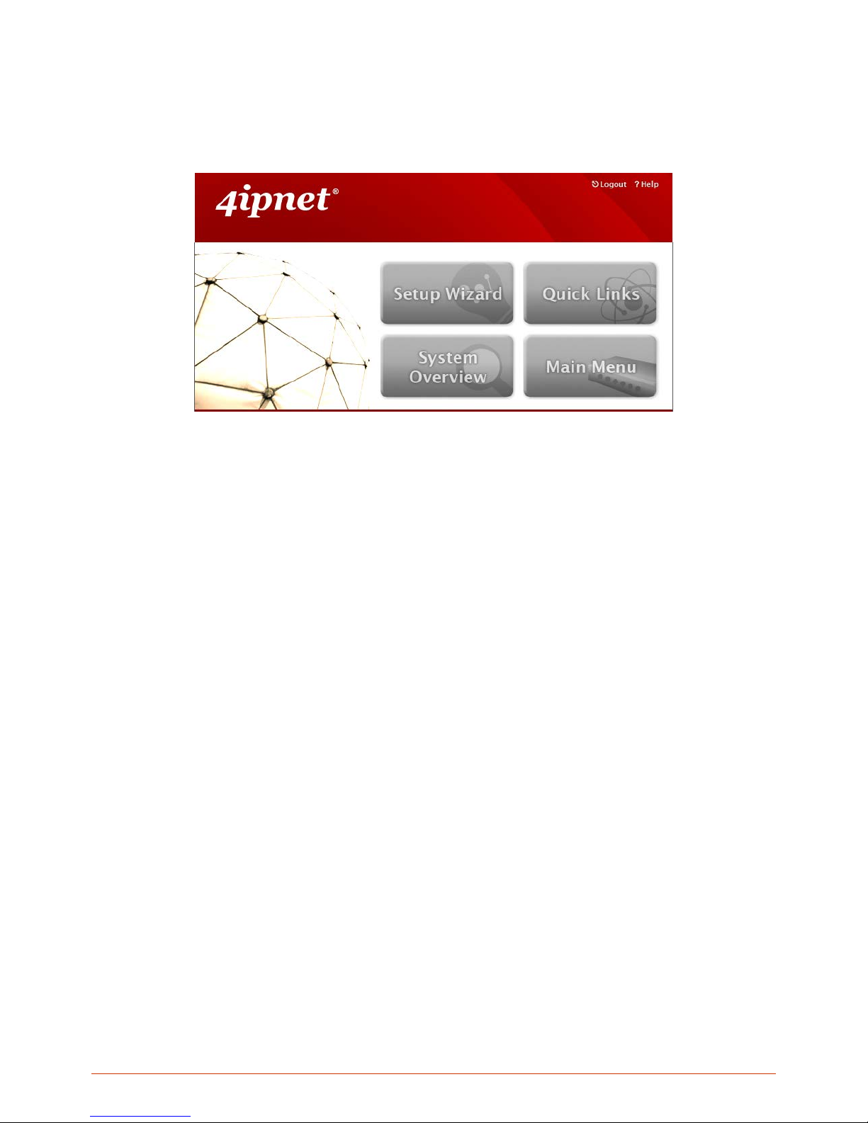
Home page lists four buttons Setup Wizard, Quick Links, System Overview and Main Menu respectively.
Each button will be described in detail in the following section.
Page 32
32
4.2.1. Setup Wizard
Using the configuration wizard
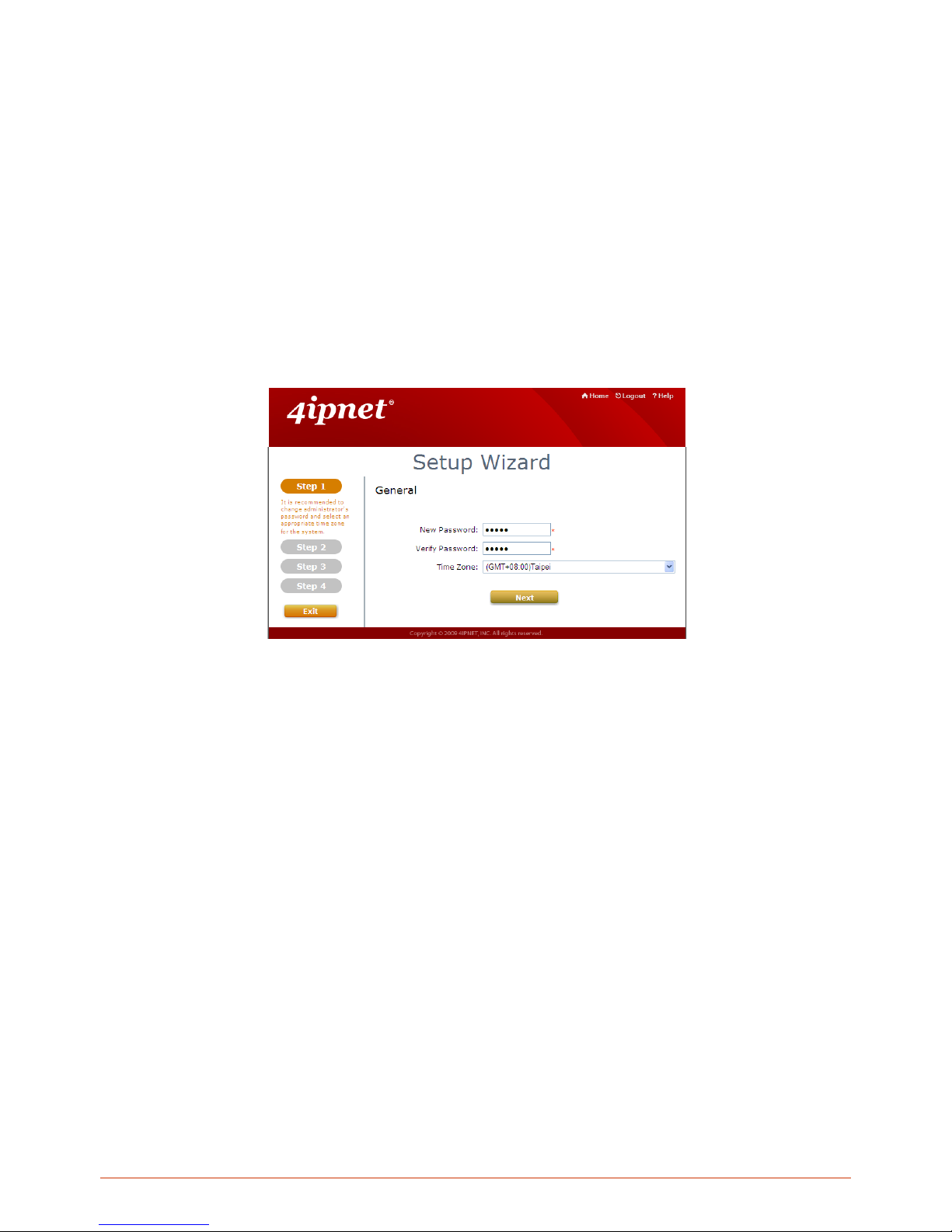
Configuration wizard provides a fast and easy way to configure the WHG Controller’s system time, change
Administrator password, WAN interf aces, as well as local user ac counts. Follow the instruct ions given at each step
to change the s ystem adm in pass word, selec t tim e zone, co nfigure WAN1 interfac e, and crea te loca l user a ccount
(optional). Upon com pleting the Setup Wizard procedur es, the system needs to be restarted to have the settings
take effect. The system is ready for operation after restart with minimal configurations.
Running the Wizard
Click Setup Wizard button from the Home page and the Setup Wizard page will appear.
Please read tips provided for each step to complete the configuration.
Page 33
33
4.2.2. Quick Links
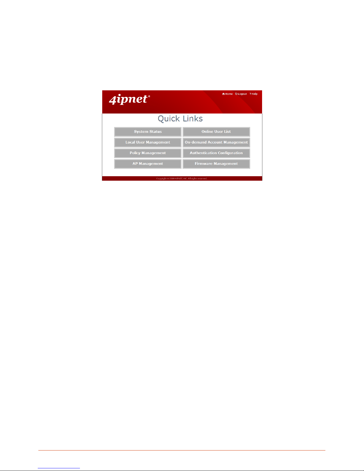
The Quick Links provide eight shortcut links for administrator s to directly access frequently used functions of the
web management interface. The eight functional links are: System Status, Local User Management, Policy
Management, AP Management, Online User List, On-demand Account Management, Authentication
Configuration and Firmware Management.
Page 34
34
4.2.3. System Overview
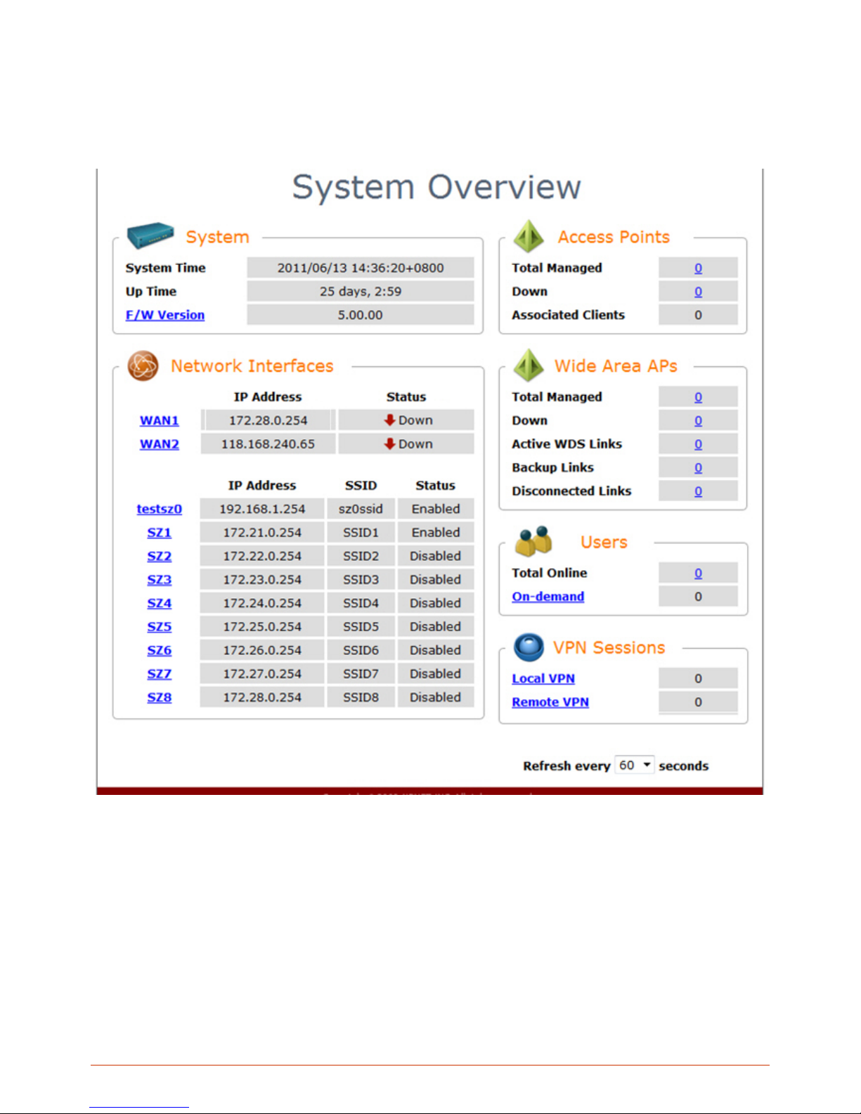
This page displays important system related information that the administrator might need to be aware of at a glance,
which includes General System settings, Network Interface and Online Users etc. A drop-down menu is available for
selecting the information refresh rate for this page.
Page 35
35
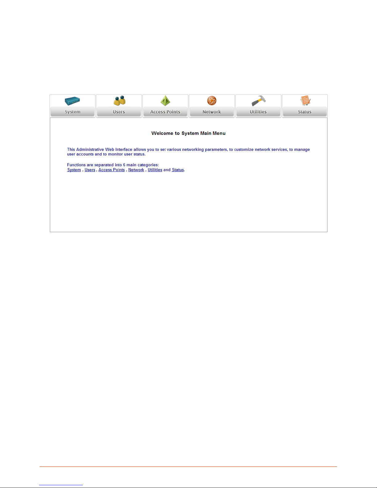
4.2.4. Main Menu
This feature leads to all the detailed configuration pages on the Web Management Interface, allowing you to set
various networking parameters, enable and customize network services, manage user accounts and monitor user
status. Administration functions are separated into 6 categories: System, Users, Access Po int s, Network,
Utilities and Status.
Page 36

36
4.2.5. Online Help
The Help button is at the upper right corner of the WHG Controller display screen.
Click Help for the O nline Help window, and then click the hyperlink of the relevant information required.
Online Help Corner
Page 37
37
5. Initial Network Setup
5.1. Network Requirement
Typically, in a network environment, WHG Controller plays the role of a gateway. On a gateway device, a network
port leading upstream to the Internet or the backbone network is called a ‘WAN port’ or an uplink port, wh ile a
network port used for branching out to the service the clients downstream is referred as ‘LAN port’.
WHG Controller consists of two WAN ports, which are normally linked up to different routers or modems leading to
ISP. A gateway needs one WAN port only, but if you want dual-homing or dual -uplink to add reliability and
throughput, the second WAN port lets you achieve that goal.
5.2. Managing System Date & Time
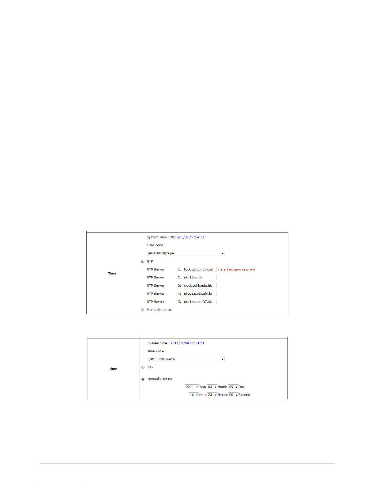
Go to Main Menu > System > General page. The system time can be configured manually or calibrated
automatically through external NTP Servers. Accurate system time is critical when it comes to billing and online
payment.
Calibrate system time using NTP servers, fill in at least one valid NTP server address and apply.
Manually set system time and apply.
Page 38
38
5.3. WAN1 & WAN2 Setup
WHG Controllers are designed with 2 WAN ports for load balancing and failover support. To configure WAN port
settings, go to Main Menu > System > WAN1 / WAN2.
WAN1
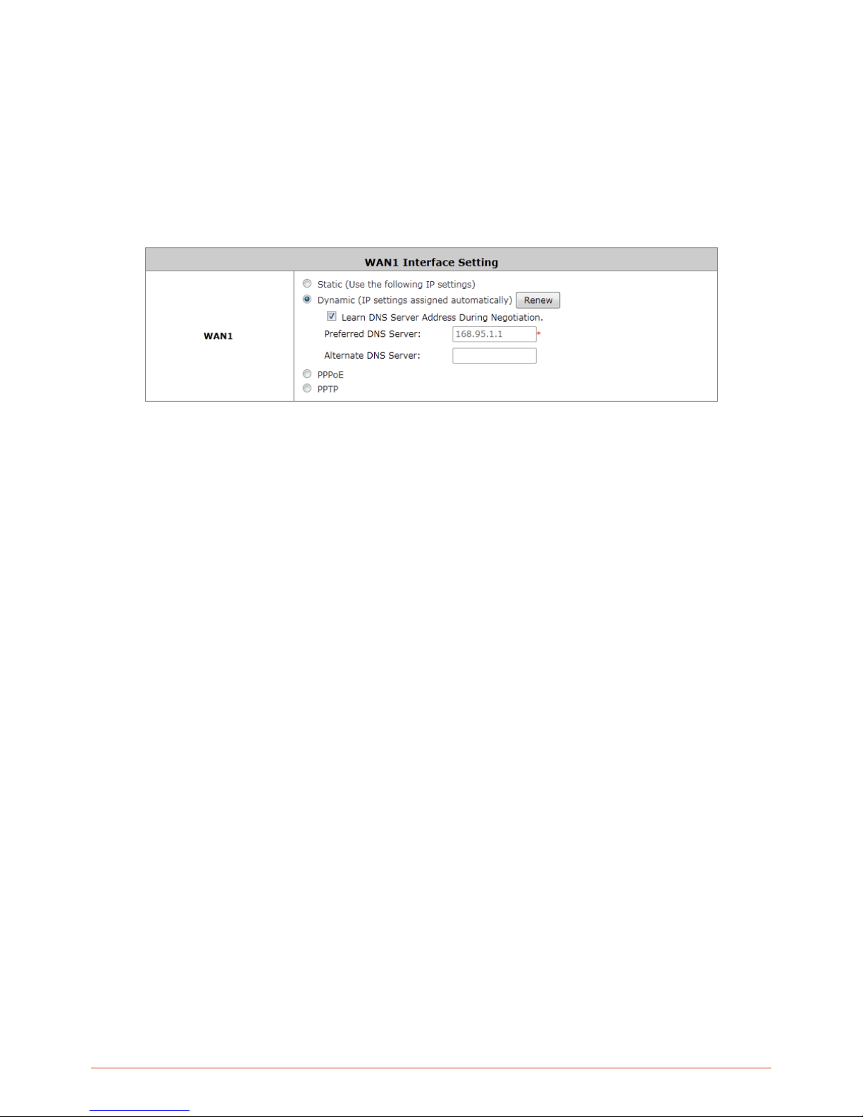
WAN1 port supports four connection types: Static, Dynamic, PPPoE and PPTP. These connection types are
enough to support most ISP.
Depending on ISP or the upstream device the WAN port connects, you only need to select one connection type for
the port. For example, if your ISP is Cable modem issuing Dynamic address, then you would select Dynamic
connection when setting up the WAN ports.
Static: Manually specifying the IP address of the WAN Port. The fields with red asterisks are required to be filled in.
IP Address: The IP address of the WAN1 port.
Subnet Mask: The subnet mask of the WAN1 port.
Default Gateway: The gateway of the WAN1 port.
Preferred DNS Server: Statically designate the primary DNS server to be used by the system.
Alternate DNS Server: The substitute DNS server used by the system. This is an optional field.
Dynamic: It is only applicable for the network environment where the DHCP server is available on the upstream
network. Click the Renew button to get an IP address automatically.
Learn DNS Server Address During Negotiation: When this check box is selected, the Controller will
automatically learn the IP address of DNS server through DHCP messages received.
Preferred DNS Server: Statically designate the primary DNS server to be used by the system.
Alternate DNS Server: The substitute DNS server used by the system. This is an optional field.
PPPoE: If your ISP provides PPP oE Dialup connection, then the ISP will issue you an account with a password. Y ou
would need to enter the account credential in the WAN configuration page for dialing up to the ISP.
Username: The username issued by your ISP as dial-up account.
Password: The dial-up password issued by your ISP.
MTU: Maximum Transmission Unit of a PPPoE frame. The PPPoE protocol allows an Ethernet frame’s
size to be up to 1492 bytes, but some ISP’s network equipments may support a smaller frame size of than
Page 39
39
1492 bytes. In that case, you have to enter a smaller number MTU number to meet the ISP’s networking
requirement.
Clamp MSS: Short for Maximum Segment Size for a TCP connection. An end-to-end TCP connection
over PPPoE will consume additional overhead out of each packet. At least 40 bytes are used for the
address. Hence, MSS must be smaller than MTU by at least 40.
Dial on demand function under PPPoE. If this function is enabled, a Maximum Idle Time will be
available for input a value. When the idle time is reached, the system will automatically disconnect itself.
Learn DNS Server Address During Negotiation: When this check box is selected, the Controller will
automatically learn the IP address of DNS server through DHCP messages received.
Preferred DNS Server: Statically designate the primary DNS server to be used by the system.
Alternate DNS Server: The substitute DNS server used by the system. This is an optional field.
PPTP: Although not a popular method, PPTP protocol for dialup connections is adapted by some ISPs (in European
Countries). Your PPTP ISP will issue you an account with a password as well as the PPTP server address.
Type: Select Static or DHCP. Select Static to specify the IP address of the PPTP Client manually or select
DHCP to get the IP address automatically.
PPTP Server IP Address: Specify your ISP’s PPTP server IP address.
Username: The username issued by your ISP as dial-up account.
Password: The dial-up password issued by your ISP.
PPTP Connection ID:
Dial on demand function under PPTP: If this function is enabled, a Maximum Idle Time will be available for
input a value. When the idle time is reached, the system will automatically disconnect itself.
WAN2
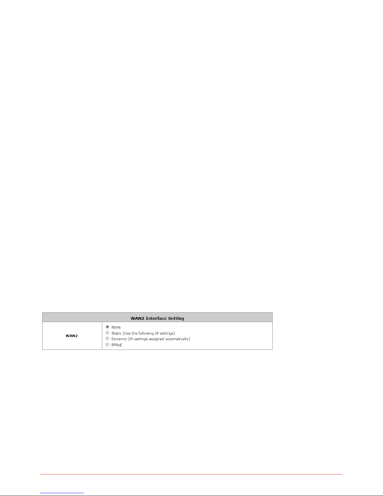
If you want to use a second Internet feed, select one of the three connection types for your WAN2 port: Static,
Dynamic, and PPPoE. Please note that WAN load balancing and WAN failover features are only available when
WAN2 is configured.
Static: Manually specifying the IP address of the WAN Port. The fields with red asterisks are required to be filled in.
IP Address: The IP address of the WAN1 port.
Subnet Mask: The subnet mask of the WAN1 port.
Default Gateway: The gateway of the WAN1 port.
Preferred DNS Server: Statically designate the primary DNS server to be used by the system.
Alternate DNS Server: The substitute DNS server used by the system. This is an optional field.
Dynamic: It is only applicable for the network environment where the DHCP server is available on the upstream
network. Click the Renew button to get an IP address automatically.
Page 40
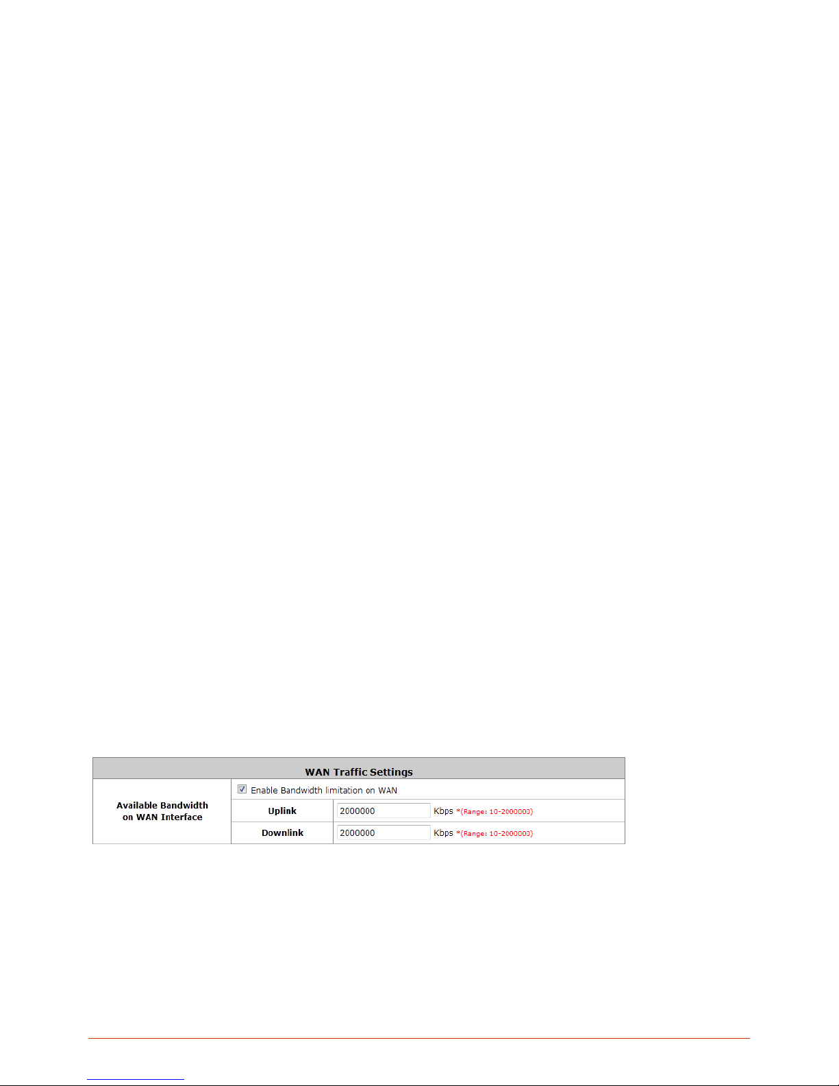
40
Learn DNS Server Address During Negotiation: When this check box is selected, the Controller will
automatically learn the IP address of DNS server through DHCP messages received.
Preferred DNS Server: Statically designate the primary DNS server to be used by the system.
Alternate DNS Server: The substitute DNS server used by the system. This is an optional field.
PPPoE: If your ISP provides P PPoE Dialup connection, then the ISP will issue you an account with a password. You
would need to enter the account credential in the WAN configuration page for dialing up to the ISP.
Username: The username issued by your ISP as dial-up account.
Password: The dial-up password issued by your ISP.
MTU: Maximum Transmission Unit of a PPPoE frame. The PPPoE protocol allows an Ethernet frame’s
size to be up to 1492 bytes, but some ISP’s network equipments may support a smaller frame size of than
1492 bytes. In that case, you have to enter a smaller number MTU number to meet the ISP’s networking
requirement.
Clamp MSS: Short for Maximum Segment Size for a TCP connection. An end-to-end TCP connection
over PPPoE will consume additional overhead out of each packet. At least 40 bytes are used for the
address. Hence, MSS must be smaller than MTU by at least 40.
Dial on demand function under PPPoE. If this function is enabled, a Maximum Idle Time will be
available for input a value. When the idle time is reached, the system will automatically disconnect itself.
Learn DNS Server Address During Negotiation: When this check box is selected, the Controller will
automatically learn the IP address of DNS server through DHCP messages received.
Preferred DNS Server: Statically designate the primary DNS server to be used by the system.
Alternate DNS Server: The substitute DNS server used by the system. This is an optional field.
5.4. WAN Traffic Control
WAN Bandwidth
The entire system’s uplink and downlink bandwidth can be customized. Go to Main Menu > System > WAN Traffic
The Uplink and Downlink bandwidth configured here is the combined bandwidth for WAN1 and WAN2. However,
please note that the actual bandwidth is still bounded by the network speed of your ISP operator. For instance the
network speed of your ISP is limited to 1Gbps, then the total throughput will not be greater than 1Gbps even if you
configure 2Gbps on the Controller.
WAN Failover & Load Balancing
Page 41
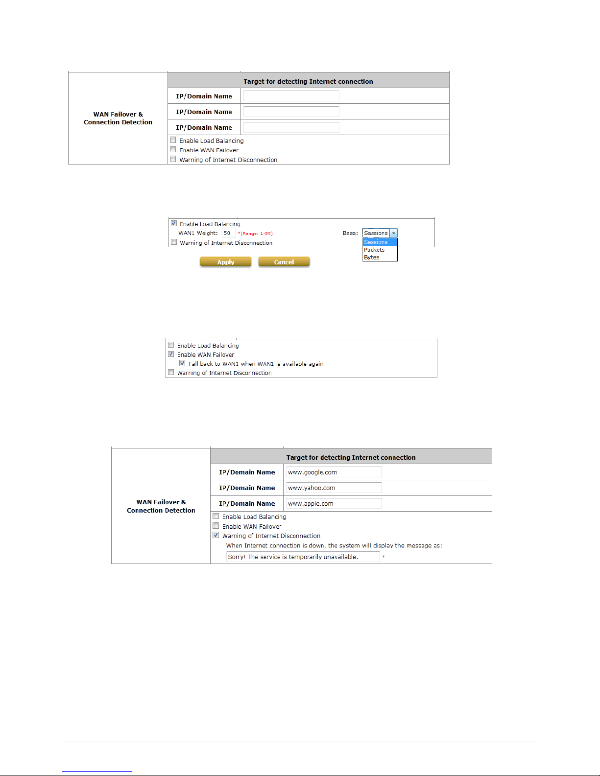
41
When both WAN1 and WAN2 are properly configured with uplink to the internet, WAN failover and Load Balancing
feature becomes available.
Load Balancing: Administrator can spread the system traffic across WAN1 and WAN2 ports based on percentage
load, calculated using session, bytes, or packets.
WAN Failover: Once enabled, whenever WAN1 is down, WAN2 will service the traffics originally handled by WAN1
until WAN1 link is up again and vice versa. This feature is not available to be used concurrently with Load
Balancing.
WAN Connection Detection
The system will periodically check to see if the Internet (uplink) connection is down by seeing if it can get responses
from three target sites.
Warning of Internet Disconnection: When check box is checked, the entered message will be displayed on clients’
web browser when outbound internet connection is down.
5.5. LAN Port & Service Zone Mapping
WHG Controllers support 2 types of VLAN modes, Port-Based and T ag-Based. Go to Main Menu > System > LAN
Port Mapping
Page 42
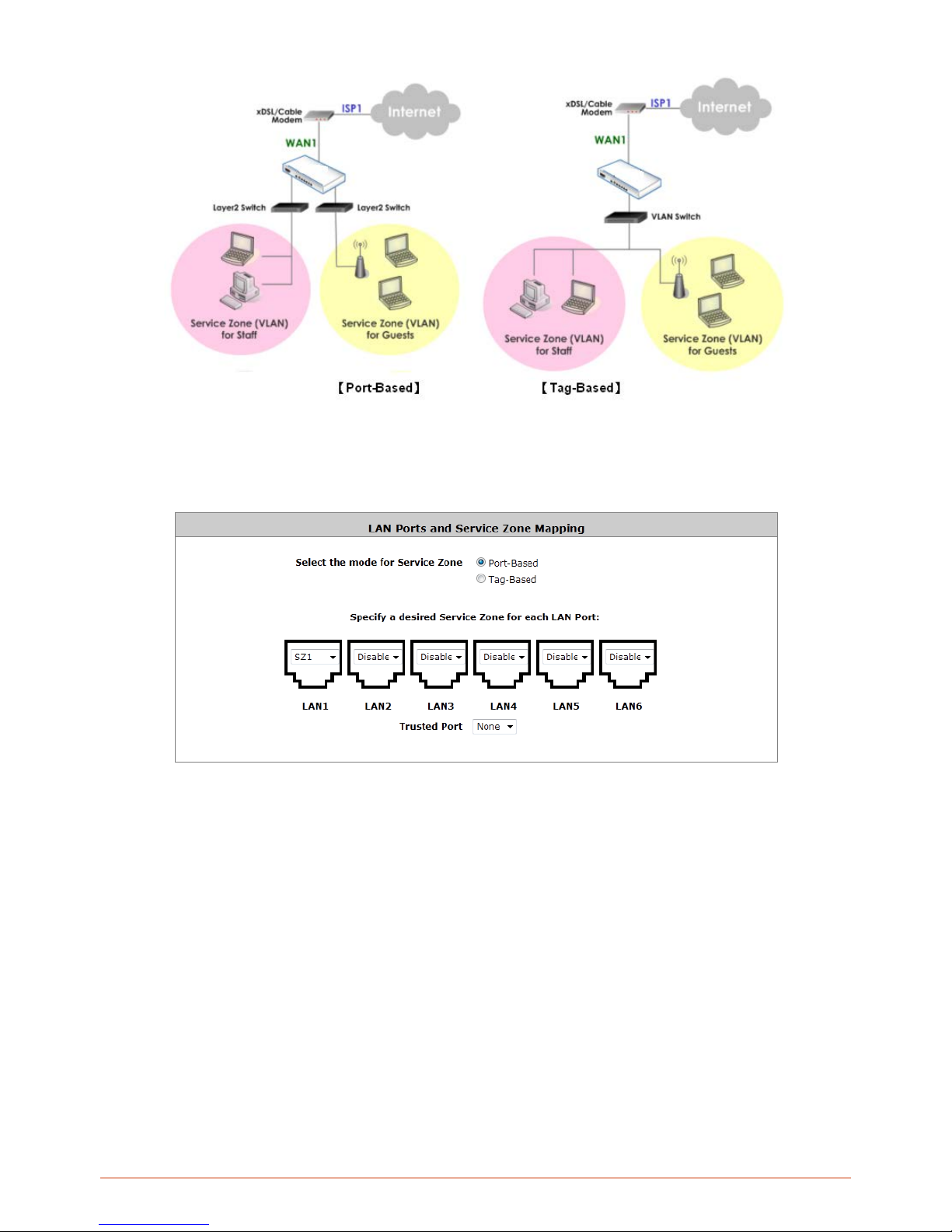
42
In Port-Based mode each LAN port can be mapped to an enabled Service Zone or disabled, this means the
maximum number of Service Zones available to provide service is determined by the number of LAN ports on the
Controller.
Trusted Port: When a LAN port is selected, clients under this port will not require authentication regardless of the
settings in the corresponding Service Zone profile this LAN port maps to.
In T ag-Based mode, Service Zones are mapped to VLAN tags. This means that each LAN port can service any
service zone traffic.
Page 43
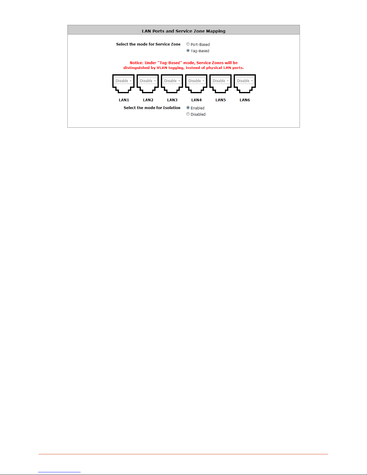
43
Select the mode for Isolation: When enabled, network traffic will be isolated by VLAN tag, which means that
inter-VLAN devices are segregated from each other. Please note that this check option is not available for WHG-311
and WHG-315 and are always enabled.
Page 44
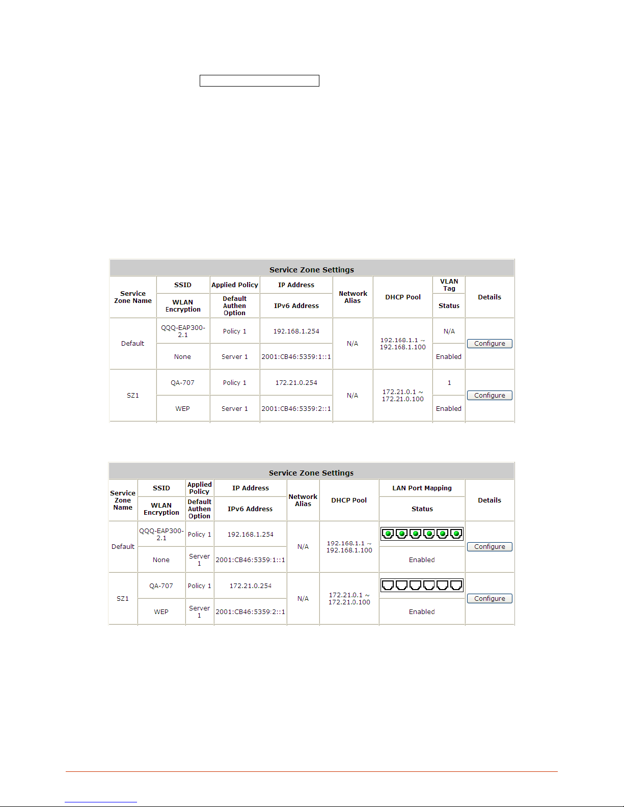
44
5.6. LAN Partition -- Service Zone
Configure Service Zone; go to: System >> Service Zones.
A Service Zone is a logical network area to cover certain wired and wireless networks in an organization such as
SMB or branch offices. By associating a unique VLAN Tag and SSID with a Service Zone, administrators can
separate wired network and wireless network into different logical zones. Users attempting to access the resources
within the Service Zone will be controlled based on the access control profile of the Service Zone, such as
authentication, security feature, wireless encryption method, traffic control, and etc.
There are up to nine Service Zones to be utilized; by default, they are named as: Default, SZ1~SZ8, as shown in the
table below.
Tag-B ased Mode
Port-Based Mode
Service Zo ne N am e : Mnemonic name of the Service Zone. SSID: The SSID that is associated with the Service
Zone.
WLAN Encryption: Data encryption method for wireless networks within the Service Zone.
Applied Policy: The policy that is applied to the Service Zone.
Page 45

45
Default Authen Option: Default authentication method/server that is used within the Service Zone.
IP Address: The IPv4 address of this service zone interface.
IPv6 Address: The IPv6 address of this service zone interface.
Network Alias: Administrator may optionally set many alias network segments for a service zone. This feature
can allow a single service zone to be seen as many service zones, also hide the IP address of a Service Zone’s
network interface and to some degree, provide protection from possible attacks from LAN clients.
DHCP Pool: Displays the DHCP pool range configured for this service zone.
VLAN Tag (Tag Base only): The VLAN tag number that is mapped to the Service Zone.
LAN Port Mapping (Port Base only): The physical port that is mapped to this service zone, indicated by green
light icon.
Status: Each Service Zone can be enabled or disabled.
Details: Configurable, detailed settings for each Service Zone.
Click Configure button to configure each Service Zone: Basic Settings, SIP Interface Configuration,
Authentication Settings, Wireless Settings, and Managed AP (s) in this Service Zone.
Page 46
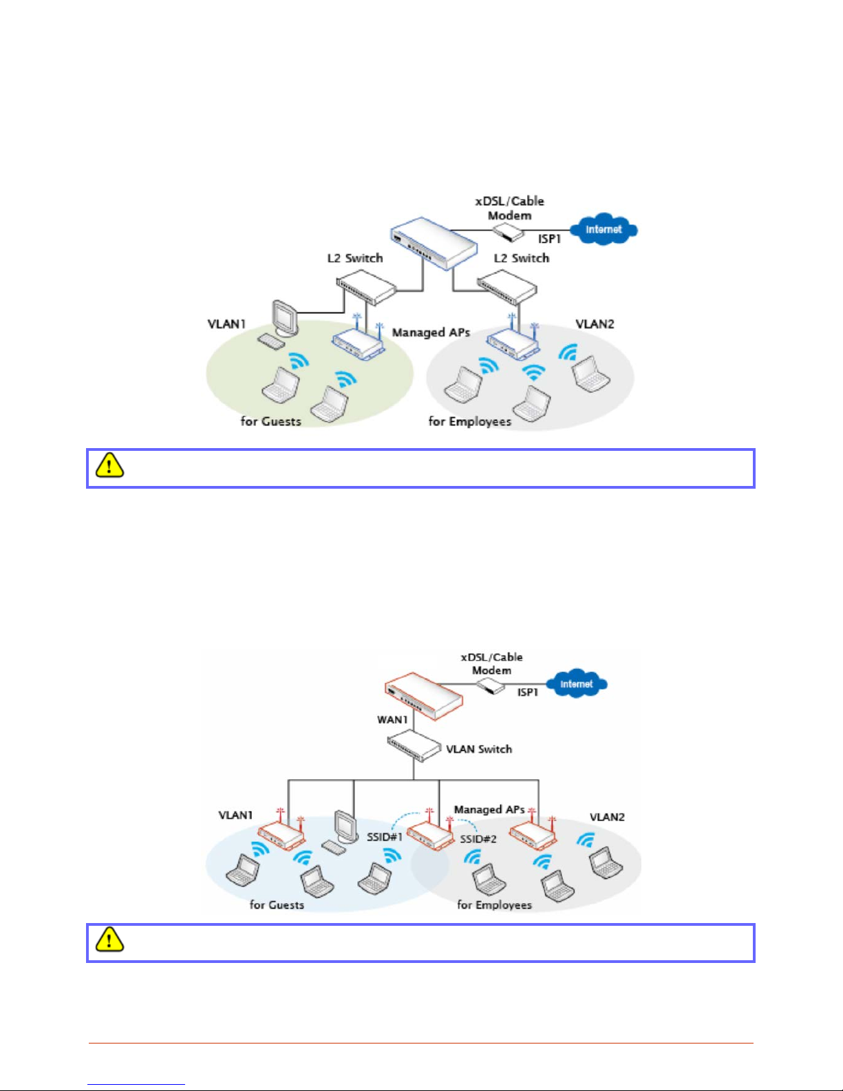
46
5.6.1. Planning Your Internal Network
Simple network environment
For most simple internal network, such as there are just only two subnets. Using Port-Based model is an easy
and better way. In Port-Based mode, each LAN port can only serve traffic from one Service Zone. An example
of network application diagram is shown as below: one Service Zone for Employees and one for Guests.
The switches deployed under WHG Controller in Port-Based mode must be Layer 2 switches only.
Multi subnet network environment
On the other hand, if the internal network is a Multi subnets network enviro nment, Tag-Based model will satisfy to
your conditions. In Tag-Based mode, each LAN port will serve traffics from different Service Zones; a VLAN switch
or VLAN AP is required to take care of the VLAN tags carried within the message frames.
An example of network application diagram is shown as below: more than two Service Zones for different
departments.
The switch deployed under WHG Controller in Tag-Based mode must be a VLAN switch only.
Page 47
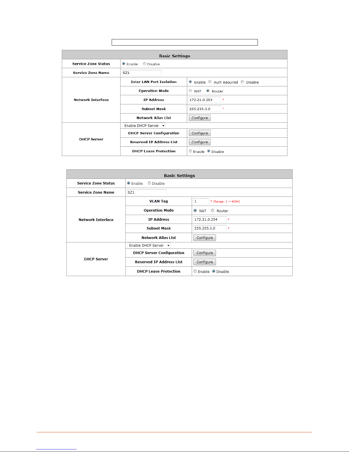
47
5.6.2. Configure Service Zone Network
Configure Service Zone; go to: System >> Service Zones >> Service Zone Configuration.
Router Mode
NAT Mode
Service Zone Status: Each service zone can be enabled or disabled except for the default service zone.
Service Zone Name: The name of service zone could be input here.
Network Interface:
o VLAN Tag (Tag Base Only): The VLAN tag number that is mapped to the Service Zone.
o Inter LAN Port Isolation (Port Base Only): Select Enable, Auth Required or Disable. When the
option is “Enabled”, clients under different LAN ports cannot ping each other. When the option is
“Disabled”, clients under different LAN ports can ping each other. When the option is “Auth
Required”, clients under different LAN ports cannot ping each other unless both of them has
successfully authenticated.
o Operation Mode: Contains NAT mode and Router mode. When NAT mode is chosen, service zone
runs in NAT mode. When Router mode is chosen this service zone runs in Router mode.
o IP Address: The IP Address of this service zone.
o Subnet Mask: The subnet Mask of this service zone.
Page 48
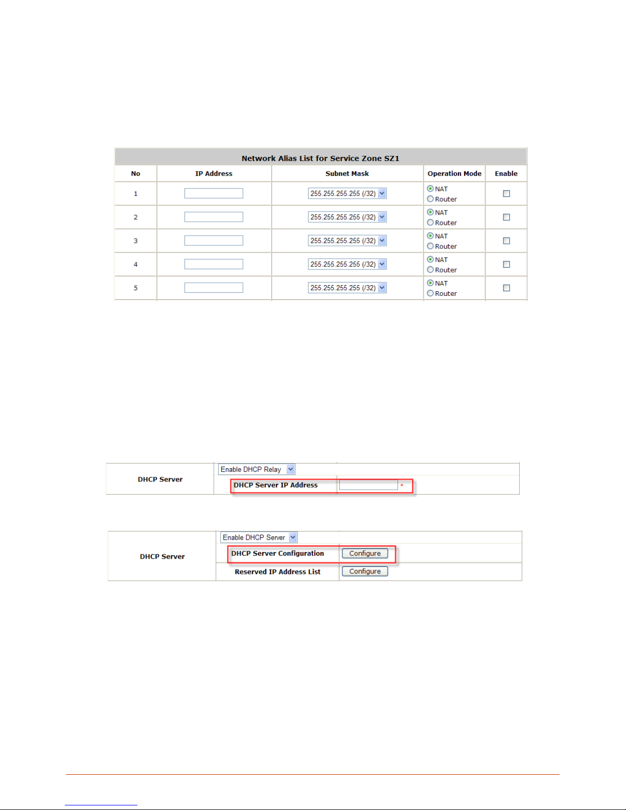
48
o IPv6 Settings: The IPv6 Address and configuration of this service zone (When IPv6 enabled).
o Network Alias List: Administrator may optionally set many alias network segments for a service
zone. This feature can allow a single service zone to be seen as many service zones, also hide the
IP address of a Service Zone’s network interface and to some degree, provide protection from
possible attacks from LAN clients.
Click the Configure button to enter the Network Alias List page.
Fill in the desired alias IP address and select the preferred Subnet Mask, Operation mode,
check the Enable box and click Apply button to activate the settings.
DHCP Server: From the drop down menu, DHCP server for this particular service zone may be Disabled,
Enabled or Relayed.
Please note that when “Enable DHCP Relay” is enabled, fill in the IP address of the external DHCP Server,
and the IP address of clients will be assigned by an external DHCP server. The system will only relay
DHCP information from the external DHCP server to downstream clients of this service zone. Pleas e not e
that Controller should be in the same subnet as the DHCP server.
When Enable DHCP Server option is selected, click Configure button to enter settings page.
Page 49
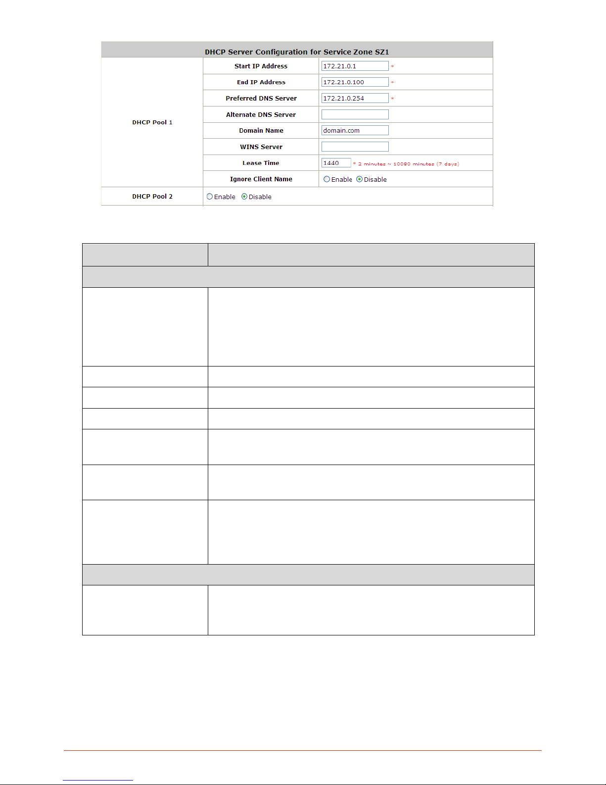
49
Item Description
DHCP Server 1
Start IP Address / End IP
Address
A range of IP addresses that built-in DHCP server will assign to clients. Note: please
change the Management IP Address List accordingly (at System Configuration >>
System Information >> Management IP Address List) to permit the administrator to
access the WHG CONTROLLER admin page after the default IP address of the
network interface is changed.
Preferred DNS Server
The primary DNS server that is used by this Service Zone.
Alternate DNS Server
The substitute DNS server that is used by this Service Zone.
Domain Name
Enter the domain name for this service zone.
WINS Server
The IP address of the WINS (Windows Internet Naming Service) server that if WINS
server is applicable to this service zone.
Lease Time
This is the time period that the IP addresses issued from the DHCP server are valid
and available.
Ignore Client Name
When enabled the system will not record the name of the device requesti ng for an IP
address. On the other hand, when disabled is selected, the system will record the
device’s name when issuing IP addresses. The devices name (Host Name) can be
seen under DHCP Lease tab.
DHCP Server 2
Enable/Disable
When Enabled, an additional DHCP server can be configured to assign IP address to
clients associated to the alias IP of this Service Zone. The configurable fields are the
same as DHCP Server 1.
Reserved IP Address List: Each service zone can reserve specific IP addresses from predefined DHCP
range to prevent the system from issuing these IP addresses to downstream clients. Click the Configure
button to edit the Reserved IP List.
Page 50
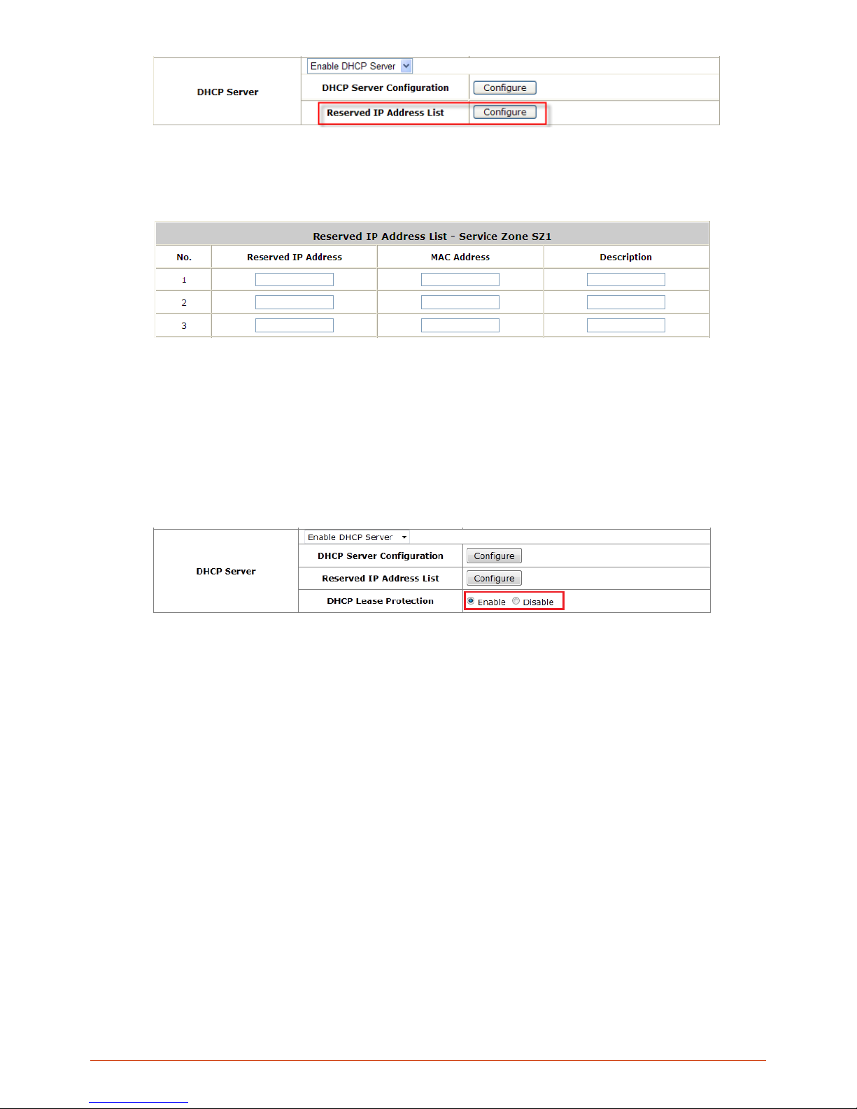
50
The administrator can reserve a list of specific IP addresses for special device with certain MAC address.
Fill a set of IP address and MAC address as reserve, additional information can be entered in the
Description field. Click Apply to activate your settings.
DHCP Lease Protection: When “Enabled”, whenever the Service Zone’s built-in DHCP server receives a
DHCP request, it will automatically bind the MAC address with an IP address permanently. This means
that once all the IP address has been assigned once, it will be bound with the MAC address that first
acquired this IP, subsequent devices with new MAC address will be unable to acquire an IP address.
When “Disabled” DHCP server will operate as usual, assigning available IP addresses upon DHCP
request.
Page 51
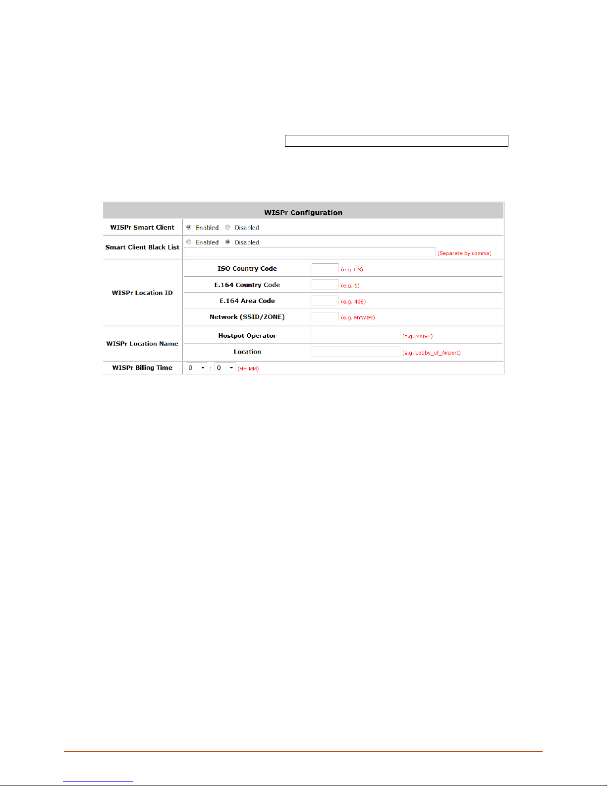
51
5.6.3. WI S P r Attributes in Service Zone
WISPr or Wireless Internet Service Provider roaming - Pronounced "whisper," WISPr is a draft protocol submitted to
the Wi-Fi Alliance that allows users to roam between wireless internet service providers, in a fashion similar to that
used to allow cell phone users to roam between carriers. A RADIUS server is used to authenticate the subscriber's
credentials.
To configure WISPr attributes in Service Zone, go to: System >> Service Zones >> WISPr Configuration.
If a RADIUS server has been configured, the WISPr attributes used during RADIUS authentication can be defined
here in this Service Zone.
WISPr Smart Client: Select Enable if you wish to allow customers with a roaming account from a WISPr
agent (iPass, WiFi Skype, Boingo, and etc.) to access your internet. Make sure to Enable the HTTPS
Protected Login field under System >> General in order for roaming software on the client’s device to
work properly.
Smart Client Black List: Fill in the WISPr agent names and enable to block users from that particular
WISPr roaming agent to access your internet. For example, if you fill in “ipassconnect” the iPass clients
will be denied roaming access in your network.
WISPr Location ID: These attributes, which enable wireless hotspot providers to customize their web
portals, are based on the client device location and are RADIUS vendor-specific attributes (VSAs).
WISPr Location Name: These attributes, which enable wireless hotspot providers to customize their
web portals, are based on the client device location and are RADIUS vendor-specific attributes (VSAs).
WISPr Billing Time: Set RADIUS account billing time.
Page 52
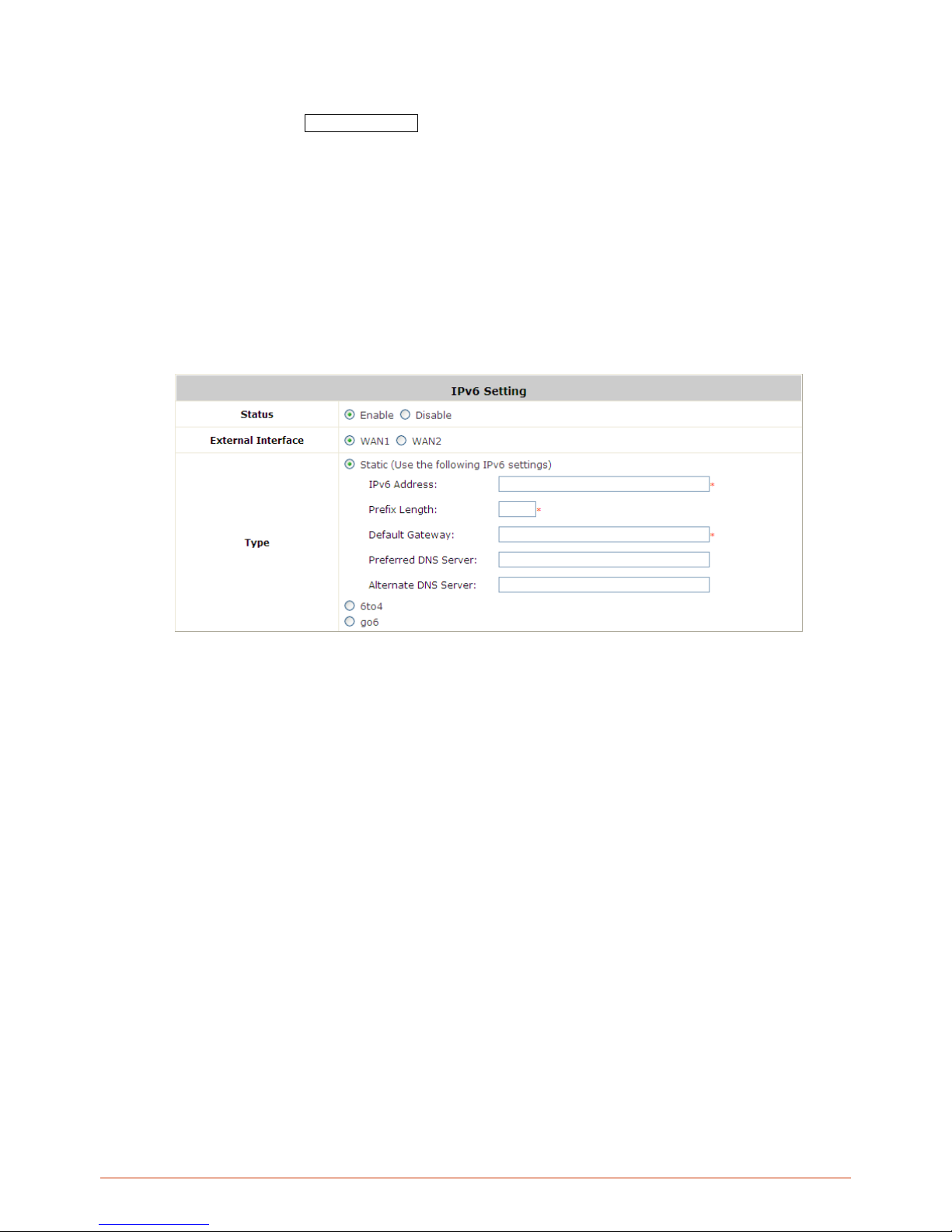
52
5.7. IPv6
Configure Service Zone; go to: System >> IPv6.
System implements IPv6 feature and supports operating in IPv6 networking environment. When IPv6 is enabled,
administrator may assign IPv4 IP address as well as IPv6 address to each interface such as WAN1, WAN2, Default
Service Zone, Service Zone1, etc.
Status: Enable or Disable the use of IPv6 addressing standard.
External Interface: Select the external interface of the device that will be configured with an IPv6 address.
Type: Choose the desired way of your IPv6 connection.
Static: Manually enter all the related IPv6 information. Red asterisk are mandatory fields.
IPv6 Address: Enter the desired IPv6 IP address.
Prefix Length: Set the desired length of your IPv6 mask.
Default Gateway: The IPv6 default gateway of the selected interface.
Preferred DNS Server: The primary DNS server used for this connection.
Alternate DNS Server: The substitute DNS server used for this connection.
Page 53
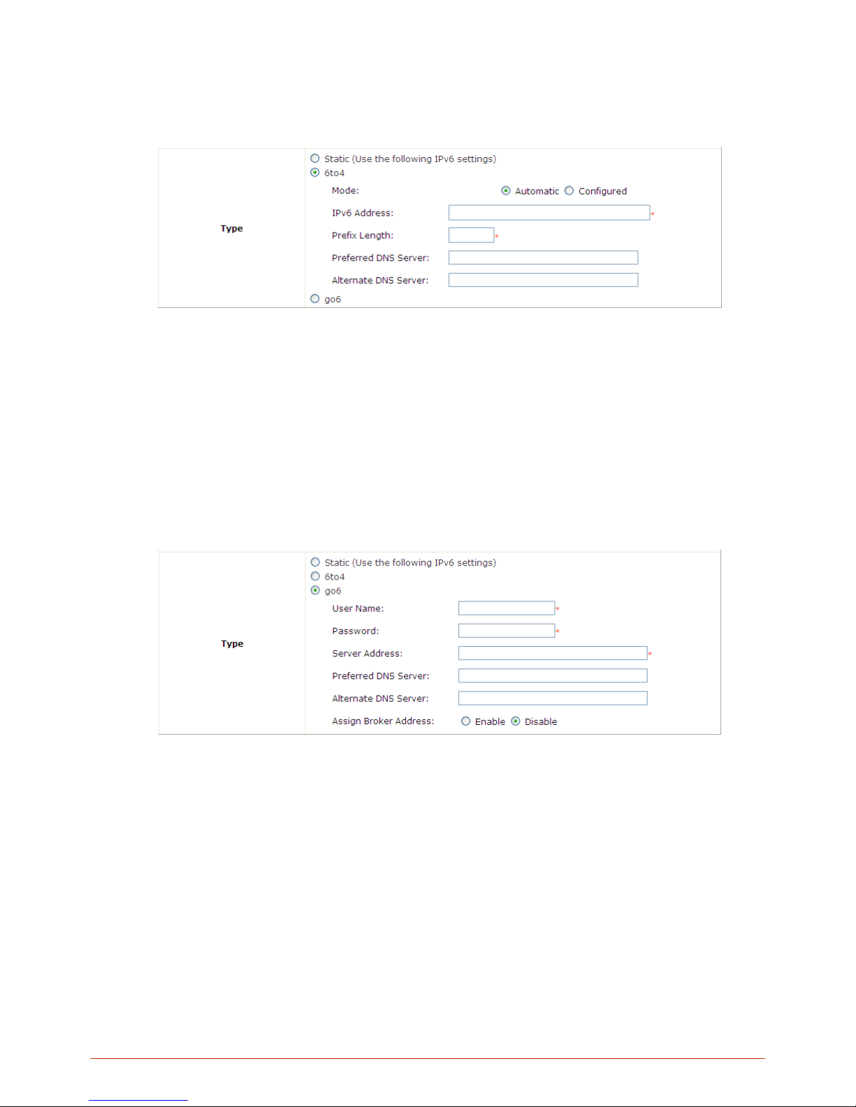
53
6to4: 6to 4 is an Internet transition m echanism for migrating from IPv4 to IPv6, a system that allows IPv6
packets to be transm itted over an IPv4 net work (generally the IPv4 internet) without the need to configure
explicit tunnels. 6to4 option can on ly be c hosen when t he selec ted WAN interface was set with a stat ic IP v4
address.
Mode: Select Automatic if you do not h ave a specified default router, or c hoose Configured to
assign a default router to forward packet from IPv6 network to IPv4 network.
IPv6 Address: Enter the desired IPv6 IP address.
Prefix Length: Set the desired length of your IPv6 mask.
Default Router: The default router that routes packets from IPv6 to IPv4 network.
Preferred DNS Server: The primary DNS server used for this connection.
Alternate DNS Server: The substitute DNS server used for this connection.
go6: go6 is a platform that connects the world to the new Internet with IPv6 products, community and
services. You may choose this connection option if you have a registered account.
Username: Username of your go 6 account.
Password: Password of your go6 account.
Server Address: The servicing go6 server address.
Preferred DNS Server: The primary DNS server used for this connection.
Alternate DNS Server: The substitute DNS server used for this connection.
Assign Broker Address: Select Enable if you wish to use tunnel broker service .
Broker Address: The address of your broker.
Page 54
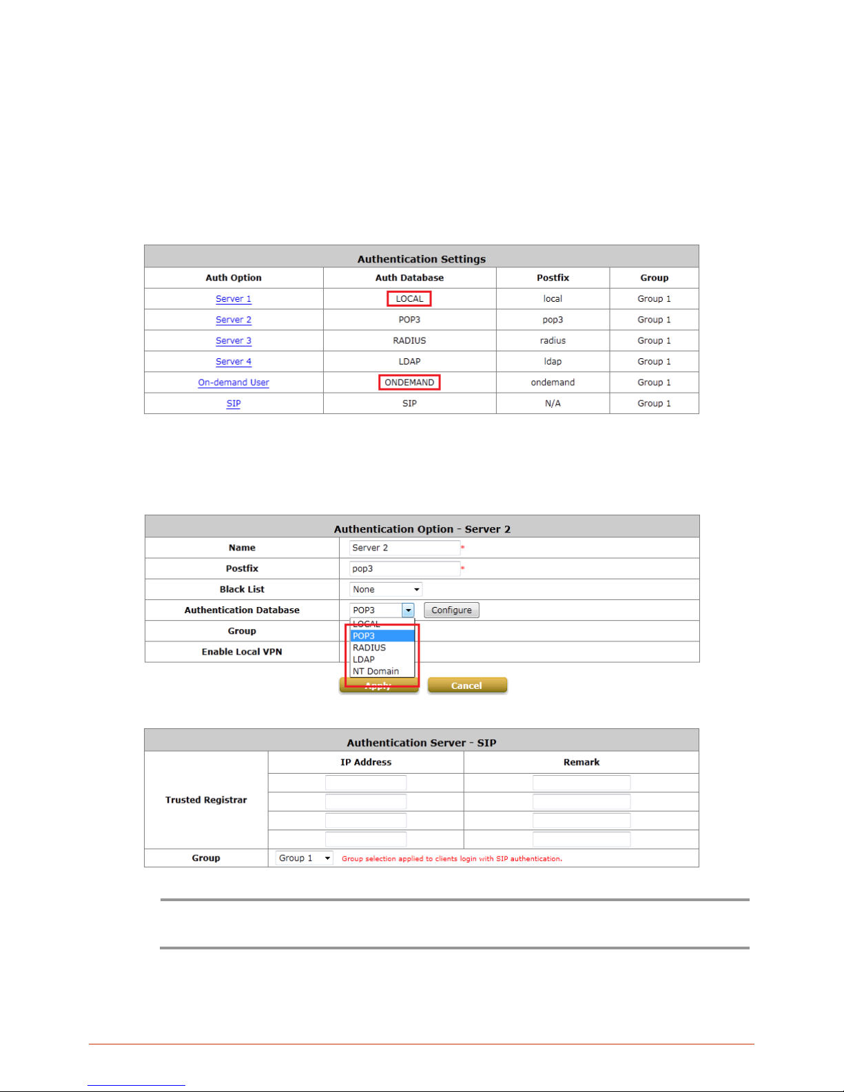
54
6. User Authenti cation and Grouping
6.1. Overview of User Authentication Database
•
Built-in User Databases
Local and On-demand are Controller ’s built-in user databases designed to house static and temporary accounts
respectively. Local database is ideal for storing long term accounts for instance employee accounts while
On-demand database is ideal for generating temporary accounts for guest usage.
•
External User Database
System supports 4 types of external user databases (POP3, RADIUS, LDAP, NT Domain) and 4 SIP (voice/video)
servers.
Note:
Concurrently only one server is allowed to be set as Local or NTDOMAIN authentication method
simultaneously. For example, you can set two RADIUS authentication servers simultaneously.
Authentication Option Configuration
Page 55
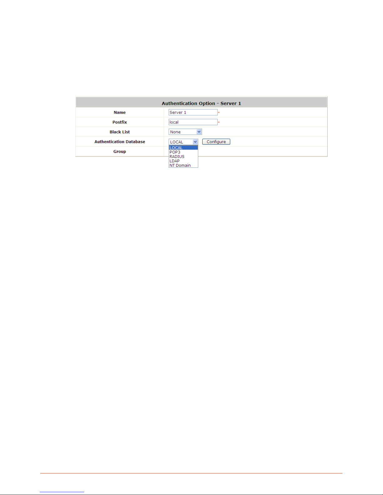
55
Go to Main Menu > Users > Authentication
Click on the server name to set the configuration for that particular server. After completing and clicking Apply to
save the settings. Then go back to System > Service Zones and enable or disable any server in each service
zone as you prefer. For each Service Zone, one of the authentication servers can be set as default, users can
log into the default authentication server without the postfix to allow faster login process.
Server 1~4: There are 5 authentication databases, Local User, POP3, RADIUS, LDAP and NT Domain, to
select from.
Name: Set a name for the authentication option by using numbers (0~9), alphabets (a~z or A ~Z), dash (-),
underline (_), space and dot (.) only. The length of this field is up to 40 characters. This name is used for the
administrator to identify the authentication options easily such as HQ-RADIUS.
Postfix: A postfix is used to inform the s ystem which auth entic ation opt ion to be used f or authe nticat ing an
account (e.g. bob@BostonLdap or tim@TaipeiRadius) when multiple options are concurrently in use. One of
authentication option can be assigned as def aul t. For auth ent ic ati on ass i gne d as def ault, the pos tf ix can b e
omitted. For exam ple, if "BostonLdap" is t he postfix of the default option, Bob can login as "bob" without
having to type in "bob@Bo stonLdap”. Set a postf ix that is easy to disti nguish (e.g. Local) an d the server
numbers (0~9), alphabets (a~z or A~Z), dash (-), underline (_) and dot (.) within a maximum of 40
characters. All other characters are not allowed.
Black List: There are 10 sets of black lists provided by the system. A user account listed in the black list is
not allowed to log into the system, the client's access will be denied. The administrator may select one (or
None) black list from the drop-down menu and this black list will be applied to this specific authentication
option.
Authentication Database: Click Configure button to enter the confi guration page. For example, select
Local from the drop-down list box and then click Configure button to enter the Local User Database
Settings. Then, click the hyperlink of Local User List.
Group: Select one Group from the drop-down list box for this specific authentication option.
Page 56
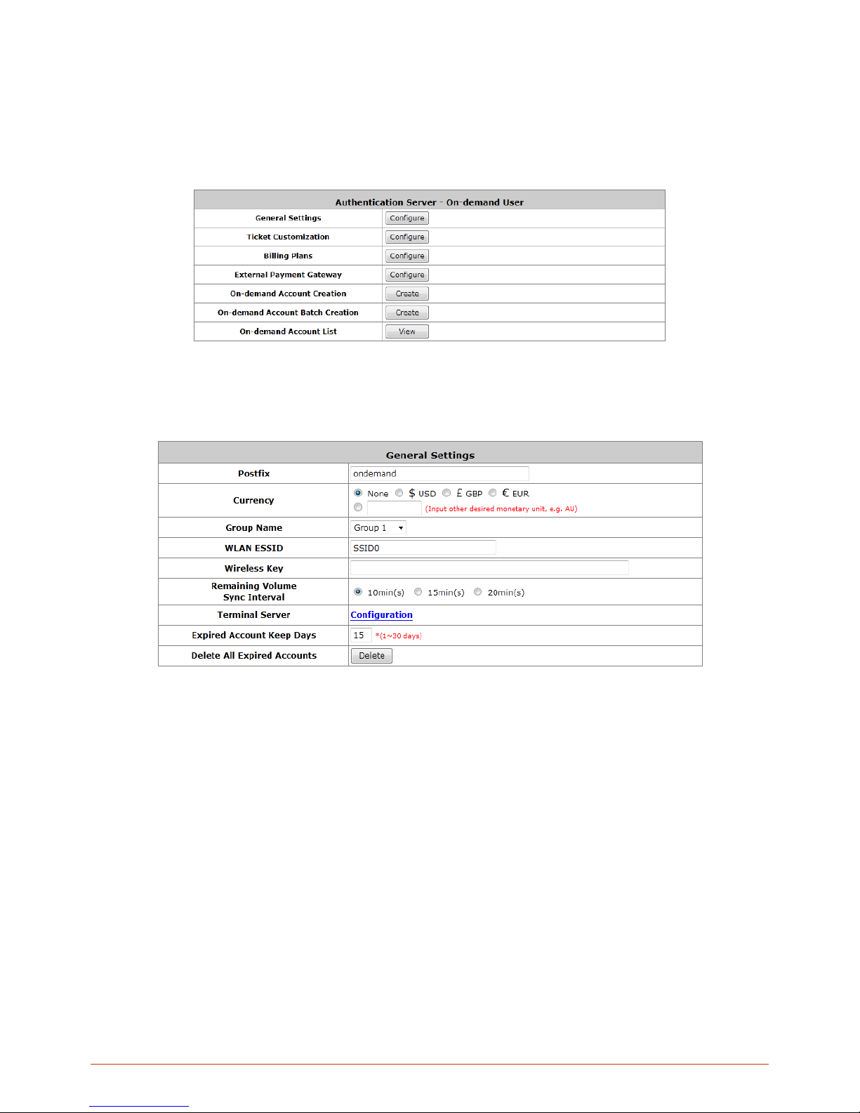
56
6.1.1. Configuring On-demand
The administrator can enable and configure this authentication method to create on-demand user accounts. This
function is designed for hotspot owners to provide temporary users with free or paid wireless Internet access in the
hotspot environment. Major functions include accounts creation, users monitoring list, billing plan and external
payment gateway support.
1) General Settings
This is the common setting for the On-demand User authentication option. The generated on-demand users and
all accounts related information such as postfix and unit will be shown in this list.
Postfix: Postfix is used to inform the system which type of authentication database as account belongs to
for authentication when multiple databases are concurrently in use. Enter the string to be used as postfix for
on-demand users.
Currency: Select the desired monetary unit or specify other unit in the input field.
Group Name: Select the desired group for on-demand user.
WLAN ESSID: The administrator can enter the defined wireless ESSID in this field and it will be printed on
the receipt for on-demand users’ reference when accessing the Internet via wireless LAN service. The
ESSID given here should be ESSID of Service Zones that has enabled On-demand database as an
authentication server.
Wireless Key: The administrator can enter the defined wireless key such as WEP or WPA i n the field. The
Wireless Key will be printed on the receipt for the on-demand users’ reference when accessing the Internet
via wireless LAN service.
Remaining Volume Sync Interval: While the on-demand user is still logged in, the system will update the
billing notice of the login successful page by the time interval defined here.
Terminal Server: Terminal Configuration is a list of serial-to-Ethernet devices that communicate with the
Page 57
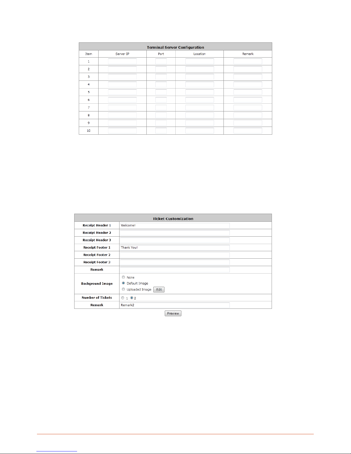
57
system only; never get online and no need to go through authentication. NetTicketGen is an example of
terminal server that is required to be configured here before it can operate with Controller.
Expired Account Keep Days: When an Ondemand account expires, it will remain on the ondemand
account list for a certain amount of time. The number of days to retain an expired ondemand account can be
specified here.
Delete All Expired Accounts: A click of the “Delete” button will delete all expired accounts on the
Ondemand account list and recycle these accounts ready for new account generation.
2) Ticket Customization
On-demand account ticket can be customized here and previewed on the screen.
↓
Page 58
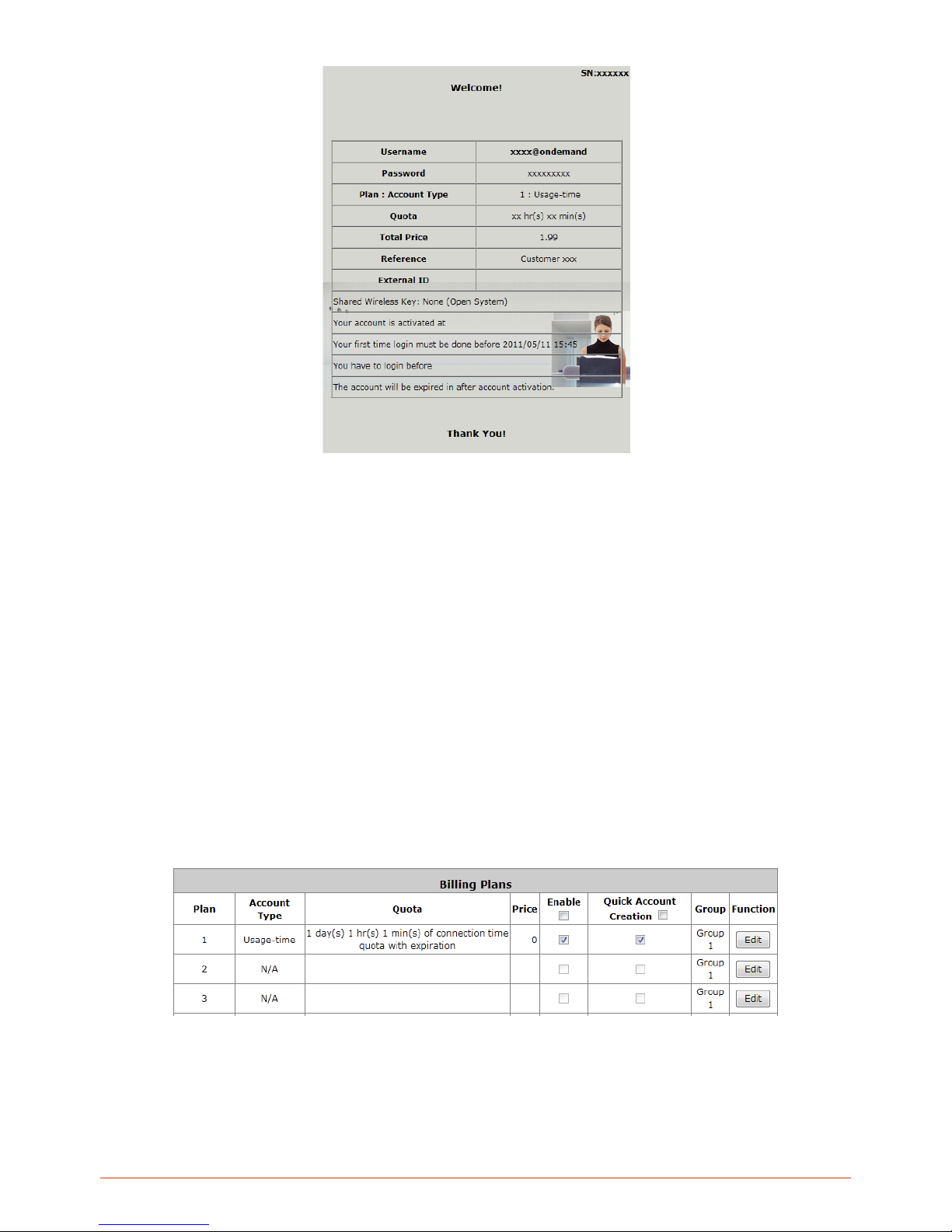
58
Receipt Header: There are 3 receipt headers supported by the system. The entered content will be printed
on the receipt. These headers are optional.
Receipt Footer: The entered content will be printed on the receipt. This footer is optional.
Background Image: You can choose to customize the ticket by uploading your own background image for
the ticket, or choose the default image or none. Click Browse to select the image file and then click upload.
The background image file size limit is 100 Kbytes. No limit for the dimensions of the image is set, but a
460x480 image is recommended.
Twin Ticket: Enable this function to print duplicate receipts.
Remark: Enter any additio nal inf ormation that will appear at the bottom of the receipt.
Preview: Click Preview button, the ticket will be shown including the information of username and
password with the selected background. Print the ticket here.
3) Billing Plans
Billing plan profiles defines the terms and condit ions of guest internet acces s. Click Edit bu tton to enter the
configuration page of a s elec ted B illi ng Plan pr of il e. Onc e you ha ve f in ished c o nf igurin g a b il ling p lan profile, go
back to the screen of Billing Plans, check the Enable checkbox and click Apply to activate.
Plan: The number of the specific plan.
Account Type: The account type chosen for this plan. Different account types have different properties. A
suitable account type should be selected that will best meet guest usage requirements.
Quota: The usage terms on how much or how long an On-demand users are allowed to access the
Page 59
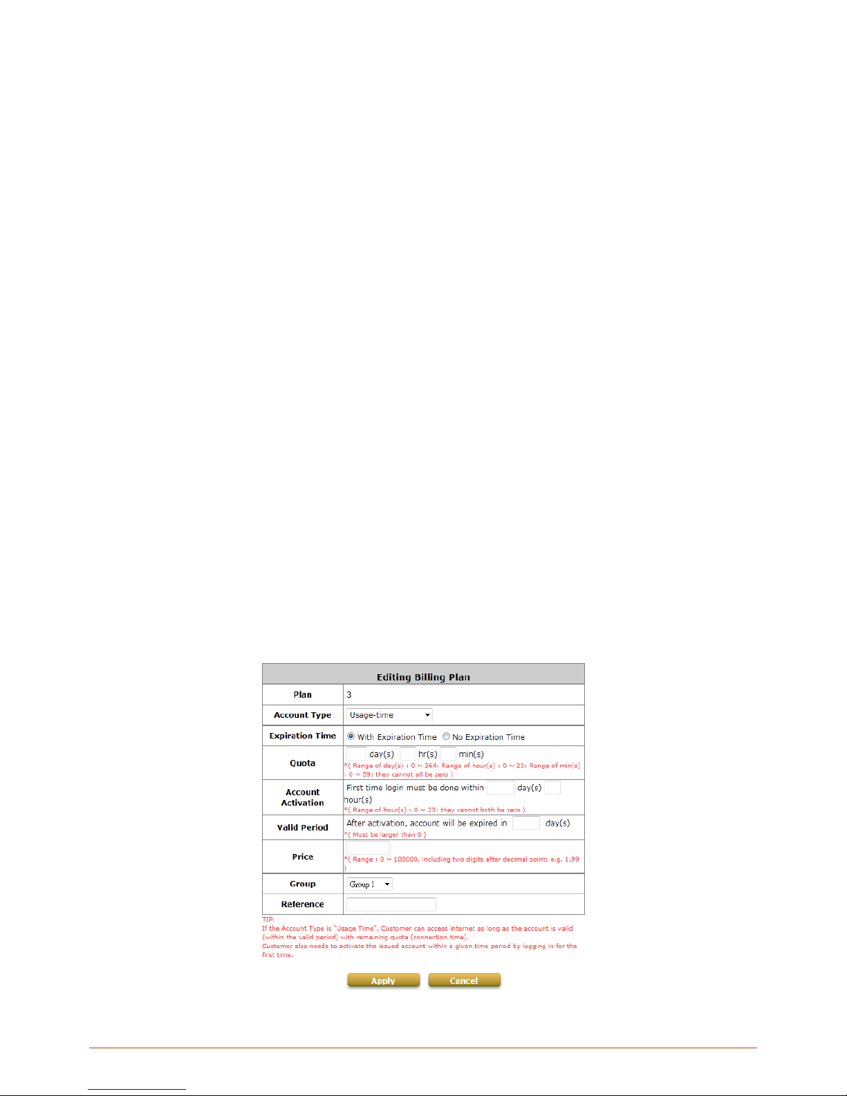
59
network.
Price: The unit price of the respective billing plan.
Enable: Check the checkbox to activate the plan. Deactivated billing plans cannot be used to generate
ondemand guest accounts.
Quick Account Creation: Check the checkbox to enable Quick Account Creation. Static users with
“Ondemand Account Privilege” (an attribute in Group profile) enabled can see “Quick Account Creation”
checked billing plans and can generate ondemand accounts.
Group: Group assignment of on-demand users associated with the respective billing plan.
Function: Click the button Edit to configure the respective billing plan profile.
4) Ondemand Account Types
o Usage-time with Expiration Time: Can access internet as long as account valid with remaining quota
(usable time). Need to activate the purchased account within a given time period by logging in for the first
time. Ideal for short term usage. For example in coffee shops, airport terminals etc. Only deducts quota
while using, however the count down to Expiration Time is continuous regardless of logging in or out.
Account expires when Valid Period has been used up or quota depleted.
Quota is the total period of time (xx days yy hrs zz mins), during which On-demand users are
allowed to access the network. The total maximum quota is “364Days 23hrs 59mins 59secs” even
after redeeming.
Account Activation is the time period for which the user must execute a first login. Failure to do so
in the time period set in Account Activation, the account will expire.
Valid Period is the valid time period for using. After this time period, even with remaining quota the
account will still expire.
Price is the unit price of this plan.
Group will be the applied Group to users created from this plan.
Reference field allo ws adm inistr at or to input add iti on al inf ormation.
Page 60
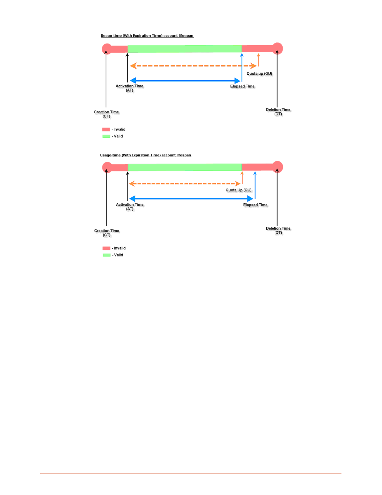
60
o Usage-time with No Expiration Time: Can access internet as long as account h as rem aining quot a
(usable time). Need to activate the purchased account within a given time period by logging in for the
first time. Ideal for short term usage. For example in coffee shops, airport terminals etc. Only deducts
quota while using. Account expires only when quota depleted.
Quota is the total period of time (xx days yy hrs zz mins), during which On-demand users are
allowed to access the network. The total maximum quota is “364Days 23hrs 59mins 59secs”
even after redeem.
Account Activation is the time period for which the user must execute a first login. Failure to
do so in the time period set in Account Activation, the account will expire.
Price is the unit price of this plan.
Group will be the applied Group to users created from this plan.
Reference field allo ws adm inistr at or to input add iti on al inf ormation.
Page 61
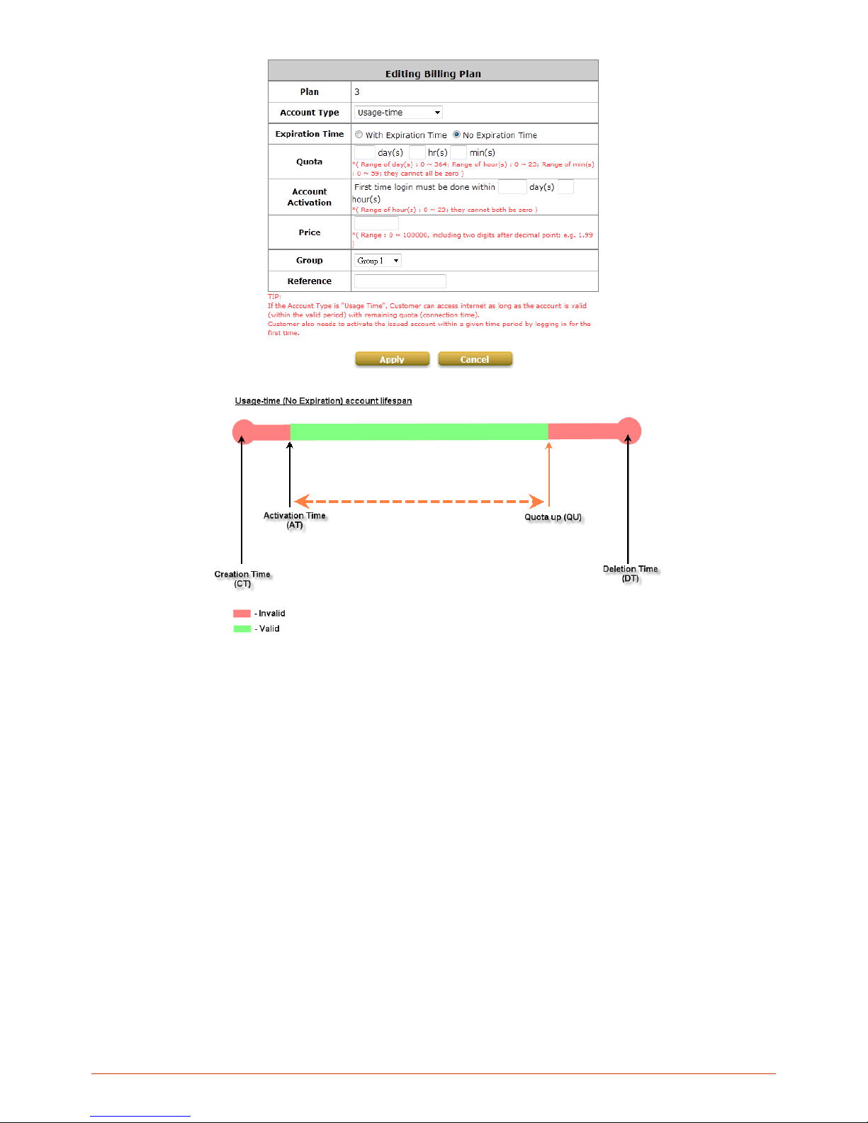
61
Page 62
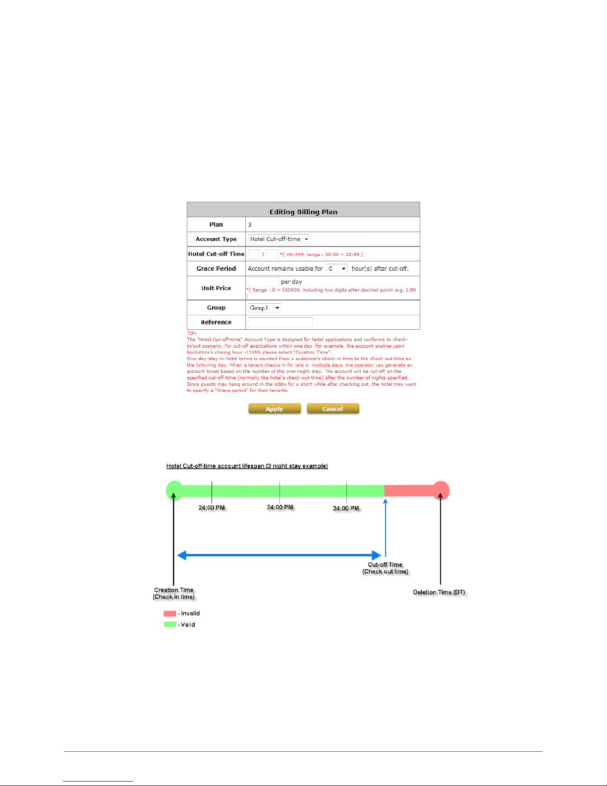
62
Hotel Cut-off-time: Hotel Cut-off-time is the clock time (normally check-out time) at which the
on-demand account is cut off (made expired) by the system on the following day or many days
later. On the account creation UI of this plan, operator can enter a Unit value which is the
number of days to Cut-off-time according to customer stay time. For example: Unit = 2 days,
Cut-off Time = 13:00 then account will expire on 13:00 two days later. Grace Period is an
additional, short period of time after the account is cut off that allows user to continue to use the
on-demand account to access the Internet without paying additional fee. Unit Price is a daily
price of this billing plan. Mainly used in hostel venues to provide internet service according to
guests’ stay time. Group will be the applied Group to users created from this plan. Reference
field allows administrator to input additional information.
Page 63
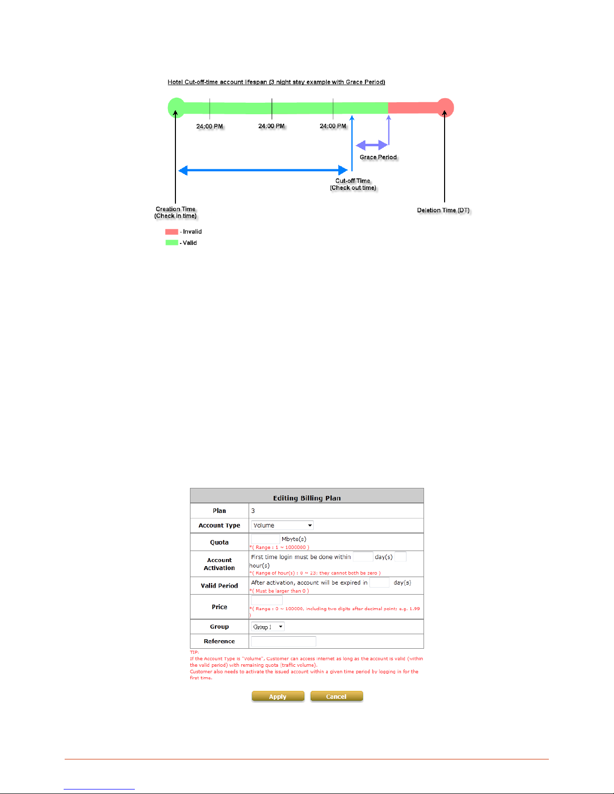
63
o Volume: Can access internet as long as account valid with remaining quota (traffic volume). Account
expires when Valid Period has been used up or quota depleted. Ideal for small quantity applications
such as sending/receiving mail, transferring a file etc. Count down of Valid Period is continuous
regardless of logging in or out.
Quota is the total Mbytes (1~1000000), during which On-demand users are allowed to access
the network.
Account Activation is the time period for which the user must execute a first login. Failure to
do so in the time period set in Account Activation, the account will expire.
Valid Period is the valid time period for using. After this time period, even with remaining quota
the account will still expire.
Price is the unit price of this plan.
Group will be the applied Group to users created from this plan.
Reference field allo ws adm inistr at or to input add iti on al inf ormation.
Page 64
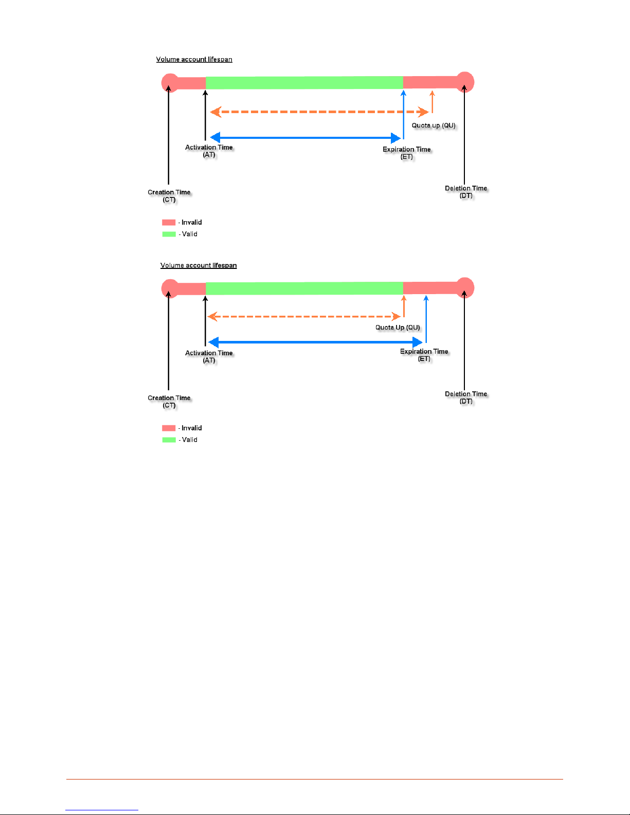
64
o Duration-time with Elapsed Time: Account activated upon the account creation time. Count down
begins immediately after account created and is continuous regardless of logging in or out. Account
expires once the Elapsed Time has been reached. Ideal for providing internet service immediately
after account creation throughout a specific period of time.
Begin Time is the time that the account will be activated for use. It is set to account creation
time.
Elapsed Time is the time interval for which the account is valid for internet access (xx hrs yy
mins).
Price is the unit price of this plan.
Group will be the applied Group to users created from this plan.
Reference field allo ws adm inistr at or to input add iti on al inf ormation.
Page 65
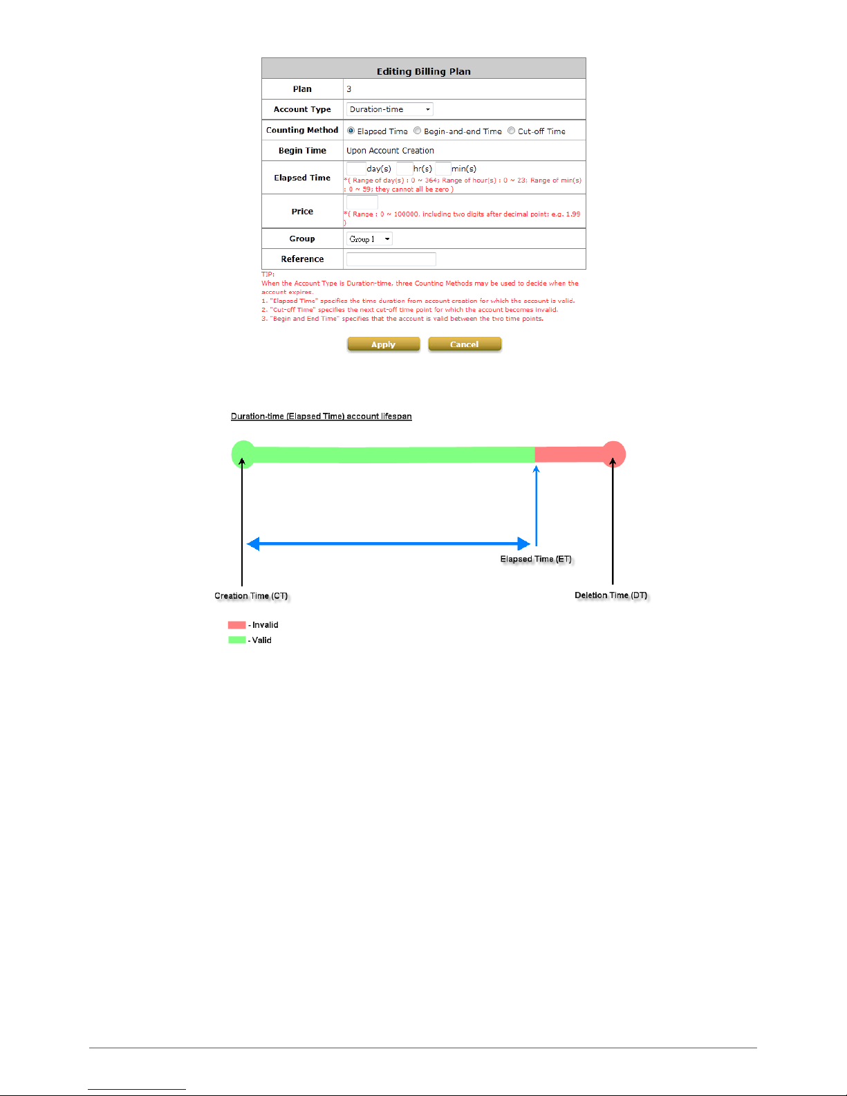
65
o Duration-time with Cut-off Time: Cut-off Time is the clock time at which the on-demand account is
cut off (made expired) by the system on that day. For example a shopping mall closing hour is 23:00;
operators selling on-demand tickets can create use this plan to create ticket set to be Cut-off on 23:00.
If an account of this kind is created after the Cut-off Time, the account will automatically expire.
Begin Time is the time that the account will be activated for use. It is set to account creation
time.
Cut-off Time is the clock time when the account will expire.
Price is the unit price of this plan.
Group will be the applied Group to users created from this plan.
Reference field allo ws adm inistr at or to input add iti on al inf ormation.
Page 66
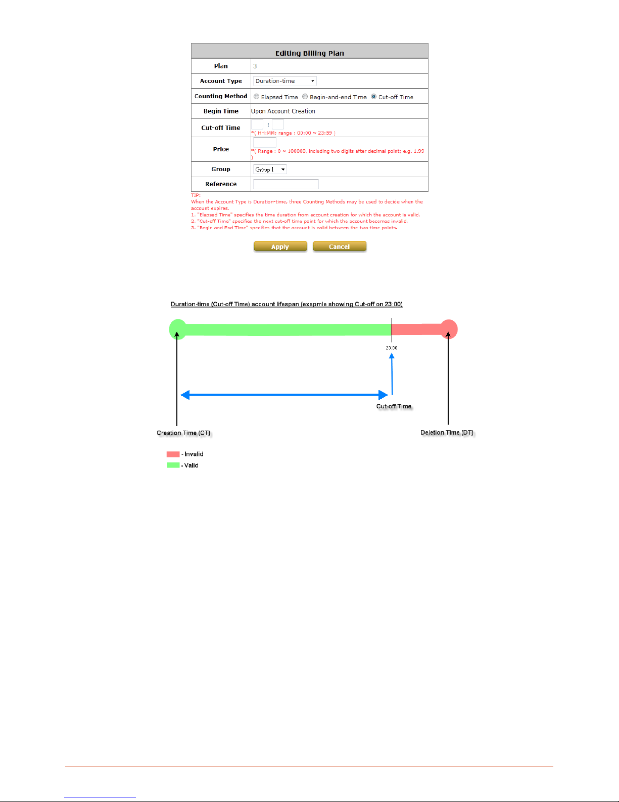
66
o Duration-time with Begin-and End Time: Define explicitly the Begin Time and End Time of the
account. Count down begins immediately after account activation and expires when the End Time has
been reached. Ideal for providing internet service throughout a specific period of time. For example
during exhibition events or large conventions such as Computex where each registered participant will
get an internet account valid from 8:00 AM Jun 1 to 5:00 PM Jun 5 created in batch like coupons.
Begin Time is the time that the account will be activated for use, defined explicitly by the
operator.
End Time is the time that the account will become expired and not able to use any more,
defined explicitly by the operator.
Price is the unit price of this plan.
Group will be the applied Group to users created from this plan.
Reference field allows administrator to input additional infor mation.
Page 67
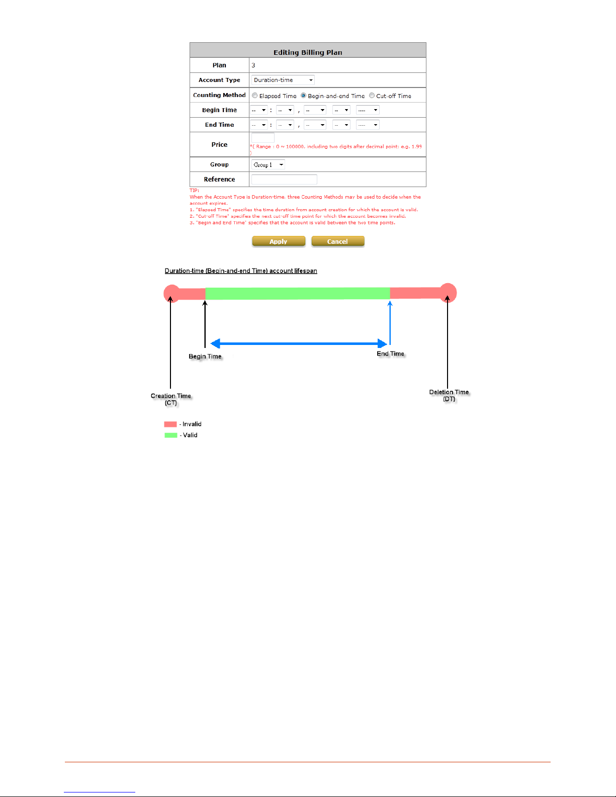
67
Page 68
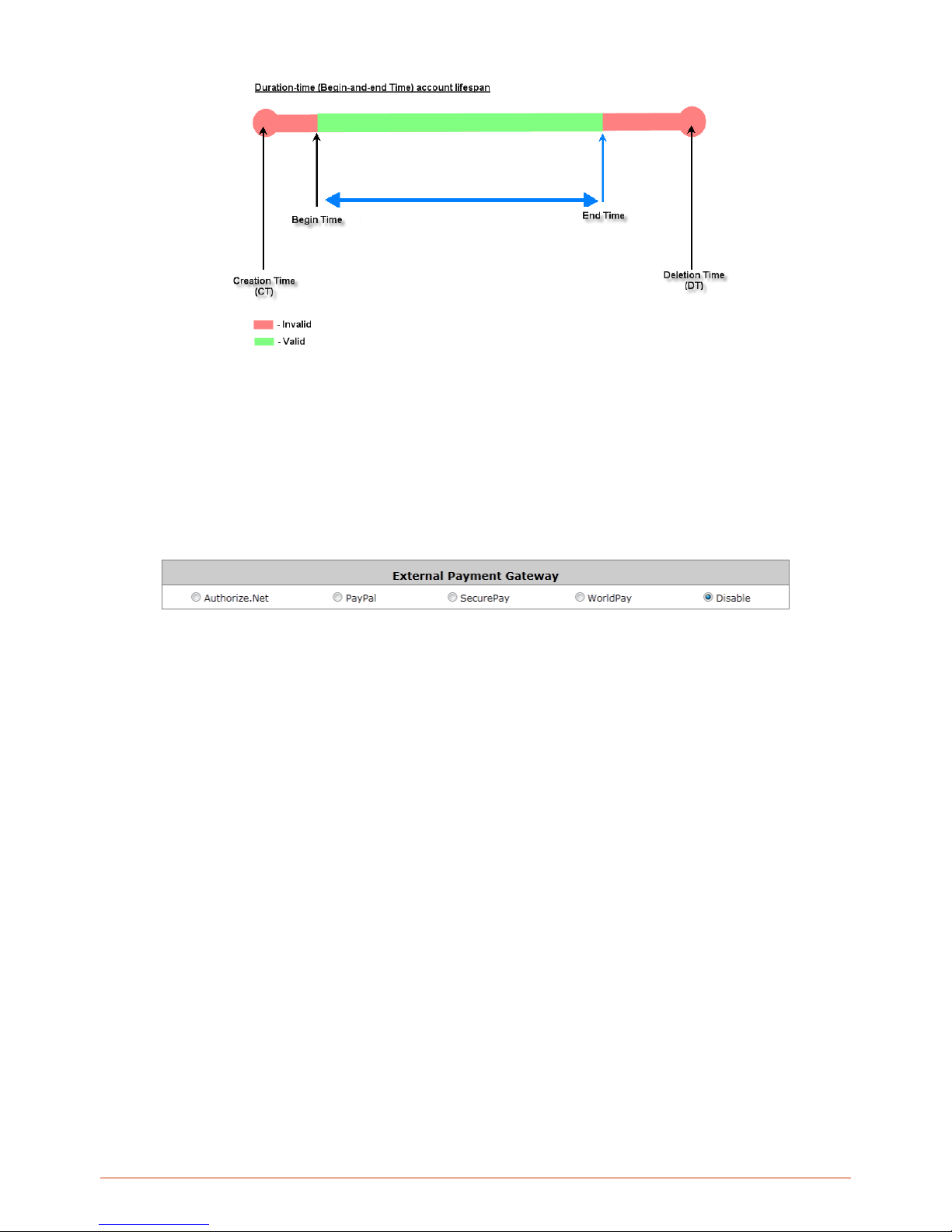
68
5) External Payment Gateway
This section is for merchants to set up an external payment gateway to accept payments in order to provide
wireless access service to end customers who wish to pay for the service on-line.
The four options are Authorize.Net, PayPal, SecurePay, WorldPay and Disable.
Page 69
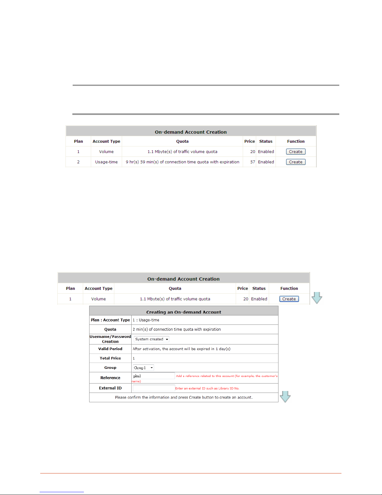
69
6) On-demand Account Creation
After at least one plan is enabled, the administrator can generate on-demand user accounts here. Click on the
Create button of the desired plan and an on-demand user account will be created.
After the account is created, you can print the ticket with all of the necessary on-demand user’s information,
including the username and password.
Note:
If no Billing plan is enabled, accounts cannot be created by clicking Create button. Please goes back to Billing
Plans to active at least one Billing plan by clicking Edit button and Apply the setting to activate the plan. The
printer used by Print is a pre-configured printer connected to the administrator’s computer.
Plan: The number of the specific plan.
Account Type: The account type chosen for this plan. Different account types have different properties. A
suitable account type should be selected that will best meet guest usage requirements.
Quota: The usage terms on how much or how long an On-demand users are allowed to access the
network.
Price: The unit price of the respective billing plan.
Status: Show whether the billing plan is enabled or dis able d.
Function: Press Create button for the desired plan; an On-demand user account will be created, and then
click Printout to print a receipt which will contain this on-demand user’s information.
Page 70
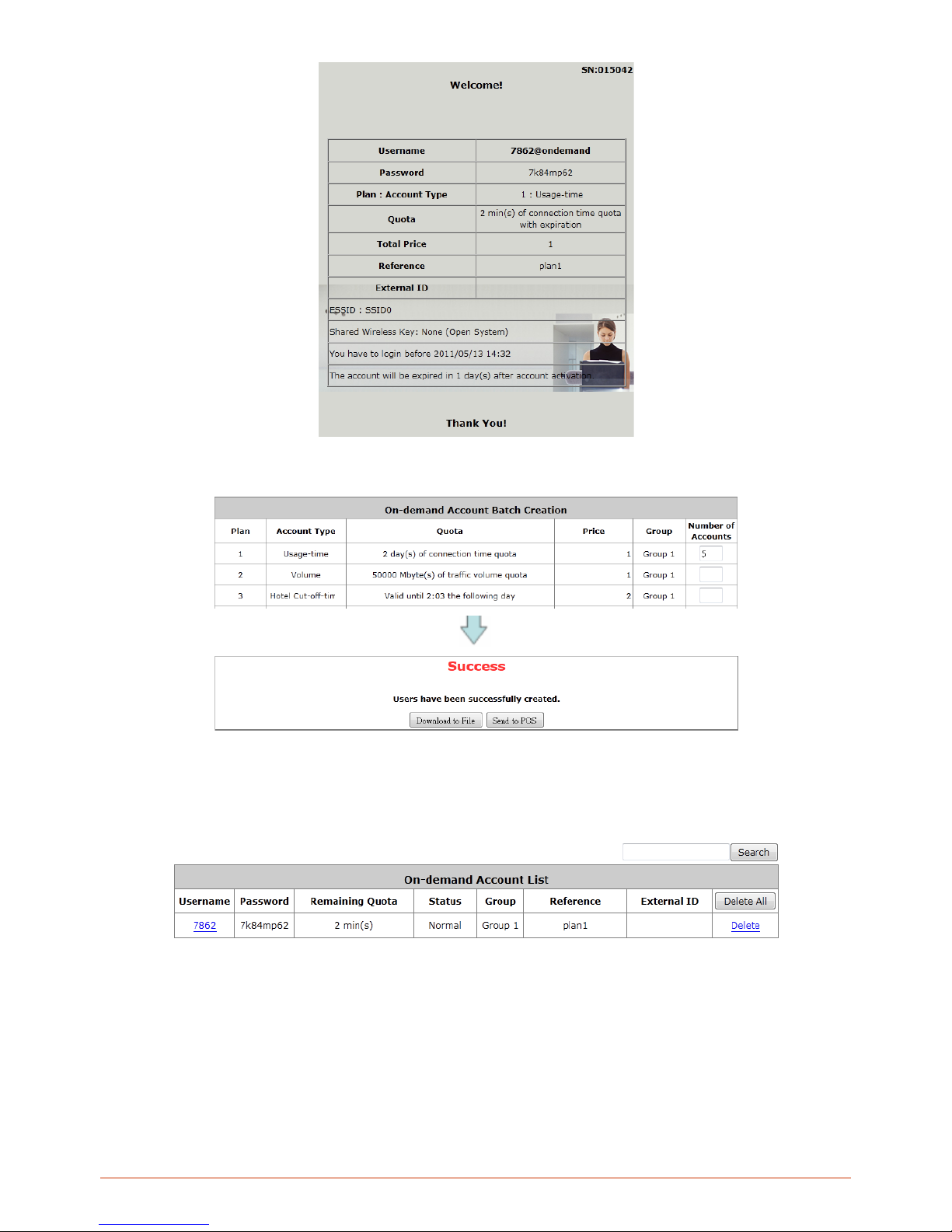
70
Network operator can also choose to create ondemand accounts in batch. Simply specify the number of account to
be generated and click “Create” at the bottom of the page.
The created accounts can be exported as a txt file or printed via pre-configures POS printer
7) On-demand Account List
All created On-demand accounts are listed and related information is also provided.
Search: Enter a keyword of a username, or reference, to be searched in the text filed and click this button to
perform the search. All usernames, or reference, matching the keyword will be listed.
Username: The login name of the account .
Password: The login password of the account.
Remaining Quota: The remaining time or volume, or the cut-off time until this account expires.
Status: The status of the account.
o Normal: the account is not currently in use and also does not exceed the quota limit.
Page 71

71
o Online: the acc ount is curr ently in use.
o Expired: the account is not valid any more, even there is remaining quota to be used.
o Out of Quota: the account has exceeded the quota limit.
o Redeemed: the account has been applied for account renewal.
Delete All: This will delete all ondemand accounts at once.
Delete: This will delete the users individually.
Page 72
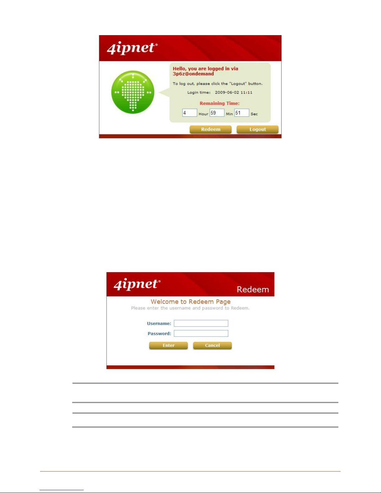
72
Redeem On-demand Accounts
For Time and Volume accounts, if they are almost out of quota, they can use redeem function to extend their quota.
After the user has get, or buy, a new account, they just need to click the Redeem button in the login success page,
input the new account Name and Password and then click Enter. This new account’s quota will be extended to the
original account.
But Redeem function can only redeem to same type of account, Time account must redeem with Time account;
Volume account must redeem with Volume account only.
When the remaining quota is insufficient, the user can add up the quota by purchasing an additional account. Please
enter the new username and password in the Redeem Page and click Enter button to merge the two accounts so
that there will be more quota for the original account.
Note:
The maximum session time/data transfer is 24305 days/9,999,999 Mbytes. If the redeem amount exceeds this
number, the system will automatically reject the redeem process.
Note:
Hotel Cut-off and Duration Time accounts do not support redeem function.
Page 73
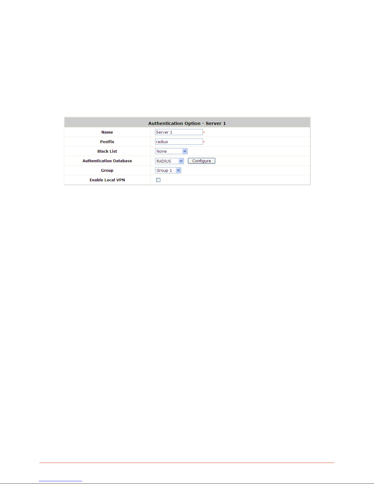
73
6.1.2. Configuring RADIUS
Remote Authentication Dial In User Service (RADIUS) is a networking protocol that provides centralized
Authentication, Authorization, and Accounting (AAA) management for computers to connect and use a network
service.
Choose “RADIUS” from the Authentication Databa se field. The Local VPN option can be enabled or disabled for
the entire Authentication Database.
Name: Configurable text string designated as the mnemonic name of this authentication option.
Postfix: Is the text string entered as a postfix in the account field for notifying the Controller which
authentication database this account belongs to.
Black List: System has built-in black-list profiles where specific user accounts can be listed. When selected
and applied here, it tells the Controller that the accounts on the selected black list should be denied
authentication.
Group: The Group profile that will govern the users authenticated via this authentication option.
Enable Local VPN: When checked, users authenticating with this authentication option will have a VPN
tunnel established automatically between the Controller and the user’s client device.
Authentication Database: Select the authentication database that will be used for account validation when
an authentication request is received. Click the button of Configure for further configuration. The RADIUS
server sets the external authentication server that houses user accounts. Enter the information for the
primary server and/or the secondary server (the secondary server is not required). The fields with red
asterisk are necessary information. These settings will become effective immediately after clicking the
Apply button.
Page 74
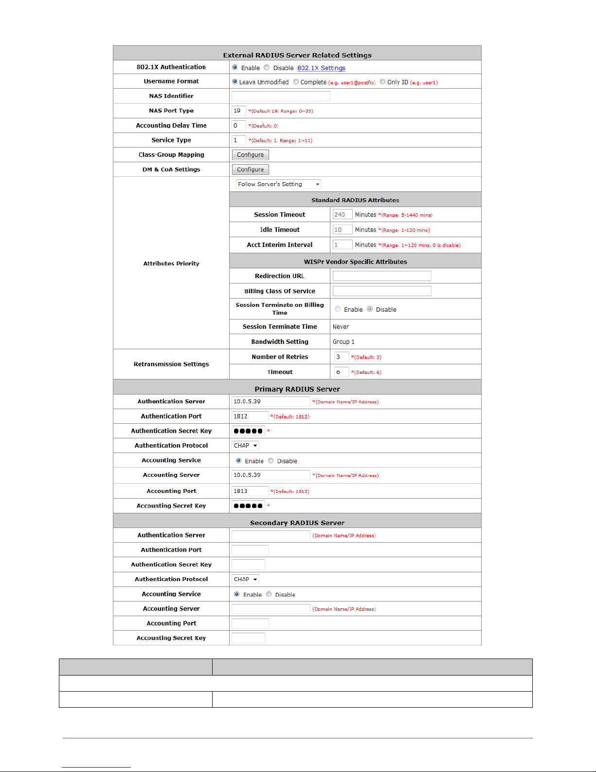
74
Item
Description
External RADIUS Server Related Settings
802.1X Authenticatio n
Enable /Disable 802.1X authenticati ons for us ers authentica ting through th is
Page 75
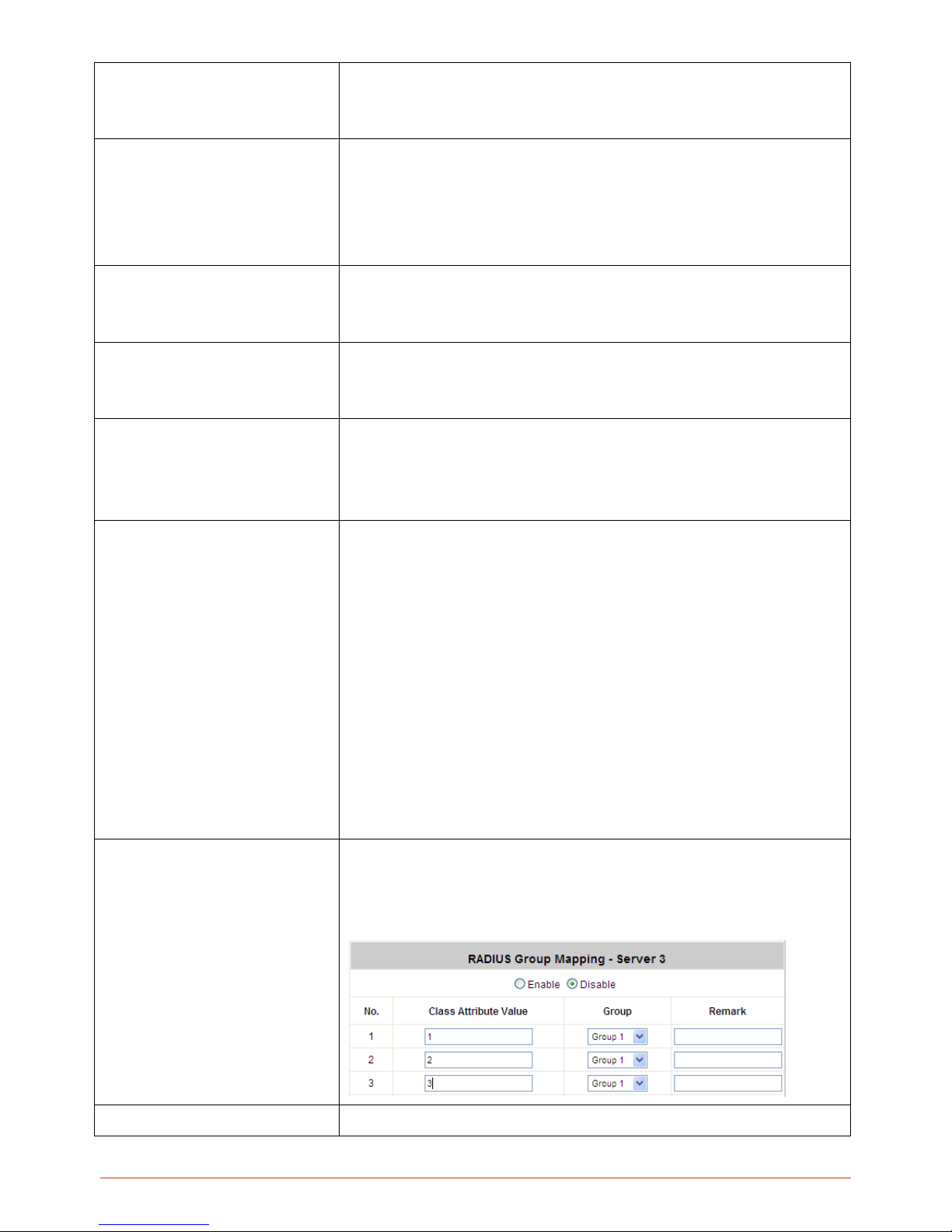
75
Server. To support EAP-SIM auth entication, please enable this feature and
enter 802.1X Settings to conf igure the AP’s that support as sociated clients
to authenticate by EAP-SIM.
Username Format
Select the format which the user login information is sent to the external
RADIUS Server. You ma y choose to sen d user name i n Complete ( userID +
Postfix), Only ID or Leave Unmodified
. Please note that if Leave
Unmodified option is selec t ed, t he system will send th e us ername to Default
Auth Server set in 802.1X configuration page for authentication.
NAS Identifier
This attribute is the string id entifying the NAS originatin g the ac ces s reques t.
System will send this val ue to the external RADIUS server, if the external
RADIUS server needs this.
NAS Port Type
Indicates the type of physical port the network access server is using to
authenticate the user. System will send this value to the external RADIUS
server, if the external RADIUS server needs this.
Accounting Delay Time
This attribute indicates ho w m an y seco nds the cl ien t h as been trying to send
this record for, and can be subtracted from the time of arrival on the server to
find the approximate tim e of the event generating this Accounting-
Request.
(Network transit time is ignored.)
Service Type
A RADIUS attribute with configurable range from 1 ~ 11. Each value represents
different kinds of service. The administrator can set the kind of service preferred by
users and notify the RADIUS server this way.
1 Login
2 Framed
3 Callback Login
4 Callback Framed
5 Outbound
6 Administrative
7 NAS Prompt
8 Authenticate Only
9 Callback NAS Prompt
10 Call Check
11 Callback Administrative
Class-Group Mapping
This function is to assign a Group to a RADIUS class attribute sent from the
RADIUS server. When the clients classified by RADIUS class attributes logs
into the system via the RADIUS server, each client will be mapped to an
assigned Group.
DM & CoA Settings
Under some circumstances, it may be desirable for a network
Page 76
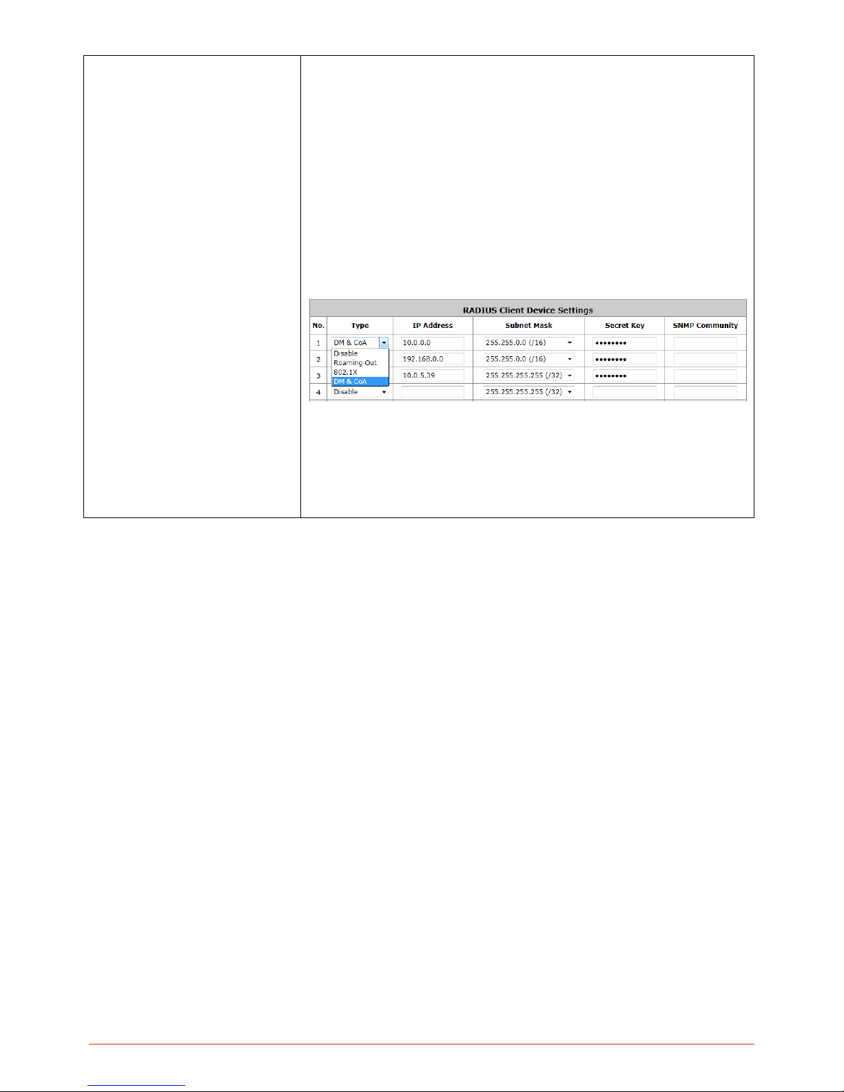
76
administrator to make changes in session characteristics
without requiring to access Controller WMI to initiate change.
For example, a network administrator may need to terminate a
session or change the authorization attributes associated with a
session. This is possible through RADIUS DM & CoA
messages.
Administrator can specify the white list of devices that the
Controller deem as authentic message source.
Devices configured here with correct shared key are allowed to
issue to Controller change of authorization (CoA) messages,
which affect session authorization, or disconnect messages
(DM), which cause a session to be terminated immediately.
Page 77

77
Attributes Priority
The drop down selection list allows 3 options: Follow Server’s
Setting, Overwrite Server’s Setting and Set if not presented.
If Follow Server’s Setting is selected, system will use the RADIUS
attributes set in the remote RADIUS server. If Overwrite Server’s
Setting is selected, system will use the RADIUS attributes set below.
If Set if not presented is selected, system will use the RADIUS
attribute settings below if the configured remote RADIUS server
presents no attributes.
RADIUS Standard Attributes
Session Time Out:
Forced logout once timeout period
reached.
Idle Time Out: Implicitly logout when inactivity timeout period
reached.
Acct Interim Interval: The time interv al to send accounting
updates.
WISPr Vendor Specific Attributes Default from the drop-down
menu is to follow external Server settings. If you select to overwrite or
set if not present, the following attributes w ill be requir e d.
Redirection URL: URL of Start page.
Billing Class Of Service: Text string used to indicate serv ice
used for the visitor access.
Session Terminate on Billing Time:
When enabled, the
session will terminate in the Billing Time set.
Session Terminate Time: Never. This means that RADIUS
sessions will only terminate when a user logouts, gets kicked
out, or session idled timeout.
Bandwidth Setting: It will f ollow the Bandwidth settin gs of the
Group profile set for this authentication server.
Retransmission
Settings
Bandwidth Setting: The number of resends before
treating this transaction as fail.
Timeout: The time in seconds to wait
for reply from
RADIUS server, if no reply then resend the packet.
Primary / Secondary RADIUS Server
Authentication
Server
Enter the domain name or IP address of your RADIUS Server.
Authentication Port
Enter the Port number used for authentication
Authentication
Secret Key
Secret Key used for authentication
Authentication
Select Challenge-Handshake Authentication Protocol (CHAP) or
Page 78
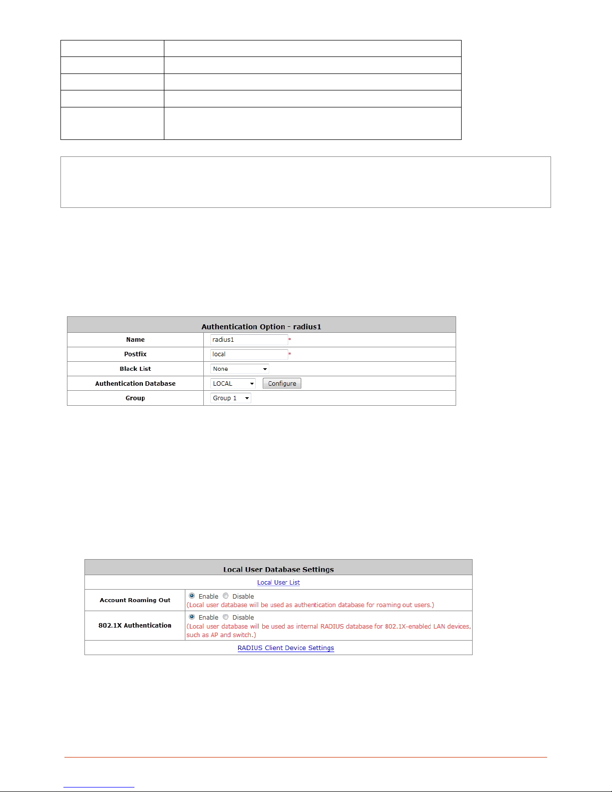
78
Protocol
Password Authentication Protocol (PAP).
Accounting Service
Enable / Disable RADIUS accounting
Accounting Server
Enter the Accounting Server domain name or IP address.
Accounting Port
Enter the Port number used for accounting
Accounting Secret
Key
Secret Key used for accounting.
Note: The Authentication Server and Accounting Service operates in sets, which means if the Authentication Server
set under Primary RADIUS Server is unavailable then the system will refer to Secondary RADIUS Server setting
without referencing the Accounting service settings under Primary.
6.1.3. Configuring Local
Local is the Controller’s built-in static user account database. The number of user account supported will be different for different
models. Please refer to the specification details for capacity number of your WHG Controller model.
Name: Configurable text string designated as the mnemonic name of this authentication option.
Postfix: Is the text string entered as a postfix in the account field for notifying the Controller which
authentication database this account belongs to.
Black List: System has built-in black-list profiles where specific user accounts can be listed. When selected
and applied here, it tells the Controller that the accounts on the selected black list should be denied
authentication.
Group: The Group profile that will govern the users authenticated via this authentication option.
Authentication Database: Select the authentication database that will be used for account validation when
an authentication request is received. Click the button Configure for further configuration.
Local User List
The link will redirect to Local User List page where all Local users on the Controller’s built-in Local database will be displayed.
The page has an
Upload User button for importing a list of user account from a text file and a Download User button
Page 79
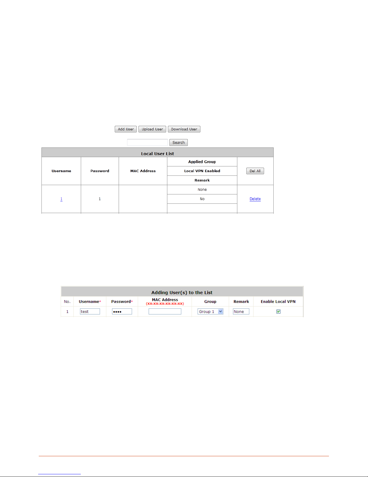
79
for exporting all local user accounts into a text file. Clicking on each user account leads to a page for configuring the
individual local account. Local user account can be assigned a Group and applied Local VPN individually.
Search: Enter a keyword of a username to be searched in the text filed and click this button to perform the
search. All usernames matching the keyword will be listed.
Del All: Click on this button to delete all the users at once or click on Delete to delete the user individually.
Edit User: If editing the content of individual user account is needed, click the username of the desired user
account to enter the User Profile Int erface for that particular user, and then modify or add any desired
information such as Username, Password, MAC Address (optional), Applied Group (optional), Enable Local
VPN (optional) and Remark (optional). Click Apply to complete the modification.
Add User: Click this button to enter into the Adding User(s) to the List interface. Fill in the necessary
information such as “Username”, “Password”, “MAC Address”, and “Remark”. Select a desired Group to
apply to this local user account. Check to enable Local VPN in the Enable Local VPN column if you wish to
establish a VPN link between the Controller and user dev ice us ing this loc a l acco unt. Click Apply to complete
adding the user(s). MAC address entered here means that a networking device can be bound with a local user
as well. Therefore user must login to system with a networking device (PC) that has this MAC address, so this
user can not login with other networking device.
6.1.4. Configuring LDAP
The Lightweight Directory A c ce ss Protocol (LDAP) is an application protocol for reading and edit in g
directories over an IP network.
Page 80
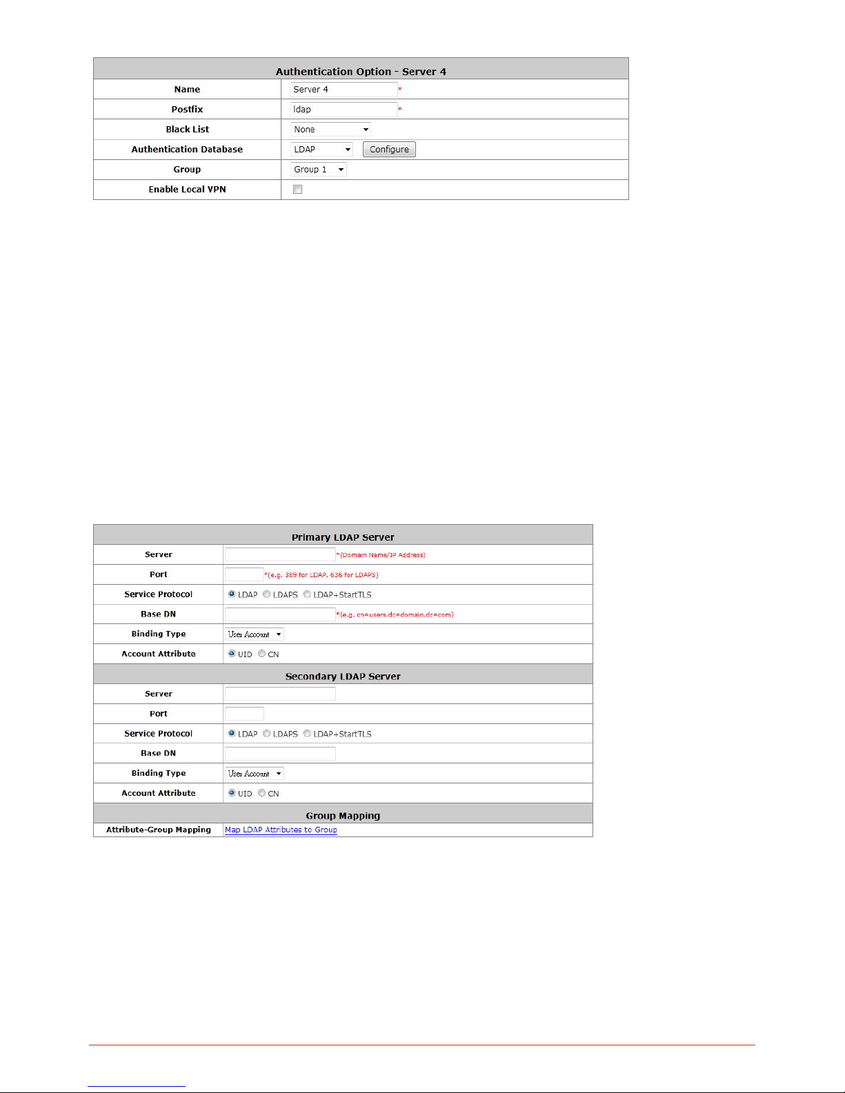
80
Name: Configurable text string designated as the mnemonic name of this authentication option.
Postfix: Is the text string entered as a postfix in the account field for notifying the Controller which
authentication database this account belongs to.
Black List: System has built-in black-list profiles where specific user accounts can be listed. When selected
and applied here, it tells the Controller that the accounts on the selected black list should be denied
authentication.
Group: The Group profile that will govern the users authenticated via this authentication option.
Enable Local VPN: When checked, users authenticating with this authentication option will have a VPN
tunnel established automatically between the Controller and the user’s client device.
Authentication Database: Select the authentication database that will be used for account validation when
an authentication request is received. Click the button Configure for further configuration. Enter the
information for the primary server and/or the secondary server (the secondary server is not required). The
blanks with red asterisk are necessary information which should be filled in. These settings will become
effective immediately after clicking the Apply button.
Server: The IP address of the external LDAP server.
Port: The authentication port of the external LDAP server.
Service Protocol: The protocol used to communicate with the external LDAP server can be LDAP, LDAPS,
or LDAP+StartTLS depending on the protocol type supported on your LDAP server.
Base DN: The Base DN (Distinguished Name) is the LDAP search base, telling which part of the external
directory tree to search from. Think of the Base DN as the “top” of the directory for your LDAP users
although it may not always be the top of the directory itself. The search base may be something equivalent
Page 81
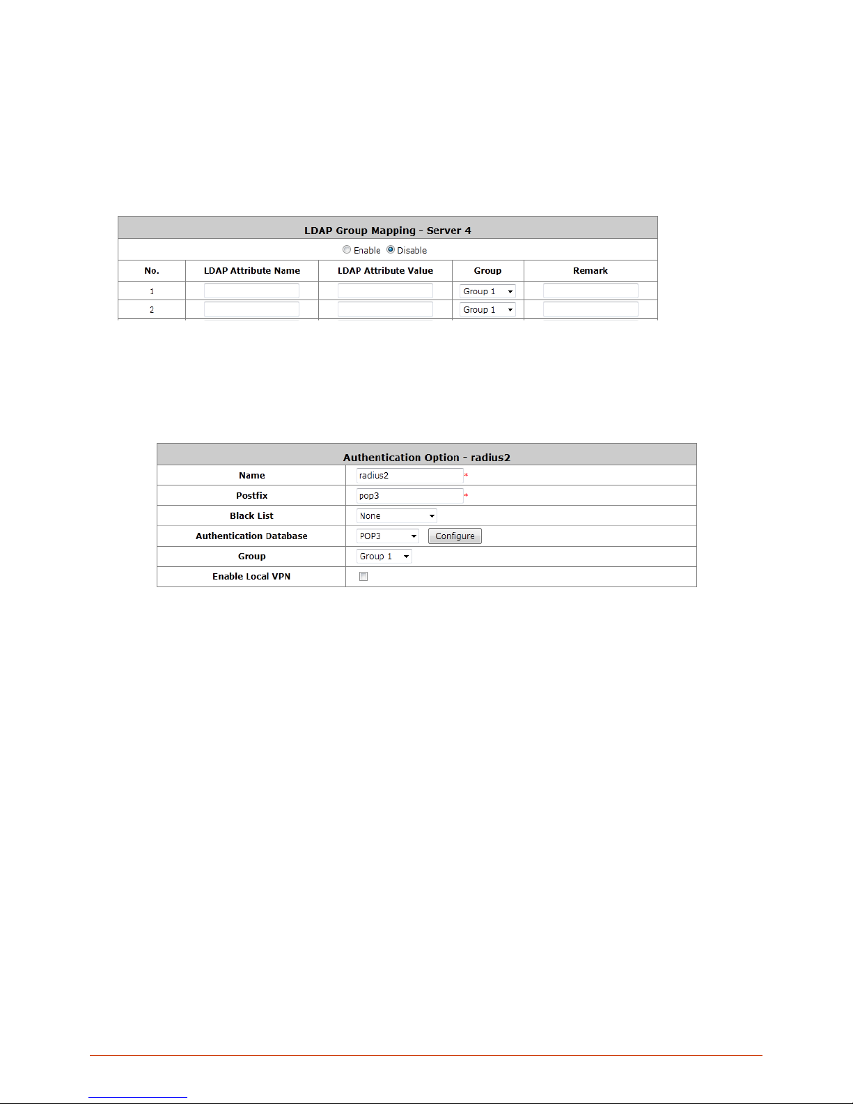
81
to the organization, group, or domain name (AD) of external directory.
Binding Type: This specifies the binding type and search scope for LDAP authentication with 4 binding
types available: User Account, Anonymous, Specified DN and Windows AD.
Account Attribute: The attribute of LDAP accounts.
Attribute-Group Mapping: The administrator can specify the mapping of specific LDAP attributes (name
and value) to Group profiles. When enabled, users login into the network with an LDAP account will have
his/her user group determined based on the LDAP attribute the account carries.
6.1.5. Configuring POP3
Choose “POP3” from the Authentication Database field. Except Local authentication, the Local VPN option in
other authentication option only can be enabled or disabled for the entire Authentication Database.
Name: Configurable text string designated as the mnemonic name of this authentication option.
Postfix: Is the text string entered as a postfix in the account field for notifying the Controller which
authentication database this account belongs to.
Black List: System has built-in black-list profiles where specific user accounts can be listed. When selected
and applied here, it tells the Controller that the accounts on the selected black list should be denied
authentication.
Group: The Group profile that will govern the users authenticated via this authentication option.
Enable Local VPN: When checked, users authenticating with this authentication option will have a VPN
tunnel established automatically between the Controller and the user’s client device.
Authentication Database: Select the authentication database that will be used for account validation when
an authentication request is received.
Click the button of Configure for further configuration. Enter the information for the primary server and/or the
secondary server (the secondary server is not required). The fields with red asterisk are necessary information.
These settings will become effective immediately after clicking the Apply button.
Page 82
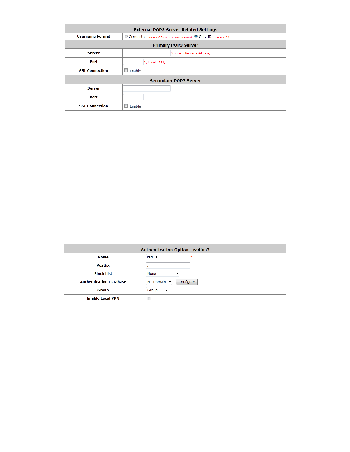
82
Username Format: When Complete option is checked, both the username and postfix will be transferred to
the server for authentication. When Only ID option is checked, only the username will be transferred to the
external server for authentication.
Server: The IP address of the external POP3 Ser ver.
Port: The authentication port of the external POP3 Server.
SSL Connection: The system supports POP3S. Check the check box beside to Enable SSL Connection
to POP3.
6.1.6. Configuring NT Domain
Choose “NT Domain” from the Authentication Database field. Except Local authentication, the Local VPN option
in other authentication option only can be enabled or disabled for the entire Authentication Database.
Name: Configurable text string designated as the mnemonic name of this authentication option.
Postfix: Is the text string entered as a postfix in the account field for notifying the Controller which
authentication database this account belongs to.
Black List: System has built-in black-list profiles where specific user accounts can be listed. When selected
and applied here, it tells the Controller that the accounts on the selected black list should be denied
authentication.
Group: The Group profile that will govern the users authenticated via this authentication option.
Enable Local VPN: When checked, users authenticating with this authentication option will have a VPN
tunnel established automatically between the Controller and the user’s client device.
Authentication Database: Select the authentication database that will be used for account validation when
an authentication request is received.
Click the button Configure for further configuration. Enter the server IP address and enable/disable the transparent
Page 83

83
login function. These settings will become effective immediately after clicking the Apply button.
Server: The IP address of the external NT Domain Server.
Transpar ent Login: This function refers to Windows NT Domain single sign-on. When Transparent Login is
enabled, clients will log into the system automatically after they have logged into the NT domain, which
means that clients only need to log in once.
o Enable Local VPN: Check the checkbox to enable local VPN under transparent login mode. When
enabled, local VPN connection will be automatically created under transparent login mode. For the
local VPN to work under transparent login mode, however, it requires support from Windows Server
– need to install additional logon script on Windows Server.
6.1.7. Configuring SIP
SIP (Session Initiation Protocol) is a protocol for making real-time calls over IP network. Currently, most of the SIP
extensions address audio communication. Controller can act like a SIP Proxy Server that forwards end point’
requests and responses. In other words, SIP Proxy server needs to log in the trusted registrar to verify identities of 2
clients. After enabling SIP proxy server, all SIP traffic pass through NAT with a selective but fixed WAN interface.
In this example, client extension #301 is trying to call #303. Controller asks an external trusted SIP registrar to verify
both identities. After SIP registrar responds with a YES, call is established through WHG-707.
Page 84
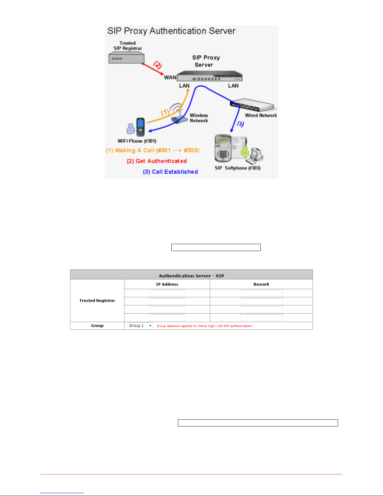
84
The system provides SIP proxy for SIP clients (devices or soft clients) pass through NAT. After enable SIP proxy
server, all SIP traffic can pass through NAT with a selective but fixed WAN interface. If the SIP Registrar settings in
SIP client is same as the system setting, when the client try to access the SIP Registrar, system will let this client
login automatically and all SIP traffic can pass through.
Configure Dynamic Domain Name Service, go to: Users >> Authentication >> SIP.
SIP: SIP authentication supports 4 Trusted SIP Registrar.
IP Address: The IP address of the Trusted SIP Registrar.
Remark: The administrator can enter extra information in this field for remark.
Group: A Group option can be applied to the clients who login with SIP Authentication. Be noted that the
specific route of the applied Policy for the selected Group cannot conflict with the assigned WAN interface
for SIP authentication.
SIP Interface Configuration
To configure Dynamic Domain Name Service, go to: System >> Service Zones >> Service Zone Configuration.
Page 85
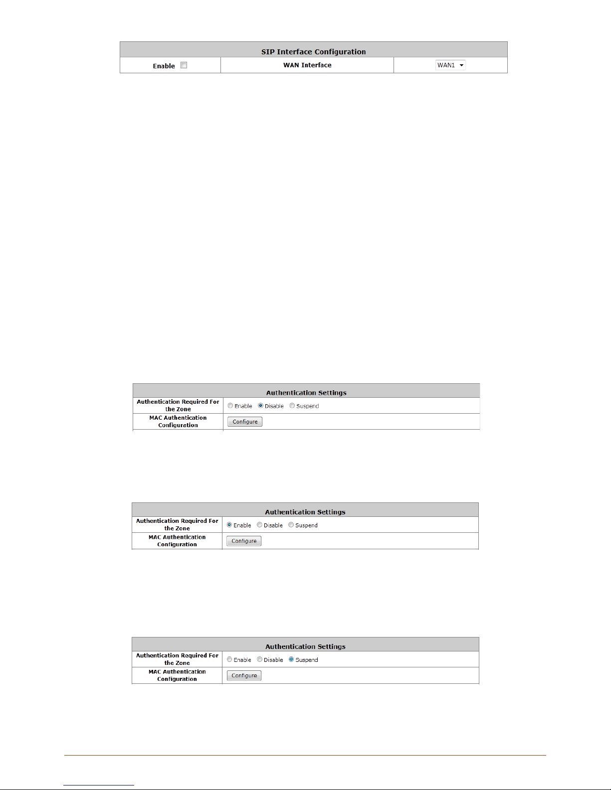
85
The system provides SIP proxy functionality, which allows SIP clients to pass through NAT. When enabled, all SIP
traffic can pass through NAT via a fixed WAN interface. The policy route setting of SIP Authentication must be
configured carefully because it must cooperate with the fixed WAN interface for SIP authentication.
SIP Transparent Proxy can be activated in both NAT and Router mode. SIP Authentication must support in either
mode. For users logging in through SIP authentication, a group can be chosen to govern SIP traffic. The policy’s
login schedule profile will be ignored for SIP authentication. Specific route and firewall rules of the chosen group will
be applied to SIP traffic.
6.1.8. Choosi ng Your Networks’ Authentication method
For each Service Zone, network administrator can choose to enable or disable the need for authentication for that
Service Zone.
Go to: Main Menu > System > Service Zones
Disabling the need to authenticate means that all users accessing the network via this Service Zone will not need to
be authenticated before gaining access to the internet, however this way means that all users under this Service
Zone will not be able to be enforced with different policies.
Enabling the need to authenticate means that any user accessing this Service Zone will need to be authenticated
first before gaining access to the internet. The users’ Group will be determined depending on which type of
authentication server this user belongs to and therefore different authentication server’s users in the authentication
required Service Zone can be bounded with different policies as set in Service Zone – Gro up Map pin gs .
Suspending a Service Zone’s need to authenticate means that no newly connected users are allowed to access this
Service Zone until it is configured back to either enabled or disabled by the network administrator.
Page 86
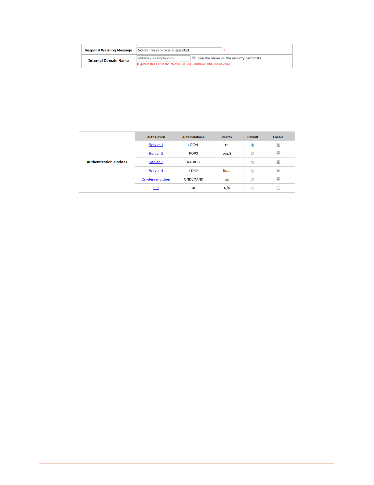
86
A warning message can be customized at Main Menu > System > General page which will be displayed on the web
browser of newly connected users when a Service Zone’s authentication is under the Suspend status.
The purpose of this feature is to prevent further loading to this Service Zone when network administrator needs to
make changes to the Service Zone configurations. Once the configuration change is done and suspend is changed
back to enable, currently online users of this service zone will be disconnected and request to re-authenticate.
Once you have enabled the need to authenticate for a Service Zone, which types of authentication servers allowed
can be configured in the same page.
All of the pre-configured authentication servers can be seen here. Under the “Enable” column, check the
authentication servers that you wish to allow access to this service zone. In other words if an authentication server is
checked here, its users can access this service zone after a successful login. One authentication server can be
selected as “Default”, this means that users of this authentication server can omit the postfix during login.
Page 87

87
6.2. Users Group
Group profiles are used to divide users based on role. A Group profile can be designated for differentiating a group
of users with similar statuses e.g. Student, Staff, Guest, etc.; Network administrator can determine which Service
Zones are accessible to a certain Group as well as the Policy that will govern the user. Therefore users belonging to
a certain Group profile may be allowed to access many Service Zones and be govern by different policies under
different Service Zone, depending on how the network administrator setup the Group – Service Zone mapping.
Configure Group settings; go to: Users >> Group.
Screenshot above illustrates an example for Group 1. By checking the “Enable” check box of corresponding Service
Zone, it means that users from Group 1 are allowed to access these Service Zones (allowed authentication). Policy
that will be applied can also be selected here.
Page 88
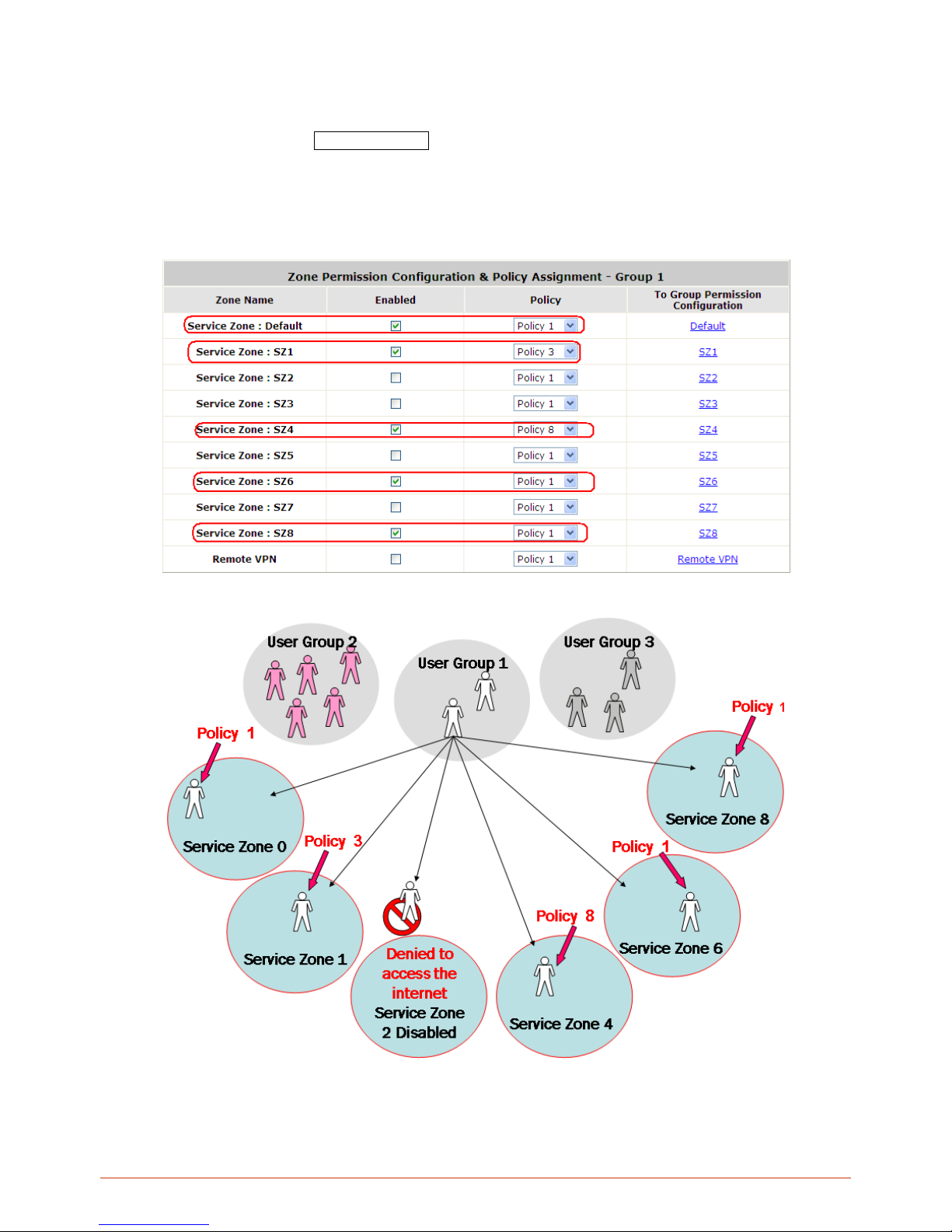
88
6.2.1. Assign us e rs to a Group
Configure Group settings; go to: Users >> Group.
This section shows how to group users, how to rule each grouped user with different policy as he moves to different
service zone. The following examples will help you better understand this section.
Page 89
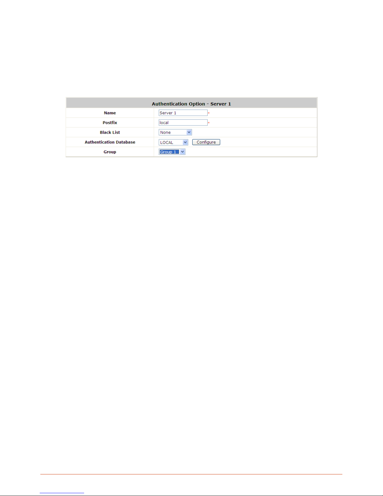
89
In this example, Group 1 users are allowed to access the internet in 5 places; Service Zone 0,1,4,6, and 8. They
must follow policy 1 at Service Zone 1, 6 and 8. They are ruled by Policy 3 at Service Zone 1 and by Policy 8 at
Service Zone 4.
In each authentication option, you can assign a Group with each authentication option. All users login with same
authentication server will belong to same Group.
But there are some exceptions:
In Local Authentication, each user can assign to different Group one by one.
In RADIUS Authentication, the users can assign to different Group by Class-Group Mapping.
In LDAP A uthentication, the users can assign to different Group by Attribute-Group Mapping.
Page 90
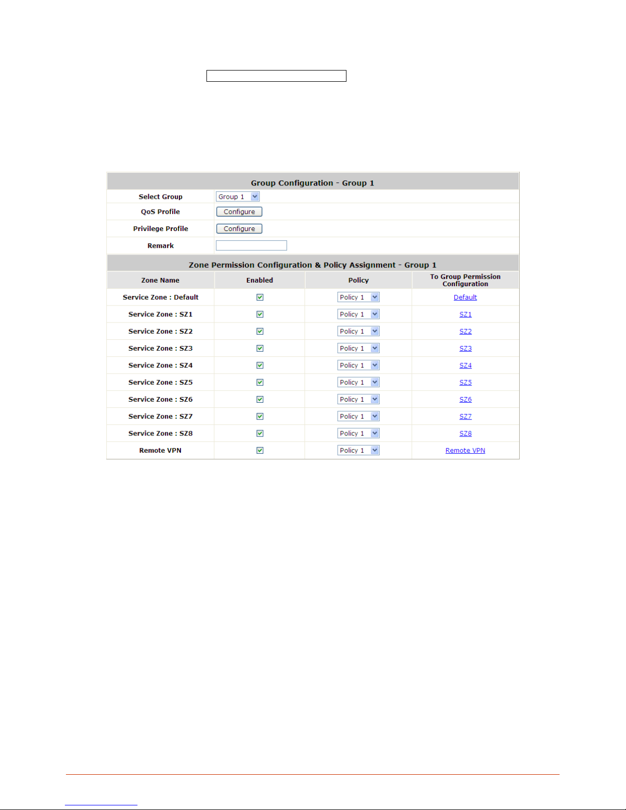
90
6.2.2. Permission in Service Zone
Configure Group settings; go to: User Authentication >> Group.
A Group can be allowed to access one Service Zone or multiple Service Zones. Moreover, a Group can be applied
different Policies within different Service Zones. Remote VPN is considered as a zone, where clients log into the
system via remote VPN.
Zone Name: The name of Service Zones and Remote VPN.
Enabled: Select Enabled to allow clients of this Group to log into the selected Service Zones. For
example, the above figure shows that users in Group 1 can access network services via every Service
Zone as well as Remote VPN under constraints of Policy 1.
Policy: Select a Policy that the Group will be applied with when accessing respective Service Zones.
To Group Permission Configuration: The relation between Group and Service Zone is many to many;
every Group can access network services via more than one Service Zone, and meanwhile, each Service
Zone can serve more than one Group.
Click the hyperlink in the To Grou p Permission Configuration column to enter the Group Configuration
interface, which is based on the role of Service Zone, to configure the relation between Group and Service
Zone.
Page 91
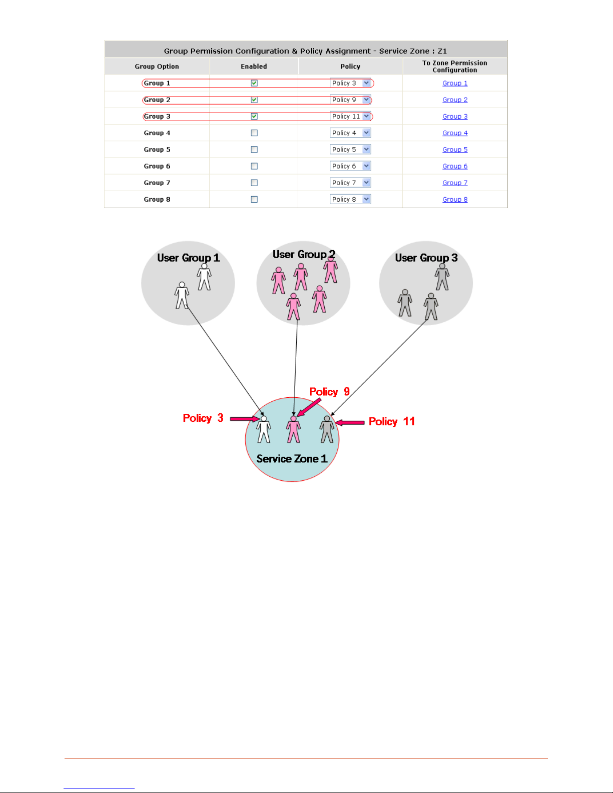
91
At Service Zone 1, Group 1 user is ruled by Policy 3. Group 2 is by Policy 9 and Group 3 is by Policy 11. Other
Groups are not enabled to access Service Zone 1.
Page 92
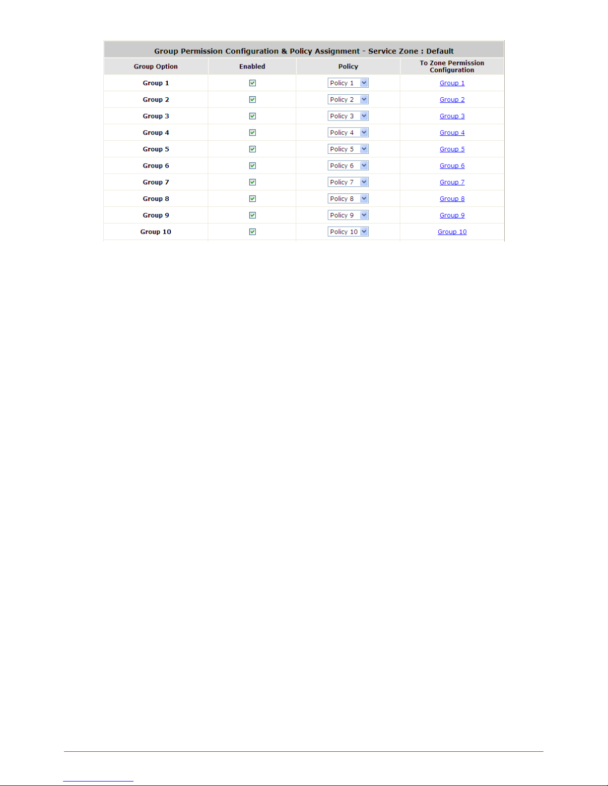
92
o Group Option: The name of Group options available for selection.
o Enabled: Select Enabled to allow clients of the enabled Groups to log in to this Service Zone under
constraints of the selected Policies.
Check Enabled of each individual Group to assign it to the Service Zone listed.
o Policy: Select a Policy that the Group will be applied with when accessing this Service Zone.
o To Zone Permission Configuration: Click the hyperlink in the To Z o n e Permission Configuration
column to enter Zone Permission Configuration & Policy Assignme nt interface, which is based on
the role of Group, to configure the relation between Group and Zone.
Page 93
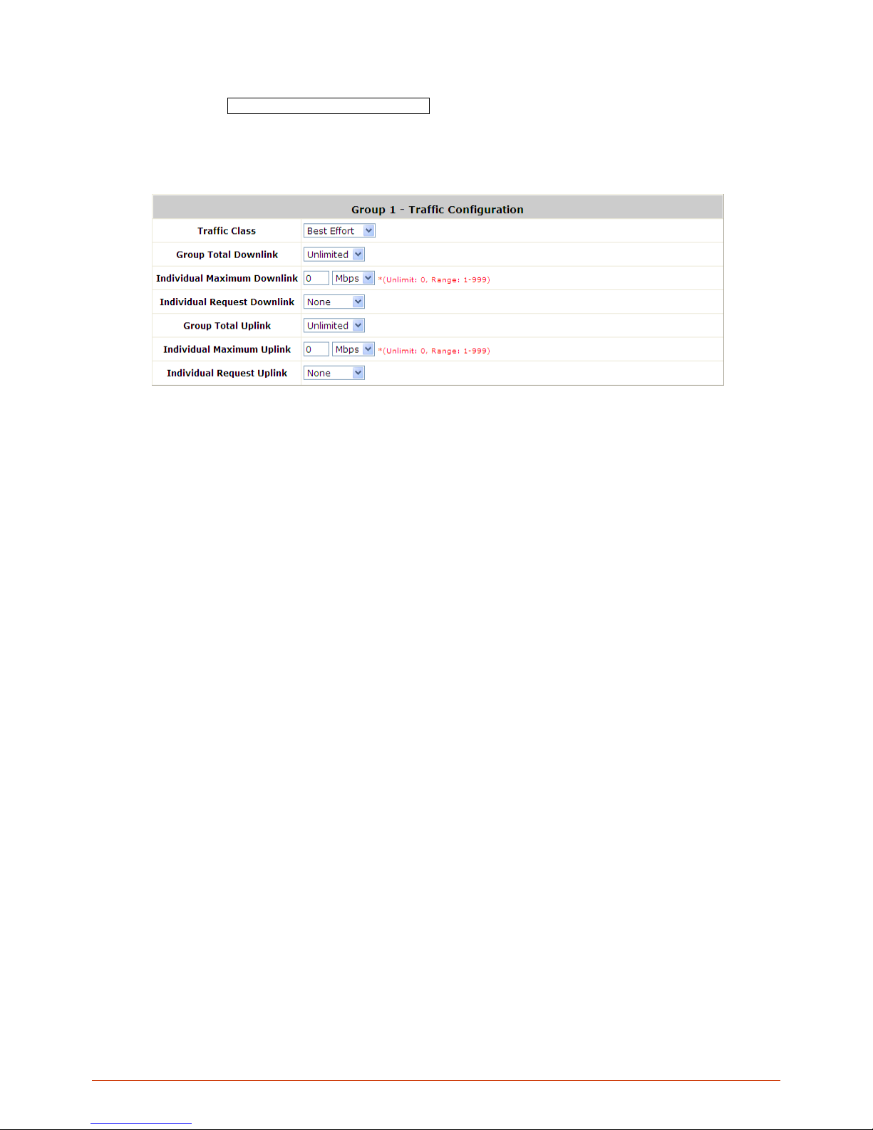
93
6.2.3. QoS Traffic Class and Bandwidth Control
Configure QoS; go to: Users >> Group >> QoS Profile.
QoS Profile: Set parameters for traffic classification.
o Traffic Class: A Traffic Class can be chosen for a Group of users. There are four traffic classes:
Voice, Video, Best-Effort and Background. Voice and Video traffic will be placed in the high priority
queue. When Best-Effort or Background is selected, more bandwidth management options such as
Downlink and Uplink Bandwidth will appear.
o Group Total Downlink: Defines the maximum bandwidth allowed to be shared by clients within this
Group.
o Individual Maximum Downlink: Defines the maximum downlink bandwidth allowed for an individual
client belonging to this Group. The Individual Maximum Downlink cannot exceed the value of Group
Total Downlink.
o Individual Request Downlink: Defines the guaranteed minimum downlink bandwidth allowed for an
individual client belonging to this Group. The Individual Request Downlink cannot exceed the value of
Group Total Downlink and Individual Maximum Downlink.
o Group Total Uplink: Defines the maximum uplink bandwidth allowed to be shared by clients within
this Group.
o Individual Maximum Uplink: Defines the maximum uplink bandwidth allowed for an individual client
belonging to this Group. The Individual Maximum Uplink cannot exceed the value of Group Total
Uplink.
o Individual Request Uplink: Defines the guaranteed minimum bandwidth allowed for an individual
client belonging to this Group. The Individual Request Uplink cannot exceed the value of Group Total
Uplink and Individual Maximum Uplink.
Page 94
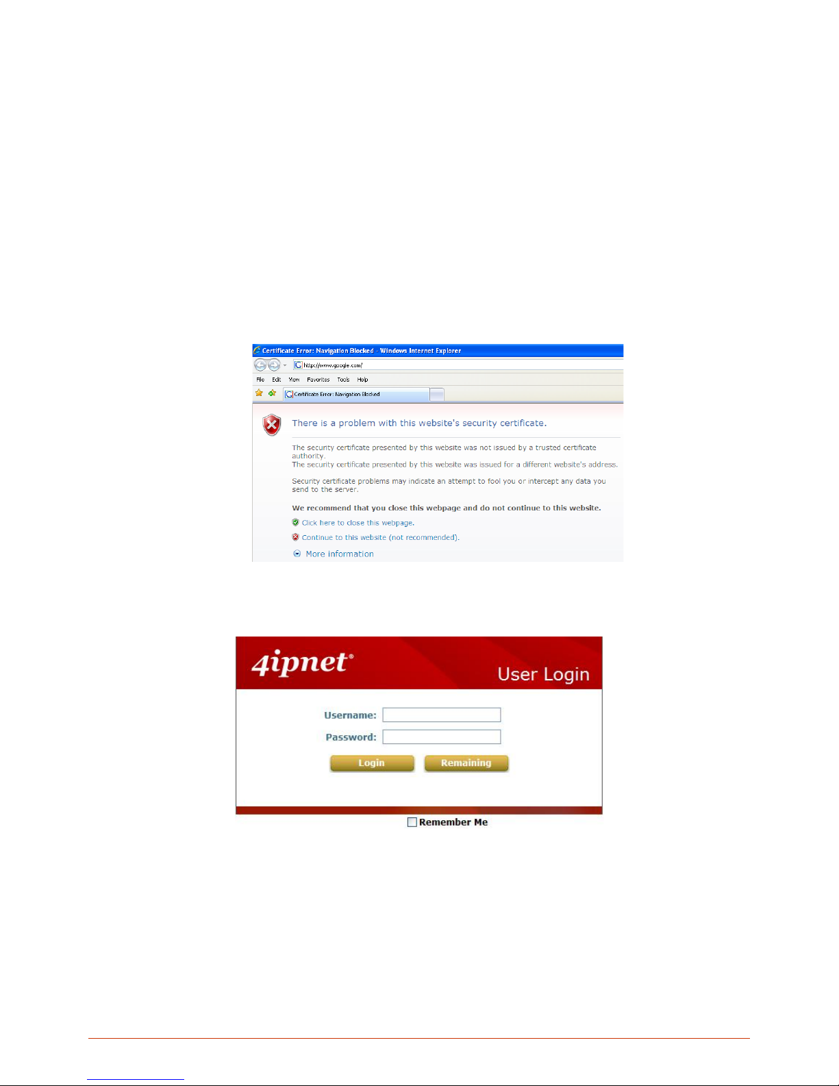
94
6.3. User Login
6.3.1. An Example of User Login
Normally, users will be authenticated before they get network access through WHG Controller. This section presents
the basic authentication flow for end users. Please make sure that the WHG Controller is configured properly and
network related settings are done.
1. Open an Internet browser and try to connect to any website (in this example, we try to connect to
www.google.com).
a) For the first time, if the WHG Controller is not using a trusted SSL certificate, there will be a “Certificate
Error”, because the browser treats WHG Controller as an illegal website.
b) Please press “Continue to this website” to continue.
c) The default user login page will appear in the browser.
2. Enter the username and password (for example, we use a local user account: test@local here) and then click
Submit button. If the Remember Me check box is checked, the browser will remember this user’s name and
password so that he/she can just click Submit next time he/she wants to login.
Check the Remember Me box to store the username and password on the current computer in order to
automatically login to the system at next login. Then, click the Submit button.
The Remaining button on the User Login Page is for on-demand users only, where they can check their
Page 95
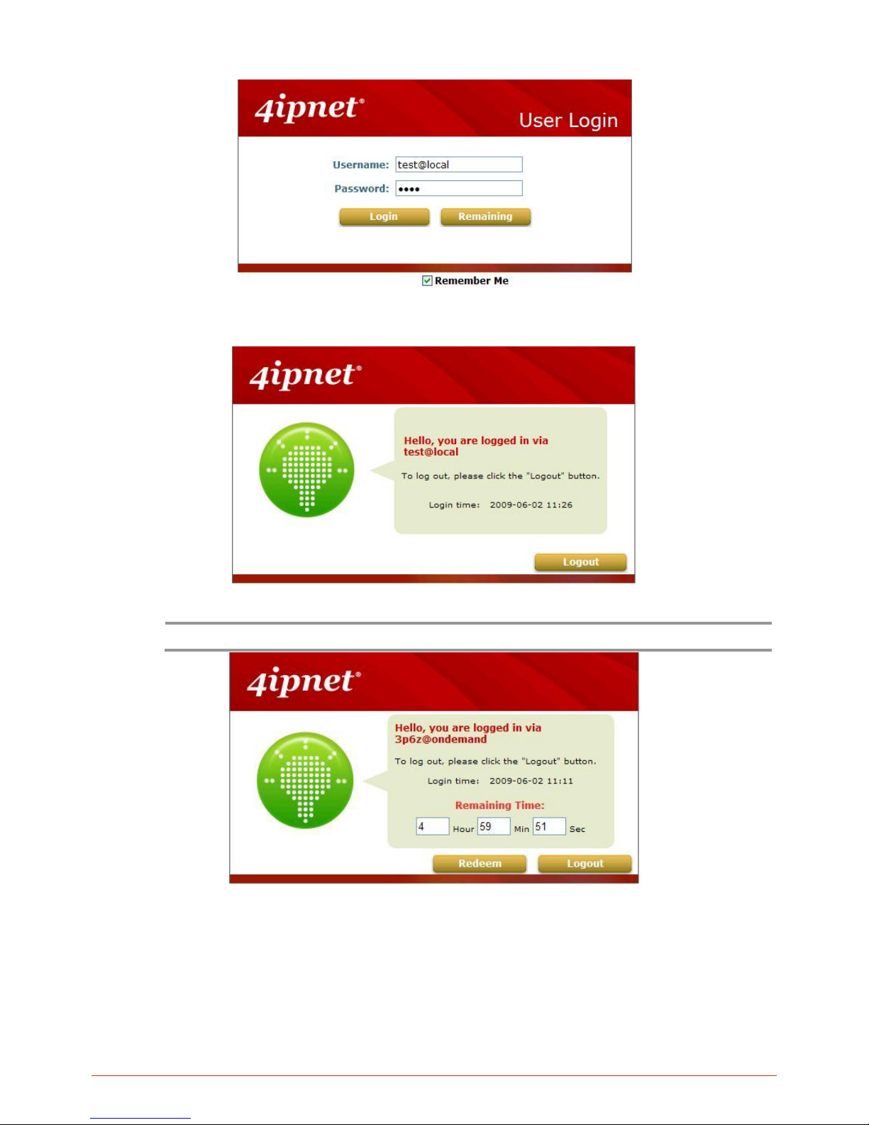
95
Remaining quota.
3. Successful! The Login Successful page appearing means you are connected to the network and Internet now!
Note:
When On-demand accounts are used, the system will display more information, as shown below.
Page 96

96
6.3.2. Default Authentication
In each Service Zone, there are different types of authentication database (LOCAL, POP3, RADIUS, LDAP,
NTDOMAIN, ONDEMAND, and SIP) that are supported by the entire system. There are up to six
authentication servers can be enabled, two of them constantly as Ondemand and SIP, and one of them can
be set as the Default Authentication– so that users do not have to type in the postfix string while entering
username during login.
A postfix is used to inform the system which authentication option to be used for authenticating an account
(e.g. bob@BostonLdap or tim@TaipeiRadius) when multiple options are concurrently in use. One of
authentication option can be assigned as default. For authentication assigned as default, the postfix can be
omitted. For example, if "BostonLdap" is the postfix of the default option, Bob can login as "bob" without
having to type in "bob@BostonLdap”.
6.3.3. Login with Postfix
Set a postfix that is e asy to relate (e.g. Loca l) user login with which authenticati on server. The acceptable
characters are num ber s (0~9), alphabets (a~z or A ~Z), das h ( -), underline (_) and dot (. ) with in a maximum
of 40 characters. All other characters are not allowed.
Beside the Default Authent ication, all other authen tication server us ers need to key in postf ix in username
during login in order for the Controller to recognize which authentication server to authenticate against.
Page 97
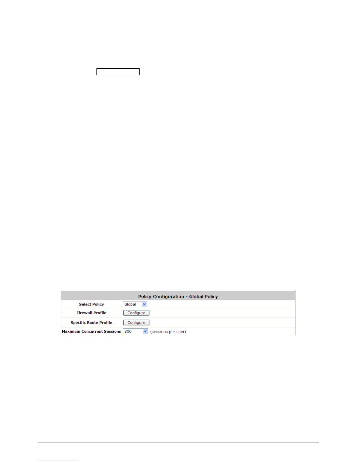
97
7. Policies and Access Control
7.1. Policy
Configure Policy; go to: Users >> Policy.
WHG Controller supports multiple Policies, including one Global Policy and individual Policies. Each Policy
consists of access control profiles that can be configured respectively and applied to a certain Group of users.
Global Policy is the system’s universal policy and applied to all clients, while other individual Policy can be selected
and defined to be applied to any Service Zone.
The clients belonging to a Servic e Zone w ill be boun d by an applied Po lic y. In addition, a Policy can be applied at a
Group basis; a Group of users can be bound by a Policy. The same Group can be applied with different Policies
within different Service Zones.
When the type of authentication database is RADIUS, the Class-Group Mapping function will be available to allow
the administrator to assign a Group for a RADIUS class attribute; therefore, a Policy applied to this Group will be
mapped to a user Group of a RADIUS class attribute.
When the type of authentication database is LDAP, the Attribute-Group Mapping function will be available to allow
the administrator to assign a Group for LDAP attribute; therefore, a Policy applied to this Group will be mapped to a
user Group of a LDAP attribute.
When the type of database is Local, the Group selection function will be available to allow the administrator to
assign a Group to each user one by one.
Global Policy
Global is the system’s universal policy including Firewall Rules, Specific Routes Profile and Maximum
Concurrent Session which will be applied to all users unless the user has been regulated and applied with another
Policy.
Select Policy: Select Global to set the Firew all Profile, Specific Route Profile and Maximum Concurrent
Session.
Firewall Profile: Glob al policy and eac h policy have a firewall ser vice list and a s et of firewa ll profile which is
composed of firewall rules.
Specific Route Profile: The default gateway of WAN1, WAN2, or a d esired IP address can be defined in a
policy. When Specific Default Route is enabled, all clients applied this policy will access the Internet through this
gateway settings, include default gateway.
Maximum Concurrent Sessions: Set the maximum concurrent sessions for each client.
Page 98
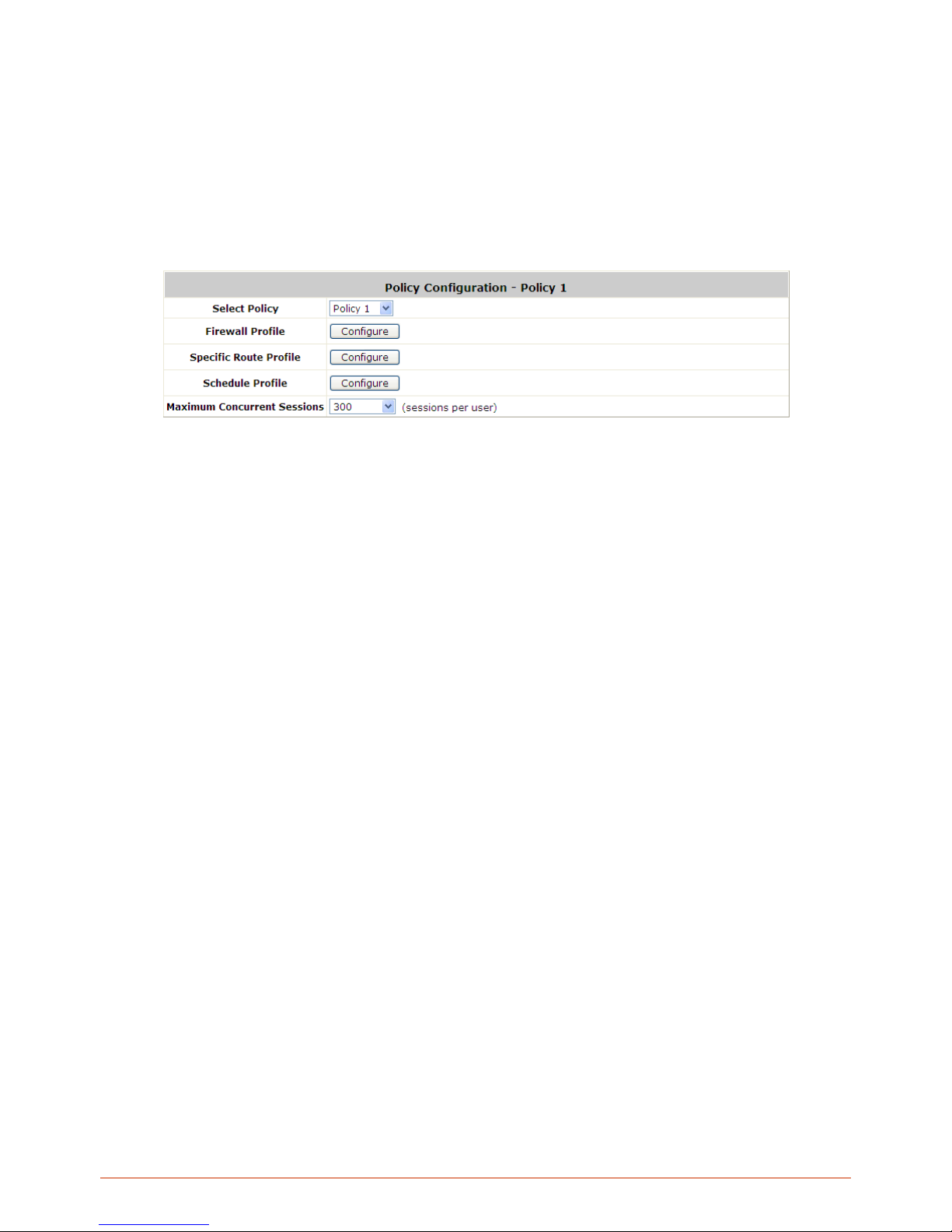
98
Policy 1 ~ Policy n
Beside Global Policy, there are Policy1 to Policy n (different models have different number of Policy), each Policy
consists of access control profiles that can be configured respectively and applied to a certain Group of users. The
clients belonging to a Service Zone will also be bound by an applied Policy. In addition, a Policy can be applied at a
Group basis; a Group of users can be bound by a Policy. The same Group can be applied with different Policies
within different Service Zones.
Select Policy: Select Policy 1~Policy n to set the Firewall Profile, Specific Route Profile, Schedule Profile
and Maximum Concurrent Sessions.
Firewall Profile: Each Policy has a firewall service list and a set of firewall profile consisting of firewall rules.
Specific Route Profile: The default gateway of WAN1, WAN2, or a desired IP address can be defined in a
policy. When Specific Default Route is enabled, all clients applied this policy will access the Internet through this
gateway settings, include default gateway.
Schedule Profile: The Schedule table in a 7X24 format is used to control the clients’ login time. When Schedule
is enabled, clients applied policies are only allowed to login the system at the time which is checked in the
applied policy.
Maximum Concurrent Sessions: Set the maximum concurrent sessions for each client.
Page 99
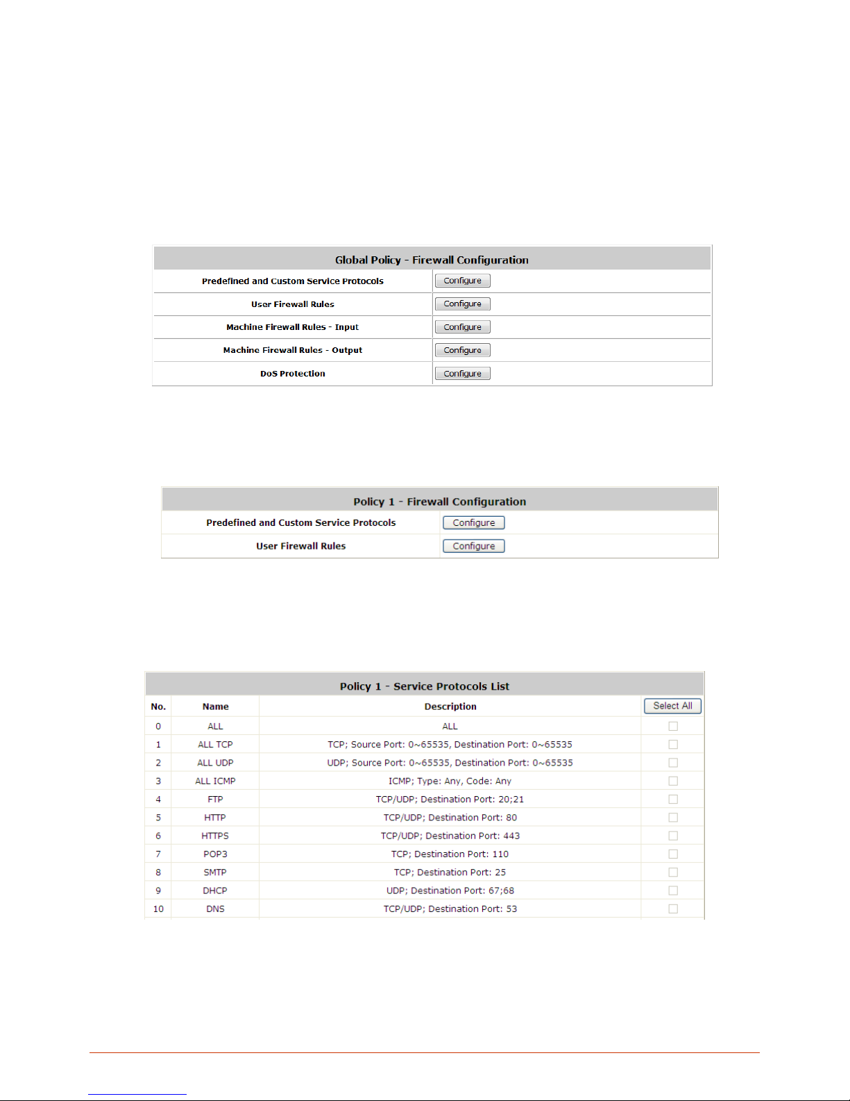
99
7.1.1. Firewall
Firewall Profile (Global P olicy): Click Setting for Firewall Profile. The Fire wall Configuration will appear. Click
Predefined and Custom Service Protocols to edit the pr otocol list. Click U ser Firewall Rules to edit the rules.
Machine Firewall Rules – Input is for editing firewall rules which will be enforced on traffics entering the WAN ports
from the external networ k. Machine Firew all Rules – Output is for editing firewall rules which will b e enforced o n
outgoing traffics fr om the internal network passing WAN ports. DoS Protection allows the administrator to sel ect
which type of attack to block by clicking the Enable checkbox.
Firewall Profile (Policy 1, Policy 2, and etc.): Click Setting for Firewall Profile. T he Firewall Configuration will
appear. Click Predefined and Custom Service Protocols to edit the protocol list. Click User Firewall Rules to edit
the rules.
Predefined Protocols
Predefined and Custom Service Protocols: There are predefined service protocols available for firewall rules
editing.
The administrator is able to add new custom service protocols by clicking Add, and delete the added protocols with
Select All and Delete operations.
Page 100
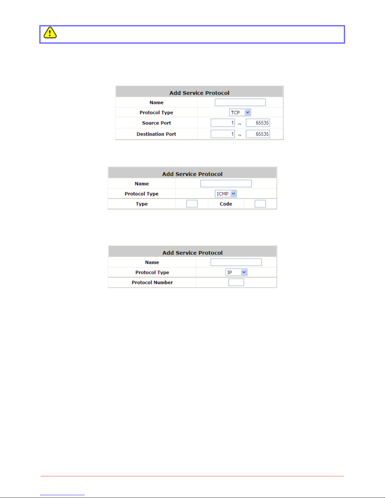
100
The Predefined Service Protocols can not be deleted.
Click Add to add a custom service protocol. The Protocol Type can be defined from a list of service by protocols
(TCP/UDP/ICMP/IP); and then define the Source Port (range) and Destination Port (range); click Apply to save
this protocol .
If the Protocol Type is ICMP, it will need to define Type and Code.
If the Protocol Type is IP, it will need to define Protocol Number.
Rules
After the custom protocol is defined or just use the Predefined Service Protocols, you will need to enable the
Firewall Rule to apply these protocols.
o Firewall Rules: Click the number of Filter Rule No. to edit individual rules and click Apply to save the
settings. The rule status will show on the list. Check “Active” checkbox and click Apply to enable that
rule.
This link leads to the Firewall Rules page. Rule No.1 has the highest priority; Rule No.2 has the second
priority and so on. Each firewall rule is defined by Source, Destination and Pass/Block action. Optionally,
a Firewall Rule Schedule can be set to specify when the firewall rule is enforced. It can be set to Always,
Recurring or One Time.
 Loading...