

Page 1

Introduction
WGR-2301
AC750 Dualb Bandb Wireless Gigabit,
Dual WAN, VPN
User Manual
V1.0
Digital Data Communications Asia Co., Ltd.
http://www.level1.com
http://www.level1.com Page 1
Page 2

Introduction
Table of Contents
Table of Contents ..................................................................................................................... 2
0.1 Factory settings .......................................................................................................... 6
0.2 Contact Us.................................................................................................................... 6
Chapter 1. Product Overview ............................................................................................. 7
1.1 Key characteristics ..................................................................................................... 7
1.2 Specifications .............................................................................................................. 8
Chapter 2. Hardware Installation ........................................................................................ 9
2.1 Panel description ........................................................................................................ 9
2.2 Precaution for installation ......................................................................................... 10
2.3 Preparing for installation ............................................................................................ 11
2.4 Hardware Installation ................................................................................................. 11
2.5 Hardware connection ............................................................................................... 12
Chapter 3. Logging to the device ..................................................................................... 13
3.1 Configuring the correct network settings .................................................................. 13
3.2 Logging to the device ............................................................................................... 14
Chapter 4. Configuration Wizard...................................................................................... 17
4.1 Configuration of WAN1 port ...................................................................................... 17
4.1.1 Dynamic IP access ........................................................................................... 18
4.1.2 Static IP access ................................................................................................. 18
4.1.3 PPPoE access .................................................................................................. 19
Chapter 5. Start menu ....................................................................................................... 20
5.1 Setup Wizard ............................................................................................................ 20
5.2 Interface status ......................................................................................................... 20
5.3 Interface Traffic ......................................................................................................... 21
5.4 Restart device ........................................................................................................... 22
Chapter 6. Network parameters ....................................................................................... 23
6.1 Configuration of WAN port ........................................................................................ 23
6.1.1 WAN1 access.................................................................................................... 24
6.1.2 List of line connection information .................................................................... 26
6.2 Line combination ...................................................................................................... 28
6.2.1 Description of line combination function ........................................................... 29
6.2.2 Global configuration of line combination ........................................................... 30
6.2.3 Load Balancing List........................................................................................... 32
6.2.4 Detection and bandwidth configuration............................................................. 32
6.2.5 Identity binding .................................................................................................. 33
6.3 Configuration of LAN port ......................................................................................... 34
6.4 DHCP server ............................................................................................................ 35
6.4.1 DHCP server configuration ............................................................................... 36
6.4.2 Static DHCP ...................................................................................................... 37
http://www.level1.com Page 2
Page 3

Introduction
6.4.3 DHCP auto binding ........................................................................................... 39
6.4.4 DHCP client list ................................................................................................. 39
6.4.5 Case of DHCP configuration ............................................................................. 40
6.5 DDNS configuration .................................................................................................. 42
6.5.1 DDNS authentication ........................................................................................ 43
6.6 UPnP ........................................................................................................................ 43
Chapter 7. Wireless configuration ................................................................................... 45
7.1 Basic settings ........................................................................................................... 45
7.1.1 AP Mode ........................................................................................................... 46
7.1.2 Repeater Mode ................................................................................................. 47
7.1.3 Bridge Mode ...................................................................................................... 49
7.1.4 Lazy Mode ........................................................................................................ 50
7.1.5 Wireless configuration instance ........................................................................ 50
7.2 Wireless security settings ......................................................................................... 54
7.2.1 No security mechanism .................................................................................... 55
7.2.2 WEP .................................................................................................................. 55
7.2.3 WPA/WPA2 ....................................................................................................... 56
7.2.4 WPA-PSK/WPA2-PSK ...................................................................................... 57
7.3 Wireless MAC Address Filtering ............................................................................... 58
7.4 Wireless Advanced Configuration ............................................................................ 60
7.5 Client List .................................................................................................................. 61
Chapter 8. Advanced Configuration ................................................................................ 63
8.1 NAT and DMZ configuration ....................................................................................... 63
8.1.1 Description of NAT functions ............................................................................... 63
8.1.2 Port Forwarding .................................................................................................. 64
8.1.3 NAT rules ........................................................................................................... 67
8.1.4 DMZ .................................................................................................................. 69
8.1.5 NAT and DMZ configuration instances ................................................................. 70
8.2 Static Route Settings ................................................................................................... 72
8.3 Policy routing ............................................................................................................. 74
8.3.1 Enable policy routing ........................................................................................... 75
8.3.2 Policy routing configuration ................................................................................. 75
8.4 Anti-NetSniper ........................................................................................................... 77
8.5 Port mirroring ............................................................................................................. 77
8.6 Port VLAN ................................................................................................................. 78
8.7 SYSLOG configuration ............................................................................................... 80
Chapter 9. User management ........................................................................................... 81
9.1 User status .................................................................................................................. 81
Figure 9_1 User Status ........................................................................................................ 81
Figure 9_2 User status information list ................................................................................ 82
9.2 IP/MAC binding ......................................................................................................... 83
9.2.1 IP/MAC binding list ............................................................................................ 84
http://www.level1.com Page 3
Page 4

Introduction
Figure 9_3 IP/MAC binding global configuration ................................................................. 84
9.2.2 IP/MAC binding configuration ............................................................................. 85
9.2.3 IP/MAC binding instances ................................................................................... 86
9.3 PPPoE Server ............................................................................................................. 89
9.3.1 PPPoE introduction ............................................................................................. 89
9.3.2 PPPoE global Settings.......................................................................................... 90
9.3.3 PPPoE account configuration ............................................................................... 92
9.3.4 PPPoE user status ................................................................................................ 94
9.3.5 Export PPPoE Accounts ....................................................................................... 95
9.3.6 Import PPPOE Accounts ...................................................................................... 96
9.3.7 Instance of PPPoE server configuration ................................................................. 97
9.4 WEB authentication .................................................................................................... 99
9.4.1 WebAuth Global Settings ..................................................................................... 99
9.4.2 Web Authentication Account List ........................................................................ 100
9.4.3 WEB Authentication Client Status ...................................................................... 102
9.5 User Group Settings .................................................................................................. 103
Chapter 10. App Control ............................................................................................... 105
10.1 Schedule Settings ...................................................................................................... 105
10.2 Application Control ................................................................................................... 106
10.2.1 Application Management List ............................................................................. 107
10.2.2 Internet Application Management Settings ........................................................... 107
10.2.3 Internet Application Management ....................................................................... 109
10.3 QQ white list ............................................................................................................. 111
10.4 TM Whitelist ............................................................................................................. 113
10.5 Notification ............................................................................................................... 114
10.5.1 Daily Routine Notification .................................................................................. 115
10.5.2 Account expiration notification ............................................................................ 116
10.6 Application Audit ....................................................................................................... 117
10.7 Policy Database ......................................................................................................... 118
Chapter 11. QoS ............................................................................................................. 120
11.1 Fixed Rate Limiting .................................................................................................. 120
11.2 Flexible bandwidth .................................................................................................... 121
11.3 Session Limiting ....................................................................................................... 123
Chapter 12. Firewall ....................................................................................................... 125
12.1 Attack Prevention ..................................................................................................... 125
12.2 Access control .......................................................................................................... 126
12.2.1 Access Control Rule .......................................................................................... 127
12.2.2 Access control list ............................................................................................. 128
12.2.3 Access Control Settings ..................................................................................... 129
12.2.4 Access Control Settings instance......................................................................... 135
12.3 Domain filtering ....................................................................................................... 138
12.3.1 Domain filtering Settings ................................................................................... 138
http://www.level1.com Page 4
Page 5

Introduction
12.3.2 Domain Block Notification ................................................................................ 139
12.4 MAC Address Filtering.............................................................................................. 141
12.4.1 MAC Address Filtering ...................................................................................... 142
12.4.2 MAC Address Filtering Settings ......................................................................... 143
Chapter 13. For the invalid entries, the system will skip the invalid configuration
entries in binding VPN ........................................................................................................ 145
13.1 PPTP ....................................................................................................................... 145
13.1.1 PPTP overview .................................................................................................. 145
13.1.2 PPTP list ........................................................................................................... 146
13.1.3 PPTP server configuration .................................................................................. 147
13.1.4 PPTP client Settings .......................................................................................... 149
13.1.5 PPTP configuration instance ............................................................................... 151
13.2 IPSec ....................................................................................................................... 156
13.2.1 IPSec Overview ................................................................................................ 156
13.2.2 IPSec list .......................................................................................................... 163
13.2.3 IPSec Settings ................................................................................................... 163
13.2.4 IPSec configuration instance .............................................................................. 169
Chapter 14. System ....................................................................................................... 177
14.1 Administrator ........................................................................................................... 177
14.2 Language ................................................................................................................. 178
14.3 Time ........................................................................................................................ 178
14.4 Configuration ........................................................................................................... 180
14.5 Firmware Upgrade .................................................................................................... 181
14.6 Remote Management ................................................................................................. 182
14.7 Scheduled task .......................................................................................................... 183
Chapter 15. System ....................................................................................................... 185
15.1 Interface Status ......................................................................................................... 185
15.2 System information ................................................................................................... 185
15.3 System log................................................................................................................ 186
15.3.1 System log information ...................................................................................... 186
15.3.2 Log Management Settings .................................................................................. 188
Chapter 16. Customer service ...................................................................................... 189
Appendix A FAQ ............................................................................................................. 190
A-1 How is an intranet computer with Windows 7 system connected to a wireless access
device? ............................................................................................................................... 190
A-2 The device is used as wireless client, why can a wireless connection not be established?
193
A-3 How can I restore the device to its factory settings? ................................................... 193
Appendix B Figure Index ............................................................................................. 194
Appendix C LICENSE STATEMENT / GPL CODE STATEMENT ................................ 199
http://www.level1.com Page 5
Page 6

Introduction
Parameters
Factory Defaults
Note
User name
admin
User name and password are case
sensitive.
Password
admin
Address of
LAN port
192.168.1.1/255.255.255.0
Intranet users can maintain the device
through the address.
Address of
WAN port
Dynamic IP access
SSID 2.4G
LevelOne
For the device's SSID, the wireless
clients must use the same SSID before
connecting to wireless devices. Here,
ABCDEF is the hexadecimal numbers
converted from the device's serial
number.
SSID 5G
LevelOne-5G
0.1 Factory settings
1. The factory settings of interfaces are shown in Table 1-1.
Table 1-2 Factory settings
2. The factory user name of the system administrator is admin, and the factory password is
admin (case-sensitive).
0.2 Contact Us
If you have any questions during installation or use, please contact us in the following manners.
Customer service: 0800-011-110
LEVELONE discussions: http://www.level1.com
E-mail support: [email protected]
http://www.level1.com Page 6
Page 7

Chapter 1 Product Overview
Chapter 1. Product Overview
1.1 Key characteristics
Supports fixed IP, dynamic IP, PPPoE, AP Client, 3G client access
Supports traffic load balancing and line backup
Supports policy routing
Supports the Internet behavior management function
Supports the DHCP server function
Supports the PPPoE server functions, and provide a fixed IP allocation, account
billing and other functions
Supports daily affair notification, due account notification functions
Supports WEB authentication function
Supports virtual server and DMZ
Supports various wireless modes
Supports various wireless security mechanisms
Supports SSID hiding
Supports the WMM (Wi-Fi Multimedia) function
Supports URL, MAC address, keyword filtering and other firewall policies
Supports Internet behavior management for users, and provide a wealth of control
strategies
Supports hotel PnP (Plug and Play)
Supports SYSLOG
Supports the Internet behavior audit function
Supports QQ, MSN white list
Supports internal/external network attack and defense
Supports user groups, time management
http://www.level1.com Page 7
Page 8

Chapter 1 Product Overview
Supports VPN function
Supports UPnP
Supports dynamic domain names
Supports HTTP remote management
Supports the WEB upgrading mode
Supports backup and import of WEB configuration files
The machine meets the 6KV lightning-proof feature
1.2 Specifications
Compatible with IEEE802.3, IEEE802.3u, IEEE 802.11n, IEEE 802.11b and IEEE
802.11g.
Supports TCP/IP, DHCP, ICMP, NAT, PPPoE, static routes and other protocols.
The physical ports support auto negotiation function, and support the MDI/MDI-X
adapter function.
Provide status indicators.
Operating environment: Temperature: 0~40°C
Height: 0~4000m
Relative humidity: 10%~-90%, no condensation
http://www.level1.com Page 8
Page 9
Chapter 2 Hardware Installation
LED
Description
Function
PWR
Power LED
It is constantly on when the power supply is working
properly.
SYS
System status
indicator
Flashes in the frequency of 2 times per second, and
the flashing frequency declines when the system
burden is heavy; normally on or off in failure.
USB
Status LED for 3G
Internet access card
LED is on after 3G card is inserted.
WLAN
Wireless Status LED
On when enabling the wireless feature, and flashes
when sending/receiving wireless data.
WAN
Port status indicator
When a device is connected to the WAN port, the
LED that corresponds to the port stays lit, and it will
flash if there is flow.
LAN
Port status indicator
When a device is connected to the LAN port, the
Chapter 2. Hardware Installation
2.1 Panel description
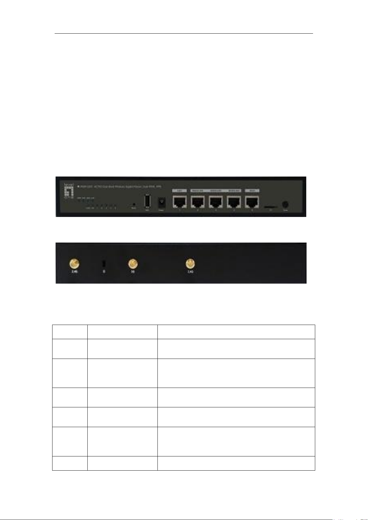
This section introduces the appearance of Progressive ™ 510W, and its front panel, back
panel is shown in Figure 2-1, Figure 2-2.
Figure 2-1 Diagram of front panel - Progressive WGR-2301
1. LED description
Figure 2-2 Diagram of rear panel - Progressive WGR-2301
http://www.level1.com Page 9
Page 10

Chapter 2 Hardware Installation
LED that corresponds to the port stays lit, and it will
flash if there is flow.
Note
The WPS feature is temporarily not supported by this software version, so the
corresponding status LED is not used.
Interface
Notes
LAN
Integrated with multiple Ethernet (100M) ports, LAN port is an RJ-45, and
supports adaptive positive and negative lines.
WAN
WAN port is an RJ-45 and supports adaptive positive and negative lines.
USB
3G Internet card interfaces.
Antenna
For transmitting and receiving wireless data.
2. Description of interfaces
Table 2-2 Description of interfaces
Table 2-1 LED description
3. Reset button
Reset button can be used to recover the device's factory settings when you forget the
administrator password. Method: In the process of charged operation, hold down the
Reset button for more than 5 seconds, and then release the button. The device will be
returned to its factory settings after operation, and automatically restart.
Note: The above operations will delete all the original device configurations; please
use it with care!
2.2 Precaution for installation
1. Make sure to install the workbench stably.
2. Do not place any heavy objects upon the device.
3. Make sure that the device is stored in a dry and ventilated area with proper heat
dissipation, and do not put it in a dirty and damp place.
4. Avoid exposing the device directly to the sunlight and keep it far away from heating
elements.
5. Mount the device away from the places where high power radio transmitters, radar
transmitters reside as far as possible.
http://www.level1.com Page 10
Page 11

Chapter 2 Hardware Installation
6. Please use the original power cord.
2.3 Preparing for installation
1. We have applied to local operators (ISP, such as China Telecom, China Unicom, etc.)
for broadband services.
2. Preparation of related devices:
1) Modem (This item is not required when connected directly to Ethernet).
2) Hub or switch or wireless devices.
3) The PC with Ethernet card and Internet Protocol (TCP/IP) installed.
4) Power socket.
3. Preparation of tools and cables: Network cables.
2.4 Hardware Installation
Before installing the device, make sure the broadband service is normal. If you cannot
access, please contact operators (ISP) to resolve the problem. After successfully
accessing to the network, follow these steps to install the device. The power plug must be
removed during installation.
Place the device on a stable work bench:
1. Place the device on a sufficiently large, stable and properly-grounded work bench with
its bottom up.
2. Remove the adhesive protective paper from the foot pad, and stick the 4 pads in the 4
round slots at the bottom of the casing respectively.
3. Flip over the device, and place it on the workbench stably.
http://www.level1.com Page 11
Page 12
Chapter 2 Hardware Installation
2.5 Hardware connection
1. Establish a LAN connection
Connect the LAN port of the router and a PC or a hub or a switch in LAN with a network
cable. Or after the device's wireless feature is enabled, connect wireless clients or other
wireless devices to the router over a wireless connection.
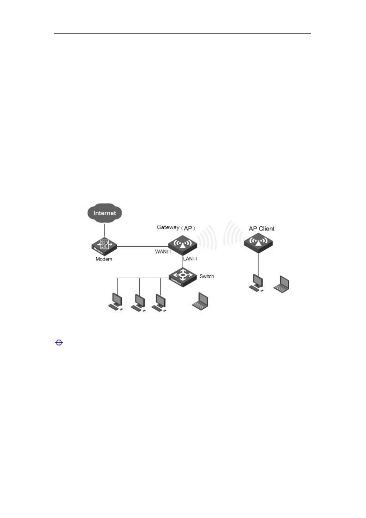
2. Establish a WAN connection
Connect the WAN port of the router to the Internet with a network cable, as shown in the
figure below.
3. Connect power source
Before connecting the power supply, make sure that both power supply and grounding are
normal.
Figure 2-3 Establish a LAN connection and a WAN connection
Tip: The above network connection diagram is for reference only. Please configure
the network architecture according to the actual situation and needs.
http://www.level1.com Page 12
Page 13

Chapter 3 Logging Device
Chapter 3. Logging to the device
This chapter describes how to configure the correct network settings for the network
computers, how to log on to the appliances and how to use shortcut icons to quickly link to
the HiPER website for product information and services.
3.1 Configuring the correct network settings
Before logging to the device through the WEB interface, you must correctly configure the
network computers in network settings.
First, connect your computer to the LAN port of the device, and then set the computer's IP
address.
The first step is to set the computer's TCP/IP. If it has been set correctly, skip this step.
The second step is to set the computer's IP address. You can use either of the following
methods:
1. Set the computer's IP address as one of the addresses from 192.168.1.2 -
192.168.1.254, the subnet mask is 255.255.255.0, and the default gateway is
192.168.1.1 (the LAN IP address of the device), and the DNS server is the address
provided by the local operator.
2. Set the computer's TCP/IP as "Obtain an IP address automatically". After setting, the
built-in DHCP server of the device will automatically assign IP addresses to
computers.
The third step is to use the Ping command on your computer to check whether it is
connected to the device. In Start ->Operation, type in cmd, and click <OK> to open the
command window. Type in ping 192.168.1.1.
The following lists two kinds of results of executing the Ping command in the Windows XP
environment:
If the screen is shown as follows, it indicates that the computer has been successfully and
a connection is established on the device.
http://www.level1.com Page 13
Page 14

Chapter 3 Logging Device
Pinging 192.168.1.1 with 32 bytes of data:
Reply from 192.168.1.1: bytes=32 time<1ms TTL=255
Reply from 192.168.1.1: bytes=32 time<1ms TTL=255
Reply from 192.168.1.1: bytes=32 time<1ms TTL=255
Reply from 192.168.1.1: bytes=32 time<1ms TTL=255
Ping statistics for 192.168.1.1:
Packets: Sent = 4, Received = 4, Lost = 0 (0% loss),
Approximate round trip times in milli-seconds:
Pinging 192.168.1.1 with 32 bytes of data:
Request timed out.
Request timed out.
Request timed out.
Request timed out.
Ping statistics for 192.168.1.1:
Packets: Sent = 4, Received = 0, Lost = 4 (100% loss),
If the screen is shown as follows, it indicates that the connection between the computer
and the device fails.
When connection fails, please check the following items:
1. Hardware connections: The LEDs that correspond to the LAN port on the device
panel and the PC network card LED must be on.
2. Configuring TCP/IP properties of the computer: If the LAN IP address of the device is
192.168.1.1, then the calculated IP address must be any one of the free addresses
from 192.168.1.2 - 192.168.1.254.
3.2 Logging to the device
When MS Windows, Macintosh, Unix or Linux operating systems are used on the PC, the
device can be configured through browsers (such as Internet Explorer or Firefox).
Open the browser, and type in the IP address of the device's LAN port in the address bar,
http://www.level1.com Page 14
Page 15
Chapter 3 Logging Device
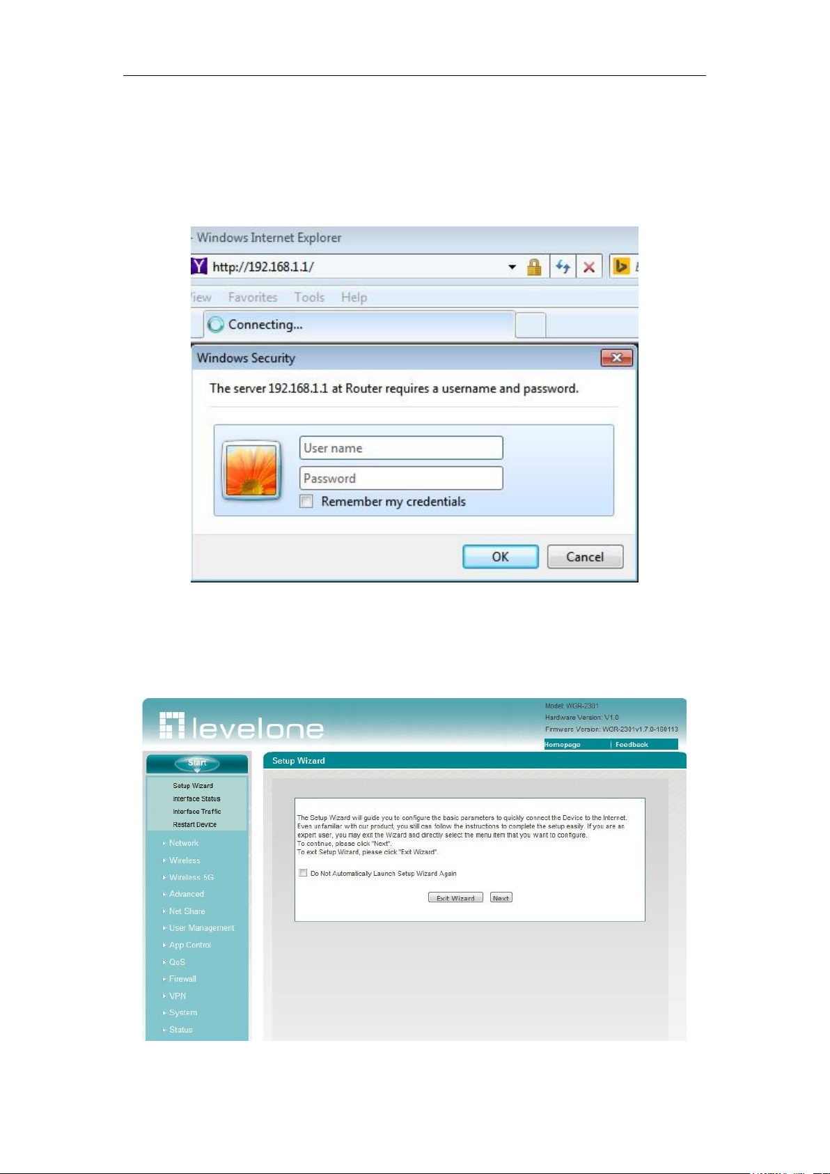
such as http://192.168.1.1. After the connection is established, you will see a login
interface as shown in Figure 3-1. In the first use, you should log in as a system
administrator, that is, enter your administrator username and password (the factory
defaults of username, password are admin and admin respectively, which are case
sensitive) on the login interface, and then click <OK>.
Figure 3-1 WEB login interface
If user name and password are correct, the browser will display the homepage of the WEB
management interface, as shown in Figure 3-2. The top-right corner of the page displays
device model, hardware version, software version and other information.
Figure 3-2 Homepage of the WEB interface
http://www.level1.com Page 15
Page 16

Chapter 3 Logging Device
Homepage description:
1. The top-right corner of the page displays device model, hardware version, software
version and three fast link icons. These 3 shortcut icons have the following functions:
1) Product Discussion– Link to the discussion forums of the HiPER official
website to participate in discussions about the product.
2) Knowledge Base– Link to the knowledge base of HiPER official website for
searching related technical information.
3) Booking Service– Link to the booking service page of HiPER official website, for
advance reservation of the customer service in a certain working period.
2. This page displays the main menu bar on the left.
3. The main operating page is located on the right of the page, in which you can
configure various functions of the device, view the related configuration information
and status information, etc.
4. If this is the first time for you to log in the device, the main operation page will be
linked directly to the configuration wizard page. The next chapter describes how to
configure the basic parameters required for the normal running of the device in the
Start -> Configuration wizard page.
http://www.level1.com Page 16
Page 17
Chapter 4 Configuration Wizard
Chapter 4. Configuration Wizard
By reading this chapter, you can understand the basic network parameters required for
the device to access to the Internet, and these parameters are configured to connect the
device to the Internet. Before configuring "Internet Line" in the Configuration Wizard, you
should properly configure the network settings of the network computer. For specific
methods, see Chapter 3 Logging in the Device.
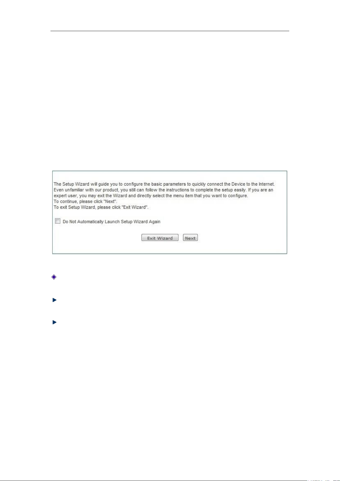
If this is the first time for you to log in the device, a configuration wizard homepage
appears directly in the main operating page. As shown in Figure 4-1:
Figure 4-1 Homepage of configuration wizard
In logging next time, the wizard will no longer automatically pop up: When checking it,
you can go directly to the System Status page in logging next time.
Exit the wizard: Exits the Configuration Wizard and returns to the System Status
page.
Next step: Enter the Selection of device access mode page.
4.1 Configuration of WAN1 port
Access modes provided by WAN1 port include: dynamic IP access, fixed IP access,
PPPoE access.
http://www.level1.com Page 17
Page 18
Chapter 4 Configuration Wizard
4.1.1 Dynamic IP access
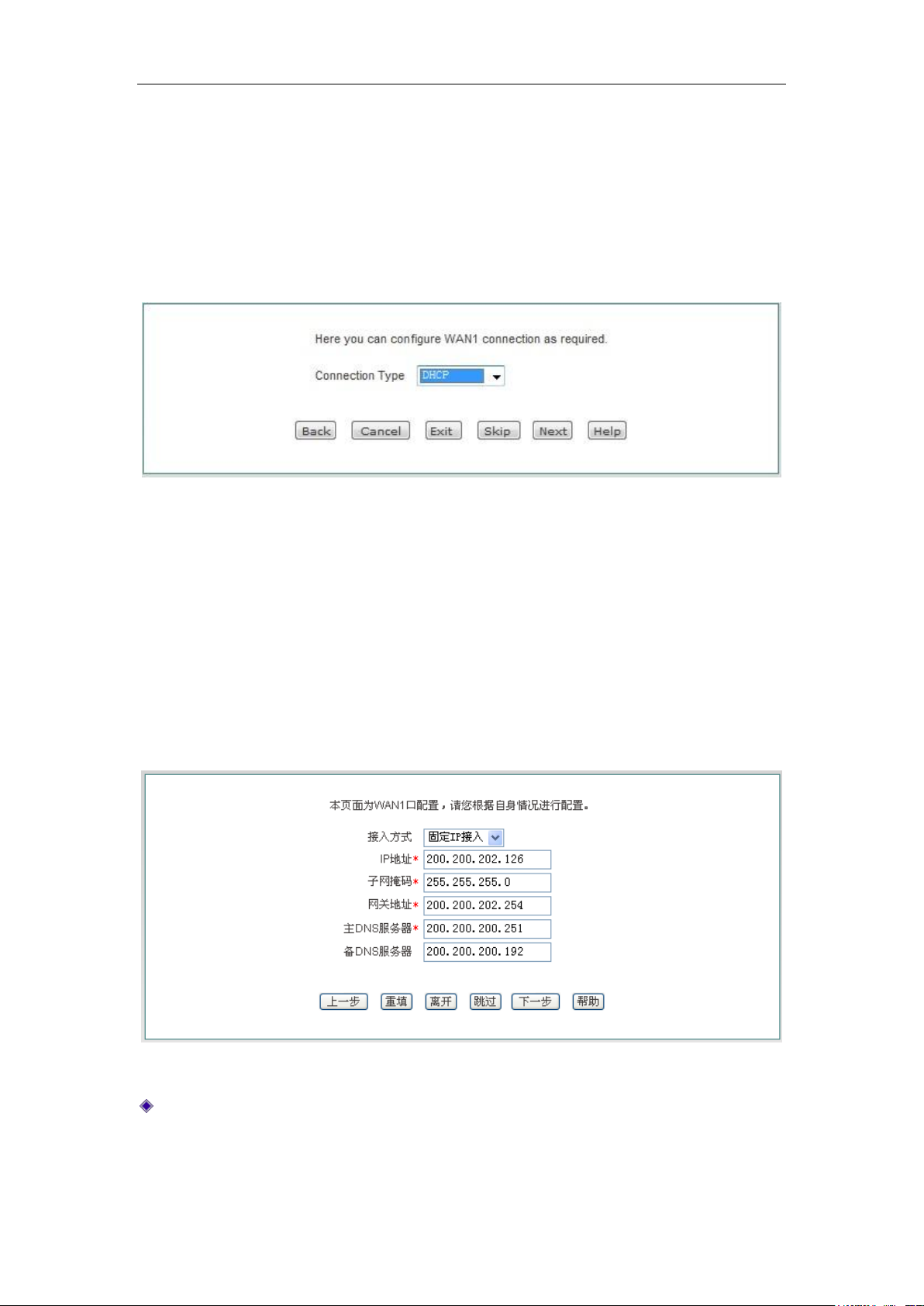
The default WAN1 access is dynamic IP access, as shown in Figure 4-3. If your Internet
access mode is dynamic IP access, please click <Next>, to complete the configuration of
the WAN1 port.
Figure 4-2 Configuration Wizard - Dynamic IP access
4.1.2 Static IP access
If your Internet access mode is Static IP access, please select "Fixed IP access" in the
drop-down list box of Figure 4-4, and fill in the related parameters, and enter into the next
page, to complete the configuration of WAN1.
Figure 4-3 Configuration Wizard - Static IP access
IP address, subnet mask, gateway address, primary DNS server, secondary DNS
server: Fill in the WAN IP address, subnet mask, gateway address and DNS server
address that ISP (Such as China Telecom) offers you.
http://www.level1.com Page 18
Page 19
Chapter 4 Configuration Wizard
4.1.3 PPPoE access
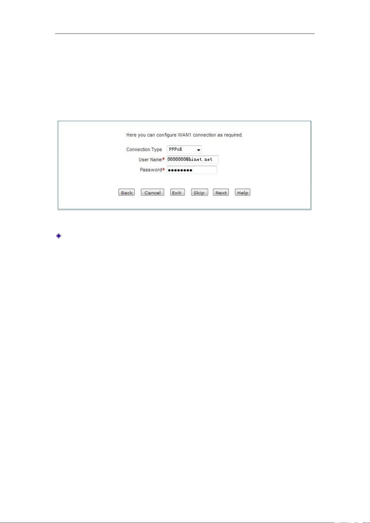
If your Internet access mode is PPPoE access, please select "PPPoE access" in the
drop-down list box of Figure 4-5 , and fill in the corresponding user name and password,
and then click <Next> to enter into the next page to complete the configuration of WAN1.
Figure 4-4 Configuration wizard - PPPoE access
User name, password: Type in the user name, password provided by the ISP. If you
have any questions, please ask your ISP.
http://www.level1.com Page 19
Page 20
Chapter 5 Start Menu
Chapter 5. Start menu
Start menu is located on the top of the Level 1 menu bar of the WEB interface, providing
the interface for 4 common pages, including: configuration wizard, running status, port
flow, device reboot. In the Start menu, you can quickly configure the basic parameters
required by the device in working properly, view the information about the interfaces, and
view the statistics data of the devices' real-time traffics.
5.1 Setup Wizard
The Start-> Setup wizard pages can help you to quickly configure the basic parameters
required by some devices in working normally. For details, see Chapter 4 Configuration
Wizard.
5.2 Interface status
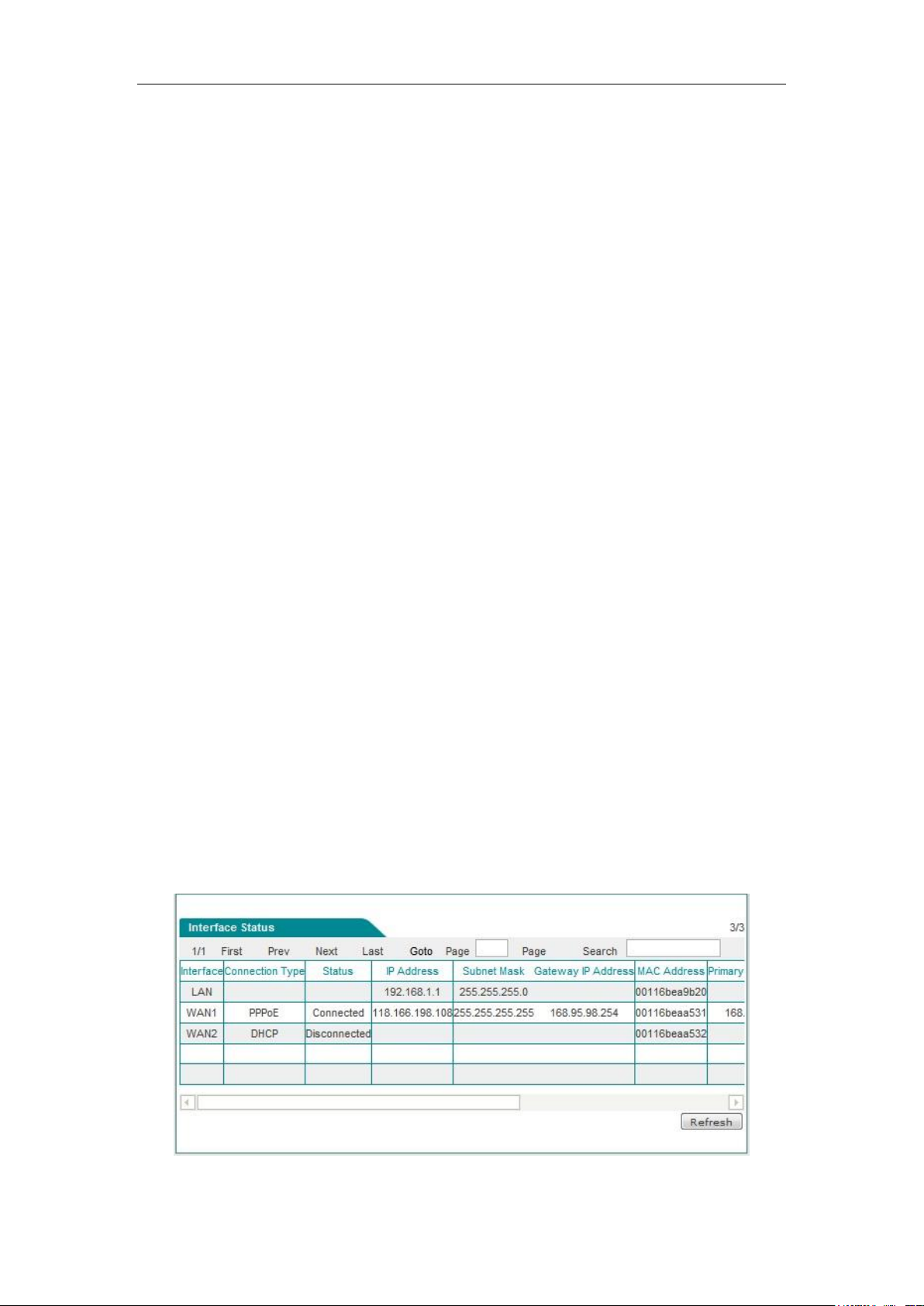
This section describes the Start-> Interface status page, in which you can view the
information about the device's interfaces. As shown in the interface in Figure 5-1, the
connection type, connection status, IP address and other information about the interfaces
can be viewed.
Figure 5-1 Interface status
http://www.level1.com Page 20
Page 21
Chapter 5 Start Menu
5.3 Interface Traffic
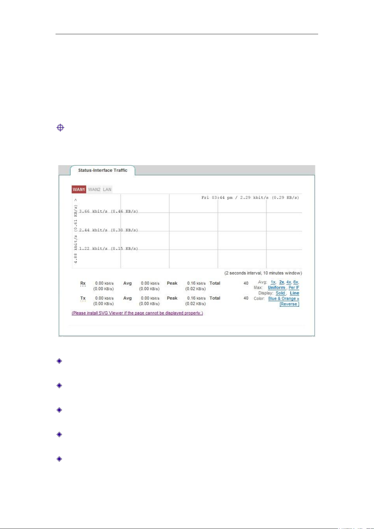
This section describes the Start-> Interface Traffic page, as shown in Figure 5-2. You
can view the average, maximum, sum and the current real-time rate for the relevant ports
to receive and send data, and provide different units (Kbit/s and KB/s) for them.
Tip:
If this page fails to display properly, please click the hyperlink "If it cannot display properly,
please install a svgviewer" to have the svgviewer plug-in installed.
Figure 5-2 Interface Traffic
WAN1: WAN port of the device, click on the tab to view the dynamic figure of
receiving, sending traffic.
APClient: The wireless client of the device, click on the tab to view the dynamic figure
of receiving, sending traffic.
LAN: LAN port of the device, click on the tab to view the dynamic figure of receiving,
sending traffic.
Timeline: The x-coordinate in the flow chart. You can click on the timeline options (1x,
2x, 4x, 6x in the figure) in the figure to determine the display effect.
Flowline: The y-coordinate in the flow chart. You can choose the display effects as
needed (standardization, maximization as shown in the figure).
http://www.level1.com Page 21
Page 22

Chapter 5 Start Menu
Display: Provides two display effect options, solid effect and hollow effect.
Color: It can be selected for display according to needs and preferences, such as red,
blue, orange, etc.
Flip: Click the Flip button, and the colors can swap to receive and send data.
5.4 Restart device
If you need to restart the device, just enter into the Start-> Restart device page to click
<Restart>.
Figure 5-3 Restart device
Tip: Upon restarting, all users will be disconnected from the device.
http://www.level1.com Page 22
Page 23
Chapter 6 Network parameters
Chapter 6. Network parameters
In the network parameter menu, you can configure the basic network parameters for the
device, including WAN/LAN configuration, line combination, DHCP server, DDNS
configuration and UPnP.
6.1 Configuration of WAN port
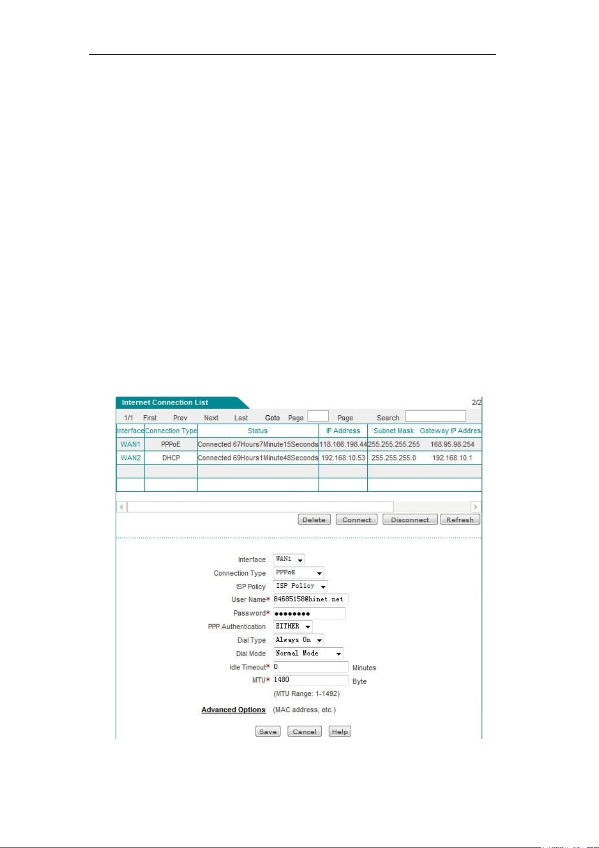
This section describes the Network parameters ->WAN configuration page. In this page,
you can configure not only the line information, modify or delete the configured lines
according to the actual needs, but also view the connection status of lines.
After completing the configuration of Internet line in Configuration Wizard, you can view
the connection and configuration of the line in this page, or modify the configuration as
needed.
Figure 6-1 Configuration of WAN port
http://www.level1.com Page 23
Page 24
Chapter 6 Network parameters
6.1.1 WAN1 access
1. Dynamic IP access
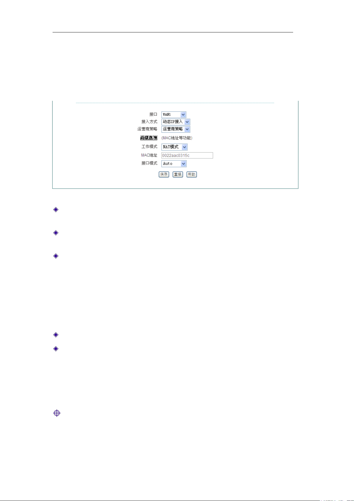
Figure 6-2 Dynamic IP access
Access mode: Selects the corresponding access mode, and "Dynamic IP access" is
selected here.
Operator policy: Selects the operator of the interface, with the options as follows:
Operator policy, China Telecom, China Unicom and China Mobile respectively.
Working mode: Options include NAT and routing mode.
NAT mode: Network address translation. The router working in this mode can
convert the IP address of the Intranet (LAN side) to that of the external network
(WAN side). The router works in this mode by default.
Routing mode: The router working in this mode will not NAT-convert the IP
address for the Intranet (LAN side) to access to the external network (WAN side),
and directly looks up the routing table for forwarding.
MAC address: The MAC address of the corresponding interfaces.
Interface mode: Sets the duplex mode and rate for interfaces. Options are: Auto
(adaptive), 10M-FD (10M full duplex), 10M-HD (10M half duplex), 100M-FD full
duplex (100M), 100M-HD (100M half duplex). The default is Auto, which is usually not
required to be modified, and if there is any compatibility issue, or the device used
does not support auto negotiation function, then the type of Ethernet negotiation can
be set up here.
Tip:
1. When configuring the line, users can select the appropriate operator through
"Operator policy", and the system will generate a corresponding route based on the
user's choice, you can easily achieve the goal that Telecom traffic flows on the
http://www.level1.com Page 24
Page 25
Chapter 6 Network parameters
Telecom routes while Unicom traffic flows on the Unicom routes.
2. Generally, it is not recommended to modify the MAC address of interfaces. However,
in some cases, the operator binds the MAC of the device, which results in the failure
of the new network device to dial up successfully, and at this time, the MAC address
of the device needs to be modified as that of the original network device.
2. PPPoE access
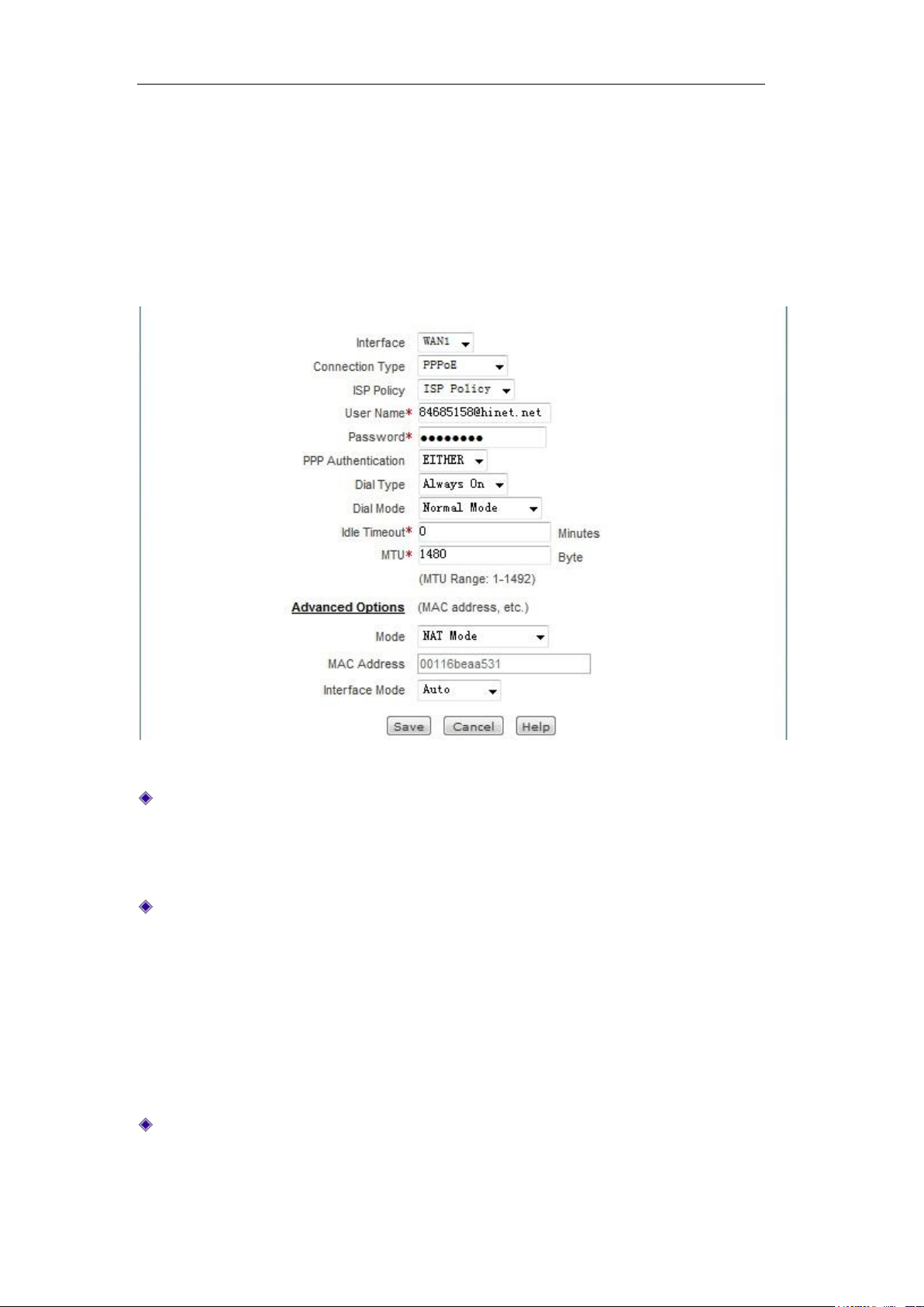
Figure 6-3 PPPoE access
Password authentication mode: The mode that operators verify user names,
passwords. Options include: NONE (not to be verified), PAP, CHAP, and EITHER
(automatically negotiate with the peer device on the mode of password
authentication).
Dialing type: The options include auto dialing, dialing on demand, manual dialing.
Auto dialing: The device automatically dials up when it is powered on or the
previous dial-up disconnection occurs.
Dialing on demand: The device will dial up automatically when there is Internet
traffic in the intranet.
Manual dialing: Manual dialing and hanging up. Click <Dial>, and <Hang up> on
the bottom right of the list to implement manual dialing.
Dialing mode: If the dial-up is not successful, try using other modes on the premise of
using the correct user name and password.
http://www.level1.com Page 25
Page 26
Chapter 6 Network parameters
Idle time: The time length after there is no Internet traffic of access and before
automatic disconnection. 0 means no automatic disconnection.
MTU: Maximum transmission unit, 1480 bytes by default. The device will
automatically negotiate with the peer device in PPPoE dialup. Do not modify it unless
in special applications.
For the working mode in the advanced options, MAC address, interface mode, please
refer to the configuration of dynamic access.
3. Static IP access
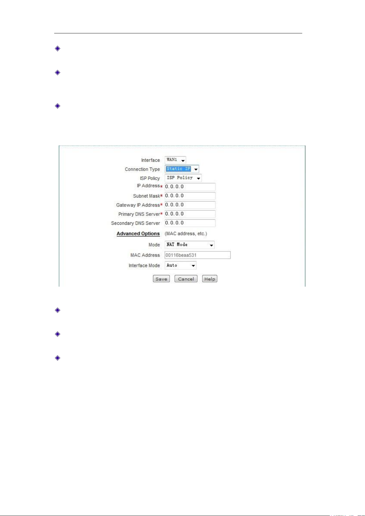
Figure 6-4 Static IP access
IP address, subnet mask, gateway address: Static IP address, subnet mask and
gateway address provided by the operator.
Primary, secondary DNS server: The DNS server address the operator provides to
you.
For the working mode in the advanced options, MAC address, interface mode, please
refer to the configuration of dynamic access.
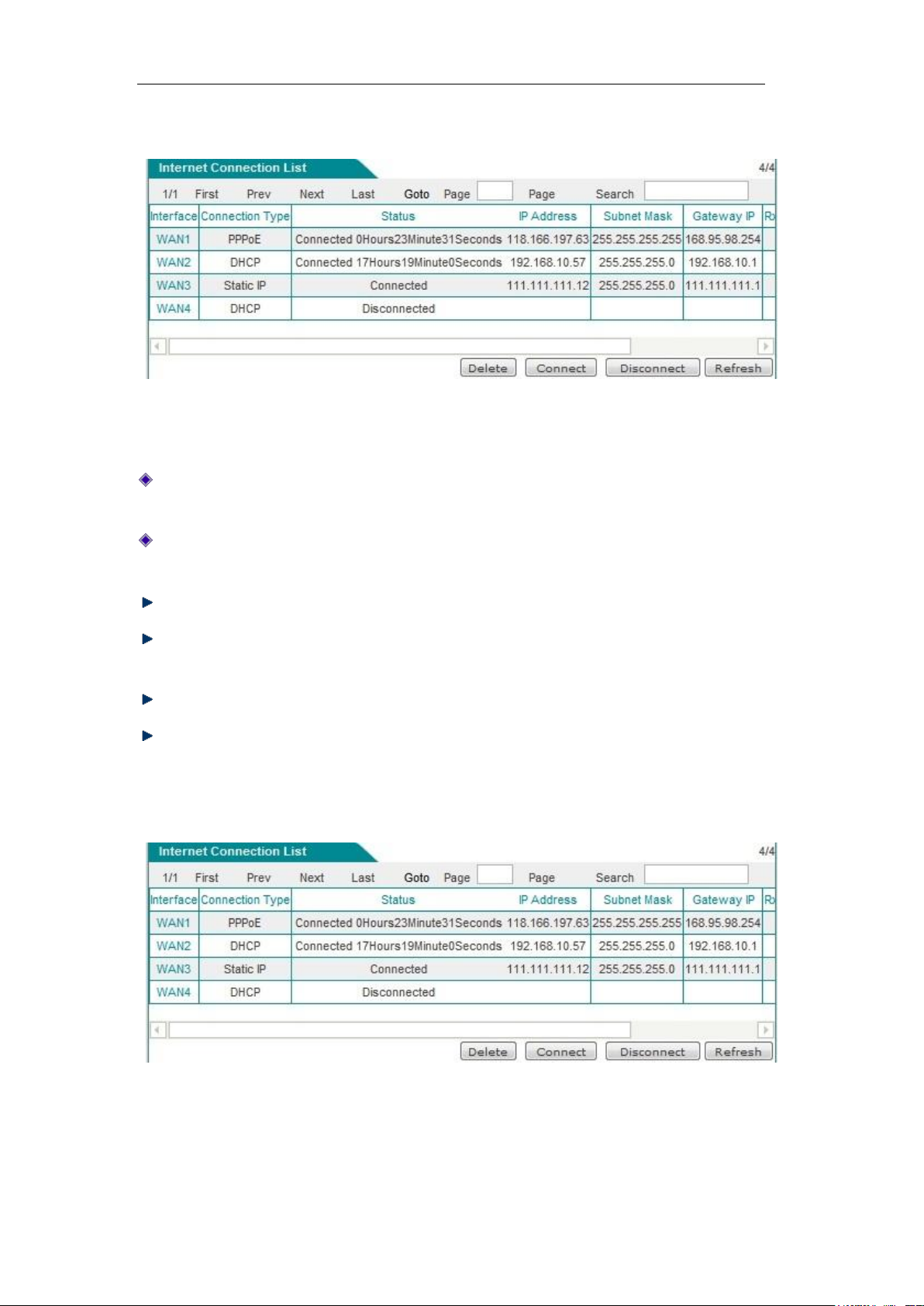
6.1.2 List of line connection information
The following describes the list of line connection information when the connection types
are dynamic IP access, Static IP access, PPPoE access,
http://www.level1.com Page 26
Page 27
Chapter 6 Network parameters
1. Dynamic IP access
Figure 6-5 List of line connection information - Dynamic IP access
As shown in the above figure, APClient port is a dynamic IP access.
Connection type: In the case of "Connected", it shows the time length of the
connection.
Downstream rate, upstream rate: The downlink/uplink average rate of the current line
at the time interval of two times of list refreshing. The unit is KB/s.
Delete: Deletes the appropriate line.
Update: Click <Refresh>, and the system automatically completes the process of
releasing the IP address, and then obtaining an IP address again.
Release: Click <Release>, to release the currently obtained dynamic IP address.
Refresh: Click <Refresh>, to display the up-to-date information of line connection
information list.
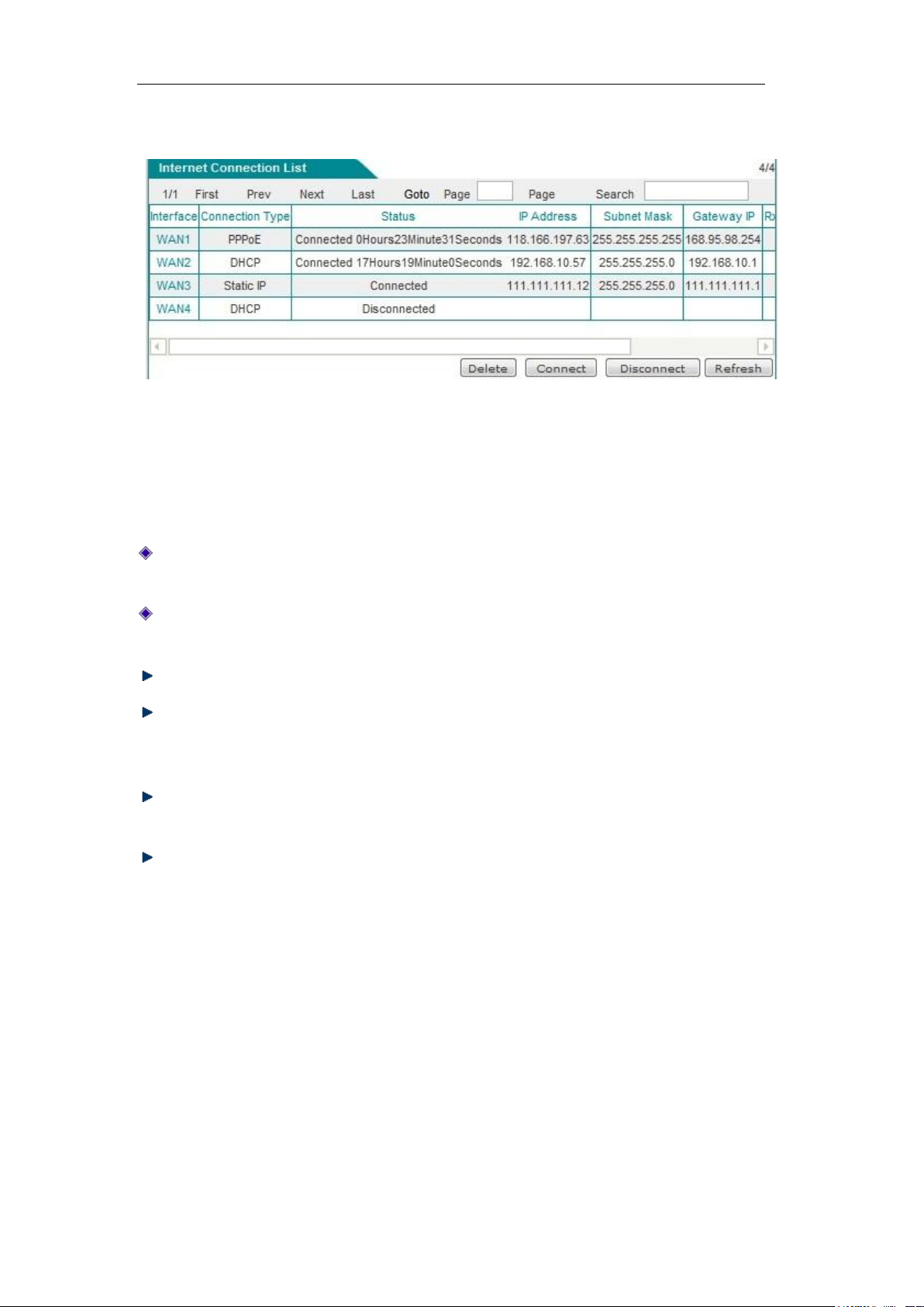
2. Static IP access
Figure 6-6 List of line connection information - Static IP access
As shown in the above figure, WAN3 is Static IP access. Its IP address, subnet mask,
gateway address are the parameters for configuring the WAN port.
http://www.level1.com Page 27
Page 28
Chapter 6 Network parameters
3. PPPoE access
Figure 6-7 List of line connection information - PPPoE access
If a line is a PPPoE dialup one, then click on the interface, the "Dial-up" and "Hang-up" will
appear below the "Line connection information list", as shown in the figure above, the
WAN1 port is PPPoE access, click on "WAN1", and four buttons are displayed on the
lower right part of the line connection information list.
Connection status: As being in "Connected", the time that the line remains the
connection will be displayed.
IP address, subnet mask, gateway address: IP address, subnet mask, and gateway
address assigned by the connected device to the interface.
Delete: Deletes the appropriate line.
Dial-up: Click <Dial>, to establish the PPPoE access, 3G access line unestablished
or disconnected (When the PPPoE connection dial-up type is set to "Manual dial-up",
and the PPPoE dial-up is to be completed here).
Hang up: Click <Hang-up>, to hang up the PPPoE dial-up line or 3G access line that
has been established.
Refresh: Click <Refresh>, to display the up-to-date information of line connection
information list.
6.2 Line combination
This section describes the Network parameter -> Line combination page.
In the line combination configuration, you can quickly configure line combination modes,
and other related parameters, and specify the detection interval, detection number,
detection target IP address and bandwidth of the lines.
http://www.level1.com Page 28
Page 29

Chapter 6 Network parameters
6.2.1 Description of line combination function
1. Line detection mechanism
Regardless of line combination modes, make sure that the network is not interrupted
when the line fails, which require that the device must be able to monitor line status in real
time. To this end, we designed a flexible automatic detection mechanism, and provide a
variety of line detection methods for users to choose, in order to meet the practical
application needs.
To facilitate understanding, several related parameters are introduced first.
Detection interval: The time interval of sending inspection packets. One inspection packet
is sent per time, and the default value is 0 seconds. In particular, when the value is 0, it
means not to make line detection.
Detection times: The number of inspection packets sent within each detection cycle.
Destination IP address: The object of detection. The device will send inspection packets to
the pre-designated target to detect if the line is normal.
The following is an introduction of the device's line detection mechanism in two cases: line
normal and line failure.
When a line fails, the detection mechanism is described as follows: The device will send
an inspection packet to the detection target of the line at the specified detection interval. If
all the inspection packets sent have no response within a detection cycle, this line will be
deemed to be failed, and it will be shielded immediately. For example, if the 3 inspection
packets that are sent have no response within a detection cycle, the line is deemed to be
failed by default.
When a line is normal, the detection mechanism is described as follows: Similarly, the
device will send an inspection packet to the detection target of the line at the specified
detection interval. If half of the inspection packets or above sent have response within a
detection cycle, this line will be deemed to be normal, and it will be restored. For example,
if there are 2 inspection packets that have responded within a detection cycle by default,
the line is deemed to be restored by default.
The device allows users to specify Internet lines for some hosts in the Intranet in advance,
which is realized by setting the "Internal starting IP address" and "Internal end IP address"
of the line, and the hosts whose IP addresses are within two address ranges will give
priority to the use of the specified line. For the hosts with the specified Internet line, they
can only access to the Internet through that line when the specified line is normal.
However, when the specified line fails, they will use other normal lines for Internet access.
Tip: Line detection is not enabled, then the "Detection interval" should be set to "0"
second.
http://www.level1.com Page 29
Page 30

Chapter 6 Network parameters
2. Line combination mode
The device provides 2 line groups: "Main line" group and "Backup line" group. For
convenience's sake, the lines in the "main line" group are collectively known as main line,
and the lines in the "backup line" group are collectively known as backup line. All lines are
main lines by default. Users can divide some lines into the "Backup line" group as needed.
The device provides two line combination modes, "All line load balancing" and "Partial line
load balancing while the other backed up".
In the "All line load balancing" mode, all lines are used as main lines. Working principles
are as follows:
1. When all lines are normal, the Intranet hosts can use all lines for Internet access
simultaneously.
2. If a line fails, it should be shielded immediately, and the flow originally passing
through the line will be allocated to the other lines.
3. Once the fault line is restored to normal, the device will enable this line automatically,
and the flow is automatically redistributed.
In the "Partial line load balancing while the others backed up" mode, part of the lines are
used as main lines, the other part of the lines is used as backup lines. Working principles
are as follows:
1. As long as the main line is normal, the Intranet hosts use main lines for Internet
access.
2. If the main line fails, it will automatically switch to using the backup line for Internet
access.
3. Once the fault lines are restored to normal once, they will be immediately switched
back to the main line.
Tip: When a line is interrupted for line switching, some user applications (such as part
of network games) may be unexpectedly interrupted. This is determined by the TCP
session property.
6.2.2 Global configuration of line combination
In these two line combination modes, "All line load balancing" and "Partial line load
balancing while the others backed up", the interface of global setting is different; therefore,
their universal setting parameters are described below respectively.
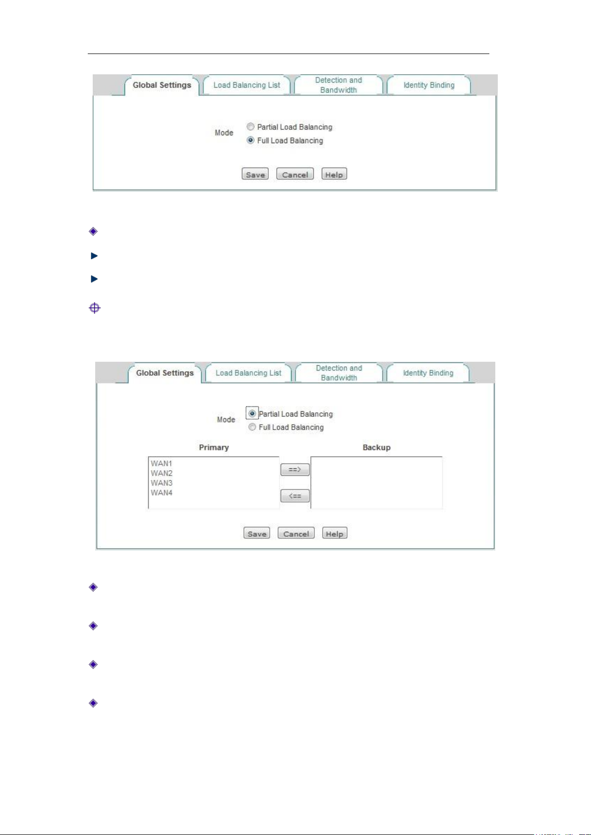
1. Full Load Balancing
http://www.level1.com Page 30
Page 31
Chapter 6 Network parameters
Figure 6-8 Full Load Balancing
Line load balancing mode: "All line load balancing" is selected here.
Save: The line combination configuration parameters take effect.
Refill: Restores to the configuration parameters before modification.
Tip: Line combination mode is "All line load balancing" by default.
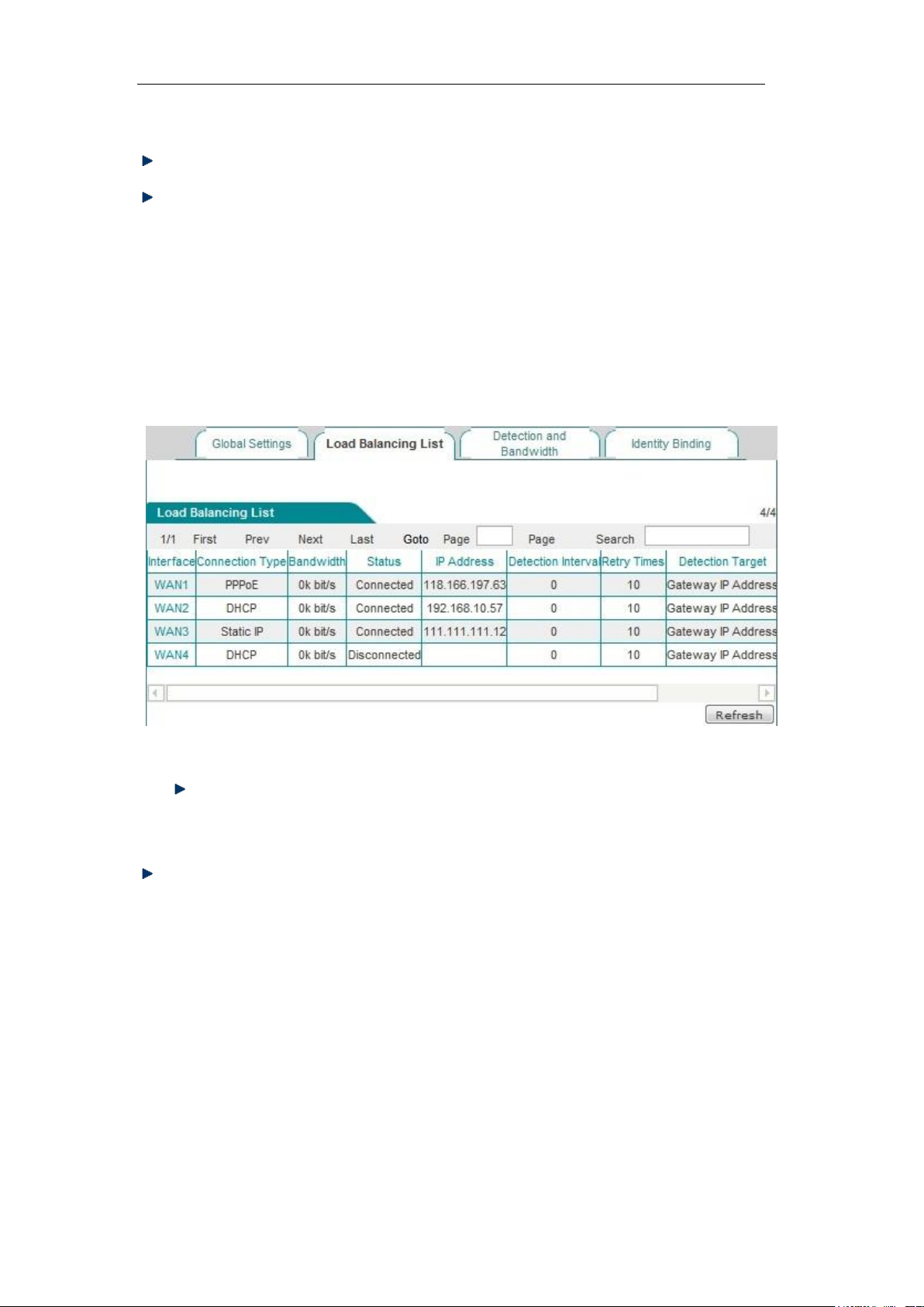
2. Partial Load Balancing
Figure 6-9 Partial Load Balancing
Line combination mode: "Partial line load balancing while the others backed up" is
selected here.
Main line: The list box represents the "Main line" group, and all the lines in the list box
are used as the main lines.
Main line: The list box represents the "Backup line" group, and all the lines in the list
box are used as the backup lines.
==> (Right arrow), <== (Left arrow): Select one (or more) line in the "Main line" list
box first, and then click on "==>", and the selected lines are immediately moved to the
"Backup line" list box. Similarly, select one (or more) line in the "Backup line" list box
first, and then click on "<==", and the selected lines are immediately moved to the
http://www.level1.com Page 31
Page 32
Chapter 6 Network parameters
"Main line" list box.
Save: The line combination configuration parameters take effect.
Refill: Restores to the configuration parameters before modification.
6.2.3 Load Balancing List
In the Network parameter -> Line combination -> Line combination status
information page, you can view, configure the information of configuration line.
Figure 6-10 Load Balancing List
Edit the line combination status information: Click on the interface of the line or
the "Edit" hyperlink corresponding to the line, to skip to the relevant page for
change, as shown in Figure 6-11.
Refresh: Click <Refresh>, to get the latest status information of line combination.
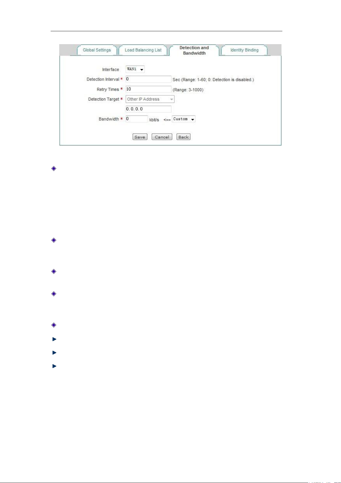
6.2.4 Detection and bandwidth configuration
After configuring the line combination function, you also need to configure the detection
mechanism of the lines, and the configuration methods are as follows.
Enter the Network parameters -> Line combination -> Detection and bandwidth
configuration page, or enter the Line combination status information list and click a
line interface or edit the icon, and enter the Detection and bandwidth distribution page.
http://www.level1.com Page 32
Page 33
Chapter 6 Network parameters
Figure 6-11 Line combination configuration
Interface: Selects access modes (WLAN, 3G, APClient)
WAN1 configuration: Configure WAN1 to provide access to intranet users.
3G client configuration: The device provides access to intranet users as a 3G
client.
Wireless client configuration: The device provides access to intranet users as a
wireless client.
Detection interval: The time interval for sending inspection packets, Unit: seconds,
when you enable line detection, the value range is 1~60 (the value is 0, which means
not to enable the line detection).
Detection times: The number of inspection packets sent within the detection cycle
(one detection packet is sent per time), which is 10 times by default.
Detection target: The destination address to be detected, which is the gateway IP
address by default; if the gateway disallows PING, select a different IP address as the
destination IP address of the PING detection.
Bandwidth: Sets the bandwidth that ISP provides to the current line.
Save: The above configuration parameters take effect.
Refill: Restores to the configuration parameters before modification.
Return: Returns to the line combination state information page.
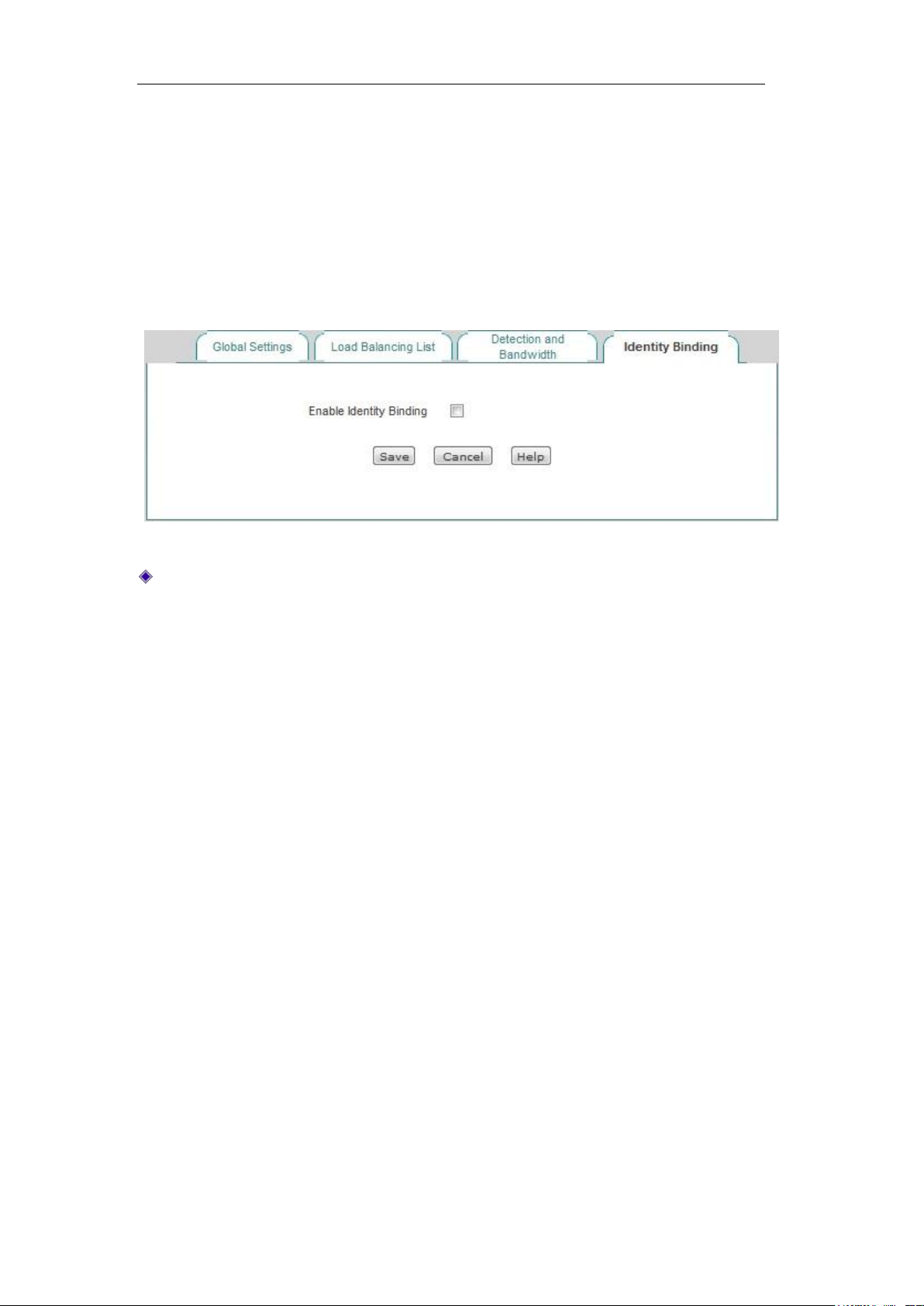
6.2.5 Identity binding
When the device has multiple WAN ports, you can enter the Network parameters -> Line
http://www.level1.com Page 33
Page 34
Chapter 6 Network parameters
configuration -> Identity binding page to enable the identity binding function.
In the case of multi-line session load balancing, NAT sessions in the same application
may be distributed in different lines, which will cause such applications as online bank, QQ,
etc. not to work properly due to change of identity. The identity binding function can
address this issue by binding the sessions in the same application from the same user on
a line. For example, when a user in the Intranet logs in the online bank, if the first session
is assigned to WAN2 port connection line, all the online banking sessions of this user will
go out from the WAN2 port until the user logs out.
Figure 6-12 Enabling identity binding
Enable identity binding: Enables/disables the identity binding function. If multiple lines
are configured, please enable the device's identity binding function to make normal
use of such apps as QQ, online bank.
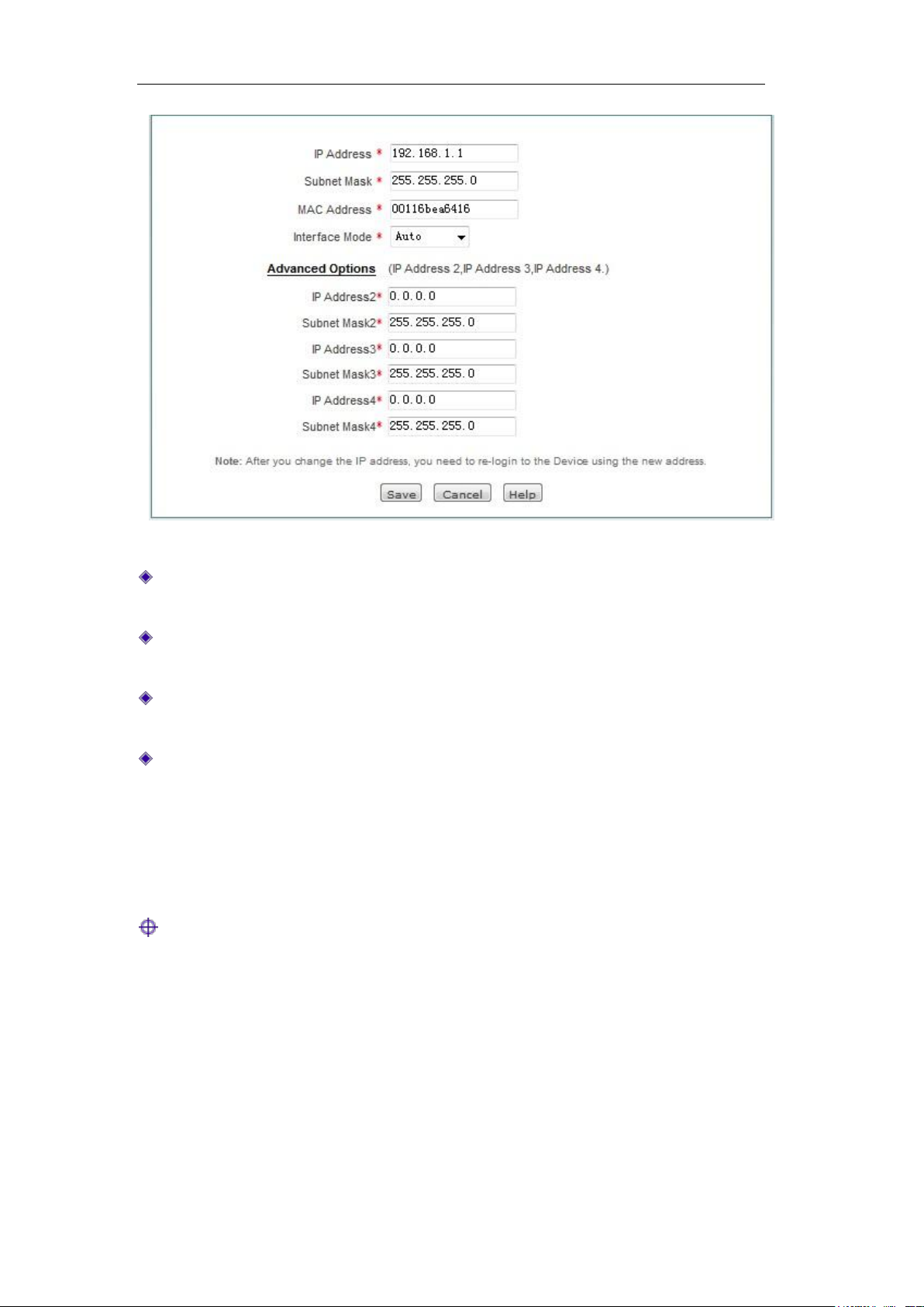
6.3 Configuration of LAN port
The device's LAN ports can be configured with 4 IP addresses, and the first default IP
address of the LAN port is 192.168.1.1. If you need to change the LAN IP address in order
to adapt to the existing network, enter the Network parameters > LAN port
configuration page for configuration.
http://www.level1.com Page 34
Page 35
Chapter 6 Network parameters
Figure 6-13 Configuration of LAN port
IP address: Sets the LAN IP addresses, and the first IP address is 192.168.1.1 by
default, while the other three IP addresses are 0.0.0.0 by default.
Subnet mask: Sets the subnet mask of the corresponding IP address, which is
255.255.255.0 by default.
MAC address: The MAC address of the LAN port. It is suggested not to modify the
MAC address of the LAN port freely.
Interface mode: Sets the duplex mode and rate for interfaces. Options are: Auto
(adaptive), 10M-FD (10M full duplex), 10M-HD (10M half duplex), 100M-FD full
duplex (100M), 100M-HD (100M half duplex). The default is Auto, which is usually not
required to be modified, and if there is any compatibility issue, or the device used
does not support auto negotiation function, then the type of Ethernet negotiation can
be set up here.
Tip:
After modifying the LAN IP address, you must use a new IP address to log into the device,
and the IP for logging into the host must be on the same network segment.
6.4 DHCP server
This section mainly introduces the Network parameters -> DHCP server page, including
http://www.level1.com Page 35
Page 36
Chapter 6 Network parameters
DHCP server settings, static DHCP and DHCP automatic binding and DHCP client list.
6.4.1 DHCP server configuration
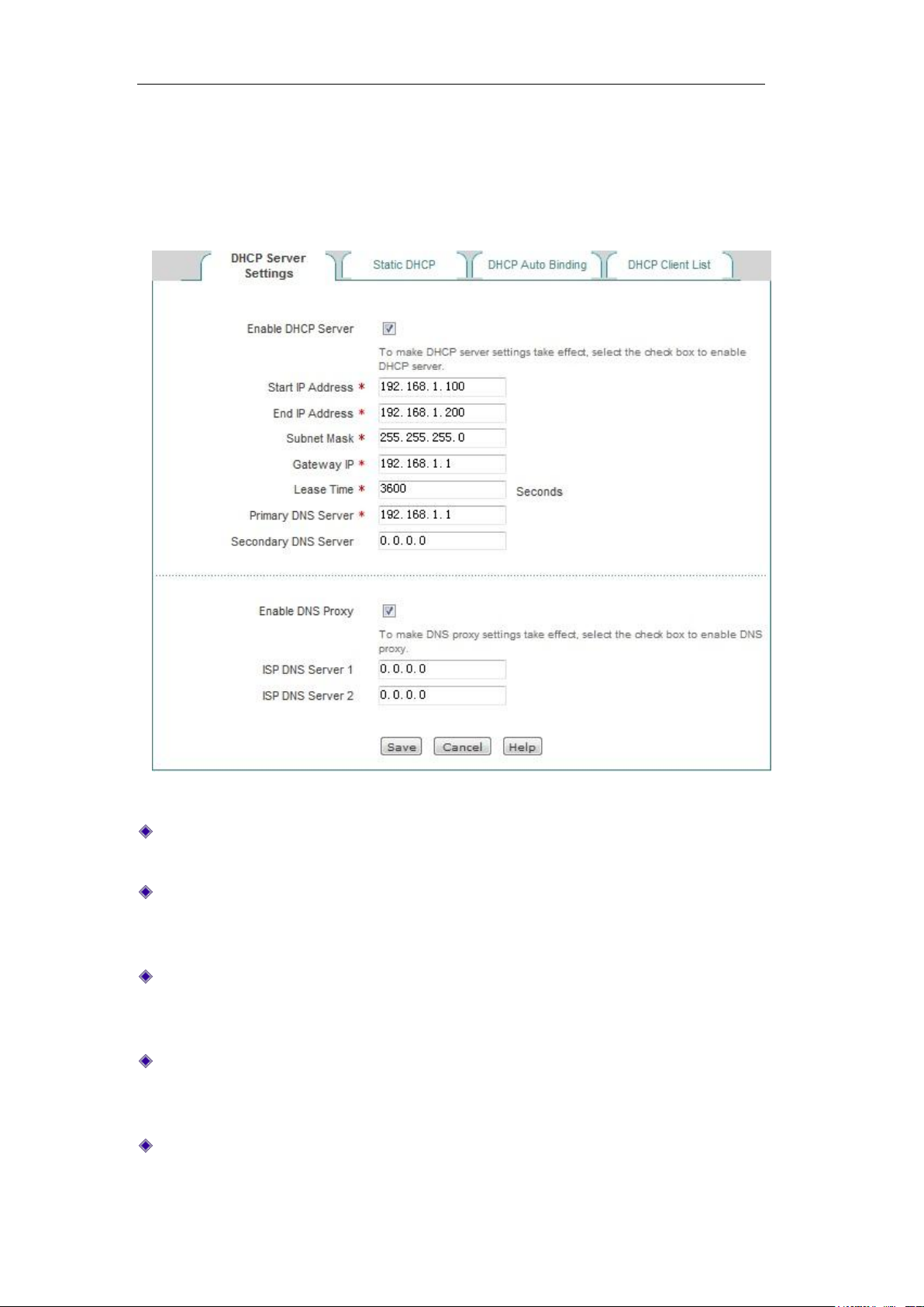
Figure 6-14 Configuring the DHCP service
Enable DHCP server: Used to disable or enable the device's DHCP server function.
Selecting it means allow.
Start and end IP address: The IP address fields the DHCP server assigns to the
network computer automatically (which should be on the same network segment as
the IP address of the device LAN port).
Subnet mask: The subnet mask automatically assigned by the DHCP server to the
network computer (which should be consistent with that of the LAN port of the
device).
Gateway address: The gateway IP address the DHCP server automatically assigns to
the network computer (which should be consistent with the LAN IP address of the
device).
Leasing time: The leasing time for the network computers to obtain the IP address
assigned by the device (Unit: Seconds).
http://www.level1.com Page 36
Page 37

Chapter 6 Network parameters
Primary DNS server: The IP address of the primary DNS server automatically
assigned by the DHCP server to the network computers.
Secondary DNS server: The IP address of the secondary DNS server assigned by
the DHCP server to the network computers automatically.
Enable DNS proxy: Selecting it means enabled. The DNS proxy function of the device
will not take effect unless enabled. After enabling this function, the gateway address
is assigned to a client as primary, secondary DNS servers.
Operator DNS servers 1, 2: The IP address of operator DNS server.
Tip:
1. If the device's DHCP server function is to be used, network computer's TCP/IP
protocol can be set to "obtain an IP address automatically".
2. If what's originally used by the user is a proxy server software (such as Wingate), and
the PC's DNS server is set as the IP address of the proxy server, then the LAN IP
address of the device only needs to be set to the same IP address, so that the user
can switch to using the device's DNS proxy function without having to change the PC
setting after the device enables the DNS proxy function.
6.4.2 Static DHCP
This section describes the static DHCP list and the way to configure a static DHCP.
Using the DHCP service to automatically configure TCP/IP properties for the network
computers is very convenient, but it can cause a computer to be assigned with different IP
address at different times. And some Intranet computers may need a fixed IP address, in
this case, the static DHCP function is required, to bind the computer's MAC address with
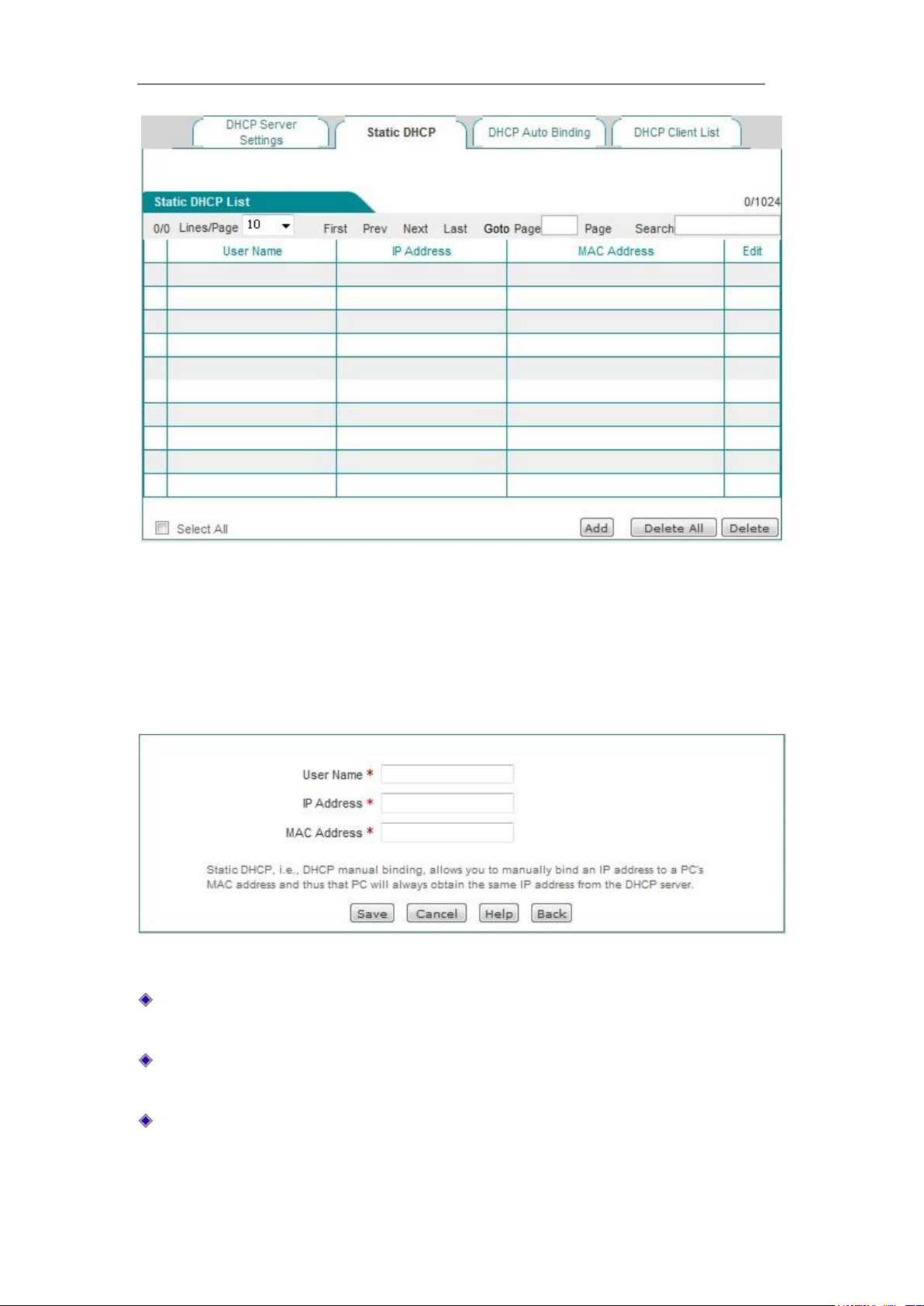
an IP address, as shown in Figure 6-15. When a computer having this MAC address
requests the address from the DHCP server (device) , the device will find a corresponding
fixed IP address based on its MAC address and assign it to the computer.
1. Static DHCP list
http://www.level1.com Page 37
Page 38
Chapter 6 Network parameters
Figure 6-15 Static DHCP list
2. Static DHCP configuration
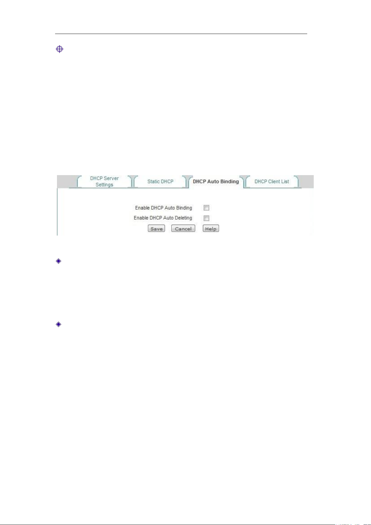
Click <Add new entry> in the page as shown in Figure 6-15, to enter into the Static DHCP
configuration page as shown in the figure below. Below is a description of the meaning of
the parameters for configuring static DHCP.
Figure 6-16 Static DHCP configuration
User name: Configures the user name of the computer bound by this DHCP (custom,
no repeat is allowed).
IP address: The reserved IP address, which must be the valid IP address within the
address range specified by the DHCP server.
MAC address: The MAC address of the computer to use this reserved IP address in a
fixed way.
http://www.level1.com Page 38
Page 39
Chapter 6 Network parameters
Tip:
1. After the setting is successful, the device will assign the preset IP address for the
specified computer in a fixed way.
2. The assigned IP addresses must be within the range provided by the DHCP server.
6.4.3 DHCP auto binding
Below is the description of DHCP automatic binding function.
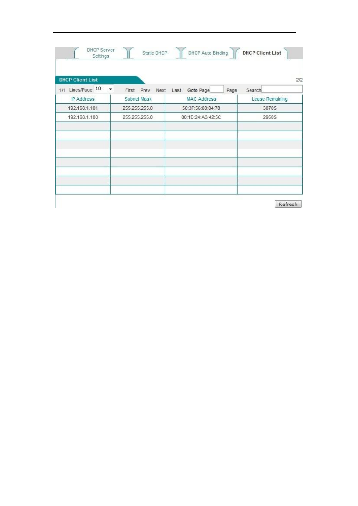
Figure 6-17 DHCP auto binding
Enable DHCP automatic binding: When DHCP automatic binding is enabled, the
device will scan the Intranet, and bind IP/MAC of intranet users who obtain an IP
address dynamically, and the device will bind any one IP address it assigns
subsequently with the MAC address of the client. Enabling this function can protect
against network ARP spoofing. If it is not enabled, no automatic binding operation is
to be done.
Enable DHCP automatic deletion: When DHCP automatic deletion is enabled, it
means that the device will automatically delete the IP/MAC previously bound
automatically after the lease expires or the user releases the address actively. If it is
not enabled, it means that no automatic deleting operation is to be done.
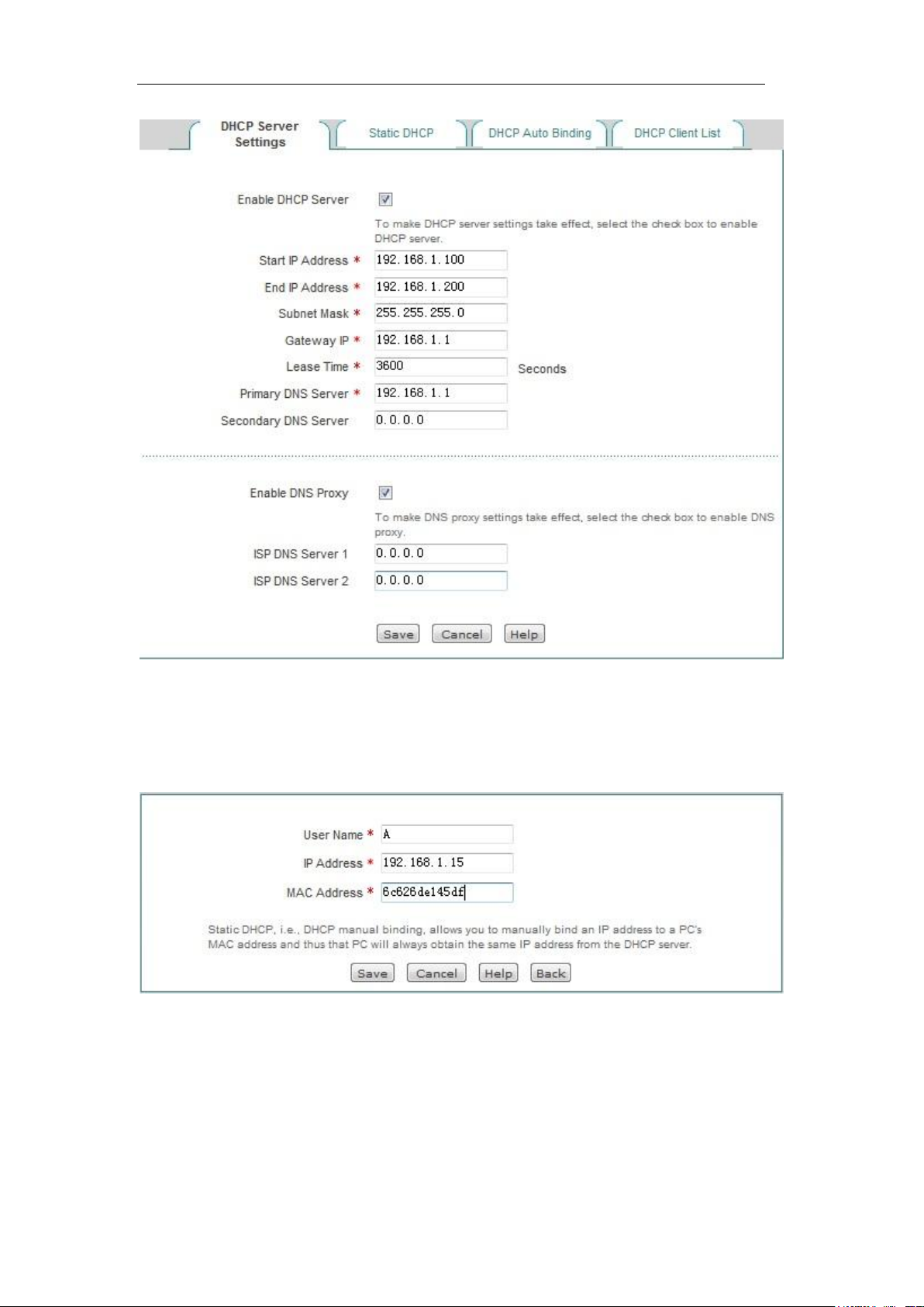
6.4.4 DHCP client list
For the IP address already assigned to the network computer, its information can be
viewed in the DHCP client list. Information as shown in the figure below: The DHCP server
assigns the IP address of 192.168.1.100 in the address pool to the network computers
whose MAC address is 6C:62:6D:E9:6D:13, and the rest of the time for the computer to
lease this IP address is 86333 seconds.
http://www.level1.com Page 39
Page 40
Chapter 6 Network parameters
Figure 6-18 DHCP client list
6.4.5 Case of DHCP configuration
Application requirements
In this example, the device must have the DHCP function enabled, and the starting
address is 192.168.1.10, with a total number of 100 allocable addresses. The host with
the MAC address of 00:21:85:9B:45:46 assigns the fixed IP address of 192.168.1.15,
while the host with the MAC address of 00:1f:3c:0f:07:f4 assigns the fixed IP address of
192.168.1.10.
Configuration steps
The first step is to enter into the Network parameters -> DHCP server -> DHCPservice
settings page.
The second step is to enable the DHCP function, and configure the related DHCP service
parameters (as shown in Figure 6-20), and click <Save> after the end of configuration.
http://www.level1.com Page 40
Page 41
Chapter 6 Network parameters
Figure 6-19 DHCP service settings - Instance
The third step is to enter the Network parameters -> DHCP server-> Static DHCP page,
and click <Add new entry>, to configure the two static DHCP instances in the request
(such as Figure 6-21, Figure 6-22).
Figure 6-20 Static DHCP configuration - Instance A
http://www.level1.com Page 41
Page 42
Chapter 6 Network parameters
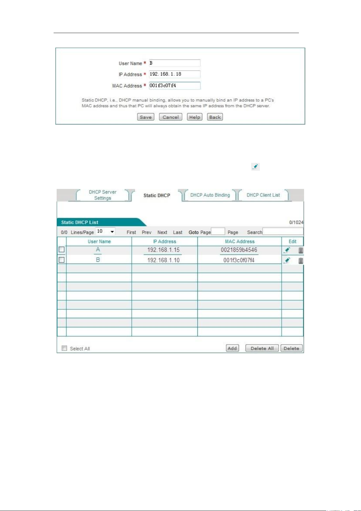
Figure 6-21 Static DHCP configuration - Instance B
At this point, the configuration is complete, and you can view the information about 2 static
DHCP entries in the "Static DHCP information list", as shown in Figure 6-23. If
configuration errors are found, you can click the corresponding item's icon directly and
enter into the Static DHCP configuration page for modification and saving.
Figure 6-22 Static DHCP information list - Instance
6.5 DDNS configuration
This section describes the Network parameters ->DDNS configuration page and
configuration methods. Includes: application for DDNS account, configuration of DDNS
service, DDNS authentication.
http://www.level1.com Page 42
Page 43
Chapter 6 Network parameters
Dynamic DNS (DDNS) is a service to resolve a fixed domain name to a dynamic IP
address (such as ADSL dial-up Internet access) services. You need to apply to the DDNS
service provider for this service, and various service providers provide the specific service
of DDNS according to the actual situation. The DDNS service provider reserves the rights
to change, interrupt or terminate part or all of the network services. At present, the DDNS
service is free of charge, when the DDNS service provider may charge some fee for using
DDNS services in providing network services. In this case, HiPER Technology will give a
notice as soon as possible. If you refuse to pay such expenses, you cannot use the
related services. At the free stage, HiPER Technology does not guarantee the DDNS
service must be able to meet the requirements, nor guarantee the service will be
uninterrupted, nor guarantee the timeliness, safety, and accuracy of network services.
6.5.1 DDNS authentication
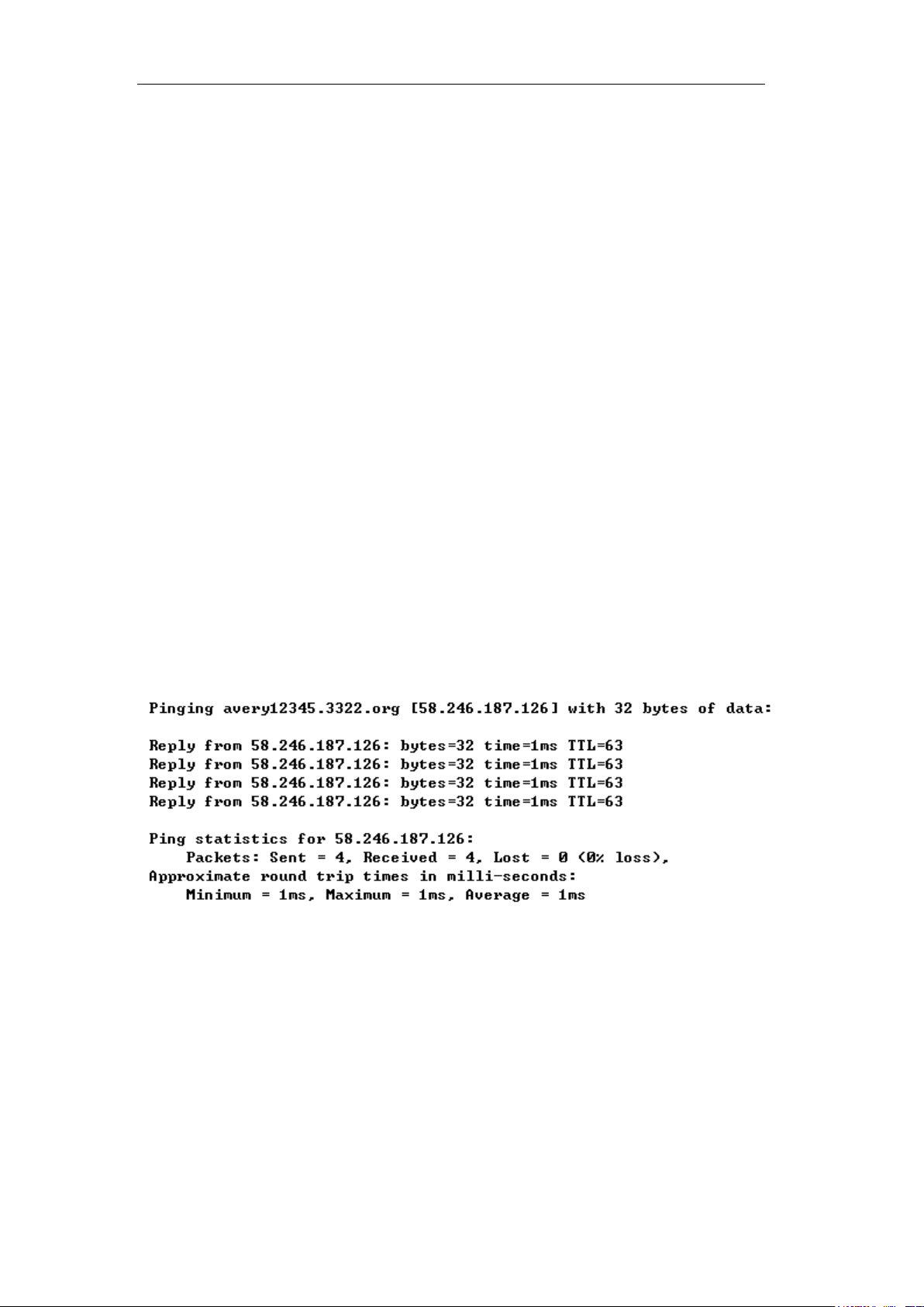
You can use the Ping command (for example: ping avery12345.3322.org) in the DOS
status of intranet computers, to check if the DDNS update is successful. Upon seeing the
correctly parsed-out IP address (for example: 58.246.187.126), it indicates that domain
name resolution is correct. Note: Under normal circumstances, the device's IP address will
not be pinged from the Internet after NAT is used on the device but only the IP address for
that domain name can be parsed out.
1. Only when the IP address assigned by ISP (Such as China Telecom) to the WAN port
connection line can the domain name be sure to be accessed by Internet users.
2. The DDNS function can help the Dynamic IP use VPN and server mapping.
6.6 UPnP
Universal Plug and Play (UPnP) is an architecture for common peer network connections
http://www.level1.com Page 43
Page 44
Chapter 6 Network parameters
used for PCs and intelligent devices (or instruments). Using UPnP means simpler, more
choices and more innovative experiences. The network products supporting Universal
Plug and Play need only be physically connected to the network to begin to work.
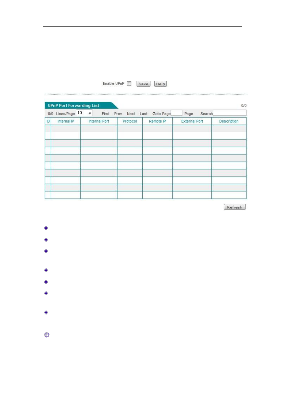
This section describes the Network parameters ->UPnP page and configuration. When
configuring UPnP in this page, you need to simply enable or disable this feature.
Figure 6-23 UPnP configuration
Enable UPnP: Ticking the check box for enabling the UPnP feature.
Internal address: The host IP address when port translation is needed in the intranet.
Internal port: The port number provided by the host when port translation is required
in the intranet.
Protocol: The protocol used by the UPnP port in translation (TCP/UDP).
Peer address: The IP address of the peer host.
External ports: The port number of the device used for port translation. This port is the
service port the device provides to the Internet.
Description: The description information given when an application requests port
translation to the device through UPnP.
Tip: It is recommended not to enable the UPnP feature when this feature is not in use.
http://www.level1.com Page 44
Page 45

Chapter 7 Wireless configuration
Chapter 7. Wireless configuration
In the wireless configuration, the relevant wireless functions and parameters are mainly
set in the device, including: basic settings, wireless security settings, wireless MAC
address filtering, and wireless advanced configuration. In addition, you can also view the
status information about the wireless host.
7.1 Basic settings
This section describes the Wireless Configuration -> Basic settings page and the
configuration methods. In this page, you can configure the AP working mode, SSID,
wireless mode, channel, channel bandwidth, enabling or disabling the SSID broadcast
and other functions of the device. In this section, the AP working mode is used: The
wireless basic configuration is introduced in the order of AP Mode, APClient Mode and
WDS.
http://www.level1.com Page 45
Page 46
Chapter 7 Wireless configuration
7.1.1 AP Mode
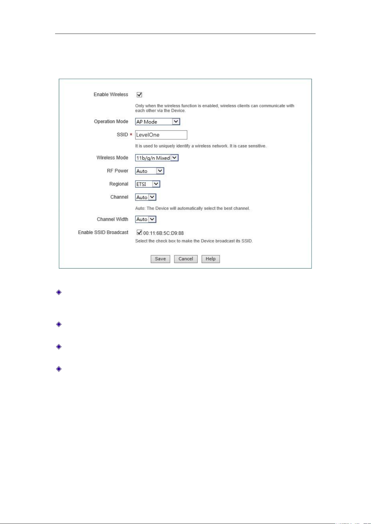
Figure 7-1 AP Mode
Enable wireless function: Only after the wireless function is enabled can the wireless
clients be connected to the device, to have wireless communications through the
device, connect and access the cable network to which the device is connected.
AP working mode: The AP Mode is selected here, namely the pure AP mode, in which
the peer device can be an AP Client mode and single client.
SSID: SSID (Service Set Identification) is used to uniquely identify a string of wireless
network, and is case sensitive.
Wireless mode: This parameter is used to set the modes of a wireless device,
providing three options: only 11g, only 11n, and 11b/g/n hybrid.
Only 11g: pure 802.11g mode, in which the maximum rate is up to 54M bps. The
wireless sites compatible with the IEEE 802.11g standard can be connected to
the device.
Only 11n: Pure 802.11n mode, in which the maximum rate is up to 150M bps.
The wireless sites compatible with the IEEE 802.11n standard can be connected
to the device.
11b/g/n hybrid: The wireless sites in compliance with IEEE 802.11b, 802.11g or
802.11n standard will be connected according to their modes, with the maximum
rates of 11M bps, 54M bps and 150M bps respectively.
http://www.level1.com Page 46
Page 47

Chapter 7 Wireless configuration
Channel: This parameter is used to select the frequency bands in which the wireless
network works, with the available range from 1 to 11, and it provides automatic
options, which means that the device can automatically select the optimal frequency
band. If there is more than one wireless device, the settings of frequency band of the
devices cannot affect each other.
Channel bandwidth: The channel bandwidth occupied by setting the wireless data
transmission, with the options: Auto, 20M and 40M. Note that this parameter works
only with the wireless site accessed using the 802.11n standard. For those wireless
sites using the 802.11b or 802.11g standard, only the channel bandwidth of 20M can
be used.
Auto: When Auto is selected, it means the wireless sites accessed using the
802.11n standard will use the channel bandwidths of 20M or 40M according to
the results of the negotiation with the accessed peer ends.
20M: When 20M is selected, it means the wireless sites accessed by using the
802.11n standard will use the channel bandwidth of 20M.
40M: When 20M is selected, it means the wireless sites accessed by using the
802.11n standard will use the channel bandwidth of 20M.
SSID broadcast: Enables or disables the SSID broadcast function. If this function is
enabled, the device will broadcast its own SSID to all the wireless sites so that the
wireless sites without SSID (null) will get the correct SSID, to be able to connect to
the device, and join into the wireless network with this SSID identifier. This function is
enabled at risk (illegal sites are very easy to get the SSID information), so it is
generally recommended to disable this function.
Tip:
1. The device enables the wireless function by default and its work mode is AP Mode.
2. After the wireless parameters are modified, the device's wireless module will reboot,
and rebooting of the wireless module will disconnect all wireless connections.
3. The AP work modes function differently, and should be selected according to the
specific occasions, uses in configuration.
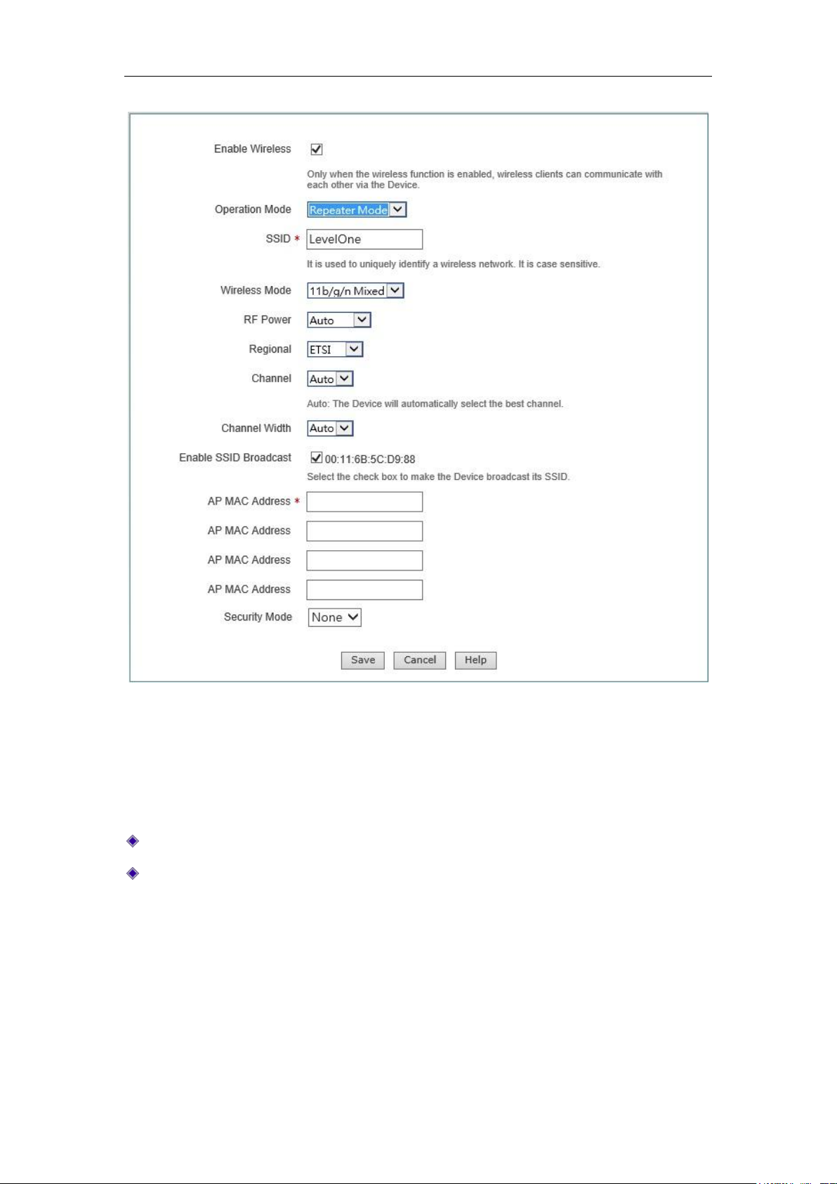
7.1.2 Repeater Mode
The device can exchange data with the network devices and single clients in Bridge Mode,
Repeater Mode, Lazy Mode when its work mode is set to Repeater Mode, to realize
network connectivity.
http://www.level1.com Page 47
Page 48
Chapter 7 Wireless configuration
Figure 7-2 Repeater Mode
For the meaning of enabling wireless function, AP working mode, SSID, wireless mode,
channel, channel bandwidth, enabling SSID broadcast, see Section 7.1.1 AP Mode for
relevant explanations, and these terms will no longer be detailed if any in the subsequent
configuration.
MAC address of AP: MAC address of the peer device.
Security mode: The encryption mode used in the establishment of connection through
the WDS function, including four options, "No security mechanism", "WEP", "TKIP"
and "AES".
No security mechanism: It means that no encryption algorithms will not be used
to protect communication data in the data exchange process.
WEP: It means that the WEP encryption algorithm is used to protect
communication data during the data exchange process. For details, please refer
to the section 7.2.2 WEP.
http://www.level1.com Page 48
Page 49
Chapter 7 Wireless configuration
TKIP: It means that the TKIP encryption algorithm is used to protect
communication data during the data exchange process. For details, please refer
to the section 7.2.4 WPA-PSK/WPA2-PSK.
AES: It means that the AES encryption algorithm is used to protect
communication data during the data exchange process. For details, please refer
to the section 7.2.4 WPA-PSK/WPA2-PSK.
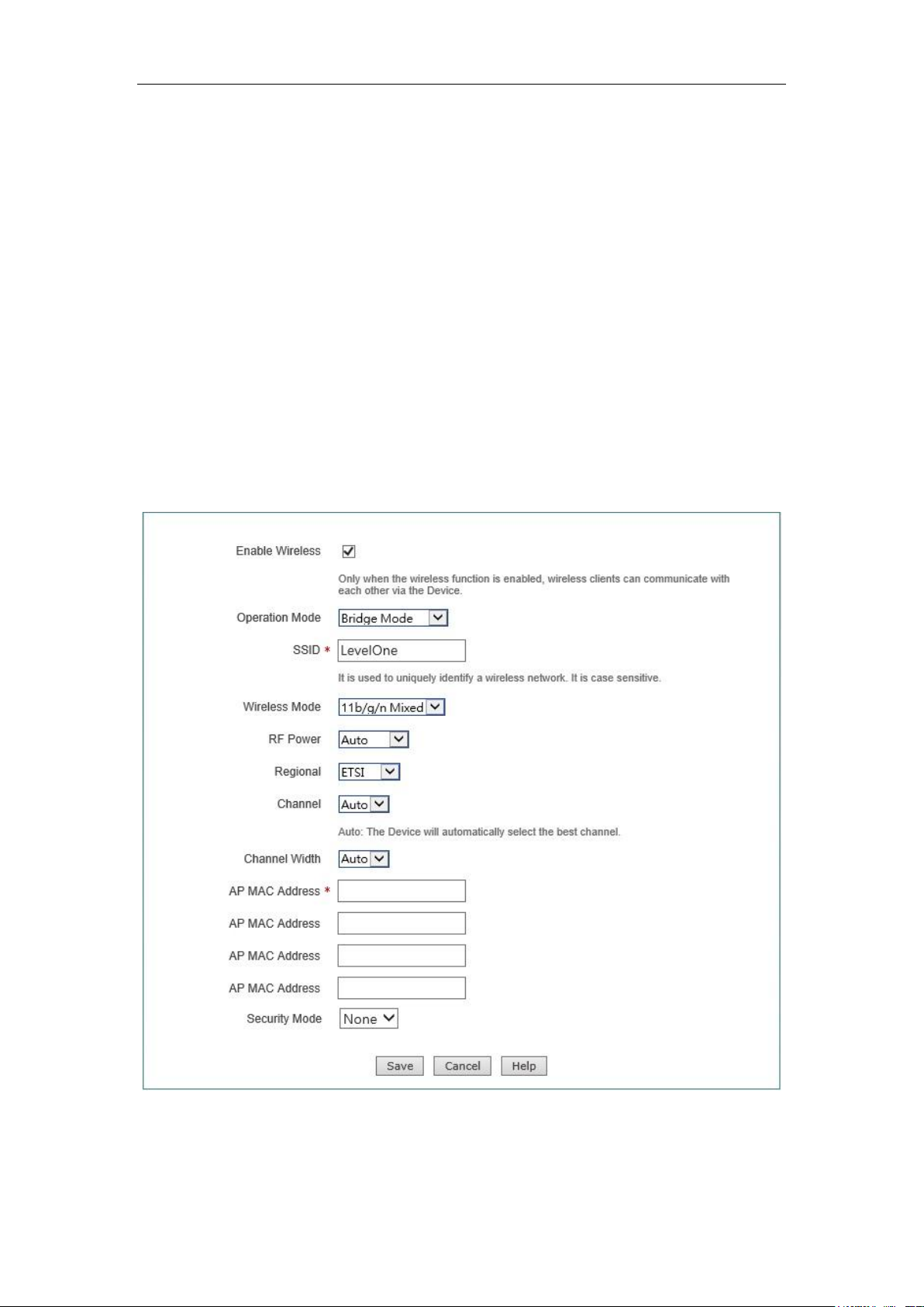
7.1.3 Bridge Mode
Bridge Mode, in which the device is connected to two or more wired networks, and the
device will no longer send wireless signals to other clients, to exchange data with the
network devices in Bridge Mode, Repeater Mode, Lazy Mode.
Figure 7-3 Bridge Mode
The meaning of related configuration parameters is the same as Repeater Mode. For
details, refer to the related description in Section 7.1.2 Repeater Mode.
http://www.level1.com Page 49
Page 50
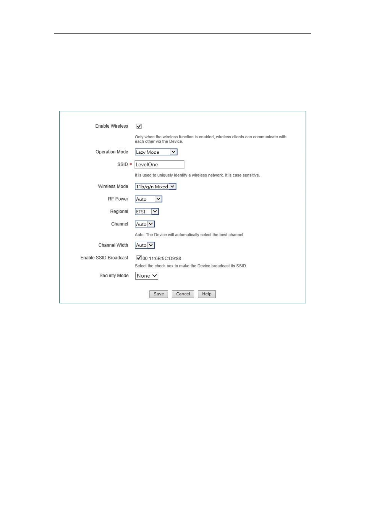
Chapter 7 Wireless configuration
7.1.4 Lazy Mode
The device can exchange data with network devices and single clients in the Repeater
Mode, Bridge Mode when its work mode is Lazy Mode, to realize network connectivity.
Figure 7-4 Lazy Mode
The meaning of related configuration parameters is the same as AP Mode and Repeater
Mode. For details, refer to the related description in Section 7.1.1 AP Mode and 7.1.2
Repeater Mode.
7.1.5 Wireless configuration instance
This section lists configuration instances where the device works in the AP Mode, AP
Client Mode and other AP working modes according to the five AP work modes of the
device.
(1) AP Mode configuration instance
http://www.level1.com Page 50
Page 51
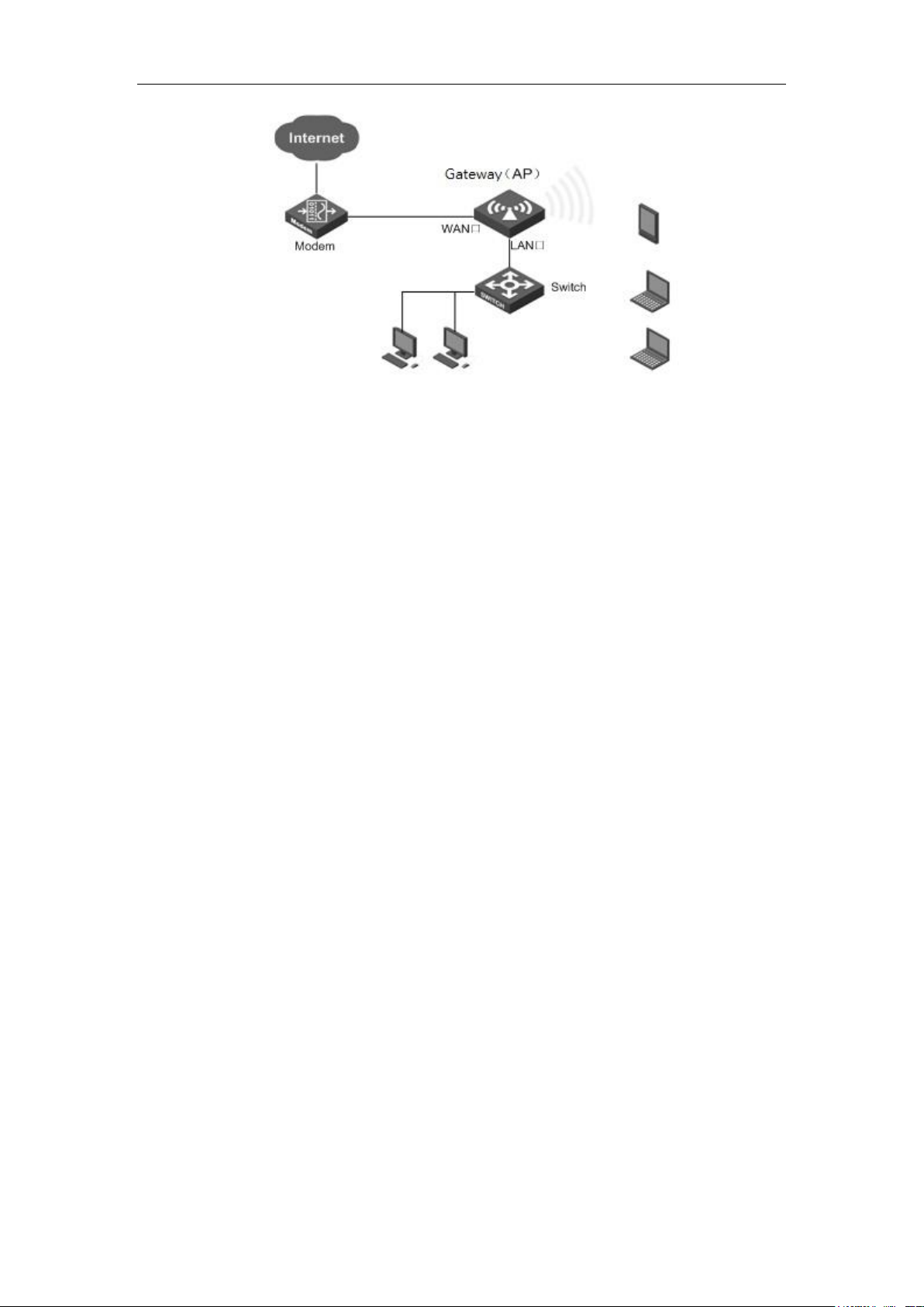
Chapter 7 Wireless configuration
Figure 7-5 AP Mode networking environment
1. Requirements: Some home users want to put desktop computer, laptop, Tablet PC,
smart phones on the Internet via wireless devices, and prevent users other than their
home from accessing to wireless devices.
2. Analysis: Desktop computers are connected via a network cable to the LAN port of a
wireless device. Laptops, Tablet PCs, etc. are wirelessly connected to a wireless
device and need to be authenticated.
3. Configuration steps:
1) Configure the TCP/IP properties for network computer.
2) Log on to the device, and configure the WAN1 according to the types of business
applied for by operators.
3) Enter into the Wireless Configuration -> Basic configuration page, to configure
the device's wireless basic parameters, as shown in the figure below, and set the AP
work mode as AP Mode.
http://www.level1.com Page 51
Page 52
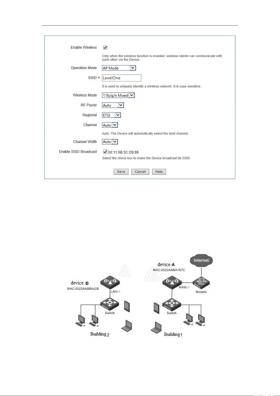
Chapter 7 Wireless configuration
Figure 7-6 AP Mode configuration
4) Enter into the Wireless configuration -> Wireless security settings page, to
configure the authentication modes and key for wireless communication.
Through the above configuration, wireless users can connect to the wireless devices so
long as they pass the authentication, and access to the Internet through it. For the way to
connect the network computer to the device, please refer to 0.
(2) WDS configuration instance
Figure 7-7 Repeater Mode networking environment
1. Requirements: The office personnel in Building 2 need to be wirelessly connected to
http://www.level1.com Page 52
Page 53
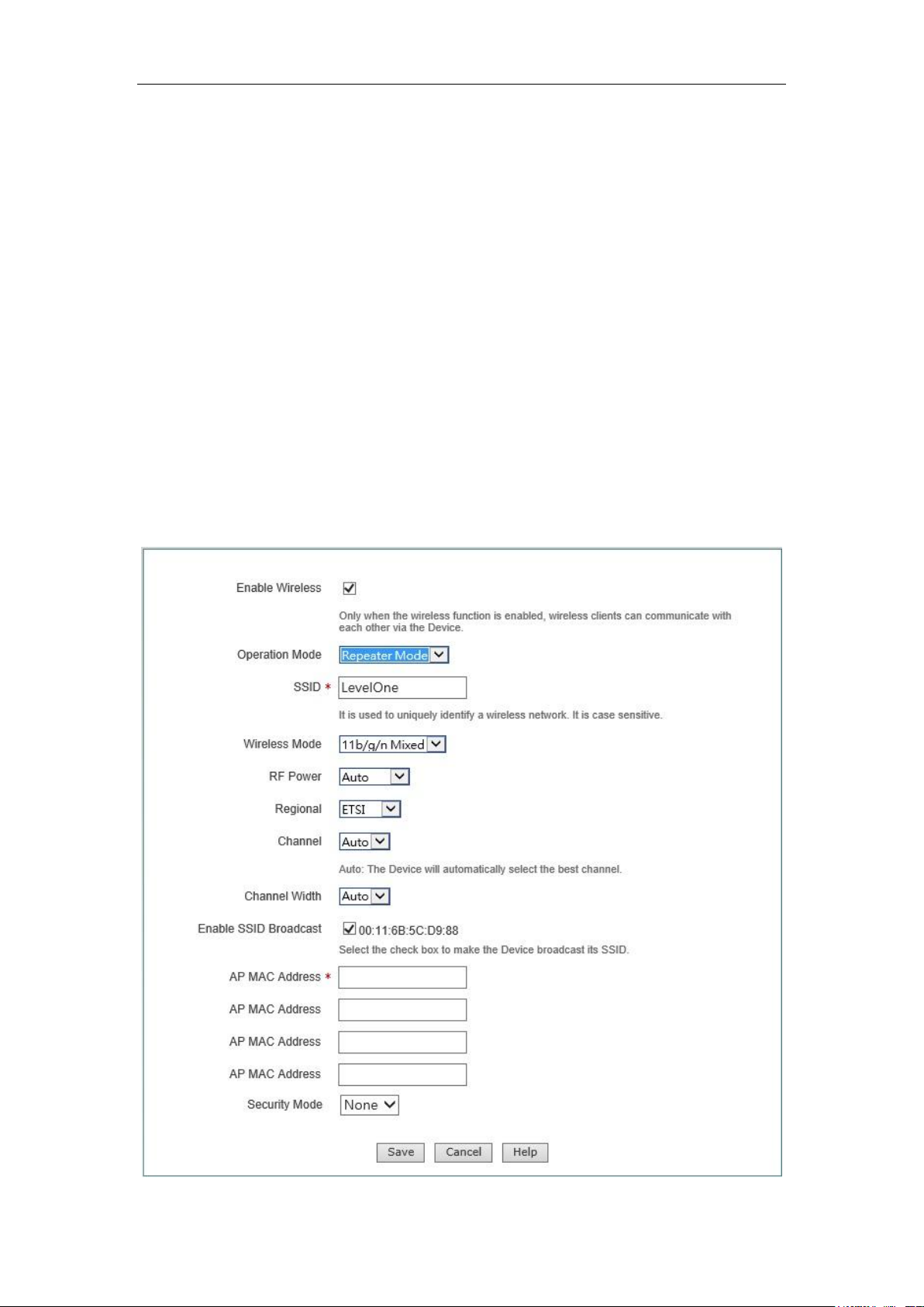
Chapter 7 Wireless configuration
Device A, and access to the Internet through Device A.
2. Analysis: Achieved by the following solutions
Solution I: Devices A and B are set to Repeater Mode.
Solution II: Devices A and B are set to Bridge Mode.
Solution III: Devices A and B are set to Repeater Mode, Bridge Mode respectively.
Solution IV: Devices A and B are set to Repeater Mode, Lazy Mode respectively.
Solution V: Devices A and B are set to Bridge Mode, Lazy Mode respectively.
Solution VI: Device A is set to AP Mode while Device B is set to AP Client Mode.
3. Configuration steps:
Solution I: Both are Repeater Mode
1) Configure the AP working mode of Device A as Repeater Mode, and the configuration
content is shown in the figure below:
http://www.level1.com Page 53
Page 54

Chapter 7 Wireless configuration
Figure 7-8 Repeater Mode instance
2) Configure the AP mode of Device B as Repeater Mode, and the SSID, wireless mode,
channel, channel bandwidth, security mode, pre-shared key are configured in the same
way as Device A, and the AP MAC address is: 0022AABB5428 (the MAC address of
Device A).
Through the above configurations, the office personnel in Building 1 can access to the
Internet through Device 2.
Tip:
1. The gateway of the computer in Building 2 is directed to the LAN port of Device A.
2. The IP address of LAN port of Device B is in the same network segment as the LAN
port address of Device A.
4. Connectivity verification:
Ping the LAN IP address of Device A on a computer in Building 2. If it can be pinged
successfully, then it means that the connection between the two wireless devices has
been established.
Solutions II, III, IV, V can follow Solution I.
Tip:
1. The device in Bridge Mode cannot be connected to the wireless single clients, such
as laptops, smart phones, etc.
2. The devices in Lazy Mode can be connected to the wireless single clients.
3. In configuration, the SSID and key of Devices A, B must be kept consistent, and the
MAC address of AP is that of the peer device (It is not required to configure the MAC
address of the peer device when the AP mode is Lazy Mode).
4. Both Devices A and B must be on the same network segment, and the network
gateway addresses for all the computers in the intranet is directed to Device B.
7.2 Wireless security settings
This section describes the interfaces and configuration methods of Wireless
configuration -> Wireless security configuration. This device provides three wireless
security mechanisms, WEP, WPA/WPA2, WPA-PSK/WPA2-PSK, while users are allowed
not to use the security mechanism. In the following sections, the meaning of their
configuration parameters are described separately.
http://www.level1.com Page 54
Page 55
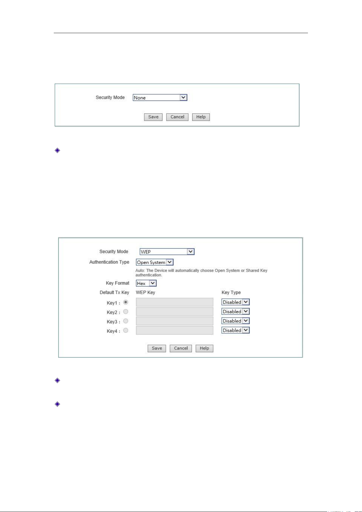
Chapter 7 Wireless configuration
7.2.1 No security mechanism
Figure 7-9 None
Security mechanism: "No security mechanism" is selected here, which means that
this device does not allow any security mechanism to authenticate the other wireless
devices or wireless clients of the access device.
7.2.2 WEP
Figure 7-10 WEP
Security mechanism: Selecting "WEP" here means that the device will use the most
basic WEP security mechanism provided by the 802.11 Protocol.
Authentication type: When using the WEP encryption mechanism, three options,
automatic, open systems, Shared keys are available:
Auto: Means that the device can automatically choose Open System or
Pre-shared key mode according to the requests of wireless clients.
Open system: Here, the wireless clients can pass the authentication and
associate with the wireless devices under the premise of providing no
http://www.level1.com Page 55
Page 56
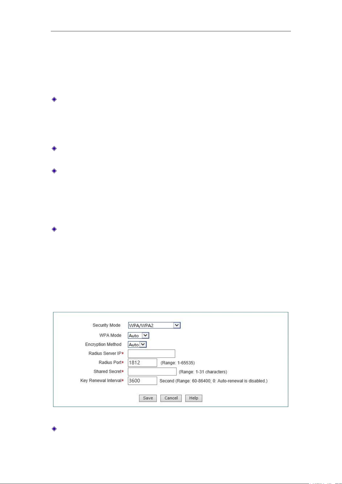
Chapter 7 Wireless configuration
authentication key. To perform data transmission, you must provide the correct
key.
Shared key: Here, the wireless client host must provide a correct key to pass the
authentication; otherwise, it cannot be associated with the wireless devices, and
cannot perform data transmission.
Key format: Two formats, hexadecimal code and ASCII code are provided:
When the hexadecimal code is used, the key characters can be 0 ~ 9, A, B, C, D,
E, F.
When the ASCII code is used, the key characters can be all ASCII codes.
Key selection: Users can enter 1 ~ 4 keys according to needs and these 4 keys can
take different types of keys.
WEP key: Sets the key value, and the length of the key is affected by key types:
When choosing a 64 - bit key, you can input 10 hexadecimal characters or 5
ASCII characters.
When choosing a 128 - bit key, you can input 26 hexadecimal characters or 13
ASCII characters.
Key types: Selects key types, and provides three options, Disable, 64 bits, 128 bits.
Among them, Disable means not to use the current key, but 64 bits, 128 bits, and
used to specify the length of the WEP key.
7.2.3 WPA/WPA2
Figure 7-11 WPA/WPA2
Security mechanism: Selecting "WPA/WPA2" here means that the device will use
WPA or WPA2 security mechanism. Under the security mechanism, the device will
http://www.level1.com Page 56
Page 57
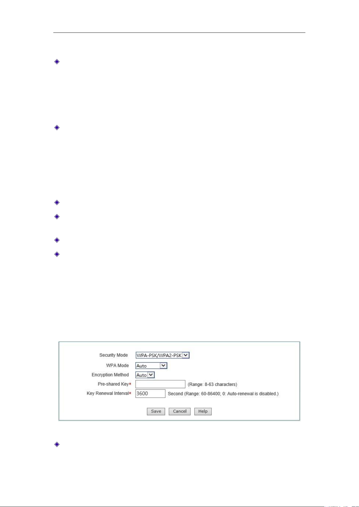
Chapter 7 Wireless configuration
use the Radius server for authentication and obtaining the key.
WPA version: Sets the security mode this device will use:
Auto: Means that the device can automatically choose WPA or WPA2 safe mode
according to the requests of wireless client.
WPA: Means that this device will use the safe mode of WPA.
WPA2: Means that the device will use the safe mode of WPA2.
Encryption algorithm: It is used to encrypt wireless data, with the options like Auto,
TKIP and AES.
Auto: Means that the device will automatically choose encryption algorithms
according to needs.
TKIP: Means that all wireless data will use TKIP as the encryption algorithm.
AES: Means that all wireless data will use AES as the encryption algorithm.
Radius Server IP: It is used to the identity the authentication of the wireless hosts.
Radius port: The Port number of service used by the Radius server for identifying the
authentication of the wireless hosts.
Radius password: Sets the password for accessing to the Radius service.
Key update cycle: It is the timed update cycle used to specify the key. Value range is
60 ~ 86400, in the unit of seconds. The default value is 3600, which means no update
when the value is 0.
7.2.4 WPA-PSK/WPA2-PSK
Figure 7-12 WPA-PSK/WPA2-PSK
Security mechanism: Here, you can select "WPA-PSK /WPA2-PSK", which means
that the device will use WPA-PSK/WPA2-PSK security mechanism. Under this
http://www.level1.com Page 57
Page 58

Chapter 7 Wireless configuration
security mechanism, this device will use the WPA mode based on the Pre-Shared
key.
WPA version: Sets the security mode this device will use:
Auto: Means that the device can automatically choose WPA-PSK or WPA2-PSK
safe mode according to the requests of wireless clients.
WPA: Means that the device will use the safe mode of WPA-PSK.
WPA2: Means that the device will use the safe mode of WPA2-PSK.
Encryption algorithm: It is used to encrypt wireless data, with the options like Auto,
TKIP and AES.
Auto: Means that the device will automatically choose encryption algorithms
according to needs.
TKIP: Means that all wireless data will use TKIP as the encryption algorithm.
AES: Means that all wireless data will use AES as the encryption algorithm.
Pre-shared key: The preset initialization key, with the value of 8 ~ 63 characters.
Key update cycle: It is the timed update cycle used to specify the key. Value range is
60 ~ 86400, in the unit of seconds. The default value is 3600, which means no update
when the value is 0.
7.3 Wireless MAC Address Filtering
This section describes the Wireless configuration->MAC filtering page and the
configuration of wireless MAC address filtering. By setting the MAC address filtering
function, you can enable or disable wireless hosts to or from access to the device and the
wireless network.
http://www.level1.com Page 58
Page 59
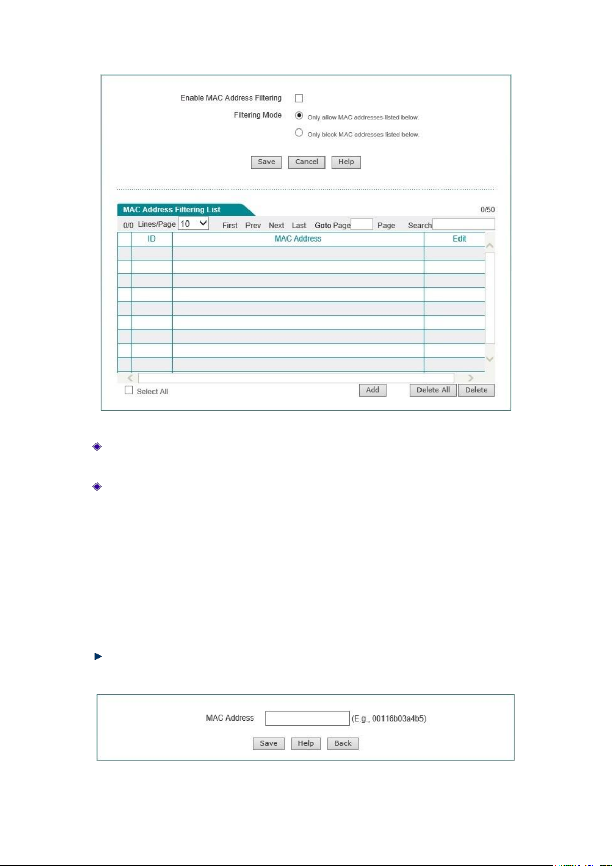
Chapter 7 Wireless configuration
Figure 7-13 Wireless MAC Address Filtering
Enable MAC address filtering: Enable or disable the MAC address filtering function,
checking it means to enable it.
Filtering rules: Sets the rules for MAC address filtering.
Permission: Only allows the MAC addresses in the list to access the wireless
network: It indicates that only the wireless clients that correspond to the MAC
addresses in the MAC address filtering information list are allowed to access to
the device but disallow the wireless clients out of the filtering table to access.
Permission: Only disallows the MAC addresses in the list to access the wireless
network: It indicates that only the wireless clients that correspond to the MAC
addresses in the MAC address filtering information list are disallowed to access
to the device but allow the wireless clients out of the filtering table to access.
Add new entry: Click this button to enter into MAC address filtering configuration
page to configure the MAC addresses to be filtered, as shown in the figure below.
Figure 7-14 Configuration of MAC address filtering
http://www.level1.com Page 59
Page 60
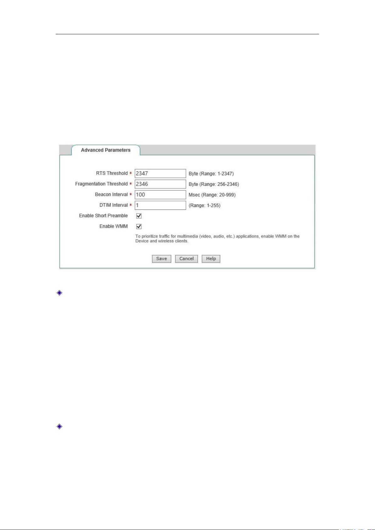
Chapter 7 Wireless configuration
7.4 Wireless Advanced Configuration
This section describes the meaning of the wireless advanced parameters in the Wireless
Configuration-> Advanced.
In this page, you can set wireless advanced parameters, and under normal circumstances,
keep the default values of these parameters. If you have special needs, you can configure
in this page.
Figure 7-15 Advanced Wireless Settings
RTS threshold: When a packet exceeds this threshold, it will activate the RTS
mechanism. The device will send RTS (Request to Send) packet to the destination
site for negotiation before sending data frames. After receiving an RTS frame, the
wireless site will respond to the device by sending a CTS (Clear to Send) frame,
which means wireless communication can be made between both of them. The value
range is generally 1-2347 bytes, and the default is 2347 bytes.
The RTS mechanism is used to avoid data transmission conflicts in the wireless LAN.
The transmission frequency of the RTS packet needs to be set reasonably, and
setting of the RTS threshold requires weighing. If this parameter is set to low, the
transmission rate of RTS packets is increased, consuming more bandwidths, which
may significantly affect the throughput of other network packets. But the more
frequently the RTS packet is sent, the more quickly the system can be recovered from
disruption or conflict.
Segmentation threshold: It is used to define the maximum transmission length of the
wireless data packets allowed by the wireless MAC layer to be transmitted, when the
length of Data frames exceeds this value, they will automatically be segmented into
multipledata frames, and then transmitted again. If the segmented transmission is
interrupted, only the parts that are not sent successfully need to be sent, and the
throughput of segmented packets is generally low. The value range is generally
http://www.level1.com Page 60
Page 61

Chapter 7 Wireless configuration
256-2346 bytes, and the default is 2346 bytes.
The transmission efficiency for large segments is high, but if there is a clear conflict in
the wireless network, or if the network is used at a high frequency, the reduction of
segments can improve the reliability of data transfer. In most cases, keep the default
value as 2346.
Beacon interval: The device synchronizes the wireless network connection through
regular Radio Beacon frames. This parameter is used to define the transmission
interval of beacon frames, which are transmitted periodically at the specified time
interval. The value range is generally 20-999 ms, and the default is 100 ms.
DTIM interval: This parameter is used to specify the transmission interval for the
Delivery Traffic Indication Message (DTIM). DTIM interval is used to decide the
frequency of beacon frames containing Traffic Indication Map (TIM) to be transmitted.
TIM will issue a warning to the sites entering into the sleep status, by indicating that
the data is to be received. DTIM is usually the multiple of beacon interval. Its use
range is 1-255, and its default value is 1.
Enable Short Preamble: Enables or disables Short Preamble.
When enabled, the short preamble type will be used. The short preamble type
can provide better performance. Because the use of short preamble can
minimize the costs, thus maximizing the network data throughput.
When disabled, the long preamble type (Long Preamble) will be used, and able
to provide more viable connections and a large range of connections.
Enable WMM: Allows you to enable or disable the WMM support. WMM (Wi-Fi
Multimedia) is a subset of the 802.11e standard. WMM allows wireless traffic to have
a priority range based on the data type. Time-sensitive information, such as video or
audio, will have a higher priority than the normal traffic. To use the WMM function
properly, wireless clients must also support WMM.
7.5 Client List
This section describes the Wireless Configuration -> Client List page.
Through the "List of the wireless host status information", you can view the status
information of the wireless hosts currently connected to the device. In addition, through
the "List of the wireless host status information", you can also easily set the MAC address
filtering function.
http://www.level1.com Page 61
Page 62
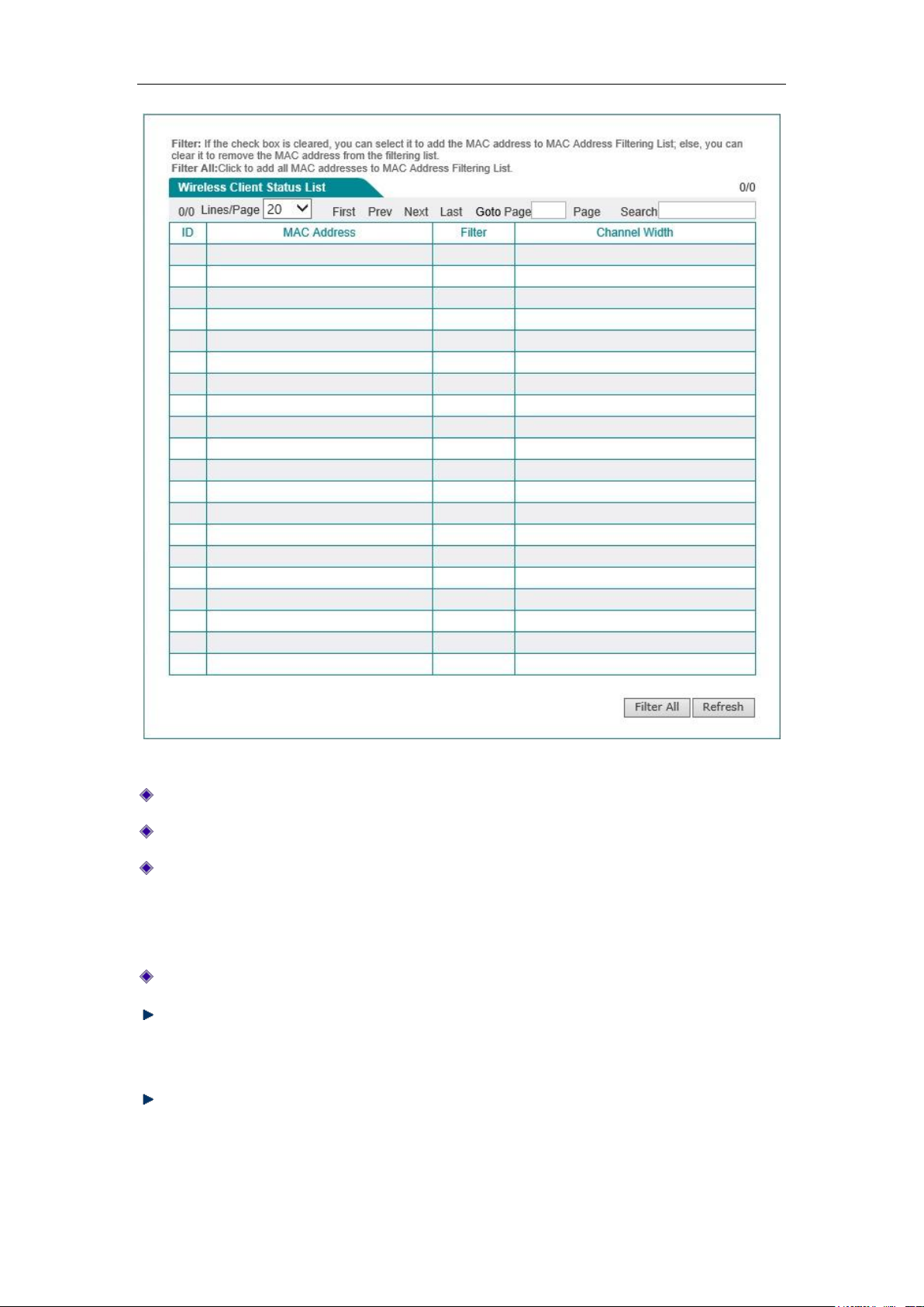
Chapter 7 Wireless configuration
Figure 7-16 Client List
ID: Serial number.
MAC address: The MAC address of the wireless host.
Filter: Selecting it to indicate that the current MAC address has been added into the
"List of MAC address filter information" (which can be viewed in the Wireless
configuration --> Wireless MAC address filtering page), while not selecting it
means that the current MAC address filtering is not set.
Channel bandwidth: The theoretical data transfer rate of the data channel.
All filter: Click <All filter>, to conduct the MAC address filtering for all wireless hosts
whose filtering is not enabled in the current list, and to add all the MAC addresses to
the "MAC address filtering list".
Refresh: Click <Refresh>, to view the latest wireless host status and statistical
information.
http://www.level1.com Page 62
Page 63

Chapter 8 Wireless configuration
Chapter 8. Advanced Configuration
The features described in this chapter include: NAT and DMZ, route configuration, network
vanguard defense, port mirroring, port VLAN and SYSLOG configuration.
8.1 NAT and DMZ configuration
This section describes the features and configuration methods of the Advanced
Configuration->NAT and DMZ configuration page.
8.1.1 Description of NAT functions
NAT (network address translation) is a technology to map an IP address field (such as Intranet) to
another IP address field (such as the Internet). NAT was designed to solve the problem of
increasing shortage of IP addresses, NAT allows a private network to use the IP address in any
range internally, and for the public Internet, it is reflected as limited range of public network IP
addresses. Since the internal network can be effectively isolated from the outside world, so NAT
can also provide some assurance for network security.
LEVELONE routing products provide flexible NAT function. The following will detail its
characteristics.
1. NAT address space
In order to correctly conduct the NAT operation, any NAT device must maintain two address
spaces: one is the private IP addresses used internally by Intranet hosts, which is represented by
"Internal IP address" in the device. Another is the public network IP address for external use,
which is represented by "External IP address" in the device.
2. NAT Static mapping and virtual server (DMZ host)
After the NAT feature is enabled, the device blocks the access requests that originate outside.
However, in certain application environments, a computer in the external network hopes to access
http://www.level1.com Page 63
Page 64

Chapter 8 Wireless configuration
to the Intranet server through the device, at this point, the static NAT mapping or virtual server
(DMZ host) needs to be set up on the device in order to achieve this objective.
With the static NAT mapping function, a one-to-one mapping relationship can be established
between<External IP address + External port>and<Internal IP address + Internal port>, so that
all the service requests for a specified port of the device will be forwarded to the matching intranet
server, and the computer in the external network can access to the services provided by this server.
In some cases, a network computer needs to be fully exposed to the Internet, in order to achieve
two-way communications, and at this time, you will need to set up this computer to a virtual
server (DMZ host). When an external user accesses to the public network address that is mapped
to the virtual server, the device will forward the packets directly to the virtual server.
Tip: The computer that is set to a virtual server will lose the firewall protection of the device.
The priority of NAT static mappings is higher than the virtual server. When the device receives a
request from an external network, it will first check to see if there is a matching NAT static
mapping based on the IP address and port number of the external access requests, and send the
request messages matching the static NAT mapping to the Intranet computers if any. If there are no
matching static mappings, it will check to see if there is a matching virtual server.
3. Two types of NAT rules
The device provides two NAT types: "Easy IP" and "One2One".
Easy IP: The translation of network port addresses. Multiple internal IP addresses are mapped to
the same external IP address. It can dynamically assign a port associated with a single external
address for each internal connection, and maintain the mapping of these internal connections to an
external port, thus enabling multiple users to use a public network address to communicate with
the external Internet.
One2One: The translation of static addresses. The internal IP and the external IP address are
subject to one-to-one mapping. In this mode, the port number will not change. It is typically
used to configure the extranet-access-to-intranet server: The network servers still use private
addresses, and provide the public IP address assigned to it to the external network users.
We refer to each specific NAT configuration as "NAT rules". The exit IP address and lines must be
specified when configuring the NAT rules. When there are multiple valid public network
addresses, each type of NAT rules can be configured with more than one. In practical application,
a mixture of different types of NAT rules often needs to be used.
8.1.2 Port Forwarding
This section describes the static NAT mapping functions of the device. Below is the description of
http://www.level1.com Page 64
Page 65
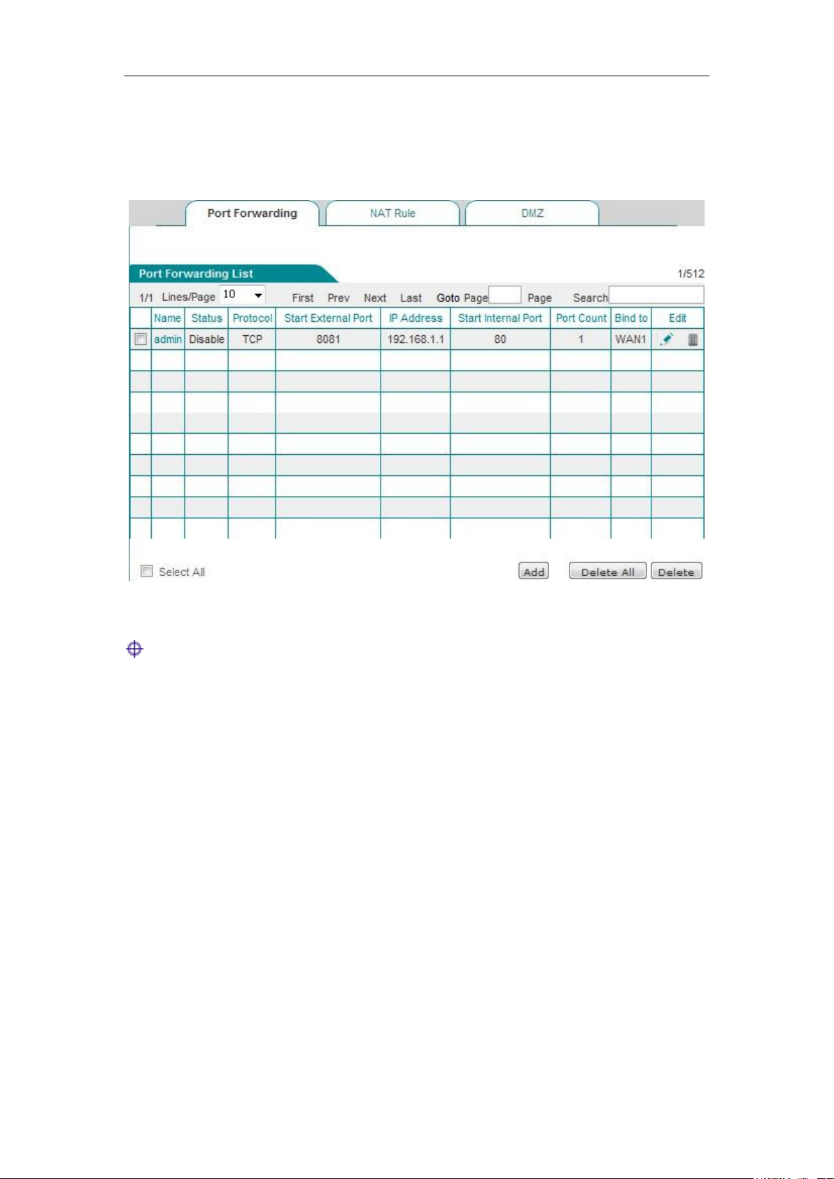
Chapter 8 Wireless configuration
the meaning of the parameters for the static NAT mapping list and the static NAT mapping
configuration.
1. Port Forwarding list
Figure 8_1 Port Forwarding list
Tip:
After enabling certain functions of the system, the list displays some NAT static mapping entries
(A static mapping entry named as "admin" is added in the list after remote management is enabled
in Systems management -> Remote management page, they cannot be edited or deleted in this
page.
2. Static NAT mapping configuration
Click <Add new entry> in the page of Figure 8_1 to enter the Static NAT mapping configuration
page, as shown in Figure 8_2. Here, the meaning of the parameters of the static NAT mapping
configuration is described.
http://www.level1.com Page 65
Page 66
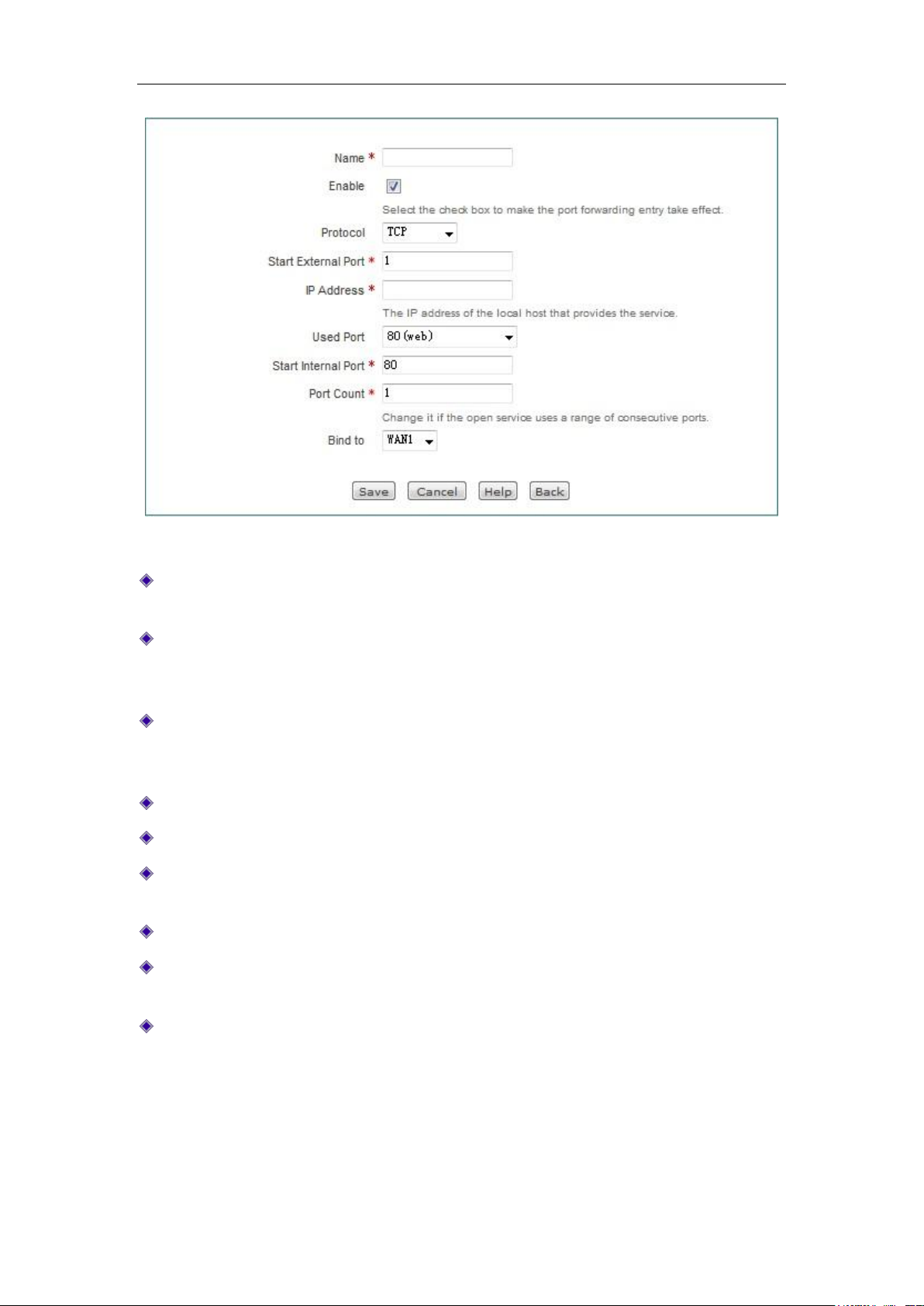
Chapter 8 Wireless configuration
Figure 8_2 Port Forwarding Settings
Static mapping name: The name of static NAT mapping, which is custom and cannot be
repeated.
Enable this configuration: Selecting it indicates that the static NAT mapping takes effect, and
not selecting it means that the static NAT mapping does not take effect, but retains its
configuration.
Protocol: The protocol type of packets, the available options are: TCP, UDP and TCP/UDP.
When you are unable to confirm that the protocol used by the application is TCP or UDP,
select TCP/UDP.
External starting port: The starting service port the device provides to the Internet.
IP address: The IP address of the computer as a server in the Intranet.
Common port: The port number that corresponds to the common protocol type for users'
choice. When you are unable to confirm the protocol, select TCP/UDP.
Internal starting port: The starting port of the services enabled by the network server.
Number of ports: A segment of ports starting from the internal starting port, whose maximum
value is set to 500.
NAT binding: Selects the interface bound by the static NAT mapping.
http://www.level1.com Page 66
Page 67
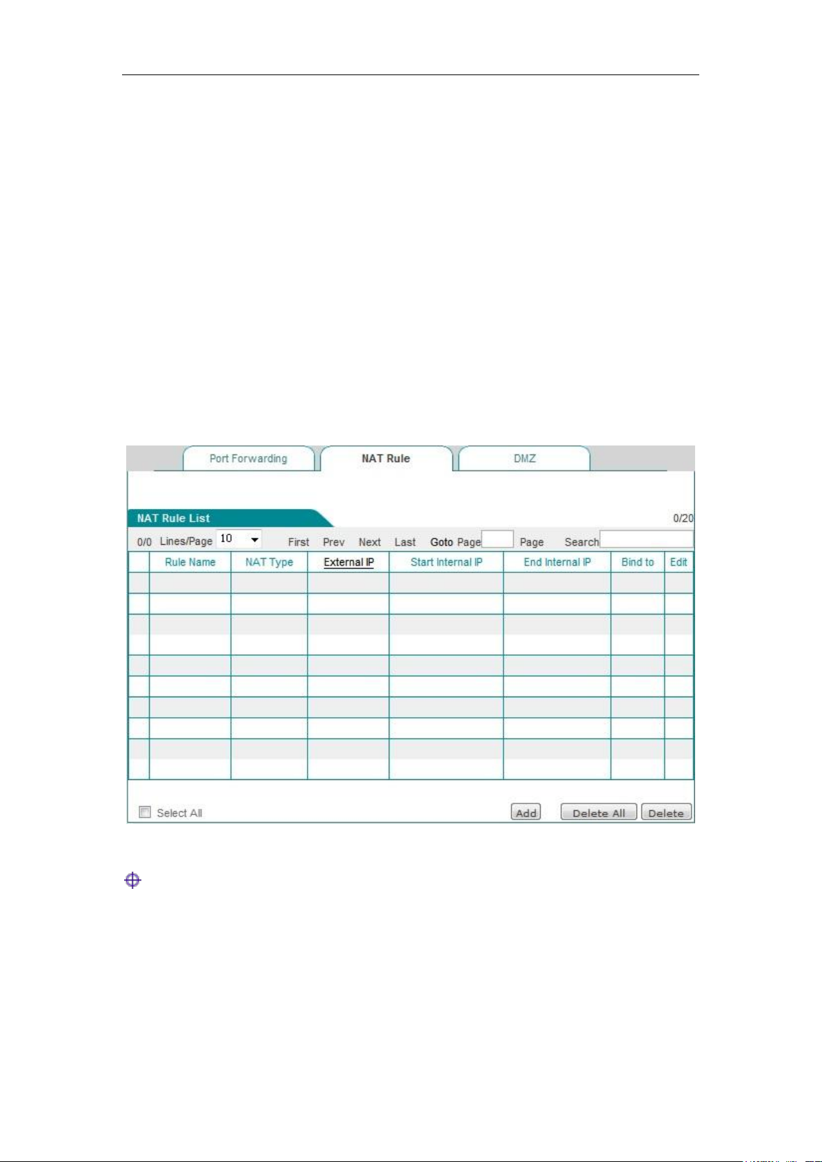
Chapter 8 Wireless configuration
8.1.3 NAT rules
The NAT rules features of the device are described below, including: NAT rule info lists, meaning
of Easy IP NAT rules configuration parameters, meaning of One2One NAT rules configuration
parameters.
1. List of NAT rules information
In NAT rules information list, you can see the configured NAT rules. As shown in Figure 8_3, it
has two NAT rules instances configured. The NAT type of an instance: EasyIP converts the
address with the intranet IP address of 192.168.1.20-192.168.1.25 to 200.200.202.20, and binds to
the WAN1 port to achieve Internet access. The NAT type of an instance: One2One converts the
address with the intranet IP address of 192.168.1.50-192.168.1-52 to 200.200.202.50,
200.200.202.51, 200.200.202.52, and binds to the WAN1 port to achieve Internet access.
Figure 8_3 List of NAT rules information
Tip: Multiple NAT rules are configured for the same object, and the rules configured last will
take effect first.
2. Easy IP
Click <Add new entry> in Figure 8_3 to enter the NAT rules configuration page. The following
describes the meaning of the parameters for configuring the NAT rules with the type of EasyIP.
http://www.level1.com Page 67
Page 68
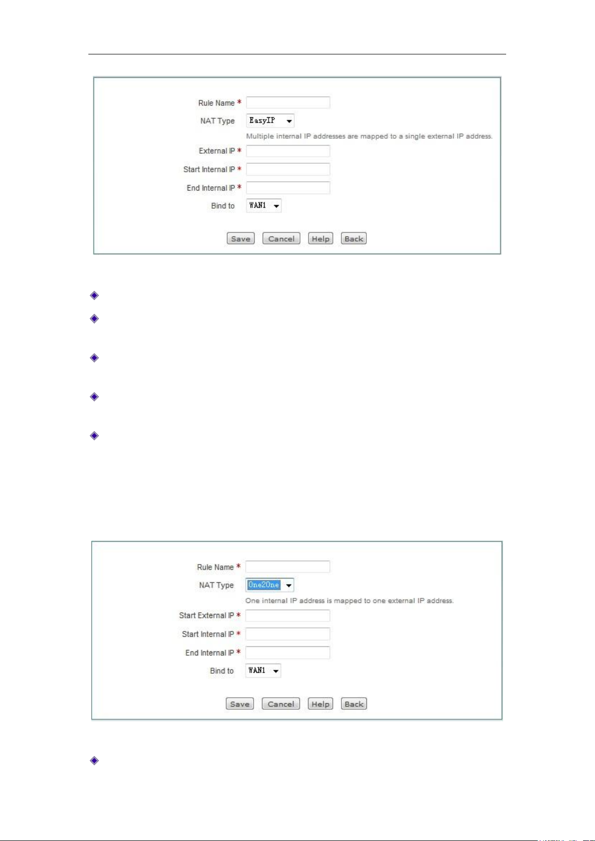
Chapter 8 Wireless configuration
Figure 8_4 Easy IP
Rule name: Customizes the name of the NAT rule.
NAT type: Selects EasyIP here, which means the internal IP address are mapped to the same
external IP address.
External IP address: In the NAT rule, the external IP address mapped to the internal IP
address.
Internal starting IP address, internal ending IP address: The IP address range for the
computers in the intranet that have the priority to use the NAT rules for Internet access.
Binding: Selects the interface bound by the static NAT mapping.
3. One2One
Select the NAT type as One2One in Figure 8_5. The meaning of the parameters for configuring
the NAT rules as One2One type is described here, and those parameters same as EasyIP are
repeated no longer here.
Figure 8_5 One2One
NAT type: Here, One2One is selected. The internal IP address and the external IP address are
http://www.level1.com Page 68
Page 69
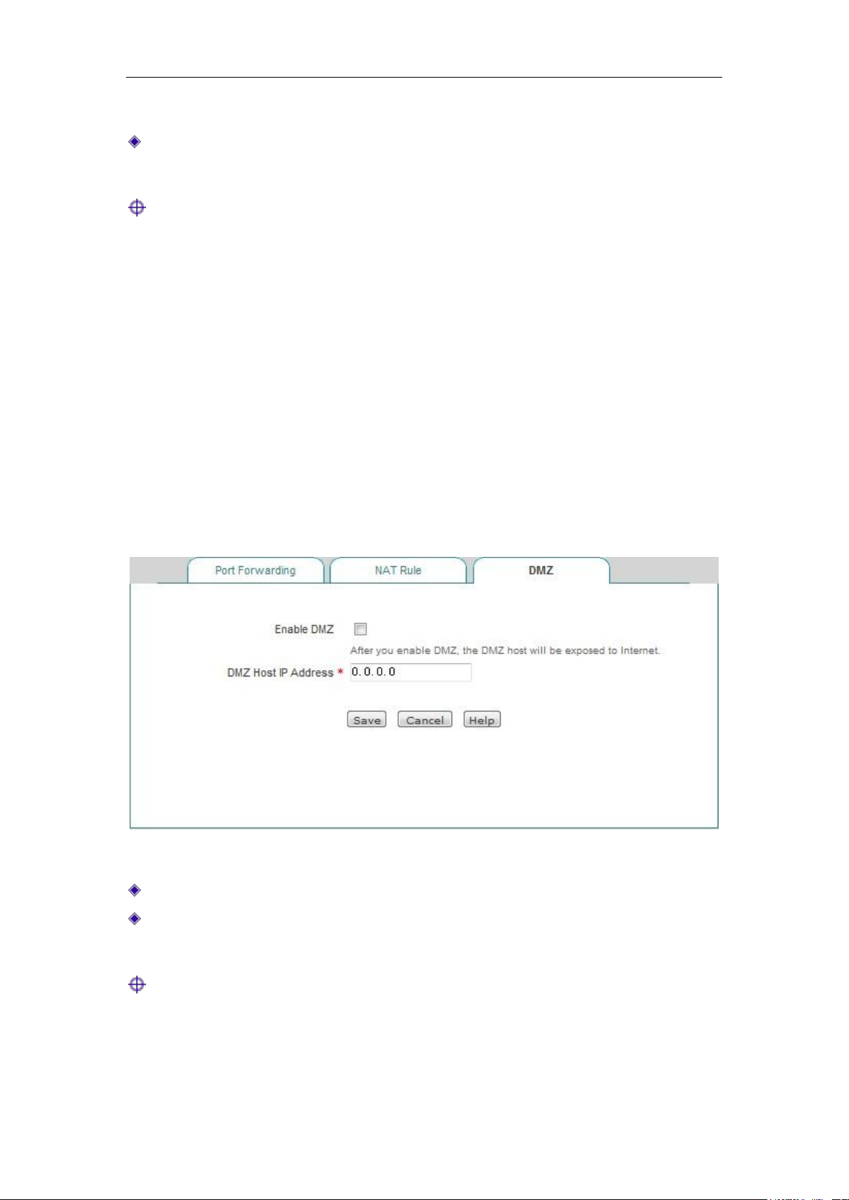
Chapter 8 Wireless configuration
subject to one-to-one mapping.
External starting IP address: In the NAT rule, the external starting IP address mapped to the
internal starting IP address.
Tip:
1. Each One2One rule can only bind 20 external addresses at maximum.
2. "External starting IP address" must be set, and the actually mapped external IP address is
gradually increased from the set value. For example, if "Internal starting IP address" is set to
192.168.1.50; "Internal ending IP address" is set to 192.168.1.52; "external starting address"
is set to 200.200.202.50, then 192.168.1.50, 192.168.1.51, 192.168.1.52 are in turn mapped
to 200.200.202.50, 200.200.202.51, 200.200.202.52.
8.1.4 DMZ
The DMZ functions of the device are described below.
Figure 8_6 DMZ configuration
Enable DMZ function: Enables or disable the DMZ function.
DMZ host IP address: The IP address of the network computer used as a virtual server (DMZ
host).
Tip:
The computer that is set to a DMZ host will lose the firewall protection of the device, which takes
effect to all WAN ports.
http://www.level1.com Page 69
Page 70
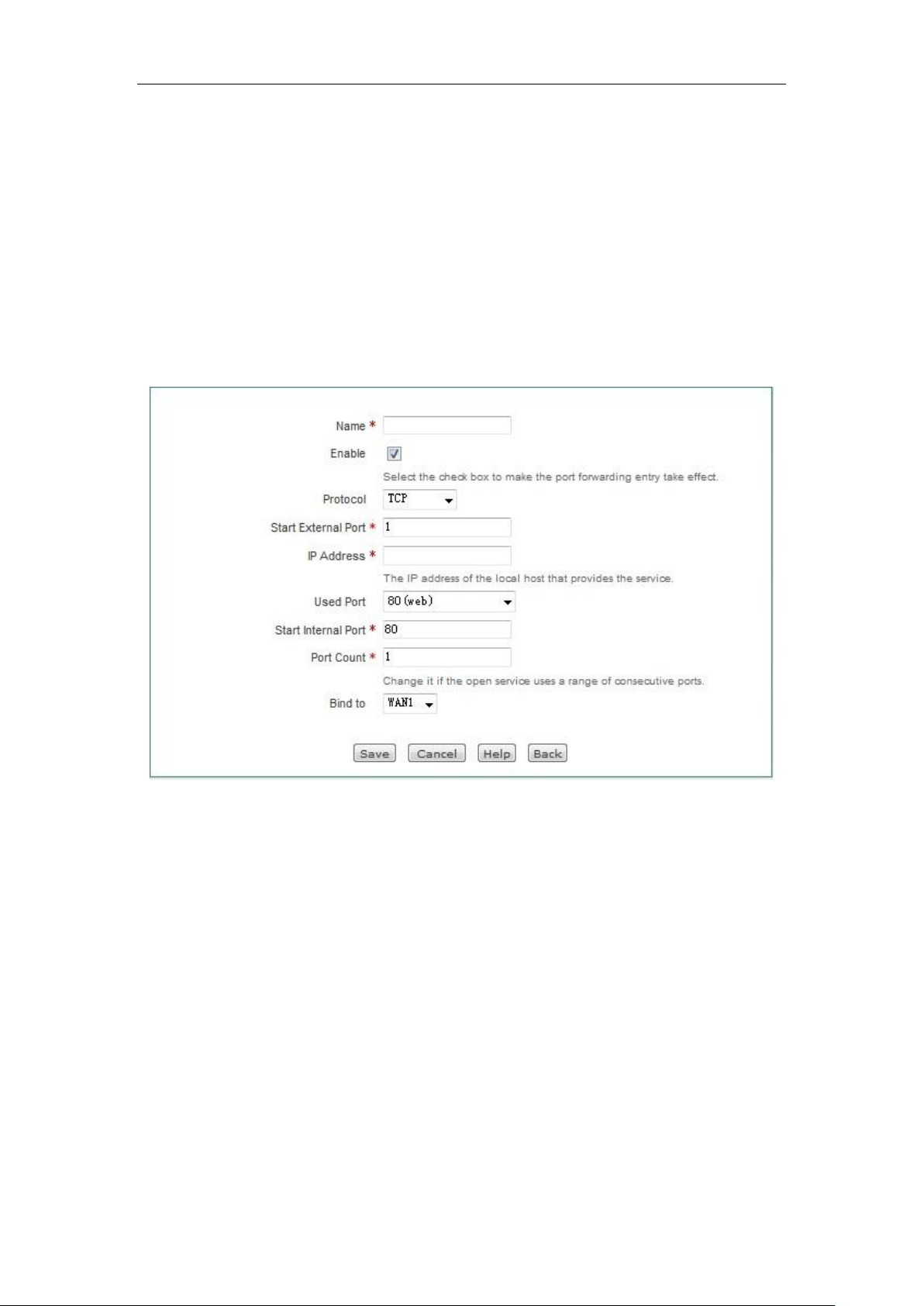
Chapter 8 Wireless configuration
8.1.5 NAT and DMZ configuration instances
This section describes the specific instances of NAT and DMZ configuration. Includes: Static
NAT mapping instances, instances with the type of NAT rules as EasyIP, One2One.
一、 Instances of Static NAT mapping configuration
Intranet computer 192.168.1.99 starts the TCP80 port services, and wants to access this service
through WAN1 port 80. It's configuration is as shown in Figure 8_7.
Figure 8_7 Port Forwarding Settings
二、 EasyIP configuration instances
An Internet café uses a single line for Internet access, and the ISP has assigned 8 addresses for this
line: 218.1.21.0/29 -218.1.21.7/29, where 218.1.21.1/29 is the gateway address of the line, and
218.1.21.2/29 is the IP address of WAN1 port of the device. Note that 218.1.21.0/29 and
218.1.21.7/29 are respectively the related subnet number and broadcast address, which cannot be
used.
Now, Game B Zone (IP address range: 192.168.1.10/24-192.168.1.100/24) wishes to use
218.1.21.3/29 as a NAT mapping address for accessing to the Internet through the WAN port.
Configuration steps are follows:
The first step is to enter the Advanced configuration -> NAT and DMZ configurations ->NAT
rules page, and click <Add new entry>.
The second step is to enter the NAT rules configuration page, and fill in "Game Zone" in the
http://www.level1.com Page 70
Page 71
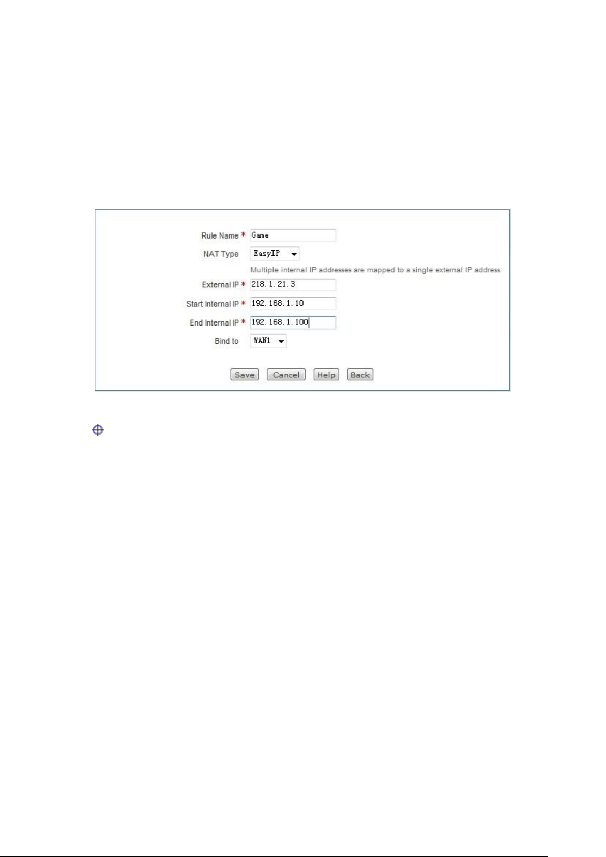
Chapter 8 Wireless configuration
"Rule name".
The third step is to select "NAT type" as "EasyIP".
The fourth step is to fill in 218.1.21.3 in the "External IP address". Fill in 192.168.1.10 and
192.168.1.100 in "Internal starting IP address" and "Internal ending IP address" respectively.
The fifth step is to select the rule-bound interface as WAN1 port.
The sixth step is to click <Save>, and the NAT rule is configured successfully.
Figure 8_8 NAT rules Settings——EasyIP
Tip:
When configuring Easy IP, if the "External IP address" is not on the same network segment as the
IP address of the bound interface, a route must be configured on the upper router to the network
segment on which the "External IP address" resides or a 32-bit host route to the "external IP
address", and the next hop is set to the IP address of the bound interface.
三、 One2One configuration instance
Demands
An enterprise applies for a line of Telecom, which adopts the fixed IP access method, and the
bandwidth is 6M. Telecom assigned 8 addresses to it: 202.1.1.128/29-202.1.1.1.135/29. Here,
202.1.1.129/29 is the gateway address of the line, and 202.1.1.130/29 is the IP address of the
device's WAN1. Note: 218.1.21.0/29 and 218.1.21.7/29 are respectively the related subnet number
and broadcast address, which cannot be used.
The company wants its people to access to the Internet via NAT by using 202.1.1.130/29 sharing.
Additionally, there are four servers that are in one-to-one NAT (One2One) and use
202.1.1.131/29-202.1.1.1.134/29 for providing services externally. The internal network address is
192.168.1.0/24, and the address for 4 servers is 192.168.1.200/24-192.168.1.203/24.
Analysis
Since the fixed IP access mode is used for Internet access on this line, it is necessary to configure
http://www.level1.com Page 71
Page 72
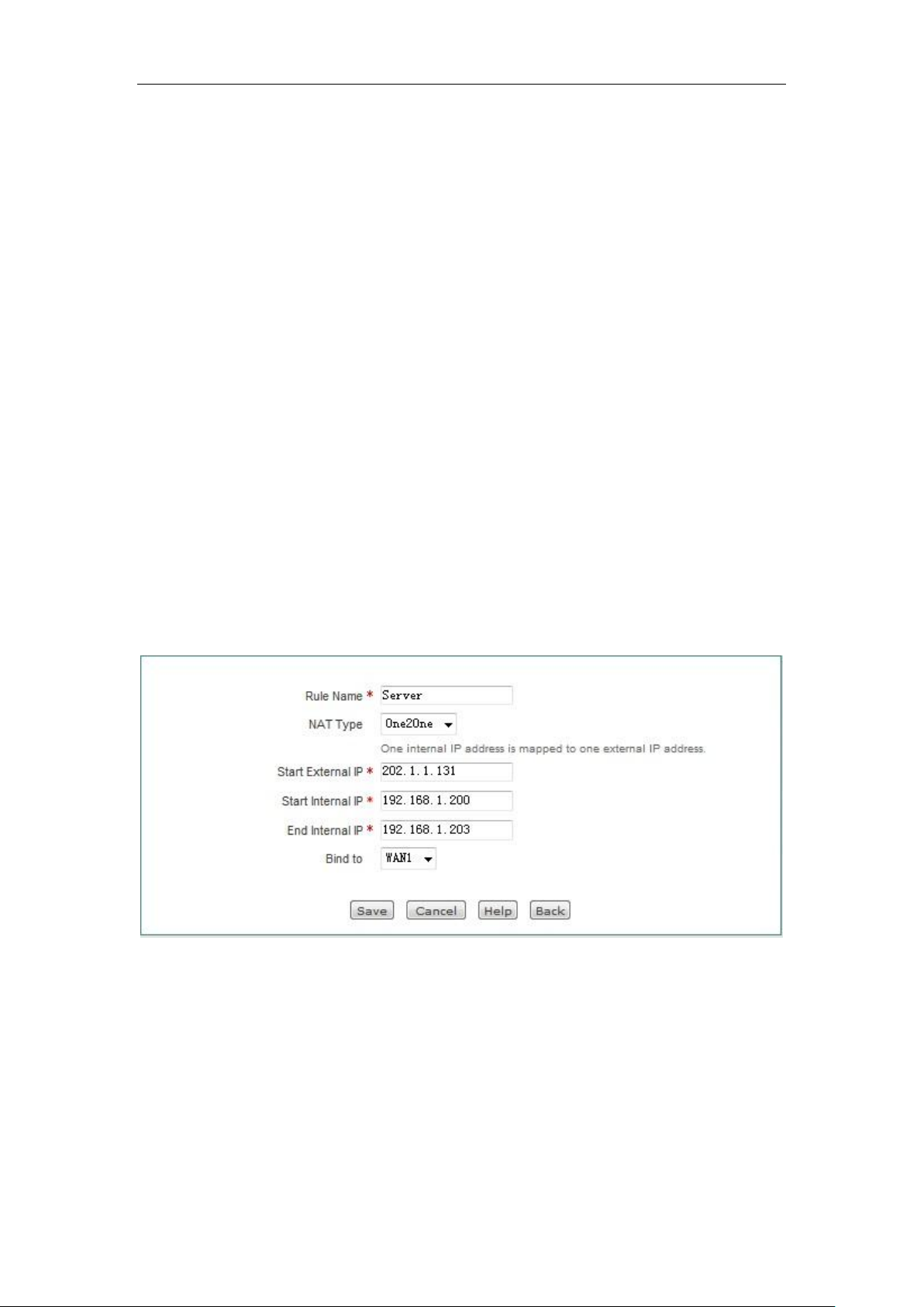
Chapter 8 Wireless configuration
the fixed IP access to the default Internet line in Network parameters —> WAN port
configuration page, or directly enter the Start--> Configuration wizard > Network parameter
spage to configure the line. After the default Internet access line is configured correctly, the
system-reserved NAT rules corresponding to the default line will be automatically generated, and
the NAT function is automatically enabled.
And this enterprise provides four internal servers for external access, so it is also necessary to set
an NAT rule with the type of "One2One".
Configuration steps are follows:
The first step is to enter the Advanced configuration -> NAT and DMZ configurations ->NAT
rules page, and click <Add new entry>.
The second step is to enter the NAT rules configuration page, and fill in "Server" in the "Rule
name".
The third step is to select "NAT type" as "One2One".
The fourth step is to fill in202.1.1.131in the "External starting IP address". Fill
in192.168.1.200and 192.168.1.203 in "Internal starting IP address" and "Internal ending IP
address" respectively.
The fifth step is to select the rule-bound interface as WAN1 port.
The sixth step is to click <Save>, and the NAT rule is configured successfully.
Figure 8_9 NAT rule Settings —One2One
8.2 Static Route Settings
This section describes the Advanced Configuration-> Routing configuration page and
configuration methods.
http://www.level1.com Page 72
Page 73
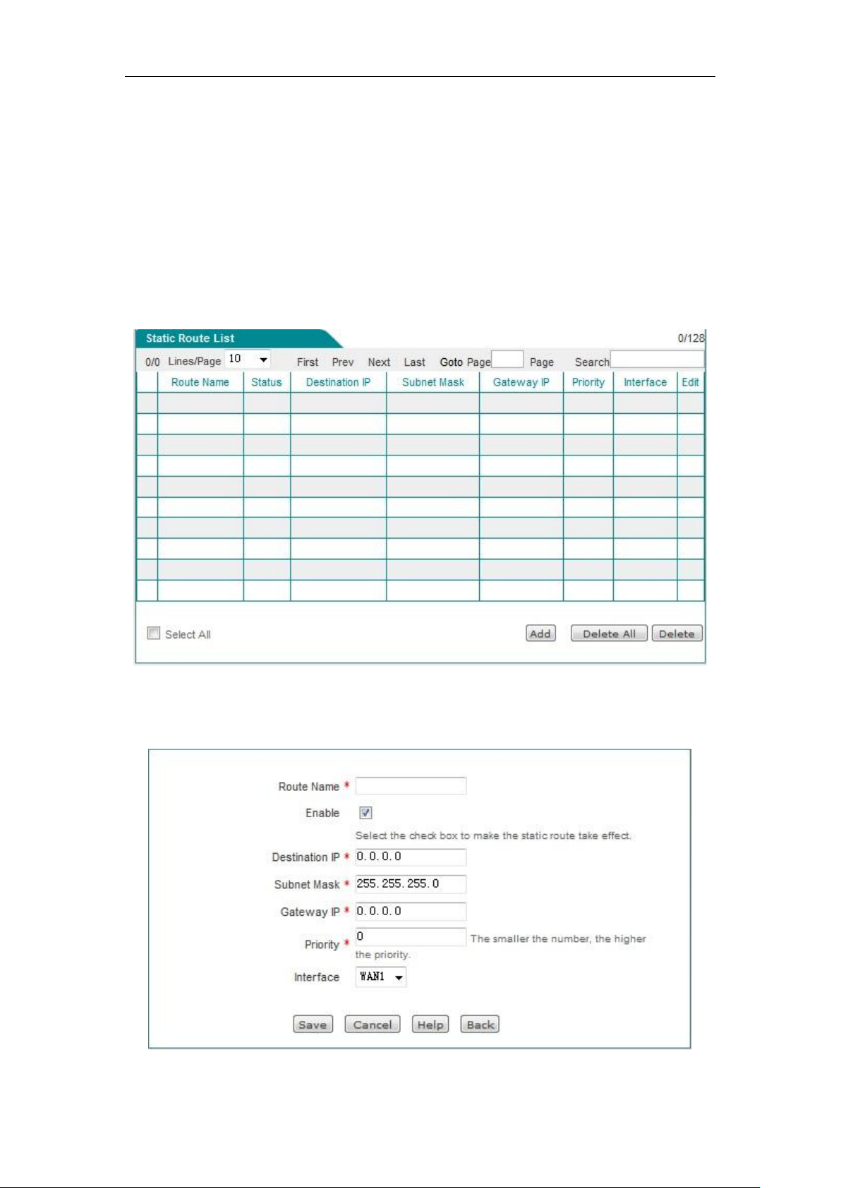
Chapter 8 Wireless configuration
Static route is manually configured by a network administrator, making the transmission of
packets to the specified destination network be realized according to the predetermined path.
Static routing does not change with changes in the structure of the network, therefore, when
network structure changes or there is a network failure, you need to manually modify the static
routing information in the routing table. Setting and using static routes correctly can improve
network performance and meet special requirements, such as implementing traffic control,
guaranteeing bandwidth for important applications and so on.
The following describes the list of routing configuration information and the meaning of the
parameters in the routing configuration.
Figure 8_10 Static Route List
Click <Add new entry> in the above figure, and enter the Route configuration page.
Figure 8_11 Static Route Settings
http://www.level1.com Page 73
Page 74

Chapter 8 Wireless configuration
Routing name: The name of static routes (custom, no repetition).
Enable this configuration: Enables this static route. Selecting it means enabled, while
deselecting it means the route is disabled.
Destination network: The destination network number for this static route.
Subnet mask: The mask of the destination network for this static route.
Gateway address: The IP address of the next-hop router ingress. The device defines a line for
hopping to the next router through interface and gateway. Typically, the interface address and
the gateway must be on the same network segment.
Priority: Sets the priority of a static route. When the destination network, subnet mask are the
same, select the high priority routing for forwarding data, and the smaller the value is, the
higher the priority is.
Interface: The forwarding interface for the specified packets. The packets matching the static
route will be forwarded from the specified interface.
Tip:
When the destination network and priority of multiple routes are the same, the device will match
them in the principle of first matching for last establishment.
8.3 Policy routing
This section mainly describes Advanced Configuration—>Policy routing page and configuration
methods. In this page, you can define policy routing, and the packet are routed according to the
source IP addresses, protocols, destination addresses and destination ports.
http://www.level1.com Page 74
Page 75
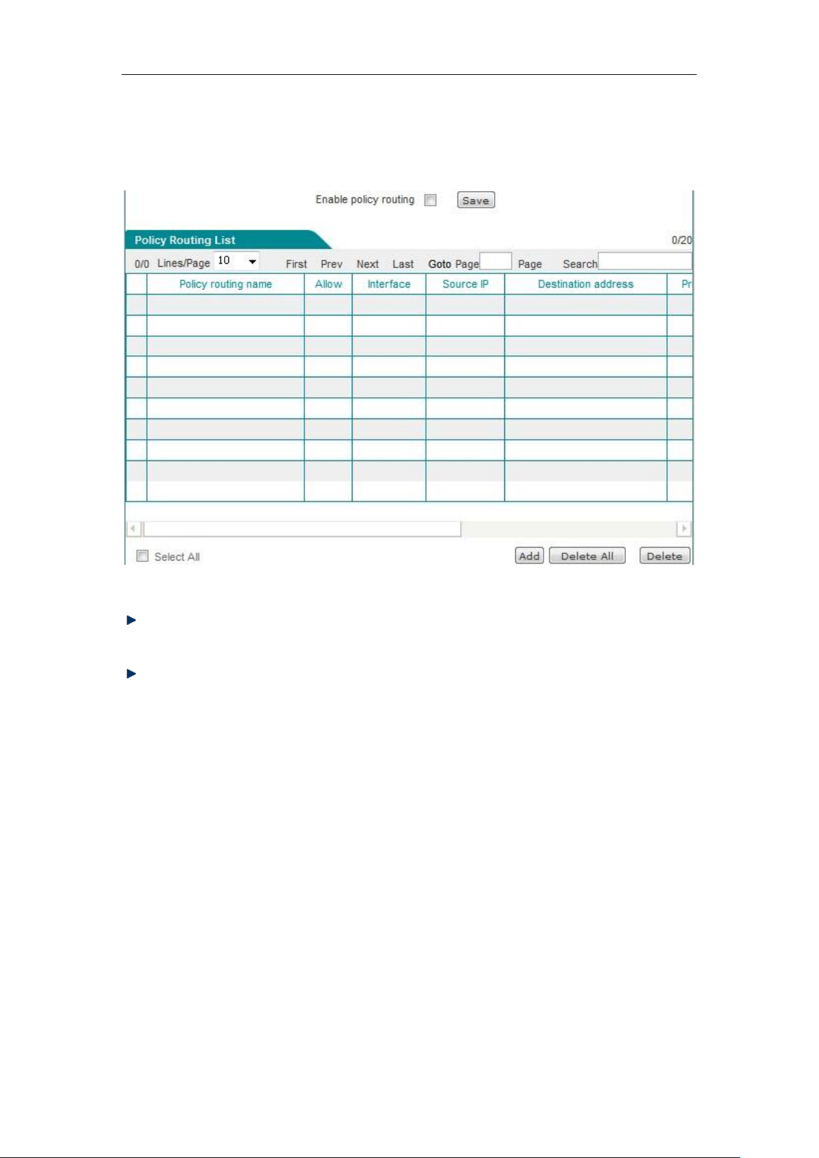
Chapter 8 Wireless configuration
8.3.1 Enable policy routing
Figure 8_12 Policy routing list
Enable policy routing: This is a global switch of policy routing. Only after it is enabled can
the configured policy routing can take effect.
Move to: Users can appropriately sort the policies using this bLeveloneon.
8.3.2 Policy routing configuration
Click <Add new entry> in the above figure, and enter the Policy routing configuration page.
http://www.level1.com Page 75
Page 76
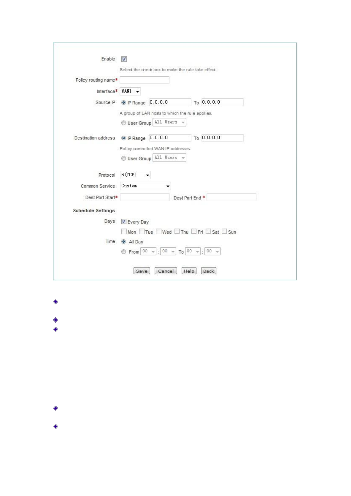
Chapter 8 Wireless configuration
Figure 8_13 Policy routing configuration
Interface: Sets the physical interface bound by the policy routing, and the packets that meet
the conditions of policy routing will be forwarded from the bound interface.
Policy route name: Customizes the name of the policy.
Source address: The source IP address of the packets following this policy route, which can
be configured in two ways.
Network segment: The starting IP address and the ending IP address following this
policy route.
User group: The user group following this policy route, click on "User group" to refer to
the source address for policy reference for the user group. Enter User management ->
User group configuration-> Add new entry to set up the source address field for the
policy routing to take effect.
Destination address: The destination address in the packet following this policy route, which
is configured in the same way as the source address.
Services: The services in the packets following this policy route, which can be configured in
the following manner.
Ports: Range 1-65535, the corresponding protocols are TCP and UDP; when the selected
http://www.level1.com Page 76
Page 77

Chapter 8 Wireless configuration
protocol is ICMP, the port range needs not be configured.
Effective time setting: Selects the time period for the policy routing takes effect, and the
default date is "Every day". The time is "All day". You can go to Advanced settings —>
Configure policy route page to edit the time for the policy route to take effect.
Tip:
1. When all the packets match the defined source IP address, protocol and destination port,
they will be forwarded to the specified interface, but the packets that cannot find a
matching policy routes will go the normal route.
2. The execution order of policy routing: Static route to the LAN port > Policy routing >
Static route to the WAN port.
8.4 Anti-NetSniper
This section describes the Advanced Configuration -> Anti-NetSniper page and configuration
methods. Network vanguard defense is used to crack the shared detection set by the network
operator. Verify that the intranet is experiencing a sharing problem, or don't enable that function.
Figure 8_14 Anti-NetSniper
8.5 Port mirroring
This section describes the port mirroring function of the Advanced configuration -> Port
mirroring page. With the port mirroring function, you can copy the flow of the monitoring port to
the monitoring port, to provide the detailed information on the transmitting status of the monitored
ports, allowing network managers to make traffic monitoring, performance analysis and
troubleshooting.
Except HiPER
the default LAN1 port of monitoring port, and other LAN ports are monitored ports. The
TM
840G, the devices of HiPER series that support the port mirroring function have
http://www.level1.com Page 77
Page 78

Chapter 8 Wireless configuration
configuration interface is shown in the figure below.
Figure 8_15 Port mirroring
Enable mirroring: Checking it to enable this feature.
When the HiPER
work.
Monitoring port: The port for monitoring the traffic of the monitored ports, which can be
only one.
Monitored port: Only one monitored port can be selected.
TM
840G device supports two or more LAN ports, the port mirroring function can
Tip: The monitored port cannot be the same port as the monitoring port.
8.6 Port VLAN
This section describes the port VLAN function of the Advanced configuration -> Port VLAN
page.
VLAN (virtual LAN) can split the network into several different broadcast domains logically. A
logical constitutes a logical broadcast domain. The members of the same VLAN share broadcast
and can communicate with each other. To achieve physical isolation between different VLANs,
the unicast, broadcast and multicast packets within a VLAN will not be forwarded to any other
VLAN, thereby helping to control traffic, simplify network management and enhance network
security.
3. Port VLAN list
http://www.level1.com Page 78
Page 79
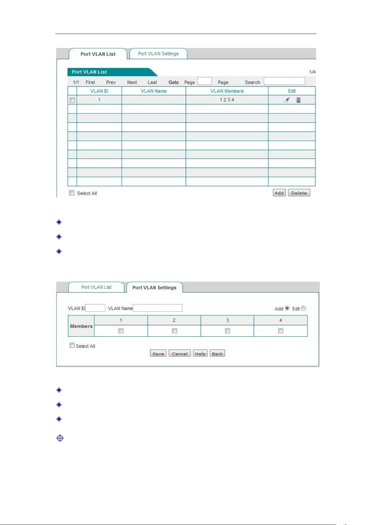
Chapter 8 Wireless configuration
Figure 8_16 Port VLAN list
VLAN group number: Displays the VLAN group number of the VLAN.
VLAN group name: Displays the VLAN group name of the VLAN.
VLAN members: Displays the members to the VLAN.
4. Port VLAN
Figure 8_17 Port VLAN settings
VLAN group number: Sets the VLAN group number.
VLAN group name: Sets the name of the VLAN group.
VLAN members: Selects the members to the VLAN group.
Tip:
1. The system has a default VLAN (VLAN 1), and it contains all physical ports by default, and
cannot be deleted.
http://www.level1.com Page 79
Page 80
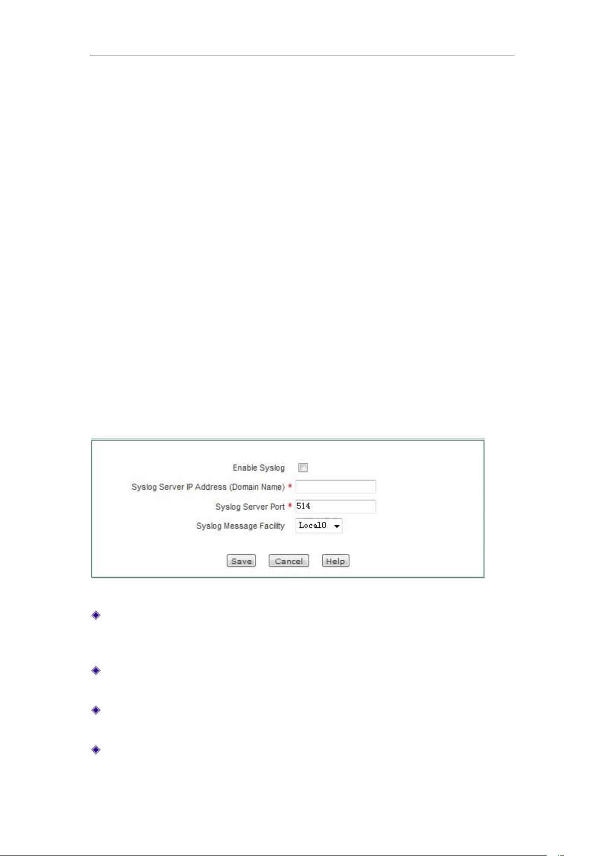
Chapter 8 Wireless configuration
2. A VLAN can contain more than one port, and one port can belong to more than one VLAN.
5. Instances of Port VLAN
Requirements: The host under the LAN1 port can communicate with the hosts under the LAN2,
LAN3 ports, but those under the LAN2 and LAN3 ports cannot access to each other.
Configuration steps:
1. Modify VLAN 1, whose member ports only include: 1, 2.
2. Create VLAN 2, whose member ports are: 1, 3.
Analysis: Both LAN1 port and LAN2 port belong to VLAN1, both LAN1 and LAN3 belong to
VLAN2; the hosts under the fixed LAN1 port can communicate with the hosts under LAN2,
LAN3 ports. Additionally, both LAN2 port and LAN3 port are not in the same VLAN, and the
hosts under LAN2 and LAN3 cannot access to each other.
8.7 SYSLOG configuration
This section describes the Advanced Configuration -> SYSLOG configuration page.
Figure 8_18 SYSLOG configuration
Enable Syslog service: After the syslog service feature is enabled, this feature will send a
large amount of information of device operation to a syslog server, which makes it easy for
administrators to analyze system conditions, and monitoring system activity.
Address of syslog server (domain name): Sets the address of the syslog server, which can be
an IP address or a domain name.
Port of Syslog server: Sets the service ports that are opened by the syslog server, whose
default value is 514.
Syslog message type: Sets the type of syslog message to be sent, whose default value is
Local0.
http://www.level1.com Page 80
Page 81
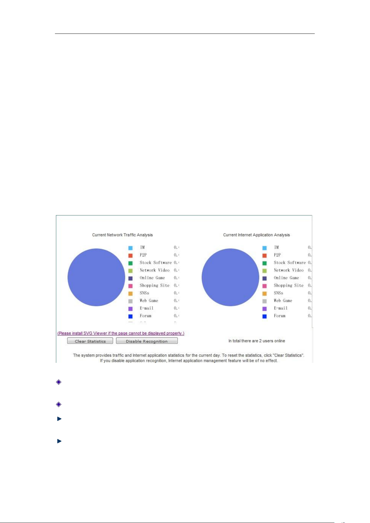
Chapter 9 Wireless configuration
Chapter 9. User management
This chapter describes the secondary menu under the primary menu of user management,
including: User state, IP/MAC binding, PPPoE server, WEB authentication, user group
configuration.
9.1 User status
This section describes the User management-> User status page. Administrators can understand
all intranet users' net behaviors, the traffic occupied by the net behaviors and the status of each
user, and so on by viewing, analyzing the pie charts and lists in this page.
Figure 9_1 User Status
Analysis of the current network traffic usage: analyzes the current percentage of network
traffic used by Intranet applications.
Analysis of current net behaviors: Analyzes the net behavior of all currently online users.
Clear data: The system counts the traffic and net behaviors from 00:00 every day. Clicking
this bLeveloneon will clear the historical data of the day and immediately begin to recount.
Disable identification statistics: Click this bLeveloneon to disable the identification function
for net behavior management. After doing this, the net behavior management function will be
disabled.
http://www.level1.com Page 81
Page 82
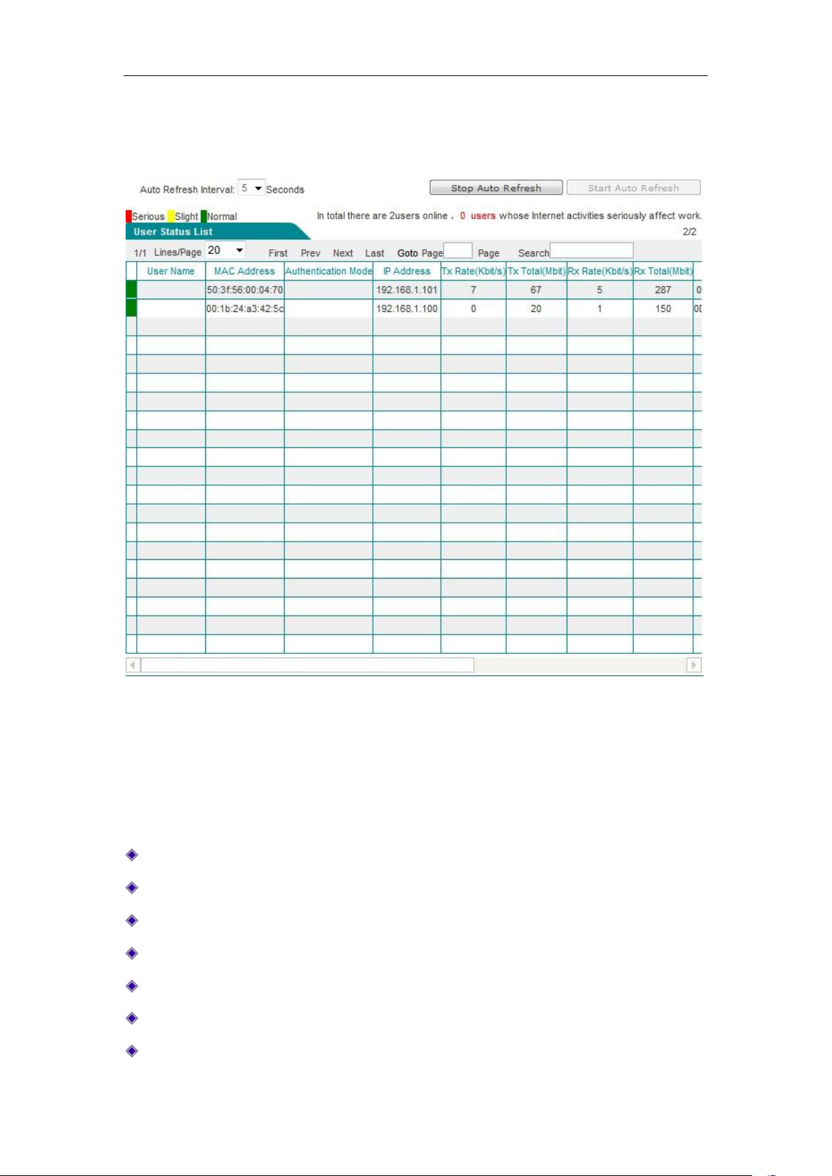
Chapter 9 Wireless configuration
The following describes the list of user status information, through checking of which,
administrators can learn about each online user's online time, real-time upload/download rate, total
uplink/downlink traffic, net behaviors, etc.
Figure 9_2 User status information list
The first column of user status information displays if each user's net behaviors are affecting work,
whose status includes: Severe (red), minor (yellow), normal (green). When an intranet user's
behavior of accessing shopping websites, social networking sites, using stock software and
playing online/web game accounts for a range of [100%, 70%] of all of its personal net behaviors,
this means seriously affecting work. When the range is (70%, 50%), it means minor. When the
range is (50%, 0%), it means normal.
User name: Displays the user name for Intranet users.
MAC address: Displays the MAC address of Intranet users.
Ways of authentication: Displays authentication of Intranet users (WEB and PPPoE)
IP address: Displays the IP address of Intranet users.
Upload, download rate: Displays the upload and download rate of Intranet users.
Total uplink, downlink traffic: Displays the total uplink and downlink traffic of Intranet users.
Online time: Displays the user's online time.
http://www.level1.com Page 82
Page 83

Chapter 9 Wireless configuration
Group: Displays the group to which the user belongs.
Net behavior: Displays the user's net behaviors.
Settings: Click the icon. If you want to clear the user's net behavior statistics, please click
"Clear data".
Note: Click on the icon to modify the description information of PPPoE dial-up user, WEB
authenticated user.
Automatic refreshing interval: This list supports automatic refreshing, with the interval of 1-5
seconds.
Stop automatic refreshing: Click this bLeveloneon and the list will stop automatic refreshing.
If you need to view the information of the entire list or modify the notes, etc., it is proposed
to stop automatic refreshing.
Start automatic refreshing: Click this bLeveloneon and the list will refresh the list at the
automatic refreshing interval.
9.2 IP/MAC binding
This section describes the User management->IP/MAC binding page and configuration method.
To implement network security management, you must first solve the identity problems of users
before you can carry out the necessary service authorization work. In Firewall -> Access control
policy, we will introduce how to implement the control of Intranet users' net behaviors. In this
section, we will describe how to solve the problem of user identification.
In the device, user's identification can be completed through the IP/MAC binding function. The
use of the bound IP/MAC address pair as the user's unique identity ID can protect the device and
network against IP spoofing attacks. IP spoofing attack means that a host attempts to use another
trusted host's IP address to connect to the device or pass through the device. This host's IP address
can be easily changed as a trusted IP address, but the MAC address is added by the manufacturer
to the Ethernet card, so it cannot be easily changed.
http://www.level1.com Page 83
Page 84
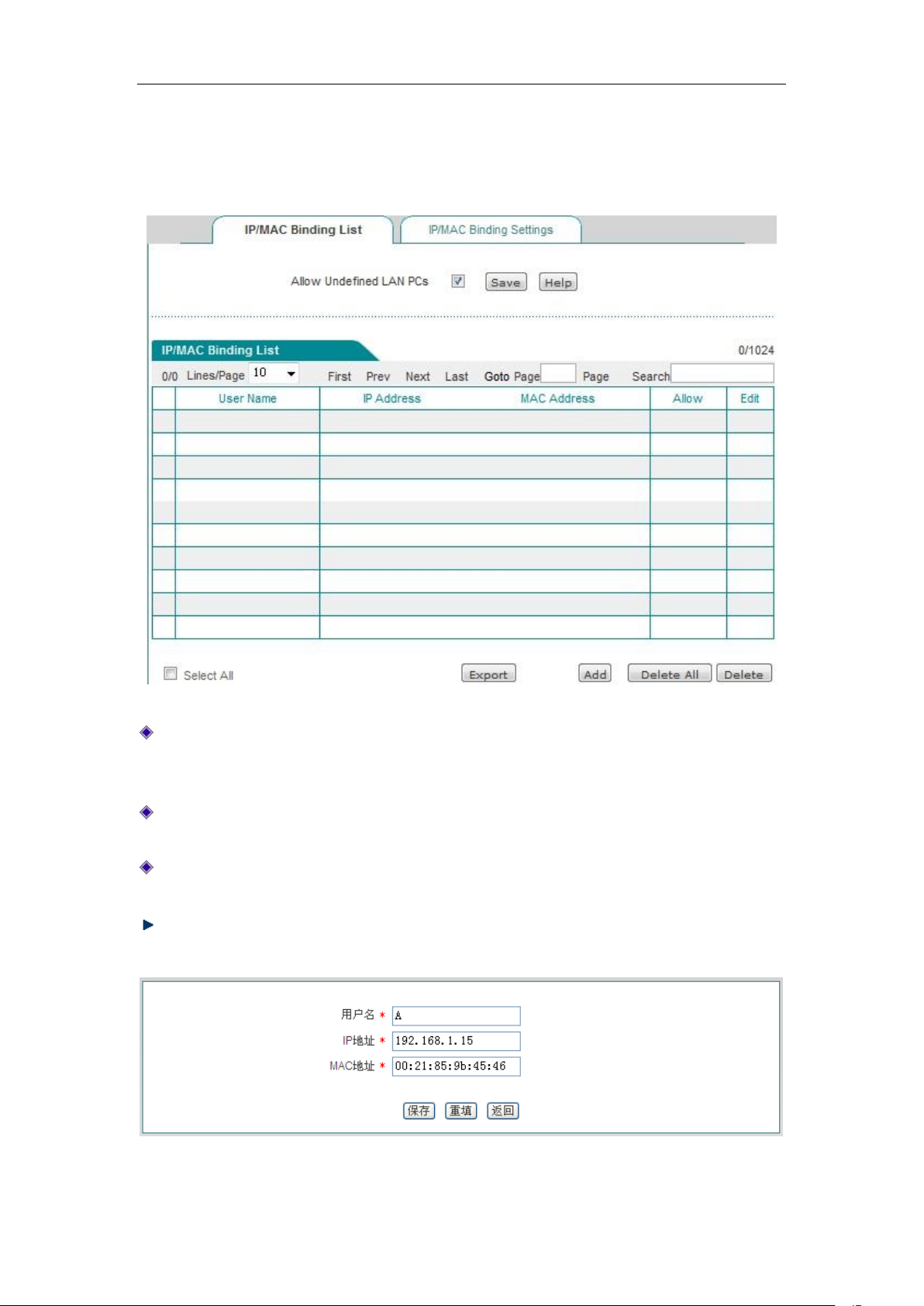
Chapter 9 Wireless configuration
9.2.1 IP/MAC binding list
Figure 9_3 IP/MAC binding global configuration
Allow non-IP/MAC bound user to connect to the device: Allows or disallows the
non-IP/MAC bound users to connect to the device, and access to other networks through the
device.
Allow: Ticking this check box means to allow the bound user to connect to the device, but
unchecking it means to disallow the bound user to connect to the device.
Modify the IP/MAC binding entries, click the Edit icon, to enter the IP/MAC binding
configuration page as shown in the figure below, and after change, click <Save>.
Export: This bLeveloneon is used to export the IP address, MAC address, user name in the
list of IP/MAC binding information.
Figure 9_4 Modification of IP/MAC instances
http://www.level1.com Page 84
Page 85
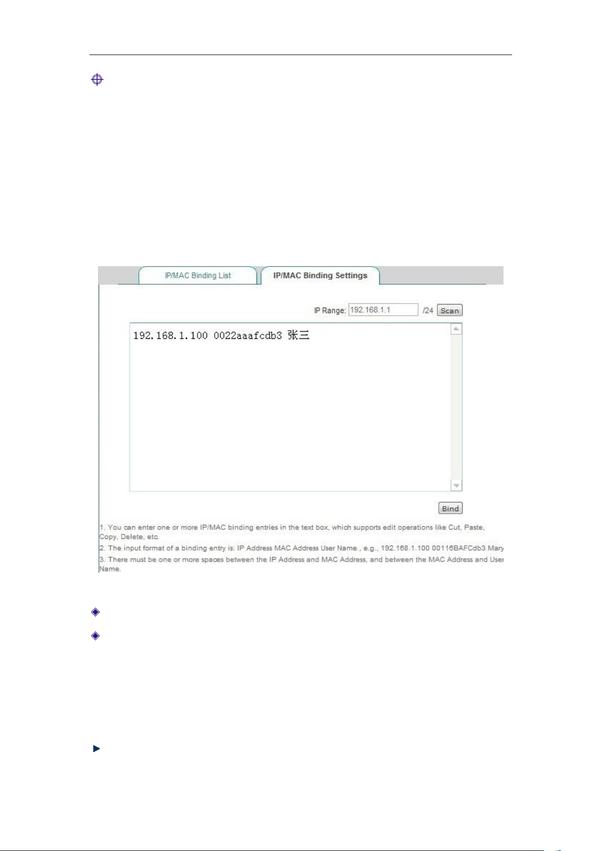
Chapter 9 Wireless configuration
Tip:
Before deciding to cancel the "Allow non-IP/MAC bound user to connect to the device" function,
you must make sure that the management computer has been added to the "IP/MAC binding
information list", otherwise it will cause the management computer to be unable to connect to the
device.
9.2.2 IP/MAC binding configuration
Figure 9_5 IP/MAC binding configuration
Network segment: The management IP address/subnet mask of the device by default.
Text box: Displays the scanned IP/MAC information, or the configured IP/MAC binding
information, whose input format is "IP+MAC+ username".
IP address, MAC address: The user's IP address, MAC address (which can be obtained
using the ipconfig /all command under DOS environment on Windows platforms).
User name: It can be ignored, because the system will automatically assign a name for
it.
Scan: Click <Scan> to display the ARP information dynamically learned by the device.
http://www.level1.com Page 85
Page 86

Chapter 9 Wireless configuration
Binding: Binds all the IP/MAC entries in the text box.
Tip:
1. In the above input format, there may be one or more spaces between the IP and MAC, MAC
and username.
2. For the invalid entries, the system will skip the invalid configuration entries in binding.
9.2.3 IP/MAC binding instances
Flexibly using the IP/MAC binding feature can configure "white list" and "black list" for Internet
access for Intranet users.
By configuring the "white list" for Internet access, only the users in "white list" are allowed to
access the Internet through the device, while prohibiting all other users from doing it. Therefore, if
only a few users in the intranet are allowed for accessing the Internet, a "white list" is to be
configured to achieve this goal.
By configuring the "black list" for Internet access, only the users in "black list" are prohibited
from accessing the Internet through the device, while allowing all other users to do it. Therefore, if
only a few users in the intranet are prohibited from accessing the Internet, a "black list" is to be
configured to achieve this goal.
In the device, the users in the "white list" are legal users - their IP and MAC address exactly
matches an entry in the "IP/MAC binding information list", and the entry selects "Allow".
The users in the "black list" are illegal users - their IP and MAC address exactly matches an entry
in the "IP/MAC binding information list", and the entry does not select "Allow". Or, there is only
one entry in their IP and MAC address matches the corresponding information of a bound entry.
1. Configure "white list" of Internet access for Intranet users, following these steps:
First, Specify legal users by configuring the IP/MAC binding entries, and use the IP address and
MAC address of the host with the permission to access the Internet as the IP/MAC address
binding pair, and add it to the "IP/MAC-binding information list", and "Allow" needs also be
selected, that is, allow the users exactly matching the IP/MAC address to access the Internet.
Next, deselect the "Allow non-IP/MAC binding user to connect to the device", so that all other
hosts not included in the "IP/MAC binding information list" will not be able to access the Internet.
For example, if you want to allow a host with the IP address of 192.168.1.2, and the MAC address
of0021859b4544to connect to and pass the device, you can add an IP/MAC address binding entry,
enter the host's IP address and MAC address, and select "Allow", as shown in Figure 9_ 6 .
http://www.level1.com Page 86
Page 87
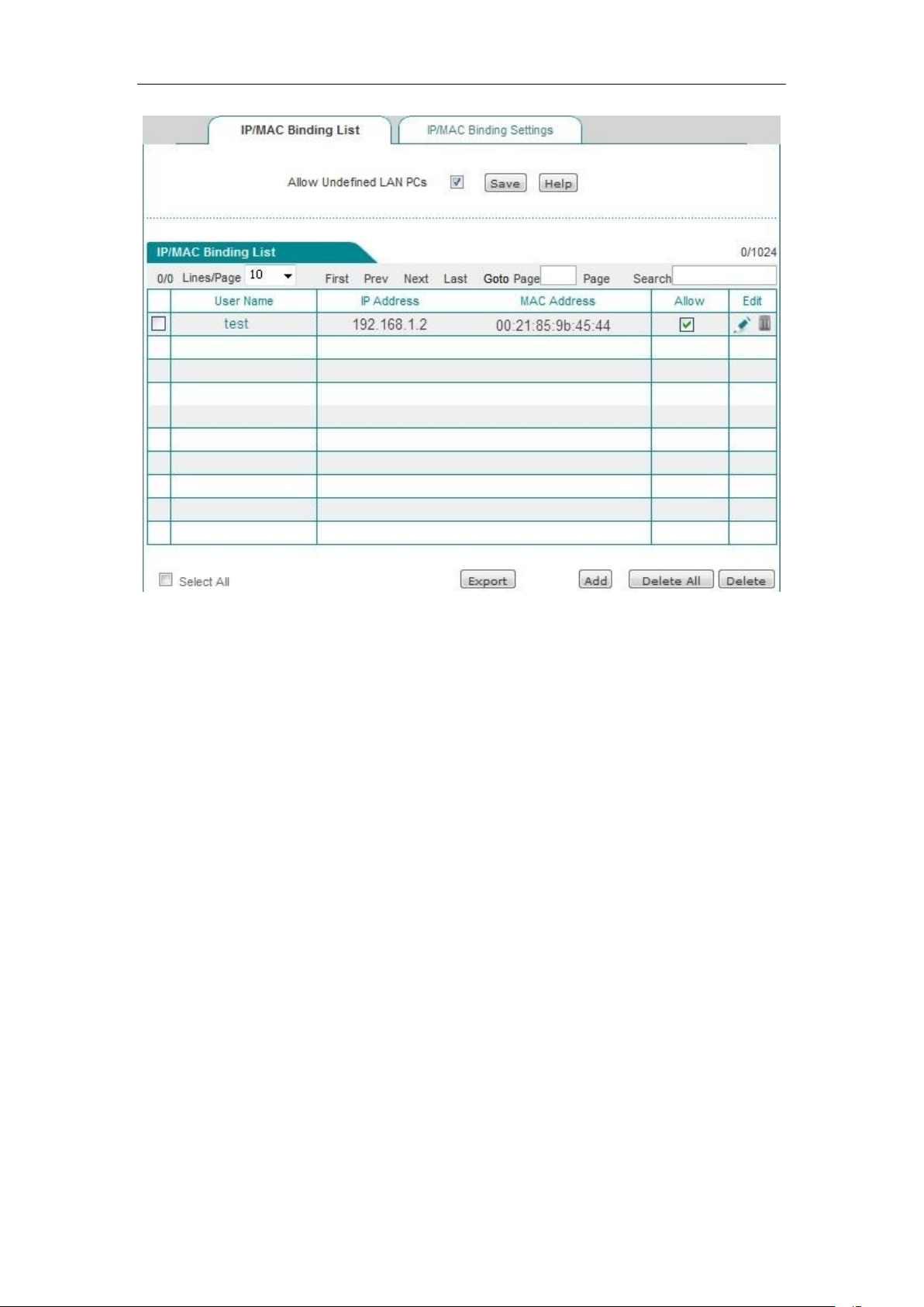
Chapter 9 Wireless configuration
Figure 9_6 IP/MAC binding information list – Instance I
2. Configure "Black list" of Internet access for intranet users, following these steps:
First, specify the illegal user by configuring the IP/MAC binding entries, and there are two
methods:
1. Use the IP address of the host that is prohibited from Internet access and the MAC address of
any of the non-intranet adapter as the IP/MAC address binding pair, and add it into the
"IP/MAC-binding information list".
2. You can use the IP and MAC addresses of the host that is prohibited from Internet access as
the IP/MAC address binding pair, and deselect "Allow" (no "√" in the box), namely, to
prohibit the users that exactly match the IP/MAC address from accessing to the Internet.
Next, select the "Allow non-IP/MAC binding user to connect to the device", so that all other hosts
whose IP addresses and MAC addresses are not included in the "IP/MAC binding information list"
will be able to access the Internet.
For example, if you want to prohibit a host with the IP address (for example, 192.168.1.3) from
accessing and connecting to the device, you can add a IP/MAC address binding pair, enter the IP
address, and the MAC address is set to the MAC address of any non- intranet adapter, as shown in
the table below.
http://www.level1.com Page 87
Page 88
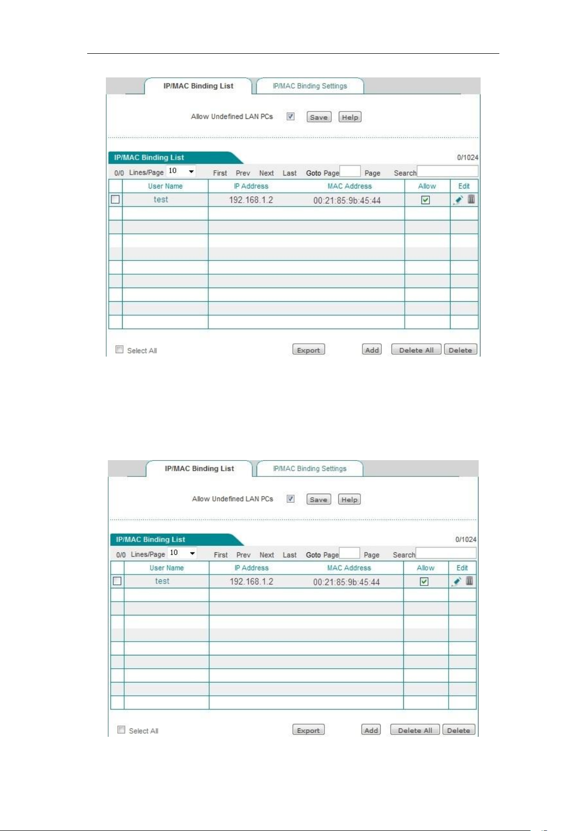
Chapter 9 Wireless configuration
Figure 9_7 IP/MAC binding information list – Instance II
For example, if you want to prohibit a host with the IP address of 192.168.1.30 and the MAC
address of 0021859b2564 from connecting and passing the device, you can add an IP/MAC
address binding pair, enter the host's IP address and MAC address, and deselect "Allow" (no "√"
in the box), as shown in Figure 9_ 8 .
Figure 9_8 IP/MAC binding information list – Instance III
http://www.level1.com Page 88
Page 89
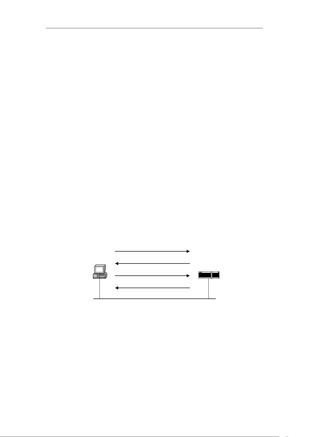
Chapter 9 Wireless configuration
PPPoE Client
PPPoE Server
PADI
PADO
PADR
PADS
9.3 PPPoE Server
This section describes the device's PPPoE function, including: PPPoE introduction, PPPoE global
configuration of device, configuration of PPPoE accounts and viewing of PPPoE connection
status.
9.3.1 PPPoE introduction
PPPoE (Point-to-Point Protocol over Ethernet). It allows a host on the Ethernet to connect to the
Internet through a simple access device. PPPoE protocol uses Client/Server, which encapsulates
PPP packets in an Ethernet frame, and provides the point-to-point connection over Ethernet.
PPPoE dial-up connections include two stages, Discovery (discovery) and Session (PPP session).
The following will introduce these two stages.
1. Discovery stage
This stage is used to establish a connection. When a user host wants to start a PPPoE session, it
must first implement the discovery stage to identify the Ethernet MAC address of PPPoE Server,
and establish a PPPoE session ID (Session ID).
Figure 9_9 Basic workflow of Discovery stage
As shown in the figure above, Discovery stage consists of four steps. The following describes the
basic workflow.
PADI: If you want to set up a PPPoE connection, PPPoE client should first send a PADI
(PPPoE Active Discovery Initiation) packet as a broadcast. The PADI packet includes the
services the client requests.
PADO: When the PPPoE server receives a PADI packet, it will determine if it is able to
provide services, and if so, it will send to the client a PADO (PPPoE Active Discovery Offer)
packet to respond. PADO packets include the PPPoE server name and the service name
http://www.level1.com Page 89
Page 90

Chapter 9 Wireless configuration
same as that in the PADI packet. If the PPPoE server cannot provide services to PADI, it is
not allowed to use the PADO packet to respond.
PADR: Since PADI is sent as a broadcast, the PPPoE client may receive more than one
PADO packet, and it will review all the PADO packets received and choose a PPPoE server
based on the server name in it or the services provided, and then send a PADR (PPPoE Active
Discovery Request) packet to the selected server. PADR packet includes the services
requested by the client.
PADS: When PPPoE server receives the PADR packet sent by the client, it is ready to start a
PPPoE session, and creates a unique PPPoE session ID for PPPoE session, and sends to the
client a PADS (PPPoE Active Discovery Session-confirmation) package as a response.
When the discovery stage ends normally, both ends of the communication obtain the session ID
and their MAC addresses, and they define a PPPoE session together uniquely.
2. PPP session stage
When PPPoE enters the PPP session stage, the client and the server will conduct a standard PPP
negotiation, and after this, the data is sent over PPP encapsulation. The PPP packets are
encapsulated as the payload of PPPoE frame in an Ethernet frame, and sent to the peer end of the
PPPoE link. Session ID must be the ID determined in the Discovery stage, and remains unchanged
during the session. The MAC address must be that of the peer end.
At any time during the session stage, both PPPoE server and client can send PADT (PPPoE Active
Discovery Terminate) to each other, notifying the other side of ending the session. When receiving
PADT, it is not allowed to use the session to send the PPP traffic. After sending or receiving a
PADT packet, even the conventional PPP end packet is not allowed to be sent. Normally, both
parties of PPP communication end the PPPoE session using the PPP itself, but can end the session
using PADT if PPP cannot be used.
9.3.2 PPPoE global Settings
Enter User management->PPPoE server page to configure the PPPoE server function. The
configuration parameters are described as follows.
http://www.level1.com Page 90
Page 91
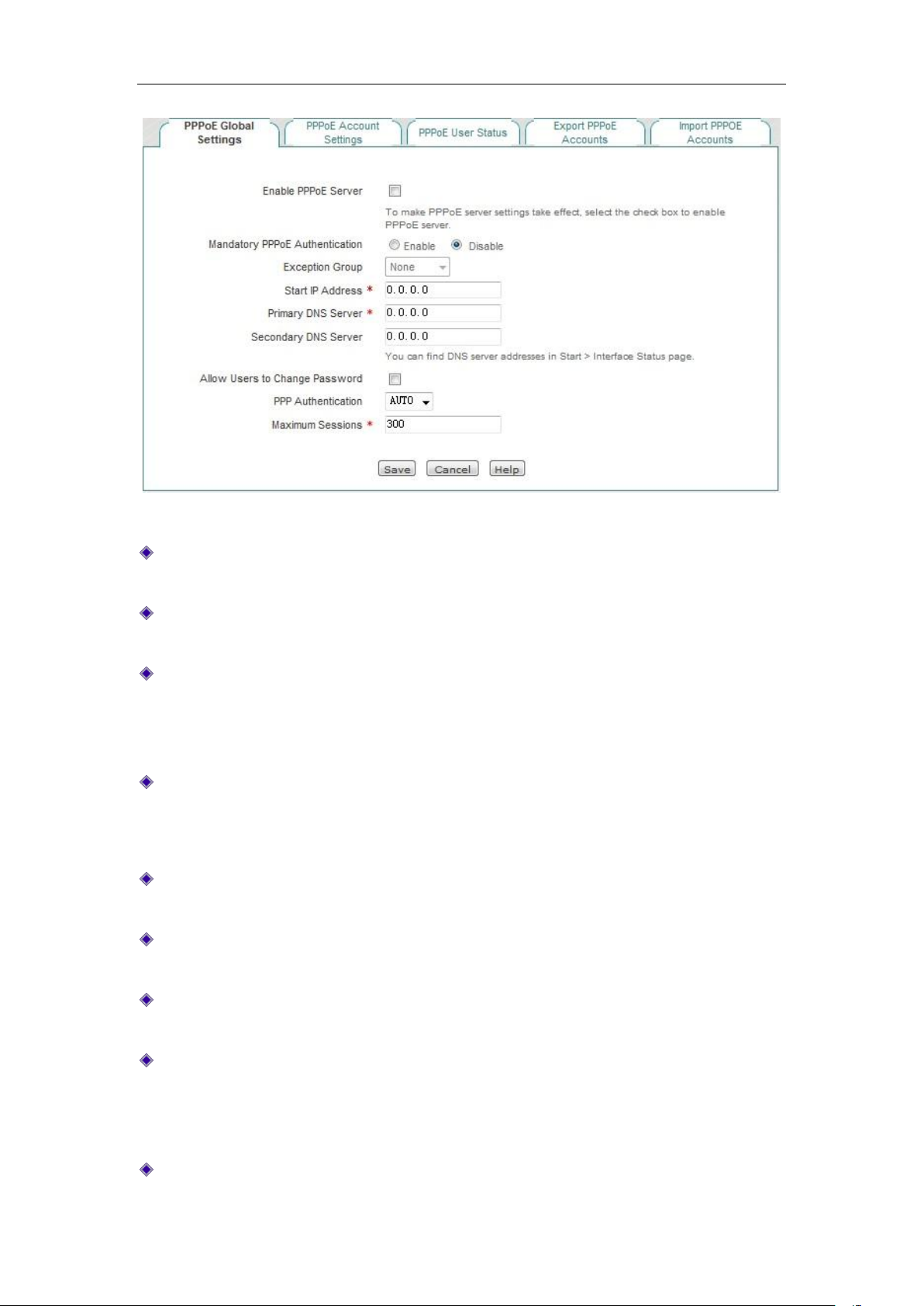
Chapter 9 Wireless configuration
Figure 9_10 PPPoE Global Settings
Enable PPPoE server: Enables/disables the PPPoE server function of the device. Select it to
enable.
Forcing PPPoE authentication: Enabling it means to only allow the users who pass the
intranet PPPoE authentication to access the Internet.
Exception address group: After the device enables the forcing PPPoE authentication, the
users of the address group can communicate with external network without dial-up
authentication, and the address group needs to be configured in the User management ->
User group configuration page.
Starting IP address: The starting IP address the PPPoE server automatically assigns to the
network computers.
Primary DNS server: The IP address of the primary DNS server automatically assigned by
the PPPoE server to the network computers.
Secondary DNS server: The IP address of the secondary DNS server automatically assigned
by the PPPoE server to the network computers.
Allow users to modify the dial-up password: Checking it means to allow intranet PPPoE
dial-up users to modify dial-up password on their own.
Password authentication mode: The way PPPoE authenticates username and password. The
device provides three authentication modes, PAP, CHAP and AUTO, and the default value is
AUTO, which means that the system automatically selects one of PAP and CHAP to
authenticate the dial-in users, and generally does not need to be set.
Maximum number of sessions: The maximum number of PPPoE sessions supported by the
http://www.level1.com Page 91
Page 92
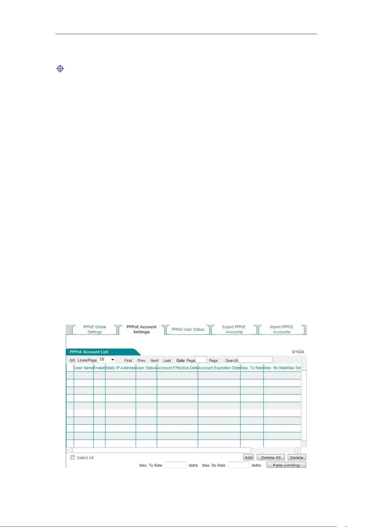
Chapter 9 Wireless configuration
system to be established.
Tip:
1. The steps that PPPoE users change the dial-up password:
1) Users open the dial-up client, and dial up using the user name, password.
2) After a successful dial-up, log into the self-service page, whose address is:
http://192.168.1.1/poeUsers.asp (the address is the LAN IP address for the device).
3) In the change password page, enter your user name, old password, new password, and
confirming password.
4) Click "Submit" to display "Operation is successful", and the password is successfully
changed.
2. Users can modify their password 5 times a day on their own.
3. The administrator can use the Behavior management -> Electronic notification page to
configure the Routine business notification for informing users of how to modify the
PPPoE dial-up password.
9.3.3 PPPoE account configuration
Enter the User management ->PPPoE account ->PPPoE server configuration page (as shown in
Figure 9_11) to view the PPPoE account info list. Click <Add new entry> in the page to enter into
the page as shown in Figure 9_ 12:
Figure 9_11 PPPoE account info list
http://www.level1.com Page 92
Page 93
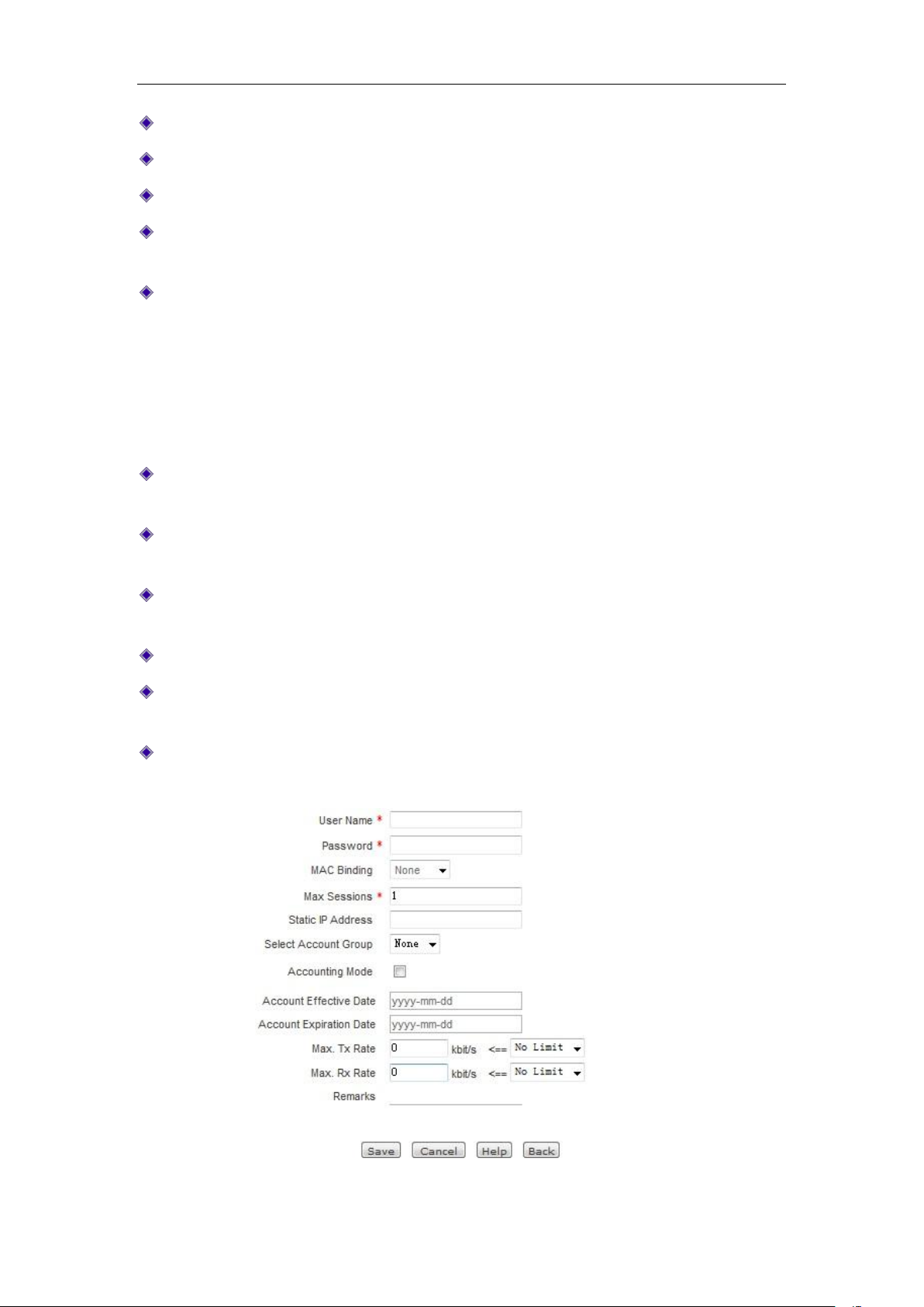
Chapter 9 Wireless configuration
User name: The user name of PPPoE dial-up users.
Enable: If the user is allowed to access the Internet. Checking it means allow.
Fixed IP address: Displays the IP address bound to that user name.
Charging mode: When the charging feature is enabled, the "by date" will be displayed (which
currently supports charged by date).
User status: The using status of the user will be displayed after the charging feature is
enabled, including: normal, to be expired, expired.
To be expired: This parameter is controlled through "Account Days Remaining" in the
account expiration notification feature (Here, the account expiration notification feature,
please go to Behavior management -> Electronic notification page for configuration).
Expired: Means that the account is not in the effective date of account.
Date of account opening, date of account disabling: When the charging feature is enabled, the
effective date of the account will be displayed.
Upload rate limit, download rate limit: The maximum upload and download rates of PPPOE
(0 means unlimited rate).
Maximum number of sessions for account: Displays the number of users who can
simultaneously use the account for PPPoE connection.
MAC address: Displays the MAC address bound by the account.
Upload rate limit, download rate limit: Sets rate limit in batch for the accounts checked in the
PPPoE account info list (0 means unlimited rate).
Rate limit: Click on this bLeveloneon, to bring the upload speed, download rate limit in
force.
Figure 9_12 PPPoE account settings
http://www.level1.com Page 93
Page 94

Chapter 9 Wireless configuration
User name: The account (custom, not repeatable) used by users in initiating PPPoE
connections for the PPPoE server to authenticate, the value range is: 1-31 characters.
Password: The password used by users in initiating PPPoE connections for the PPPoE server
to authenticate.
MAC binding: Chooses to bind the user name with the corresponding MAC address. If
binding, only the hosts with the corresponding MAC address can use the account for
accessing to the Internet.
No binding: Means no user name/MAC binding is to be done.
Automatic binding: After the user dials up successfully for the first time, the device will
automatically bind the user name with the dial-up user's MAC address.
Manual binding: Manually enters the MAC address in the MAC address bar for user
name/MAC binding.
Maximum number of sessions for account: Sets the number of users who can simultaneously
use the account for PPPoE connection.
Fixed IP address: The fixed IP address assigned for the PPPoE dial-up user, which must be
within the scope of address pool.
Added to the account groups: the user name will be added to the appropriate account group,
which must be configured in the User management -> User group configuration page.
Charging mode: Checking it means that the PPPoE charging feature is enabled. Here, the
account expiration notification feature is configured in the Behavior management ->
Electronic notification page.
Date of account opening, date of account disabling: Sets the effective date for the dial-up user
using the account.
Upload rate limit, download rate limit: The maximum upload and download rates of the
PPPOE account (0 means unlimited rate).
Note: Fill in the information to be noted. When Note Information is long, the page displays
only 5 characters, and when you position the mouse pointer over the content of the note, the
page will automatically display all the contents of the note.
Tip:
If the PPPoE account is configured with the upload and download rate, then the account will
no longer match the fine rate limit.
9.3.4 PPPoE user status
Enter the User management ->PPPoE server ->PPPoE user connection status page, on which
http://www.level1.com Page 94
Page 95
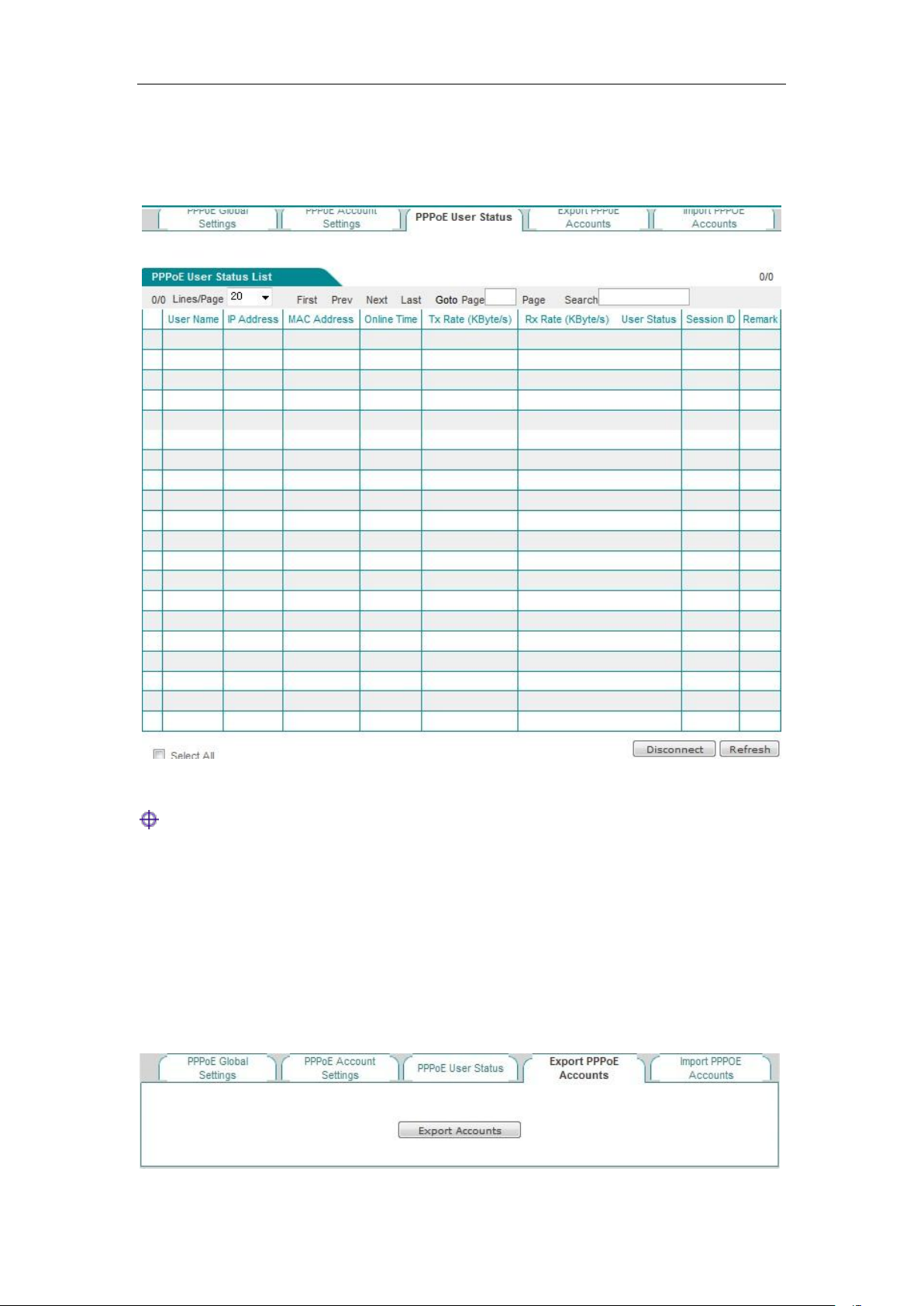
Chapter 9 Wireless configuration
you can view the account information used; if users use the configured user name to connect to the
PPPoE server, we can see such information of the IP addresses, the user's MAC address, online
time of PPPoE connections, upload/download rates, etc. the PPPoE server assigns to the user in
the list.
Figure 9_13 PPPoE User Status List
Tip:
When the account of the network dial-up user expires, dial-up can be made successfully, and the
user can access to the device, but cannot access the Internet.
9.3.5 Export PPPoE Accounts
http://www.level1.com Page 95
Page 96
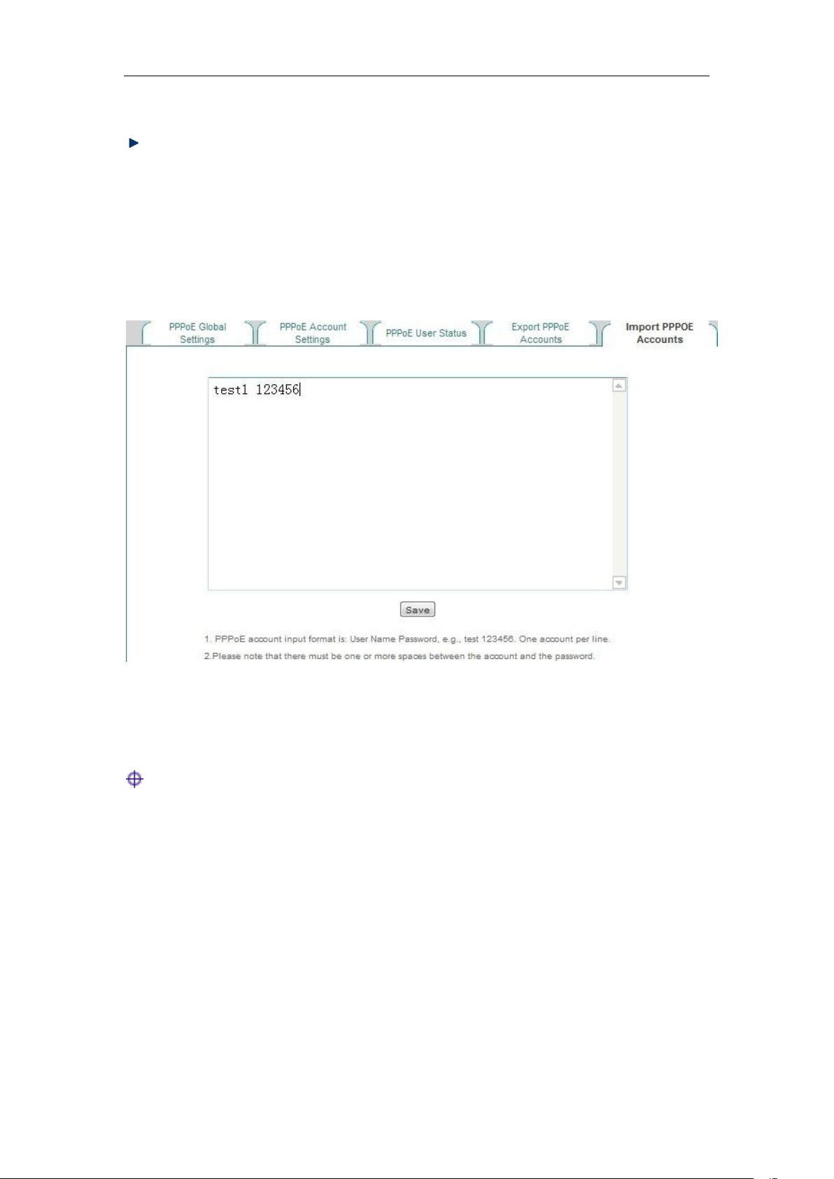
Chapter 9 Wireless configuration
Figure 9_14 Export PPPoE Accounts
Export account: Click this bLeveloneon to export all PPPoE accounts in the list, including the
user name, password for the account, in the. txt format.
9.3.6 Import PPPOE Accounts
Figure 9_15 Import PPPOE Accounts
Tip:
1. When configuring PPPOE accounts to be imported and bound in batch, its input format is
"Account + password", for example, test 123456, each row can have only one configuration
item entered.
2. In the above input format, there may be one or more spaces between the account and the
password.
http://www.level1.com Page 96
Page 97
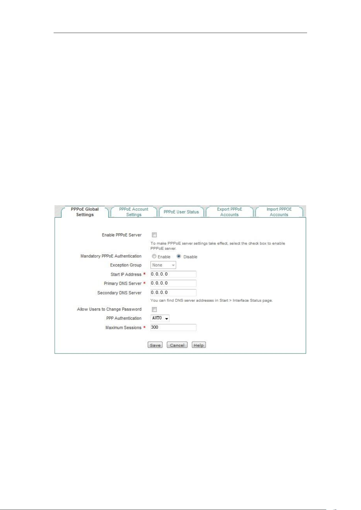
Chapter 9 Wireless configuration
9.3.7 Instance of PPPoE server configuration
1. Demand: Only the users authenticated by the Intranet can access the Internet.
Now, 3 accounts are configured for intranet users, and their user names are test1, test2, and test3
respectively. Initial passwords are: password1, password2, password3, in which test1, test2 are
separately bound with 10.0.0.1, 10.0.0.2 and the charging feature is enabled (the using period of
the account is from October 1, 2012 to December 31, 2013) and a notification is issued 15 days
prior to account expiration; the maximum number of sessions of test3 is set to 5.
2. Configuration steps:
1) Configure the PPPoE server. Log on to the device, enter the User management ->PPPoE
server page, configure the content as shown in the figure below, and enable the forced PPPoE
authentication and allow users to modify the dial-up password (The password change
message can be given to users by configuring the routine business notification feature).
Figure 9_16 Instance - PPPoE Global Settings
2) Configuration of PPPoE account. Enter the PPPoE account Settings. Click on the <Add
new entry>, configure a PPPoE account, bind the account with the IP address, and enable the
charging feature. The configured content with the user name of test1 is as shown in the figure
below:
http://www.level1.com Page 97
Page 98
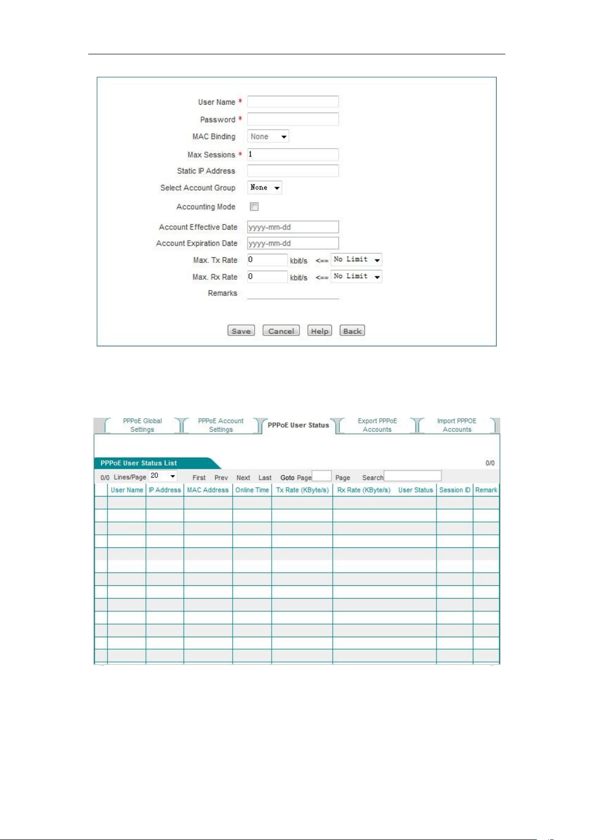
Chapter 9 Wireless configuration
Figure 9_17 PPPoE account Settings
3) Repeat Step 2, and configure the account with the PPPoE user name as test2. Bind it with
10.0.0.2. Configure the account of test3, and set the maximum number of sessions for its
account to 5.
Figure 9_18 Instance - PPPoE User Status List
4) Configure the account expiration notification feature. Enter the Behavior management->
Electronic notification-> Account expiration notification page, to configure the account
expiration notification feature, here, the "Send days of expiration notification in advance" is
set to 15 days.
5) Create a client on the Intranet user's computer.
http://www.level1.com Page 98
Page 99
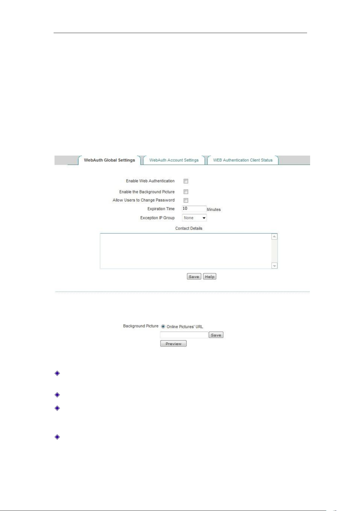
Chapter 9 Wireless configuration
9.4 WEB authentication
9.4.1 WebAuth Global Settings
Enter the User management->WEB certification page to configure the WEB authentication
feature of the device. WEB Authentication is used to authenticate Intranet users as to having
permission to access the Internet, that is, after enabling this feature, the intranet users cannot
access to the Internet unless passing the WEB authentication.
Figure 9_19 WebAuth Global Settings
Enable WEB authentication: Checking it means that the intranet users cannot access the
Internet unless passing the WEB authentication.
Enable background image: Check it to enable this feature.
Allow users to modify authentication password: Checking it means to allow the WEB
authentication users to modify the authentication password on their own.
Exception address group: After the device enables the forced PPPoE authentication, the users
of the address group can communicate with external network without WEB authentication,
and the address group needs to be configured in the User management -> User group
Settings page.
http://www.level1.com Page 99
Page 100
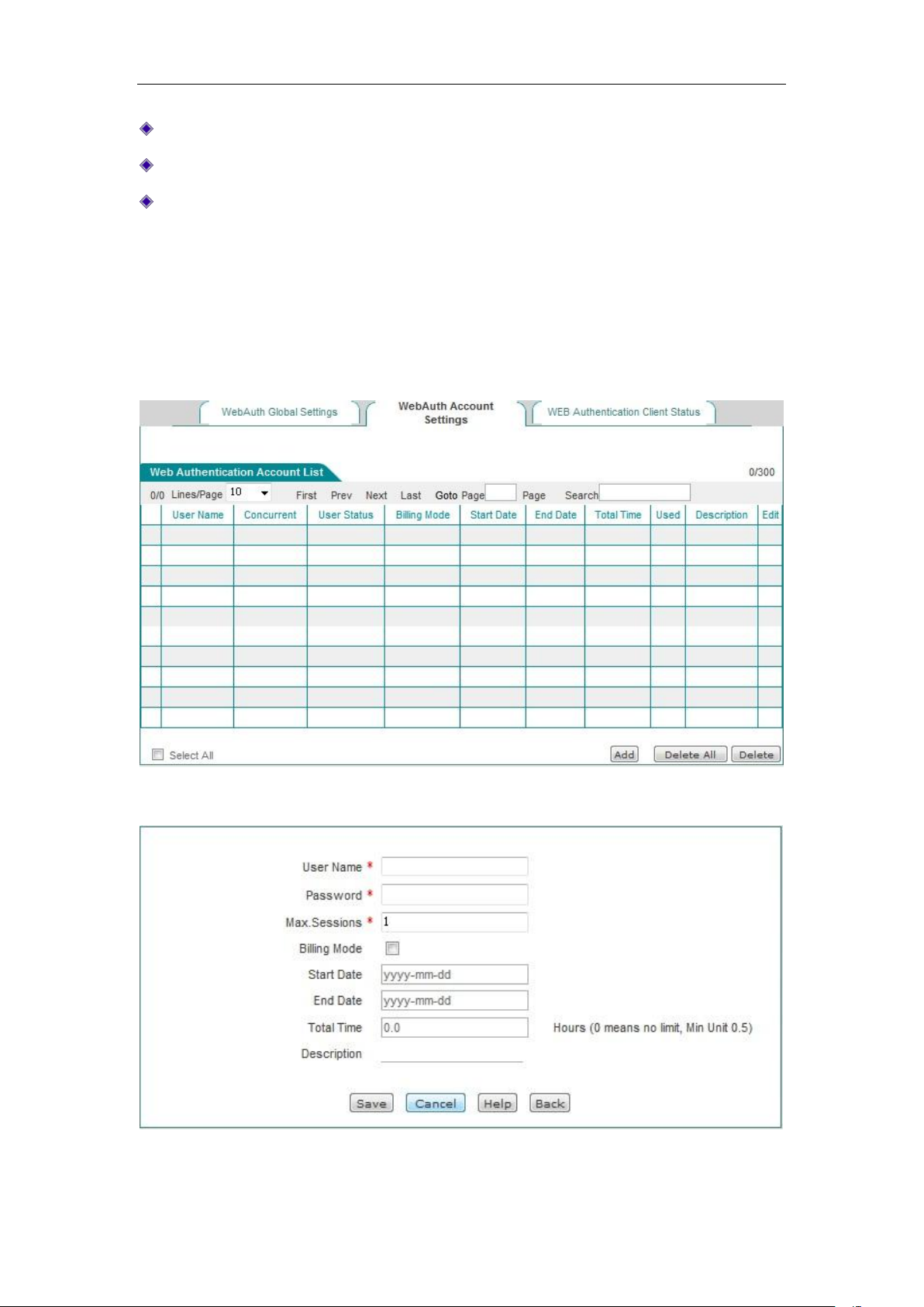
Chapter 9 Wireless configuration
Window title: The title of the custom WEB authentication pop-up window.
Window tip text: Tip texts for custom WEB authentication pop-up window.
Network image link: Enters the network link to the picture, to make this picture as the
background of the WEB authentication pop-up window.
9.4.2 Web Authentication Account List
Figure 9_20 Web Authentication Account List
Figure 9_21 Web Authentication Account List - Add new entry
http://www.level1.com Page 100
 Loading...