

Page 1
LevelOne
WAP-6012
300Mbps N_Max Wireless Gigabit PoE Access Point
User Manual
V1.0
Page 2

TABLE OF CONTENTS
CHAPTER 1 INTRODUCTION ...................................................................................... 1
Features of your Wireless Access Point ............................................................ 1
Package Contents ................................................................................................. 3
Physical Details..................................................................................................... 3
CHAPTER 2 INSTALLATION ....................................................................................... 6
Requirements ........................................................................................................ 6
Procedure .............................................................................................................. 6
CHAPTER 3 ACCESS POINT SETUP .......................................................................... 9
Overview ................................................................................................................ 9
Setup using a Web Browser .............................................................................. 10
System Basic Settings Screen .......................................................................... 13
System Advanced Settings Screen ................................................................... 15
Wireless Screens ................................................................................................ 17
Basic Screen ....................................................................................................... 17
Virtual AP Settings .............................................................................................. 19
Virtual AP Screen ................................................................................................ 20
Radius Server Settings ...................................................................................... 32
Access Control .................................................................................................... 33
Advanced Settings ............................................................................................. 36
Wi-Fi Protected Setup ........................................................................................ 38
CHAPTER 4 PC AND SERVER CONFIGURATION ................................................... 39
Overview .............................................................................................................. 39
Using WEP ........................................................................................................... 39
Using WPA-PSK/WPA2-PSK .............................................................................. 40
Using WPA-Enterprise........................................................................................ 41
802.1x Server Setup (Windows 2000 Server) ................................................... 42
802.1x Client Setup on Windows XP ................................................................. 52
Using 802.1x Mode (without WPA) .................................................................... 58
CHAPTER 5 OPERATION AND STATUS .................................................................. 59
Operation ............................................................................................................. 59
Status Screen ...................................................................................................... 59
CHAPTER 6 ACCESS POINT MANAGEMENT .......................................................... 66
Overview .............................................................................................................. 66
Admin Login Screen ........................................................................................... 66
Auto Config/Update ............................................................................................ 68
Config File ........................................................................................................... 69
SNMP ................................................................................................................... 71
Log Settings ........................................................................................................ 73
Firmware Upgrade .............................................................................................. 75
APPENDIX A SPECIFICATIONS ................................................................................ 76
Wireless Access Point ........................................................................................ 76
APPENDIX B TROUBLESHOOTING ......................................................................... 80
Overview .............................................................................................................. 80
General Problems ............................................................................................... 80
APPENDIX C WINDOWS TCP/IP ............................................................................... 82
Overview .............................................................................................................. 82
Checking TCP/IP Settings - Windows 9x/ME: .................................................. 82
Checking TCP/IP Settings - Windows NT4.0 .................................................... 84
Checking TCP/IP Settings - Windows 2000 ...................................................... 86
Page 3

Checking TCP/IP Settings - Windows XP ......................................................... 88
Checking TCP/IP Settings - Windows Vista ..................................................... 90
APPENDIX D ABOUT WIRELESS LANS ................................................................... 92
Overview .............................................................................................................. 92
Wireless LAN Terminology ................................................................................ 92
APPENDIX E COMMAND LINE INTERFACE ............................................................ 95
Overview .............................................................................................................. 95
Command Reference .......................................................................................... 95
All trademarks and trade names are the properties of their respective owners.
Page 4

Page 5
1
Chapter 1
Introduction
This Chapter provides an overview of the Wireless Access Point's features and capabilities.
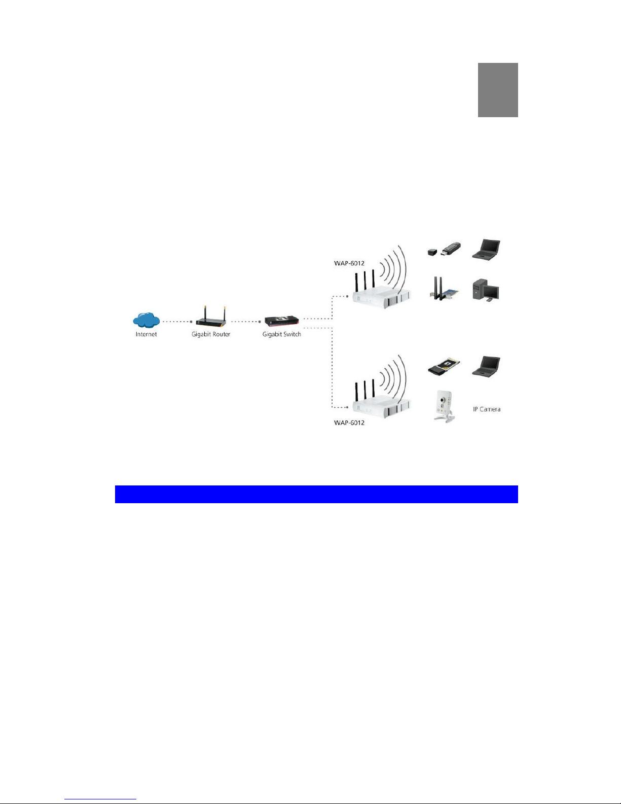
Congratulations on the purchase of your new Wireless Access Point. The Wireless
Access Point links your Wireless Stations to your wired LAN. The Wireless stations
and devices on the wired LAN are then on the same network, and can communicate
with each other without regard for whether they are connected to the network via a
Wireless or wired connection.
Figure 1: Wireless Access Point
Features of your Wireless Access Point
The Wireless Access Point incorporates many advanced features, carefully designed
to provide sophisticated functions while being easy to use.
Standards Compliant. The Wireless Access Point complies with the
IEEE802.11g and IEEE802.11n specifications for Wireless LANs.
Supports 11n Wireless Stations. The 802.11n standard provides for back-
ward compatibility with the 802.11b standard, so 802.11n, 802.11b and 802.11g
Wireless stations can be used simultaneously.
Bridge Mode Support. The Wireless Access Point can operate in Bridge
Mode, connecting to another Access Point. Both PTP (Point to Point) and PTMP
(Point to Multi-Point) Bridge modes are supported.
And you can even use both Bridge Mode and Access Point Mode simultaneously!
WPS Support. WPS (Wi-Fi Protected Setup) can simplify the process of con-
necting any device to the wireless network by using the push button configuration
(PBC) on the Wireless Access Point, or entering a 8-digit PIN code if there's no
button.
1
Page 6

Wireless Access Point User Guide
2
DHCP Client Support. Dynamic Host Configuration Protocol provides a dy-
namic IP address to PCs and other devices upon request. The Wireless Access
Point can act as a DHCP Client, and obtain an IP address and related information
from your existing DHPC Server.
Upgradeable Firmware. Firmware is stored in a flash memory and can be
upgraded easily, using only your Web Browser.
PoE Support. You can use PoE (Power over Ethernet) to provide power to the
Wireless Access Point, so only a single cable connection is required.
Security Features
Virtual APs. For maximum flexibility, wireless security settings are stored in
Virtual AP. Up to 4 Virtual APs can be defined and used as any time.
Multiple BSSIDs. Because each Virtual AP has it own SSID and beacon, and
up to 4 Virtual APs can be active simultaneously, multiple SSIDs are supported.
Different clients can connect to the Wireless Access Point using different SSIDs,
with different security settings.
Virtual APs Isolation. If desired, PCs and devices connecting to different
Virtual APs can be isolated from each other.
VLAN Support. The 802.1Q VLAN standard is supported, allowing traffic from
different sources to be segmented. Combined with the multiple SSID feature, this
provides a powerful tool to control access to your LAN.
WEP support. Support for WEP (Wired Equivalent Privacy) is included. Both 64
Bit 128 Bit, and 152 Bit keys are supported.
WPA support. Support for WPA is included. WPA is more secure than WEP,
and should be used if possible. Both TKIP and AES encryption methods are supported.
802.1x Support. Support for 802.1x mode is included, providing for the industri-
al-strength wireless security of 802.1x authentication and authorization.
Radius Client Support. The Wireless Access Point can login to your existing
Radius Server (as a Radius client).
Radius MAC Authentication. You can centralize the checking of Wireless
Station MAC addresses by using a Radius Server.
Rogue AP Detection. The Wireless Access Point can detect unauthorized
(Rouge) Access Points on your LAN.
Access Control. The Access Control feature can check the MAC address of
Wireless clients to ensure that only trusted Wireless Stations can use the Wireless
Access Point to gain access to your LAN.
Password - protected Configuration. Optional password protection is
provided to prevent unauthorized users from modifying the configuration data and
settings.
Advanced Features
Command Line Interface. If desired, the command line interface (CLI) can be
used for configuration. This provides the possibility of creating scripts to perform
common configuration changes.
Auto Configuration. The Wireless Access Point can perform self-configuration
by copying the configuration data from another Access Point. This feature is
enabled by default.
Page 7
Introduction
3
Auto Update. The Wireless Access Point can automatically update its firmware,
by downloading and installing new firmware from your FTP server.
Radius Accounting Support. If you have a Radius Server, you can use it to
provide accounting data on Wireless clients.
Syslog Support. If you have a Syslog Server, the Wireless Access Point can
send its log data to your Syslog Server.
SNMP Support. SNMP (Simple Network Management Protocol) is supported,
allowing you to use a SNMP program to manage the Wireless Access Point.
Package Contents
The following items should be included:
Wireless Access Point
Power Adapter
Quick Start Guide
CD-ROM containing the manual.
If any of the above items are damaged or missing, please contact your dealer immediately.
Physical Details
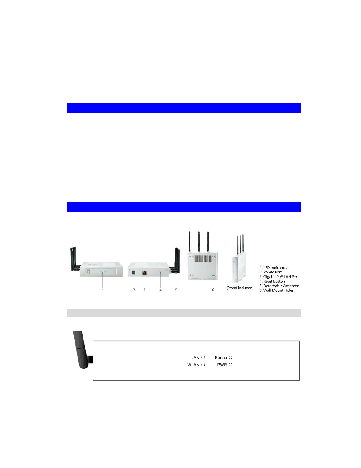
Front Panel LEDs
Figure 2: Front Panel
Power
On - Normal operation.
Off - No power
Page 8

Wireless Access Point User Guide
4
WLAN
On - Idle
Off - Wireless connection is not available.
Flashing - Data is being transmitted or received via the Wireless
access point. Data includes "network traffic" as well as user data.
Status
On - Error condition.
Off - Normal operation.
Blinking - During start up, and when the Firmware is being up-
graded.
Ethernet
On - The LAN (Ethernet) port is active.
Off - No active connection on the LAN (Ethernet) port.
Flashing - Data is being transmitted or received via the correspond-
ing LAN (Ethernet) port.
Page 9

Introduction
5
Rear Panel
Figure 3: Rear Panel
Reset Button
This button has two (2) functions:
Reboot. When pressed and released, the Wireless Access
Point will reboot (restart).
Reset to Factory Defaults. This button can also be used to
clear ALL data and restore ALL settings to the factory default
values.
To Clear All Data and restore the factory default values:
1. Hold the Reset Button until the Status (Red) LED blinks
TWICE, usually more than 5 seconds.
2. Release the Reset Button.
The factory default configuration has now been restored, and
the Access Point is ready for use.
LAN
Use a standard LAN cable (RJ45 connectors) to connect this
port to a 10/100/1000BaseT hub/switch on your LAN.
Power port
Connect the supplied power adapter (12V@1A) here.
Page 10

6
Chapter 2
Installation
This Chapter covers the physical installation of the Wireless Access
Point.
Requirements
Requirements:
TCP/IP network
Ethernet cable with RJ-45 connectors
Installed Wireless network adapter for each PC that will be wirelessly connected to
the network
Procedure
1. Select a suitable location for the installation of your Wireless Access Point. To
maximize reliability and performance, follow these guidelines:
Use an elevated location, such as wall mounted or on the top of a cubicle.
Place the Wireless Access Point near the center of your wireless coverage
area.
If possible, ensure there are no thick walls or metal shielding between the
Wireless Access Point and Wireless stations. Under ideal conditions, the
Wireless Access Point has a range of around 150 meters (450 feet). The
range is reduced, and transmission speed is lower, if there are any obstructions between Wireless devices.
2
Page 11
Installation
7
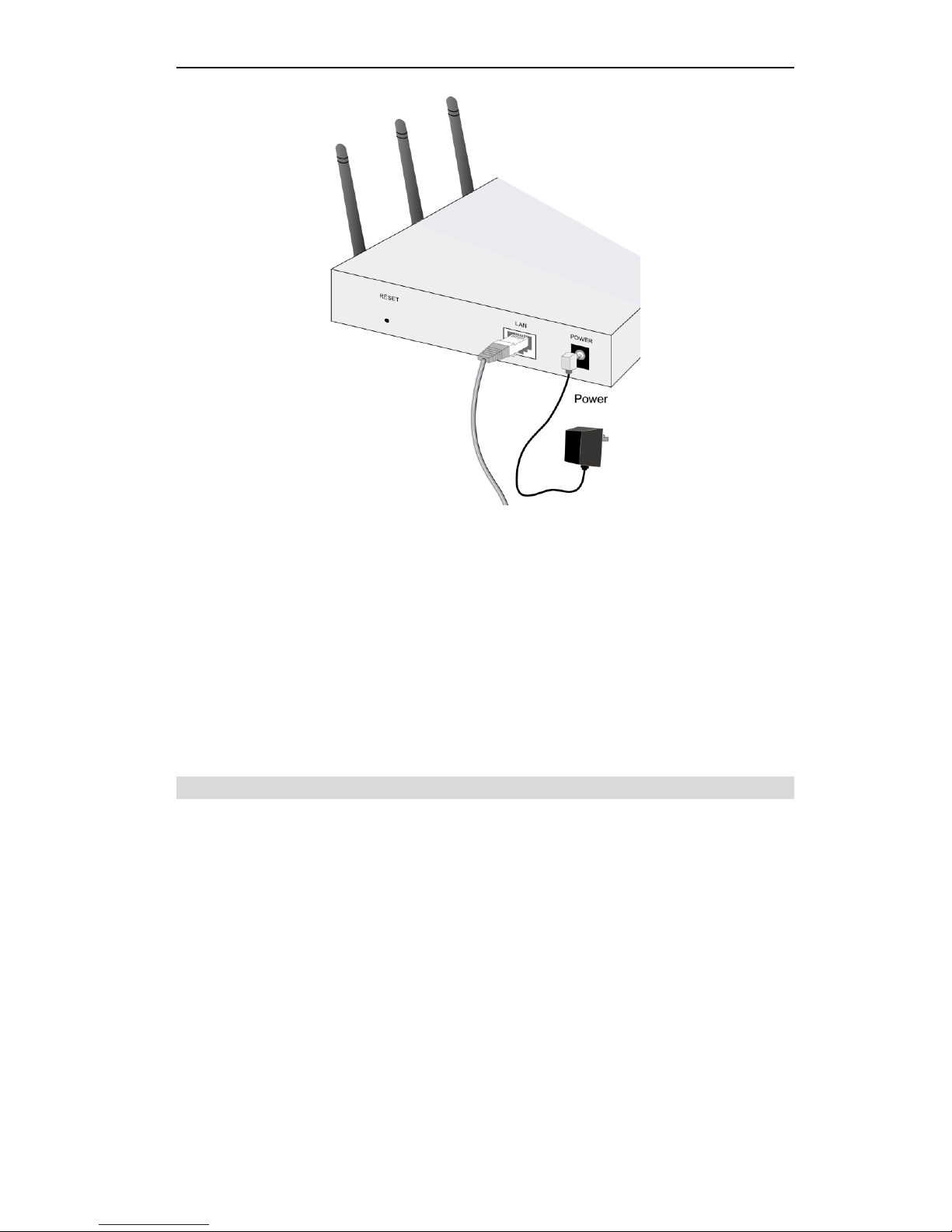
Figure 4: Installation Diagram
2. Use a standard LAN cable to connect the "LAN" port on the Wireless Access Point
to a 10/100/1000BaseT hub/switch on your LAN.
3. Connect the supplied power adapter to the Wireless Access Point and a convenient power outlet, and power up.
4. Check the LEDs:
The Status LED should flash, then turn OFF.
The Power, Ethernet and WLAN LEDs should be ON.
For more information, refer to Front Panel LEDs in Chapter 1.
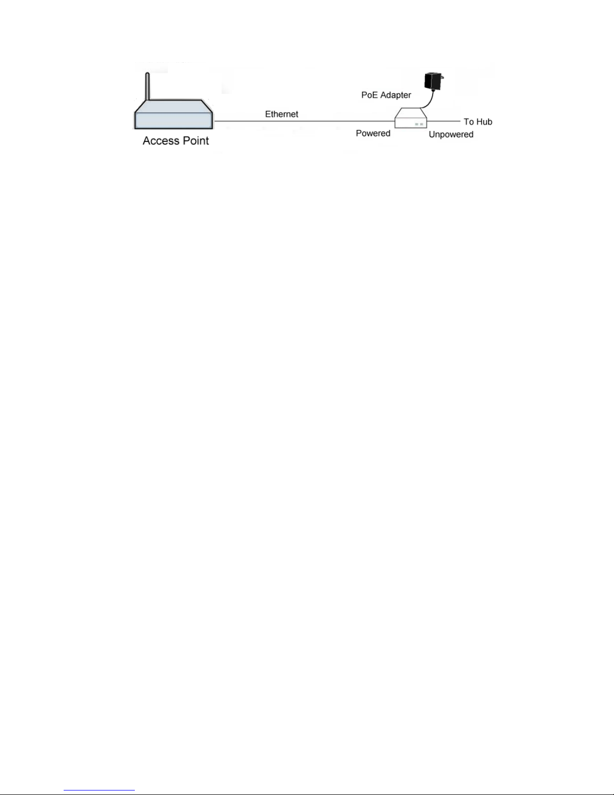
Using PoE (Power over Ethernet)
The Wireless Access Point supports PoE (Power over Ethernet). To use PoE:
5. Do not connect the supplied power adapter to the Wireless Access Point.
6. Connect one end of a standard (category 5) LAN cable to the Ethernet port on the
Wireless Access Point.
7. Connect the other end of the LAN cable to the powered Ethernet port on a suitable
PoE Adapter. (24V DC, 500mA)
8. Connect the unpowered Ethernet port on the PoE adapter to your Hub or switch.
9. Connect the power supply to the PoE adapter and power up.
10. Check the LEDs on the Wireless Access Point to see it is drawing power via the
Ethernet connection.
Page 12
Wireless Access Point User Guide
8
Figure 5: Using PoE (Power over Ethernet)
Page 13

9
Chapter 3
Access Point Setup
This Chapter provides details of the Setup process for Basic Operation
of your Wireless Access Point.
Overview
This chapter describes the setup procedure to make the Wireless Access Point a valid
device on your LAN, and to function as an Access Point for your Wireless Stations.
Wireless Stations may also require configuration. For details, see Chapter 4 - PC and
Server Configuration.
The Wireless Access Point can be configured using your Web Browser
3
Page 14
Wireless Access Point User Guide
10
Setup using a Web Browser
Your Browser must support JavaScript. The configuration program has been tested
on the following browsers:
Internet Explorer V4 or later
Netscape V4.08 or later
Setup Procedure
Before commencing, install the Wireless Access Point in your LAN, as described
previously.
1. Check the Wireless Access Point to determine its Default Name. This is shown on
a label on the base or rear, and is in the following format:
WAP-6012
2. Use a PC which is already connected to your LAN, either by a wired connection or
another Access Point.
Until the Wireless Access Point is configured, establishing a Wireless connec-
tion to it may be not possible.
If your LAN contains a Router or Routers, ensure the PC used for configura-
tion is on the same LAN segment as the Wireless Access Point.
3. Start your Web browser.
4. In the Address box, enter "HTTP://" and the IP Address of the 11N Wireless
Access Point, as in this example, which uses the Wireless Access Point's default
IP Address:
HTTP://192.168.1.1
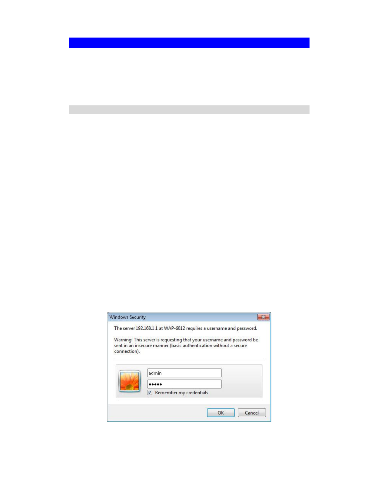
5. You should then see a login prompt, which will ask for a User Name and Password.
Enter admin for the User Name, and admin for the Password.
These are the default values. The password can and should be changed. Always
enter the current user name and password, as set on the Admin Login screen.
User Name: admin
Password: admin
Figure 6: Password Dialog
Page 15

Access Point Setup
11
6. You will then see the Status screen, which displays the current settings and status.
No data input is possible on this screen. See Chapter 5 for details of the Status
screen.
Page 16

Wireless Access Point User Guide
12
7. From the menu, check the following screens, and configure as necessary for your
environment. Details of these screens and settings are described in the following
sections of this chapter.
System - Basic and Advanced settings
Wireless - Basic, Advanced, Access Control, Radius Server, Virtual APs &
WIFI Protected Setup.
8. You may also wish to set the admin password and administration connection
options. These are on the Admin Login screen accessed from the Management
menu. See Chapter 6 for details of the screens and features available on the
Management menu.
9. Use the Apply and Reboot buttons on the menu to apply your changes and restart
the Wireless Access Point.
Setup is now complete.
Wireless stations must now be set to match the Wireless Access Point. See Chapter 4
for details.
If you can't connect:
It is likely that your PC’s IP address is incompatible with the Wireless
Access Point’s IP address. This can happen if your LAN does not have a
DHCP Server.
The default IP address of the Wireless Access Point is 192.168.1.1, with a
Network Mask of 255.255.255.0.
If your PC’s IP address is not compatible with this, you must change your
PC’s IP address to an unused value in the range 192.168.1.50 ~
192.168.1.200, with a Network Mask of 255.255.255.0. See Appendix C Windows TCP/IP for details for this procedure.
Page 17
Access Point Setup
13
System Basic Settings Screen
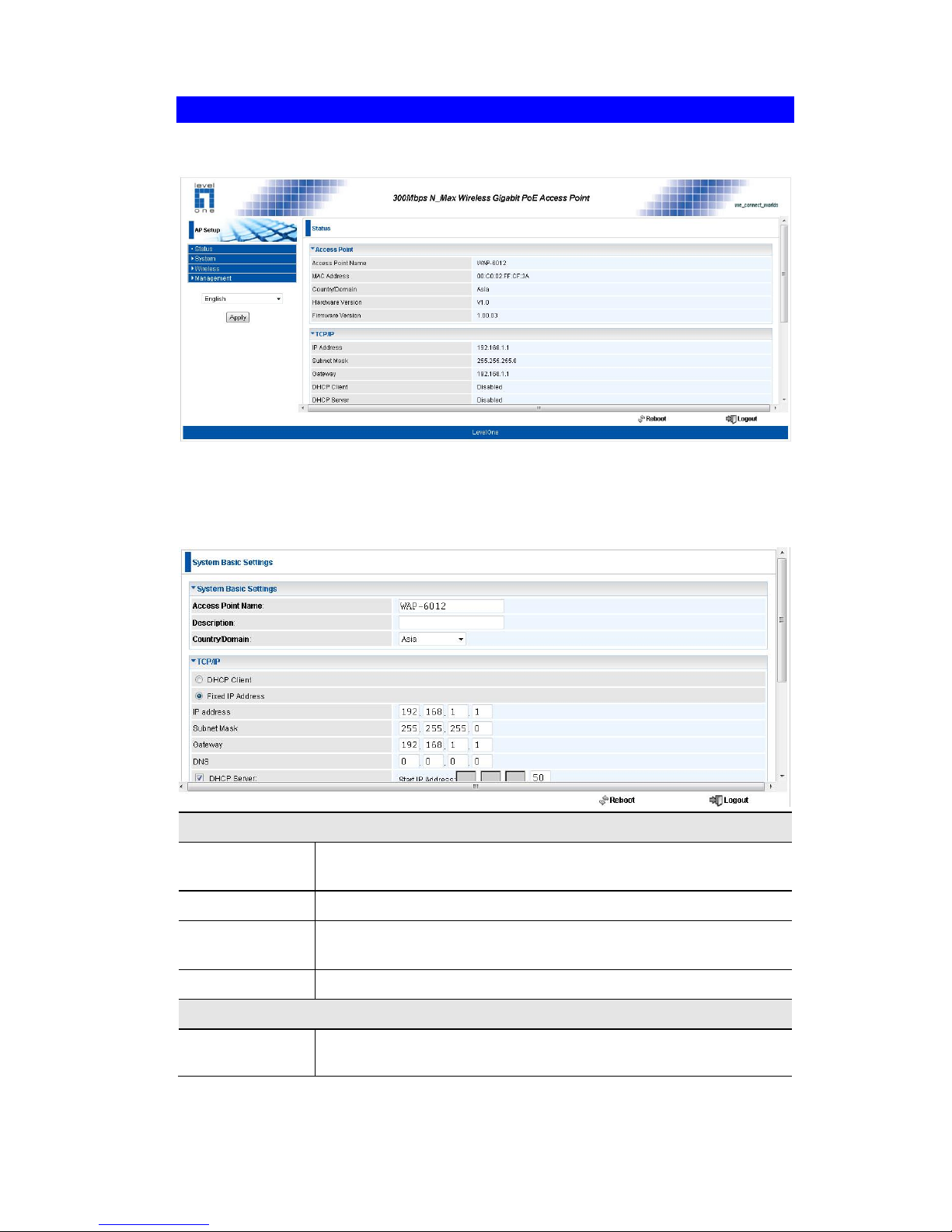
Click Basic Settings on the System menu to view a screen like the following.
Figure 7: System Basic Settings Screen
Data - System Basic Settings Screen
Identification
Access Point
Name
Enter a suitable name for this Access Point.
Description
If desired, you can enter a description for the Access Point.
Country Domain
The country or domain which is matching your current location.
MAC Address
The MAC address is displayed.
IP Settings
DHCP Client
Select this option if you have a DHCP Server on your LAN, and
you wish the Access Point to obtain an IP address automatically.
Page 18

Wireless Access Point User Guide
14
Fixed IP Address
If selected, the following data must be entered.
IP Address - The IP Address of this device. Enter an unused
IP address from the address range on your LAN.
Subnet Mask - The Network Mask associated with the IP
Address above. Enter the value used by other devices on
your LAN.
Gateway - The IP Address of your Gateway or Router. Enter
the value used by other devices on your LAN.
DNS - Enter the DNS (Domain Name Server) used by PCs
on your LAN.
DHCP Server
If Enabled, the Access Point will allocate IP Addresses to
PCs (DHCP clients) on your LAN when they start up. The default (and recommended) value is Enabled.
The Start IP Address and Finish IP Address fields set the
values used by the DHCP server when allocating IP Addresses to DHCP clients. This range also determines the
number of DHCP clients supported.
Wins Server
Name/IP Address
Enter the server name or IP address of the Wins Server.
TimeZone
TimeZone
Choose the Time Zone for your location from the drop-down list.
If your location is currently using Daylight Saving, enable the
Adjust for
Daylight Saving Time checkbox.
You must UNCHECK this checkbox when Daylight Saving
Time finishes.
NTP Server
Name/IP Address
Enter the server name or IP address of the NTP.
Page 19
Access Point Setup
15
System Advanced Settings Screen
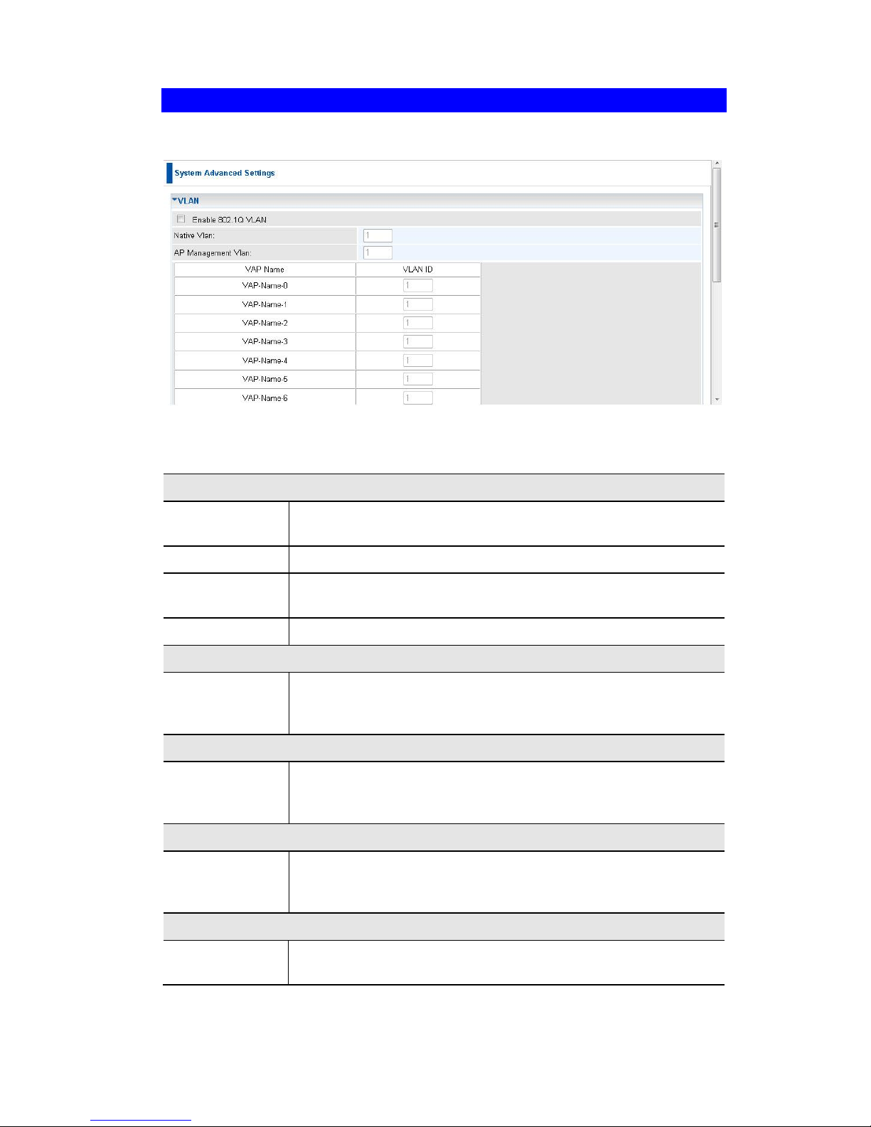
Click Advanced Settings on the System menu to view a screen like the following.
Figure 8: System Advanced Settings Screen
Data - System Advanced Settings Screen
VLAN
Enable 802.1Q
VLAN
This option is only useful if the hubs/switches on your LAN
support the VLAN standard.
Native VLAN
Enter the desired value for the Native VLAN. Default value is 1.
AP Management VLAN
Define the VLAN ID used for management.
VLAN List
Define the unique ID value (1 - 4094) for each VAP.
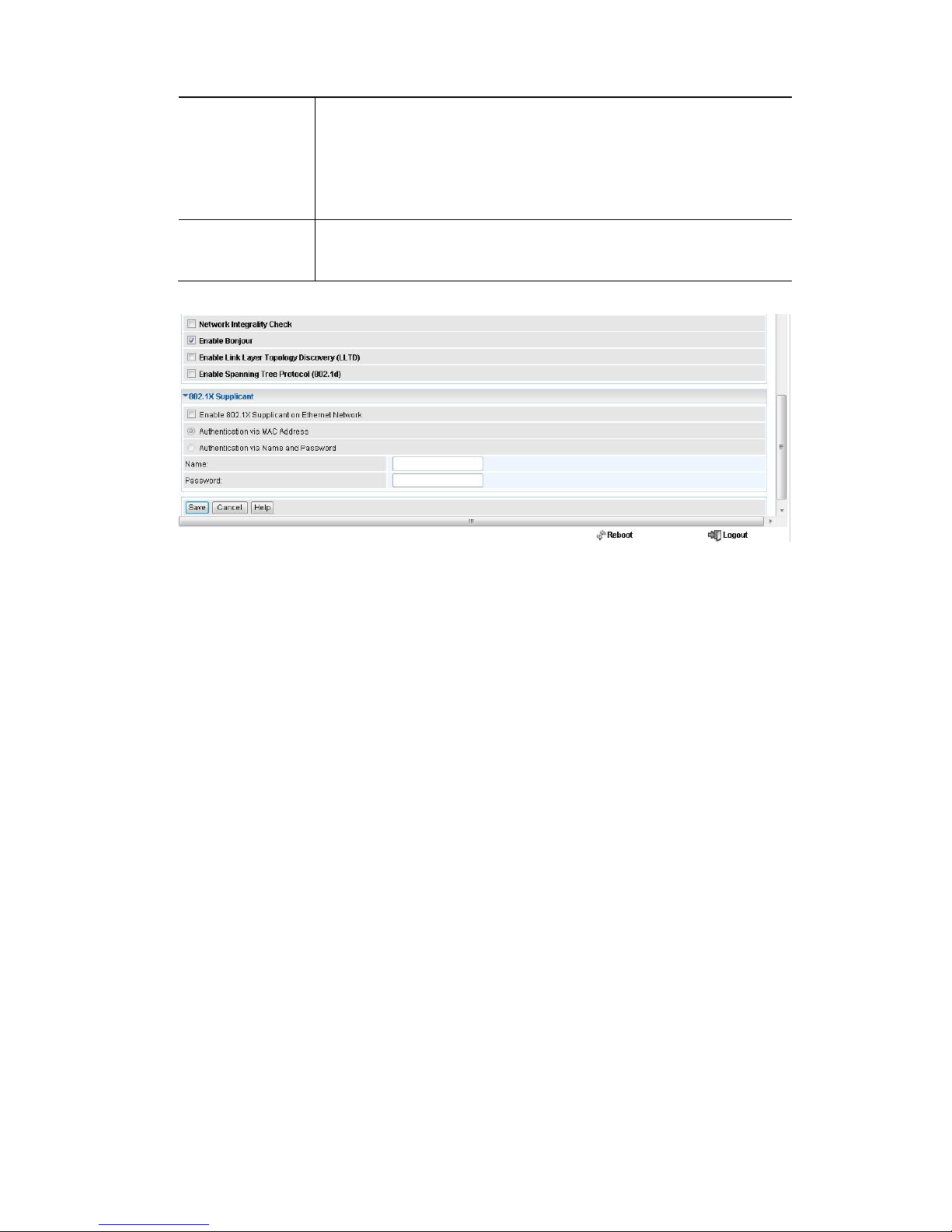
Network Integrality Check
Enable Network Integrality
Check
If enabled, the AP will disable the wireless connection if the wired
connect of AP is invalid.
LLTD
Enable Link
Layer Topology
Discovery
Enable this if you want to use Link Layer Topology Discovery
protocol (LLTD) feature.
STP
Enable Spanning tree
Protocol
Enable this if you want to use this feature.
802.1x Supplicant
Enable 802.1x
Supplicant
Enable this if your network requires this AP to use 802.X authentication in order to operate.
Page 20
Wireless Access Point User Guide
16
Authentication
Authentication via MAC Address
Select this if you want to Use MAC Address for Authentication.
Authentication via Name and Password
Select this if you want to Use name and password for Authentication.
Bonjour
Zero-configuration networking, enables automatic discovery
of computers, devices, and services on IP networks using
industry standard IP protocols
Page 21
Access Point Setup
17
Wireless Screens
There are 6 configuration screens available:
Basic
Virtual Aps
Radius Server Settings
Access Control
Advanced Settings
Wi-Fi Protected Setup
Basic Setting
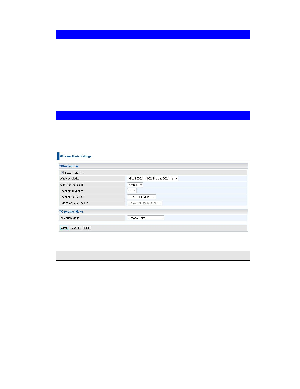
The settings on this screen must match the settings used by Wireless Stations.
Click Basic Settings on the Wireless menu to view a screen like the following.
Figure 9:Wireless Basic Setting
Data - Wireless Basic Settings Setting
Operation
Turn Radio On
Enable this to use the wireless feature.
Wireless Mode
Select the desired option:
Disable - select this if for some reason you do not this AP to
transmit or receive at all.
802.11b - if selected, only 802.11b connections are allowed.
802.11g wireless stations will only be able to connect if they
are fully backward-compatible with the 802.11b standard.
802.11g - only 802.11g connections are allowed. If you only
have 802.11g, selecting this option may provide a performance improvement over using the default setting.
802.11n - only 802.11n connections are allowed. If you only
have 802.11n, selecting this option may provide a performance improvement over using the default setting.
802.11b and 802.11g - this will allow connections by both
Page 22

Wireless Access Point User Guide
18
802.11b and 802.11g wireless stations.
802.11n and 802.11g - this will allow connections by both
802.11n and 802.11g wireless stations.
Mixed 802.11n/802.11g/802.11b - this is the default, and will
allow connections by 802.11n, 802.11b and 802.11g wireless
stations.
Auto Channel
Scan
If "Enable" is selected, the Access Point will select the best
available Channel.
Channel
/Frequency
If you experience interference (shown by lost connections and/or
slow data transfers) you may need to experiment with manually
setting different channels to see which is the best.
Channel
Bandwidth
Select the desired bandwidth from the list.
Extension
Sub-Channel
Select Above or Below Primary Channel from the list.
Operation
Mode
Select the desired mode:
Access Point - operate as a normal Access Point
Bridge (Point-to-Point) - Bridge to a single AP. You must
provide the MAC address of the other AP in the PTP Bridge
AP MAC Address field.
Bridge (Multi-Point) - Select this only if this AP is the "Mas-
ter" for a group of Bridge-mode APs. The other Bridge-mode
APs must be set to Point-to-Point Bridge mode, using this
AP's MAC address. They then send all traffic to this "Master".
Wireless Client/Repeater - Act as a client or repeater for
another Access Point. If selected, you must provide Remote
SSID and the address (MAC address) of the other AP in the
Remote AP MAC Address field. In this mode, all traffic is
sent to the specified AP.
Wireless Detection - This mode will turn the access point
into a wireless Monitor. A "Rouge AP" is an Access Point
which should not be in use, and so can be considered to be
providing unauthorized access to your LAN.
No Security - If checked, then any AP operating with se-
curity disabled is considered to be a Rogue AP.
Not in Legal AP List - If checked, then any AP not listed
in the "Legal AP List" is considered to be a Rogue AP. If
checked, you must maintain the Legal AP List.
Define Legal AP - Click this to open a sub-screen where
you can modify the "Legal AP List". This list must contain
all known APs, so must be kept up to date.
Remote MAC
Address
You must enter the MAC address(es) of other AP(s) in the fields.
Select Remote
AP
If the other AP is on-line, you can click the "Select Remote AP"
button and select from a list of available APs.
Page 23
Access Point Setup
19
Virtual AP Settings
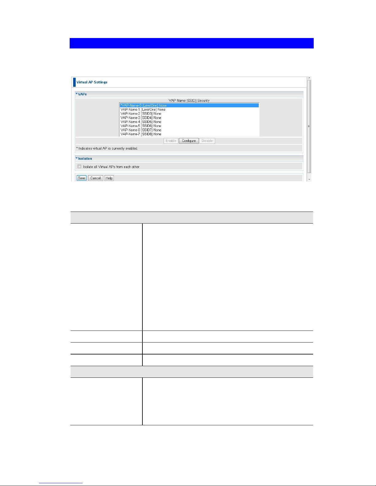
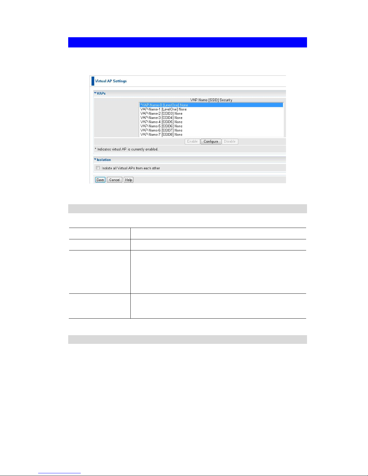
Clicking the Virtual APs link on the Wireless menu will result in a screen like the following.
Figure 10: Virtual AP Settings
Data - Virtual AP Settings Screen
VAPs
VAP List
All available VAPs are listed. For each VAP, the following
data is displayed:
*
If displayed before the name of the VAP, this indicates the VAP is currently enabled. If not
displayed, the VAP is currently disabled.
VAP Name
The current VAP name is displayed.
[SSID]
The current SSID associated with this VAP.
Security System
The current security system (e.g. WPA-PSK ) is
displayed.
Enable Button
Enable the selected VAP.
Configure Button
Change the settings for the selected VAP.
Disable Button
Disable the selected VAP.
Isolation
Isolate all Virtual APs
from each other
If this option is enabled, wireless clients using different
VAPs (different SSIDs) are isolated from each other, so
they will NOT be able to communicate with each other.
They will still be able to communicate with other clients
using the same profile, unless the "Wireless Separation"
setting on the "Advanced" screen has been enabled.
Page 24
Wireless Access Point User Guide
20
Virtual AP Setting
This screen is displayed when you select a VAP on the Virtual AP Settings screen, and
click the Configure button.
Figure 11: Virtual AP Setting
VAP Data
Enter the desired settings for each of the following:
VAP Name
Enter a suitable name for this VAP.
SSID
Enter the desired SSID. Each VAP must have a unique SSID.
Broadcast SSID
If Disabled, no SSID is broadcast.
If enabled, the SSID will then be broadcast to all Wireless
Stations. Stations which have no SSID (or a "null" value) can
then adopt the correct SSID for connections to this Access
Point.
Isolation within
VAP
If enabled, then each Wireless station using the Access Point
is invisible to other Wireless stations. In most business stations, this setting should be Disabled.
Security Settings
Select the desired option, and then enter the settings for the selected method.
The available options are:
None - No security is used. Anyone using the correct SSID can connect to your
network.
WEP - The 802.11b standard. Data is encrypted before transmission, but the
encryption system is not very strong.
WPA-PSK - Like WEP, data is encrypted before transmission. WPA is more
secure than WEP, and should be used if possible. The PSK (Pre-shared Key)
must be entered on each Wireless station. The 256Bit encryption key is derived
from the PSK, and changes frequently.
Page 25

Access Point Setup
21
WPA2-PSK - This is a further development of WPA-PSK, and offers even greater
security, using the AES (Advanced Encryption Standard) method of encryption.
WPA-PSK and WPA2-PSK - This method, sometimes called "Mixed Mode",
allows clients to use EITHER WPA-PSK (with TKIP) OR WPA2-PSK (with AES).
WPA with Radius - This version of WPA requires a Radius Server on your LAN to
provide the client authentication according to the 802.1x standard. Data transmissions are encrypted using the WPA standard.
If this option is selected:
This Access Point must have a "client login" on the Radius Server.
Each user must have a "user login" on the Radius Server.
Each user's wireless client must support 802.1x and provide the login data
when required.
All data transmission is encrypted using the WPA standard. Keys are automat-
ically generated, so no key input is required.
WPA2 with Radius - This version of WPA2 requires a Radius Server on your LAN
to provide the client authentication according to the 802.1x standard. Data transmissions are encrypted using the WPA2 standard.
If this option is selected:
This Access Point must have a "client login" on the Radius Server.
Each user must authenticate on the Radius Server. This is usually done using
digital certificates.
Each user's wireless client must support 802.1x and provide the Radius au-
thentication data when required.
All data transmission is encrypted using the WPA2 standard. Keys are auto-
matically generated, so no key input is required.
WPA and WPA2 with Radius - EITHER WPA or WPA2 require a Radius Server
on your LAN to provide the client authentication according to the 802.1x standard.
Data transmissions are encrypted using EITHER WPA or WPA2 standard.
If this option is selected:
This Access Point must have a "client login" on the Radius Server.
Each user must authenticate on the Radius Server. This is usually done using
digital certificates.
Each user's wireless client must support 802.1x and provide the Radius au-
thentication data when required.
All data transmission is encrypted using EITHER WPA or WPA2 standard.
Keys are automatically generated, so no key input is required.
802.1x - This uses the 802.1x standard for client authentication, and WEP for data
encryption.
If this option is selected:
This Access Point must have a "client login" on the Radius Server.
Each user must have a "user login" on the Radius Server.
Each user's wireless client must support 802.1x and provide the login data
when required.
All data transmission is encrypted using the WEP standard. You only have to
select the WEP key size; the WEP key is automatically generated.
Page 26
Wireless Access Point User Guide
22
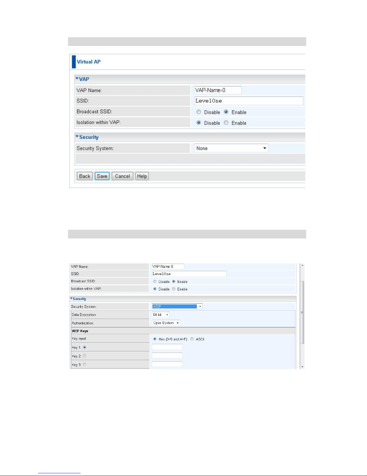
Security Settings - None
Figure 12: Wireless Security - None
No security is used. Anyone using the correct SSID can connect to your network.
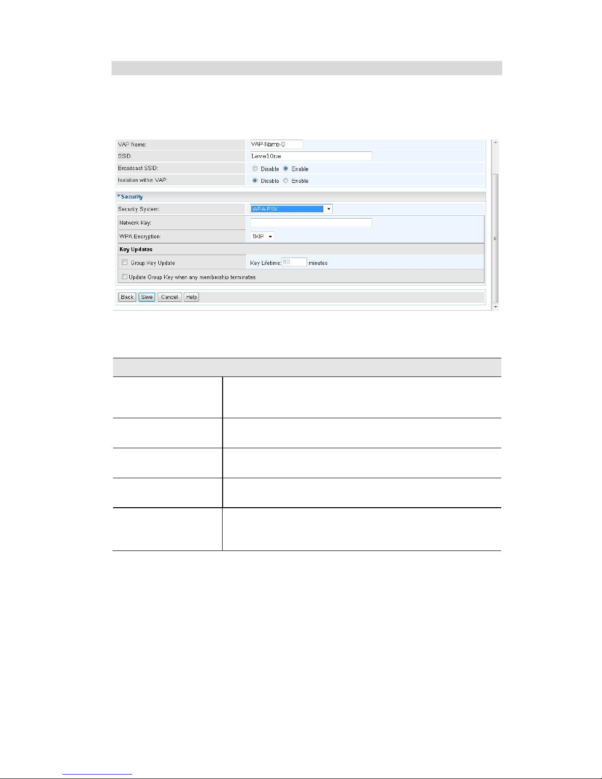
Security Settings - WEP
This is the 802.11b standard. Data is encrypted before transmission, but the encryption
system is not very strong.
Figure 13: WEP Wireless Security Screen
Page 27

Access Point Setup
23
Data - WEP Screen
WEP
Data
Encryption
Select the desired option, and ensure your Wireless stations
have the same setting:
64 Bit Encryption - Keys are 10 Hex (5 ASCII) characters.
128 Bit Encryption - Keys are 26 Hex (13 ASCII) charac-
ters.
152 Bit Encryption - Keys are 32 Hex (16 ASCII) charac-
ters.
Authentication
Normally, you can leave this at “Automatic”, so that Wireless
Stations can use either method ("Open System" or "Shared
Key".).
If you wish to use a particular method, select the appropriate
value - "Open System" or "Shared Key". All Wireless stations
must then be set to use the same method.
Key Input
Select "Hex" or "ASCII" depending on your input method. (All
keys are converted to Hex, ASCII input is only for convenience.)
Key Value
Enter the key values you wish to use. The default key, selected
by the radio button, is required. The other keys are optional.
Other stations must have matching key values.
Passphrase
Use this to generate a key or keys, instead of entering them
directly. Enter a word or group of printable characters in the
Passphrase box and click the "Generate Key" button to automatically configure the WEP Key(s).
Page 28
Wireless Access Point User Guide
24
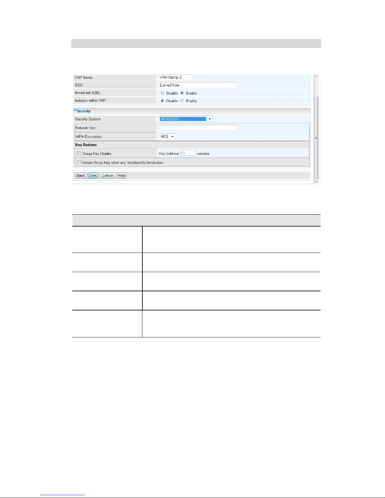
Security Settings - WPA-PSK
Like WEP, data is encrypted before transmission. WPA is more secure than WEP, and
should be used if possible. The PSK (Pre-shared Key) must be entered on each Wireless station. The 256Bit encryption key is derived from the PSK, and changes
frequently.
Figure 14: WPA-PSK Wireless Security Screen
Data - WPA-PSK Screen
WPA-PSK
Network Key
Enter the key value. Data is encrypted using a 256Bit key
derived from this key. Other Wireless Stations must use the
same key.
WPA Encryption
The encryption method is TKIP. Wireless Stations must
also use TKIP.
Group Key Update
This refers to the key used for broadcast transmissions.
Enable this if you want the keys to be updated regularly.
Key Lifetime
This field determines how often the Group key is dynamically updated. Enter the desired value.
Update Group key
when any membership terminates
If enabled, the Group key will be updated whenever any
member leaves the group or disassociates from the Access
Point.
Page 29
Access Point Setup
25
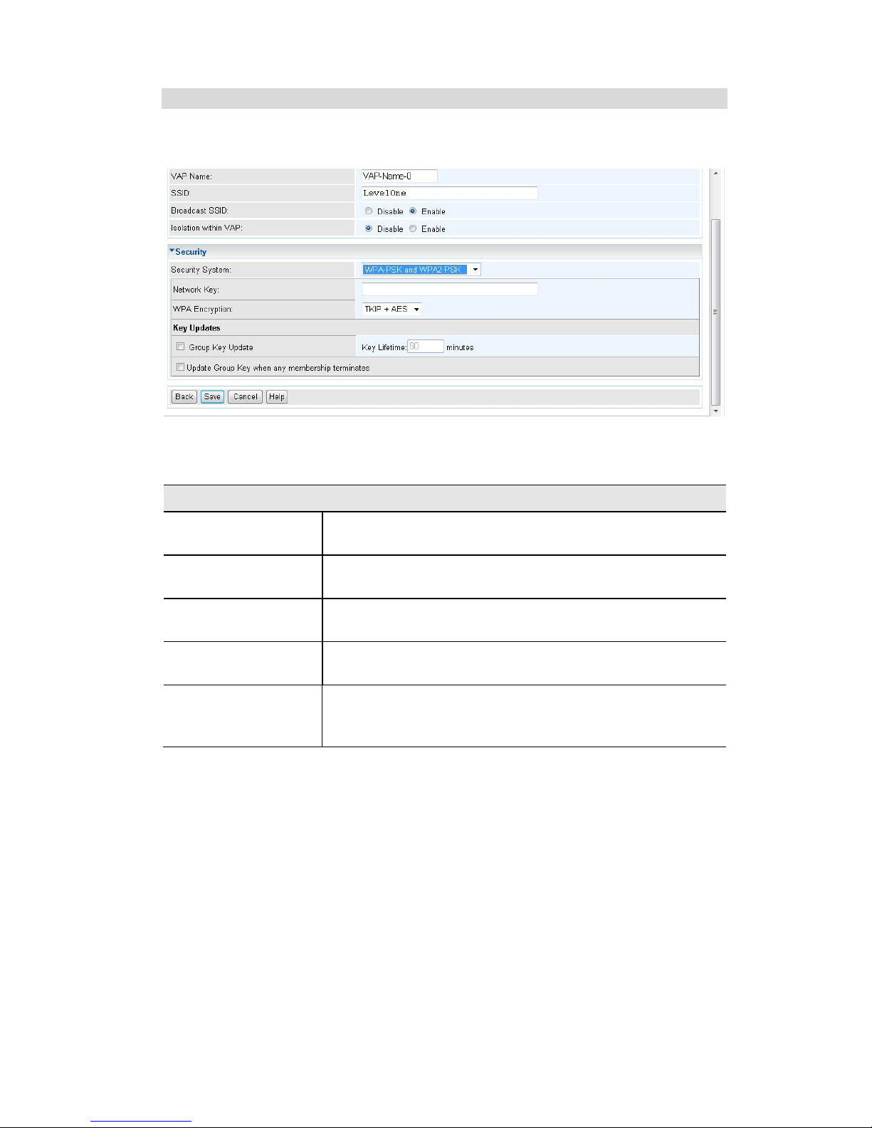
Security Settings - WPA2-PSK
This is a further development of WPA-PSK, and offers even greater security, using the
AES (Advanced Encryption Standard) method of encryption.
Figure 15: WPA2-PSK Wireless Security Screen
Data - WPA2-PSK Screen
WPA2-PSK
Network Key
Enter the key value. Data is encrypted using a 256Bit key
derived from this key. Other Wireless Stations must use the
same key.
WPA Encryption
The encryption method is AES. Wireless Stations must also
use AES.
Group Key Update
This refers to the key used for broadcast transmissions.
Enable this if you want the keys to be updated regularly.
Key Lifetime
This field determines how often the Group key is dynamically updated. Enter the desired value.
Update Group key
when any membership terminates
If enabled, the Group key will be updated whenever any
member leaves the group or disassociates from the Access
Point.
Page 30
Wireless Access Point User Guide
26
Security Settings - WPA-PSK and WPA2-PSK
This method, sometimes called "Mixed Mode", allows clients to use EITHER WPAPSK (with TKIP) OR WPA2-PSK (with AES).
Figure 16: WPA-PSK and WPA2-PSK Wireless Security Screen
Data - WPA-PSK and WPA2-PSK Screen
WPA-PSK and WPA2-PSK
Network Key
Enter the key value. Data is encrypted using this key. Other
Wireless Stations must use the same key.
WPA Encryption
The encryption method is TKIP for WPA-PSK, and AES for
WPA2-PSK.
Group Key Update
This refers to the key used for broadcast transmissions.
Enable this if you want the keys to be updated regularly.
Key Lifetime
This field determines how often the Group key is dynamically updated. Enter the desired value.
Update Group key
when any membership terminates
If enabled, the Group key will be updated whenever any
member leaves the group or disassociates from the Access
Point.
Page 31
Access Point Setup
27
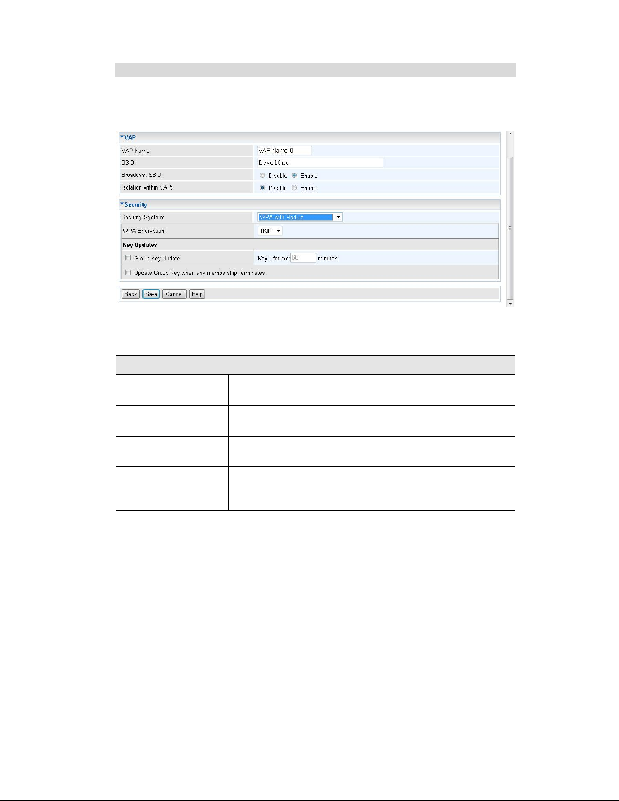
Security Settings - WPA with Radius
This version of WPA requires a Radius Server on your LAN to provide the client authentication according to the 802.1x standard. Data transmissions are encrypted using
the WPA standard.
Figure 17: WPA with Radius Wireless Security Screen
Data - WPA with Radius Screen
WPA with Radius
WPA Encryption
The encryption method is TKIP. Wireless Stations must
also use TKIP.
Group Key Update
This refers to the key used for broadcast transmissions.
Enable this if you want the keys to be updated regularly.
Key Lifetime
This field determines how often the Group key is dynamically updated. Enter the desired value.
Update Group key
when any membership terminates
If enabled, the Group key will be updated whenever any
member leaves the group or disassociates from the Access
Point.
Page 32
Wireless Access Point User Guide
28
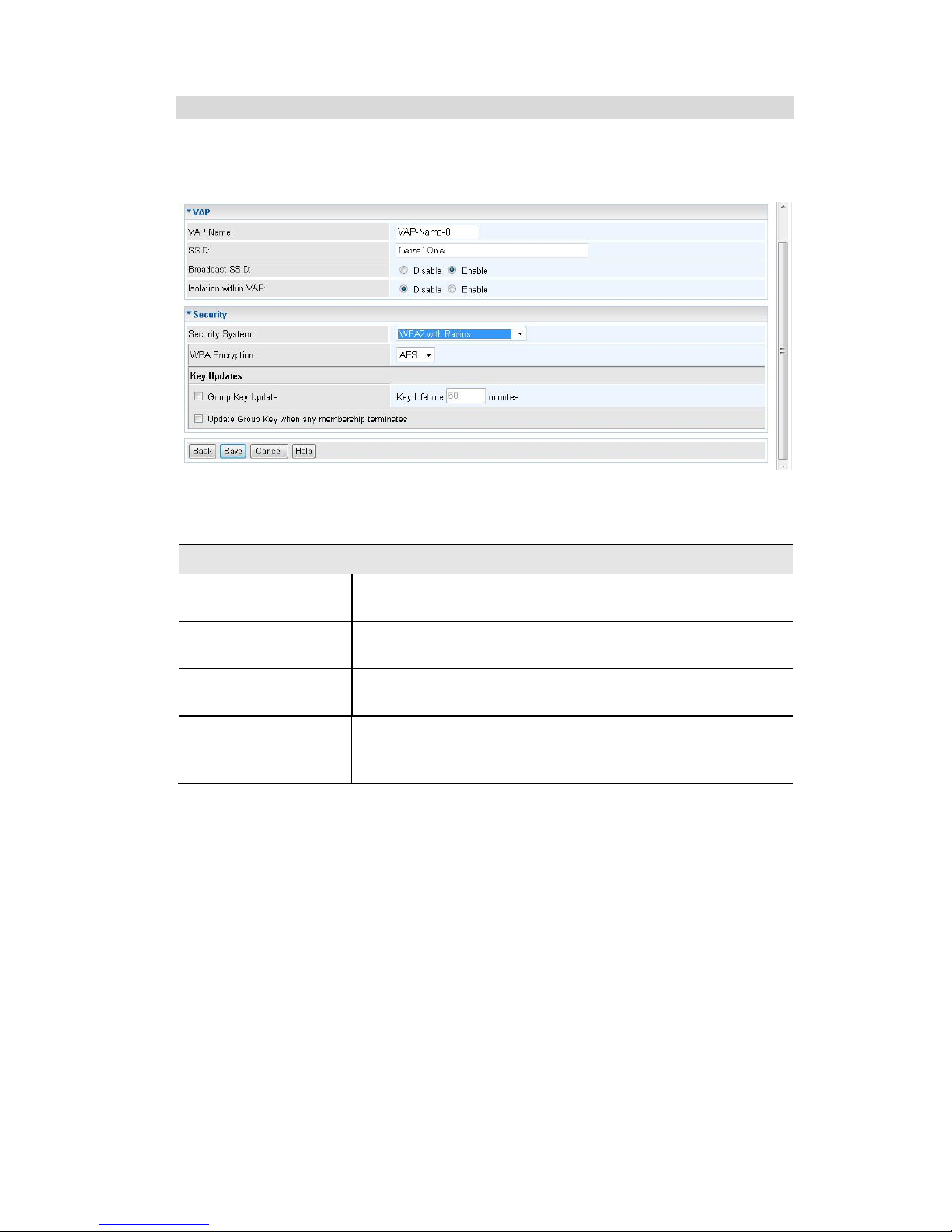
Security Settings - WPA2 with Radius
This version of WPA2 requires a Radius Server on your LAN to provide the client
authentication according to the 802.1x standard. Data transmissions are encrypted
using the WPA2 standard.
Figure 18: WPA2 with Radius Wireless Security Screen
Data - WPA2 with Radius Screen
WPA2 with Radius
WPA Encryption
The encryption method is AES. Wireless Stations must also
use AES.
Group Key Update
This refers to the key used for broadcast transmissions.
Enable this if you want the keys to be updated regularly.
Key Lifetime
This field determines how often the Group key is dynamically updated. Enter the desired value.
Update Group key
when any membership terminates
If enabled, the Group key will be updated whenever any
member leaves the group or disassociates from the Access
Point.
Page 33
Access Point Setup
29
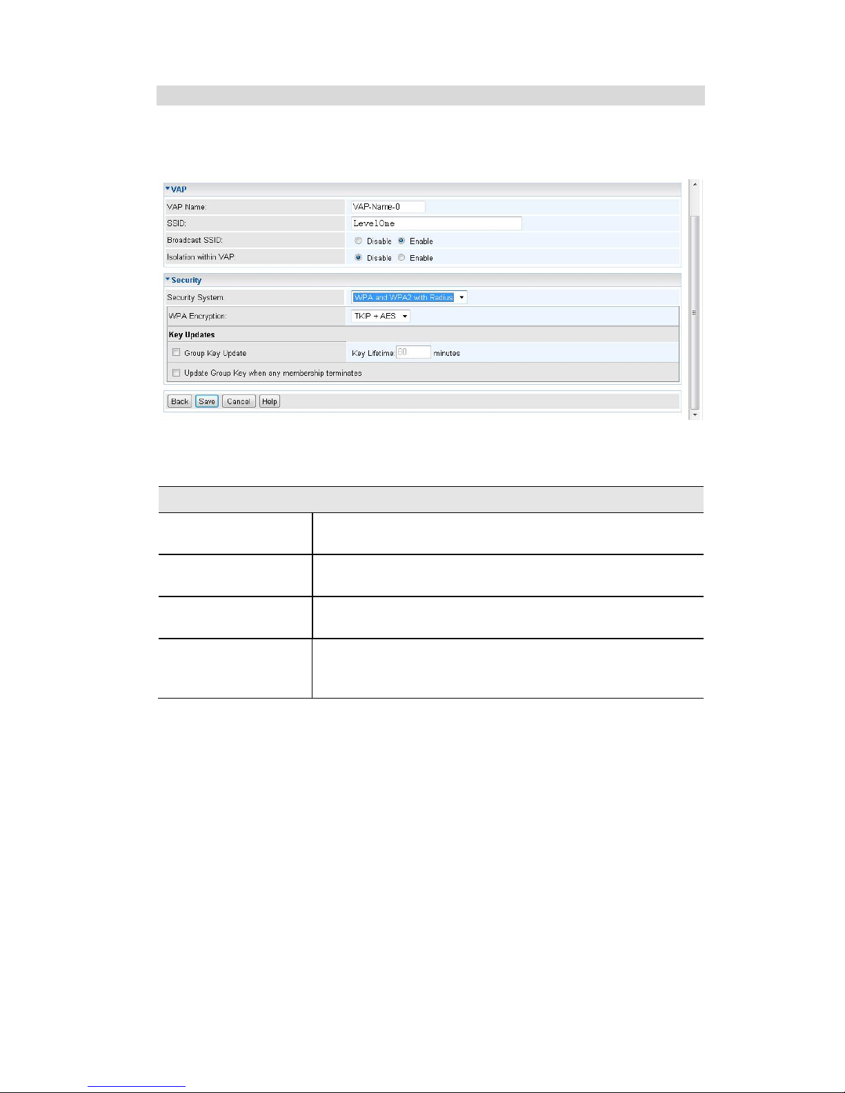
Security Settings - WPA and WPA2 with Radius
EITHER WPA or WPA2 require a Radius Server on your LAN to provide the client
authentication according to the 802.1x standard. Data transmissions are encrypted
using EITHER WPA or WPA2 standard.
Figure 19: WPA and WPA2 with Radius Wireless Security Screen
Data - WPA and WPA2 with Radius Screen
WPA and WPA2 with Radius
WPA Encryption
The encryption method is TKIP for WPA, and AES for
WPA2.
Group Key Update
This refers to the key used for broadcast transmissions.
Enable this if you want the keys to be updated regularly.
Key Lifetime
This field determines how often the Group key is dynamically updated. Enter the desired value.
Update Group key
when any membership terminates
If enabled, the Group key will be updated whenever any
member leaves the group or disassociates from the Access
Point.
Page 34
Wireless Access Point User Guide
30
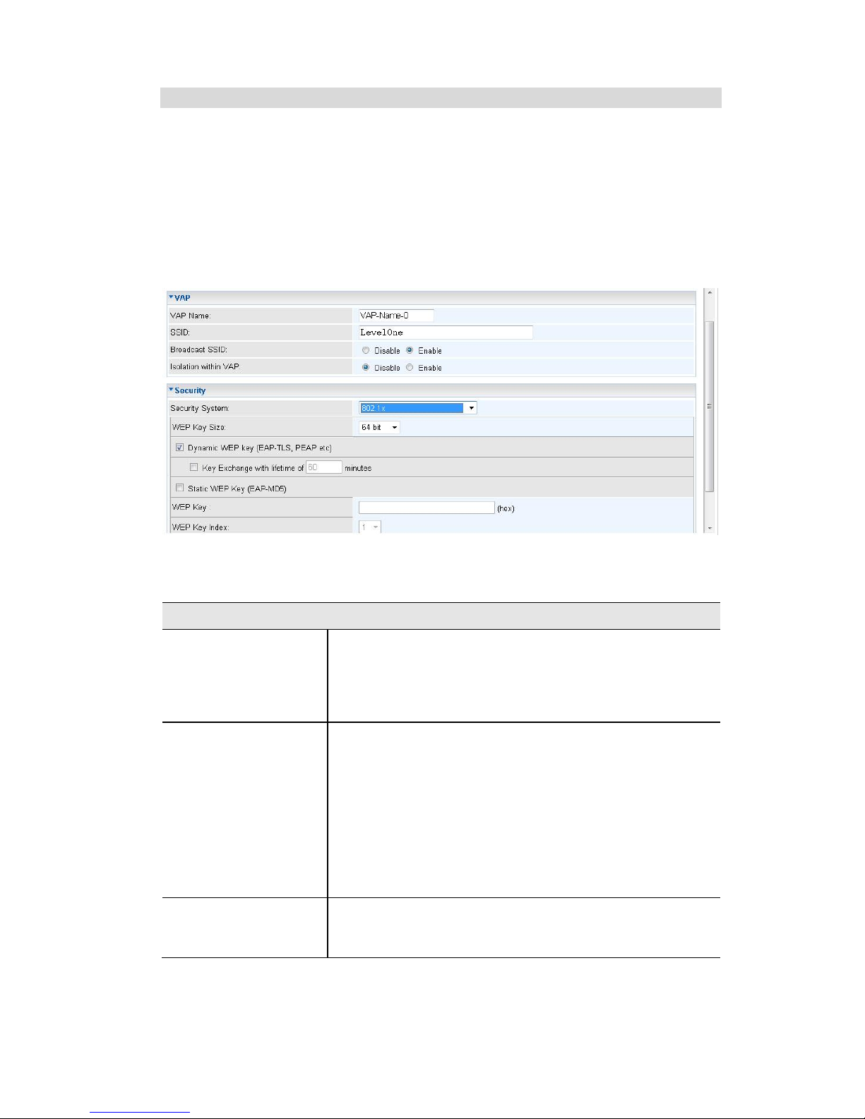
Security Settings - 802.1x
This uses the 802.1x standard for client authentication, and WEP for data encryption. If
this option is selected:
This Access Point must have a "client login" on the Radius Server.
Each user must have a "user login" on the Radius Server. Normally, a Certificate is
used to authenticate each user. See Chapter4 for details of user configuration.
Each user's wireless client must support 802.1x.
All data transmission is encrypted using the WEP standard. You only have to
select the WEP key size; the WEP key is automatically generated.
Figure 20: 802.1x Wireless Security Screen
Data - 802.1x Screen
802.1x
WEP Key Size
Select the desired option:
64 Bit - Keys are 10 Hex (5 ASCII) characters.
128 Bit - Keys are 26 Hex (13 ASCII) characters.
152 Bit - Keys are 32 Hex (16 ASCII) characters.
Dynamic WEP Key
Click this if you want the WEP keys to be automatically
generated.
The key exchange will be negotiated. The most widely
supported protocol is EAP-TLS.
The following Key Exchange setting determines how
often the keys are changed.
Both Dynamic and Static keys can be used simulta-
neously, allowing clients using either method to use
the Access Point.
Key Exchange
This setting if only available if using Dynamic WEP Keys. If
you want the Dynamic WEP keys to be updated regularly,
enable this and enter the desired lifetime (in minutes).
Page 35

Access Point Setup
31
Static WEP Key
(EAP-MD5)
Enable this if some wireless clients use a fixed (static)
WEP key, using EAP-MD5.
Note that both Dynamic and Static keys can be used
simultaneously, allowing clients using either method to use
the Access Point.
WEP Key
Enter the WEP key according to the WEP Key Size setting above. Wireless stations must use the same key.
WEP Key Index
Select the desired index value. Wireless stations must use
the same key index.
Page 36
Wireless Access Point User Guide
32
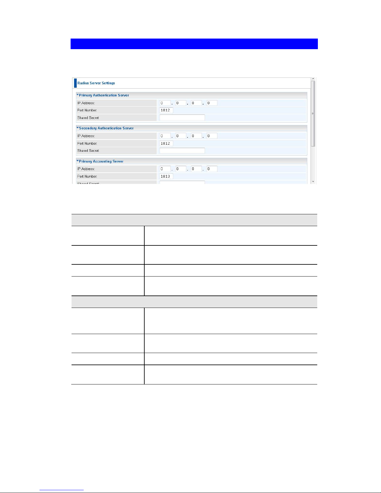
Radius Server Settings
Clicking the Radius Server Settings link on the Wireless menu will result in a screen
like the following.
Figure 21: Advanced Settings
Data - Radius Server Settings Screen
Authentication Server
Primary Authentication Server
Enter the name or IP address of the Radius Server on
your network.
Port Number
Enter the port number used for connections to the Radius
Server.
Shared Secret
Enter the key value to match the Radius Server.
Secondary Authentication Server
The Secondary Authentication Server will be used when
the Primary Authentication Server is not available.
Accounting Server
Primary Accounting
Server
Enter the IP address in the following fields if you want this
Access Point to send accounting data to the Radius Server.
Port Number
The port used by your Radius Server must be entered in
the field.
Shared Secret
Enter the key value to match the Radius Server.
Secondary Accounting Server
The Secondary Accounting Server will be used when the
Primary Accounting Server is not available.
Page 37
Access Point Setup
33
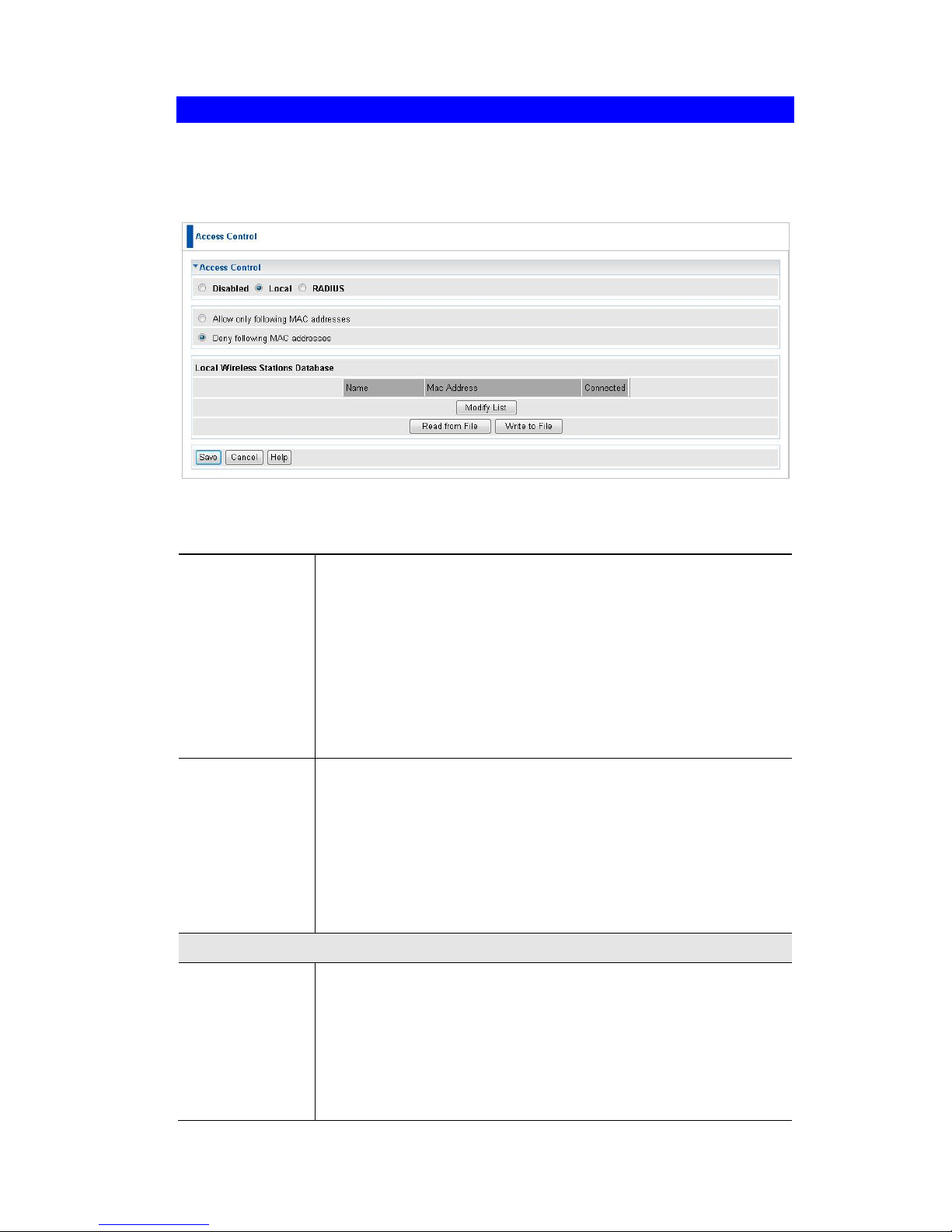
Access Control
This feature can be used to block access to your LAN by unknown or untrusted wireless stations.
Click Access Control on the Wireless menu to view a screen like the following.
Figure 22: Access Control Screen
Data - Access Control Screen
Access Control
Select the desired option, as required
Disabled - The Access Control feature is disabled.
Local - Select Allow only following MAC addresses or Deny
following MAC addresses.
Radius - The Access Point will use the MAC address table
located on the external Radius server on the LAN for Access
Control.
Warning ! Ensure your own PC is in the "Trusted Wireless
Stations" list before enabling this feature.
Local Trusted
Stations
This table lists any Wireless Stations you have designated as
"Trusted". If you have not added any stations, this table will be
empty. For each Wireless station, the following data is displayed:
Name - the name of the Wireless station.
MAC Address - the MAC or physical address of each
Wireless station.
Connected - this indicates whether or not the Wireless
station is currently associates with this Access Point.
Buttons
Modify List
To change the list of Trusted Stations (Add, Edit, or Delete a
Wireless Station or Stations), click this button. You will then see
the Trusted Wireless Stations screen, described below.
Read from File
To upload a list of Trusted Stations from a file on your PC, click
this button.
Write to File
To download the current list of Trusted Stations from the Access
Point to a file on your PC, click this button.
Page 38
Wireless Access Point User Guide
34
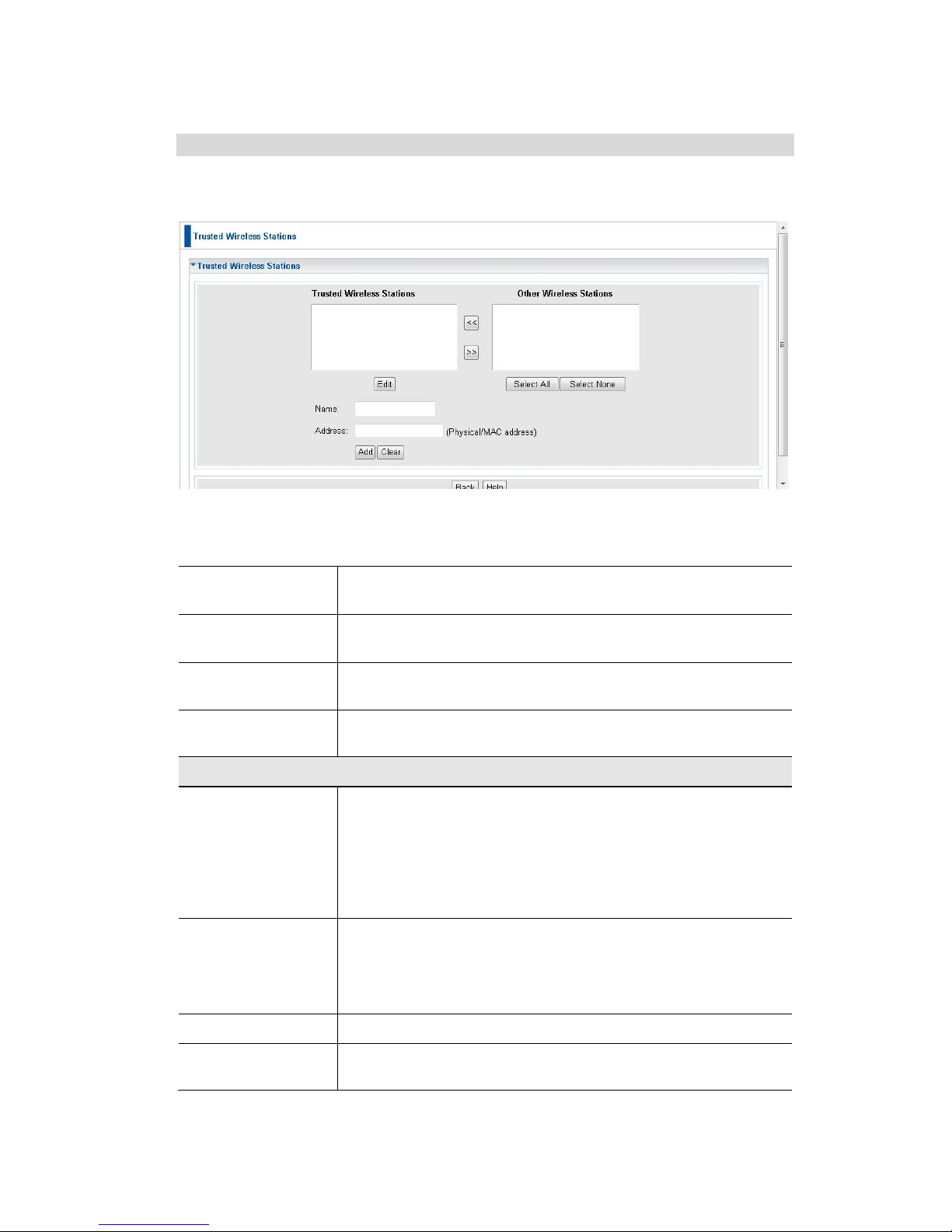
Trusted Wireless Stations
To change the list of trusted wireless stations, use the Modify List button on the
Access Control screen. You will see a screen like the sample below.
Figure 23: Trusted Wireless Stations
Data - Trusted Wireless Stations
Trusted Wireless
Stations
This lists any Wireless Stations which you have designated
as “Trusted”.
Other Wireless
Stations
This list any Wireless Stations detected by the Access Point,
which you have not designated as "Trusted".
Name
The name assigned to the Trusted Wireless Station. Use this
when adding or editing a Trusted Station.
Address
The MAC (physical) address of the Trusted Wireless Station.
Use this when adding or editing a Trusted Station.
Buttons
<<
Add a Trusted Wireless Station to the list (move from the
"Other Stations" list).
Select an entry (or entries) in the "Other Stations" list, and
click the " << " button.
Enter the Address (MAC or physical address) of the
wireless station, and click the "Add " button.
>>
Delete a Trusted Wireless Station from the list (move to the
"Other Stations" list).
Select an entry (or entries) in the "Trusted Stations" list.
Click the " >> " button.
Select All
Select all of the Stations listed in the "Other Stations" list.
Select None
De-select any Stations currently selected in the "Other Stations" list.
Page 39

Access Point Setup
35
Edit
To change an existing entry in the "Trusted Stations" list,
select it and click this button.
1. Select the Station in the "Trusted Station" list.
2. Click the "Edit" button. The address will be copied to the
"Address" field, and the "Add" button will change to "Update".
3. Edit the address (MAC or physical address) as required.
4. Click "Update" to save your changes.
Add
To add a Trusted Station which is not in the "Other Wireless
Stations" list, enter the required data and click this button.
Clear
Clear the Name and Address fields.
Page 40
Wireless Access Point User Guide
36
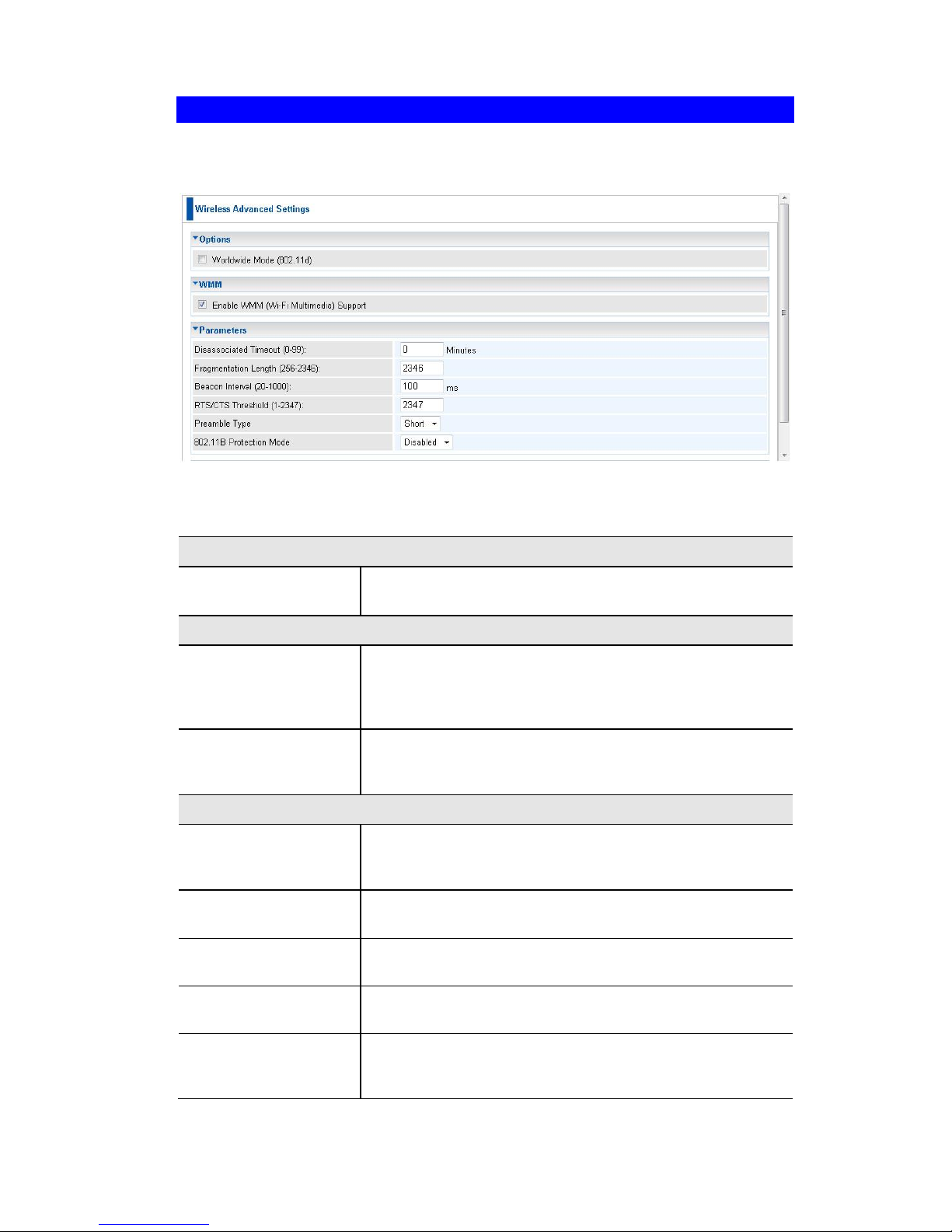
Advanced Settings
Clicking the Advanced Settings link on the Wireless menu will result in a screen like
the following.
Figure 24: Advanced Settings
Data - Advanced Settings Screen
Options
Worldwide Mode
(802.11d)
Enable this setting if you wish to use this mode, and your
Wireless stations support this mode.
WMM
Enable WMM Support
Check this to enable WMM (Wi-Fi Multimedia) support in
the Access Point. If WMM is also supported by your wireless clients, voice and multimedia traffic will be given a
higher priority than other traffic.
No Acknowledgement
If enabled, then WMM acknowledgement is disabled.
Depending on the environment, disabling acknowledgement may increase throughput slightly.
Parameters
Disassociated Timeout
This determines how quickly a Wireless Station will be
considered "Disassociated" with this AP, when no traffic is
received. Enter the desired time period.
Fragmentation
Length
Enter the preferred setting between 256 and 2346. Normally, this can be left at the default value.
Beacon Interval
Enter the preferred setting between 20 and 1000. Normally, this can be left at the default value.
RTS/CTS Threshold
Enter the preferred setting between 1 and 2347. Normally,
this can be left at the default value.
Preamble Type
Select the desired option. The default is "Long". The
"Short" setting takes less time when used in a good environment.
Page 41

Access Point Setup
37
802.11b Protection
Mode
The Protection system is intended to prevent older
802.11b devices from interfering with 802.11g transmis-
sions. (Older 802.11b devices may not be able to detect
that a 802.11g transmission is in progress.) Normally, this
should be left at "Auto".
Page 42
Wireless Access Point User Guide
38
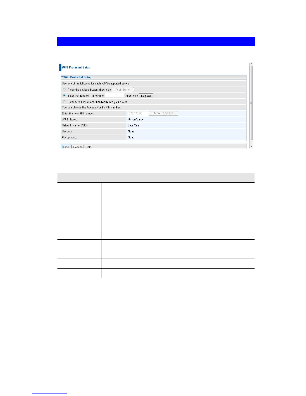
Wi-Fi Protected Setup
Click WiFi Protected Setup on the Wireless menu to view a screen like the following:
Figure 25: WPS Screen
Data - WPS Screen
WPS
Use one of the
following..
If the first option is selected, press the WPS button on the
client device, then click the Push button.
If the second option is selected, enter the PIN code from the
client device in this field and click Register button.
If the third option is selected, enter the displayed PIN code to
the client device.
Change AP
Settings
Enter the desired pin value manually or click the Auto generate
button to have the new pin code displayed in the field.
WPS Status
It displays the current WPS status.
Network Name
It displays the network name in use.
Security
The current security method is displayed.
Passphrase
The current status of Passphrase is displayed.
Page 43

39
Chapter 4
PC and Server Configuration
This Chapter details the PC Configuration required for each PC on the
local LAN.
Overview
All Wireless Stations need to have settings which match the Wireless Access Point.
These settings depend on the mode in which the Access Point is being used.
If using WEP or WPA-PSK, it is only necessary to ensure that each Wireless
station's settings match those of the Wireless Access Point, as described below.
For 802.1x modes, configuration is much more complex. The Radius Server must
be configured correctly, and setup of each Wireless station is also more complex.
Using WEP
For each of the following items, each Wireless Station must have the same settings as
the Wireless Access Point.
Mode
On each PC, the mode must be set to Infrastructure.
SSID (ESSID)
This must match the value used on the Wireless Access Point.
The default value is wireless
Note! The SSID is case sensitive.
Wireless
Security
Each Wireless station must be set to use WEP data encryp-
tion.
The Key size (64 bit, 128 bit, 152 bit) must be set to match the
Access Point.
The keys values on the PC must match the key values on the
Access Point.
Note:
On some systems, the key sizes may be shown as 40bit, 104bit,
and 128bit instead of 64 bit, 128 bit and 152bit. This difference
arises because the key input by the user is 24 bits less than the
key size used for encryption.
4
Page 44

Wireless Access Point User Guide
40
Using WPA-PSK/WPA2-PSK
For each of the following items, each Wireless Station must have the same settings as
the Wireless Access Point.
Mode
On each PC, the mode must be set to Infrastructure.
SSID (ESSID)
This must match the value used on the Wireless Access Point.
The default value is wireless
Note! The SSID is case sensitive.
Wireless
Security
On each client, Wireless security must be set to WPA-PSK.
The Pre-shared Key entered on the Access Point must also
be entered on each Wireless client.
The Encryption method (e.g. TKIP, AES) must be set to
match the Access Point.
Page 45

PC and Server Configuration
41
Using WPA-Enterprise
This is the most secure and most complex system.
WPA-Enterprise mode provides greater security and centralized management, but it is
more complex to configure.
Wireless Station Configuration
For each of the following items, each Wireless Station must have the same settings as
the Wireless Access Point.
Mode
On each PC, the mode must be set to Infrastructure.
SSID (ESSID)
This must match the value used on the Wireless Access Point.
The default value is wireless
Note! The SSID is case sensitive.
802.1x
Authentication
Each client must obtain a Certificate which is used for authentication for the Radius Server.
802.1x
Encryption
Typically, EAP-TLS is used. This is a dynamic key system, so keys
do NOT have to be entered on each Wireless station.
However, you can also use a static WEP key (EAP-MD5); the
Wireless Access Point supports both methods simultaneously.
Radius Server Configuration
If using WPA-Enterprise mode, the Radius Server on your network must be configured as follow:
It must provide and accept Certificates for user authentication.
There must be a Client Login for the Wireless Access Point itself.
The Wireless Access Point will use its Default Name as its Client Login name.
(However, your Radius server may ignore this and use the IP address instead.)
The Shared Key, set on the Security Screen of the Access Point, must match
the Shared Secret value on the Radius Server.
Encryption settings must be correct.
Page 46

Wireless Access Point User Guide
42
802.1x Server Setup (Windows 2000 Server)
This section describes using Microsoft Internet Authentication Server as the Radius
Server, since it is the most common Radius Server available that supports the EAPTLS authentication method.
The following services on the Windows 2000 Domain Controller (PDC) are also required:
dhcpd
dns
rras
webserver (IIS)
Radius Server (Internet Authentication Service)
Certificate Authority
Windows 2000 Domain Controller Setup
1. Run dcpromo.exe from the command prompt.
2. Follow all of the default prompts, ensure that DNS is installed and enabled during
installation.
Services Installation
1. Select the Control Panel - Add/Remove Programs.
2. Click Add/Remove Windows Components from the left side.
3. Ensure that the following components are activated (selected):
Certificate Services. After enabling this, you will see a warning that the com-
puter cannot be renamed and joined after installing certificate services. Select
Yes to select certificate services and continue
World Wide Web Server. Select World Wide Web Server on the Internet In-
formation Services (IIS) component.
From the Networking Services category, select Dynamic Host Configuration
Protocol (DHCP), and Internet Authentication Service (DNS should already be
selected and installed).
Page 47
PC and Server Configuration
43
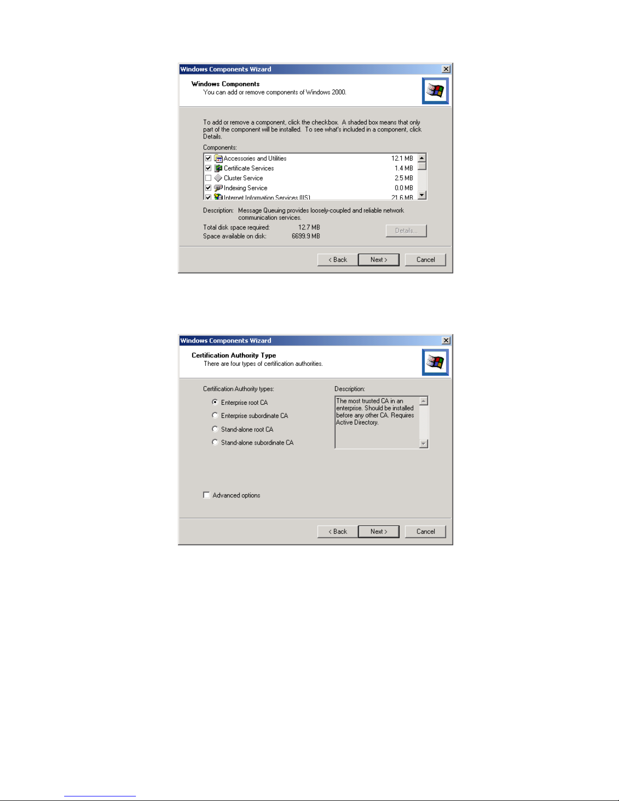
Figure 26: Components Screen
4. Click Next.
5. Select the Enterprise root CA, and click Next.
Figure 27: Certification Screen
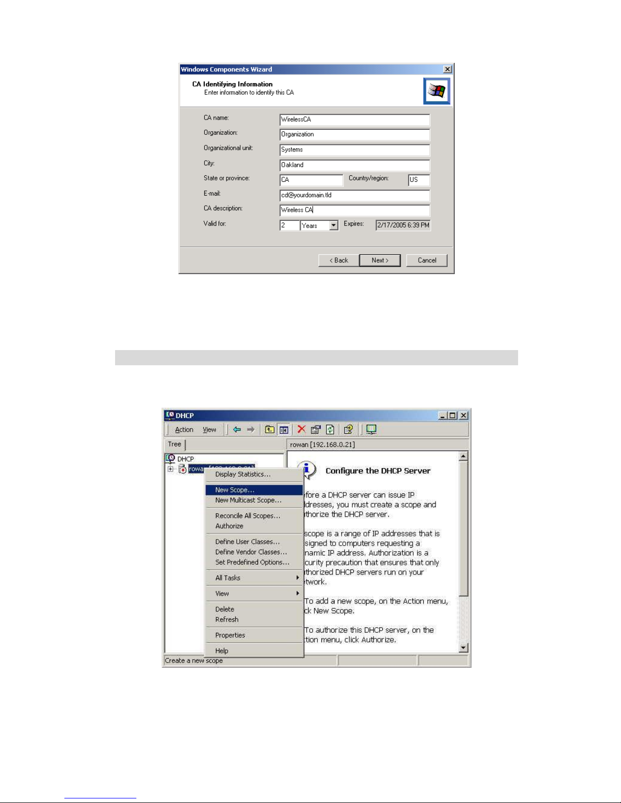
6. Enter the information for the Certificate Authority, and click Next.
Page 48
Wireless Access Point User Guide
44
Figure 28: CA Screen
7. Click Next if you don't want to change the CA's configuration data.
8. Installation will warn you that Internet Information Services are running, and must
be stopped before continuing. Click Ok, then Finish.
DHCP server configuration
1. Click on the Start - Programs - Administrative Tools - DHCP
2. Right-click on the server entry as shown, and select New Scope.
Figure 29: DHCP Screen
3. Click Next when the New Scope Wizard Begins.
4. Enter the name and description for the scope, click Next.
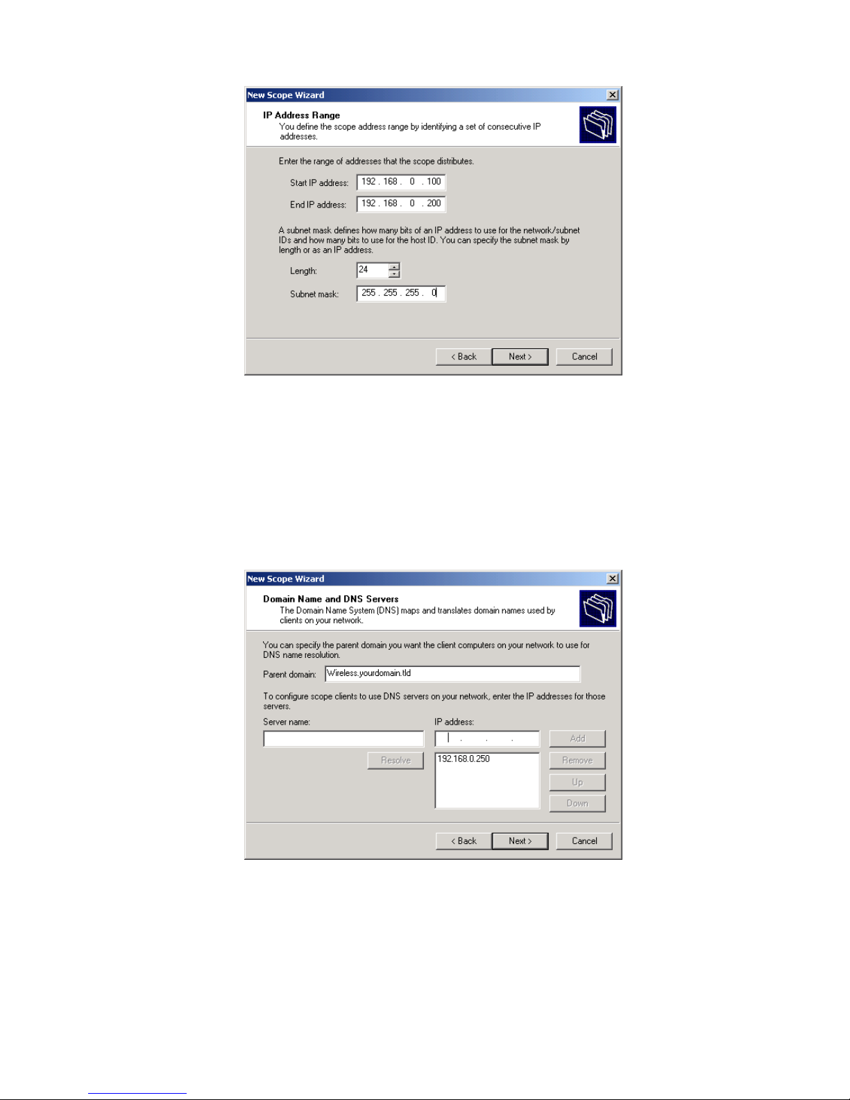
5. Define the IP address range. Change the subnet mask if necessary. Click Next.
Page 49
PC and Server Configuration
45
Figure 30:IP Address Screen
6. Add exclusions in the address fields if required. If no exclusions are required,
leave it blank. Click Next.
7. Change the Lease Duration time if preferred. Click Next.
8. Select Yes, I want to configure these options now, and click Next.
9. Enter the router address for the current subnet. The router address may be left
blank if there is no router. Click Next.
10. For the Parent domain, enter the domain you specified for the domain controller
setup, and enter the server's address for the IP address. Click Next.
Figure 31: DNS Screen
11. If you don't want a WINS server, just click Next.
12. Select Yes, I want to activate this scope now. Click Next, then Finish.
13. Right-click on the server, and select Authorize. It may take a few minutes to complete.
Page 50
Wireless Access Point User Guide
46
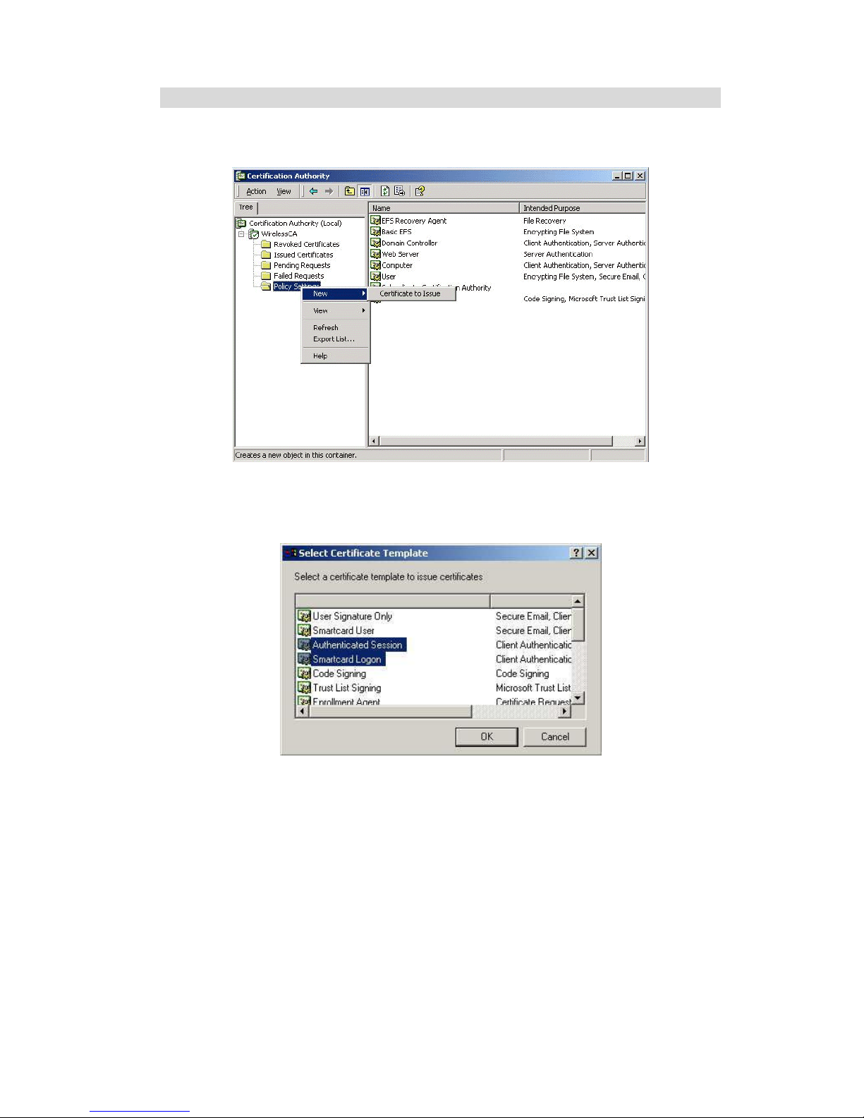
Certificate Authority Setup
1. Select Start - Programs - Administrative Tools - Certification Authority.
2. Right-click Policy Settings, and select New - Certificate to Issue.
Figure 32: Certificate Authority Screen
3. Select Authenticated Session and Smartcard Logon (select more than one by
holding down the Ctrl key). Click OK.
Figure 33: Template Screen
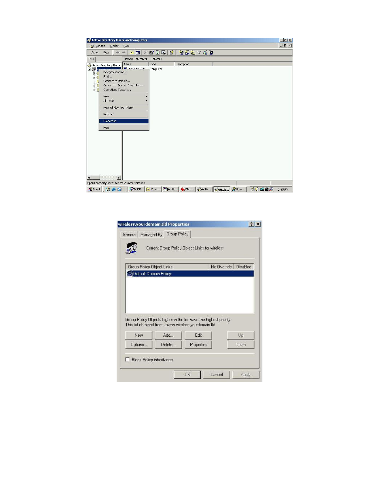
4. Select Start - Programs - Administrative Tools - Active Directory Users and Computers.
5. Right-click on your active directory domain, and select Properties.
Page 51
PC and Server Configuration
47
Figure 34: Active Directory Screen
6. Select the Group Policy tab, choose Default Domain Policy then click Edit.
Figure 35: Group Policy Tab
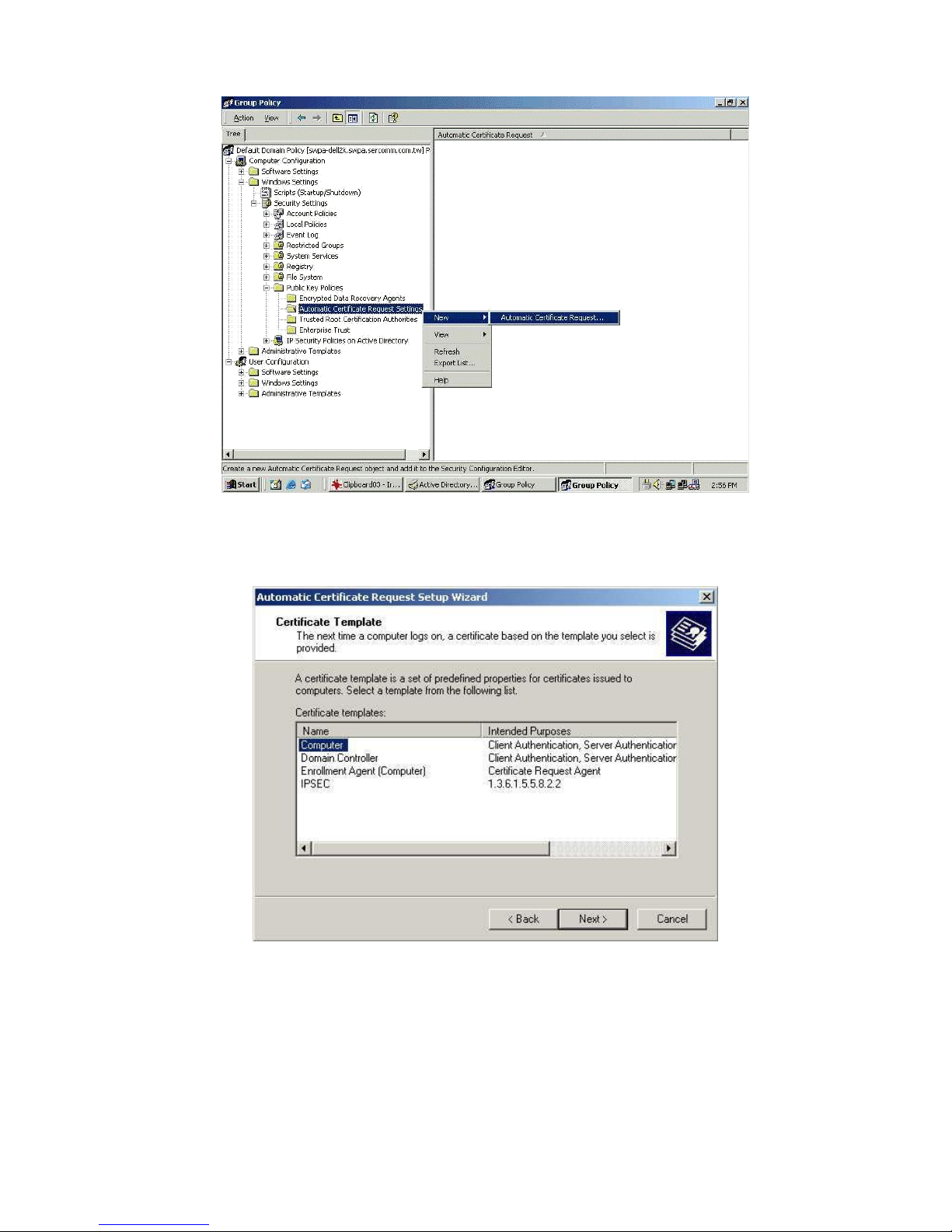
7. Select Computer Configuration - Windows Settings - Security Settings - Public Key
Policies, right-click Automatic Certificate Request Settings - New - Automatic Certificate Request.
Page 52
Wireless Access Point User Guide
48
Figure 36: Group Policy Screen
8. When the Certificate Request Wizard appears, click Next.
9. Select Computer, then click Next.
Figure 37: Certificate Template Screen
10. Ensure that your certificate authority is checked, then click Next.
11. Review the policy change information and click Finish.
12. Click Start - Run, type cmd and press enter.
Enter secedit /refreshpolicy machine_policy
This command may take a few minutes to take effect.
Page 53

PC and Server Configuration
49
Internet Authentication Service (Radius) Setup
1. Select Start - Programs - Administrative Tools - Internet Authentication Service
2. Right-click on Clients, and select New Client.
Figure 38: Service Screen
3. Enter a name for the access point, click Next.
4. Enter the address or name of the Wireless Access Point, and set the shared
secret, as entered on the Security Settings of the Wireless Access Point.
5. Click Finish.
6. Right-click on Remote Access Policies, select New Remote Access Policy.
7. Assuming you are using EAP-TLS, name the policy eap-tls, and click Next.
8. Click Add...
If you don't want to set any restrictions and a condition is required, select Day-And-
Time-Restrictions, and click Add...
Figure 39: Attribute Screen
9. Click Permitted, then OK. Select Next.
10. Select Grant remote access permission. Click Next.
Page 54
Wireless Access Point User Guide
50
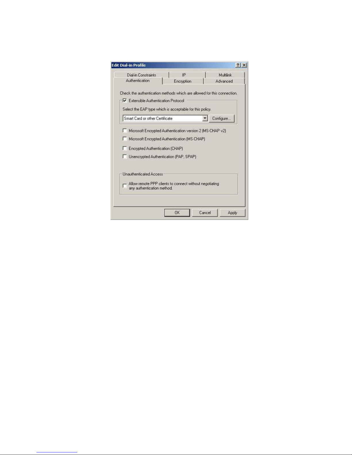
11. Click Edit Profile... and select the Authentication tab. Enable Extensible Authentication Protocol, and select Smart Card or other Certificate. Deselect other
authentication methods listed. Click OK.
Figure 40: Authentication Screen
12. Select No if you don't want to view the help for EAP. Click Finish.
Page 55
PC and Server Configuration
51
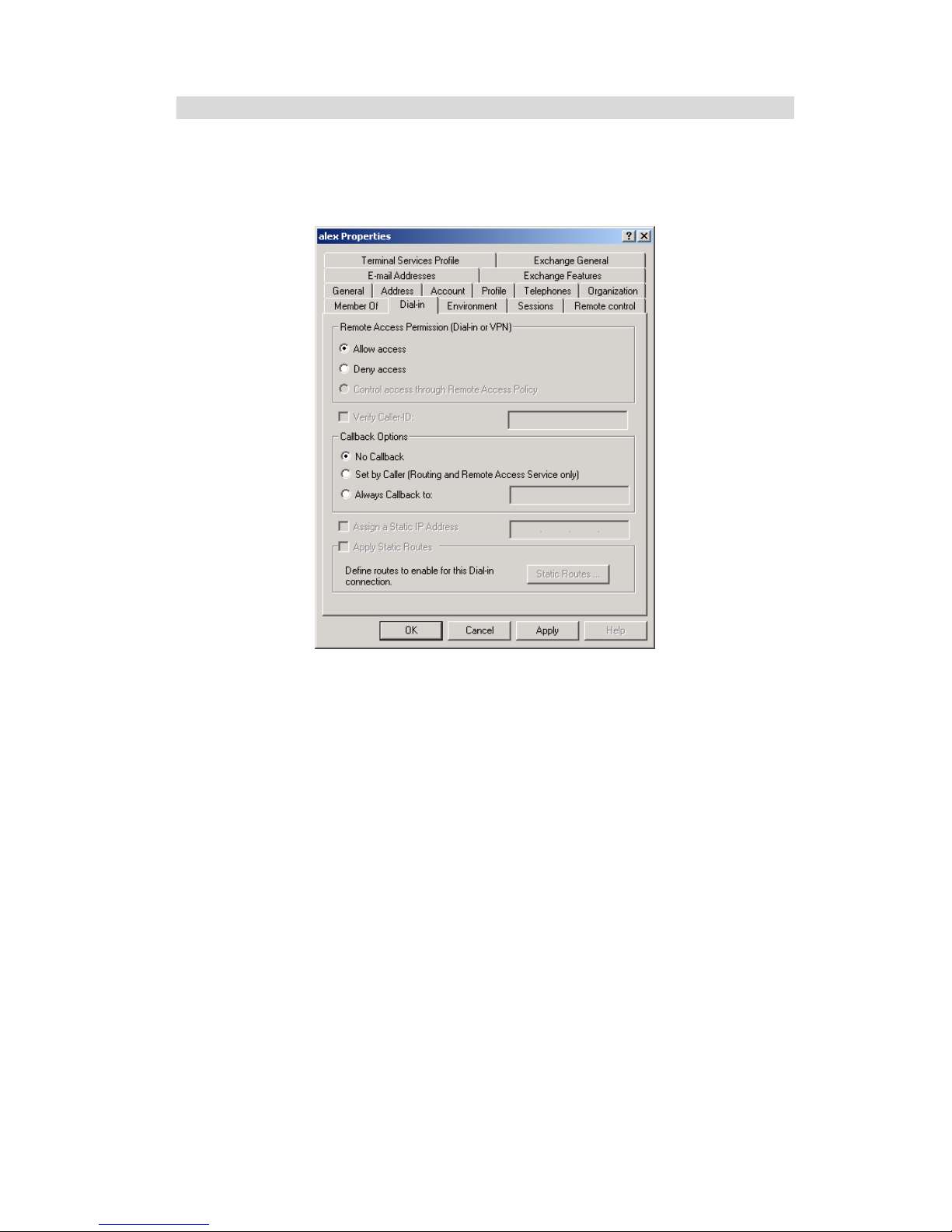
Remote Access Login for Users
1. Select Start - Programs - Administrative Tools- Active Directory Users and Computers.
2. Double click on the user who you want to enable.
3. Select the Dial-in tab, and enable Allow access. Click OK.
Figure 41: Dial-in Screen
Page 56
Wireless Access Point User Guide
52
802.1x Client Setup on Windows XP
Windows XP ships with a complete 802.1x client implementation. If using Windows
2000, you can install SP3 (Service Pack 3) to gain the same functionality.
If you don't have either of these systems, you must use the 802.1x client software
provided with your wireless adapter. Refer to your vendor's documentation for setup
instructions.
The following instructions assume that:
You are using Windows XP
You are connecting to a Windows 2000 server for authentication.
You already have a login (User name and password) on the Windows 2000 server.
Client Certificate Setup
1. Connect to a network which doesn't require port authentication.
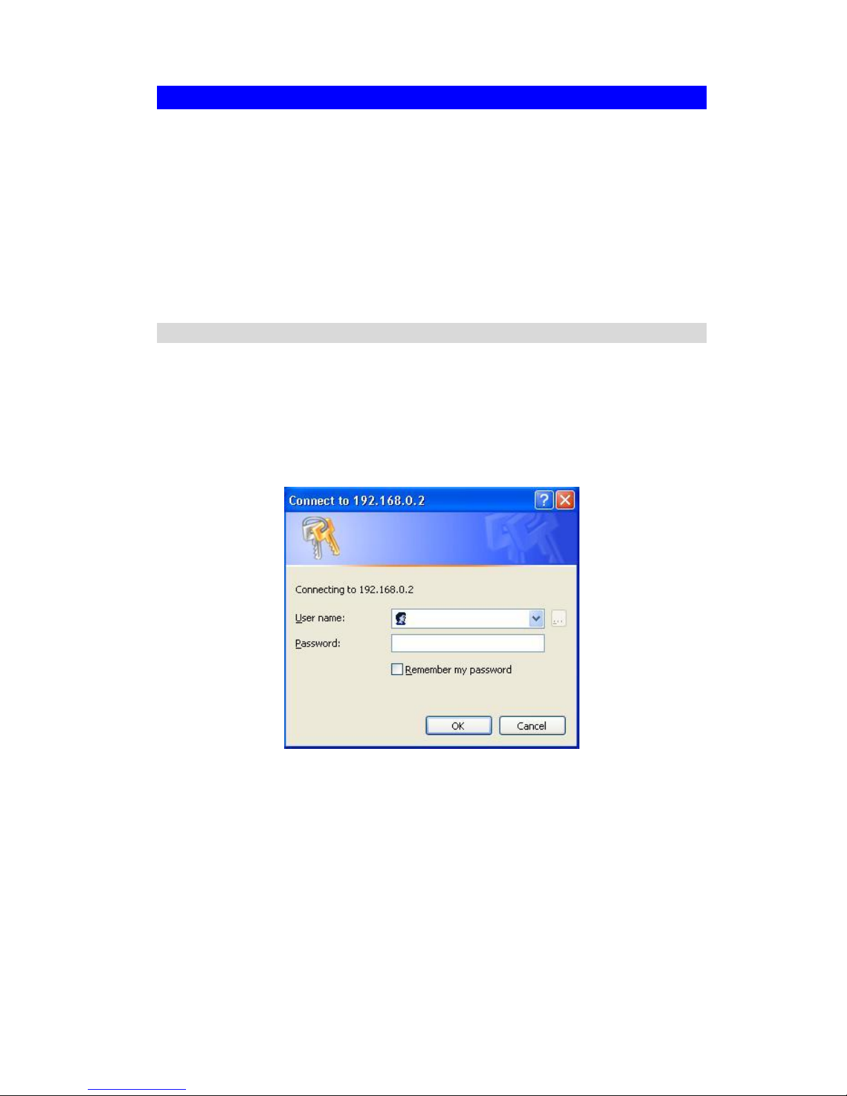
2. Start your Web Browser. In the Address box, enter the IP address of the Windows
2000 Server, followed by /certsrv
e.g
http://192.168.0.2/certsrv
3. You will be prompted for a user name and password. Enter the User name and
Password assigned to you by your network administrator, and click OK.
Figure 42: Connect Screen
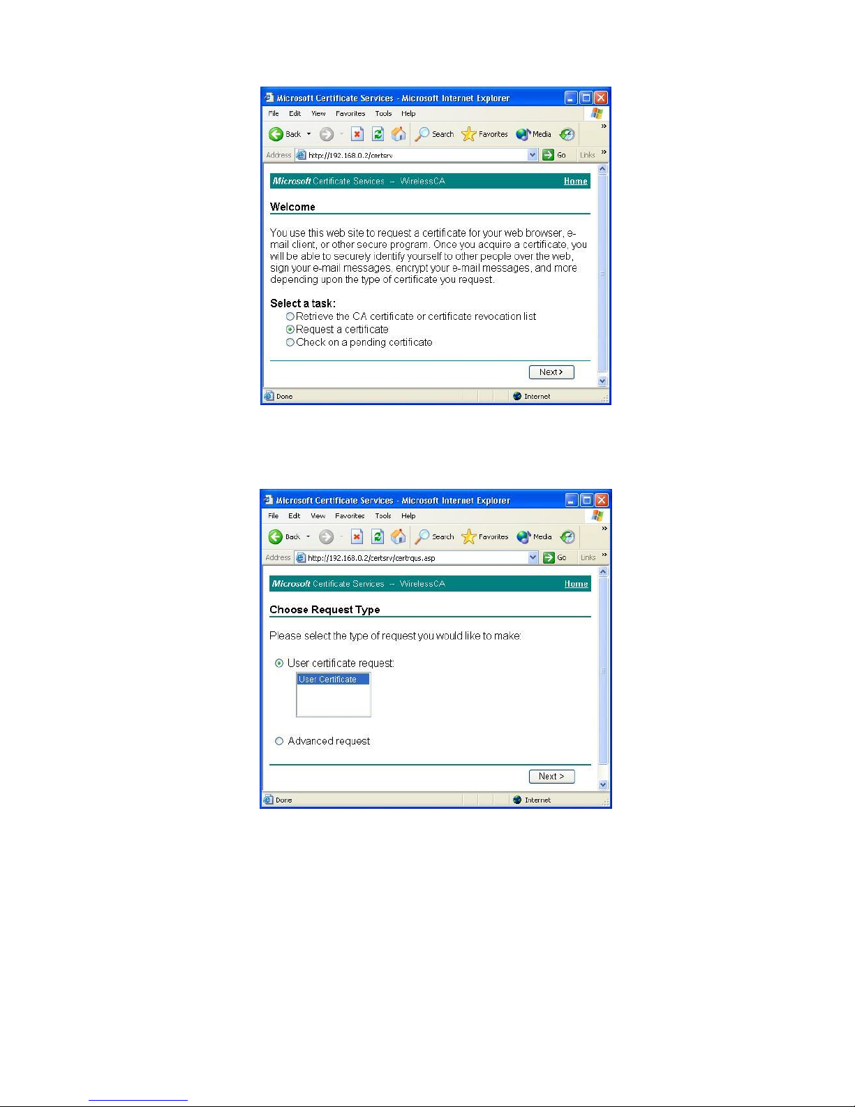
4. On the first screen (below), select Request a certificate, click Next.
Page 57
PC and Server Configuration
53
Figure 43: Wireless CA Screen
5. Select User certificate request and select User Certificate, the click Next.
Figure 44: Request Type Screen
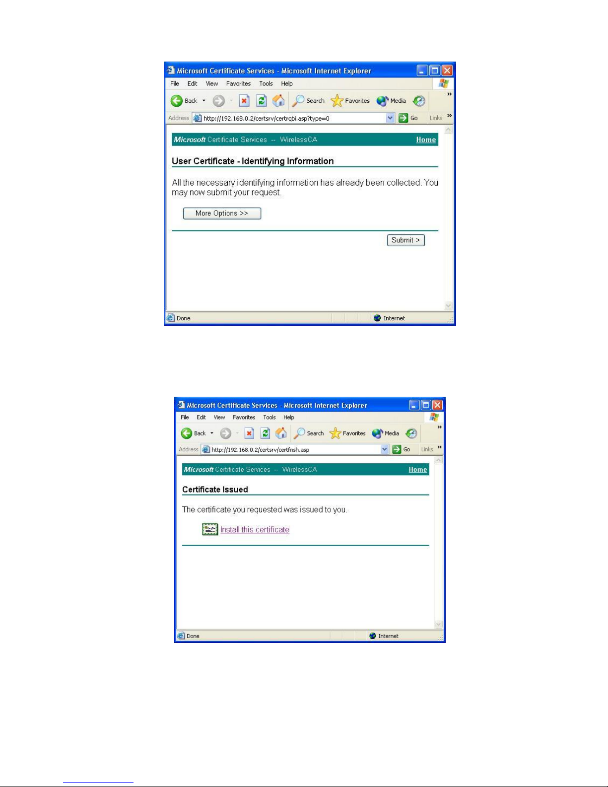
6. Click Submit.
Page 58
Wireless Access Point User Guide
54
Figure 45: Identifying Information Screen
7. A message will be displayed, then the certificate will be returned to you.
Click Install this certificate.
Figure 46:Certificate Issued Screen
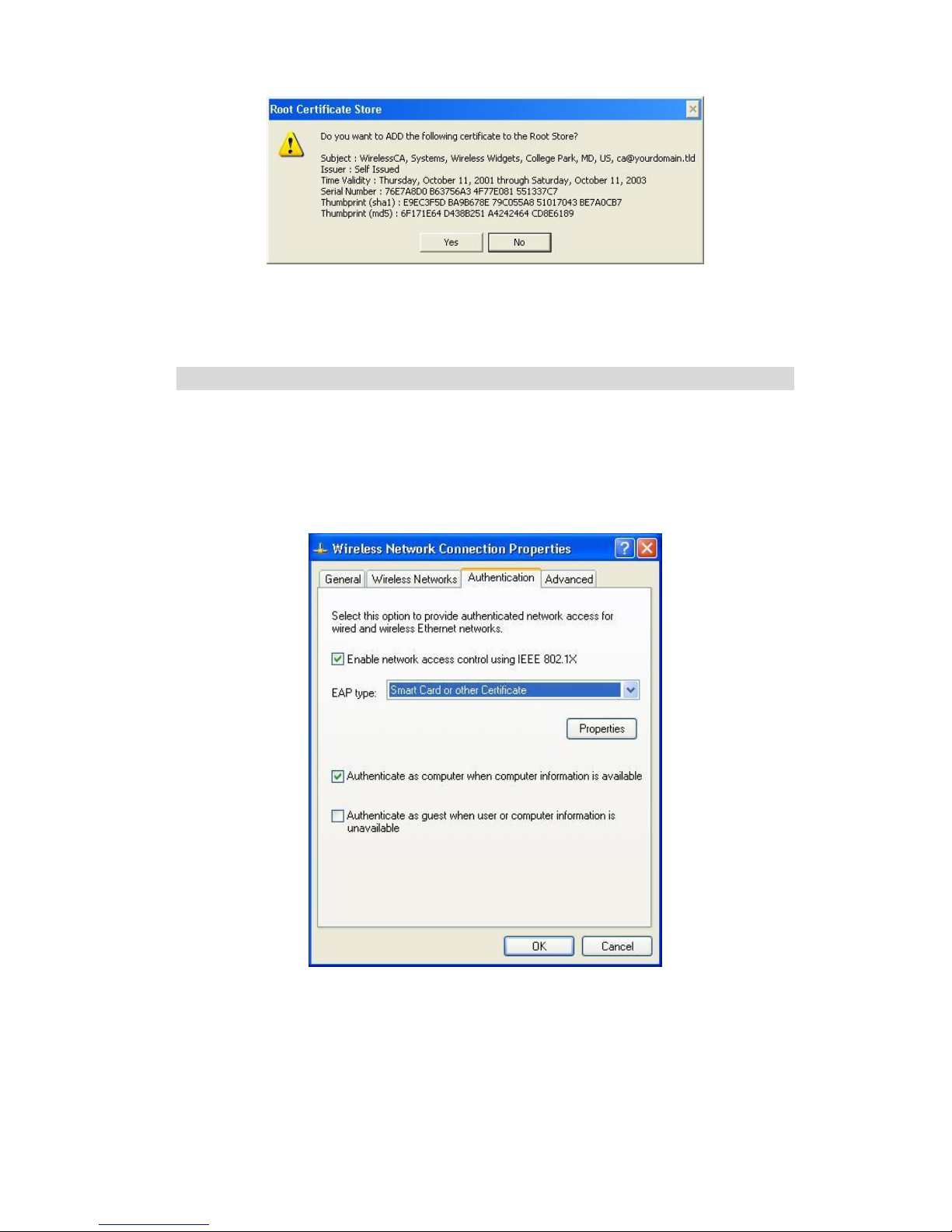
8. . You will receive a confirmation message. Click Yes.
Page 59
PC and Server Configuration
55
Figure 47: Root Certificate Screen
9. Certificate setup is now complete.
802.1x Authentication Setup
1. Open the properties for the wireless connection, by selecting Start - Control Panel
- Network Connections.
2. Right Click on the Wireless Network Connection, and select Properties.
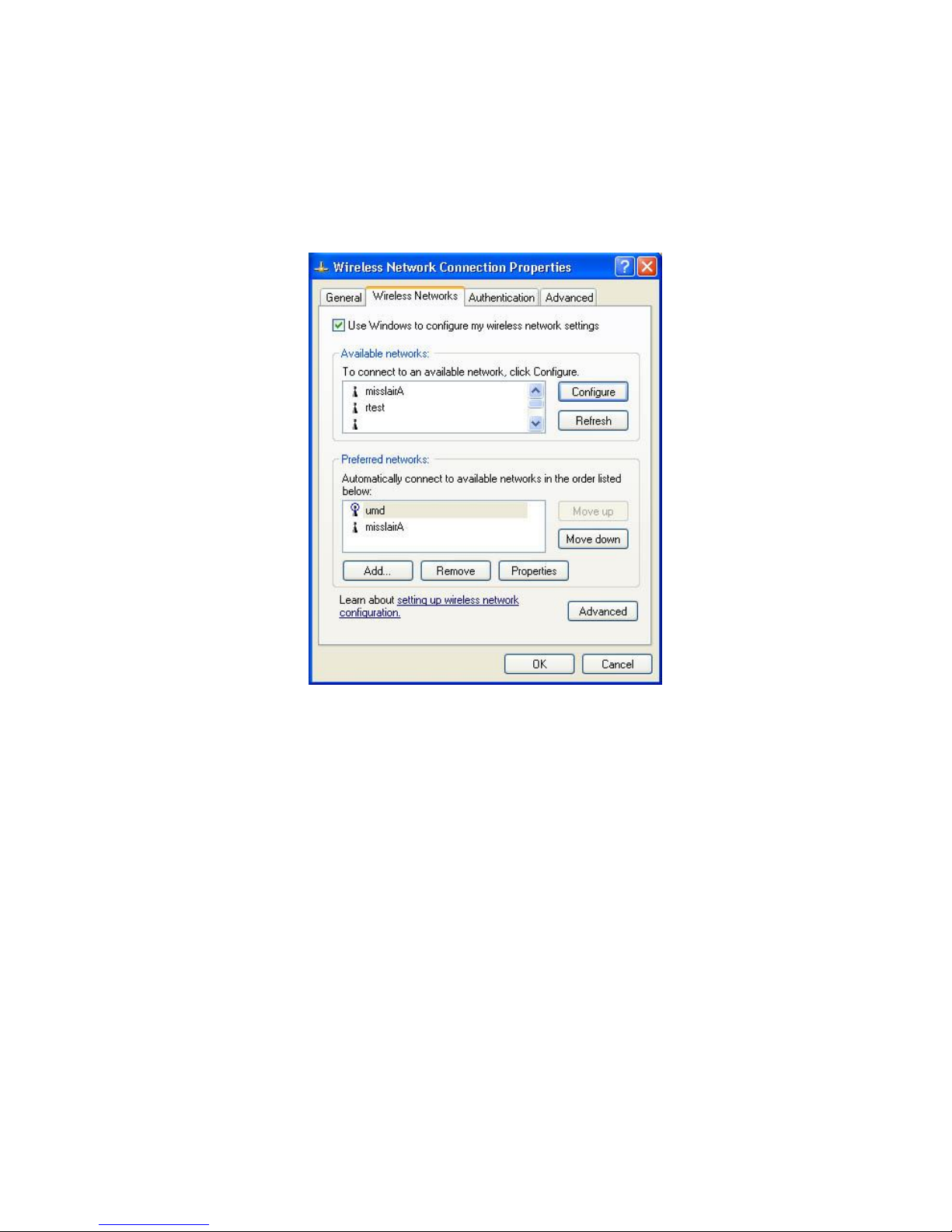
3. Select the Authentication Tab, and ensure that Enable network access control
using IEEE 802.1X is selected, and Smart Card or other Certificate is selected
from the EAP type.
Figure 48: Authentication Tab
Encryption Settings
The Encryption settings must match the APs (Access Points) on the Wireless network
you wish to join.
Windows XP will detect any available Wireless networks, and allow you to confi-
gure each network independently.
Page 60
Wireless Access Point User Guide
56
Your network administrator can advise you of the correct settings for each network.
802.1x networks typically use EAP-TLS. This is a dynamic key system, so there is
no need to enter key values.
Enabling Encryption
To enable encryption for a wireless network, follow this procedure:
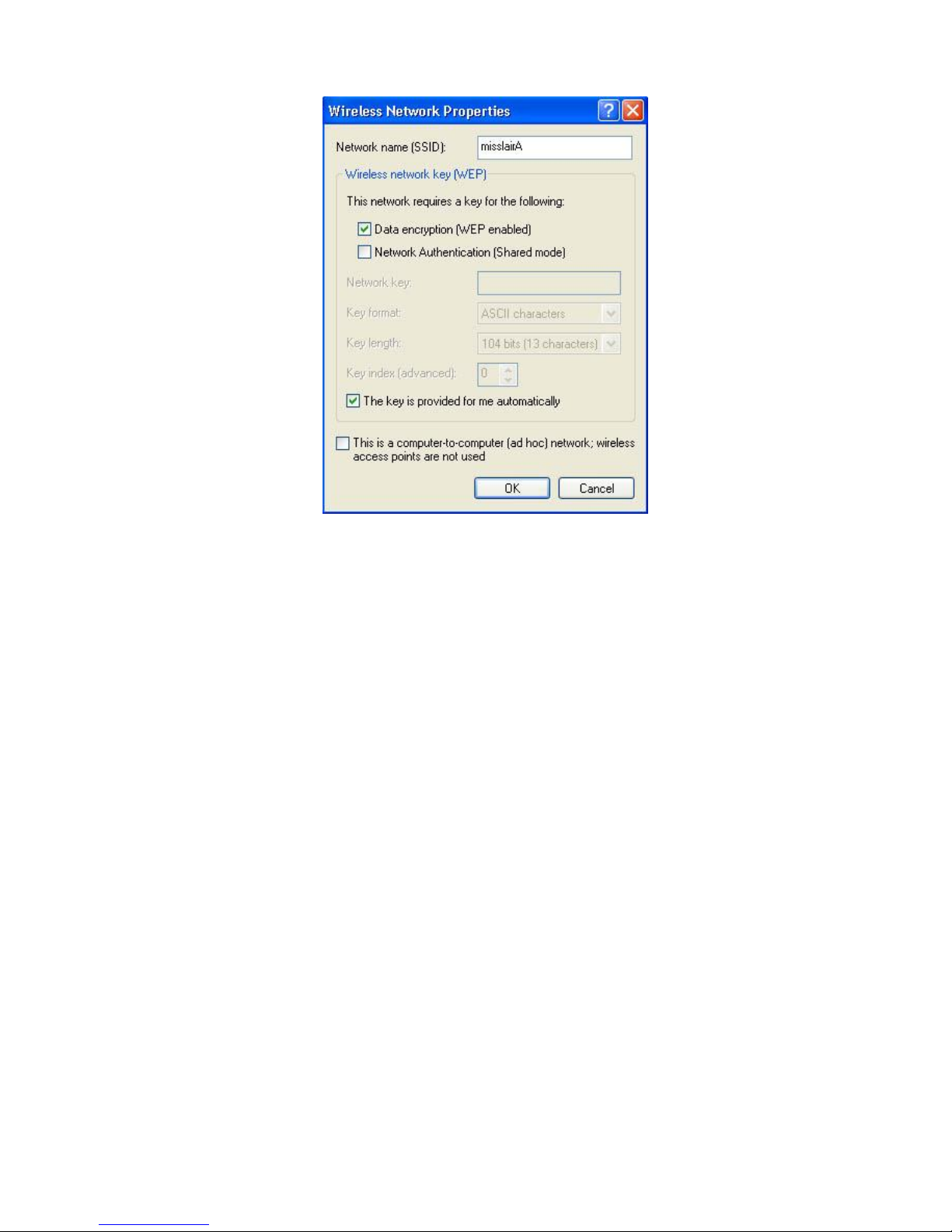
1. Click on the Wireless Networks tab.
Figure 49: Wireless Networks Screen
2. Select the wireless network from the Available Networks list, and click Configure.
3. Select and enter the correct values, as advised by your Network Administrator.
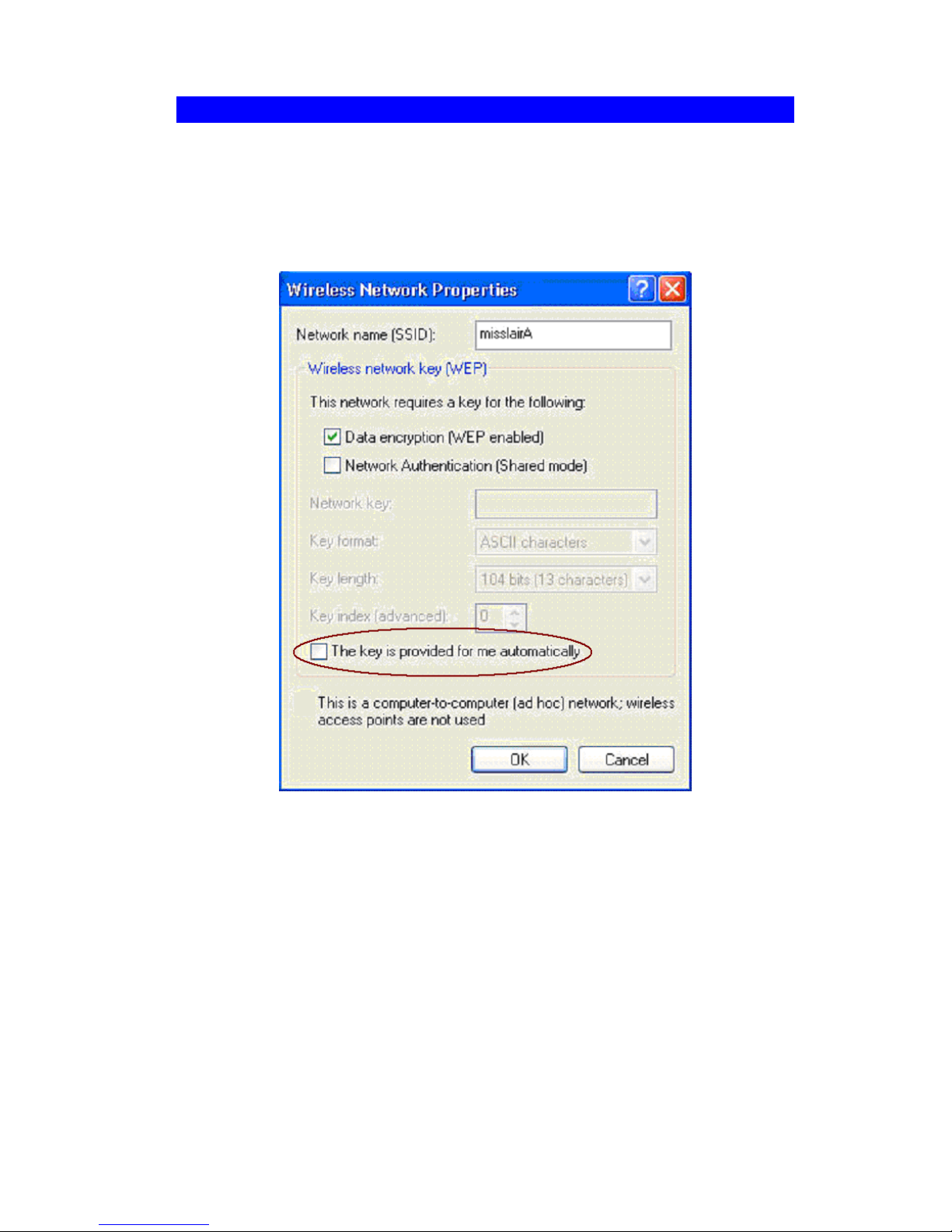
For example, to use EAP-TLS, you would enable Data encryption, and click the
checkbox for the setting The key is provided for me automatically, as shown below.
Page 61
PC and Server Configuration
57
Figure 50: Properties Screen
Setup for Windows XP and 802.1x client is now complete.
Page 62
Wireless Access Point User Guide
58
Using 802.1x Mode (without WPA)
This is very similar to using WPA-Enterprise.
The only difference is that on your client, you must NOT enable the setting The key is
provided for me automatically.
Instead, you must enter the WEP key manually, ensuring it matches the WEP key
used on the Access Point.
Figure 51: Properties Screen
Note:
On some systems, the "64 bit" WEP key is shown as "40 bit" and the "128 bit" WEP
key is shown as "104 bit". This difference arises because the key input by the user is
24 bits less than the key size used for encryption.
Page 63
59
Chapter 5
Operation and Status
This Chapter details the operation of the Wireless Access Point and the
status screens.
Operation
Once both the Wireless Access Point and the PCs are configured, operation is
automatic.
However, you may need to perform the following operations on a regular basis.
If using the Access Control feature, update the Trusted PC database as required.
(See Access Control in Chapter 3 for details.)
If using 802.1x mode, update the User Login data on the Windows 2000 Server,
and configure the client PCs, as required.
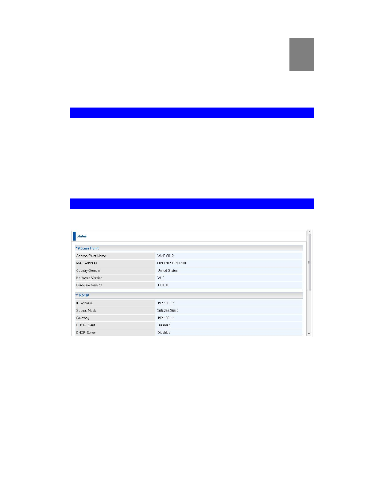
Status Screen
Use the Status link on the main menu to view this screen.
Figure 52: Status Screen
5
Page 64

Wireless Access Point User Guide
60
Data - Status Screen
Access Point
Access Point Name
The current name will be displayed.
MAC Address
The MAC (physical) address of the Wireless Access Point.
Country/Domain
The region or domain, as selected on the System screen.
Hardware Version
The version of the hardware currently used.
Firmware Version
The version of the firmware currently installed.
TCP/IP
IP Address
The IP Address of the Wireless Access Point.
Subnet Mask
The Network Mask (Subnet Mask) for the IP Address
above.
Gateway
Enter the Gateway for the LAN segment to which the Wireless Access Point is attached (the same value as the PCs
on that LAN segment).
DHCP Client
This indicates whether the current IP address was obtained
from a DHCP Server on your network.
It will display "Enabled" or "Disabled".
DHCP Server
"Enabled" or "Disabled" is displayed for the DHCP server
status.
Ethernet Status
The current Ethernet status is displayed.
Wireless
Channel/Frequency
The Channel currently in use is displayed.
Wireless Mode
The current mode (e.g. 802.11g) is displayed.
AP Mode
The current Access Point mode is displayed.
Buttons
Virtual AP Status
Click this to open a sub-window displaying Virtual AP Status
about the information of Name, SSID, Broadcast SSID,
Security, Status and Clients.
Statistics
Click this to open a sub-window where you can view Statistics on data transmitted or received by the Access Point.
Log
Click this to open a sub-window where you can view the
activity log.
Stations
Click this to open a sub-window where you can view the list
of all current Wireless Stations using the Access Point.
Page 65
Operation and Status
61
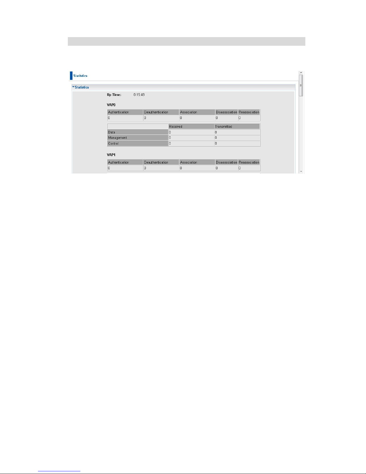
Statistics Screen
This screen is displayed when the Statistics button on the Status screen is clicked. It
shows details of the traffic flowing through the Wireless Access Point.
Figure 53: Statistics Screen
Page 66

Wireless Access Point User Guide
62
Data - Statistics Screen
System Up Time
Up Time
This indicates how long the system has been running since
the last restart or reboot.
VAP
Authentication
The number of "Authentication" packets received. Authentication is the process of identification between the AP and the
client.
Deauthentication
The number of "Deauthentication" packets received. Deauthentication is the process of ending an existing
authentication relationship.
Association
The number of "Association" packets received. Association
creates a connection between the AP and the client. Usually,
clients associate with only one (1) AP at any time.
Disassociation
The number of "Disassociation" packets received. Disassociation breaks the existing connection between the AP and the
client.
Reassociation
The number of "Reassociation" packets received. Reassociation is the service that enables an established association
(between AP and client) to be transferred from one AP to
another (or the same) AP.
Wireless
Data
Number of valid Data packets transmitted to or received from
Wireless Stations, at driver level.
Management
Number of Management packets transmitted to or received
from Wireless Stations.
Control
Number of Control packets transmitted to or received from
Wireless Stations.
Page 67
Operation and Status
63
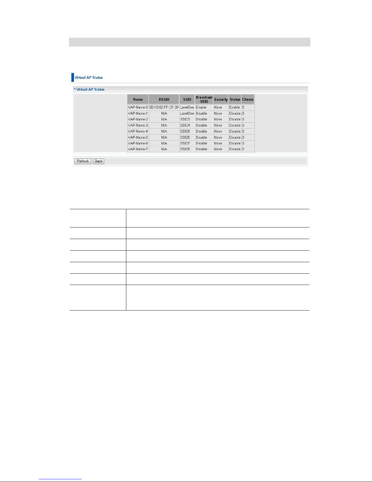
Virtual AP Status
This screen is displayed when the Virtual AP Status button on the Status screen is
clicked.
Figure 54: Virtual AP Status Screen
For each VAP, the following data is displayed:
Name
The name you gave to this VAP; if you didn't change the name,
the default name is used.
BSSIS
The MAC address of the VAP.
SSID
The SSID assigned to this VAP.
Broadcast SSID
Indicates whether or not the SSID is broadcast.
Security
The security method used by this VAP.
Status
Indicates whether or not this VAP is enabled or currently used.
Clients
The number of wireless stations currently using accessing this
Access Point using this VAP.
If the VAP is disabled, this will always be zero.
Page 68
Wireless Access Point User Guide
64
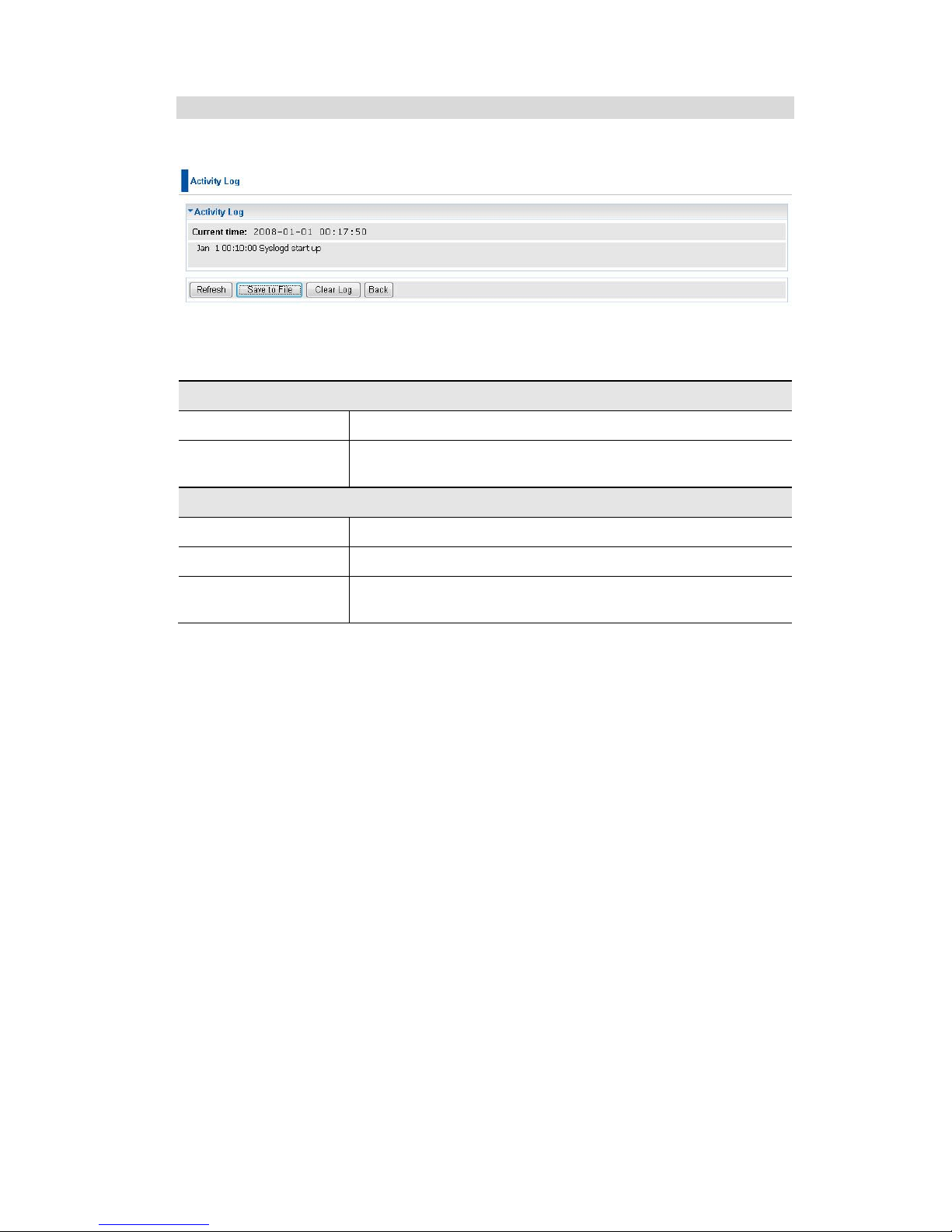
Activity Log
This screen is displayed when the Log button on the Status screen is clicked.
Figure 55: Activity Log Screen
Data - Activity Log
Data
Current Time
The system date and time is displayed.
Log
The Log shows details of the connections to the Wireless
Access Point.
Buttons
Refresh
Update the data on screen.
Save to File
Save the log to a file on your pc.
Clear Log
This will delete all data currently in the Log. This will make it
easier to read new messages.
Page 69
Operation and Status
65
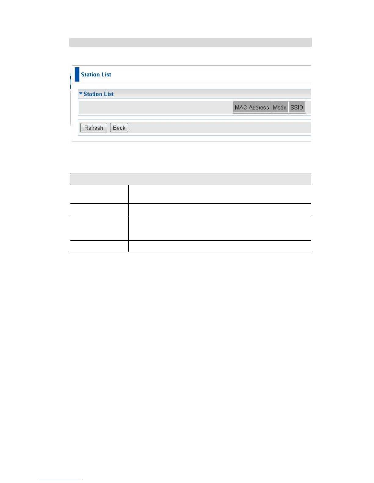
Station List
This screen is displayed when the Stations button on the Status screen is clicked.
Figure 56 Station List Screen
Data - Station List Screen
Station List
MAC Address
The MAC (physical) address of each Wireless Station is
displayed.
Mode
The mode of each Wireless Station.
SSID
This displays the SSID used the Wireless station. Because the
Wireless Access Point supports multiple SSIDs, different PCs
could connect using different SSIDs.
Refresh Button
Update the data on screen.
Page 70
66
Chapter 6
Access Point Management
This Chapter explains when and how to use the Wireless Access
Point's "Management" Features.
Overview
This Chapter covers the following features, available on the Wireless Access Point’s
Management menu.
Admin Login
Auto Config/Update
Config File
SNMP Settings
Log Settings
Upgrade Firmware
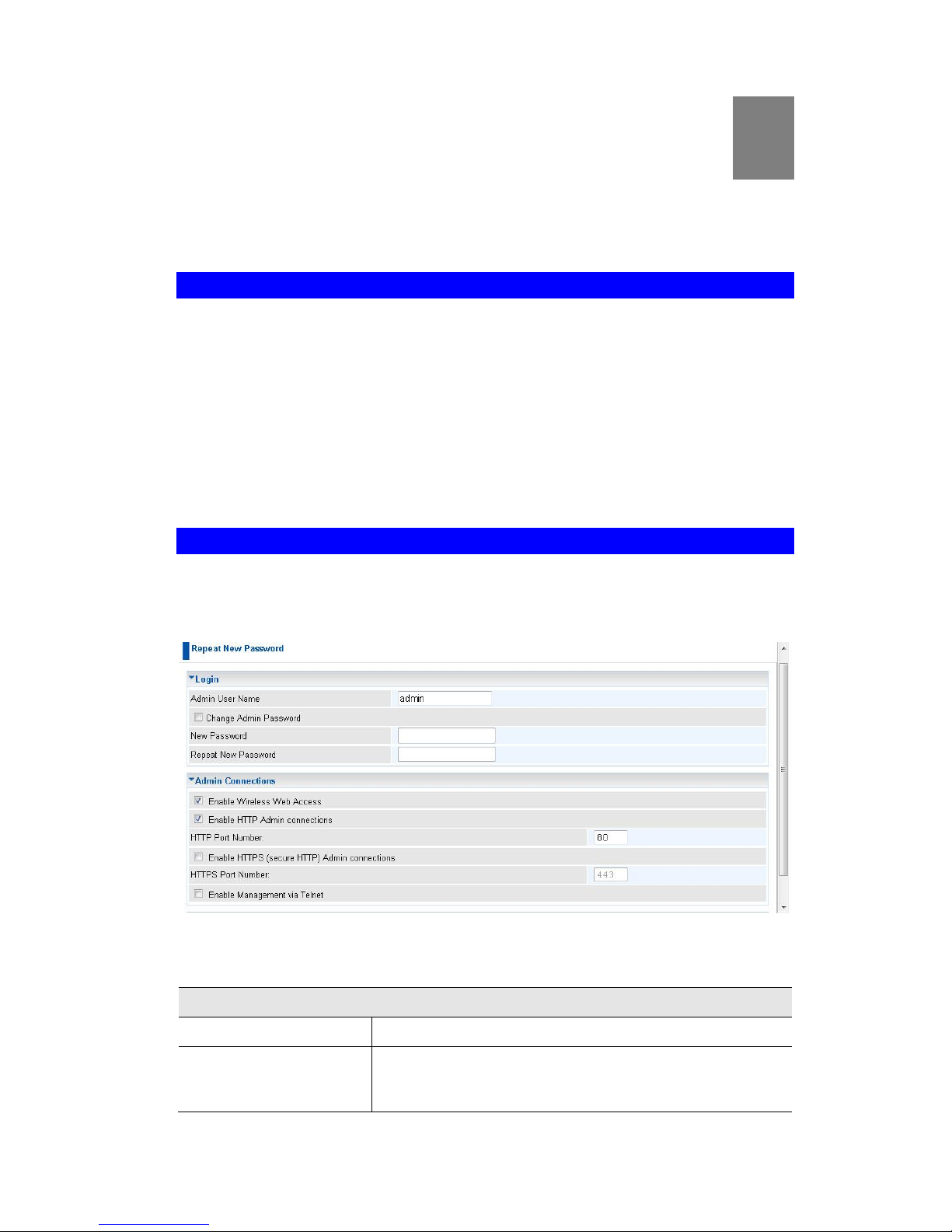
Admin Login Screen
The Admin Login screen allows you to assign a password to the Wireless Access Point.
This password limits access to the configuration interface. The default password is
password. It is recommended that this be changed, using this screen.
Figure 57: Admin Login Screen
Data - Admin Login Screen
Login
Admin User Name
Enter the login name for the Administrator.
Change Admin Password
If you wish to change the Admin password, check this
field and enter the new login password in the fields
below.
6
Page 71

Access Point Management
67
New Password
Enter the desired login password.
Repeat New Password
Re-enter the desired login password.
Admin Connections
Enable Wireless Web
Access
Enable this to allow wireless client access the device.
Enable HTTP
Enable this to allow admin connections via HTTP. If
enabled, you must provide a port number in the field
below. Either HTTP or HTTPS must be enabled.
HTTP Port Number
Enter the port number to be used for HTTP connections
to this device. The default value is 80.
Enable HTTPS
Enable this to allow admin connections via HTTPS
(secure HTTP). If enabled, you must provide a port
number in the field below. Either HTTP or HTTPS must
be enabled.
HTTPS Port Number
Enter the port number to be used for HTTPS connections to this device. The default value is 443.
Enable Management
via Telnet
If desired, you can enable this option. If enabled, you will
able to connect to this AP using a Telnet client. You will
have to provide the same login data (user name, password) as for a HTTP (Web) connection.
Page 72
Wireless Access Point User Guide
68
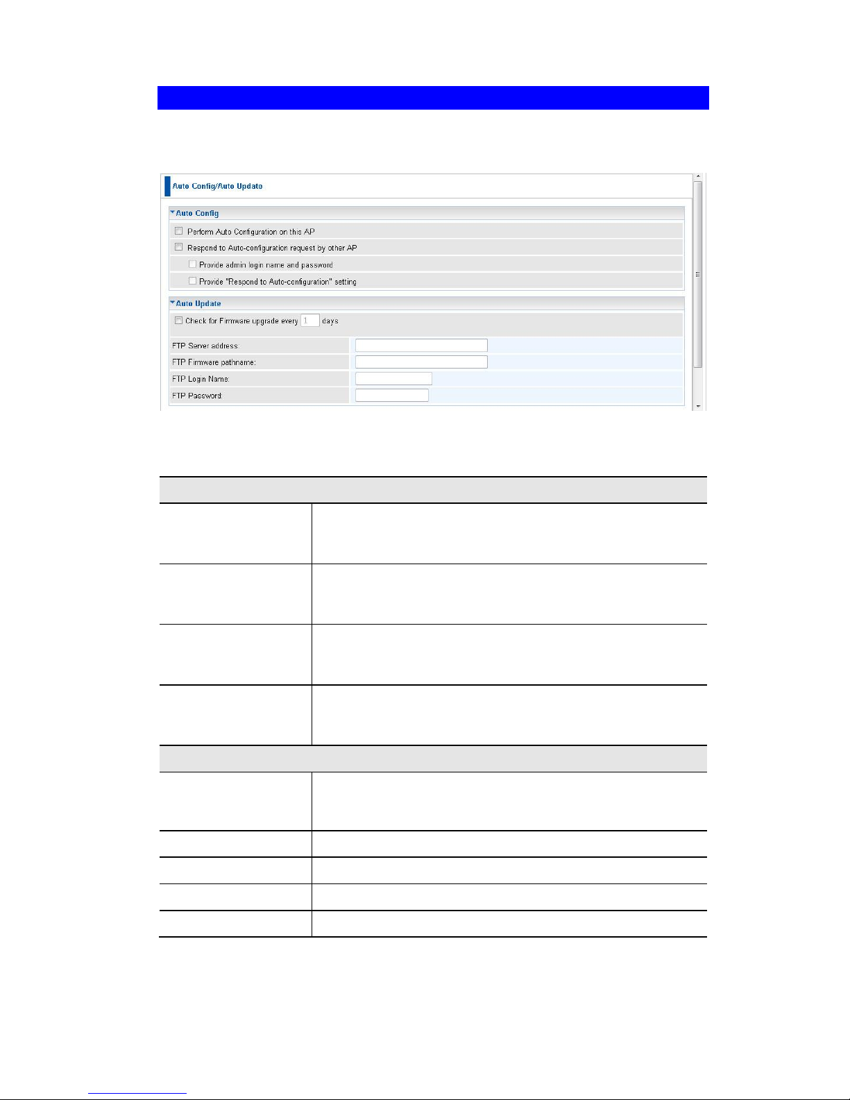
Auto Config/Update
To reach this screen, select Auto Config/Update in the Management section of the
menu.
Figure 58: Auto Config/Auto Update Screen
Data - Auto Config/Auto Update Screen
Auto Config
Perform Auto Configuration on this
AP
If checked, this AP will perform Auto Configuration.
Respond to Autoconfiguration request by other AP
If checked, this AP will respond to other AP’s "Auto Configuration" requests. Otherwise, "Auto Configuration" requests
from other AP will be ignored.
Provide admin login
name and password
If enabled, the login name and password need to be provided.
Provide Respond to
Auto-Configuration
setting
If enabled, the "Respond to Auto-configuration" setting need
to be provided.
Auto Update
Check for Firmware
Upgrade..
If enabled, the device will check the firmware upgrade in the
time interval. Enter the desired day value in the following
field.
FTP Server address
Enter the address for the FTP server.
FTP File pathname
Enter the full path of the firmware in the FTP server.
FTP Login Name
Enter the login name for the FTP server.
FTP Password
Enter the login password for the FTP server.
Page 73
Access Point Management
69
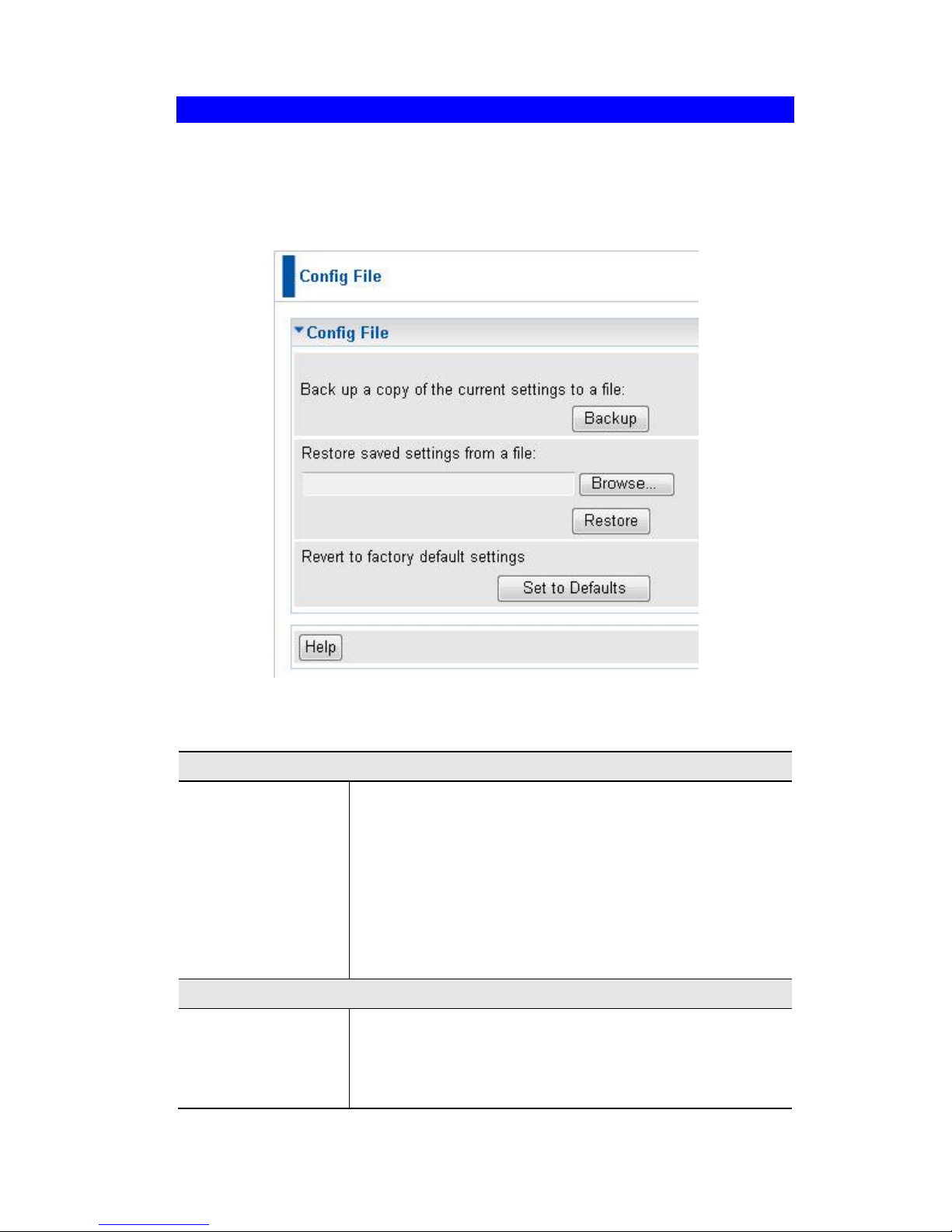
Config File
This screen allows you to Backup (download) the configuration file, and to restore
(upload) a previously-saved configuration file.
You can also set the Wireless Access Point back to its factory default settings.
To reach this screen, select Config File in the Management section of the menu.
Figure 59: Config File Screen
Data - Config File Screen
Backup
Save a copy of
current settings to
a file
Once you have the Access Point working properly, you
should back up the settings to a file on your computer. You
can later restore the Access Point's settings from this file, if
necessary.
To create a backup file of the current settings:
Click Backup.
If you don't have your browser set up to save down-
loaded files automatically, locate where you want to
save the file, rename it if you like, and click Save.
Restore
Restore saved
settings from a file
To restore settings from a backup file:
1. Click Browse.
2. Locate and select the previously saved backup file.
3. Click Restore
Page 74

Wireless Access Point User Guide
70
Defaults
Revert to factory
default settings
To erase the current settings and restore the original factory
default settings, click Set to Defaults button.
Note!
This will terminate the current connection. The Access
Point will be unavailable until it has restarted.
By default, the Access Point will act as a DHCP client,
and automatically obtain an IP address. You will need to
determine its new IP address in order to re-connect.
Page 75
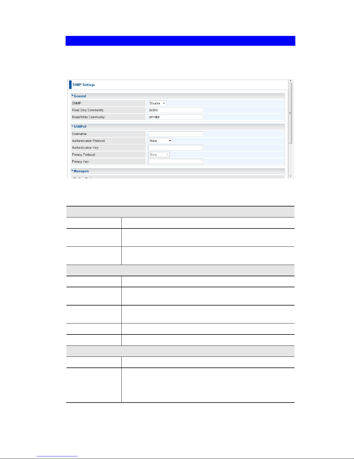
Access Point Management
71
SNMP
SNMP (Simple Network Management Protocol) is only useful if you have a SNMP
program on your PC. To reach this screen, select SNMP in the Management section
of the menu.
Figure 60: SNMP Screen
Data - SNMP Screen
General
SNMP
Use this to enable or disable SNMP as required
Read Only community
Data can be read, but not changed.
Read/Write
Community
Data can be read, and setting changed.
SNMPv3
User Name
Enter the user name for SNMPv3.
Authentication
Protocol
Select the authentication protocol used by SNMPv3.
Authentication
Key
Enter the authentication key required by SNMPv3.
Private Protocol
Select the private protocol as required.
Private Key
Enter the private key here.
Managers
Any Station
The IP address of the manager station is not checked.
Only this station
The IP address is checked, and must match the address you
enter in the IP address field provided.
If selected, you must enter the IP address of the required
station.
Page 76

Wireless Access Point User Guide
72
Traps
Version
Select the desired option, as supported by your SNMP Management program.
Receiver
Select this to have Trap messages sent to the specified PC
only. You must enter the IP Address of the desired PC.
Page 77
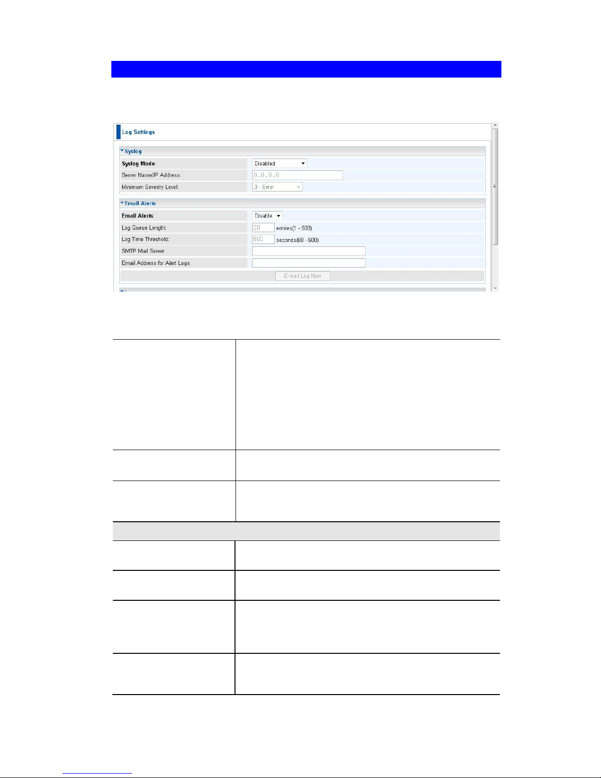
Access Point Management
73
Log Settings
If you have a Syslog Server on your LAN, this screen allows you to configure the
Access Point to send log data to your Syslog Server.
Figure 61: Syslog Settings Screen
Data - Syslog Settings Screen
Syslog Server
Select the desired Option:
Disable - Syslog server is not used.
Broadcast - Syslog data is broadcast. Use this
option if different PCs act as the Syslog server at different times.
Unicast - Select this if the same PC is always used
as the Syslog server. If selected, you must enter the
server address in the field provided.
Server Name/IP Address
Enter the name or IP address of your Syslog Server.
Minimum Severity
Level
Select the desired severity level. Events with a severtiy
level equal to or higher (i.e. lower number) than the
selected level will be logged.
Email Alerts
Email Alerts
If enabled, an e-mail will be sent. If enabled, the e-mail
address information (below) must be provided.
Log Queue Length
Enter the desired length of the log queue. The default is
20 entries.
Log Time Threshold
Enter the preferred value between 60 and 600, which
determine how often the log will be emailed to you.
Normally, this can be left at the default value. The default
is 600 seconds.
SMTP Mail Server
Enter the domain name or IP address of the SMTP
(Simple Mail Transport Protocol) server you use for
sending e-mails.
Page 78

Wireless Access Point User Guide
74
Email Address for
Alert Logs
Enter the e-mail address the log is to be sent to.
E-mail Log Now
Press this button to let the log to be e-mailed immediately.
Log
Email Alerts
Use these checkboxes to determine which events are
included in the log. Checking all options will increase the
size of the log, so it is good practice to disable any
events which are not really required.
Unauthorized Login Attempt - If checked, the
unauthorized users who attempted to login to the
Access Point are logged.
Authorized Login - If checked, this will log the
authorized login TO this Access Point.
System Error Message - If checked, the system
error message will be logged.
Configuration Changes - If checked, the changes
of configuration will be logged.
Page 79
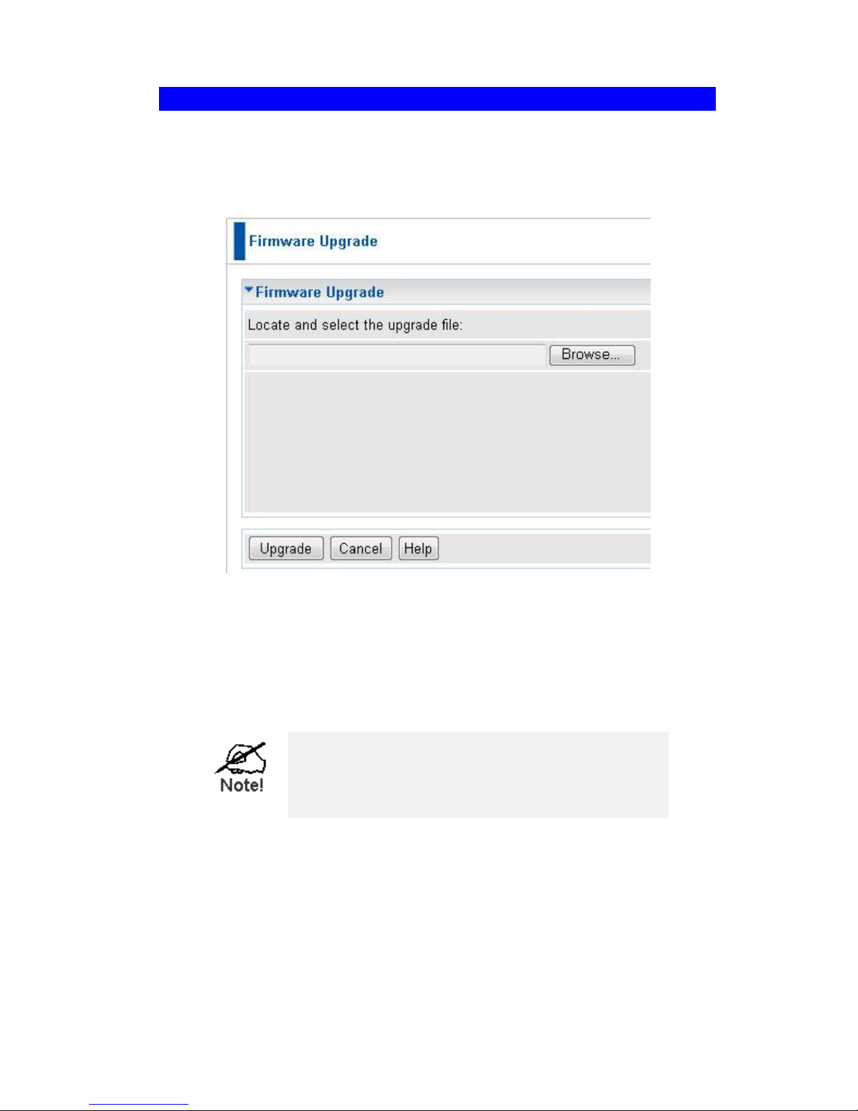
Access Point Management
75
Firmware Upgrade
The firmware (software) in the Wireless Access Point can be upgraded using your
Web Browser.
You must first download the upgrade file, and then select Upgrade Firmware in the
Management section of the menu. You will see a screen like the following.
Figure 62: Firmware Upgrade Screen
To perform the Firmware Upgrade:
1. Click the Browse button and navigate to the location of the upgrade file.
2. Select the upgrade file. Its name will appear in the Upgrade File field.
3. Click the Upgrade button to commence the firmware upgrade.
The Wireless Access Point is unavailable during the
upgrade process, and must restart when the upgrade
is completed. Any connections to or through the
Wireless Access Point will be lost.
Page 80

76
Appendix A
Specifications
Wireless Access Point
Hardware Specifications
CPU
Atheros AR9132
Radio-on-Chip
Atheros AR9103
DRAM
32 Mbytes (can be expanded to 64 Mbytes)
Flash ROM
8 Mbytes
LAN port
1 x Auto-MDIX RJ 45 for 10/100Mbps PoE port
IEEE 802.3af compliance
11b
Embedded Atheros solution
Network Standard IEEE 802.11b (Wi-Fi™) and
IEEE 802.11g compliance
OFDM; 802.11b: CCK (11 Mbps, 5.5 Mbps),
DQPSK (2 Mbps), DBPSK (1 Mbps)
Operating Frequencies 2.412.2.497 GHz
Operating Channels 802.11g: 11 for North America,
13 for Europe (ETSI), 14 for Japan
802.11b: 11 for North America, 14 for Japan, 13 for
Europe (ETSI)
11n
IEEE802.11n compliant
Rx Sensitivity: 11.n: 300Mbps@ -69dBm, 11.g:
54Mbps@ -73dBm, 11.b: 11Mbps@ -88dBm
Antennae
3 x 2dbi detachable antenna
Operating temperature
0 C to 40 C
Storage temperature
-20 C to 70 C
Power Adapter
12VDC 1A External
Dimensions
165mm(W) * 153mm(D) * 33mm(H)
A
Page 81

Appendix A - Specifications
77
Software Specifications
Feature
Details
Wireless
Access point support
Roaming supported
IEEE 802.11n/11g/11b compliance
Auto Sensing Open System / Share Key authentication
Wireless Channels Support
Automatic Wireless Channel Selection
Country Selection
Preamble Type: long or short support
RTS Threshold Adjustment
Fragmentation Threshold Adjustment
Beacon Interval Adjustment
8x Multi-BSSID assignment
802.11i pre-authentication
Short Slot time support
IEEE 802.11d
CTS-only & CTS/RTS protect mechanism support
WMM support
WPS support
Wireless isolations
Operation Mode
Common AP+PTMP/PTP
Universal Repeater
Universal Client
Rogue AP Detection
Security
Open, shared, WPA, WPA-PSK, and WPA2-PSK authenti-
cation
64bit/128bit WEP, TKIP, AES-CCMP support
802.1x support
EAP-MD5, EAP-TLS, EAP-TTLS, PEAP
RADIUS based MAC authentication
Block inter-wireless station communication (wireless sepa-
ration)
Block SSID broadcast
Management
Web based configuration
Configurable Web port
RADIUS Accounting
RADIUS-On feature
RADIUS Accounting update
Telnet/CLI
Syslog/internal Log
Access Control list
Page 82

Wireless Access Point User Guide
78
Editable Configuration file backup/Restore
Statistics support
SNMP v1 & v2c & v3
LLTD
Only wired users to be able to control
Auto configuration
Other Features
DHCP client
WINS client
Radius client
Enable/Disable wireless
Network Intergrality Check
FTP client
Firmware Upgrade
HTTP/FTP network protocol download
Page 83

Appendix A - Specifications
79
FCC Statement
This equipment has been tested and found to comply with the limits for a Class B
digital device, pursuant to Part 15 of the FCC Rules. These limits are designed to
provide reasonable protection against harmful interference in a residential installation.
This equipment generates, uses and can radiate radio frequency energy and, if not
installed and used in accordance with the instructions, may cause harmful interference
to radio communications. However, there is no guarantee that interference will not
occur in a particular installation. If this equipment does cause harmful interference to
radio or television reception, which can be determined by turning the equipment off
and on, the user is encouraged to try to correct the interference by one of the following
measures:
Reorient or relocate the receiving antenna.
Increase the separation between the equipment and receiver.
Connect the equipment into an outlet on a circuit different from that to which the
receiver is connected.
Consult the dealer or an experienced radio/TV technician for help.
To assure continued compliance, any changes or modifications not expressly ap-
proved by the party responsible for compliance could void the user's authority to
operate this equipment. (Example - use only shielded interface cables when connecting to computer or peripheral devices).
FCC Radiation Exposure Statement
This equipment complies with FCC RF radiation exposure limits set forth for an uncontrolled environment. This equipment should be installed and operated with a minimum
distance of 20 centimeters between the radiator and your body.
This device complies with Part 15 of the FCC Rules. Operation is subject to the following two conditions:
(1) This device may not cause harmful interference, and
(2) this device must accept any interference received, including interference that may
cause undesired operation.
This transmitter must not be co-located or operating in conjunction with any other
antenna or transmitter.
Page 84

80
Appendix B
Troubleshooting
Overview
This chapter covers some common problems that may be encountered while using the
Wireless Access Point and some possible solutions to them. If you follow the suggested steps and the Wireless Access Point still does not function properly, contact
your dealer for further advice.
General Problems
Problem 1:
Can't connect to the Wireless Access Point to configure it.
Solution 1:
Check the following:
The Wireless Access Point is properly installed, LAN connections
are OK, and it is powered ON. Check the LEDs for port status.
Ensure that your PC and the Wireless Access Point are on the
same network segment. (If you don't have a router, this must be
the case.)
If your PC is set to "Obtain an IP Address automatically" (DHCP
client), restart it.
You can use the following method to determine the IP address of
the Wireless Access Point, and then try to connect using the IP
address, instead of the name.
To Find the Access Point's IP Address
1. Open a MS-DOS Prompt or Command Prompt Window.
2. Use the Ping command to “ping” the Wireless Access Point.
Enter ping followed by the Default Name of the Wireless Access
Point.
e.g.
ping SC003318
3. Check the output of the ping command to determine the IP address of the Wireless Access Point, as shown below.
Figure 63: Ping
If your PC uses a Fixed (Static) IP address, ensure that it is using an
IP Address which is compatible with the Wireless Access Point. (If no
DHCP Server is found, the Wireless Access Point will default to an IP
Address and Mask of 192.168.0.228 and 255.255.255.0.) On Windows PCs, you can use Control Panel-Network to check the
B
Page 85

Appendix B - Troubleshooting
81
Properties for the TCP/IP protocol.
Problem 2:
My PC can't connect to the LAN via the Wireless Access Point.
Solution 2
Check the following:
The SSID and WEP settings on the PC match the settings on the
Wireless Access Point.
On the PC, the wireless mode is set to "Infrastructure"
If using the Access Control feature, the PC's name and address
is in the Trusted Stations list.
If using 802.1x mode, ensure the PC's 802.1x software is confi-
gured correctly. See Chapter 4 for details of setup for the
Windows XP 802.1x client. If using a different client, refer to the
vendor's documentation.
Page 86
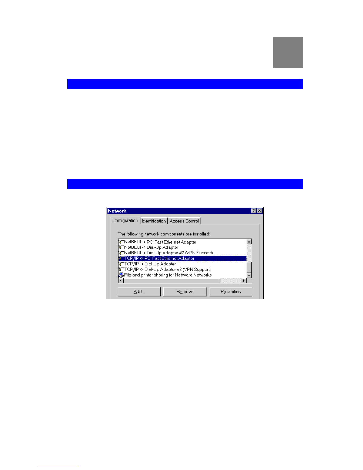
82
Appendix C
Windows TCP/IP
Overview
Normally, no changes need to be made.
By default, the Wireless Access Point will act as a DHCP client, automatically
obtaining a suitable IP Address (and related information) from your DHCP Server.
If using Fixed (specified) IP addresses on your LAN (instead of a DHCP Server),
there is no need to change the TCP/IP of each PC. Just configure the Wireless
Access Point to match your existing LAN.
The following sections provide details about checking the TCP/IP settings for various
types of Windows, should that be necessary.
Checking TCP/IP Settings - Windows 9x/ME:
1. Select Control Panel - Network. You should see a screen like the following:
Figure 64: Network Configuration
2. Select the TCP/IP protocol for your network card.
3. Click on the Properties button. You should then see a screen like the following.
C
Page 87
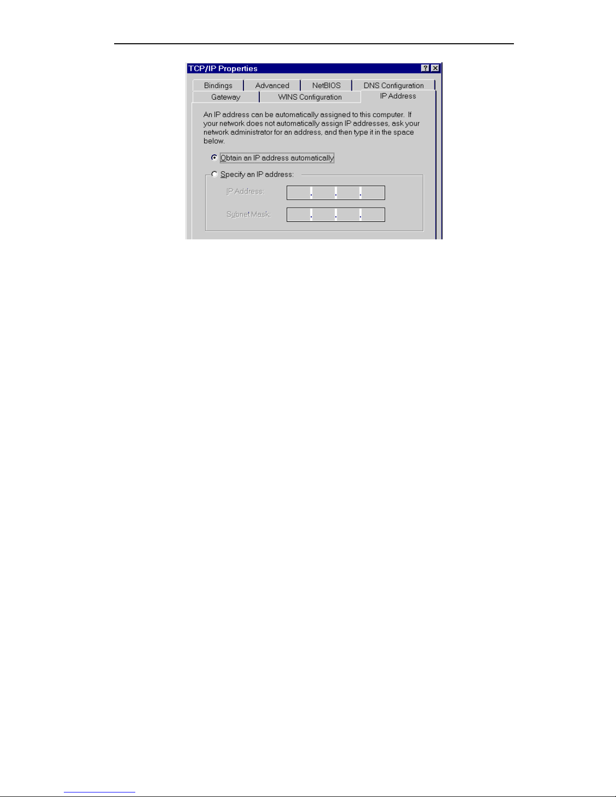
Appendix C - Windows TCP/IP
83
Figure 65: IP Address (Win 95)
Ensure your TCP/IP settings are correct, as follows:
Using DHCP
To use DHCP, select the radio button Obtain an IP Address automatically. This is the
default Windows settings. To work correctly, you need a DHCP server on your LAN.
Using "Specify an IP Address"
If your PC is already configured for a fixed (specified) IP address, no changes are
required.
(The Administrator should configure the Wireless Access Point with a fixed IP address
from the same address range used on the PCs.)
Page 88
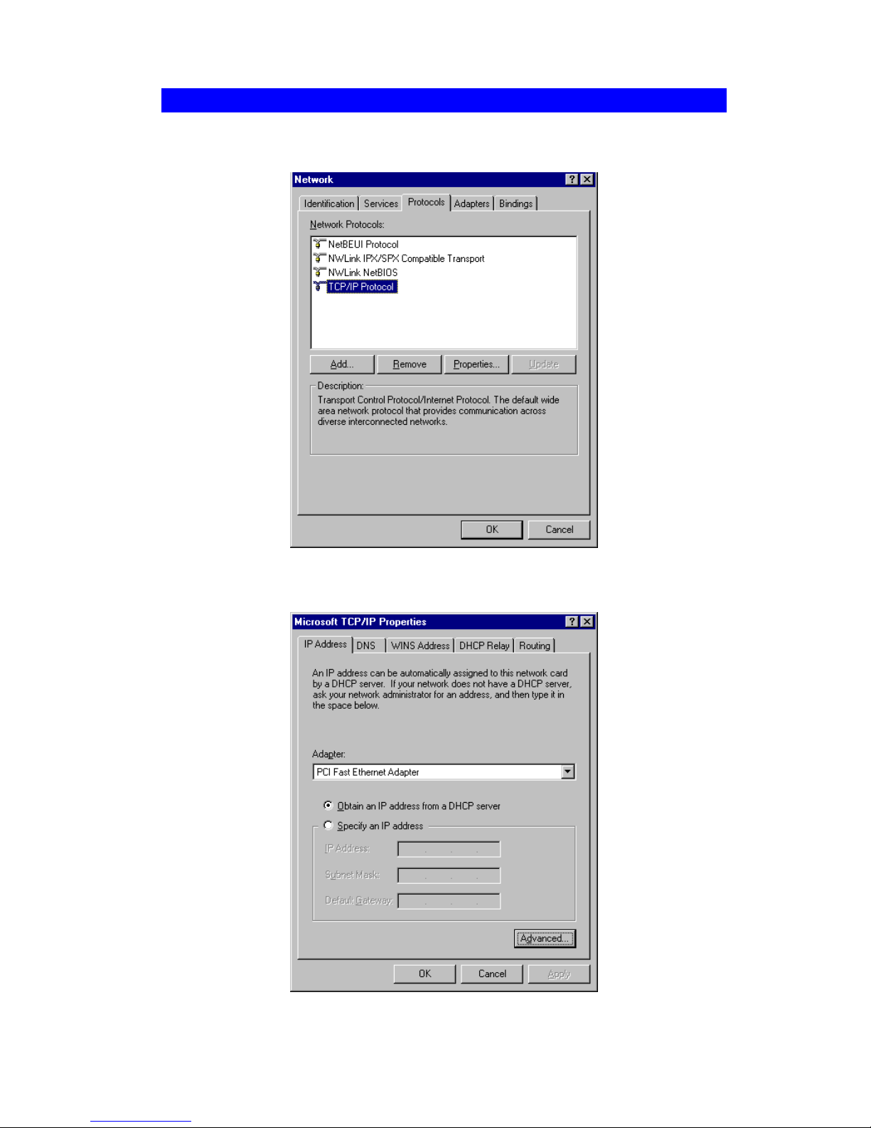
Wireless Access Point User Guide
84
Checking TCP/IP Settings - Windows NT4.0
1. Select Control Panel - Network, and, on the Protocols tab, select the TCP/IP
protocol, as shown below.
Figure 66: Windows NT4.0 - TCP/IP
2. Click the Properties button to see a screen like the one below.
Figure 67: Windows NT4.0 - IP Address
3. Select the network card for your LAN.
Page 89

Appendix C - Windows TCP/IP
85
4. Select the appropriate radio button - Obtain an IP address from a DHCP Server or
Specify an IP Address, as explained below.
Obtain an IP address from a DHCP Server
This is the default Windows setting. This is the default Windows settings. To work
correctly, you need a DHCP server on your LAN.
Using "Specify an IP Address"
If your PC is already configured for a fixed (specified) IP address, no changes are
required.
(The Administrator should configure the Wireless Access Point with a fixed IP address
from the same address range used on the PCs.)
Page 90
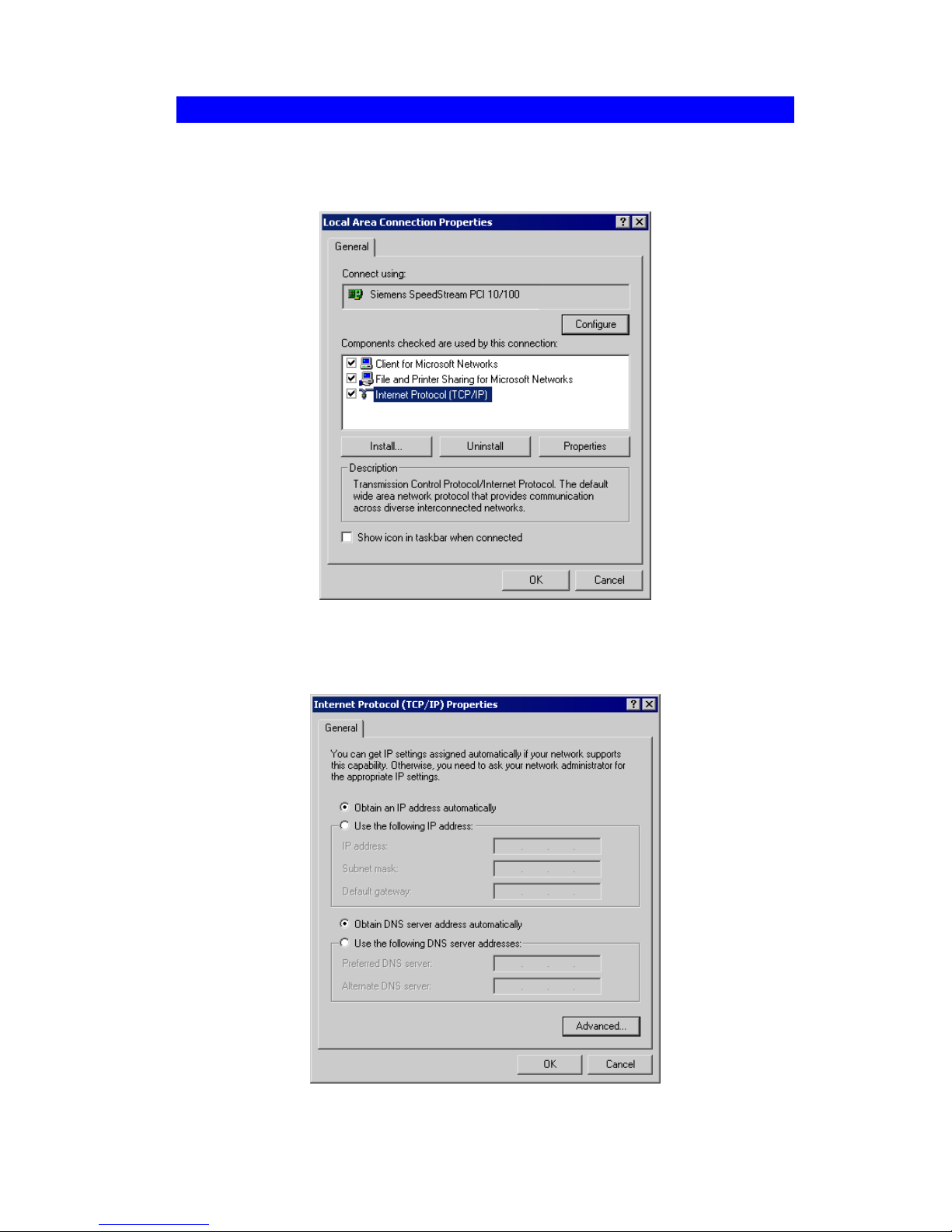
Wireless Access Point User Guide
86
Checking TCP/IP Settings - Windows 2000
5. Select Control Panel - Network and Dial-up Connection.
6. Right click the Local Area Connection icon and select Properties. You should see
a screen like the following:
Figure 68: Network Configuration (Win 2000)
7. Select the TCP/IP protocol for your network card.
8. Click on the Properties button. You should then see a screen like the following.
Figure 69: TCP/IP Properties (Win 2000)
Page 91

Appendix C - Windows TCP/IP
87
9. Ensure your TCP/IP settings are correct:
Using DHCP
To use DHCP, select the radio button Obtain an IP Address automatically. This is the
default Windows setting. This is the default Windows settings. To work correctly, you
need a DHCP server on your LAN.
Using a fixed IP Address ("Use the following IP Address")
If your PC is already configured for a fixed (specified) IP address, no changes are
required.
(The Administrator should configure the Wireless Access Point with a fixed IP address
from the same address range used on the PCs.)
Page 92
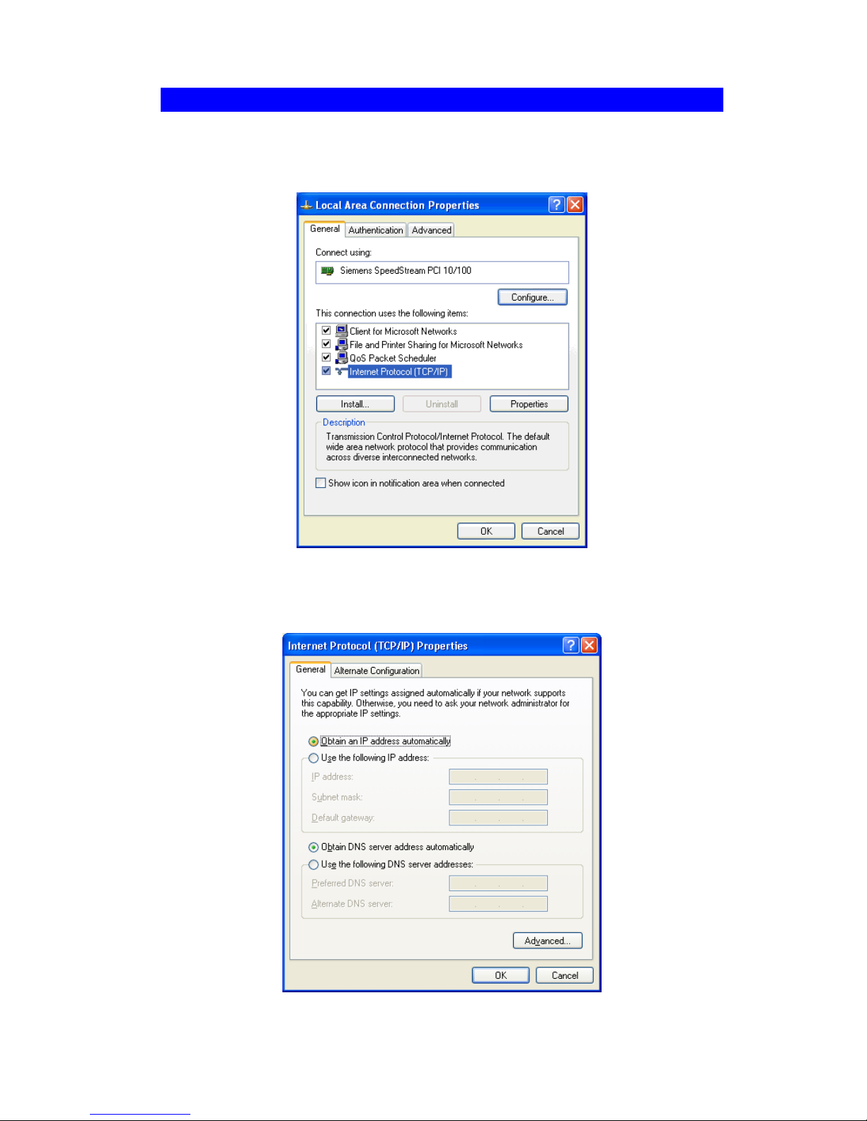
Wireless Access Point User Guide
88
Checking TCP/IP Settings - Windows XP
1. Select Control Panel - Network Connection.
2. Right click the Local Area Connection and choose Properties. You should see a
screen like the following:
Figure 70: Network Configuration (Windows XP)
3. Select the TCP/IP protocol for your network card.
4. Click on the Properties button. You should then see a screen like the following.
Figure 71: TCP/IP Properties (Windows XP)
Page 93

Appendix C - Windows TCP/IP
89
5. Ensure your TCP/IP settings are correct.
Using DHCP
To use DHCP, select the radio button Obtain an IP Address automatically. This is the
default Windows setting. To work correctly, you need a DHCP server on your LAN.
Using a fixed IP Address ("Use the following IP Address")
If your PC is already configured for a fixed (specified) IP address, no changes are
required.
(The Administrator should configure the Wireless Access Point with a fixed IP address
from the same address range used on the PCs.)
Page 94
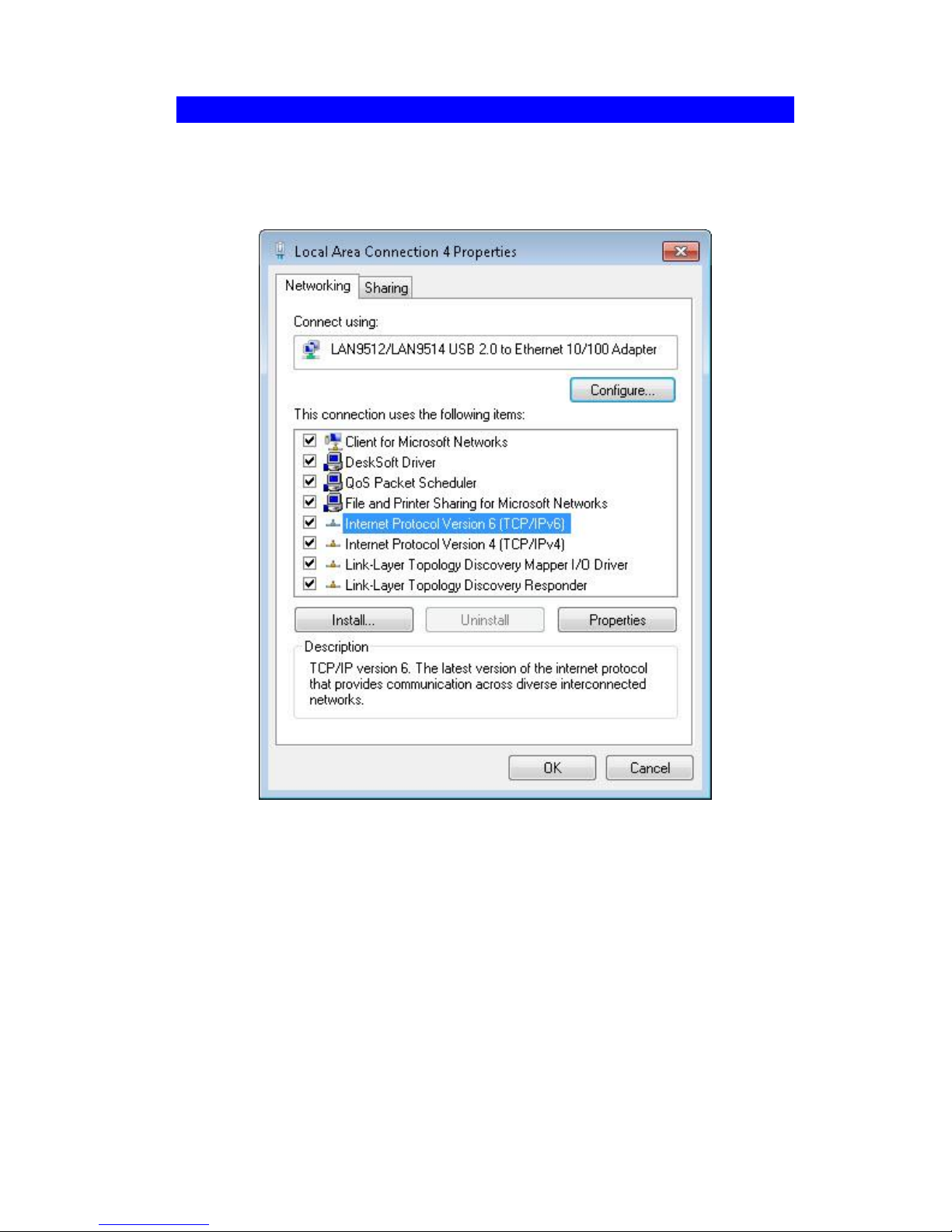
Wireless Access Point User Guide
90
Checking TCP/IP Settings - Windows Vista / 7
1. Select Control Panel - Network Connections.
2. Right click the Local Area Connection Status and choose Properties. Click Contin-
ue to the User Account Control dialog box, then you should see a screen like the
following:
Figure 72: Network Configuration (Windows Vista)
3. Select the TCP/IP protocol for your network card.
4. Click on the Properties button. You should then see a screen like the following.
Page 95
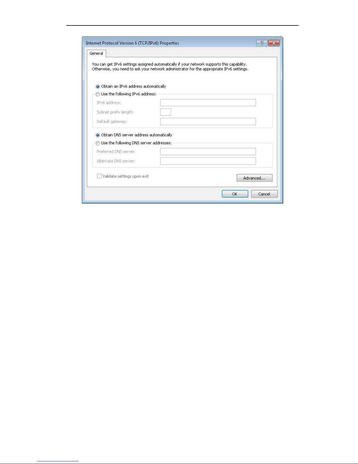
Appendix C - Windows TCP/IP
91
Figure 73: TCP/IP Properties (Windows Vista)
5. Ensure your TCP/IP settings are correct.
Using DHCP
To use DHCP, select the radio button Obtain an IP Address automatically. This is the
default Windows setting. To work correctly, you need a DHCP server on your LAN.
Using a fixed IP Address ("Use the following IP Address")
If your PC is already configured for a fixed (specified) IP address, no changes are
required.
(The Administrator should configure the Wireless Access Point with a fixed IP address
from the same address range used on the PCs.)
Page 96

92
Appendix D
About Wireless LANs
Overview
Wireless networks have their own terms and jargon. It is necessary to understand
many of these terms in order to configure and operate a Wireless LAN.
Wireless LAN Terminology
Modes
Wireless LANs can work in either of two (2) modes:
Ad-hoc
Infrastructure
Ad-hoc Mode
Ad-hoc mode does not require an Access Point or a wired (Ethernet) LAN. Wireless Stations (e.g. notebook PCs with wireless cards) communicate directly with
each other.
Infrastructure Mode
In Infrastructure Mode, one or more Access Points are used to connect Wireless
Stations (e.g. Notebook PCs with wireless cards) to a wired (Ethernet) LAN. The
Wireless Stations can then access all LAN resources.
Access Points can only function in "Infrastructure" mode,
and can communicate only with Wireless Stations which are
set to "Infrastructure" mode.
SSID/ESSID
BSS/SSID
A group of Wireless Stations and a single Access Point, all using the same ID
(SSID), form a Basic Service Set (BSS).
Using the same SSID is essential. Devices with different SSIDs are unable to
communicate with each other. However, some Access Points allow connections
from Wireless Stations which have their SSID set to “any” or whose SSID is blank
( null ).
ESS/ESSID
A group of Wireless Stations, and multiple Access Points, all using the same ID
(ESSID), form an Extended Service Set (ESS).
D
Page 97

Appendix D - About Wireless LANs
93
Different Access Points within an ESS can use different Channels. To reduce interference, it is recommended that adjacent Access Points SHOULD use different
channels.
As Wireless Stations are physically moved through the area covered by an ESS,
they will automatically change to the Access Point which has the least interference
or best performance. This capability is called Roaming. (Access Points do not
have or require Roaming capabilities.)
Channels
The Wireless Channel sets the radio frequency used for communication.
Access Points use a fixed Channel. You can select the Channel used. This allows
you to choose a Channel which provides the least interference and best performance. For 802.11g, 13 channels are available in the USA and Canada., but
11channels are available in North America if using 802.11b.
If using multiple Access Points, it is better if adjacent Access Points use different
Channels to reduce interference. The recommended Channel spacing between
adjacent Access Points is 5 Channels (e.g. use Channels 1 and 6, or 6 and 11).
In "Infrastructure" mode, Wireless Stations normally scan all Channels, looking for
an Access Point. If more than one Access Point can be used, the one with the
strongest signal is used. (This can only happen within an ESS.)
If using "Ad-hoc" mode (no Access Point), all Wireless stations should be set to
use the same Channel. However, most Wireless stations will still scan all Channels to see if there is an existing "Ad-hoc" group they can join.
WEP
WEP (Wired Equivalent Privacy) is a standard for encrypting data before it is transmitted. This is desirable because it is impossible to prevent snoopers from receiving any
data which is transmitted by your Wireless Stations. But if the data is encrypted, then it
is meaningless unless the receiver can decrypt it.
If WEP is used, the Wireless Stations and the Wireless Access Point must have
the same settings.
WPA-PSK
Like WEP, data is encrypted before transmission. WPA is more secure than WEP, and
should be used if possible. The PSK (Pre-shared Key) must be entered on each Wireless station. The 256Bit encryption key is derived from the PSK, and changes
frequently.
WPA2-PSK
This is a further development of WPA-PSK, and offers even greater security, using the
AES (Advanced Encryption Standard) method of encryption.
WPA-Enterprise
This version of WPA requires a Radius Server on your LAN to provide the client authentication according to the 802.1x standard. Data transmissions are encrypted using
the WPA standard.
Page 98

Wireless Access Point User Guide
94
If this option is used:
The Access Point must have a "client login" on the Radius Server.
Each user must have a "user login" on the Radius Server.
Each user's wireless client must support 802.1x and provide the login data when
required.
All data transmission is encrypted using the WPA standard. Keys are automatically
generated, so no key input is required.
802.1x
This uses the 802.1x standard for client authentication, and WEP for data encryption. If
possible, you should use WPA-Enterprise instead, because WPA encryption is much
stronger than WEP encryption.
If this option is used:
The Access Point must have a "client login" on the Radius Server.
Each user must have a "user login" on the Radius Server.
Each user's wireless client must support 802.1x and provide the login data when
required.
All data transmission is encrypted using the WEP standard. You only have to
select the WEP key size; the WEP key is automatically generated.
Page 99
95
Appendix E
Command Line Interface
Overview
If desired, the Command Line Interface (CLI) can be used for configuration. This
creates the possibility of creating scripts to perform common configuration changes.
The CLI requires a Telnet connection to the Wireless Access Point.
Using the CLI - Telnet
1. Start your Telnet client, and establish a connection to the Access Point.
e.g.
Telnet 192.168.1.1
2. You will be prompted for the user name and password. Enter the same login name
and password as used for the HTTP (Web) interface.
The default values are admin for the User Name, and password for the Password.
3. Once connected, you can use any of the commands listed in the following Com-
mand Reference.
Command Reference
The following commands are available.
config vap
Config Virtual AP X
?
Display CLI Command List
help
Display CLI Command List
get 11nampdu
Set 11n A-MPDU Aggregation Mode
get 11namsdu
Set 11n A-MSDU Aggregation Mode
get 11nguardinterval
Set 11n Guard Interval Mode
get 11nsubchannel
Set 11n Extension Sub-Channel
get 11nradioband
Set 11n Radio Band
get 802.11d
Display 802.11d Mode
get acctserver
Display Accounting Server
get acctport
Display Accounting Port
get acctsecret
Display Accounting Secret
get acl
Display Access Control Status
get active
Display VAP Active (up) Mode
get aging
Display Idle Timeout Interval
get authentication
Display Authentication Type of WEP
get beaconinterval
Display Beacon Interval
E
Page 100

Wireless Access Point User Guide
96
get channel
Display Radio Channel
get country
Display Country/Domain
get defaultkey
Display Default Key Index
get description
Display Access Point Description
get dhcp
Display DHCP Mode
get dhcpserverendip
Display DHCP Server End IP Address
get dhcpserverstartip
Display DHCP Server start IP Address
get dnsserver
Display IP Address of DNS Server
get
dot1xdynkeyupdate
Display 802.1x Dynamic Key Update Mode
get dot1xdynkeylife
Display 802.1x Dynamic Key Life Time (in Minutes)
get dot1xkeytype
Display 802.1x Distribute Key Method
get fragthreshold
Display Fragment Threshold
get gateway
Display Gateway IP Address
get gtkupdate
Display Group Key Update Mode
get gtkupdateinterval
Display Group Key Update Interval (in Seconds)
get http
Display HTTP Mode
get httpport
Display HTTP Port Number
get https
Display HTTPS Mode
get httpsport
Display HTTPS Port Number
get ipaddr
Display IP Address
get ipmask
Display IP Subnet Mask
get isolation
Display Isolate All Virtual APs State
get key
Display WEP Key Value
get keylength
Display WEP Key Length
get lltd
Display LLTD Mode
get md5supplicant
Display 802.1x MD5 Supplicant Mode
get md5suppname
Display 802.1x Supplicant MD5 Name
get md5supppassword
Display 802.1x Supplicant MD5 Password
get md5supptype
Display 802.1x MD5 Supplicant Type
get nativevlanid
Display Native VLAN ID
get ntp
Display NTP Server IP Address
get operationmode
Display Operation Mode
get password
Display Login Password
get psk
Display Pre-shared Key
get radiusserver
Display RADIUS Server IP Address
 Loading...