

LevelOne VOI-9200 User Manual

VOI-9200
SIP IP PBX
User Manual
Ver. 1.00 - 0611

Table of Contents
1. INTRODUCTION.................................................................................................3
1.1. OVERVIEW ..................................................................................................... 3
1.2. FEATURE ....................................................................................................... 4
1.3. PACKAGE CONTENT........................................................................................ 5
1.4. PHYSICAL ...................................................................................................... 5
1.5. DEFAULT SETTINGS ........................................................................................ 7
1.6. CONNECTION DIAGRAM................................................................................... 7
2. WEB BASED MANAGEMENT...........................................................................8
2.1. SYSTEM......................................................................................................... 9
2.2. SERVICE ...................................................................................................... 22
2.3. USER MANAGEMENT..................................................................................... 29
2.4. DEVICE........................................................................................................ 34
2.5. ROUTE MANAGEMENT................................................................................... 42
2.6. TRUNK......................................................................................................... 46
2.7. FEATURE ..................................................................................................... 56
3. APPLICATION EXAMPLES.............................................................................67
3.1. CASE I: SINGLE-SITE IP PBX ........................................................................ 68
3.2. CASE II: TWO-SITE IP PBX........................................................................... 69
4. APPENDIX - SPECIFICATION......................................................................... 72
5. GENERAL PUBLIC LICENSE.......................................................................... 73
1. Introduction
1.1. Overview
The VOI-9200 IP PBX is an embedded Voice over IP (VoIP) Server with Session
Initiation Protocol (SIP) to provide global virtual office IP extension phone connection
for small-to-medium business (SMB) companys. Equipped with two FXS ports,
two FXO ports, Ethernet LAN and WAN ports, VOI-9200 combines the telephony
network and the data network into a manageable converged network.
VOI-9200 IP PBX works with various IP phones (Desktop, WiFi, Bluetooth, and
DECT), VoIP gateways, and analog telephone adapters (ATA) to route calls among
client phones, analog phones, and PSTN network. Call features such as
conferencing, auto attendant, and voicemail can be seamlessly enabled to all phone
devices. In addition, it also provides Internet access to all LAN devices through NAT
router.
VOI-9200 IP PBX provides call control and media relay services to SIP clients, and it
performs the following primary functions:
SIP Registrar
SIP Outbound Proxy with media relay
SIP Gateways (FXO)
SIP PBX for extension calls
Auto attendant Interactive Voice Response (IVR)
Voice Mail IVR
Meet-Me Conferencing
VOI-9200 IP PBX has a built-in suite of voice applications for supplementary services.
This lowers down the total cost of a converged network enabled by VOI-9200 IP PBX
than building separated infrastructures for legacy telephony network and data
network. In addition, with a web-browsable interface to the data network configuration
and voice service provisioning, VOI-9200 brings the manageability of both networks
together to facilitate administration locally or remotely.

1.2. Feature
Supported Standards
RFC 3261, RFC 3311, RFC 3515
RFC 3265, RFC 3892, RFC 3361
RFC 3842, RFC 3389, RFC 3489
RFC 3428, RFC 2327, RFC 2833
RFC 2976, RFC 3263, RFC 3264
SIP Registrar
‧ Static/Dynamic registration
‧ Configurable expiry time
‧ MD5 authentication
‧ Registration proxy to external registrars
‧ Configurable PBX Caller ID
‧ User profile
‧ Handle loose RFC-compliant phones
‧ Resilient message retry mechanism
‧ Seeding historical registrations
SIP Proxy
‧ Proxy server
‧ Call-based MD5 authentication
‧ NAT traversal for clients
‧ Outbound proxy with or without WAN
‧ Inter-proxy call hand-off
PBX Features
‧ Support call hold, call waiting, 3-way call conference
with feature phones
‧ Built-in in-line call transfer
‧ Unconditional, unavailable, busy call forward
‧ Per-calling-number forward and rejection
‧ Group-based call pick-up
‧ Call-parking
‧ Multi-room meet-me conference
‧ Auto-attendant
‧ Voice mail system
‧ Call privilege grouping
‧ FXO interface for PSTN Inbound/outbound
‧ FXO disconnection tone detection
‧ FXO hunt group
‧ Caller ID detection
‧ Echo cancellation
‧ In-band/RFC2833/SIP-INFO DTMF translation
‧ Support 5 SIP trunk
‧ Intra-PBX stackable trunking over Ethernet
‧ FWD/Vonage account sharing for extensions
‧ Interoperable with Cisco
CallManager, CCME, IOS SIP gateway, Unity
CUE, 79XX, ATA
‧ Call admission control for wired/wireless phones
‧ Music on hold
‧ Direct line
‧ Outbound 900/0204 blocking
Auto Attendant
‧ Configurable Greeting
‧ Key to reach operator
‧ Timeout interval and timeout action
‧ Music on ringing extensions
‧ Forward to voice mail on no-answer
Voice Mail
‧ User PIN
‧ Multilingual
‧ Multi-folder archive
‧ Fast-forward/Rewind/Undelete
‧ MWI notification
‧ E-mail notification and attachment(Unified messaging)
‧ Personal reception on unavailability and busy
‧ Voicemail forwarding
‧ Reply call or new call in voicemail menu
Storage
‧ Support USB 2.0 storage media
Meet-me Conference
‧ Multiple rooms with configurable number and PIN
‧ Music on first dial-in party
‧ Hot key to leave conference
NAT
‧ Auto NAT discovery and traversal
‧ Built-in STUN client
‧ RTP proxy
‧ RTP port range designation
Relational Provision
‧ Logical partition/relation on users and trunks
‧ Logical provision on outgoing and incoming
calling search scopes
‧ Rich dial-plan expressiveness through route patterns
‧ Object-oriented provisioning paradigm
Administration
‧ Web-based configuration
‧ Flat system event syslog
‧ Flat Call Detail Record (CDR)
‧ Extension status display
‧ TFTP server and TFTP repository maintenance
‧ Network Time Protocol time synchronization
‧ Real Time Clock setting
‧ DHCP server with multiple partitions,
per-MAC IP binding, list of options
‧ Configurable time zone
‧ Firmware upgrade through Web interface
Network Management
‧ DHCP/PPPoE/Static IP on WAN
‧ LAN IP and netmask specification
‧ Firewalling on predefined services
‧ NAT for outbound traffic from LAN
‧ DNS and dynamic DNS
‧ QoS queuing mechanism for VoIP and data traffic
Maximum Capacity
‧ 30 extension registrations
‧ 30 voicemail accounts
‧ 10 concurrent calls with RTP
‧ 4 analog calls
Voice
‧ Caller ID : Bellcore and ESTI
‧ Fax support: T.38 compliant
‧ Echo canceller: G.168-2002 compliant
‧ Seamless integrated with VOI-7000 / VOI-7100,
VOI-800x

1.3. Package Content
- VOI-9200
- Power Adapter 12V, 3A
- Cat.5 Cable
- CD Manual
- Quick Installation Guide
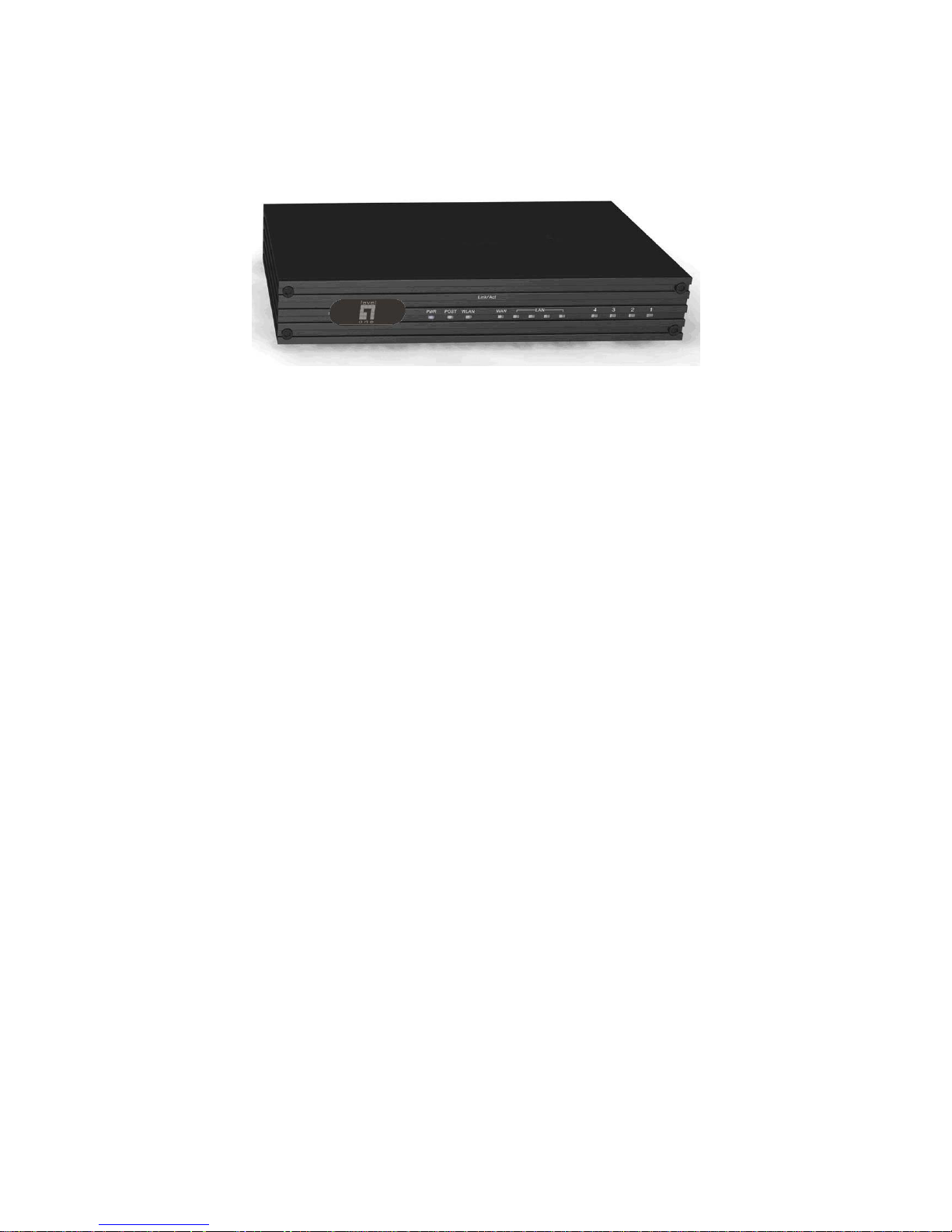
1.4. Physical
1.4.1. Front Panel
LED
1. Line 2-Port FXO
2. Phone 2-Port FXS
3. LAN ON indicates LAN connection
BLINK indicates LAN activity
4. WAN ON indicates WAN connection
BLINK indicates WAN activity
5. WLAN Reserved *
6. Active On Indicates the system is ready
7. PWR ON indicates the unit is powered up
* WLAN is not applicable for the VOI-9200
1 2 34567
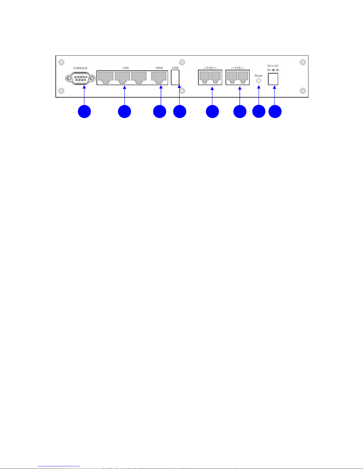
1.4.2. Rear Panel
1. Power 12V DC, 3.0A
2. Reset Hold the Reset button and release to reboot system
Hold the Reset button for 10 seconds before release to
restore whole system back to the factory default
3. FXO ports 2 FXO ports are for connection to PSTN lines, and
numbered 1 and 2 from left to right.
4. FXS ports 2 FXS ports are for connection to the analog phone,
and numbered 3 and 4 from left to right.
5. USB port Connect to an external USB drive for backup internal
system storage. Click the Backup icon in Web
configurations and follow instructions to insert the USB
connector of an external USB drive.
6. WAN port Connect to a broadband ADSL/Cable modem or a
WAN router.
7. LAN ports 4 LAN ports are for connection to PC or Laptop,
extended IP Phones, or VoIP Gateways/ATA, etc.
8. Console port RS-232 Serial connection for configuration by CLI
1
2
34567 8
1.5. Default Settings
WAN IP
192.168.0.1
LAN IP
192.168.1.1
Username
admin
Password
admin
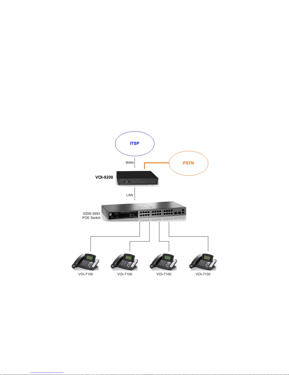
1.6. Connection Diagram
2. Web Based Management
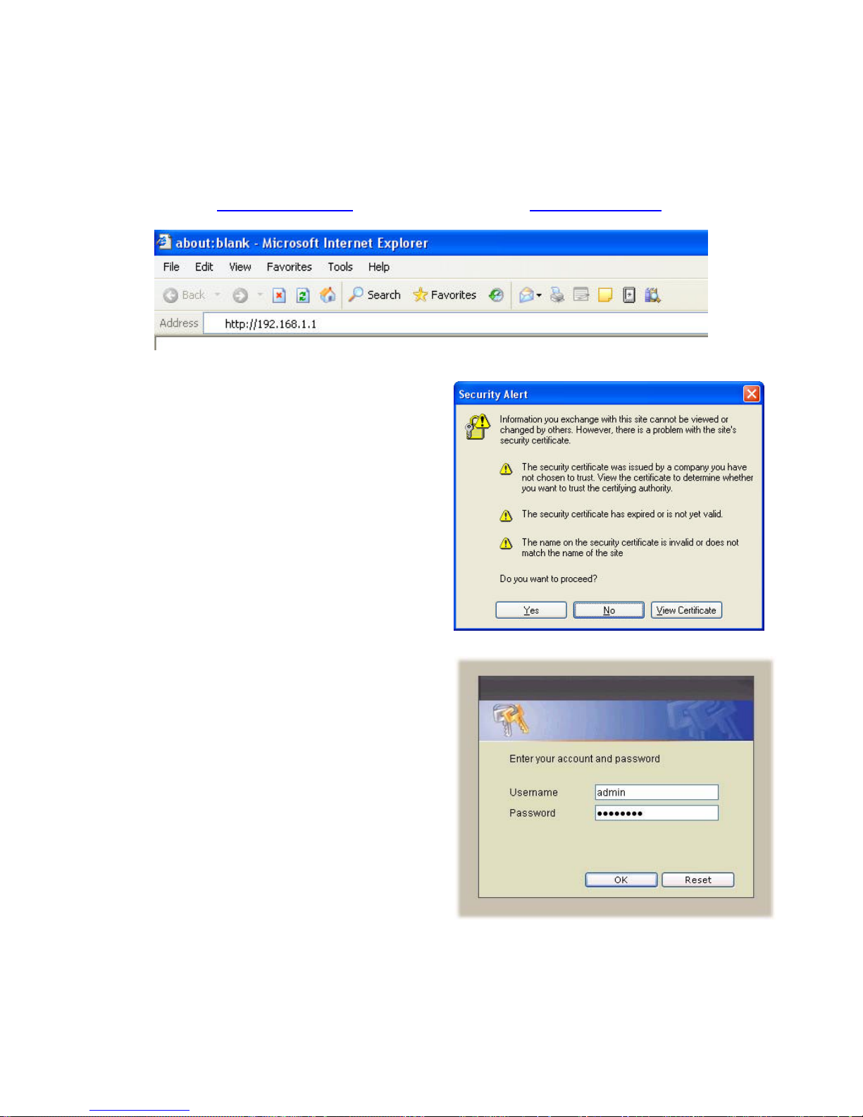
This chapter illustrates how to login and configure system parameters with VOI-9200.
The factory default of LAN IP address is 192.168.1.1 and WAN IP address is
192.168.0.1. You can connect your PC or laptop to access the web GUI through
LAN port at https://192.168.1.1/, or through WAN port at https://192.168.0.1.
Once connected, the browser may warn
about accepting a certificate, please accept
it.
Then, enter the username and password
(default is admin/admin) to login for PBX
configuration. The PBX System with PBX
status will be shown.
Note the password could be changed in the
User Management page under user ID
“admin”.
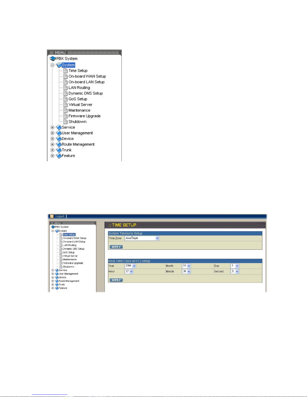
2.1. System
The System setup includes the following configurations
2.1.1. Time Setup
Select System→Time Setup, and you can see the current setting of time zone and
real time clock. The Time Setup page allows to configure time zone and date for IP
PBX.
System time zone setup
Choose the time zone for the IP PBX0, then click APPLY button to save the setting.
Real time clock (RTC) setup
Choose values of year, month, day, hour, minute, and second respectively, then click
APPLY button to save the settings.

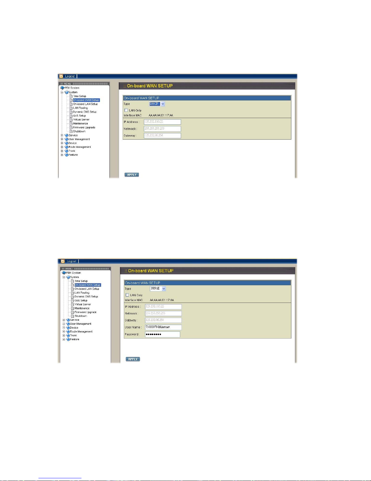
2.1.2. On-board WAN Setup
The WAN setup page allows administrator to configure WAN interface of VOI-9200.
Select System→On-board WAN Setup, to display current setting of WAN interface.
You can select one of three interface types among static IP, DHCP, and PPPoE. The
default type of WAN interface is static IP and the default WAN IP is 192.168.0.1. If
LAN only checkbox is checked, the WAN interface will be disabled.
Static IP
You can choose Static IP in Type list and configure the following information:
IP address
Network mask
Default gateway IP address
Primary and secondary DNS servers
Then click APPLY button to submit.
DHCP
You may choose DHCP in Type list and click APPLY button, and the acquired IP
address, network mask, and default gateway information will be displayed when you
revisit this page later.
PPPoE
Choose PPPoE in Type list and enter the username and password, then click APPLY
button to save your input. The PPPoE dialing will start right away. When the
connection is active, the page will show the acquired IP address, network mask, and
default gateway information. There will also be a Disconnect button to disconnect
connection when desired. Please ask your ISP if you aren’t sure the Username and
Password.
Checkbox: LAN Only
Check checkbox LAN Only to disable WAN IP setting but allow the configuration of
default gateway and primary/secondary DNS servers.
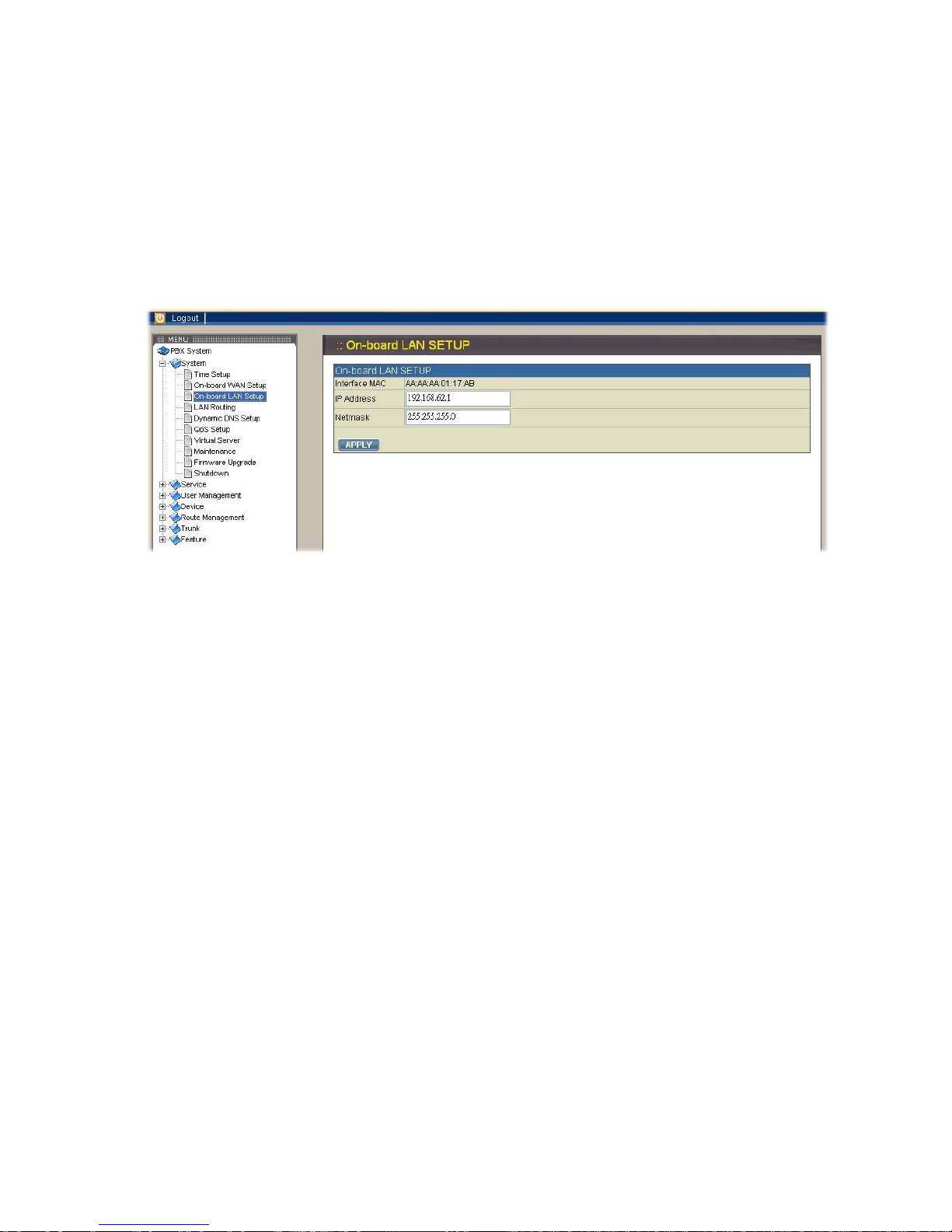
2.1.3. On-board LAN setup
The LAN setup page allows administrator to configure LAN network interface for
VOI-9200. Select System→On-board LAN setup to display the current setting of LAN
interface. The default LAN IP address is 192.168.1.1. You can enter your desired IP
and mask then click APPLY button to save. Note that VOI-9200 IP PBX at default
assigns IP addresses for LAN devices via DHCP server and translates those
addresses into its WAN IP address for access beyond the LAN subnet. As a result,
modifying the system LAN IP subnet must also change DHCP pool and LAN Routing
(if any) accordingly. Besides, IP PBX service must be restarted.
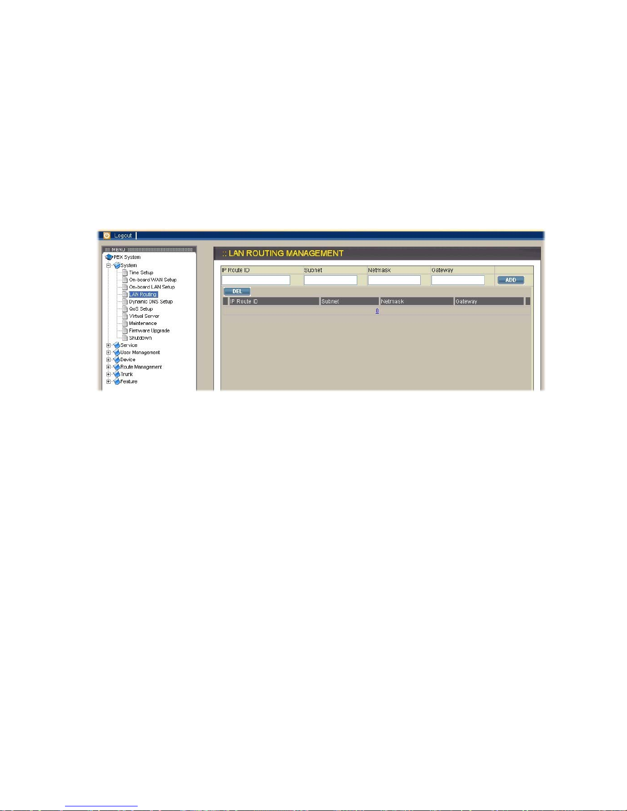
2.1.4. LAN Routing
To enable static routing among LAN subnets, enter the IP address, netmask, and the
gateway IP address for the IP PBX. It is important to assure that the given gateway IP
address is in the same IP PBX’s LAN network. Each subnet requires an entry even
multiple subnets share the same gateway, unless masking does the same. The
examples are adding IP Route IDs net1 and net2 with parameters
192.168.128.0/255.255.255.0, 192.168.129.0/255.255.255.0, shared gateway
192.168.1.254 respectively. Or, IP Route ID net1n2 with
192.168.128.0/255.255.254.0 and gateway 192.168.1.254 would do the same. Added
routes enable routing immediately after clicking APPLY button, however, IP PBX
service needs to be restarted to activate calls from designated LAN subnets.
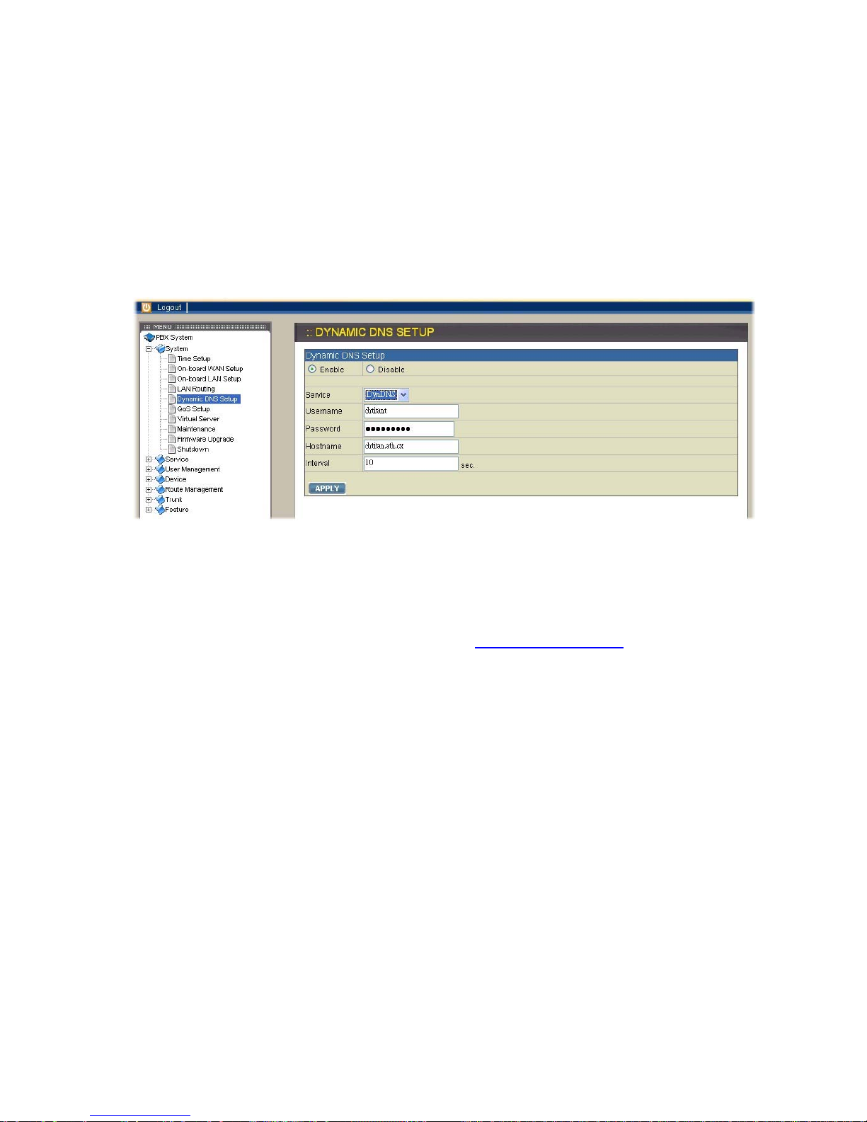
2.1.5. Dynamic DNS Setup
A dynamic WAN IP address causes difficulty for inbound connections from remote
clients for IP PBX systems. A popular work-around is to adopt domain names
provided by a DynDNS server and run a DynDNS client on or behind the gateway
router (or IPPBX). It is required to apply an account first and create a hostname in the
account before configuration. Select System→Dynamic DNS Setup, check Enable
box, and enter the account infomations and refresh interval to activate a DynDNS
client. The client then uses Username and Password to access its account and
update the Hostname with the latest WAN IP address at the DynDNS server in
Interval seconds periodically.
Enable DynDNS
Select Enable button, enter the Username, Password, Hostname, and Interval, and
then click APPLY button. Typical hostname has a form of <hostname>.dyndns.org.
The refresh interval can be from 60 to 600 seconds depending on the volatility of
WAN IP assignment. For example, you can visit http://www.no-ip.com to apply an
account with your own username and password and acquire a hostname, like
VOI-9200.no-ip.org, named by yourself.
Disable DynDNS
Select Disable button, and then click APPLY button.
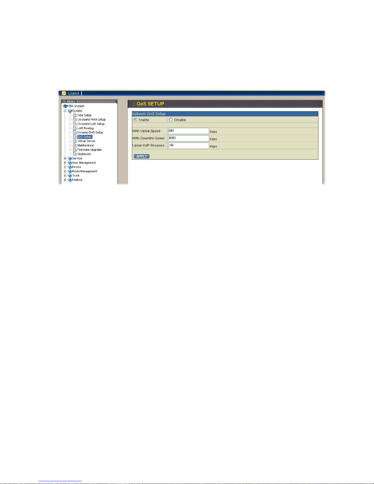
2.1.6. QoS Setup
To assure the bandwidth reserved for the outgoing and incoming VoIP traffic
overriding regular data traffic, you can select System→QoS Setup to access the QoS
Setup page which offers three parameters to characterize the WAN link. These
parameters must be correctly given according to the actual WAN transmission speed.
By default QoS is disabled.
Enable QoS
Select Enable button and enter the values of WAN Uplink Speed, WAN Downlink
Speed, and Uplink VoIP Reserved (bandwidth) respectively, and then click APPLY
button. For example, a 2M/256K ADSL program, the maximum WAN uplink and WAN
downlink speed are 256 kbps and 2048 kbps individually. The Uplink VoIP reserved
could be, say, 192 out of the total 256 kbps to allow 2 concurrent G.711 calls.
Disable QoS
Select Disable button, and then click APPLY button.
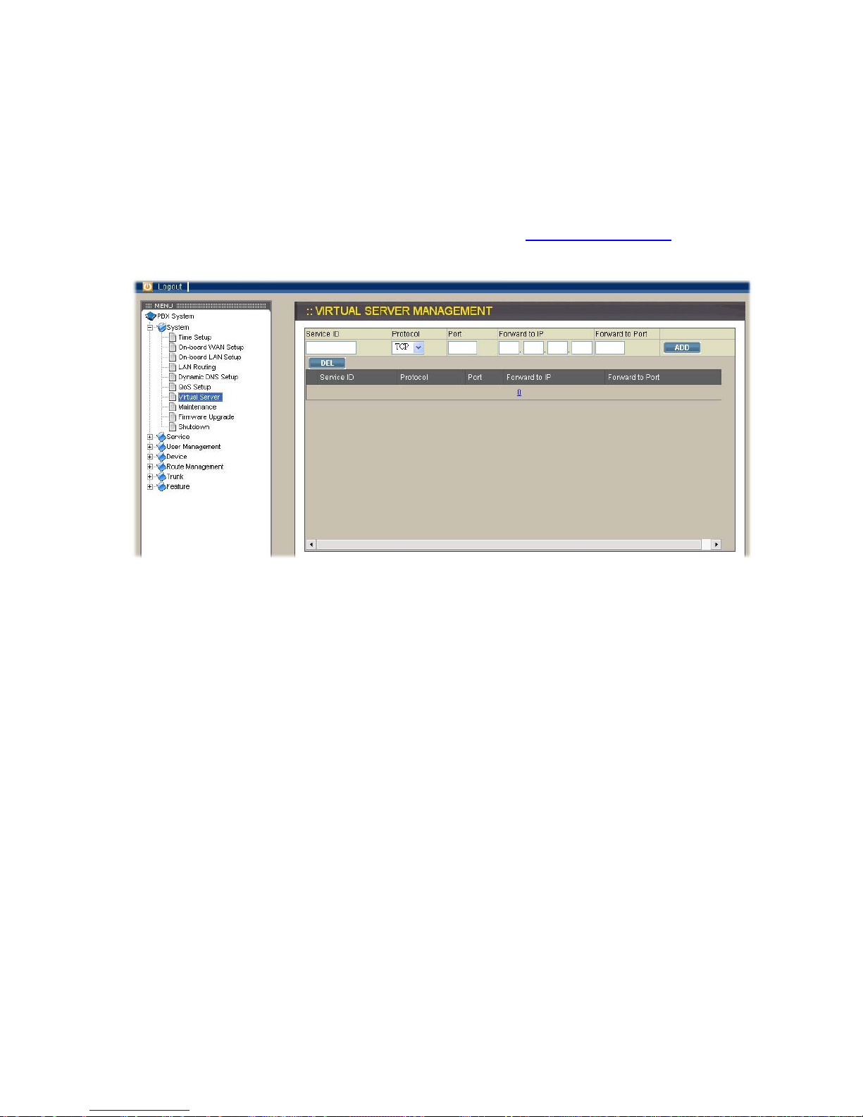
2.1.7. Virtual Server
If you want to access any device behind LAN of VOI-9200 IP PBX from WAN, you
need to select System→Virtual Server to configure port mappings. In virtual server
page, Service ID names the service; Protocol and Port specify the TCP or UDP port
number(s) on WAN IP which will be forwarded to the Forward to port of Forward to IP
in LAN. For example, 192.168.1.5 is a mail server to be seen from outside, one
should configure TCP port 25 to be forwarded to 192.168.1.5 port 25. In other words,
if the WAN IP of VOI-9200 is 192.168.0.1, you can type http://192.168.0.1:25 in your
browser to access the mail server of which IP is 192.168.1.5.
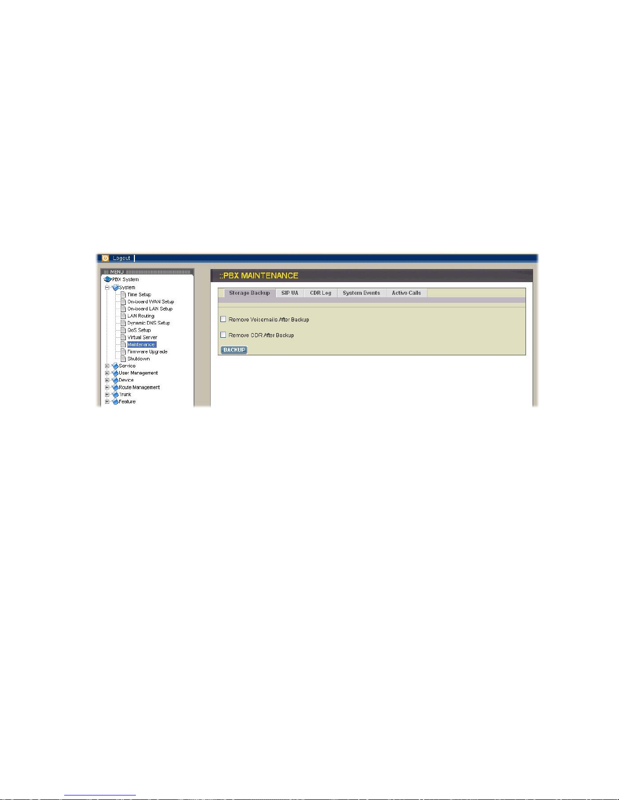
2.1.8. Maintenance
Select System→Maintenance to enter the IP PBX maintenance page to get relative
records of system operation.
Storage Backup
To backup internal main storage, click the BACKUP icon and follow instructions to
insert the USB connector of an external USB drive. There are two checkboxes for
removing either CDR or Voicemails after backup. After a confirmation of the insertion,
backup starts a few seconds later if the external USB drive is accessible and has
enough available capacity. After a successful backup, you can find a new folder
created on the external USB drive. Note that whether the backup is successful or not,
the external USB drive must be removed.
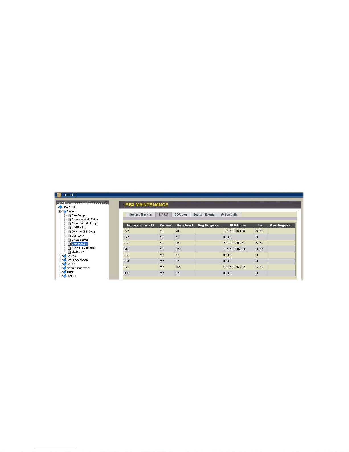
SIP UA
When you click SIP UA tab, it will show a new listing of SIP registration status for
each client. All fields shown in the window are explained as below.
Extension/Trunk ID: show the extension or trunk ID which are also used as SIP
account for registering at VOI-9200 IPPBX
Dynamic: reveal the listed IP address of the corresponding
extension/trunk ID is dynamic or specified
Registered: indicate whether the extension/trunk ID registers successfully
or not
Reg. Progress: display the response code and message if registration has
been attempted but not success so far
IP address: present the IP address of the corresponding extension/trunk
ID
Port: designate which port to be used for SIP connection between
VOI-9200 IPPBX and the SIP device who registered as the
corresponding extension/trunk ID
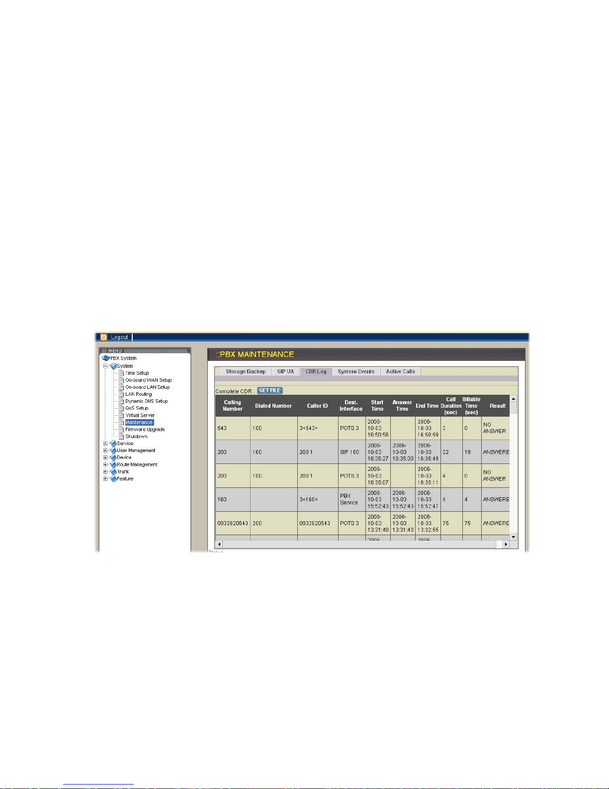
CDR Log
Click CDR Log icon to show the Call Detail Record (CDR) listing each call record in
detail. You can download the complete CDR file by clicking the Get File icon. The
following describes all fields in CDR page.
Calling Number: the extension belonging to the caller
Dialed Number: the complete number that the caller dialed practically
Caller ID: the configured caller ID of the caller
Dest. Interface: the interface of VOI-9200 that this call passed through
Start Time: the time when this call was made
Answer Time: the time when this call was hanged up
End Time: the time when this call was hanged up
Call Duration (sec): the duration from Start Time to End Time
Billable Time (sec): the duration from Answer Time to End Time
Result: show that the call is answered or not
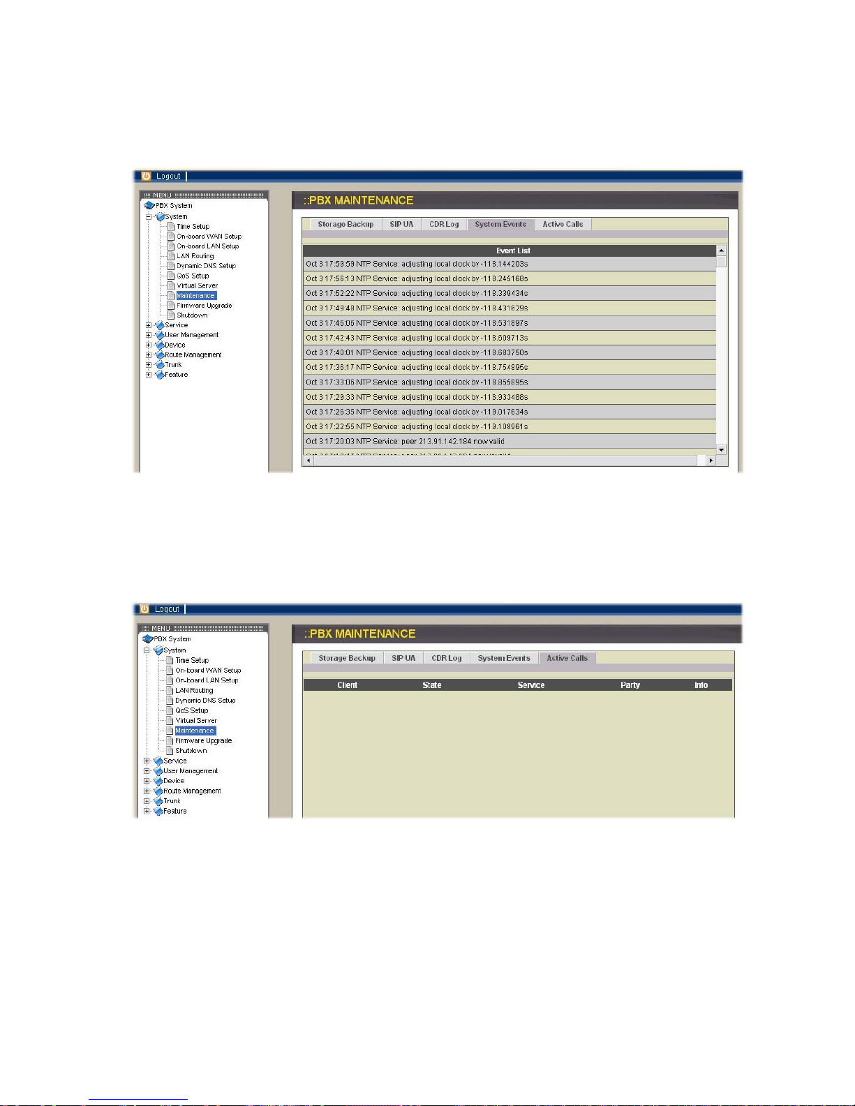
System Events
Event log includes reported events from system services including: NTP, DNS, DHCP,
and PPPoE. You can click System Events icon to see complete records.
Active Calls
Click Active Calls icon to display the active call status.
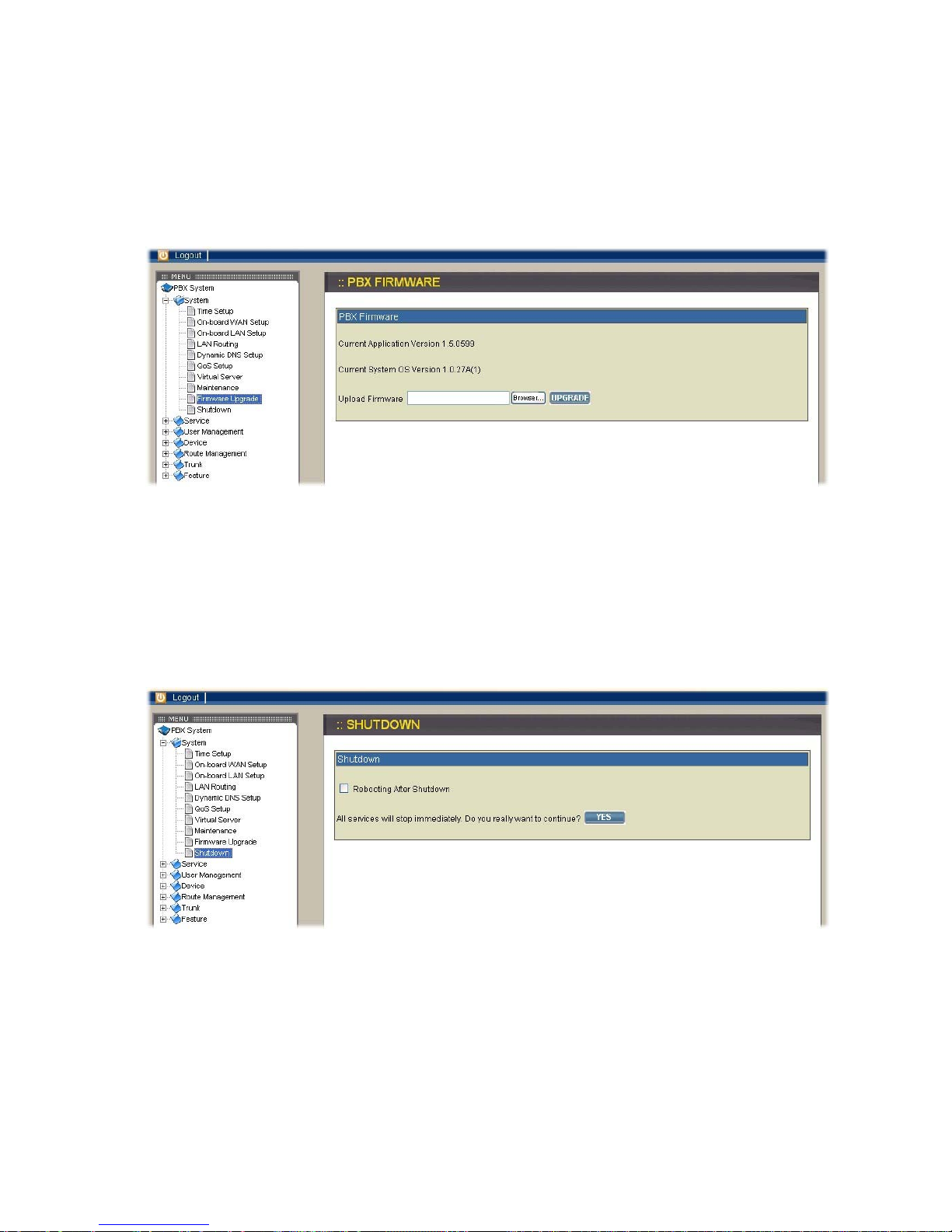
2.1.9. Firmware Upgrade
Select System→Firmware Upgrade and the version of the running PBX firmware
could be found in the page. To upgrade current firmware, you need to locate a
release file obtained from the vendor and then click UPGRADE icon. Note that the
filename of firmware should not be changed; otherwise system will refuse to upgrade
it.
2.1.10. Shutdown
By selecting System→Shutdown, you can shutdown the machine after clicking Yes
icon. If you have checked the checkbox Reboot after shutdown, the system will reboot
after shutdown. Please press and release the hardware reset button quickly to reboot
system in case of unsuccessful software rebooting.
2.2. Service
This chapter describes configurations for various services provided by VOI-9200.
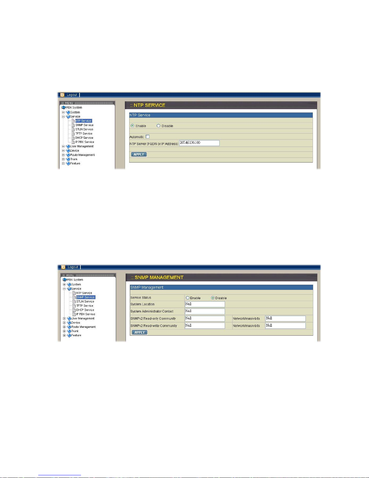
2.2.1. NTP Service
Select Service→NTP Service to specify a NTP server for network time
synchronization. You can enable or disable NTP service at any time.
Enable NTP service
Select Enable button and then enter the fully qualified domain name (FQDN) or the IP
address of a NTP server. Click APPLY icon to save the change.
Disable NTP service
Select Disable button and then click APPLY icon.
2.2.2. SNMP Service
Select Service→SNMP Service to specify Simple Network Management Protocol
(SNMP) parameters for networking status retrieval. You can enable or disable SNMP
service at any time.
Enable SNMP service
Select Enable button then enter the values of System Location, Administrator Contact,
read-only community, and finally click APPLY icon to save the changes. For example,
you can key in the values of snmpserver.xxx.com, irving@xxx.com, and public in turn.
Disable SNMP service
Select Disable button and then click APPLY icon.
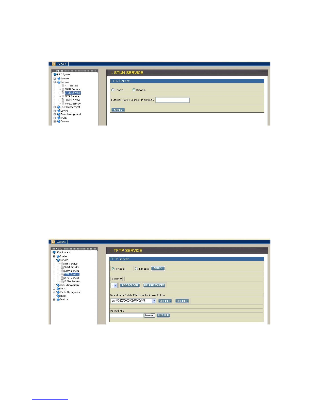
2.2.3. STUN Service
Select Service→STUN Service to specify a Simple Traversal of UDP through NATs
(STUN) server for NAT traversal. You can enable or disable STUN service at any
time.
Enable STUN service
Select Enable button then enter the fully qualified domain name (FQDN) or the IP
address of a STUN server. You have to click APPLY icon to save the change.
Disable STUN service
After selecting Disable button, you can enter the fully qualified domain name (FQDN)
or the static IP address of the external WAN interface if needed and then click APPLY
icon. Usually this address refers to as the static WAN IP address if there is a NAT
device between the IPPBX and Internet. If the WAN port of IPPBX directly connects
to Internet or it is unused, leave the address blank.
2.2.4. TFTP Service
Select Service→TFTP Service to show current status of TFTP service in this page.
You can enable or disable TFTP service at any time.
 Loading...