

Page 1

GSW-4896
48-Port TP with 4-Port shared SFP L2 SNMP Gigabit Switch
User Manual
Ver. 1.01-0711
Page 2

ii
Table of Contents
Caution ................................................................................................................................ v
Electronic Emission Notices............................................................................................... v
1. Introduction.......................................................................................................... 2
1-1. Overview of the switch................................................................................................ 2
1-2. Checklist....................................................................................................................... 4
1-3. Features........................................................................................................................ 4
1-4. View of the switch........................................................................................................ 6
1-4-1. User Interfaces on the Front Panel (Button, LEDs and Plugs) ............................................ 6
1-4-2. User Interfaces on the Rear Panel ....................................................................................... 7
1-5. View of the Optional Modules .................................................................................... 8
2. Installation............................................................................................................9
2-1. Starting the switch Up................................................................................................. 9
2-1-1. Hardware and Cable Installation......................................................................................... 9
2-1-2. Installing Chassis to a 19-Inch Wiring Closet Rail.............................................................11
2-1-3. Cabling Requirements ........................................................................................................11
2-1-4. Configuring the Management Agent of the switch............................................................ 17
2-1-5. IP Address Assignment...................................................................................................... 21
2-2. Typical Applications .................................................................................................. 26
3. Operation of Web-based Management ............................................................. 28
3-1. System......................................................................................................................... 30
3-1-1. System Information ........................................................................................................... 32
3-1-2. IP Configuration................................................................................................................ 34
3-1-3. Time Configuration ........................................................................................................... 37
3-1-4. Account Configuration ...................................................................................................... 40
3-1-5. Management Policy........................................................................................................... 42
3-2. Port Configuration .................................................................................................... 47
3-2-1.Port Status .......................................................................................................................... 47
3-2-2. Port Configuration............................................................................................................. 52
3-2-3. Simple Counter.................................................................................................................. 54
3-2-4. Detail Counter ................................................................................................................... 55
3-3. Storm .......................................................................................................................... 58
3-4. Mirror......................................................................................................................... 59
3-5. Filter ........................................................................................................................... 60
3-5-1. Bad Length ........................................................................................................................ 60
3-5-2. Unknown Encap. ............................................................................................................... 61
3-5-3. Unknown Ether-Type ........................................................................................................ 62
3-5-4. Unknown IP Protocol ........................................................................................................ 63
3-5-5. IPv4 Options...................................................................................................................... 64
3-5-6. Unknown Source ............................................................................................................... 65
3-6. QoS(Quality of Service) Configuration................................................................... 66
Page 3

iii
3-6-1. Priority .............................................................................................................................. 66
3-6-2. Policer ............................................................................................................................... 76
3-6-3. Shaper................................................................................................................................ 77
3-6-4. Flow .................................................................................................................................. 78
3-6-5. Police-Flow ....................................................................................................................... 85
3-6-6. Mark .................................................................................................................................. 86
3-6-7. Mark-enable ...................................................................................................................... 87
3-7. ACL............................................................................................................................. 88
3-7-1. ACL Mode......................................................................................................................... 88
3-7-2. ACL/VLAN Mapping ....................................................................................................... 89
3-7-3. ACL Rule........................................................................................................................... 90
3-8. ACL QoS Load........................................................................................................... 91
3-9. User Defined............................................................................................................... 92
3-10. SNMP Configuration............................................................................................... 93
3-11. IGMP Snooping ....................................................................................................... 99
3-12. Trunk ...................................................................................................................... 103
3-13. STP Configuration..................................................................................................110
3-13-1. STP Status ......................................................................................................................110
3-13-2. STP Configuration..........................................................................................................112
3-13-3. STP Port Configuration ..................................................................................................114
3-14. GVRP Configuration..............................................................................................117
3-15. 802.1X Configuration............................................................................................ 123
3-16. Alarm Configuration............................................................................................. 134
3-17. Configuration......................................................................................................... 137
3-17-2. Config File .................................................................................................................... 143
3-18. Diagnostics ............................................................................................................. 144
3-19. Loop Detection....................................................................................................... 147
3-20. TFTP Server........................................................................................................... 148
3-21. Log .......................................................................................................................... 149
3-22. Firmware Upgrade................................................................................................ 151
3-23. Max. Packet Length .............................................................................................. 152
3-24. MAC Table............................................................................................................. 153
3-25. VLAN...................................................................................................................... 159
3-25-1. VLAN Mode ................................................................................................................. 159
3-25-2. VLAN Group ................................................................................................................ 161
3-25-3. Port Protocol.................................................................................................................. 165
3-25-4. Port VID ........................................................................................................................ 166
3-26. Reboot..................................................................................................................... 167
3-27. Logout..................................................................................................................... 168
4. Operation of CLI Management ....................................................................... 169
4-1. CLI Management .................................................................................................... 169
Page 4

iv
4-1-1. Login ............................................................................................................................... 169
4-2. Commands of CLI................................................................................................... 171
4-2-1. Global Commands of CLI ............................................................................................... 172
4-2-2. Local Commands of CLI ................................................................................................. 178
5. Maintenance ........................................................................................................ 274
5-1. Resolving No Link Condition................................................................................. 274
5-2. Q&A ......................................................................................................................... 274
Appendix A Technical Specifications...................................................................... 275
Appendix B Null Modem Cable Specifications ...................................................... 279
Page 5

v
Caution
Circuit devices are sensitive to static electricity, which can damage their delicate
electronics. Dry weather conditions or walking across a carpeted floor may cause you to
acquire a static electrical charge.
To protect your device, always:
• Touch the metal chassis of your computer to ground the static electrical charge before
you pick up the circuit device.
• Pick up the device by holding it on the left and right edges only.
Electronic Emission Notices
Federal Communications Commission (FCC) Statement
This equipment has been tested and found to comply with the limits for a class A
computing device pursuant to Subpart J of part 15 of FCC Rules, which are designed to
provide reasonable protection against such interference when operated in a commercial
environment.
European Community (CE) Electromagnetic Compatibility Directive
This equipment has been tested and found to comply with the protection requirements
of European Emission Standard EN55022/EN60555-2 and the Generic European Immunity
Standard EN50082-1.
EMC:
EN55022(1988)/CISPR-22(1985) class A
EN60555-2(1995) class A
EN60555-3
IEC1000-4-2(1995) 4K V CD, 8KV, AD
IEC1000-4-3(1995) 3V/m
IEC1000-4-4(1995) 1KV - (power line), 0.5KV - (signal line)
Page 6

Page 7

1
About this user’s manual
This user’s manual provides instructions on how to install your switch.
This guide also covers management options and detailed explanation about
hardware and software functions.
Overview of this user’s manual
Chapter 1 “Introduction” describes the features of the switch
Chapter 2 “Installation”
Chapter 3 “Operation of Web-based Management”
Chapter 4 “Operation of CLI Management”
Chapter 5 “Maintenance”
Page 8

User Manual
2
1. Introduction
1-1. Overview of the switch
The 48-port Gigabit L2 Managed Switch is a L2 management switch that
meets all IEEE 802.3/u/x/z Gigabit, Fast Ethernet specifications. The switch has 44
10/100/1000Mbps TP ports and 4 Gigabit TP/SFP transceiver slots. It supports
console, telnet, http and SNMP interface for switch management. The network
administrator can logon the switch to monitor, configure and control each port’s
activity in a friendly way. The overall network management is enhanced and the
network efficiency is also improved to accommodate high bandwidth applications. In
addition, the switch features comprehensive and useful function such as QoS
(Quality of Service), Spanning Tree, VLAN, Port Trunking, Bandwidth Control, Port
Security, SNMP/RMON, IGMP Snooping capability via the intelligent software. It is
suitable for both metro-LAN and office application.
In this switch, Port 45 to Port 48 include two types of media --- TP and SFP
Fiber (LC, BiDi LC...); this port supports 10/100/1000Mbps TP or 1000Mbps SFP
Fiber with auto-detected function. 1000Mbps SFP Fiber transceiver is used for highspeed connection expansion.
1000Mbps LC, Multi-Mode, SFP Fiber transceiverT
1000Mbps LC, 10km, SFP Fiber transceiverT
1000Mbps LC, 30km, SFP Fiber transceiverT
1000Mbps LC, 50km, SFP Fiber transceiverT
1000Mbps BiDi LC, 20km, 1550nm SFP Fiber WDM transceiver
1000Mbps BiDi LC, 20km, 1310nm SFP Fiber WDM transceiver
T
10/100/1000Mbps TP is a standard Ethernet port that meets all IEEE
802.3/u/x/z Gigabit, Fast Ethernet specifications. 1000Mbps SFP Fiber transceiver
is a Gigabit Ethernet port that fully complies with all IEEE 802.3z and 1000BaseSX/LX standards.
1000Mbps Single Fiber WDM (BiDi) transceiver is designed with an optic
Wavelength Division Multiplexing (WDM) technology that transports bi-directional
full duplex signal over a single fiber simultaneously.
For upgrading firmware, please refer to the Section 3-22 for more details.
The switch will not stop operating while upgrading firmware and after that, the
configuration keeps unchanged.
Page 9

User Manual
3
•
Key Features in the Device
QoS:
Support Quality of Service by the IEEE 802.1P standard. There are two
priority queue and packet transmission schedule.
Spanning Tree:
Support IEEE 802.1D, IEEE 802.1w (RSTP: Rapid Spanning Tree
Protocol) standards.
VLAN:
Support Port-based VLAN and IEEE802.1Q Tag VLAN. Support 256 active
VLANs and VLAN ID 1~4094.
Port Trunking:
Support static port trunking and port trunking with IEEE 802.3ad LACP.
Bandwidth Control:
Support ingress and egress per port bandwidth control.
Port Security:
Support allowed, denied forwarding and port security with MAC address.
SNMP/RMON:
SNMP agent and RMON MIB. In the device, SNMP agent is a client
software which is operating over SNMP protocol used to receive the
command from SNMP manager (server site) and echo the corresponded
data, i.e. MIB object. Besides, SNMP agent will actively issue TRAP
information when happened.
RMON is the abbreviation of Remote Network Monitoring and is a branch of
the SNMP MIB.
The device supports MIB-2 (RFC 1213), Bridge MIB (RFC 1493), RMON
MIB (RFC 1757)-statistics Group 1,2,3,9, Ethernet-like MIB (RFC 1643),
Ethernet MIB (RFC 1643) and so on.
IGMP Snooping:
Support IGMP version 2 (RFC 2236): The function IGMP snooping is used
to establish the multicast groups to forward the multicast packet to the
member ports, and, in nature, avoid wasting the bandwidth while IP
multicast packets are running over the network.
Page 10

User Manual
4
1-2. Checklist
Before you start installing the switch, verify that the package contains the
following:
48-port Gigabit L2 Managed Switch
Modules (optional)
Mounting Accessory (for 19” Rack Shelf)
This User's Manual in CD-ROM
AC Power Cord
RS-232 Cable
Please notify your sales representative immediately if any of the aforementioned
items is missing or damaged.
1-3. Features
The 48-port Gigabit L2 Managed Switch, a standalone off-the-shelf switch,
provides the comprehensive features listed below for users to perform system
network administration and efficiently and securely serve your network.
•
Hardware
• 44 10/100/1000Mbps Auto-negotiation Gigabit Ethernet TP ports
• 4 10/100/1000Mbps TP or 1000Mbps SFP Fiber dual media auto sense
• 400KB on-chip frame buffer
• Jumbo frame support
• Programmable classifier for QoS (Layer 4/Multimedia)
• 8K MAC address and 4K VLAN support (IEEE802.1Q)
• Per-port shaping, policing, and Broadcast Storm Control
• IEEE802.1Q-in-Q nested VLAN support
• Full-duplex flow control (IEEE802.3x) and half-duplex backpressure
• Extensive front-panel diagnostic LEDs; System: Power, TP Port1-48: LINK/ACT,
10/100/1000Mbps, SFP Port 45-48: SFP(LINK/ACT)
•
Management
• Supports concisely the status of port and easily port configuration
• Supports per port traffic monitoring counters
• Supports a snapshot of the system Information when you login
• Supports port mirror function
• Supports the static trunk function
Page 11

User Manual
5
• Supports 802.1Q VLAN
• Supports user management and limits three users to login
• Maximal packet length can be up to 9216 bytes for jumbo frame application
• Supports DHCP Broadcasting Suppression to avoid network suspended or
crashed
• Supports to send the trap event while monitored events happened
• Supports default configuration which can be restored to overwrite the current
configuration which is working on via web browser and CLI
• Supports on-line plug/unplug SFP modules
• Supports Quality of Service (QoS) for real time applications based on the
information taken from Layer 2 to Layer 4, such as VoIP
• Built-in web-based management and CLI management, providing a more
convenient UI for the user
• Supports port mirror function with ingress traffic
• Supports rapid spanning tree (802.1w RSTP)
• Supports 802.1X port security on a VLAN
• Supports user management and only first login administrator can configure the
device. The rest of users can only view the switch
• SNMP access can be disabled and prevent from illegal SNMP access
• Supports Ingress, Non-unicast and Egress Bandwidth rating management with a
resolution of 1Mbps
• The trap event and alarm message can be transferred via e-mail and mobile
phone short message
• Supports diagnostics to let administrator knowing the hardware status
• Supports external loopback test to check if the link is ok
• TFTP for firmware upgrade, system log upload and config file import/export
• Supports remote boot the device through user interface and SNMP
• Supports network time synchronization and daylight saving
• Supports 120 event log records in the main memory and display on the local
console
Page 12
User Manual
6
1-4. View of the switch
1-4-1. User Interfaces on the Front Panel (Button, LEDs and Plugs)
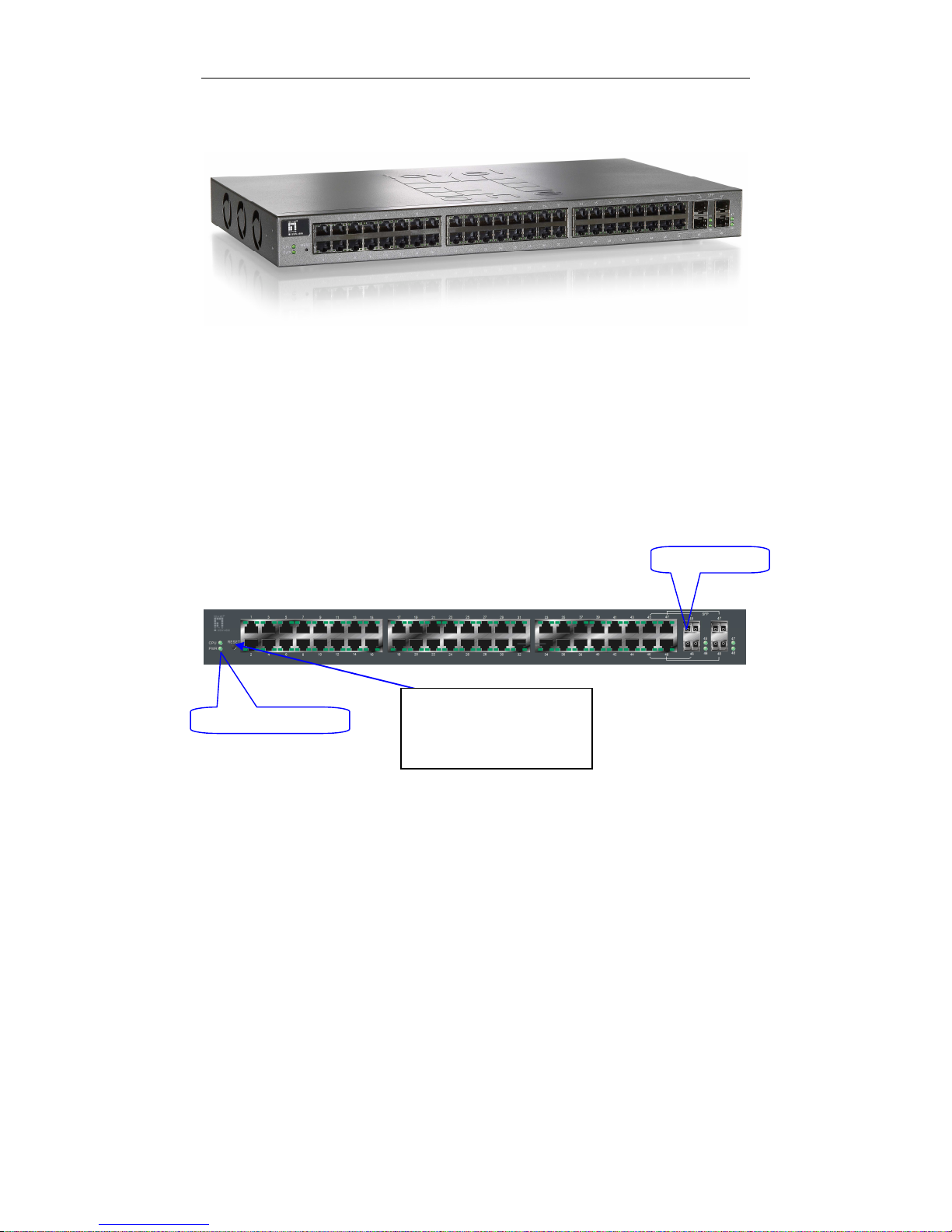
There are 44 TP Gigabit Ethernet ports and 4 SFP fiber ports for optional
removable modules on the front panel of the switch. LED display area, locating on
the left side of the panel, contains a Power LED, which indicates the power status
and 48 ports working status of the switch.
Fig. 1-1 Full View of the switch
Fig. 1-2 Front View of the switch
Power Indication LED
RESET B
utton
:
RESET button is used to
reset the management
system.
SFP Fiber Port
Page 13
User Manual
7
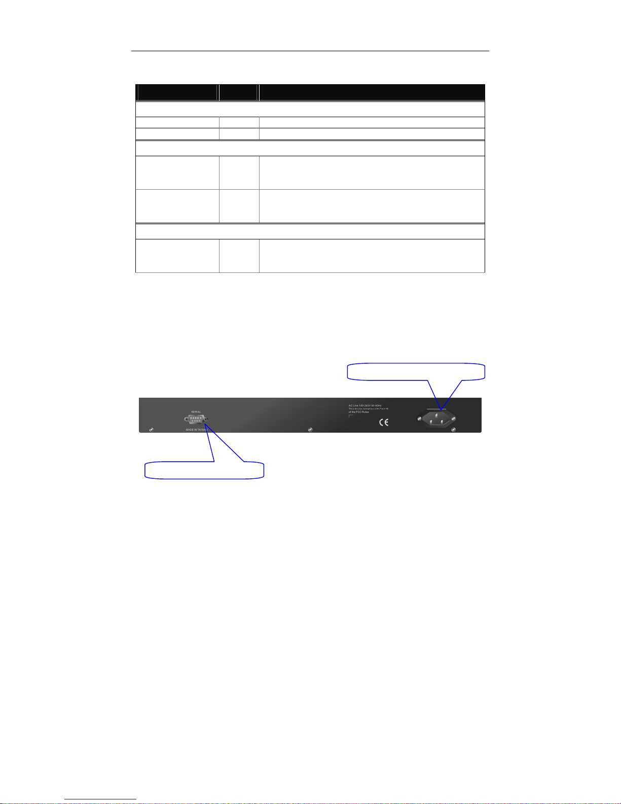
• LED Indicators
LED Color Function
System LED
POWER Green Lit when +5V DC power is on and good
CPU LED Green Blinks when CPU is activity
10/100/1000Ethernet TP Port 1 to 44 LED
LINK/ACT Green
Lit when connection with remote device is good
Blinks when any traffic is present
Off when cable connection is not good
10/100/1000Mbps
Green/
Amber
Lit green when 1000Mbps speed is active
Lit ember when 100Mbps speed is active
Off when 10Mbps speed is active
1000SX/LX Gigabit Fiber Port 45 to 48 LED
SFP(LINK/ACT) Green
Lit when connection with the remote device is good
Blinks when any traffic is present
Off when module connection is not good
Table1-1
T
1-4-2. User Interfaces on the Rear Panel
One RS-232 DB-9 interface is offered for configuration or management.
Fig. 1-3 Rear View of the switch
RS-232 DB
-
9 Connector
AC Lin
e 100
-
240V 50/60 Hz
Page 14
User Manual
8
1-5. View of the Optional Modules
In the switch, Port 45~48 include two types of media --- TP and SFP Fiber
(LC, BiDi LC...); they support 10/100/1000Mbps TP or 1000Mbps SFP Fiber with
auto-detected function. 1000Mbps SFP Fiber transceiver is used for high-speed
connection expansion; the following are optional SFP types provided for the switch:
1000Mbps LC, MM, SFP Fiber transceiverT (SFP.0LC.202)T
1000Mbps LC, SM 10km, SFP Fiber transceiverT (SFP.0LC.212.10)T
1000Mbps LC, SM 30km, SFP Fiber transceiverT (SFP.0LC.212.30)T
1000Mbps LC, SM 50km, SFP Fiber transceiverT (SFP.0LC.212.50)T
1000Mbps BiDi LC, type 1, SM 20km, SFP Fiber WDM transceiver
T(SFP.0BL.621.201)T
1000Mbps BiDi LC, type 2, SM 20km, SFP Fiber WDM transceiver
T(SFP.0BL.621.202)T
1000Mbps LC, SM 10km, SFP Fiber transceiverT with DDM
(SFP.DLC.212.10)
T
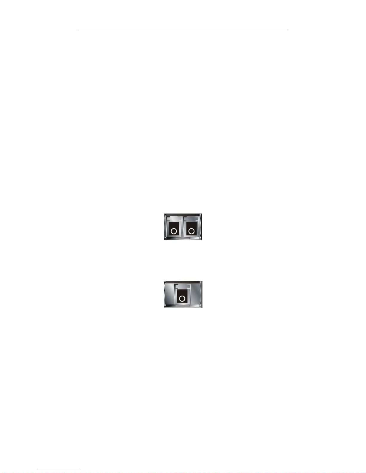
Fig. 1-4 Front View of 1000Base-SX/LX LC, SFP Fiber Transceiver
Fig. 1-5 Front View of T1000Base-LX BiDi LC, SFP Fiber Transceiver
T
Page 15

User Manual
9
2. Installation
2-1. Starting the switch Up
This section will give users a quick start for:
-
Hardware and Cable Installation
- Management Station Installation
- Software booting and configuration
2-1-1. Hardware and Cable Installation
At the beginning, please do first:
⇒ Wear a grounding device to avoid the damage from electrostatic discharge
⇒ Be sure that power switch is OFF before you insert the power cord to power
source
• To install Optional
T
SFP TFiber Transceivers to the switch
T
Note: If you have no modules, please skip this section.
• Connecting the SFP Module to the Chassis:
The optional SFP modules are hot swappable, so you can plug or unplug it
before or after powering on.
1. Verify that the SFP module is the right model and conforms to the chassis
2. Slide the module along the slot. Also be sure that the module is properly
seated against the slot socket/connector
3. Install the media cable for network connection
4. Repeat the above steps, as needed, for each module to be installed into
slot(s)
5. Have the power ON after the above procedures are done
Fig. 2
-1
Installation of
O
ptional
SFP Fiber
T
ransceiver
Page 16

User Manual
10
•
T
TP Port and Cable Installation
T
⇒ In the switch, TP port supports MDI/MDI-X auto-crossover, so both types of
cable, straight-through (Cable pin-outs for RJ-45 jack 1, 2, 3, 6 to 1, 2, 3, 6 in
10/100M TP; 1, 2, 3, 4, 5, 6, 7, 8 to 1, 2, 3, 4, 5, 6, 7, 8 in Gigabit TP) and
crossed-over (Cable pin-outs for RJ-45 jack 1, 2, 3, 6 to 3, 6, 1, 2) can be used.
It means you do not have to tell from them, just plug it.
⇒ Use Cat. 5 grade RJ-45 TP cable to connect to a TP port of the switch and the
other end is connected to a network-aware device such as a workstation or a
server.
⇒ Repeat the above steps, as needed, for each RJ-45 port to be connected to a
Gigabit 10/100/1000 TP device.
Now, you can start having the switch in operation.
• TPower On
T
The switch supports 100-240 VAC, 50-60 Hz power supply. The power
supply will automatically convert the local AC power source to DC power. It does not
matter whether any connection plugged into the switch or not when power on, even
modules as well. After the power is on, all LED indicators will light up immediately
and then all off except the power LED still keeps on. This represents a reset of the
system.
• Firm
T
ware Loading
T
After resetting, the bootloader will load the firmware into the memory. It will
take about 30 seconds, after that, the switch will flash all the LED once and
automatically performs self-test and is in ready state.
Page 17

User Manual
11
2-1-2. Installing Chassis to a 19-Inch Wiring Closet Rail
Caution: Allow a proper spacing and proper air ventilation for the cooling fan
at both sides of the chassis.
⇒
Wear a grounding device for electrostatic discharge.
⇒
Screw the mounting accessory to the front side of the switch (See Fig. 2-2).
⇒
Place the Chassis into the 19-inch wiring closet rail and locate it at the proper
position. Then, fix the Chassis by screwing it.
2-1-3. Cabling Requirements
To help ensure a successful installation and keep the network performance
good, please take a care on the cabling requirement. Cables with worse
specification will render the LAN to work poorly.
Fig. 2-2
Page 18

User Manual
12
2-1-3-1. Cabling Requirements for TP Ports
⇒ For Fast Ethernet TP network connection
The grade of the cable must be Cat. 5 or Cat. 5e with a maximum length of
100 meters.
⇒ Gigabit Ethernet TP network connection
The grade of the cable must be Cat. 5 or Cat. 5e with a maximum length of
100 meters. Cat. 5e is recommended.
2-1-3-2. Cabling Requirements for 1000SX/LX SFP Module
It is more complex and comprehensive contrast to TP cabling in the fiber
media. Basically, there are two categories of fiber, multi mode (MM) and single
mode (SM). The later is categorized into several classes by the distance it supports.
They are SX, LX, LHX, XD, and ZX. From the viewpoint of connector type, there
mainly are LC and BIDI LC.
Gigabit Fiber with multi-mode LC SFP module
Gigabit Fiber with single-mode LC SFP module
Gigabit Fiber with BiDi LC 1310nm SFP module
Gigabit Fiber with BiDi LC 1550nm SFP module
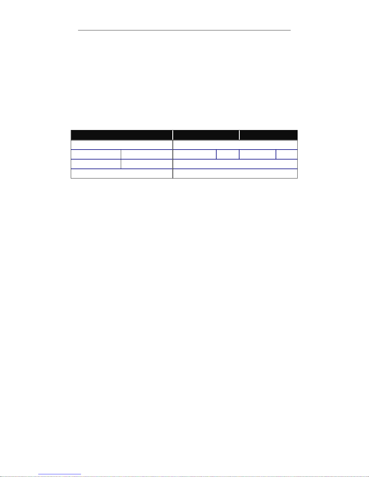
The following table lists the types of fiber that we support and those else not
listed here are available upon request.
Multi-mode Fiber Cable and Modal Bandwidth
Multi-mode 62.5/125µm Multi-mode 50/125µm
Modal
Bandwidth
Distance
Modal
Bandwidth
Distance
160MHz-Km 220m 400MHz-Km 500m
IEEE 802.3z
Gigabit Ethernet
1000SX 850nm
200MHz-Km 275m 500MHz-Km 550m
Single-mode Fiber 9/125µm
Single-mode transceiver 1310nm 10Km
1000BaseLX/LHX/XD/ZX
Single-mode transceiver 1550nm 30, 50Km
TX(Transmit) 1310nm
Single-Mode
*20Km
RX(Receive) 1550nm
TX(Transmit) 1550nm
1000Base-LX
Single Fiber
(BIDI LC)
Single-Mode
*20Km
RX(Receive) 1310nm
Table2-1
Page 19
User Manual
13
2-1-3-3. Switch Cascading in Topology
• Takes the Delay Time into Account
Theoretically, the switch partitions the collision domain for each port in switch
cascading that you may up-link the switches unlimitedly. In practice, the network
extension (cascading levels & overall diameter) must follow the constraint of the
IEEE 802.3/802.3u/802.3z and other 802.1 series protocol specifications, in which
the limitations are the timing requirement from physical signals defined by 802.3
series specification of Media Access Control (MAC) and PHY, and timer from some
OSI layer 2 protocols such as 802.1d, 802.1q, LACP and so on.
The fiber, TP cables and devices’ bit-time delay (round trip) are as follows:
1000Base-X TP, Fiber 100Base-TX TP 100Base-FX Fiber
Round trip Delay: 4096 Round trip Delay: 512
Cat. 5 TP Wire:
11.12/m Cat. 5 TP Wire:
1.12/m
Fiber Cable: 1.0/m
Fiber Cable : 10.10/m TP to fiber Converter: 56
Bit Time unit : 1ns (1sec./1000 Mega bit)
Bit Time unit: 0.01µs (1sec./100 Mega bit)
Table 2-2
Sum up all elements’ bit-time delay and the overall bit-time delay of
wires/devices must be within Round Trip Delay (bit times) in a half-duplex network
segment (collision domain). For full-duplex operation, this will not be applied. You
may use the TP-Fiber module to extend the TP node distance over fiber optic and
provide the long haul connection.
• Typical Network Topology in Deployment
A hierarchical network with minimum levels of switch may reduce the timing
delay between server and client station. Basically, with this approach, it will
minimize the number of switches in any one path; will lower the possibility of
network loop and will improve network efficiency. If more than two switches are
connected in the same network, select one switch as Level 1 switch and connect all
other switches to it at Level 2. Server/Host is recommended to connect to the Level
1 switch. This is general if no VLAN or other special requirements are applied.
Page 20
User Manual
14
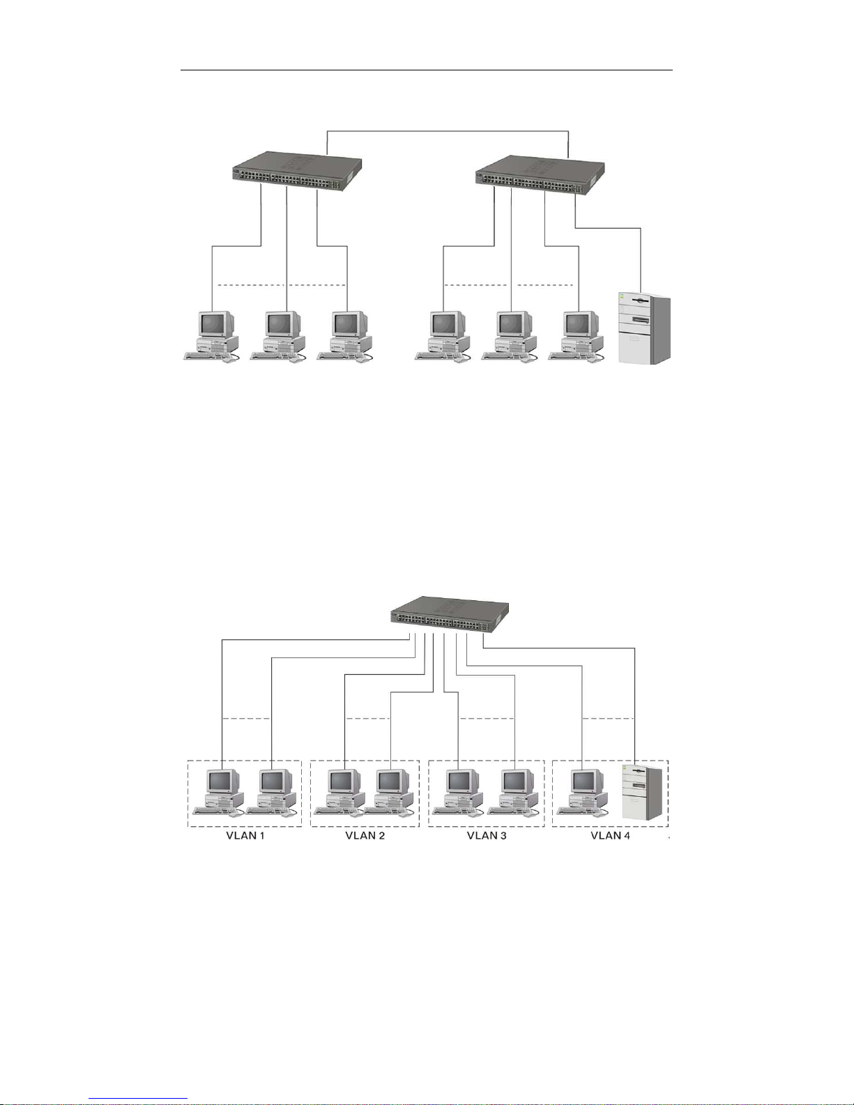
Case1: All switch ports are in the same local area network. Every port can access
each other (See Fig. 2-3).
If VLAN is enabled and configured, each node in the network that can
communicate each other directly is bounded in the same VLAN area.
Here VLAN area is defined by what VLAN you are using. The switch
supports both port-based VLAN and tag-based VLAN. They are different in practical
deployment, especially in physical location. The following diagram shows how it
works and what the difference they are.
Case2a: Port-based VLAN (See Fig.2-4).
1. The same VLAN members could not be in different switches.
Fig. 2
-3
No VLAN Configuration Diagram
Fig. 2-4 Port-based VLAN Diagram
Page 21

User Manual
15
2. Every VLAN members could not access VLAN members each other.
3. The switch manager has to assign different names for each VLAN groups
at one switch.
Page 22
User Manual
16
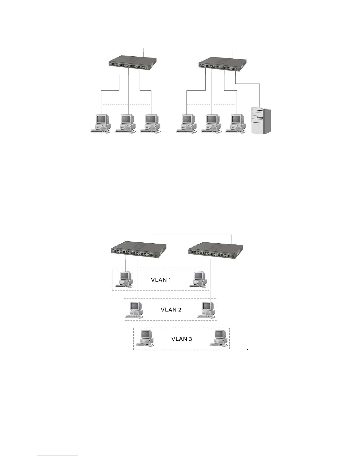
Case 2b: Port-based VLAN (See Fig.2-5).
1. VLAN1 members could not access VLAN2, VLAN3 and VLAN4 members.
2. VLAN2 members could not access VLAN1 and VLAN3 members, but they could
access VLAN4 members.
T3.T
VLAN3 members could not access VLAN1, VLAN2 and VLAN4.
4. VLAN4 members could not access VLAN1 and VLAN3 members, but they could
access VLAN2 members.
Case3a: The same VLAN members can be at different switches with the same VID
(See Fig. 2-6).
T
Fig. 2-5 Port-based VLAN Diagram
Fig. 2-6 Attribute-based VLAN Diagram
Page 23

User Manual
17
T
2-1-4. Configuring the Management Agent of the switch
T
We offer you three ways to startup the switch management function. They are RS232 console, CLI, and Web. Users can use any one of them to monitor and
configure the switch. You can touch them through the following procedures.
T
Section 2-1-4-1: TConfiguring the Management Agent of the switch through the
Serial RS-232 Port
T
Section 2-1-4-2: TConfiguring the Management Agent of the switch through the
Ethernet Port
T
Note: Please first modify the IP address, Subnet mask, Default gateway and DNS
through RS-232 console, and then do the next.
Page 24
User Manual
18
2-1-4-1. Configuring the Management Agent of the switch through the Serial
RS-232 Port
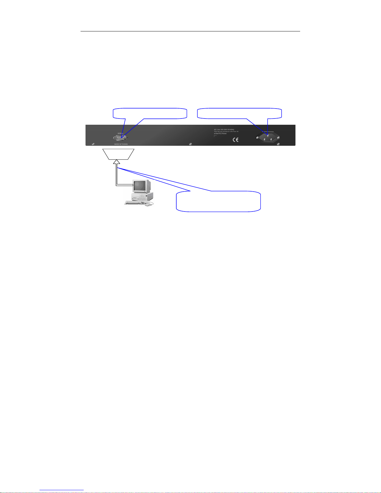
To perform the configuration through RS-232 console port, the switch’s serial
port must be directly connected to a DCE device, for example, a PC, through
RS-232 cable with DB-9 connector. Next, run a terminal emulator with the default
setting of the switch’s serial port. With this, you can communicate with the switch.
In the switch, RS-232 interface only supports baud rate 57.6k bps with 8 data
bits, 1 stop bit, no parity check and no flow control.
To configure the switch, please follow the procedures below:
1.
Find the RS-232 DB-9 cable with female DB-9 connector bundled.
Normally, it just uses pins 2, 3 and 7. See also Appendix B for more
details on Null Modem Cable Specifications.
2.
Attaches the DB-9 female cable connector to the male serial RS-232
DB-9 connector on the switch.
3.
Attaches the other end of the serial RS-232 DB-9 cable to PC’s serial
port, running a terminal emulator supporting VT100/ANSI terminal with
The switch’s serial port default settings. For example,
Windows98/2000/XP HyperTerminal utility.
Note: The switch’s serial port default settings are listed as follows:
Baud rate 115200
Stop bits 1
Data bits 8
Parity N
Flow control none
4.
When you complete the connection, then press <Enter> key. The login
prompt will be shown on the screen. The default username and
password are shown as below:
Username = admin Password = admin
48-port L2 SNMP Managed Switch
Default IP Setting:
IP address = 192.168.1.1
Subnet Mask = 255.255.255.0
Default Gateway = 192.168.1.254
Terminal or Terminal Emulator
Fig. 2-7
RS-232 cable with female
DB-9 connector at both ends
RS-232
AC Line 100
-
240V 50/60 Hz
RS-232 DB
-
9 Connector
Page 25
User Manual
19
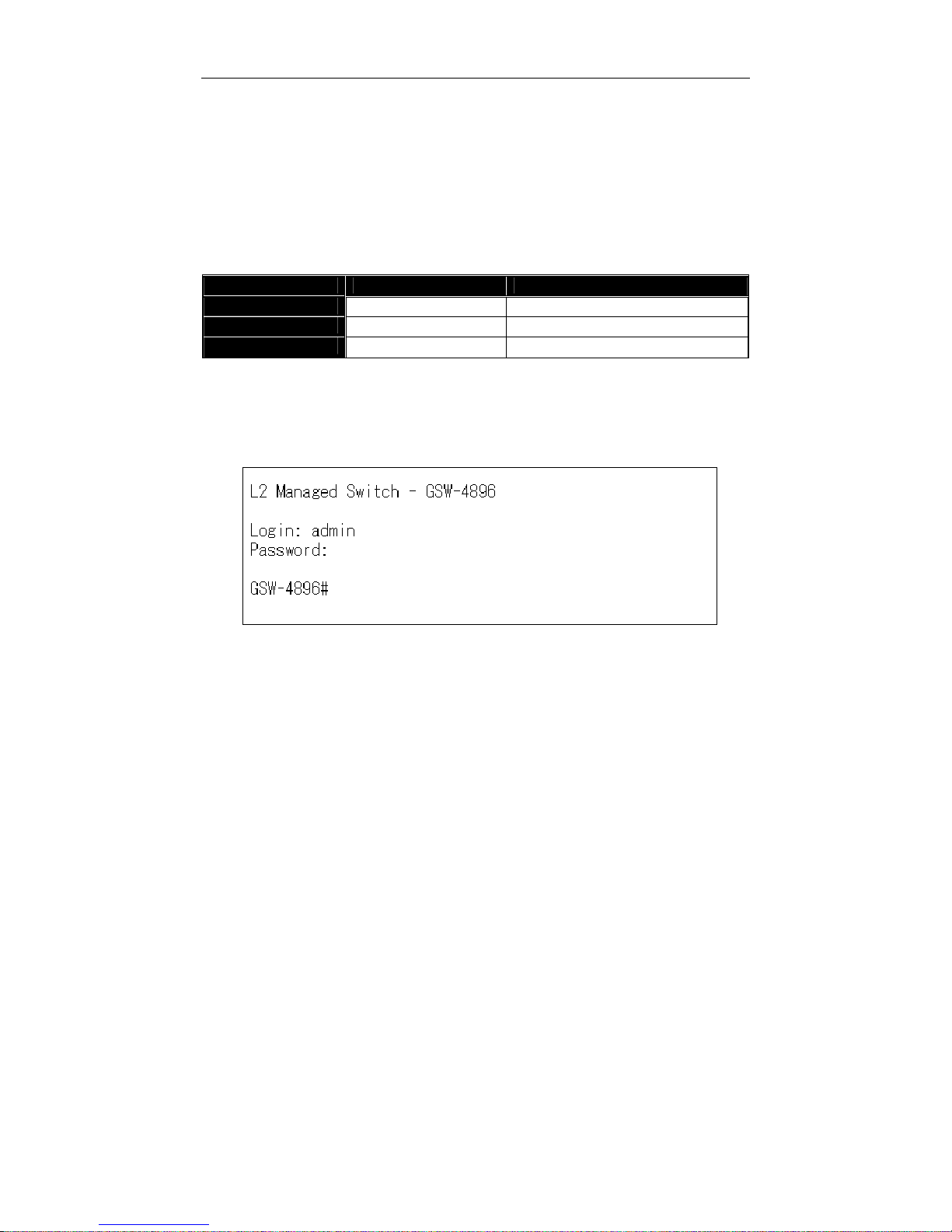
• Set IP Address, Subnet Mask and Default Gateway IP Address
Please refer to Fig. 2-7 CLI Management for details. They are default setting
of IP address. You can first either configure your PC IP address or change IP
address of the switch, next to change the IP address of default gateway and subnet
mask.
T
For example, your network address is 10.1.1.0, and subnet mask is 255.255.255.0.
You can change the switch’s default IP address 192.168.1.1 to 10.1.1.1 and set the
subnet mask to be 255.255.255.0. Then, choose your default gateway, may be it is
10.1.1.254.
TT
Default Value Switch Your Network Setting
IP Address
192.168.1.1
10.1.1.1
Subnet
255.255.255.0
255.255.255.0
Default Gateway
192.168.1.254
10.1.1.254
Table 2-3
After completing these settings in the switch, it will reboot to have the
configuration taken effect. After this step, you can operate the management through
the network, no matter it is from a web browser or Network Management System
(NMS).
Fig. 2-8 the Login Screen for CLI
T
Page 26
User Manual
20
2-1-4-2. Configuring the Management Agent of the switch through the
Ethernet Port
There are three ways to configure and monitor the switch through the
switch’s Ethernet port. They are CLI, Web browser and SNMP manager. The user
interface for the last one is NMS dependent and does not cover here. We just
introduce the first two types of management interface.
• Managing the switch through Ethernet Port
Before you communicate with the switch, you have to finish first the
configuration of the IP address or to know the IP address of the switch. Then,
follow the procedures listed below.
1. Set up a physical path between the configured the switch and a PC by a
qualified UTP Cat. 5 cable with RJ-45 connector.
Note: If PC directly connects to the switch, you have to setup the same
subnet mask between them. But, subnet mask may be different for the PC
in the remote site. Please refer to Fig. 2-9 about the switch’s default IP
address information.
2. Run CLI or web browser and follow the menu. Please refer to Chapter 3
and Chapter 4.
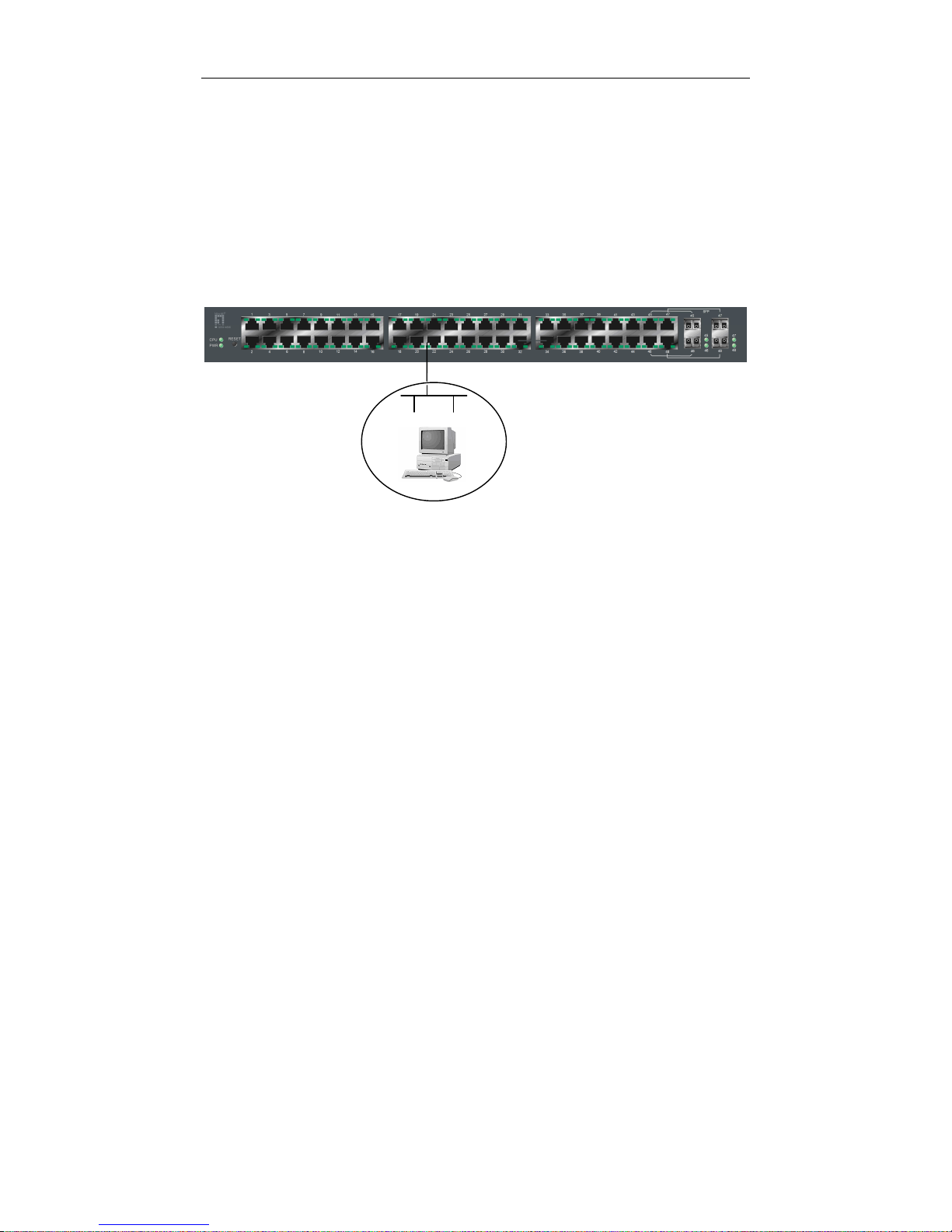
48-port L2 Managed Switch
Default IP Setting:
IP = 192.168.1.1
Subnet Mask = 255.255.255.0
Default Gateway = 192.168.1.254
Assign a reasonable IP address,
For example:
IP = 192.168.1.100
Subnet Mask = 255.255.255.0
Default Gateway = 192.168.1.254
Fig. 2
-9
Ethernet LAN
Page 27
User Manual
21
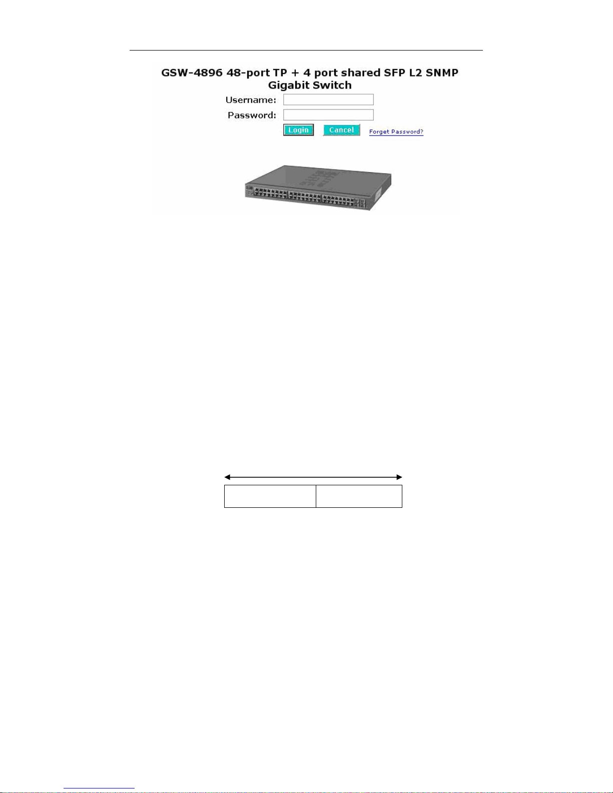
Fig. 2-10
T
the Login Screen for Web
T
2-1-5. IP Address Assignment
For IP address configuration, there are three parameters needed to be filled
in. They are IP address, Subnet Mask, Default Gateway and DNS.
IP address:
The address of the network device in the network is used for internetworking
communication. Its address structure looks is shown in the Fig. 2-11. It is “classful”
because it is split into predefined address classes or categories.
Each class has its own network range between the network identifier and
host identifier in the 32 bits address. Each IP address comprises two parts: network
identifier (address) and host identifier (address). The former indicates the network
where the addressed host resides, and the latter indicates the individual host in the
network which the address of host refers to. And the host identifier must be unique
in the same LAN. Here the term of IP address we used is version 4, known as IPv4.
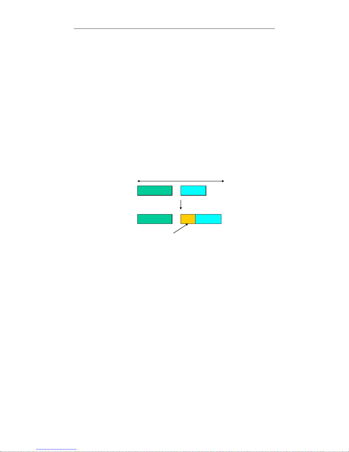
Network identifier Host identifier
Fig. 2-11 IP address structure
32 bits
Page 28

User Manual
22
With the classful addressing, it divides IP address into three classes, class A,
class B and class C. The rest of IP addresses are for multicast and broadcast. The
bit length of the network prefix is the same as that of the subnet mask and is
denoted as IP address/X, for example, 192.168.1.0/24. Each class has its address
range described below.
Class A:
Address is less than 126.255.255.255. There are a total of 126 networks can
be defined because the address 0.0.0.0 is reserved for default route and
127.0.0.0/8 is reserved for loopback function.
0
Class B:
IP address range between 128.0.0.0 and 191.255.255.255. Each class B
network has a 16-bit network prefix followed 16-bit host address. There are 16,384
(2^14)/16 networks able to be defined with a maximum of 65534 (2^16 -2) hosts per
network.
10
Class C:
IP address range between 192.0.0.0 and 223.255.255.255. Each class C
network has a 24-bit network prefix followed 8-bit host address. There are
2,097,152 (2^21)/24 networks able to be defined with a maximum of 254 (2^8 -2)
hosts per network.
110
Bit # 0 1 7 8 31
Network address Host address
Bit # 01 2 15 16 31
Network address Host address
Bit # 0 1 2 3 23 24 31
Network address Host address
Page 29

User Manual
23
Class D and E:
Class D is a class with first 4 MSB (Most significance bit) set to 1-1-1-0 and
is used for IP Multicast. See also RFC 1112. Class E is a class with first 4 MSB set
to 1-1-1-1 and is used for IP broadcast.
According to IANA (Internet Assigned Numbers Authority), there are three
specific IP address blocks reserved and able to be used for extending internal
network. We call it Private IP address and list below:
Class A 10.0.0.0 --- 10.255.255.255
Class B 172.16.0.0 --- 172.31.255.255
Class C 192.168.0.0 --- 192.168.255.255
Please refer to RFC 1597 and RFC 1466 for more information.
Subnet mask:
It means the sub-division of a class-based network or a CIDR block. The
subnet is used to determine how to split an IP address to the network prefix and the
host address in bitwise basis. It is designed to utilize IP address more efficiently and
ease to manage IP network.
For a class B network, 128.1.2.3, it may have a subnet mask 255.255.0.0 in
default, in which the first two bytes is with all 1s. This means more than 60
thousands of nodes in flat IP address will be at the same network. It’s too large to
manage practically. Now if we divide it into smaller network by extending network
prefix from 16 bits to, say 24 bits, that’s using its third byte to subnet this class B
network. Now it has a subnet mask 255.255.255.0, in which each bit of the first
three bytes is 1. It’s now clear that the first two bytes is used to identify the class B
network, the third byte is used to identify the subnet within this class B network and,
of course, the last byte is the host number.
Not all IP address is available in the sub-netted network. Two special
addresses are reserved. They are the addresses with all zero’s and all one’s host
number. For example, an IP address 128.1.2.128, what IP address reserved will be
looked like? All 0s mean the network itself, and all 1s mean IP broadcast.
10000000.00000001.00000010.1 0000000
25 bits
1 0000000
1 1111111
All 0s = 128.1.2.128
All 1s= 128.1.2.255
Subnet
Network
Page 30

User Manual
24
In this diagram, you can see the subnet mask with 25-bit long,
255.255.255.128, contains 126 members in the sub-netted network. Another is that
the length of network prefix equals the number of the bit with 1s in that subnet mask.
With this, you can easily count the number of IP addresses matched. The following
table shows the result.
Prefix Length
No. of IP matched
No. of Addressable IP
/32
1 -
/31
2 -
/30
4 2
/29
8 6
/28
16
14
/27
32
30
/26
64
62
/25
128
126
/24
256
254
/23
512
510
/22
1024
1022
/21
2048
2046
/20
4096
4094
/19
8192
8190
/18
16384
16382
/17
32768
32766
/16
65536
65534
Table 2-4
According to the scheme above, a subnet mask 255.255.255.0 will partition a
network with the class C. It means there will have a maximum of 254 effective
nodes existed in this sub-netted network and is considered a physical network in an
autonomous network. So it owns a network IP address which may looks like
168.1.2.0.
With the subnet mask, a bigger network can be cut into small pieces of
network. If we want to have more than two independent networks in a network, a
partition to the network must be performed. In this case, subnet mask must be
applied.
Page 31
User Manual
25
For different network applications, the subnet mask may look like
255.255.255.240. This means it is a small network accommodating a maximum of
15 nodes in the network.
Default gateway:
For the routed packet, if the destination is not in the routing table, all the
traffic is put into the device with the designated IP address, known as default router.
Basically, it is a routing policy. The gateway setting is used for Trap Events Host
only in the switch.
For assigning an IP address to the switch, you just have to check what the IP
address of the network will be connected with the switch. Use the same network
address and append your host address to it.
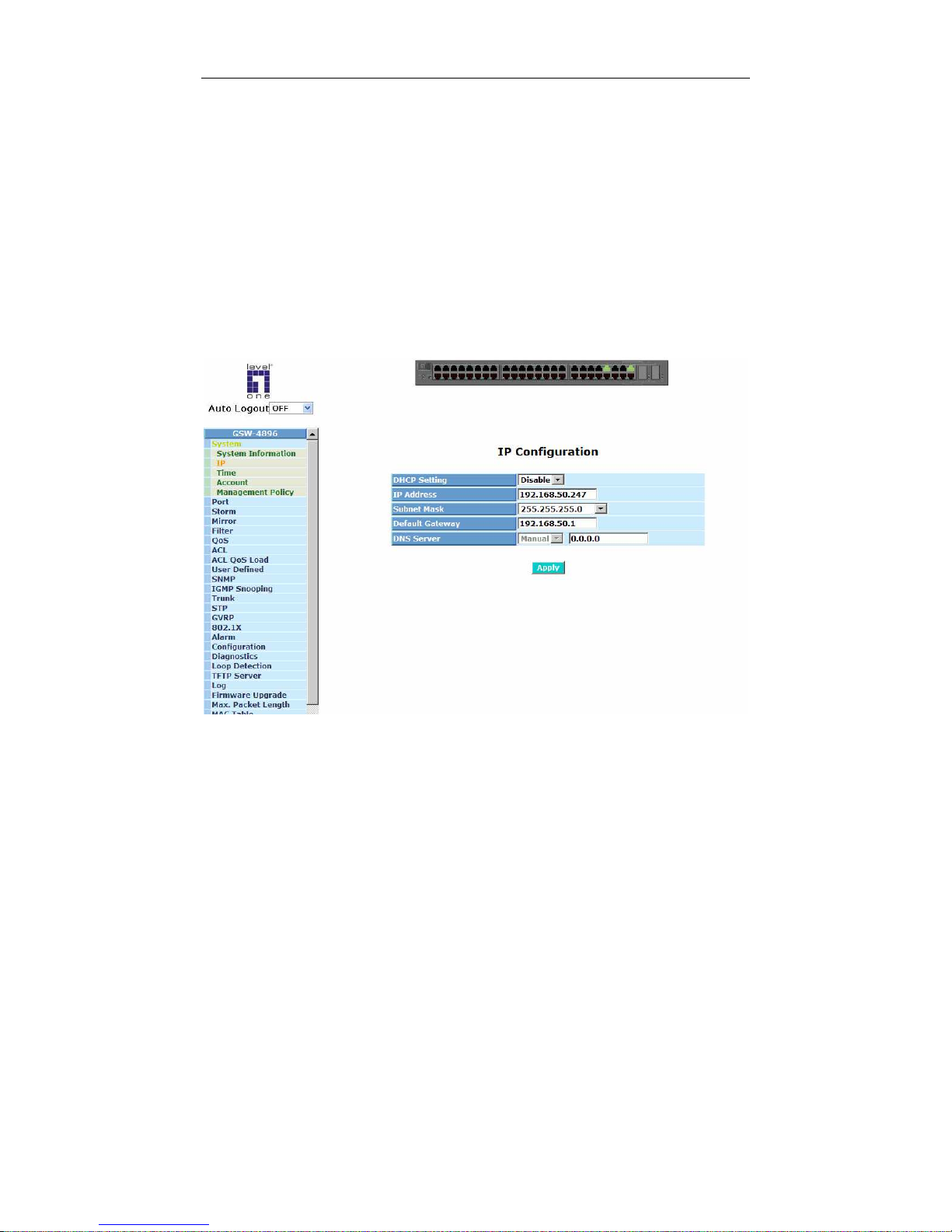
Fig. 2-12
First, IP Address: as shown in the Fig. 2-12, enter “192.168.1.1”, for instance.
For sure, an IP address such as 192.168.1.x must be set on your PC.
Second, Subnet Mask: as shown in the Fig. 2-12, enter “255.255.255.0”. Any
subnet mask such as 255.255.255.x is allowable in this case.
DNS:
The Domain Name Server translates human readable machine name to IP
address. Every machine on the Internet has a unique IP address. A server generally
has a static IP address. To connect to a server, the client needs to know the IP of
the server. However, user generally uses the name to connect to the server. Thus,
the switch DNS client program (such as a browser) will ask the DNS to resolve the
IP address of the named server.
Page 32
User Manual
26
2-2. Typical Applications
The switch implements 48 Gigabit Ethernet TP ports with auto MDIX and two
slots for the removable module supporting comprehensive fiber types of connection,
including LC and BiDi-LC SFP modules. For more details on the specification of the
switch, please refer to Appendix A.
The switch is suitable for the following applications.
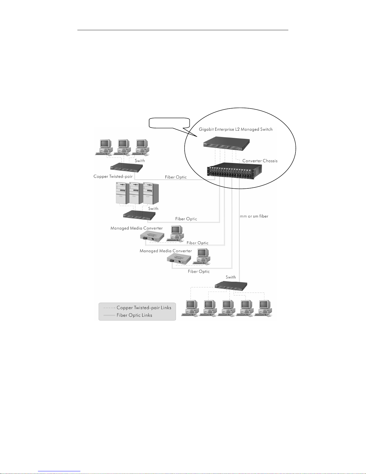
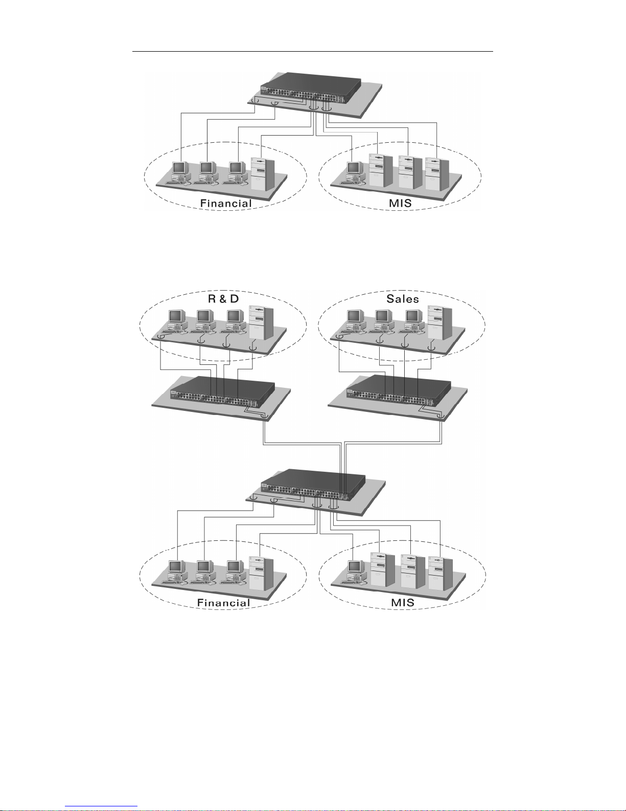
Central Site/Remote site application is used in carrier or ISP (See Fig. 2-13)
Peer-to-peer application is used in two remote offices (See Fig. 2-14)
Office network(See Fig. 2-15)
Fig. 2-13 is a system wide basic reference connection diagram. This diagram
demonstrates how the switch connects with other network devices and hosts.
Fig. 2-13 Network Connection between Remote Site and Central Site
Central Site
Page 33
User Manual
27
Fig. 2-15 Office Network Connection
Fig. 2-14 Peer-to-peer Network Connection
Page 34

User Manual
28
3. Operation of
Web-based Management
T
This chapter instructs you how to configure and manage the switchT Tthrough the
web user interface it supports, to access and manage the T44-Port
10/100/1000Mbps TP and 4-Port Gigabit TP/SFP Fiber management Ethernet
switch. T With this facility, you can easily access and monitor through any one port of
the switch all the status of the switch, including MIBs status, each port activity,
Spanning tree status, port aggregation status, multicast traffic, VLAN and priority
status, even illegal access record and so on.
The default values of the managed switch are listed in the table below:
IP Address
192.168.1.1
Subnet Mask
255.255.255.0
Default Gateway
192.168.1.254
Username
admin
Password
admin
Table 3-1
After the managed switch has been finished configuration in the CLI via the
switch’s serial interface, you can browse it. For instance, type
HTU
http://192.168.1.1
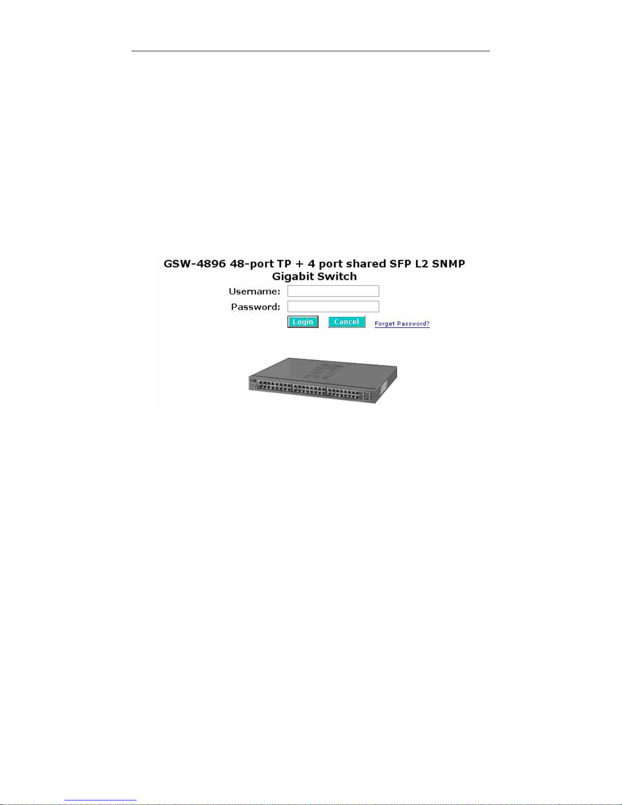
UTH
in
the address row in a browser, it will show the following screen (see Fig.3-1) and ask
you inputting username and password in order to login and access authentication.
The default username and password are both “admin”. For the first time to use,
please enter the default username and password, then click the <Login> button.
The login process now is completed.
Just click the link of “Forget Password” in WebUI (See Fig. 3-1) or input
“Ctrl+Z” in CLI’s login screen (See Fig. 4-1~4-2) in case the user forgets the
manager’s password. Then, the system will display a serial No. for the user. Write
down this serial No. and contact your vendor, the vendor will give you a temporary
password. Use this new password as ID and Password, and it will allow the user to
login the system with manager authority temporarily. Due to the limit of this new
password, the user only can login the system one time, therefore, please modify
your password immediately after you login in the system successfully.
In this login menu, you have to input the complete username and password
respectively, the switch will not give you a shortcut to username automatically. This
looks inconvenient, but safer.
Page 35
User Manual
29
In the switch, it supports a simple user management function allowing only
one administrator to configure the system at the same time. If there are two or more
users using administrator’s identity, the switch will allow the only one who logins first
to configure the system. The rest of users, even with administrator’s identity, can
only monitor the system. For those who have no administrator’s identity, can only
monitor the system. There are only a maximum of three users able to login
simultaneously in the switch.
To optimize the display effect, we recommend you use Microsoft IE 6.0
above, Netscape V7.1 above or FireFox V1.00 above and have the resolution
1024x768. The switch supports neutral web browser interface.
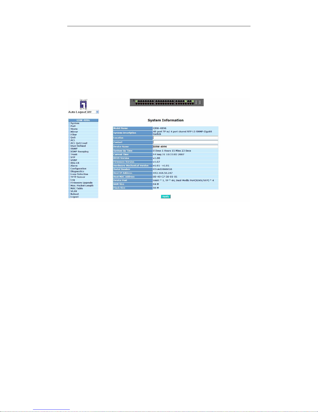
In Fig. 3-2, for example, left section is the whole function tree with web user
interface and we will travel it through this chapter.
Fig. 3-1
Page 36
User Manual
30
T
3-1. System
After you login, the switch shows you the system information as Fig. 3-2. This
page is default and tells you the basic information of the system, including “Model
Name”, “System Description”, “Location”, “Contact”, “Device Name”, “System Up
Time”, “Current Time”, “BIOS Version”, “Firmware Version”, “Hardware-Mechanical
Version”, “Serial Number”, “Host IP Address”, “Host Mac Address”, “Device Port”,
“RAM Size” and “Flash Size”. With this information, you will know the software
version used, MAC address, serial number, how many ports good and so on. This is
helpful while malfunctioning.
Fig. 3-2
Page 37
User Manual
31
•
The Information of Page Layout
On the top side, it shows the front panel of the switch. In the front panel, the
linked ports will display green; as to the ports, which are link off, they will be
dark. For the optional modules, the slot will show only a cover plate if no
module exists and will show a module if a module is present. The image of
module depends on the one you inserted. The same, if disconnected, the port
will show just dark, if linked, green.
In this device, there are clicking functions on the panel provided for the
information of the ports. These are very convenient functions for browsing the
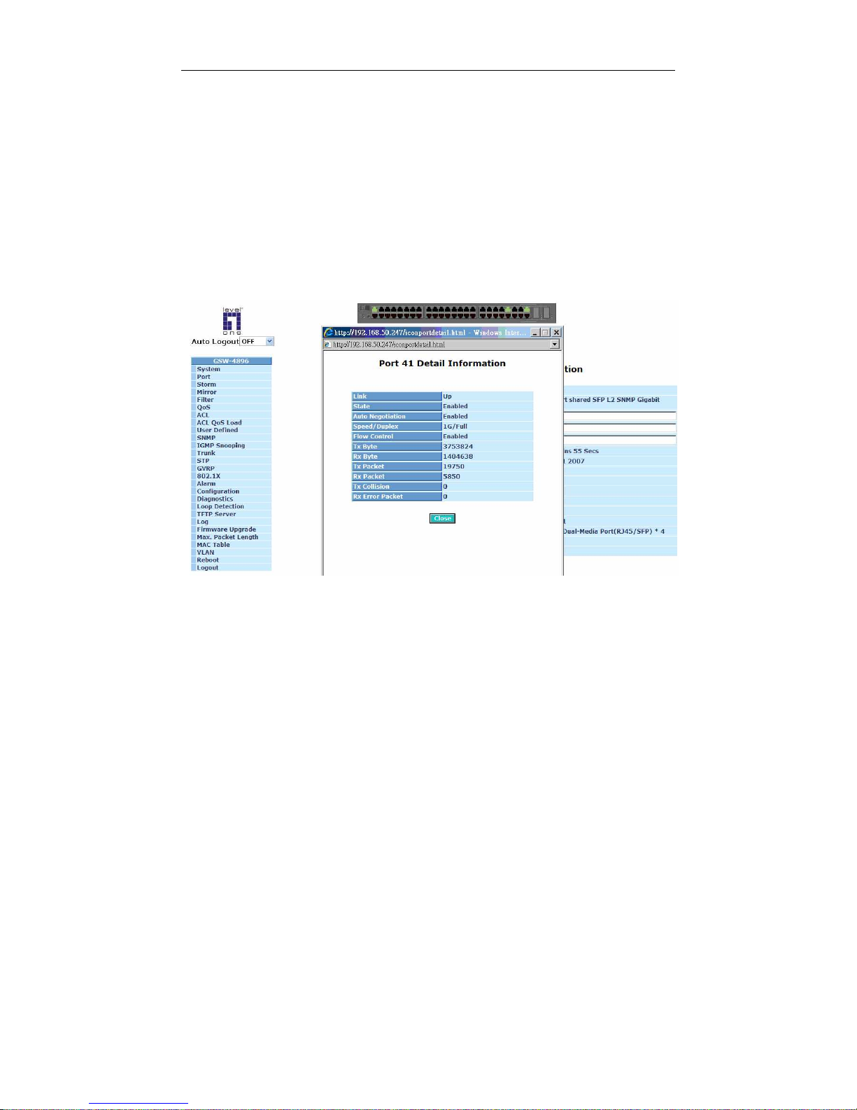
information of a single port. When clicking the port on the front panel, an
information window for the port will be pop out. (See Fig. 3-3)
Fig. 3-3 port detail information
In Fig. 3-3, it shows the basic information of the clicked port. With this, you’ll
see the information about the port status, traffic status and bandwidth rating for
egress and ingress respectively.
On the left-top corner, there is a pull-down list for Auto Logout. For the sake of
security, we provide auto-logout function to protect you from illegal user as you
are leaving. If you do not choose any selection in Auto Logout list, it means
you turn on the Auto Logout function and the system will be logged out
automatically when no action on the device 3 minutes later. If OFF is chosen,
the screen will keep as it is. Default is ON.
On the left side, the main menu tree for web is listed in the page. They are
hierarchical menu. Open the function folder, a sub-menu will be shown. The
functions of each folder are described in its corresponded section respectively.
When clicking it, the function is performed.
Page 38

User Manual
32
3-1-1. System Information
Function name:
System Information
Function description:
Show the basic system information.
Parameter description:
Model name:
The model name of this device.
System description:
As it is, this tells what this device is. Here, it is “L2 Managed Switch”.
Location:
Basically, it is the location where this switch is put. User-defined.
Contact:
For easily managing and maintaining device, you may write down the
contact person and phone here for getting help soon. You can configure
this parameter through the device’s user interface or SNMP.
Device name:
The name of the switch. User-defined. Default is GSW-4896.
System up time:
The time accumulated since this switch is powered up. Its format is day,
hour, minute, second.
Current time:
Show the system time of the switch. Its format: day of week, month, day,
hours : minutes : seconds, year. For instance, Wed, Apr. 23, 12:10:10,
2004.
BIOS version:
The version of the BIOS in this switch.
Firmware version:
The firmware version in this switch.
Hardware-Mechanical version:
The version of Hardware and Mechanical. The figure before the hyphen
is the version of electronic hardware; the one after the hyphen is the
version of mechanical.
Serial number:
The serial number is assigned by the manufacturer.
Page 39

User Manual
33
Host IP address:
The IP address of the switch.
Host MAC address:
It is the Ethernet MAC address of the management agent in this switch.
Device Port:
Show all types and numbers of the port in the switch.
RAM size:
The size of the DRAM in this switch.
Flash size:
The size of the flash memory in this switch.
Page 40
User Manual
34
3-1-2. IP Configuration
IP configuration is one of the most important configurations in the switch.
Without the proper setting, network manager will not be able to manage or view the
device. The switch supports both manual IP address setting and automatic IP
address setting via DHCP server. When IP address is changed, you must reboot the
switch to have the setting taken effect and use the new IP to browse for web
management and CLI management.
TT
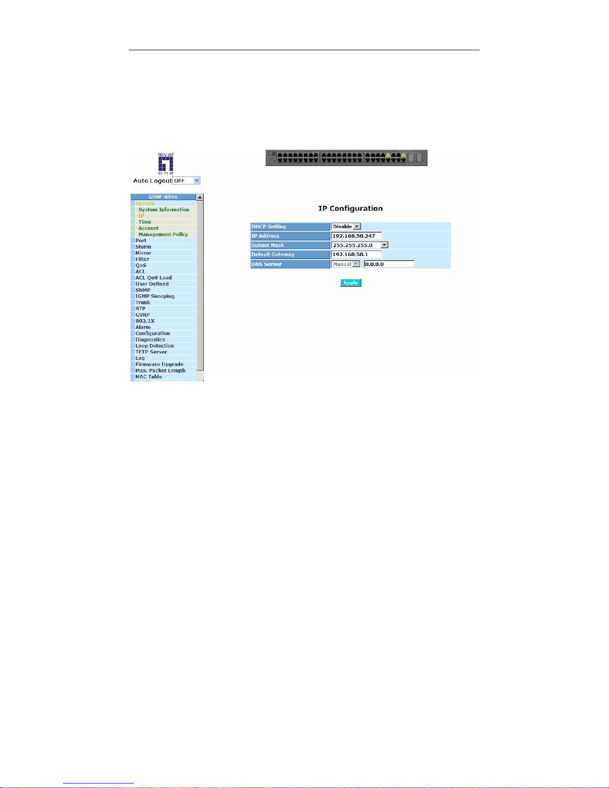
Fig. 3-4 IP Address Configuration
Function name:
IP Configuration
Function description:
Set IP address, subnet mask, default gateway and DNS for the switch.
Parameter description:
DHCP Setting:
DHCP is the abbreviation of Dynamic Host Configuration Protocol. Here
DHCP means a switch to turn ON or OFF the function.
The switch supports DHCP client used to get an IP address automatically
if you set this function “Enable”. When enabled, the switch will issue the
request to the DHCP server resided in the network to get an IP address.
If DHCP server is down or does not exist, the switch will issue the
request and show IP address is under requesting, until the DHCP server
is up. Before getting an IP address from DHCP server, the device will not
continue booting procedures. If set this field “Disable”, you’ll have to
input IP address manually. For more details about IP address and DHCP,
please see the Section 2-1-5 “IP Address Assignment” in this manual.
Default: Disable
Page 41
User Manual
35
IP address:
Users can configure the IP settings and fill in new values if users set the
DHCP function “Disable”. Then, click <Apply> button to update.
When DHCP is disabled, Default: 192.168.1.1
If DHCP is enabled, this field is filled by DHCP server and will not allow
user manually set it any more.
Subnet mask:
Subnet mask is made for the purpose to get more network address
because any IP device in a network must own its IP address, composed
of Network address and Host address, otherwise can’t communicate with
other devices each other. But unfortunately, the network classes A, B,
and C are all too large to fit for almost all networks, hence, subnet mask
is introduced to solve this problem. Subnet mask uses some bits from
host address and makes an IP address looked Network address, Subnet
mask number and host address. It is shown in the following figure. This
reduces the total IP number of a network able to support, by the amount
of 2 power of the bit number of subnet number (2^(bit number of subnet
number)).
Subnet mask is used to set the subnet mask value, which should be the
same value as that of the other devices resided in the same network it
attaches.
For more information, please also see the Section 2-1-5 “IP Address
Assignment” in this manual.
Default: 255.255.255.0
Default gateway:
Set an IP address for a gateway to handle those packets that do not
meet the routing rules predefined in the device. If a packet does not meet
the criteria for other pre-defined path, it must be forwarded to a default
router on a default path. This means any packet with undefined IP
address in the routing table will be sent to this device unconditionally.
Default: 192.168.1.254
32 bits
Network ID
Host ID
Network ID
Host ID
Subnet number
Page 42

User Manual
36
DNS Server:
It is Domain Name Server used to serve the translation between IP
address and name address.
The switch supports DNS client function to re-route the mnemonic name
address to DNS server to get its associated IP address for accessing
Internet. User can specify a DNS IP address for the switch. With this, the
switch can translate a mnemonic name address into an IP address.
There are two ways to specify the IP address of DNS. One is fixed mode,
which manually specifies its IP address, the other is dynamic mode,
which is assigned by DHCP server while DHCP is enabled. DNS can
help you easily remember the mnemonic address name with the
meaningful words in it. Default is no assignment of DNS address.
Default: 0.0.0.0
Page 43

User Manual
37
3-1-3. Time Configuration
The switch provides manual and automatic ways to set the system time via
NTP. Manual setting is simple and you just input “Year”, “Month”, “Day”, “Hour”,
“Minute” and “Second” within the valid value range indicated in each item. If you
input an invalid value, for example, 61 in minute, the switch will clamp the figure to
59.
NTP is a well-known protocol used to synchronize the clock of the switch
system time over a network. NTP, an internet draft standard formalized in
HT
RFC
1305TH, has been adopted on the system is version 3 protocol. The switch provides
four built-in NTP server IP addresses resided in the Internet and an user-defined
NTP server IP address. The time zone is Greenwich-centered which uses the
expression form of GMT+/- xx hours.
Function name:
Time
Function description:
Set the system time by manual input or set it by syncing from Time servers.
The function also supports daylight saving for different area’s time adjustment.
Parameter description:
Current Time:
Show the current time of the system.
Manual:
This is the function to adjust the time manually. Filling the valid figures in
the fields of Year, Month, Day, Hour, Minute and Second respectively and
press <Apply> button, time is adjusted. The valid figures for the
parameter Year, Month, Day, Hour, Minute and Second are >=2000, 1-12,
1-31, 0-23, 0-59 and 0-59 respectively. Input the wrong figure and press
<Apply> button, the device will reject the time adjustment request. There
is no time zone setting in Manual mode.
NTP:
NTP is Network Time Protocol and is used to sync the network time
based Greenwich Mean Time (GMT). If use the NTP mode and select a
built-in NTP time server or manually specify an user-defined NTP server
as well as Time Zone, the switch will sync the time in a short after
pressing <Apply> button. Though it synchronizes the time automatically,
NTP does not update the time periodically without user’s processing.
Time Zone is an offset time off GMT. You have to select the time zone
first and then perform time sync via NTP because the switch will combine
this time zone offset and updated NTP time to come out the local time,
otherwise, you will not able to get the correct time. The switch supports
configurable time zone from -12 to +13 step 1 hour.
Default Time zone: +8 Hrs.
Daylight Saving:
Daylight saving is adopted in some countries. If set, it will adjust the time
lag or in advance in unit of hours, according to the starting date and the
Page 44

User Manual
38
ending date. For example, if you set the day light saving to be 1 hour.
When the time passes over the starting time, the system time will be
increased one hour after one minute at the time since it passed over. And
when the time passes over the ending time, the system time will be
decreased one hour after one minute at the time since it passed over.
The switch supports valid configurable day light saving time is -5 ~ +5
step one hour. The zero for this parameter means it need not have to
adjust current time, equivalent to in-act daylight saving. You don’t have to
set the starting/ending date as well. If you set daylight saving to be nonzero, you have to set the starting/ending date as well; otherwise, the
daylight saving function will not be activated.
Default for Daylight Saving: 0.
The following parameters are configurable for the function Daylight
Saving and described in detail.
Day Light Saving Start :
This is used to set when to start performing the day light saving time.
Mth:
Range is 1 ~ 12.
Default: 1
Day:
Range is 1 ~ 31.
Default: 1
Hour:
Range is 0 ~ 23.
Default: 0
Day Light Saving End :
This is used to set when to stop performing the daylight saving time.
Mth:
Range is 1 ~ 12.
Default: 1
Day:
Range is 1 ~ 31.
Default: 1
Hour:
Range is 0 ~ 23.
Default: 0
Page 45
User Manual
39
T
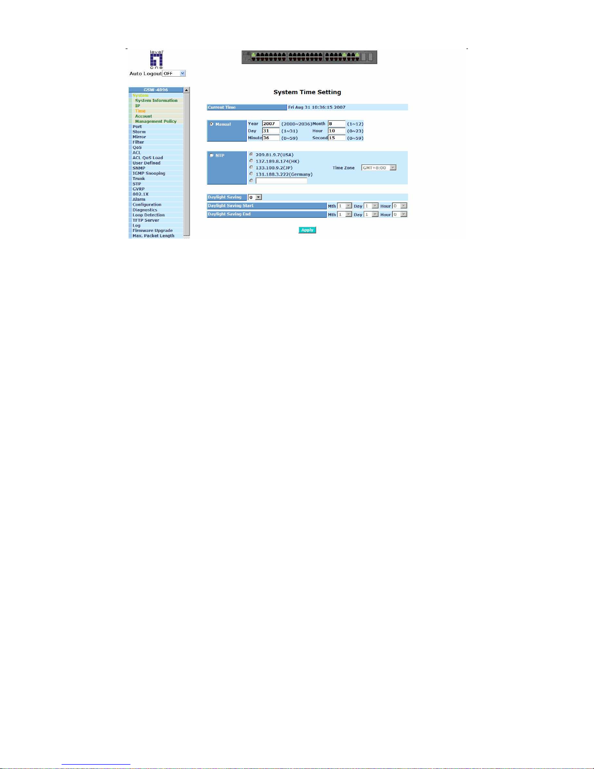
Fig. 3-5
Page 46

User Manual
40
3-1-4. Account Configuration
In this function, only administrator can create, modify or delete the username
and password. Administrator can modify other guest identities’ password without
confirming the password but it is necessary to modify the administrator-equivalent
identity. Guest-equivalent identity can modify his password only. Please note that
you must confirm administrator/guest identity in the field of Authorization in advance
before configuring the username and password. Only one administrator is allowed
to exist and unable to be deleted. In addition, up to 4 guest accounts can be created.
The default setting for user account is:
Username : admin
Password : admin
The default setting for guest user account is:
Username : guest
Password : guest
Function name:
Account Configuration
Function description:
Configure existing accounts.
Parameter description:
Create New:
Create a new account.
Edit:
Edit an existing account.
Delete:
Delete an existing account.
Page 47
User Manual
41
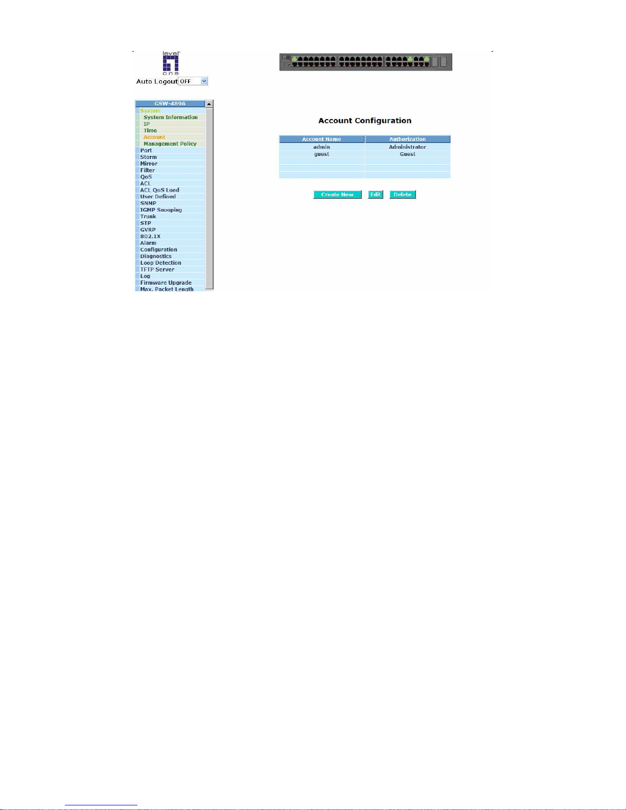
Fig. 3-6
Page 48

User Manual
42
3-1-5. Management Policy
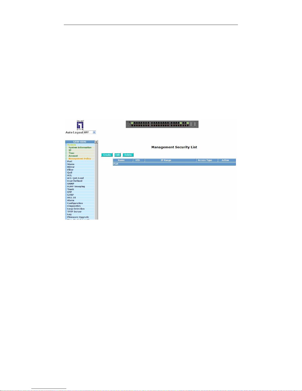
Through the management security configuration, the manager can do the
strict setup to control the switch and limit the user to access this switch.
The following rules are offered for the manager to manage the switch:
Rule 1) : When no lists exists, then it will accept all connections.
Accept
-----------------------------------------------------------------------
Rule 2) : When only “accept lists” exist, then it will deny all connections,
excluding the connection inside of the accepting range.
Accept
Deny Accept Deny Accept
-----------------------------------------------------------------------
Rule 3) : When only “deny lists” exist, then it will deny all connections.
Deny Accept Deny
Accept
Deny
-----------------------------------------------------------------------
Rule 4) : When both “accept and deny” lists exist, then it will deny all
connections, excluding the connection inside of the accepting range.
Accept
Deny Deny Deny Accept
-----------------------------------------------------------------------
Rule 5) : When both “accept and deny” lists exist, then it will deny all
connections, excluding the connection inside of the accepting range and NOT
inside of the denying range at the same time.
Accept
Deny
Deny| Acc | Deny | Acc | Deny
----------------------------------------------------------------------
Accept
Page 49
User Manual
43
Function name:
Management Security Configuration
Function description:
The switch offers Management Security Configuration function. With this
function, the manager can easily control the mode that the user connects to
the switch. According to the mode, users can be classified into two types:
Those who are able to connect to the switch (Accept) and those who are
unable to connect to the switch (Deny). Some restrictions also can be placed
on the mode that the user connect to the switch, for example, we can decide
that which VLAN VID is able to be accepted or denied by the switch, the IP
range of the user could be accepted or denied by the switch, the port that the
user is allowed or not allowed to connect with the switch, or the way of
controlling and connecting to the switch via Http, Telnet or SNMP.
Fig. 3-7
Parameter description:
Name:
A name is composed of any letter (A-Z, a-z) and digit (0-9) with maximal
8 characters.
VID:
The switch supports two kinds of options for managed valid VLAN VID,
including “Any” and “Custom”. Default is “Any”. When you choose
“Custom”, you can fill in VID number. The valid VID range is 1~4094.
Page 50

User Manual
44
IP Range:
The switch supports two kinds of options for managed valid IP Range,
including “Any” and “Custom”. Default is “Any”. In case that” Custom”
had been chosen, you can assigned effective IP range. The valid range
is 0.0.0.0~255.255.255.255.
Access Type:
The switch supports two kinds of options for managed valid Access Type,
including “Any” and “Custom”. Default is “Any”. “Http”, “Telnet” and
“SNMP” are three ways for the access and managing the switch in case
that” Custom” had been chosen.
Action:
The switch supports two kinds of options for managed valid Action Type,
including “Deny” and “Accept”. Default is “Deny”. When you choose
“Deny” action, you will be restricted and refused to manage the switch
due to the “Access Type” you choose. However, while you select
“Accept” action, you will have the authority to manage the switch.
Port:
The switch supports two kinds of options for managed valid Port Range,
including “Any” and “Custom”. Default is “Any”. You can select the ports
that you would like them to be worked and restricted in the management
security configuration if “Custom” had been chosen.
Create:
A new entry of Management Security Configuration can be created after
the parameters as mentioned above had been setup and then press
<Create> button.
Edit:
The existed entry also can be modified by pressing <Edit> button.
Delete:
Remove the existed entry of Management Security Configuration from
the management security table.
Page 51
User Manual
45
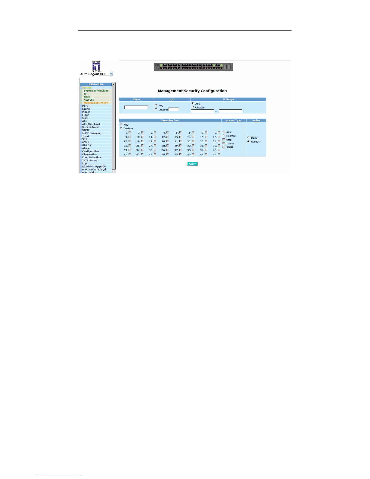
After “Create” or “Edit” button is clicked, the management screen will be
shown(See Fig. 3-8).
Fig. 3-8
Parameter description:
Name:
A name is composed of any letter (A-Z, a-z) and digit (0-9) with maximal
8 characters.
VID:
The switch supports two kinds of options for managed valid VLAN VID,
including “Any” and “Custom”. Default is “Any”. When you choose
“Custom”, you can fill in VID number. The valid VID range is 1~4094.
IP Range:
The switch supports two kinds of options for managed valid IP Range,
including “Any” and “Custom”. Default is “Any”. In case that” Custom”
had been chosen, you can assigned effective IP range. The valid range
is 0.0.0.0~255.255.255.255.
Incoming Port:
The switch supports two kinds of options for managed valid Port Range,
including “Any” and “Custom”. Default is “Any”. You can select the ports
that you would like them to be worked and restricted in the management
security configuration if “Custom” had been chosen.
Access Type:
The switch supports two kinds of options for managed valid Access Type,
including “Any” and “Custom”. Default is “Any”. “Http”, “Telnet” and
“SNMP” are three ways for the access and managing the switch in case
that” Custom” had been chosen.
Page 52

User Manual
46
Action:
The switch supports two kinds of options for managed valid Action Type,
including “Deny” and “Accept”. Default is “Deny”. When you choose
“Deny” action, you will be restricted and refused to manage the switch
due to the “Access Type” you choose. However, while you select
“Accept” action, you will have the authority to manage the switch.
Page 53
User Manual
47
3-2. Port Configuration
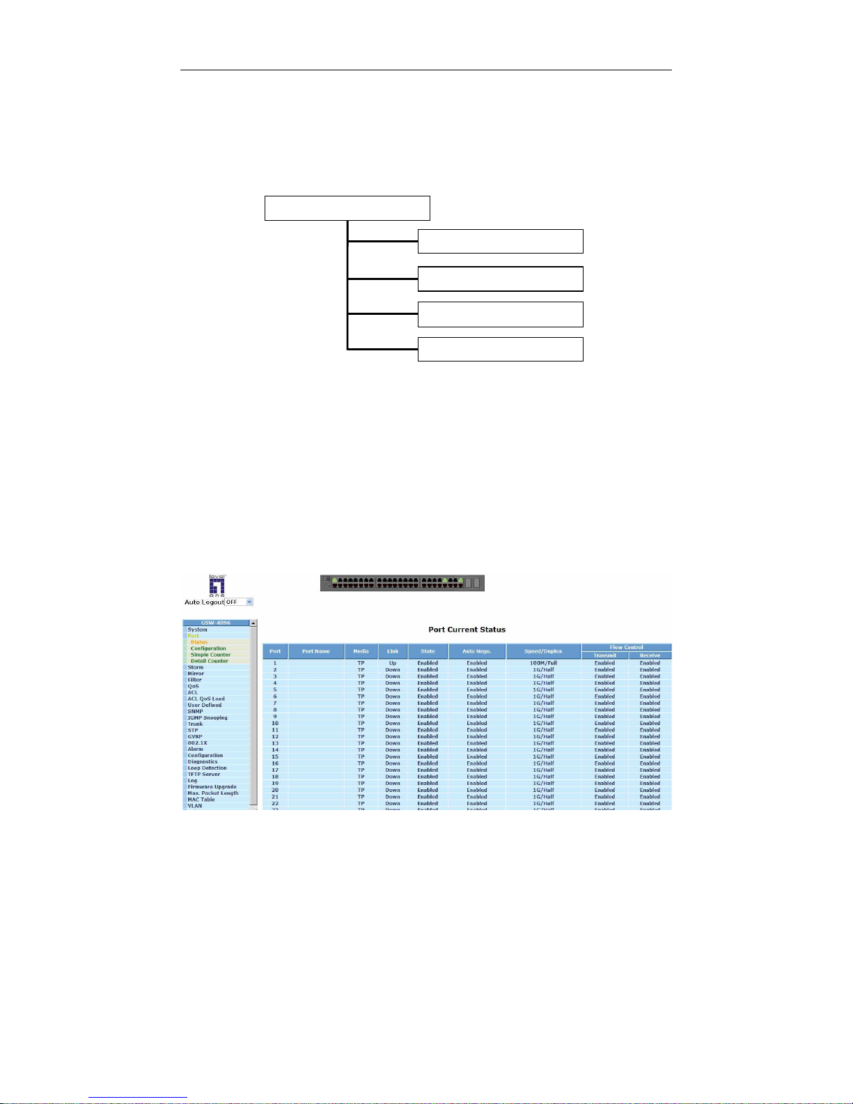
Four functions, including Port Status, Port Configuration, Simple Counter and
Detail Counter are contained in this function folder for port monitor and
management. Each of them will be described in detail orderly in the following
sections.
3-2-1.Port Status
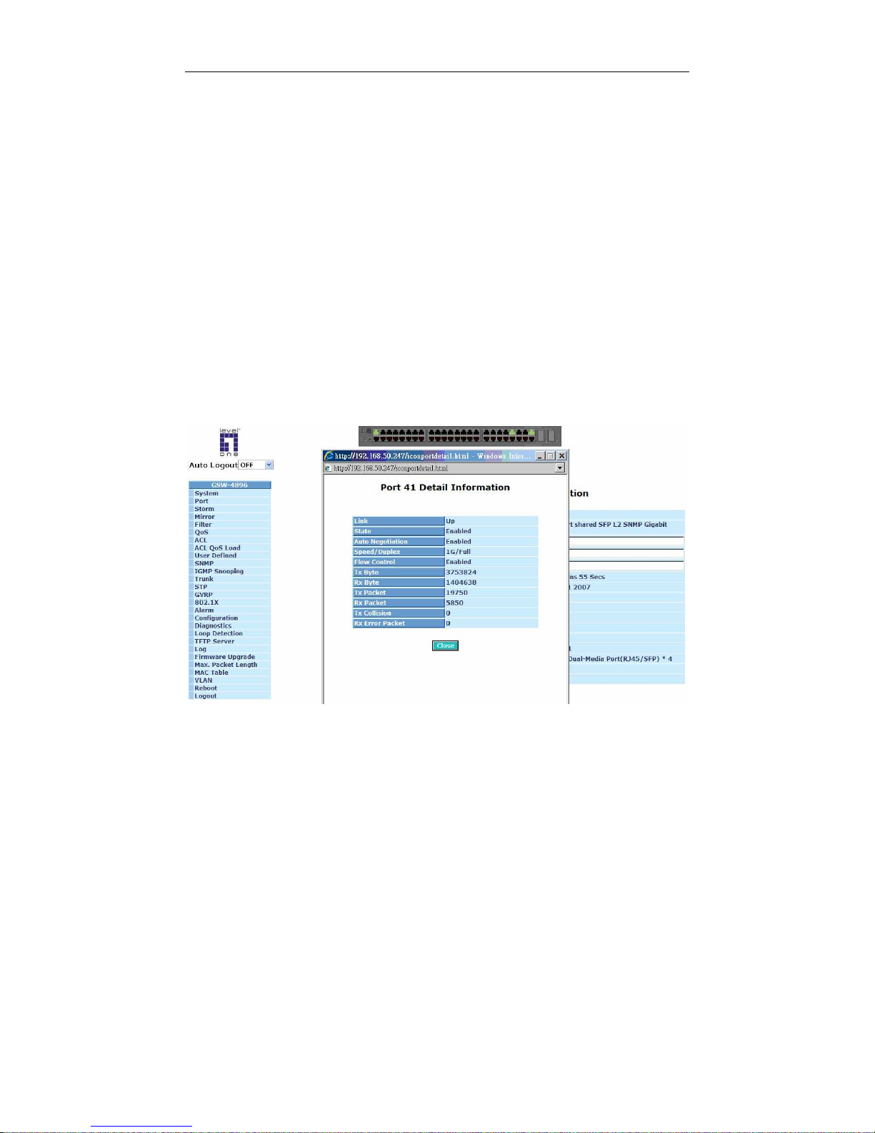
The function Port Status gathers the information of all ports’ current status
and reports it by the order of port number, link status, port state, Auto-Negotiation
status, speed/duplex and flow control. If more detailed port information is needed,
the small switch interface in the top of the page is clickable, and detailed port
information will be shown after a certain port of the small switch interface is clicked
(See Fig. 3-10). Besides, An extra media type information for the module ports 23
and 24 is also offered (See Fig. 3-11). The further port information can be ret
Fig. 3-9
Status
Configuration
Simple
Co
unter
Detail Counte
r
Port
Configuration
Page 54

User Manual
48
FUNCTION NAME:
PORT STATUS
FUNCTION DESCRIPTION:
REPORT THE LATEST UPDATED STATUS OF ALL PORTS IN THIS
SWITCH. WHEN ANY ONE OF THE PORTS IN THE SWITCH CHANGES ITS
PARAMETER DISPLAYED IN THE PAGE, IT WILL BE AUTOMATICALLY
REFRESHED THE PORT CURRENT STATUS ABOUT EVERY 5 SECONDS.
PARAMETER DESCRIPTION:
Port:
Display the port number. The number is 1 - 48.
Port Name:
Display the port name.
Media:
Show the media type adopted in all ports. Port 45 to Port 48 are optional
modules, which support either fiber or UTP media with either Gigabit
Ethernet (1000Mbps) or 10/100Mbps Fast Ethernet port. They may have
different media types and speed. Especially, fiber port has comprehensive
types of connector, distance, fiber mode and so on. The switch describes
the module ports with the following page.
Link:
Show that if the link on the port is active or not. If the link is connected to
a working-well device, the Link will show the link “Up”; otherwise, it will
show “Down”. This is determined by the hardware on both devices of the
connection.
No default value.
State:
Show that the communication function of the port is “Enabled” or
“Disabled”. When it is enabled, traffic can be transmitted and received via
this port. When it is disabled, no traffic can be transferred through this
port. Port State is configured by user.
Default: Enabled.
Auto Negotiation:
Show the exchange mode of Ethernet MAC. There are two modes
supported in the switch. They are auto-negotiation mode “Enabled” and
forced mode “Disabled”. When in “Enabled” mode, this function will
automatically negotiate by hardware itself and exchange each other the
capability of speed and duplex mode with other site which is linked, and
comes out the best communication way. When in “Disabled” mode, both
parties must have the same setting of speed and duplex, otherwise, both
of them will not be linked. In this case, the link result is “Down”.
Page 55
User Manual
49
Default: Enabled
Speed / Duplex Mode:
Display the speed and duplex of all port. There are three speeds 10Mbps,
100Mbps and 1000Mbps supported for TP media, and the duplex
supported is half duplex and full duplex. If the media is 1Gbps fiber, it is
1000Mbps supported only. The status of speed/duplex mode is
determined by 1) the negotiation of both local port and link partner in
“Auto Speed” mode or 2) user setting in “Force” mode. The local port has
to be preset its capability.
Default: None, depends on the result of the negotiation.
Flow Control:
Show each port’s flow control status.
There are two types of flow control in Ethernet, Backpressure for halfduplex operation and Pause flow control (IEEE802.3x) for full-duplex
operation. The switch supports both of them.
Default: Disabled
Fig. 3-10
Parameter description:
Link:
Show that if the link on the port is active or not. If the link is connected to
a working-well device, the Link will show the link “Up”; otherwise, it will
show “Down”. This is determined by the hardware on both devices of the
Page 56

User Manual
50
connection.
No default value.
State:
Show that the communication function of the port is “Enabled” or
“Disabled”. When it is enabled, traffic can be transmitted and received via
this port. When it is disabled, no traffic can be transferred through this
port. Port State is configured by user.
Default: Enabled.
Auto Negotiation:
Show the exchange mode of Ethernet MAC. There are two modes
supported in the switch. They are auto-negotiation mode “Enabled” and
forced mode “Disabled”. When in “Enabled” mode, this function will
automatically negotiate by hardware itself and exchange each other the
capability of speed and duplex mode with other site which is linked, and
comes out the best communication way. When in “Disabled” mode, both
parties must have the same setting of speed and duplex, otherwise, both
of them will not be linked. In this case, the link result is “Down”.
Default: Enabled
Speed / Duplex Mode:
Display the speed and duplex of all port. There are three speeds 10Mbps,
100Mbps and 1000Mbps supported for TP media, and the duplex
supported is half duplex and full duplex. If the media is 1Gbps fiber, it is
1000Mbps supported only. The status of speed/duplex mode is
determined by 1) the negotiation of both local port and link partner in
“Auto Speed” mode or 2) user setting in “Force” mode. The local port has
to be preset its capability.
Default: None, depends on the result of the negotiation.
Flow Control:
Show each port’s flow control status.
There are two types of flow control in Ethernet, Backpressure for halfduplex operation and Pause flow control (IEEE802.3x) for full-duplex
operation. The switch supports both of them.
Default: Disabled
Tx Byte:
Transmitted bytes on this port.
Rx Byte:
Received bytes on this port.
Tx Packet:
Transmitted packets on this port.
Rx Packet:
Received packets on this port.
Page 57

User Manual
51
Tx Collision:
Number of collisions transmitting frames experienced.
Rx Error Packet:
Number of fault packets received.
Page 58
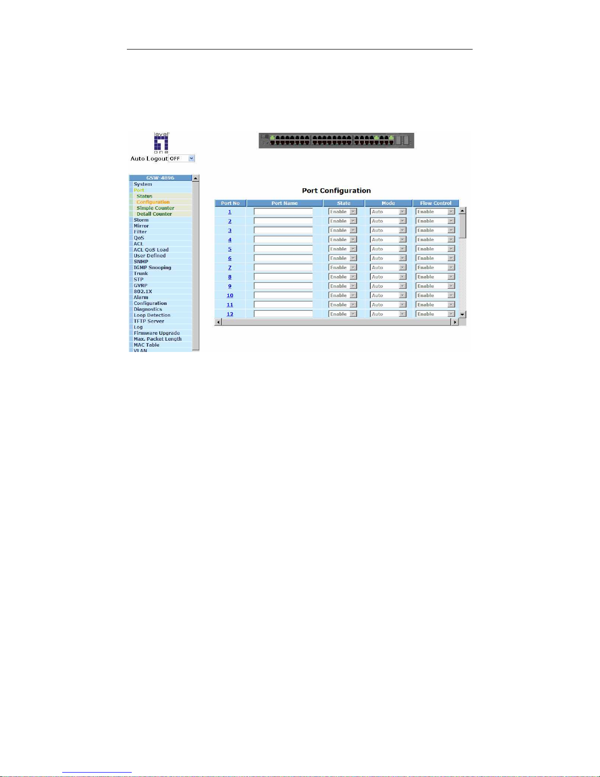
User Manual
52
3-2-2. Port Configuration
Port Configuration is applied to change the setting of each port. In this
configuration function, you can set/reset the following functions. The Port No. is
clickable. After it is clicked, a pop-up window including the same configuration table
for a specific port will be shown. All of them are described in detail below.
T
Fig. 3-11
T
Function name:
T
Port Configuration
T
Function description:
T
It is used to set each port’s operation mode. The switch supports 3 parameters
for each port. They are state, mode and flow control.
T
Parameter description:
Port No:
Display the port number. The number is 1 - 48.
Port Name:
Display the port name. To create a new port name, you may click the port
number first, input the name you want into “Port Name” field, then click
<Apply> button.
State:
Set the communication capability of the port is Enabled or Disabled.
When enabled, traffic can be transmitted and received via this port.
When disabled, the port is blocked and no traffic can be transferred
Page 59

User Manual
53
through this port. Port State is configurable by the user. There are only
two states “Enable” and “Disable” able to choose. If you set a port’s state
“Disable”, then that port is prohibited to pass any traffic, even it looks
Link up.
Default: Enable.
Mode:
Set the speed and duplex of the port. In speed, if the media is 1Gbps
fiber, it is always 1000Mbps and the duplex is full only. If the media is TP,
the Speed/Duplex is comprised of the combination of speed mode,
10/100/1000Mbps, and duplex mode, full duplex and half duplex. The
following table summarized the function the media supports.
Media type NWay Speed Duplex
1000M TP ON/OFF 10/100/1000M Full for all, Half for 10/100
1000M Fiber ON/OFF 1000M Full
In Auto-negotiation mode, no default value. In Forced mode, default
value depends on your setting.
Flow Control:
There are two modes to choose in flow control, including Enable and
Disable. If flow control is set Enable, both parties can send PAUSE frame
to the transmitting device(s) if the receiving port is too busy to handle.
When it is set Disable, there will be no flow control in the port. It drops
the packet if too much to handle.
Default: Enable.
Page 60
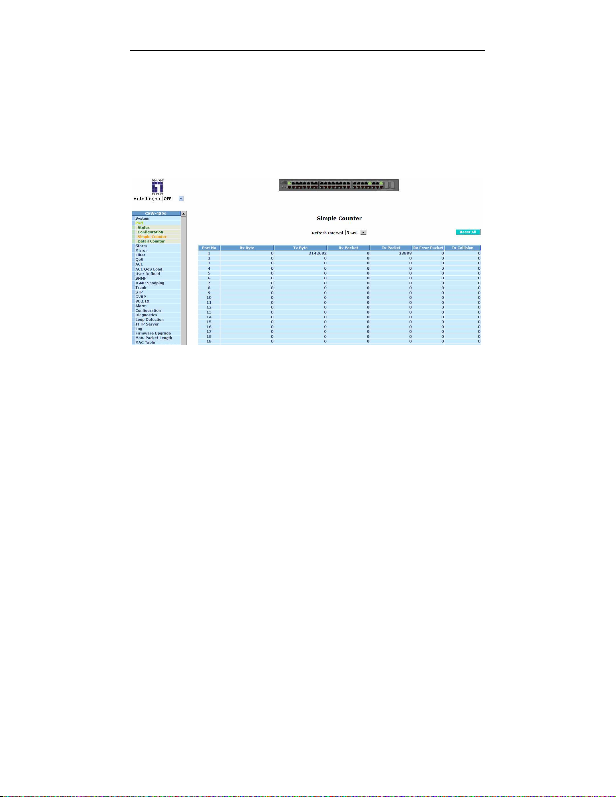
User Manual
54
3-2-3. Simple Counter
The function of Simple Counter collects any information and provides the
counting about the traffic of the port, no matter the packet is good or bad.
In the Fig. 3-12, the window can show all ports’ counter information at the
same time. Each data field has 20-digit long. If the counting is overflow, the counter
will be reset and restart counting. The data is updated every time interval defined by
the user. The valid range is 3 to 10 seconds. The Refresh Interval is used to set the
update frequency. Default update time is 3 seconds.
Fig. 3-12
Function name:
Simple Counter
Function description:
Display the summary counting of each port’s traffic, including Tx Byte, Rx Byte,
Tx Packet, Rx Packet, Tx Collision and Rx Error Packet.
Parameters description:
Rx Byte:
Total received bytes.
Tx Byte:
Total transmitted bytes.
Rx Packet:
The counting number of the packet received.
Tx Packet:
The counting number of the packet transmitted.
Rx Error Packet:
Number of bad packets received.
Page 61
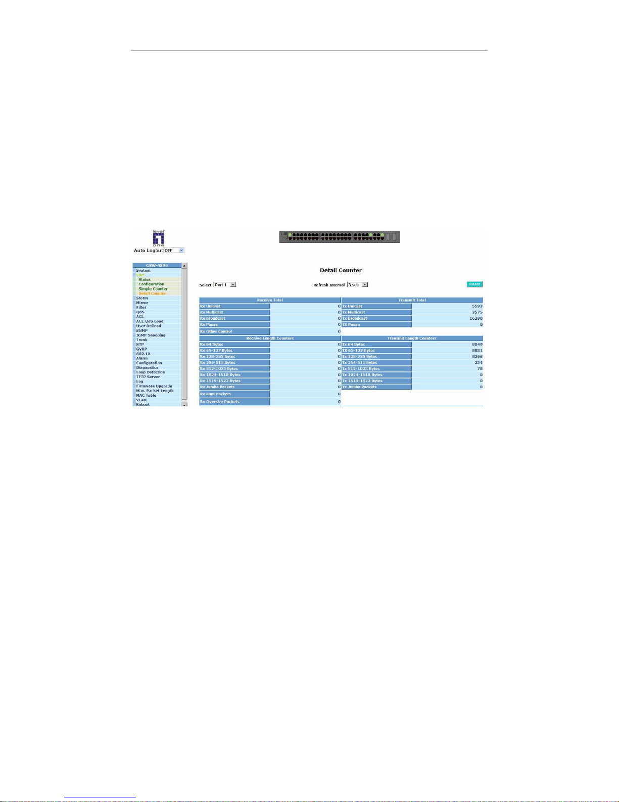
User Manual
55
Tx Collision:
Number of collisions transmitting frames experienced.
3-2-4. Detail Counter
The function of Detail Counter collects any information and provides the
counting about the traffic of the port, no matter the packet is good or bad.
In the Fig. 3-13, the window can show only one port counter information at
the same time. To see another port’s counter, you have to pull down the list of
Select, then you will see the figures displayed about the port you had chosen.
Each data field has 20-digit long. If the counting is overflow, the counter will
be reset and restart counting. The data is updated every time interval defined by the
user. The valid range is 3 to 10 seconds. The Refresh Interval is used to set the
update frequency. Default update time is 3 seconds.
Fig. 3-13
Function name:
Detail Counter
Function description:
Display the detailed counting number of each port’s traffic. In the Fig. 3-14, the
window can show all counter information of each port at one time.
Parameter description:
Rx Unicast:
Show the counting number of the received unicast packet.
Rx Multicast:
Show the counting number of the received multicast packet.
Rx Broadcast:
Show the counting number of the received broadcast packet.
Rx Pause:
Page 62

User Manual
56
Rx Other Control:
Show the counting number of the received other control packet.
Rx 64 Bytes:
Number of 64-byte frames in good and bad packets received.
Rx 65-127 Bytes:
Number of 65 ~ 126-byte frames in good and bad packets received.
Rx 128-255 Bytes:
Number of 127 ~ 255-byte frames in good and bad packets received.
Rx 256-511 Bytes:
Number of 256 ~ 511-byte frames in good and bad packets received.
Rx 512-1023 Bytes:
Number of 512 ~ 1023-byte frames in good and bad packets received.
Rx 1024-1518 Bytes:
Number of 1024 ~ 1518-byte frames in good and bad packets received.
Rx 1519-1522 Bytes:
Number of 1519 ~ 1522-byte frames in good and bad packets received.
Rx Jumbo Packets:
Number of jumbo packets received.
Rx Runt Packets:
Number of runt packets received.
Rx Oversize Packets:
Number of long frames(according to max_length register) with valid CRC.
Rx CRC:
Number of CRC error packets received.
Rx Code:
Rx Fragments:
Number of short frames (< 64 bytes) with invalid CRC.
Tx Unicast:
Show the counting number of the transmitted unicast packet.
Tx Multicast:
Show the counting number of the transmitted multicast packet.
Tx Broadcast:
Show the counting number of the transmitted broadcast packet.
Tx Pause:
Tx 64 Bytes:
Page 63

User Manual
57
Number of 64-byte frames in good and bad packets transmitted.
Tx 65-127 Bytes:
Number of 65 ~ 126-byte frames in good and bad packets transmitted.
Tx 128-255 Bytes:
Number of 127 ~ 255-byte frames in good and bad packets transmitted.
Tx 256-511 Bytes:
Number of 256 ~ 511-byte frames in good and bad packets transmitted.
Tx 512-1023 Bytes:
Number of 512 ~ 1023-byte frames in good and bad packets transmitted.
Tx 1024-1518 Bytes:
Number of 1024 ~ 1518 frames in good and bad packets transmitted.
Tx 1519-1522 Bytes:
Number of 1519 ~ 1522 frames in good and bad packets transmitted.
Tx Jumbo Packets:
Number of jumbo packets transmitted.
Tx Single Collision:
Number of single collision transmitting frames experienced.
Tx Multiple Collisions:
Number of multiple collisions transmitting frames experienced.
Tx Late Collisions:
Number of late collisions transmitting frames experienced.
Tx Deferred:
Number of frames deferred
Page 64
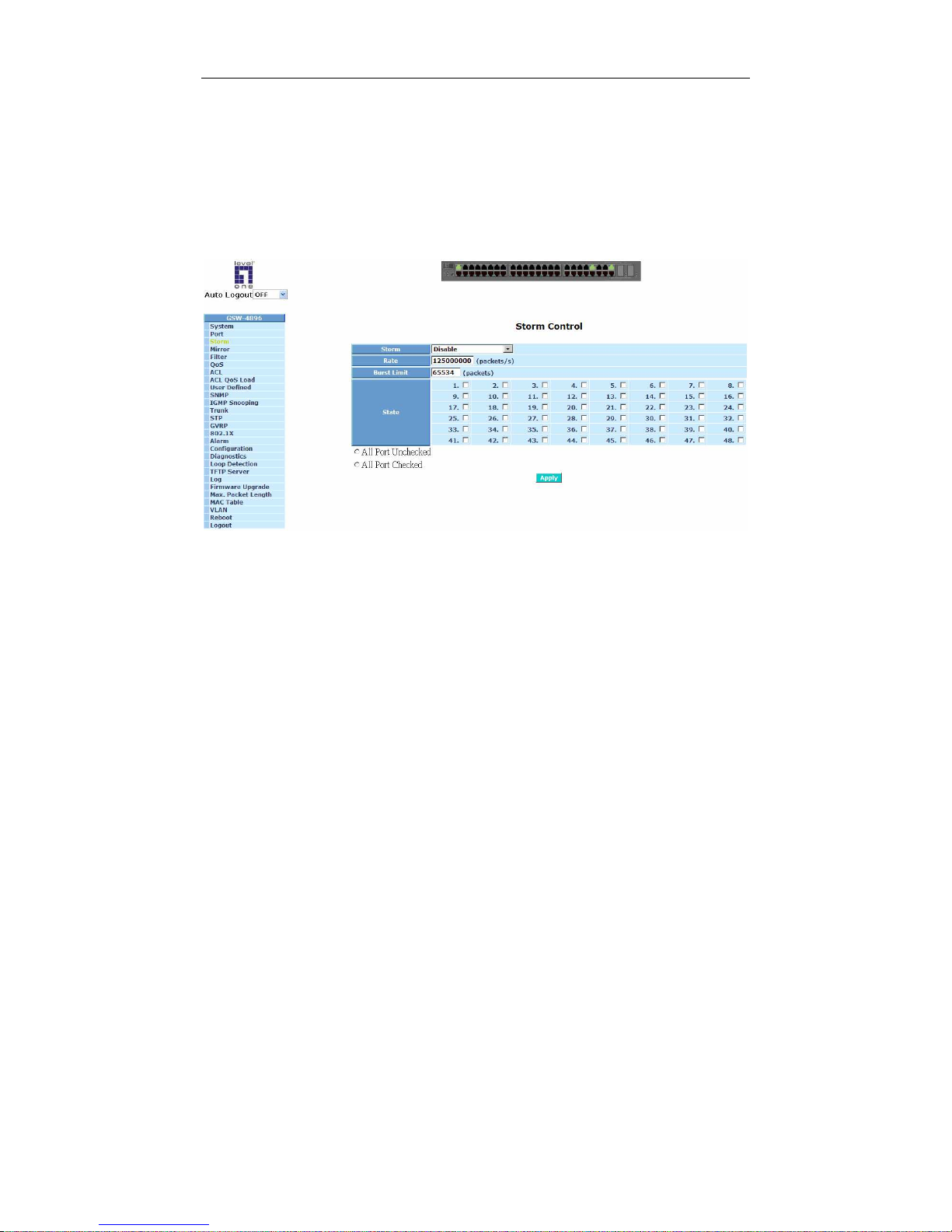
User Manual
58
3-3. Storm
Function name:
Storm Control
Function description:
Storm control function helps limit the broadcast and multicast packets once
over pre-defined threshold, thus prevents from network outrage.
Fig. 3-14
Parameter description:
Storm:
To enable or disable Storm Control function. When the Storm Control is
enable, broadcast storm can be controlled if “Broadcast” is chosen. If
“Broadcast &Multicast” is chosen, broadcast and multicast storm can be
controlled.
Rate:
The rate setting as packets per second for storm control function.
The
minimum value is 238 packets/s.
Burst Limit:
The limitation size for broadcast and multicast packets.
State:
To select ports for Storm Control function.
Page 65
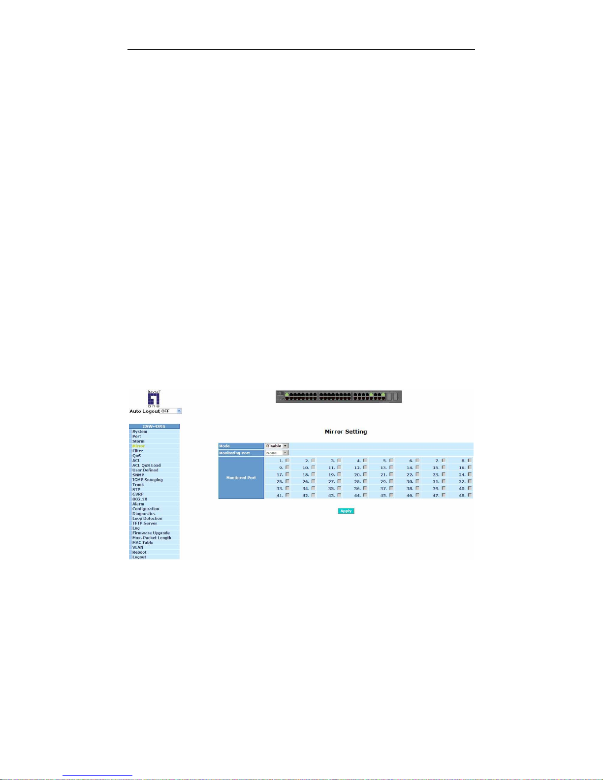
User Manual
59
3-4. Mirror
Function name:
Mirror Configuration
Function description:
Mirror Configuration is to monitor the traffic of the network. For example, we
assume that Port A and Port B are
Monitoring Port and Monitored Port
respectively, thus, the traffic received by Port B will be copied to Port A for
monitoring.
Note:
While configuring mirror function, please do not set a port as sniffer port and
aggregated port at the same time, otherwise, it would cause problems.
Parameter description:
Mode:
Used for the activation or de-activation of Port Mirror function. Default is
disable.
Monitoring Port:
Set up the port for monitoring. Valid port is Port 1~48 and default is
Port 1.
Monitored Port:
Set up the port for being monitored. Just tick the check box (
)
beside
the port x and valid port is Port 1~48.
T
Fig. 3-15
Page 66
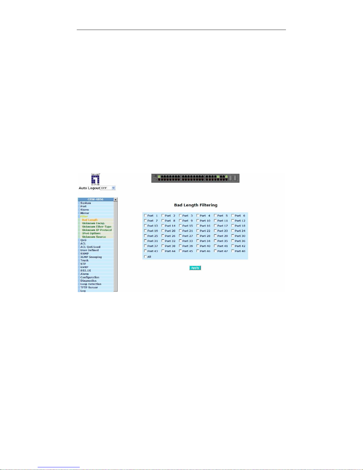
User Manual
60
TTT
3-5. Filter
Filter function is used to drop specific packets to maintain a clean network
environment. Filtering rules can be set by the following items:
1. Bad Length
2. Unknown Encapsulation
3. Unknown Ether-Type
4. Unknown IP Protocol
5. IPv4 Options
6. Unknown Source
3-5-1. Bad Length
Function name:
Bad Length Filtering
Function description:
Whenever number of times an attempt was made to transmit a packet larger
than the specified maximum allowed, the packet would be filtered.
T
Fig. 3-16
Page 67
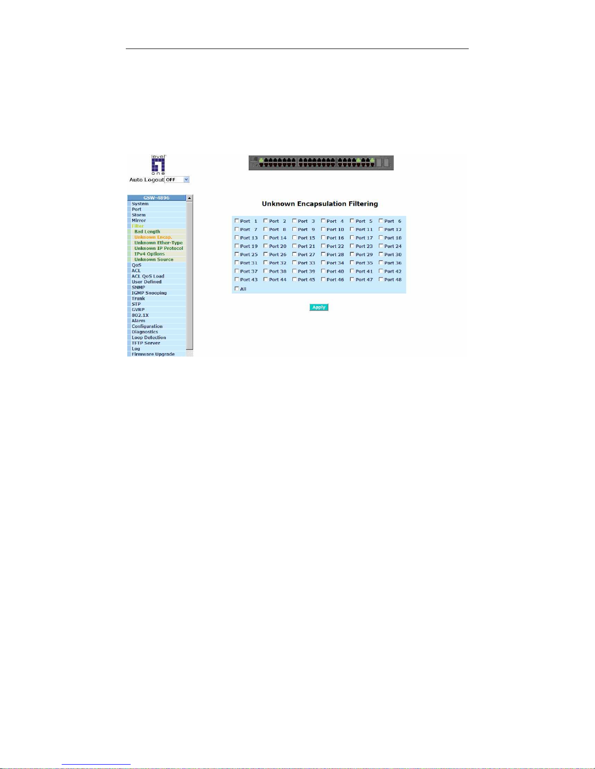
User Manual
61
TT
3-5-2. Unknown Encap.
Function name:
Unknown Encapsulation Filtering
Function description:
If a received packet’s encapsulation is neither Ethernet V2 nor SNAP, then
the packet would be discarded.
Fig. 3-17
Page 68
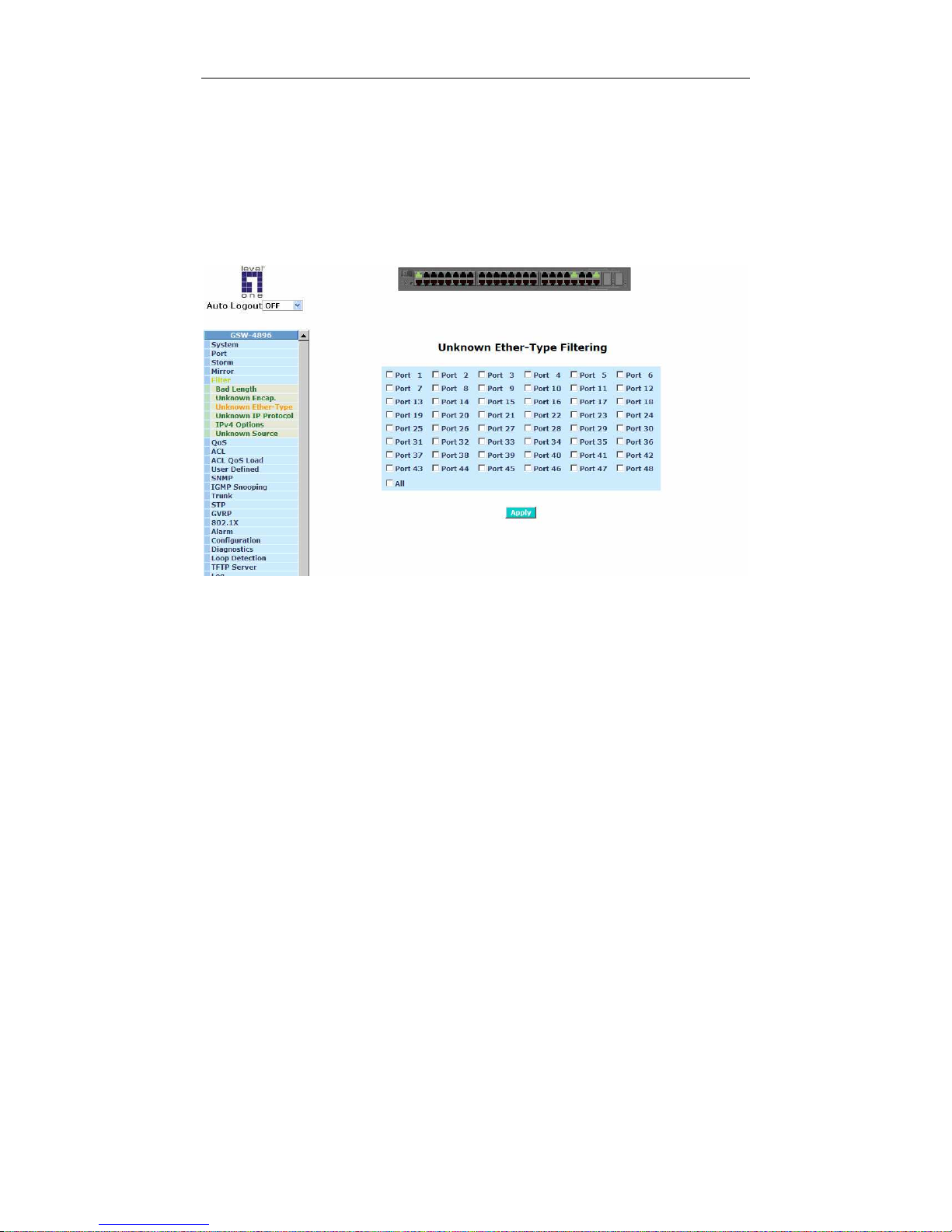
User Manual
62
3-5-3. Unknown Ether-Type
Function name:
Unknown Ether-Type Filtering
Function description:
If a received packet’s Ethernet type is not IPv4, IPv6, ARP or RARP, then the
packet would be filtered.
Fig. 3-18
Page 69
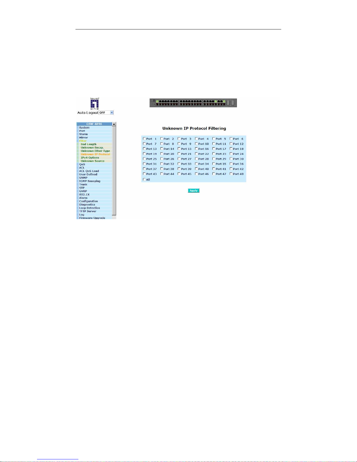
User Manual
63
3-5-4. Unknown IP Protocol
Function name:
Unknown IP Protocol Filtering
Function description:
Whenever unknown IP Protocol found, the packet would be filtered. The
default allowed IP Protocol types are ICMP, IGMP, TCP, and UDP.
Fig. 3-19
Page 70
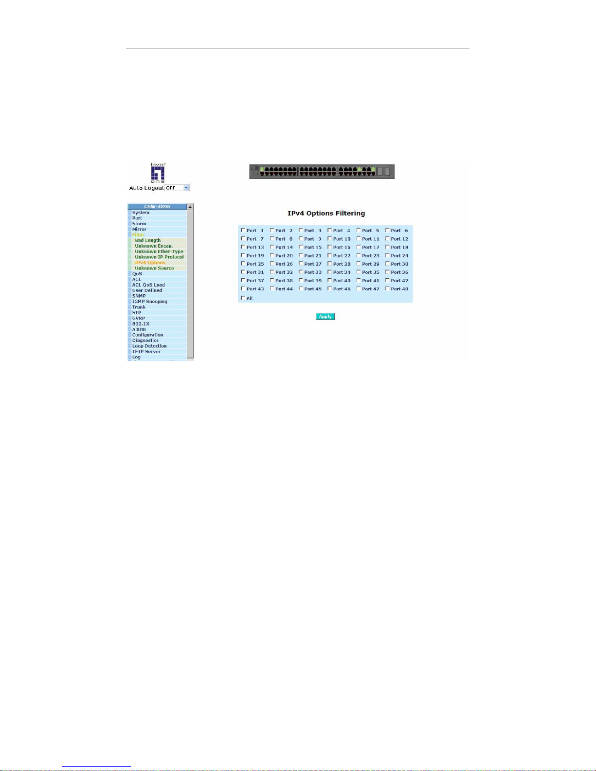
User Manual
64
3-5-5. IPv4 Options
Function name:
IPv4 Options Filtering
Function description:
Whenever IPv4 packet is found with options field included, the packet would
be filtered.
Fig. 3-20
Page 71
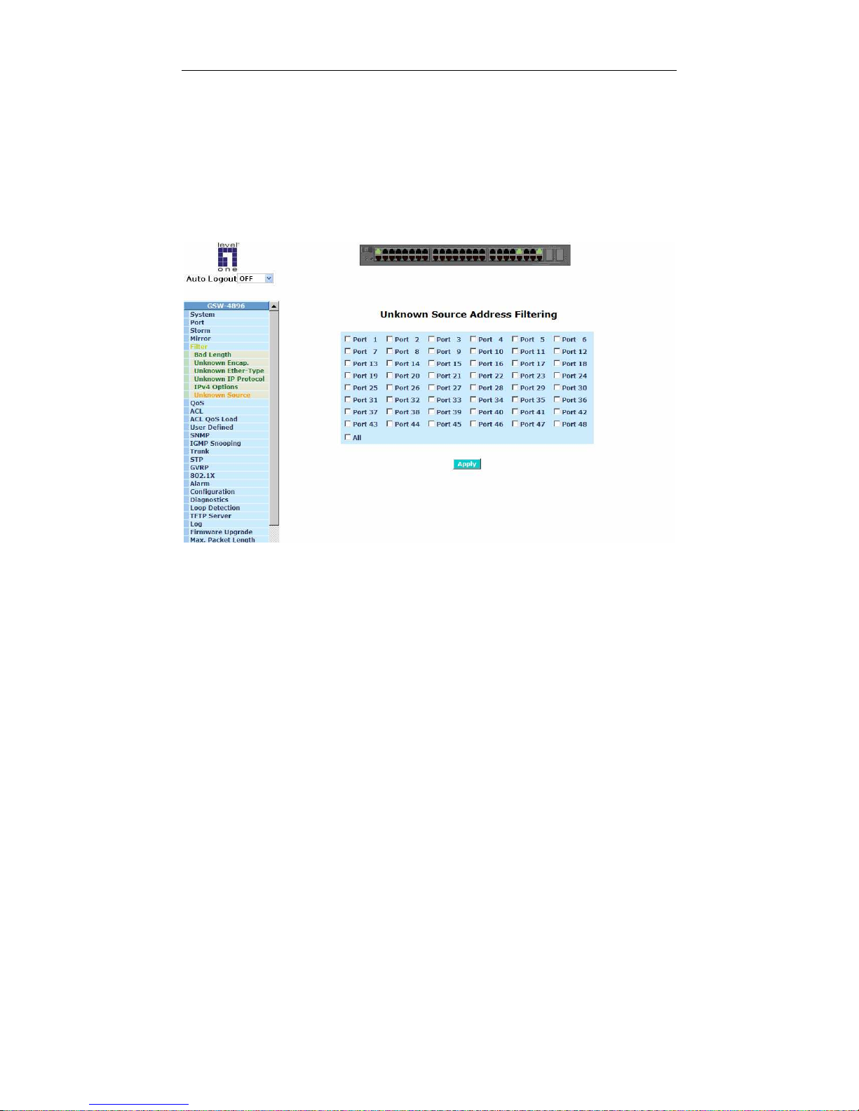
User Manual
65
3-5-6. Unknown Source
Function name:
Unknown Source Address Filtering
Function description:
A received packet whose source MAC address not included in MAC address
table would be filtered.
Fig. 3-21
Page 72
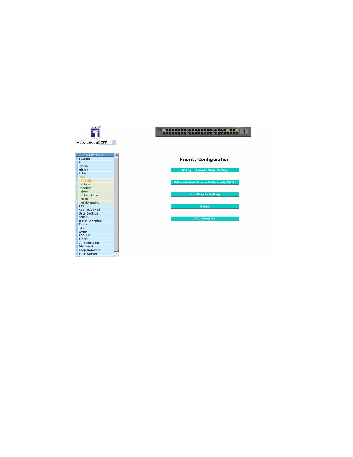
User Manual
66
3-6. QoS(Quality of Service) Configuration
The
switch
offers seven powerful QoS functions. Moreover, Priority
Configuration function set for each port by different precedence is also provided.
QoS enables you to provide better service to certain flows. This is done by either
raising the priority of a flow or limiting the priority of another flow. When using congestionmanagement tools, you try to raise the priority of a flow by queuing and servicing queues in
different ways. The queue management tool used for congestion avoidance raises priority by
dropping lower-priority flows before higher-priority flows. Policing and shaping provide priority
to a flow by limiting the throughput of other flows. Link efficiency tools limit large flows to
show a preference for small flows.
3-6-1. Priority
Fig. 3-22
Page 73
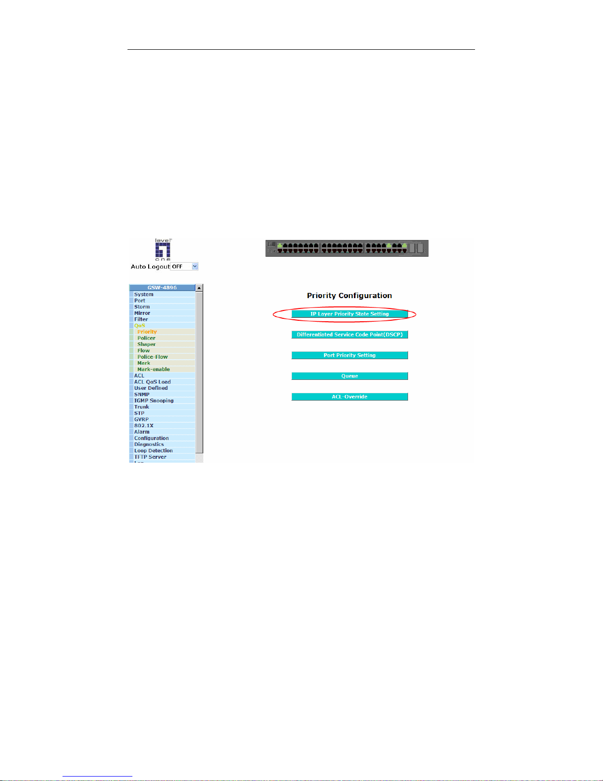
User Manual
67
Function name:
Priority - IP Layer Priority State Setting
Function description:
Set Priority State by IP Layer or Not-IP Layer.
If both Layer 2 (VLAN) and Layer 3 (IP) priority information are available in
the receive packet, the Layer 3 information would take precedence unless
the IP-Ignored of related port is enabled.
Parameter description:
IP-Ignored:
To enable or disable the selection for IP Layer Priority setting. The
default value is Disable as Priority State Setting would depends on IP
Layer.
Fig. 3-23a
Page 74
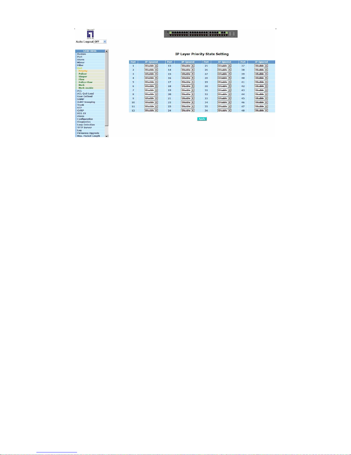
User Manual
68
Fig. 3-23b
Page 75
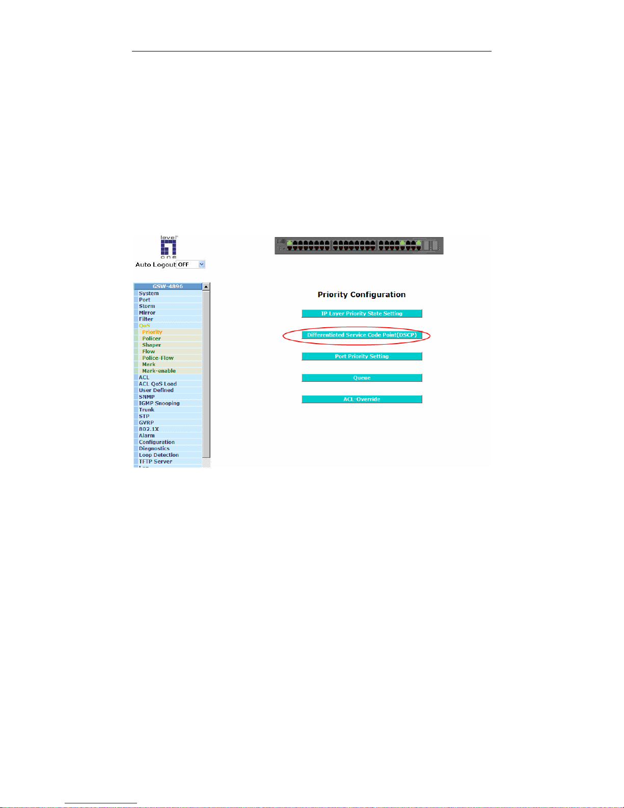
User Manual
69
Function name:
Priority - Differentiated Service Code Point(DSCP)
Function description:
Set Priority State for every DSCP.
IP packets utilize the DSCP field to assign priority. These 64-entry table are
addressed by 6-bit DSCP field from the IP header. This table may be
configured arbitrarily, however, it is recommended that lower-value entries
relate to lower-priority levels.
Parameter description:
Priority: Priority setting range from 0 to 7
Fig. 3-24a
Page 76
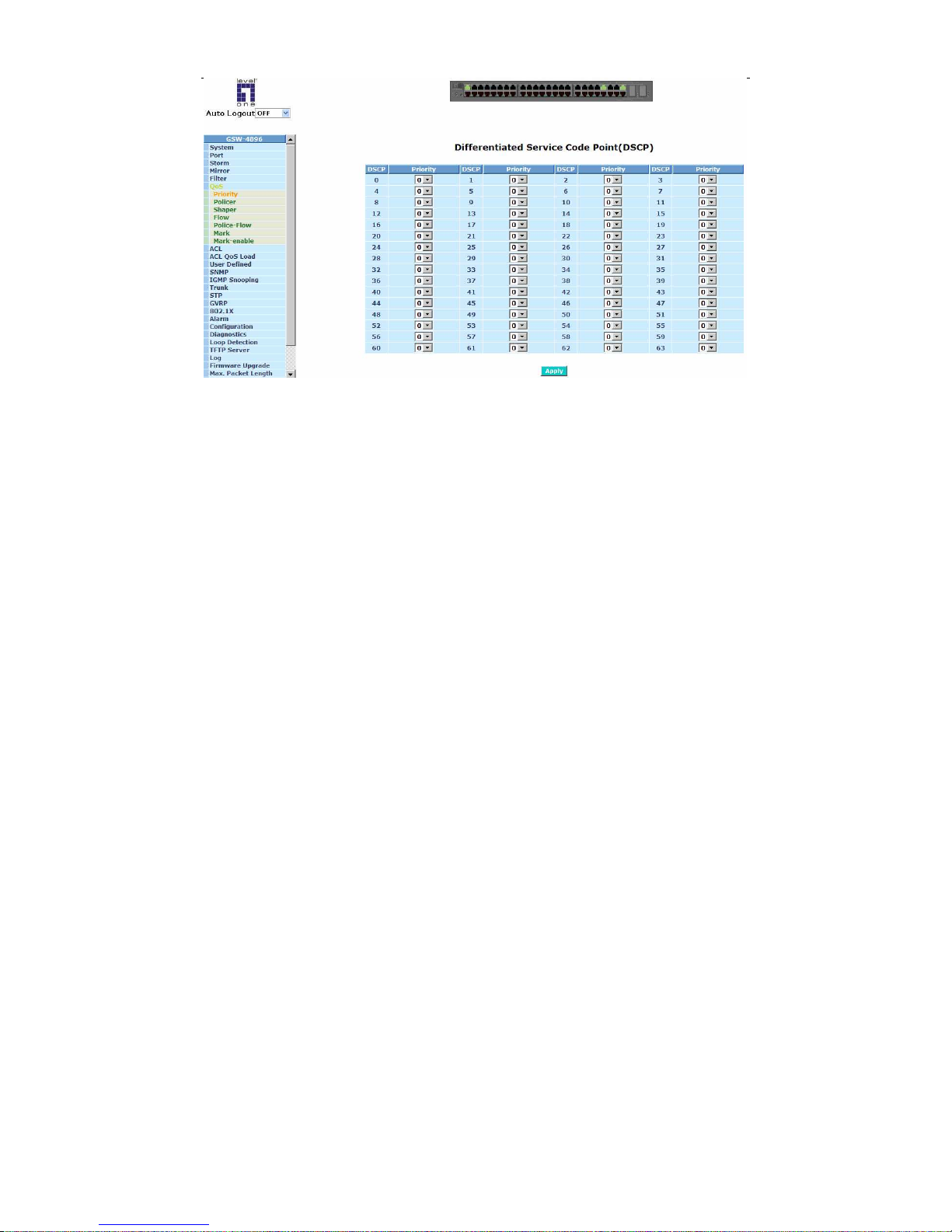
User Manual
70
Fig. 3-24b
Page 77
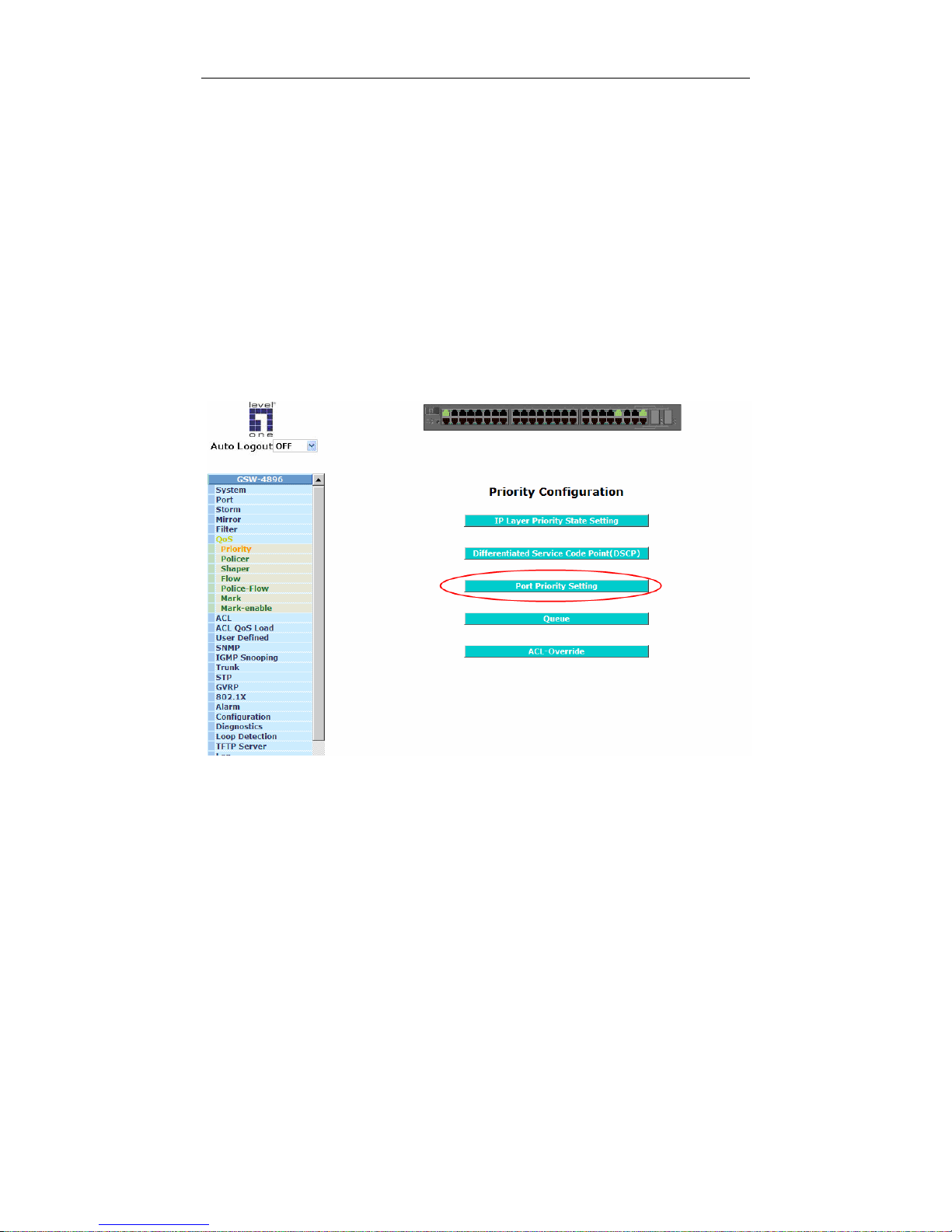
User Manual
71
Function name:
Priority - Port Priority Setting
Function description:
Set Priority State for every port.
Upon reception, each packet is assigned a priority value. The most basic
priority assignment comes from the receive port’s default priority. This default
port priority is used whenever Layer 2 (VLAN) and Layer 3 (IP) priority
information is not available.
Parameter description:
Priority: Priority setting, valid range is from 0 to 7
The lowest possible priority is represented by value 0 while the highest
priority is represented by the value 7.
Fig. 3-25a
Page 78
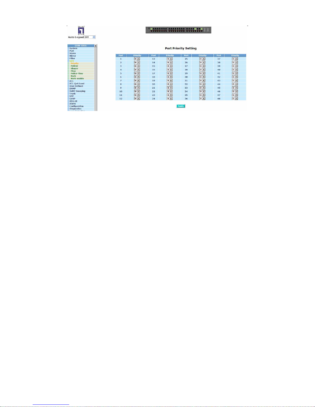
User Manual
72
Fig. 3-25b
Page 79
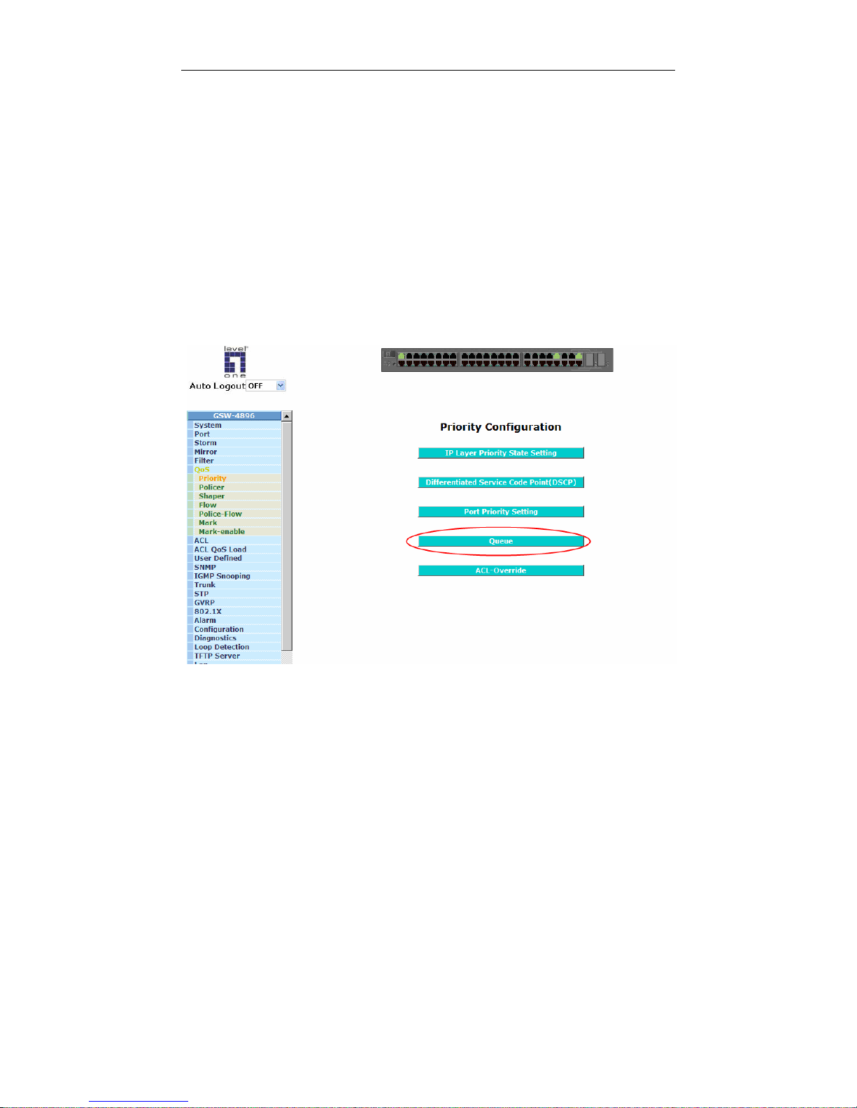
User Manual
73
Function name:
Priority - Shaper Queue
Function description:
Set Shaper Queue number for each Priority.
The device supports 8 levels of internal priority representation. However,
there are 4 queues available for each transmit port. This 8-entry table is used
to map the 8 packet priority to one of the shaper queue.
Parameter description:
Queue: Shaper Queue number, valid value is from 0 to 3.
Queue number zero is the lowest priority queue, while queue number three is
the highest.
Fig. 3-26a
Page 80
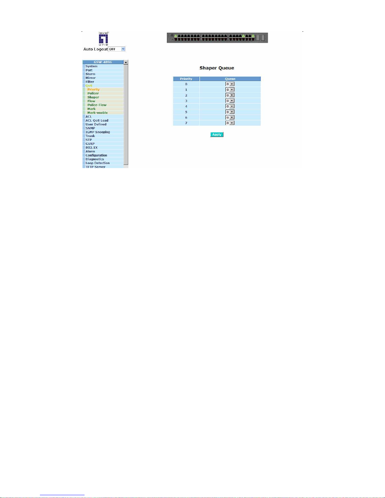
User Manual
74
Fig. 3-26b
Page 81
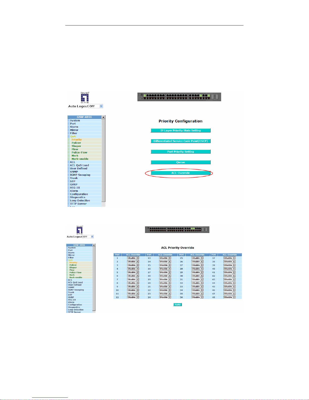
User Manual
75
Function name:
Priority - ACL Priority Override
Function description:
Set whether let ACL rule override the above priority settings.
Parameter description:
ACL-Override: Enable or Disable ACL rule override the above priority settings.
Fig. 3-27a
Fig. 3-27b
Page 82
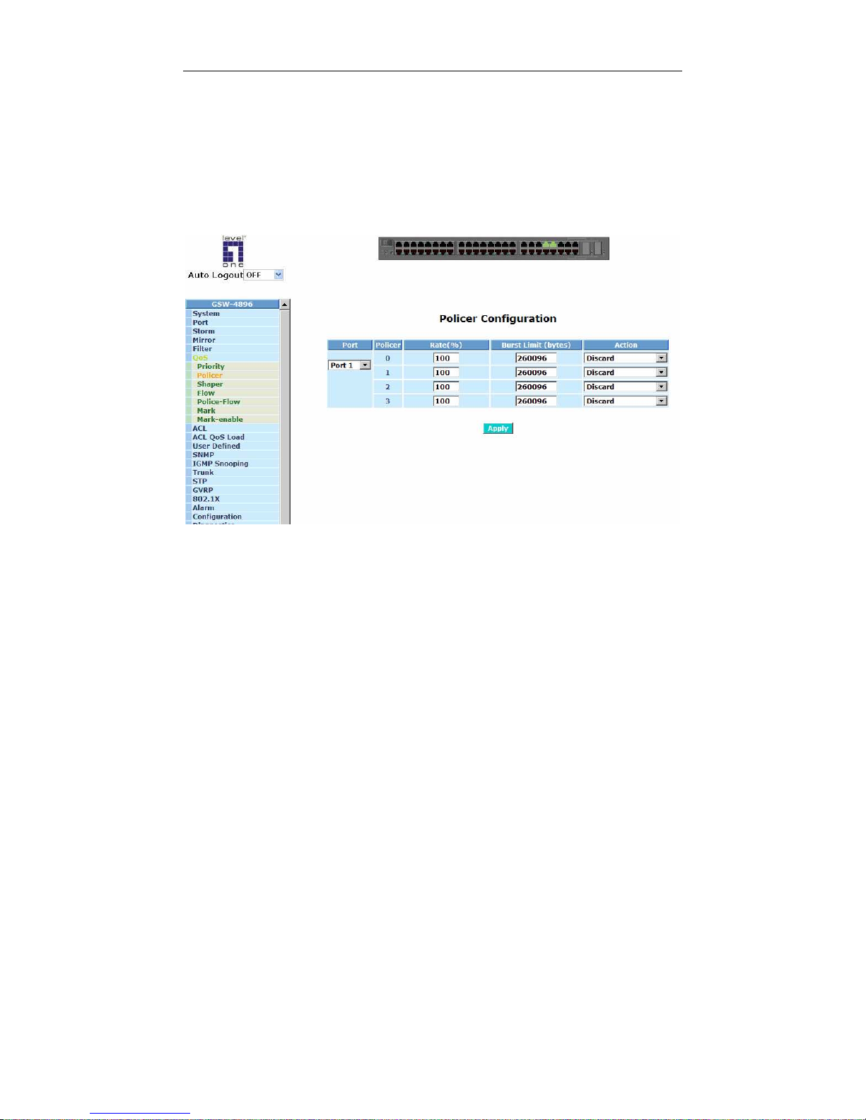
User Manual
76
3-6-2. Policer
Function name:
Policer Configuration
Function description:
Policer provides the function to regulate Ingress network traffic flow. Policing
(dropping) may drop some packets to bring a traffic stream into compliance
with a traffic profile specified via policies.
Fig. 3-28
Parameter description:
Port:
For selecting the port number. Each port includes four policers.
Policer:
Policer identifier number.
Rate:
The policing rate for transfer speed.
Burst Limit (bytes):
The limitation of traffic flow
The limit established for a policer defines the maximum duration of outof-profile traffic that is tolerated without penalty.
Action:
Four policing actions are presented: Pass, Demote, Discard-congested,
and Discard.
Page 83
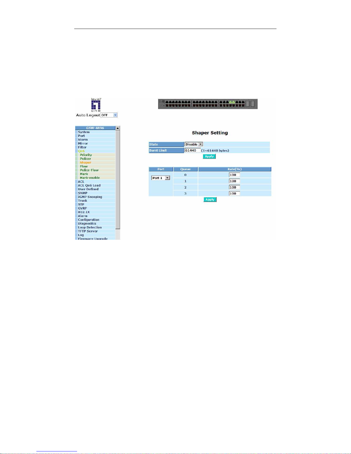
User Manual
77
3-6-3. Shaper
Function name:
Shaper Setting
Function description:
T
The primary purpose of Shaper is to control Egress access to available
bandwidth.
Fig. 3-29
Parameter description:
State:
To enable or disable Shaper function.
Burst Limit:
The limitation of traffic flow, the valid value is from 1 to 61440 bytes.
Port:
For selecting the port number. Every port has four shapers.
Rate:
The shaping rate for transfer speed.
Page 84
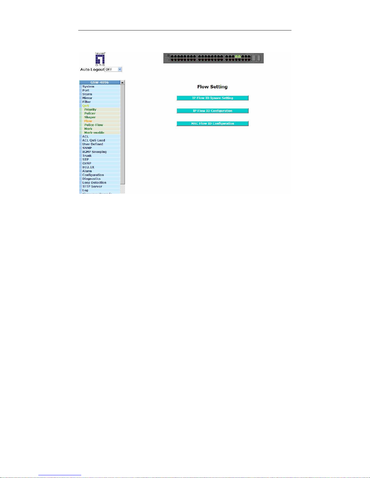
User Manual
78
3-6-4. Flow
Fig. 3-30
Page 85
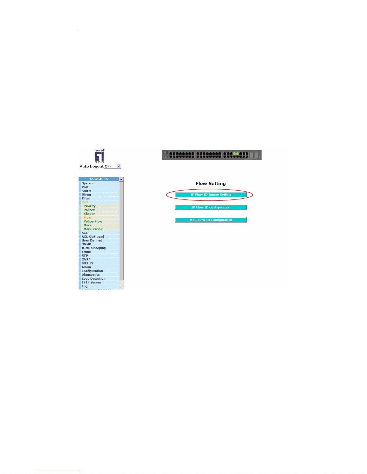
User Manual
79
Function name:
Flow - IP Flow ID Ignore Setting
Function description:
Set Priority State by IP Layer or Not-IP Layer for each port.
Layer 3 priority information is ordinarily used of all IP packets while Layer 2
information is used of all non-IP packets for Flow ID selection. The device
can be configured to always use Layer 2 priority information by enabling the
IP-ignored field of related port.
Parameter description:
IP-Ignored:
To enable or disable the selection for IP Layer Priority setting. The
default value is Disable as IP Flow ID Ignore Setting would depends on
IP Layer.
Fig. 3-31a
Page 86
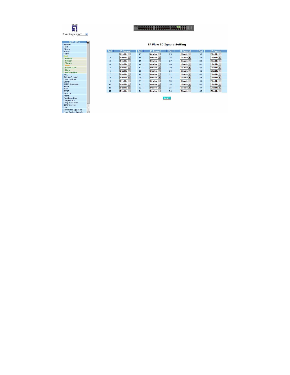
User Manual
80
Fig. 3-31b
Page 87
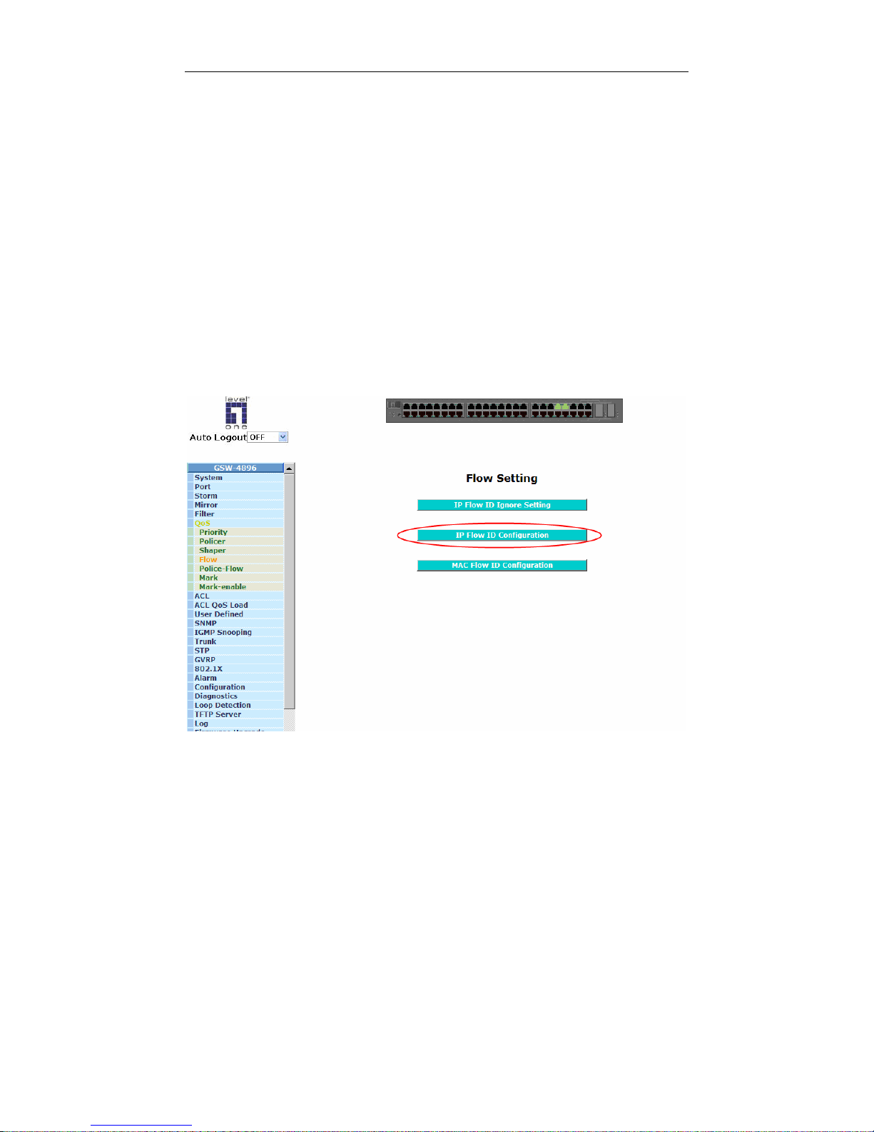
User Manual
81
Function name:
Flow - IP Flow ID Configuration
Function description:
Set IP Flow ID Configuration.
Parameter description:
IP:
IP address for flow
Prefix:
Mask for IP, valid value is from 0 to 32.
Source Flow ID:
Identifier for source flow
set in Police-Flow ID Table.
Destination Flow ID:
Identifier for destination flow set in Police-Flow ID Table.
Fig. 3-32a
Page 88
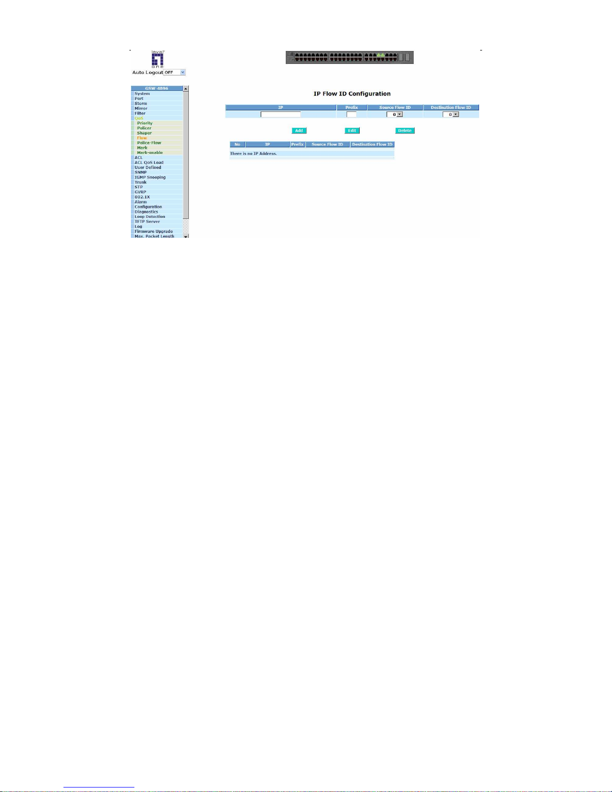
User Manual
82
Fig. 3-32b
Page 89
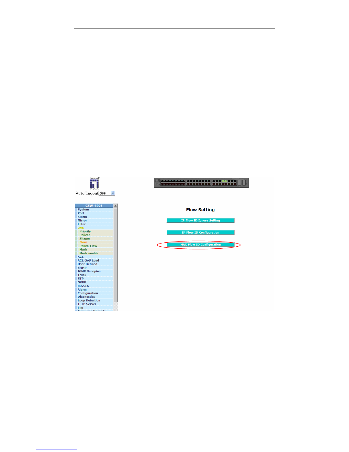
User Manual
83
Function name:
Flow - Static Forwarding MAC
Function description:
Set IP Flow ID Configuration.
Parameter description:
MAC:
MAC address for flow
Port No:
Port identifier number.
Source Flow ID:
Identifier for source flow set in Police-Flow ID Table.
Destination Flow ID:
Identifier for destination flow set in Police-Flow ID Table.
Alias:
Alias for the setting.
Fig. 3-33a
Page 90
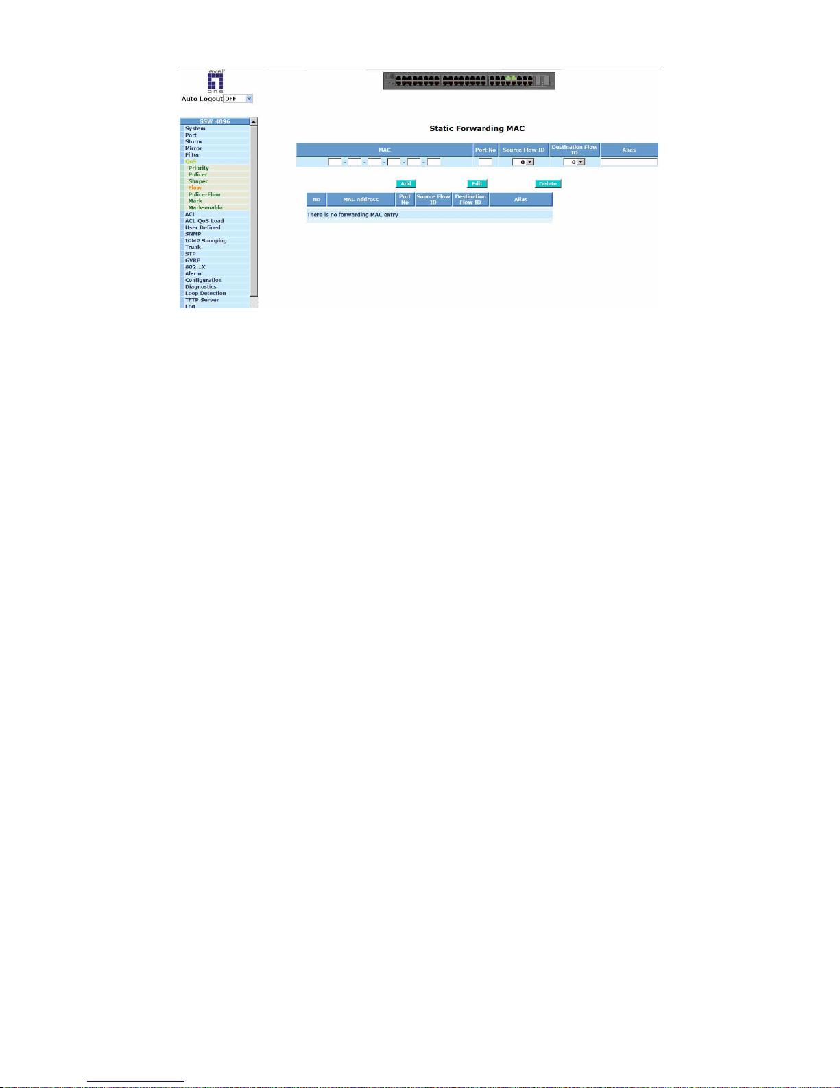
User Manual
84
Fig. 3-33b
Page 91
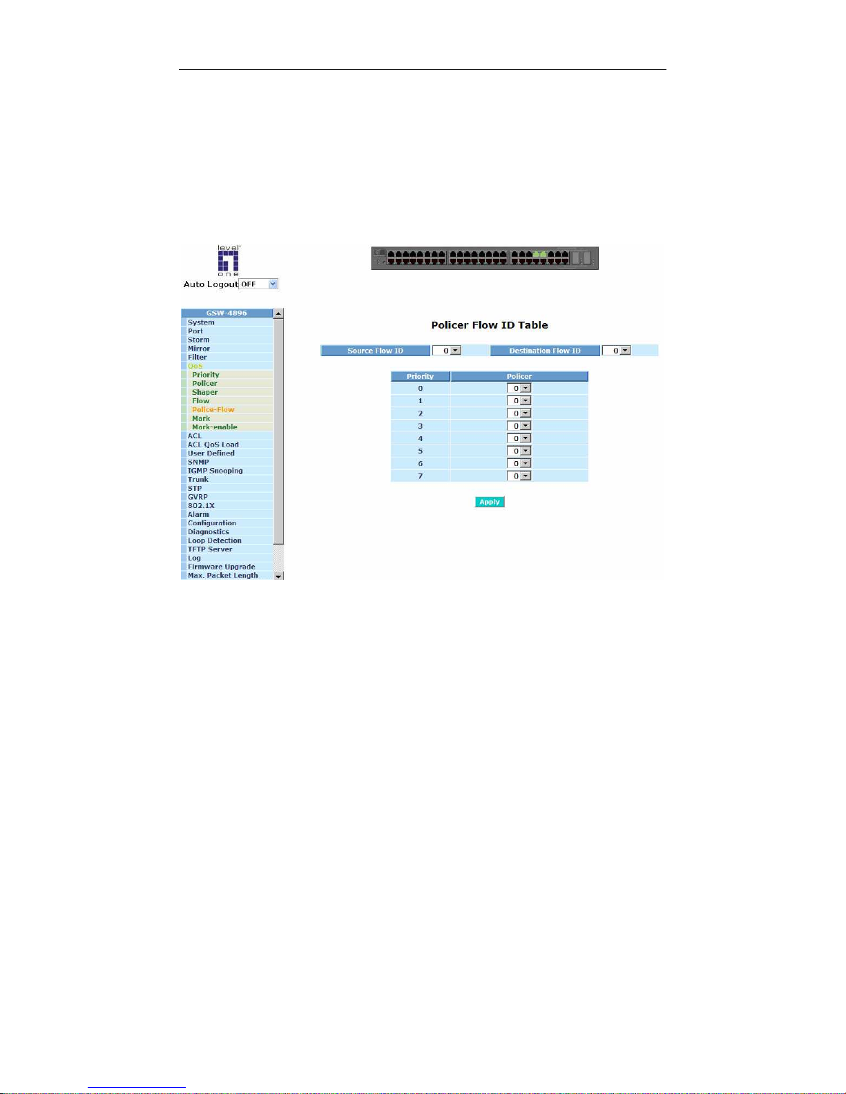
User Manual
85
3-6-5. Police-Flow
Function name:
Policer Flow ID Table
Function description:
Set Policer for each Priority according to Source Flow ID and Destination
Flow ID.
Fig. 3-34
Page 92
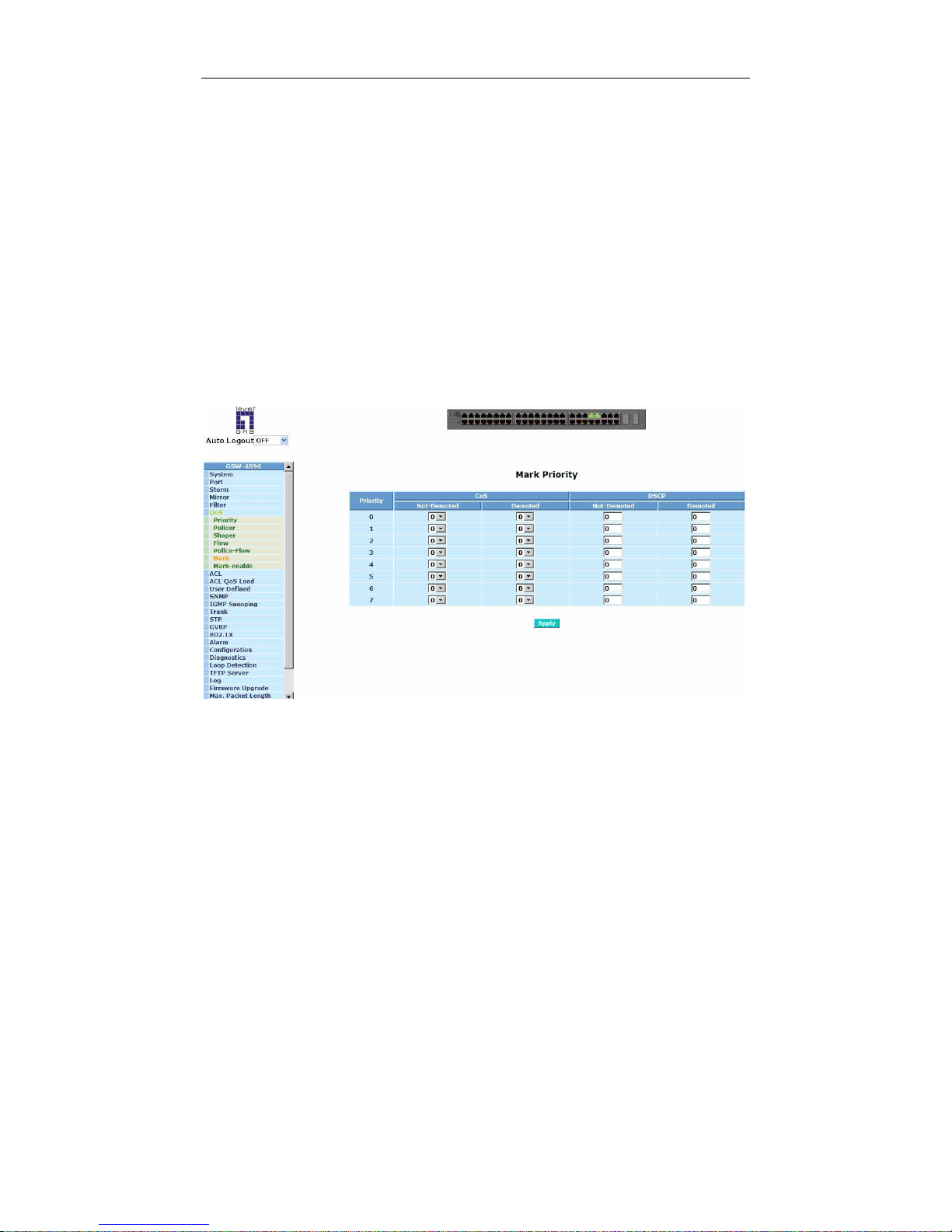
User Manual
86
3-6-6. Mark
Function name:
Mark Priority
Function description:
Mark Priority function allows to mark the priority according to Demoted or NotDemoted tag from CoS and DSCP.
Parameter description:
Not-demoted:
Priority setting according to Not-Demoted for CoS and DSCP.
Demoted:
Priority setting according to Demoted for CoS and DSCP.
Fig. 3-35
Page 93
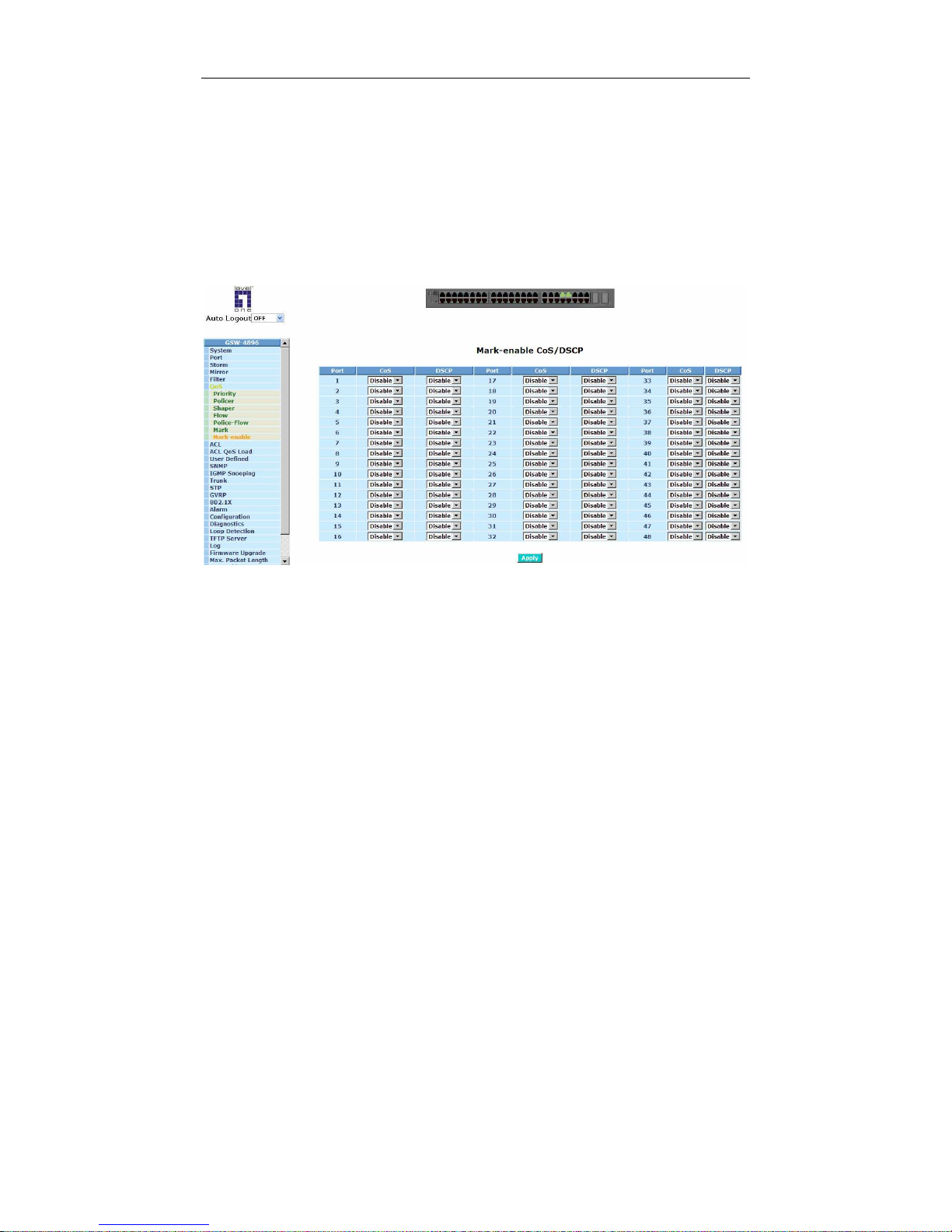
User Manual
87
3-6-7. Mark-enable
Function name:
Mark-enable CoS/DSCP
Function description:
Mark-enable offers the function to mark DSCP and COS for each port on the
switch as desired. Just select the option you want and press <Apply> button
to make the function effect.
Fig. 3-36
Page 94
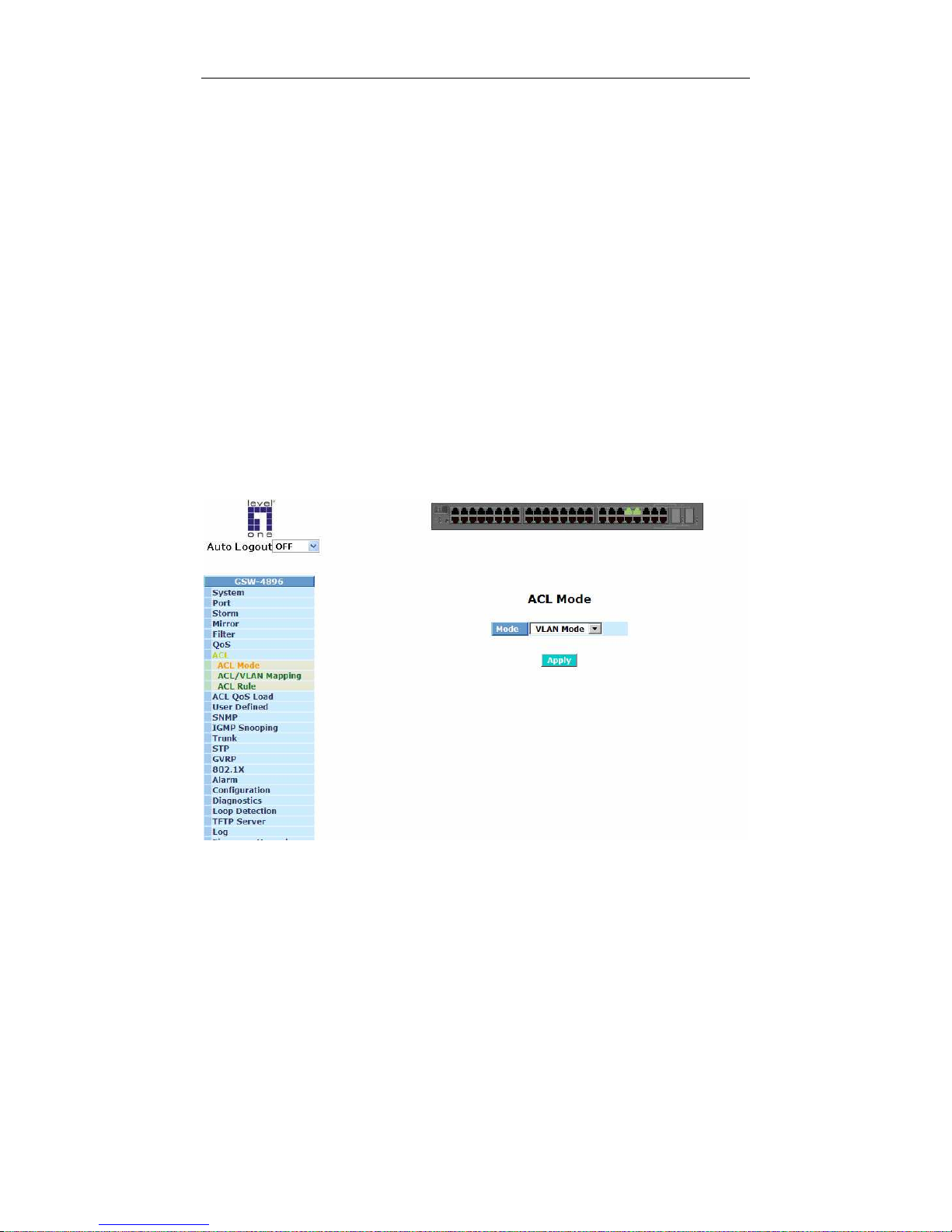
User Manual
88
3-7. ACL
The switch includes 48 ACLs mainly used to filter packets. Each port or VID (256
Active VLAN matched with 48 ACL) maps an ACL, then decides which of the
following actions would take according to the packet’s IP Source/Destination,
EtherType, Protocol, TCP/UDP Source/Destination Port field (5 tuples):
- packet denial or permission
- priority reassignment
3-7-1. ACL Mode
Function name:
ACL Mode
Function description:
This function is used to select ACL mode. Once completing the setting, click
<Apply> button, the setting takes effect.
Parameters description:
Mode: For selecting ACL mode. The default value is “VLAN Mode”.
Fig. 3-37
Page 95
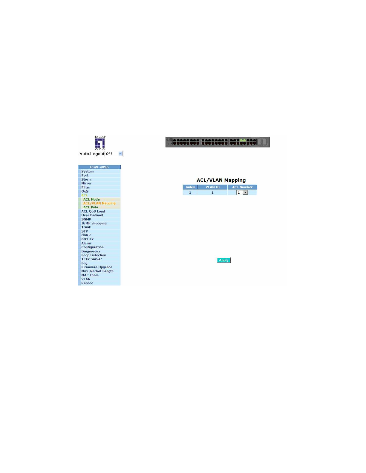
User Manual
89
3-7-2. ACL/VLAN Mapping
Function name:
ACL/VLAN Mapping
Function description:
This function is used to select an ACL to match a VLAN ID. Once completing
the setting, click <Apply> button, the setting takes effect.
Parameters description:
ACL Number:
The number identifier of each ACL for mapping matched VLAN ID.
Fig. 3-38
Page 96
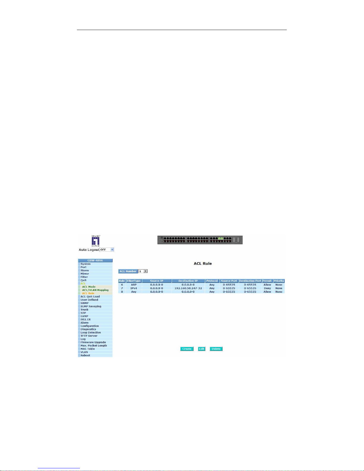
User Manual
90
3-7-3. ACL Rule
Function name:
ACL Rule
Function description:
This function is used to create, edit, or delete ACL rules by clicking <Create>,
<Edit>, or <Delete> button.
Parameters description:
ACL Number:
The number identifier for each ACL.
Rule:
Rule number.
EtherType:
Ethernet type.
Source IP:
The source IP address for this rule.
Destination IP:
The destination IP address for this rule.
Protocol:
The protocol to filter for this rule.
Source Port:
The source port for this rule.
Destination Port:
The destination port for this rule.
Permit:
The permission status for this rule.
Priority:
The ACL rule’s priority.
Fig. 3-39
Page 97
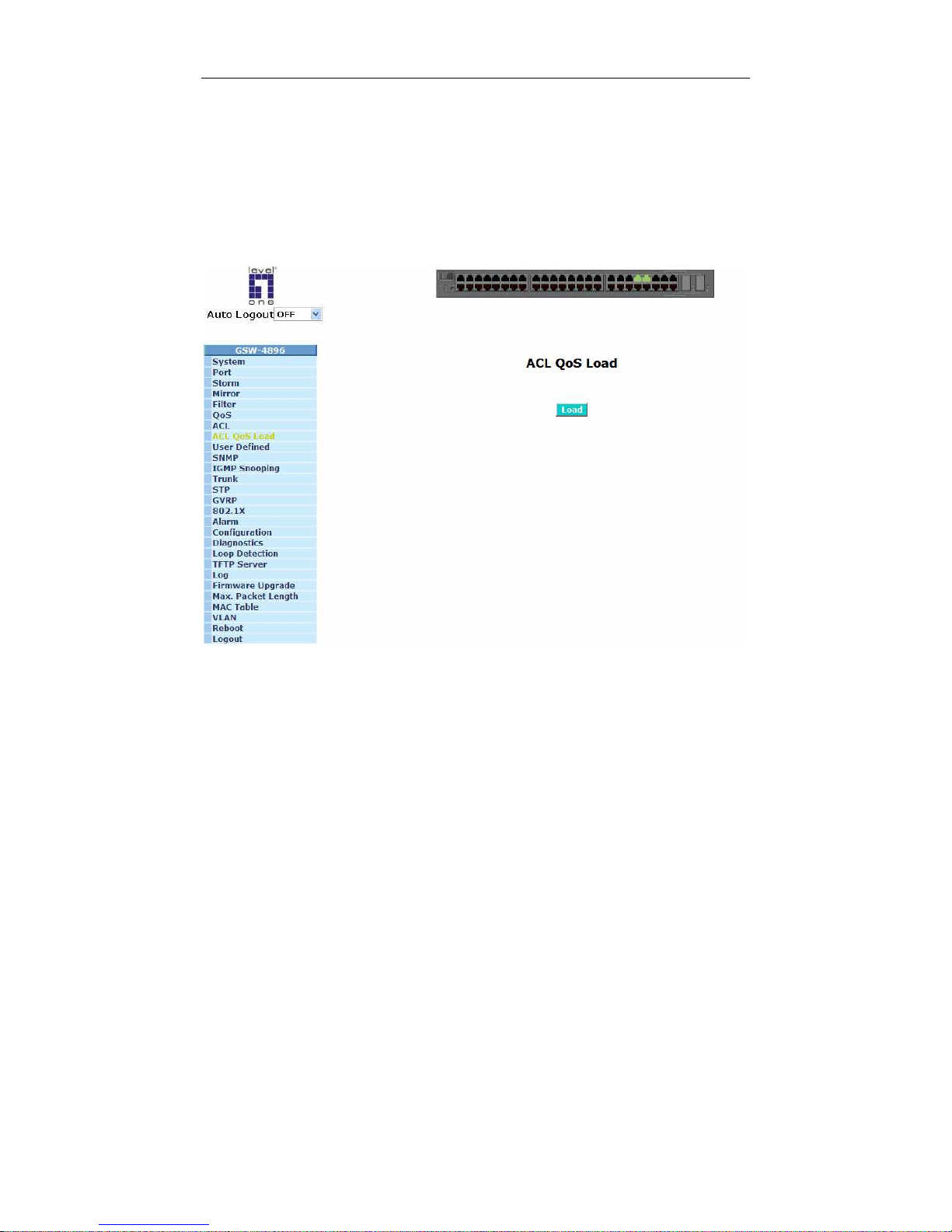
User Manual
91
3-8. ACL QoS Load
Function name:
ACL QoS Load
Function description:
While finishing ACL or QoS settings, please click <Load> button to execute
ACL Qos Load to make the setting takes effect.
Fig. 3-40
Page 98
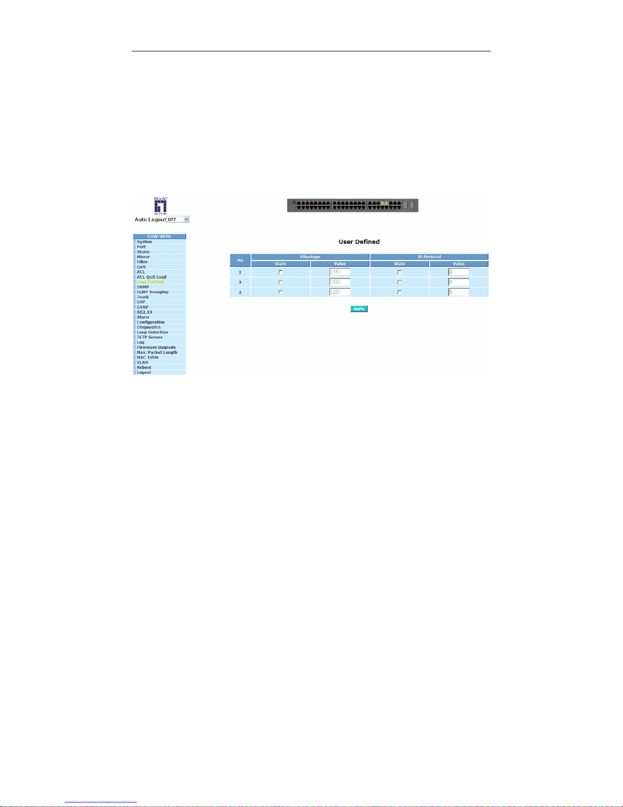
User Manual
92
3-9. User Defined
Function name:
User Defined
Function description:
This function allows users to define three sets of Ether Type and IP Protocol
for the application on ACL or Protocol VLAN settings in the future. Once
completing the setting, click <Apply> button, the setting takes effect.
Fig. 3-41
Page 99
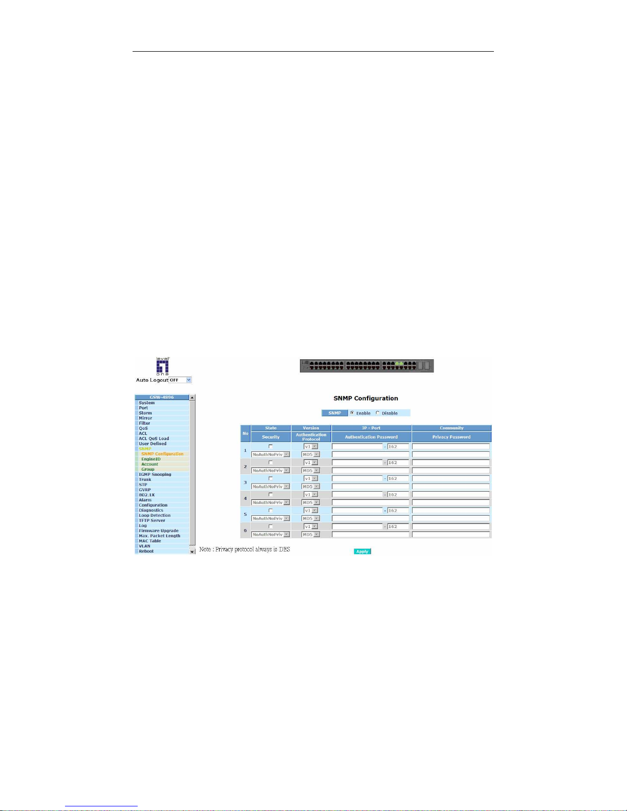
User Manual
93
3-10. SNMP Configuration
Any Network Management System (NMS) running the Simple Network
Management Protocol (SNMP) can manage the Managed devices equipped with
SNMP agent, provided that the Management Information Base (MIB) is installed
correctly on the managed devices. The SNMP is a protocol that is used to govern
the transfer of information between SNMP manager and agent and traverses the
Object Identity (OID) of the management Information Base (MIB), described in the
form of SMI syntax. SNMP agent is running on the switch to response the request
issued by SNMP manager.
Basically, it is passive except issuing the trap information. The switch
supports a switch to turn on or off the SNMP agent. If you set the field SNMP
“Enable”, SNMP agent will be started up. All supported MIB OIDs, including RMON
MIB, can be accessed via SNMP manager. If the field SNMP is set “Disable”, SNMP
agent will be de-activated, the related Community Name, Trap Host IP Address,
Trap and all MIB counters will be ignored.
Function name:
SNMP Configuration
Function description:
This function is used to configure SNMP settings. Once completing the setting,
click <Apply> button, the setting takes effect.
Fig. 3-42 community and trap host setting
Page 100

User Manual
94
Parameters description:
SNMP:
The term SNMP here is used for the activation or de-activation of SNMP.
Default is Enable.
State:
You may enable SNMP State by checking the box.
Security:
Select encryption or non-encryption.
Version:
You may choose V1, V2, or V3 Trap.
Authentication Protocol:
Select MD5 or SHA authentication.
IP-Port:
IP address and Port number. Default port number :162
Authentication Password:
A password is required and is used to authenticate the user credentials.
Community:
You can enter an SNMP community if you have it; otherwise the default is
"Public."
Privacy Password:
A second password is used to encrypt the details of the SNMP request
using DES encryption.
Note 1: To encrypt Authentication would encrypt whole SNMP V3 Trap packet.
Note 2: Only DES encryption is supported for Community.
Note 3: When V1/V2 selected, it is not allowed to set encryption and password.
 Loading...