

Page 1

LevelOne
User Manual
PPM-1000
PoE Power Measurement
Page 2
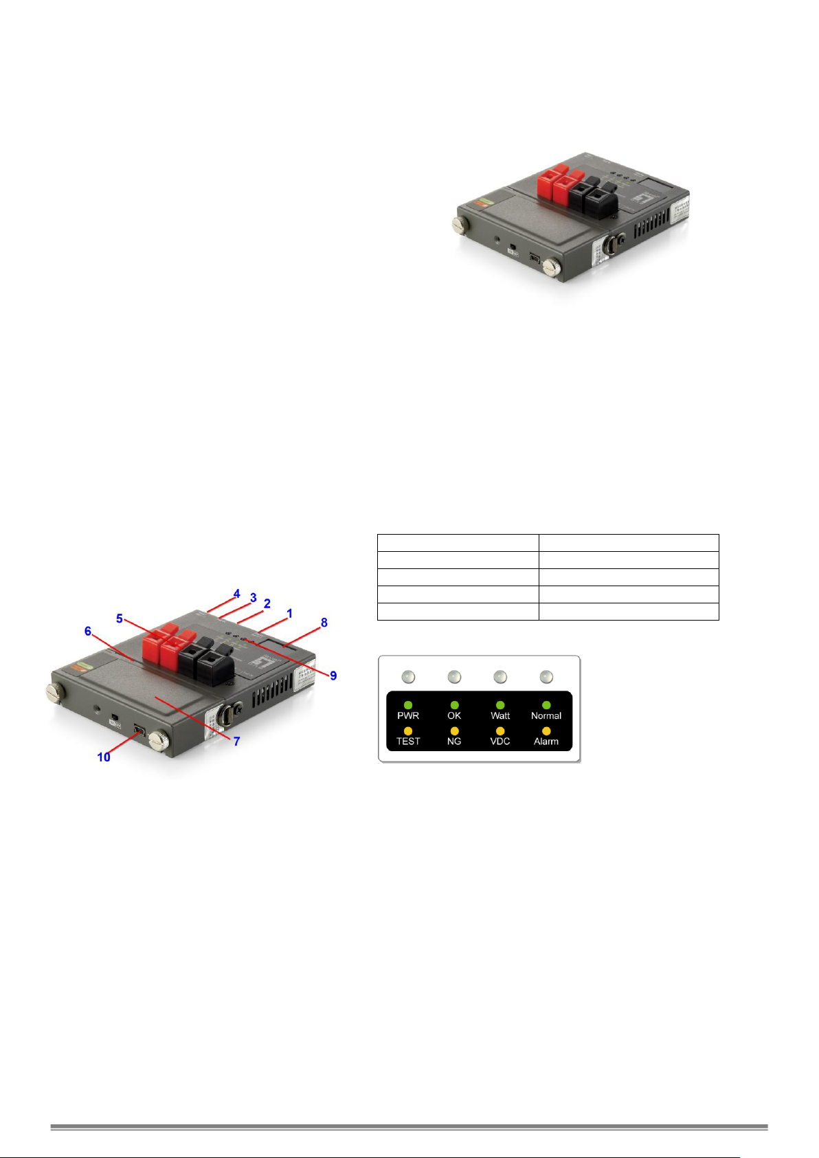
Display/Set(+) Button
Console Port (for upgrade)
Network RJ45 UTP Port
Start/Set(-) Button
Power Probing Terminal
USB Power Port
External Battery Pack
3-Digit Display
LED Indicators
USB Port (charge battery)
Console Port
Connect PPM-1000 to PC by console cable. Run HyperTerminal in
Windows at 38400 bps (Baud Rate) to connect and open the default
settings. Press Ctrl+C to enter main menu. Select A to check
firmware version or B to update firmware with using X modem
protocol.
On-site PoE Power Measurement
PPM-1000 OVERVIEW
PPM-1000 is a handheld tester for the applications of
Power over Ethernet (PoE). It performs on-site
measurement of the running voltage and supplying power
at the end of Ethernet cable terminal in any length for PoE
PSE/PD devices which complies with IEEE802.3af.
PPM-1000 provides for field engineer a convenient on-site
tester with compact size to verify PoE, measure the voltage,
and examine the maximum power from PSE to PD at the
end point of the Ethernet cable.
Powered by replaceable and rechargeable battery, the
portable PPM-1000 allows the technical personnel to test
terminal for PD in the fields.
With 3-digit LED display, it shows the PoE status and the
maximum power available from PSE. Pass/Fail LED
indicators may inform technician the results instantly.
With built-in Terminal Block connectors, PPM-1000 is able
to clamp and hold the bare wires of network cable for test
before clamping into the RJ-45 connector. PPM-1000 is
truly the best handy tool for the installation of PoE PD
devices. With the tester, it shall successfully guarantee
the PoE power provision to PD devices.
Mechanical Description
LED Indicators
Buttons and LED Indicators
Start/Set(-) Button:
Set the desire maximum power (Watt) for test:
Push and hold Start/Set(-) button for 3 seconds to enter for
configuration of maximum power limit. It confirms with a
beep sound and the 3-digit LED display start blinking.
Press the Start/Set(-) or Start/Set(-) buttons to set the
desired power limit Then, push and hold Start/Set(-) button
for 3 seconds to exit the configuration stage.
Press once to start measurement and press again to finish
the test procedure.
Display/Set(+) Button
Select options for displaying the Voltage, Power
Consumption Limit and Temperature.
While LED PWR/TEST is in orange during testing, the
3-digit Display shows the instantaneous power values.
While LED PWR/TEST is in green, the 3-digit display will
show the final result of power measurement.
Note that if the LED OK/NG is in green OK, it indicates the
power from PSE is able to provide the desired power
consumption limit; else LED OK/NG will be in orange NG,
indicating the power is not enough for the PD requirement.
Page 3

Detection Range:
Watt: 0~96W
Voltage: 24~60V (Over 40V is
required initially.)
Current: 0~2A
Power:
External Battery Pack
Provide 7 hours of standby time, shorter if
operations keep going.
Overload Protection:
Operation Temp:
Humility:
Polyswitch over current protection
-20°C ~ 50°C
0% ~ 85% RH
Battery
Pack:
Li-Ion, 2,400 mAh, 3.7 V,
Charged by USB cable
Charge Time: 3~4 hours
PWR/TEST LED
When test is started, PWR/TEST LED is blinking orange
When test is finished, PWR/TEST LED keeps orange
When test is finished ready for next test, PWR/TEST LED
keeps green
WATT/VDC LED
When LED is in green, the 3-digit LED display shows the
PoE power in unit of Watt.
When LED is in orange, the 3-digit LED display shows the
PoE DC voltage.
When LED is off and Normal/Alarm LED is green, the
3-digit LED display shows the value of temperature.
OK/NG LED
When LED is in green, it indicates the power from PSE is
able to provide the desire maximum power to PD.
When LED is in orange, it indicates the power is not
enough to support the desire maximum power to PD.
When LED is in blinking orange, the measurement is
failed and the Current is too high (over 2A).
When LED is off and Normal/Alarm LED is in orange, the
measurement is failed and the device is over-temperature
(over 100℃).
Normal/Alarm LED
When LED is in green, the LED digits display shows the
value of temperature
When LED is in orange, the device is over-temperature
(over 100℃).
Measurement Procedures
Hardware connection
Screw tightly the battery pack and connect the cable
as the illustration. Switch power on at the bottom.
For cable bare wires, these can be clamped into
Power Probing Terminal directly for Mode A (Power via
Pin 1, 2, 3, 6) or Mode B (Power via Pin 4, 5, 7, 8) of
IEEE802.3af standard.
Note: Network cable can not be connected to UTP port
and Power Probing Terminal simultaneously.
Operation Procedure
1. To set desire maximum power from PSE to PD for test.
Push and hold Start/Set(-) Button for 3 seconds to enter for configuration of maximum power limit. It confirms with a beep
sound and the 3-digit LED display start blinking. Press the Start/Set(-) or Start/Set(-) buttons to set the desired power limit
Then, push and hold Start/Set(-) button for 3 seconds to exit the configuration stage.
2. Press Start/Set(-) Button to start power measurement test.
The PWR/TEST LED will start orange blinking, and the 3-digit LED display will show the changing power measurement. After
the test is done, if the OK/NG LED is green ON, it indicates that the power from PSE could support the desire maximum power.
If the OK/NG LED is orange ON, it indicates that the power from PSE could NOT support the desire maximum power.
Note that if PPM-1000 is over 50°C, the test will be prohibited. Wait till it cools down for normal start. Once it starts testing, the
tolerated temperature will be up to 100°C.
3. Press Display/Set(+) Button to show the real-time value or measurement results.
Show value of measurement results while the PWR/TEST LED is orange after test.
Press once Display/Set(+) Button to show the value of power measurement when the WATT/VDC LED is green.
Press again Display/Set(+) Button to show the value of DC voltage when the WATT/VDC LED is orange.
Press again Display/Set(+) Button to show the device temperature when the Normal/Alarm LED is green.
Show real-time value (by pressing Start/Set(-) Button) while the PWR/TEST LED is green.
Press once Display/Set(+) Button to show the value of power measurement when the WATT/VDC LED is green.
Press again Display/Set(+) Button to show the value of DC voltage when the WATT/VDC LED is orange.
Press again Display/Set(+) Button to show the device temperature when the Normal/Alarm LED is green.
4. Alarm notification
When Normal/Alarm LED is orange ON, it indicates that PPM-1000 is over-temperature (over 100℃). Please stop the
measurement until the device is cool down below 50°C.
Specifications
 Loading...