

Page 1

LevelOne
KVM-0830/KVM-1630
8/16-Port Combo KVM Switch
w/ Remote Console Port
User Manual
Ver. 1.00-0701
Page 2

2
Table of Contents
1. INTRODUCTION .............................................................................................................3
2. KEY FEATURES .............................................................................................................4
3. PACKAGE CONTENT.....................................................................................................4
4. TECHNICAL SPECIFICATION........................................................................................5
5. SYSTEM REQUIREMENT...............................................................................................5
6. CABLE DIAGRAM ..........................................................................................................6
7. FRONT PANEL................................................................................................................7
8. REAR PANEL..................................................................................................................8
9. HARDWARE INSTALLATION.........................................................................................8
10. OPERATION................................................................................................................11
11. DAISY CHAIN CONNECTION.....................................................................................14
12. ON SCREEN DISPLAY ...............................................................................................16
13. TROUBLESHOOTING ................................................................................................33
14. CERTIFICATION .........................................................................................................34
Page 3
3
1. Introduction
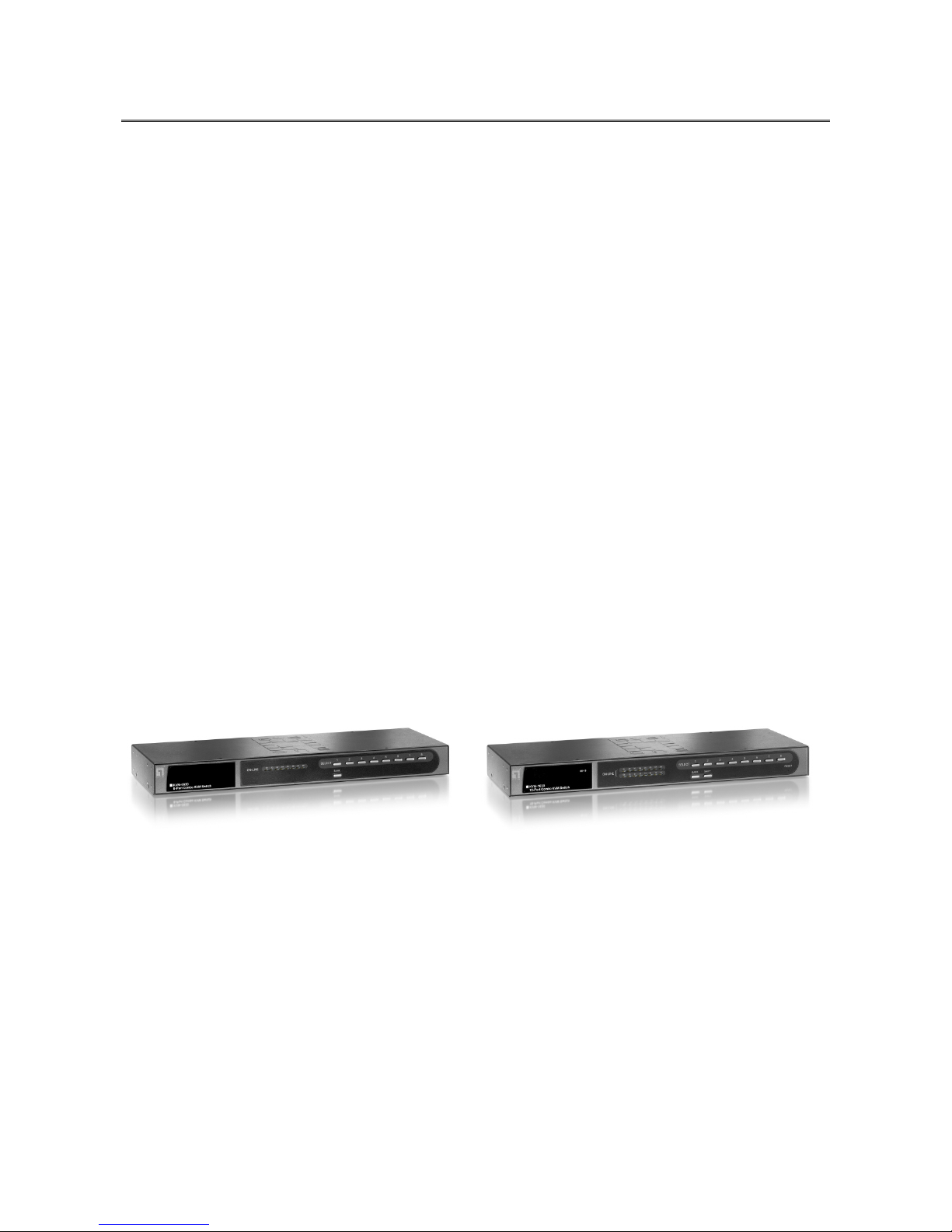
Thank you for purchasing LevelOne KVM-0830/1630 Combo KVM Switch. The KVM
Switches offer the most reliable and efficient way of managing multiple computers in server
rooms where space is at a premium. On Screen Display (OSD) features computer naming,
computer selection, status indication, auto scan and much more. Up to 128 servers can be
easily managed by cascading multiple KVM switches to expand the capacity.
Revolutionized video enhancement technology ensures superb quality up to 1920 x 1440.
KVM-0830/1630 supports host PC with PS/2 and USB interface. The convenient HDDB-15
to VGA+PS/2+USB cable allows user to connect to different kinds of PC interfaces by the
same cable. Users no longer need to prepare two kinds of cables for their PCs or servers
with different kinds of interfaces. Users can save their time and cost when building their
system.
Besides the USB console port, KVM-0830/1630 provide an Cat.5 remote console port for
users to access KVM switch remotely with the KVM-9007 Cat.5 Receiver. After making
connection between KVM switch and Cat.5 receiver by Cat.5/5e/6 cable, users can control
their system remotely and the distance can be up to 300 meters. Users can use their
existing LAN cables to do the remote control, this also saves their cost and reduce the
complexity. Some server room environments are too noisy for people or unsuitable to work
there for a long time, this remote control feature is an ideal solution for these situations.
KVM-0830 KVM-1630
Page 4
4
2. Key Features
8/16 ports Combo KVM switch with 19” rack-mounted design
Combo interface with PS/2 and USB PC supports
Supports one Cat.5 remote console up to 300 meters away from KVM switch*
Supports DOS, Win98SE/2000/XP, WinNT, Netware, Unix, Linux
Supports iMAC, Power MAC and Sun Microsystems with USB port
Hot Plug - add PCs or remove connected PCs for maintenance without powering down
the KVM switch or PCs
High VGA resolution - up to 1920X1440, bandwidth: 200MHz
Easy PC selection via On Screen Display Menu, Push buttons, Hot keys
Support eight characters password protection and search PC server name
Auto scan mode for monitoring PCs and flexible scan time from 5~99 seconds
Keyboard status restored when switching PCs
LED display for easy status monitoring
Buzzer sound for switching port confirmation
Built-in one daisy chain port for cascading up to 8 KVM-0830/KVM-1360
* The KVM-9007 Cat.5 Receiver is required for the Cat.5 remote control, it is highly
recommended to use Cat.5e cable when the connection is shorter than 150 meters, and to
use Cat.6 cable when the connection is between 150 and 300 meters.
3. Package Content
KVM-0830 / KVM-1630 1 PCS
Power Adapter DC12V, 1.0A 1 PCS
Rack Mount Kit 1 SET
User Manual 1 PCS
Note:
All cables are optional, please contact your local distributor for more information
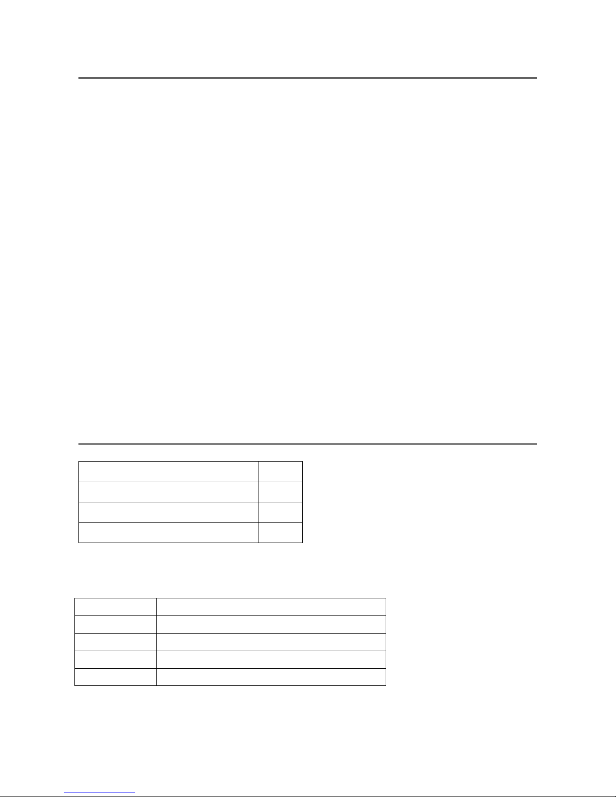
Model No Description
ACC-2101 1-to-3 1.8m cable for PS/2 and USB port
ACC-2102 1-to-3 3.0m cable for PS/2 and USB port
ACC-2103 1-to-3 5.0m cable for PS/2 and USB port
ACC-2109 90cm Daisy Chain cable
Page 5
5
4. Technical Specification
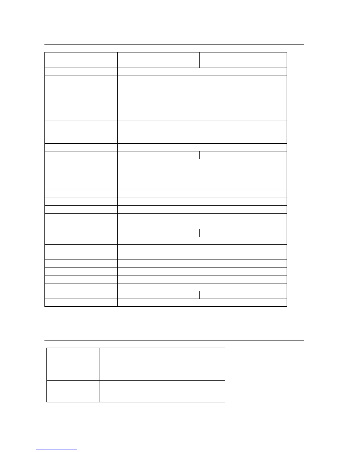
Model No. KVM-0830 KVM-1630
PC Port 8 16
Console Port One USB and one Cat.5
PC Port Connector
(All Female Types)
VGA HDDB 15pin
Console Port Connector
(All Female Types)
Local Console: USB Keyboard (USB Type A)
USB Mouse (USB Type A)
VGA HDDB 15pin
Remote Console: RJ-45 8P8C
Daisy Chain Port
Connector
(All Female Type)
VGA HDDB 15pin
PC selection On Screen Display Menu, Hot Key, Push Button
PC Port LED 8 16
Bank 7 segment LED 3
On Screen Display
Control
Yes
Scan Intervals 5~99 Sec.
Keyboard Emulation PS2 or USB
Mouse Emulation PS2 or USB
VGA Resolution 1920X1440
Bandwidth 200MHz
Daisy Chain MAX Level 8 levels
MAX PC Connection 120* 128
Housing Metal
KVM Switch Power
Adapter
DC 12V, 1A
Operation Temperature 0~50℃
Storage Temperature -20 ~ 60℃
Humidity 0~95%, Non-Condensing
Size 19” Rack Mount / 1RU
Weight (g) 2090g 2300g
Dimension (mm) 445(L) X 160(W) X45 (H)
* Cascading 1 KVM-0830 + 7 KVM-1630 together
5. System Requirement
Model No. KVM-0830 / KVM-1630
Local Console
side
One VGA Monitor
One USB Keyboard
One USB Mouse
Computer side
HDDB 15 pin male to HDDB 15 pin + Mini
Din 6 pin + USB special cables
Page 6
6
6. Cable Diagram
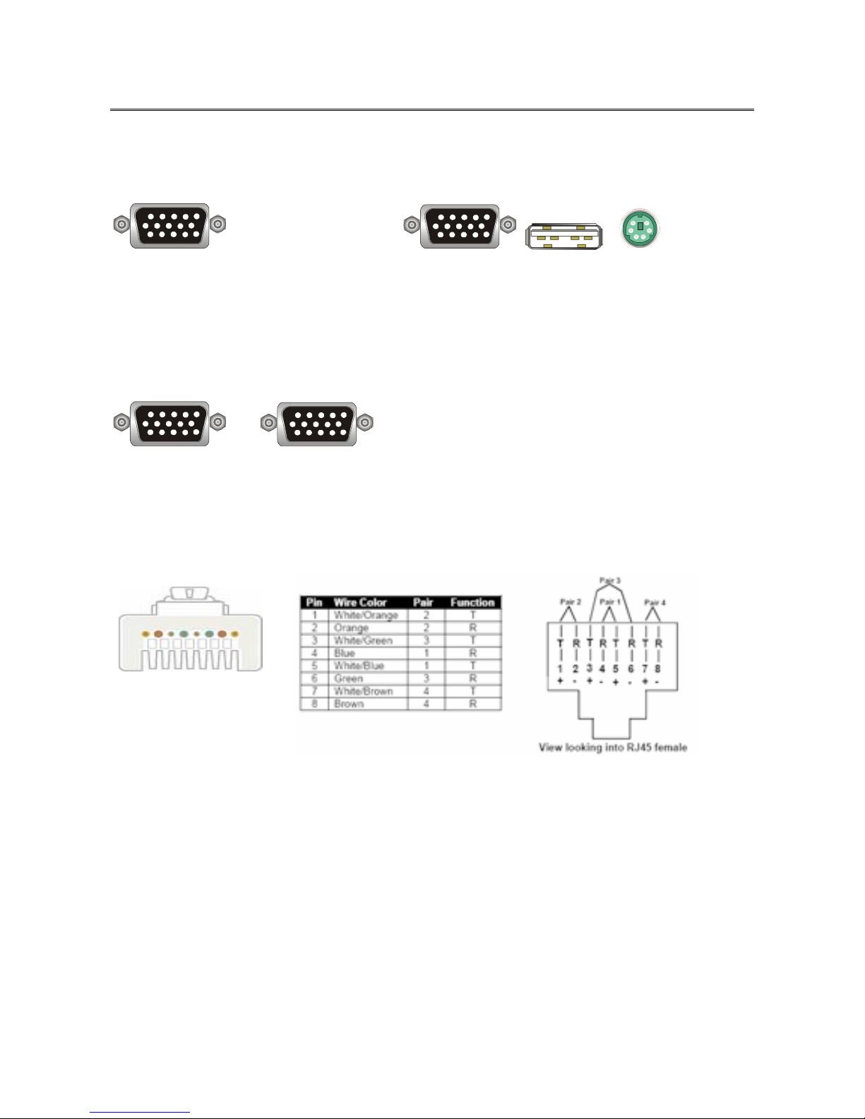
PC Port Special Cable: (ACC-2101, ACC-2102, ACC-2103)
HDDB15 pin male to one HDDB 15 pin male, one Mini Din 6 pin and one USB special
cables
------------Æ
Daisy Chain Cable: (ACC-2109)
VGA Cable:
HDDB15 pin Male to Male
Cat.5/5E/6 Straight Through UTP/STP Cable:
8P8C
Page 7
7
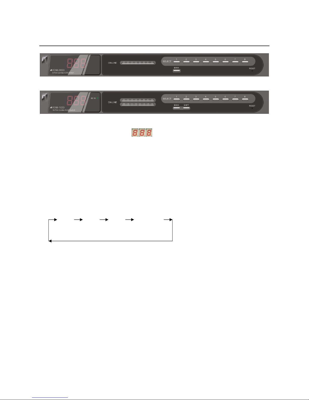
7. Front Panel
KVM-0830:
KVM-1630:
7-Segment BANK LED indication :
This KVM switch has three 7-segment LEDs to indicate which bank and port is selected.
The first digit of 7-segment LED indicate the bank you selected and the last two digits
indicate which port you select on this bank.
ON-LINE LED indication:
When the host PC is powered on, the ON-LINE LED (Blue color) of corresponding port will
be lit in solid blue. If the PC is powered off or PC port is empty, the power LED won’t be lit.
The BANK button:
If you want to view the KVM switch on next bank, please press “BANK“ button. The bank
LED will be changed from bank 1 to the maximum daisy chain level and then to press
“BANK“ push button once back to the bank 1.
Bank 1 Bank 2 Bank 3 MAX. BANK
Push Buttons (1~8):
To switch from one to another port, please press the push button for the destination port on
the front panel.
SHIFT Button:
For 16 ports KVM switch, please press “SHIFT” button (9-16 LED on) and individual button
1~8 simultaneously in order to select the port 9 to port 16.
For example: Pressing “SHIFT” button and button 5 simultaneously, the thirteen PC port
select LED is selected.
Note:
ON LINE status may still lit on after PC/Server shut down when USB KB/Mouse connected
to PC ports. It’s because the USB port is powered continuously by PC/Server
motherboards, even it shut down already.
Page 8
8
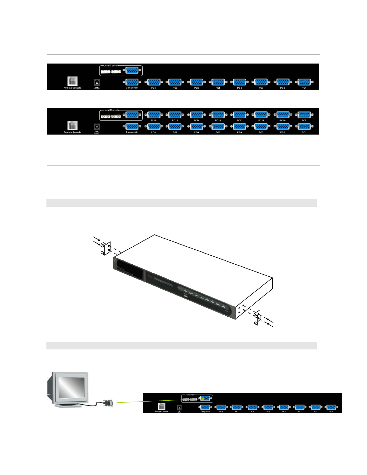
8. Rear Panel
KVM-0830:
KVM-1630:
9. Hardware Installation
Before installation, please make sure all of peripherals and computers have been turned off.
This example of installation is based on KVM-0830 and the procedure of KVM-1630 is the
same.
Step 1
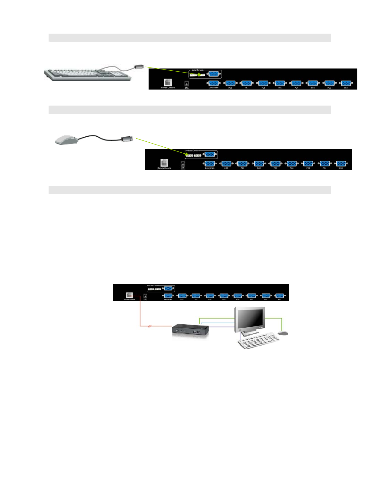
KVM-0830 / KVM-1630 can be mounted in a standard 19-inch equipment rack or on a
desktop. To mount to a rack, attach the brackets to the device using the screws provided in
the rack-mount Kit.
Step 2 (Local Console)
Connect the monitor to the HDDB-15 female port of the local console ports on the back of
the KVM.
Page 9
9
Step 3
Connect an USB keyboard to the KVM Switch.
Step 4
Connect an USB mouse to the KVM Switch.
Step 4-1 (Remote Console)
Extending your PC console up to 1000 feet away:
(1) Make sure that the Cat.5 cable is straight through type.
(2) Plug one end of Cat.5 cable into the remote console port of KVM switch and the other
end of Cat.5 cable into the RJ-45 port of KVM-9007 Cat.5 receiver.
(3) Connect keyboard, mouse and monitor to the Keyboard/Mouse port and Monitor port
of KVM-9007.
(4) Connect Local PC to KVM-9007 by using the HDDB-15 to the VGA+PS/2+USB cable
(ACC-2101/ACC-2102/ACC-2103).
KVM-9007
Cat.5 Receiver
300 Meters
NOTE:
1. Local console and Remote console of the KVM switch have the same
priority to control computers connected to the KVM switch. The display
output is the same at the local and remote console monitors. The priority
mechanism is: the first move port has the priority and will release the
priority if it did not keep input for 2 seconds.
2. If the video signal is foggy or un-cleared on the screen, please check if the
VGA connector of monitor is well connected to KVM-9007 Cat.5 receiver.
3. For the best display result, it is highly recommended to use Cat.6 cable
when the connection distance is longer than 150 meters.
Page 10
10
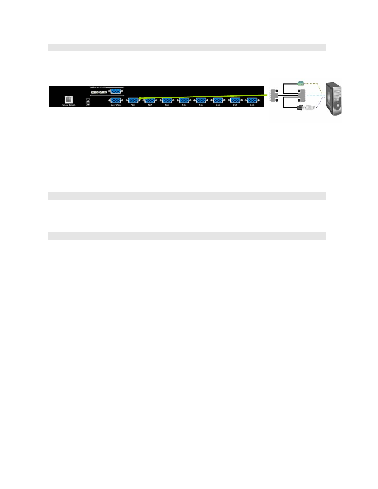
Step 5
The PC port connector is HDDB-15 pin type. Plug the HDDB-15 end of the KVM cable
(HDDB-15 to VGA+PS/2+USB type) into PC port on the rear of KVM switch unit.
The Rear Side of PC
(a) For PS/2 computers - Plug the PS/2 connector into the PS/2 mouse port of PC. And to
use the USB to PS2 adaptor to convert the USB connector into PS/2 interface, then
connect it to the keyboard port of PC.
(b) For USB computers - Plug the USB connector into the USB port of PC and no need to
connect the PS/2 connector to the PC.
Step 6
Double-check all of the connections. You can check the color of keyboard and mouse
connector to make sure the keyboard and mouse connectors are plugged to the correct
ports.
Step 7
Attach the power supply to the KVM unit and plug the other end into a receptacle. The Port
1 LED will be lit up, and you will hear a beep. Please switch on your monitor.
Note:
Please remember to plug the power adapter. Although the PCs connected to KVM Switch
are able to support enough power to the stand alone switch, KVM switch still needs a
power adapter for daisy chain more banks. Unexpected status may occur If you try to
daisy chain more KVM switches without plugging the power adapter.
Page 11
11
10. Operation
The power on state of KVM-0830/1630:
When you power on the KVM switch, it will prompt a login window for key-in USER NAME
and PASSWORD. For more details, please refer to OSD menu operation.
The push buttons 1~8:
To switch from one to another port, please press the push button for the destination port on
the front panel. For 16 ports KVM switch, please press “shift” button (9-16 LED on) and
individual button 1~8 simultaneously in order to select the port 9 to port 16.
For example: Pressing “shift” button and button 5 simultaneously, the thirteen PC port
select LED is selected.
ON-LINE LED indication:
When the host PC is powered on, the ON-LINE LED of corresponding port will be lit in solid
blue. If the PC is powered off or PC port is empty, the power LED won’t be lit.
The BANK button:
If you want to view the KVM switch on next bank, please press “BANK“ button. The bank
LED will be changed from bank 1 to the maximum daisy chain level and then to press
“BANK“ push button once back to the bank 1.
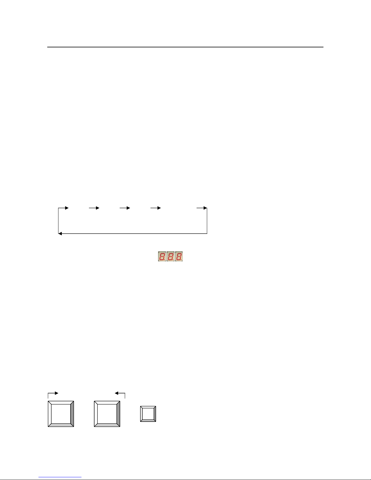
Bank 1 Bank 2 Bank 3 MAX. BANK
7-Segment BANK LED indication :
This KVM switch has three 7-segment LEDs to indicate which bank and port is selected.
The first digit of 7-segment LED indicate the bank you selected and the last two digits
indicate which port you select on this bank.
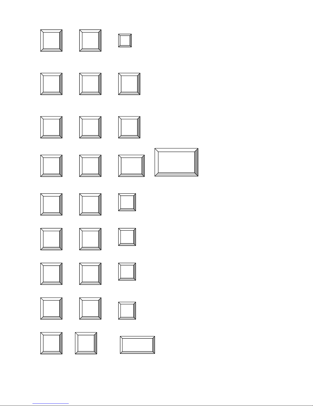
Keyboard Hot Key Commands:
You can switch between the banks or ports through simple hot key. The default hot key is
“CAPS LOCK“ and the user could change hot key as your convenient application. If you
prefer to use a different hot key, you change the default hot key in the OSD menu.
To send commands to KVM switch, please press the “CAPS LOCK” key twice within 2
seconds. You will hear a beep for confirmation and the keyboard is in hot key mode. If you
don’t press any key during hot key mode over 2 seconds, the hot key mode is void and the
keyboard will back to under operation system control state.
Below are the different hot key commands:
within 2 seconds
+ + =
Previous Channel
Caps
Lock
Caps
Lock
↑
Page 12
12
+ + =
Next Channel
(Note: You can press “up arrow key” or
“down arrow key” for longer time to
speed up the selecting)
+ + = Previous Bank
+ + =
Next Bank
+ + =
Select PC port
+ + =
Beeper (Note: The default Beeper function is
ON and beeper control is only for
available for Scan Mode )
+ + = Auto Scan (To leave Auto Scan mode, press
any key or SPACE bar)
+ + =
Logout (To set up Console Security “ON“ to
“OFF“)
+ + =
OSD setting back to factory default value
(Note: Not including password)
+ + =
On Screen Display Menu
Caps
Lock
Caps
Lock
Caps
Lock
Caps
Lock
Caps
Lock
Caps
Lock
B
S
Bank
No 1~8
Port No.
Caps
Lock
Caps
Lock
↓
Caps
Lock
Caps
Lock
Caps
Lock
Caps
Lock
Page
Up
Page
Down
Caps
Lock
Caps
P
Caps
Lock
Caps
Lock
Lock
Caps
Lock
Caps
Lock
R
Space Bar
1~08 (8 ports)
1~16 (16 ports)
Page 13

13
Example:
A. To access a computer at port 4 of the 3rd bank, you can press through hot key as below:
Caps lock + Caps lock + 3 + 04
B. To access a computer from Bank 3 to Bank 4, you can press through hot key as below:
Caps lock + Caps lock + Page Down
Note:
Bank no. and port no. selection must be made using the numeric keys on the keyboard.
Numeric keys on the keypad are not available as a hot key command.
Page 14
14
11. Daisy Chain Connection
Note:
Make sure that power to all the devices you will be connecting up have been turn off. You
must unplug the power cords of any computers.
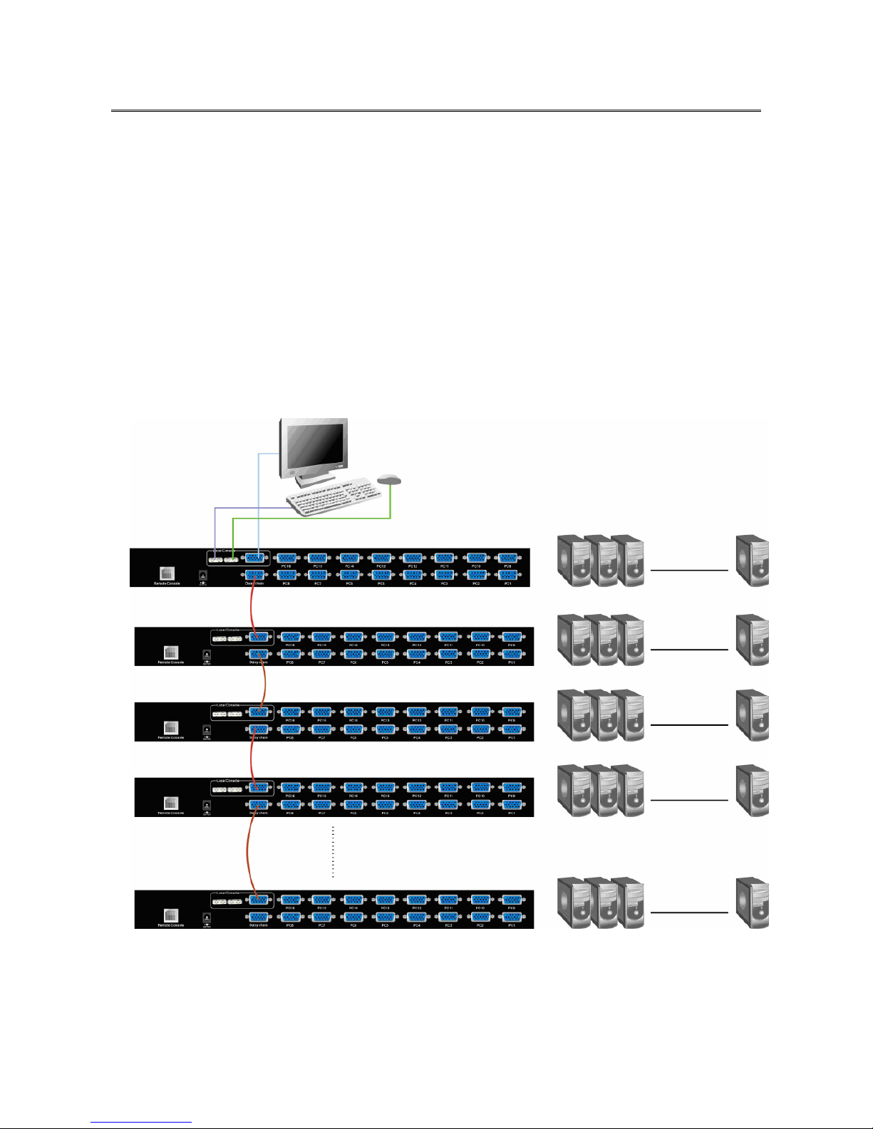
A. Turn on the KVM switches first then connect the daisy chain cable (ACC-2109). Use one
end of daisy chain cable to connect the chain in of daisy chain ports of bank 1 KVM
switch and the other end of daisy chain cable for chain out of daisy chain ports of bank 2
KVM switch.
B. Please repeat step A to daisy chain more bank as you want. Add the KVM switch one at
a time The maximum daisy chain bank is eight levels. The bank 1 OSD menu and front
panel button will be used to do while KVM system after daisy chain, other KVM switch
OSD will be disabled. If you daisy chain KVM-830 and KVM 1630 please use the 16 port
at the bank 1.
Page 15
15
Daisy Chain Operate and Display
The BANK button:
If you want to view the KVM switch on next bank, please press “BANK“ button. The bank
LED will be changed from bank 1 to the maximum daisy chain level and then to press
“BANK“ push button once back to the bank 1.
Bank 1 Bank 2 Bank 3 MAX. BANK
Display Example:
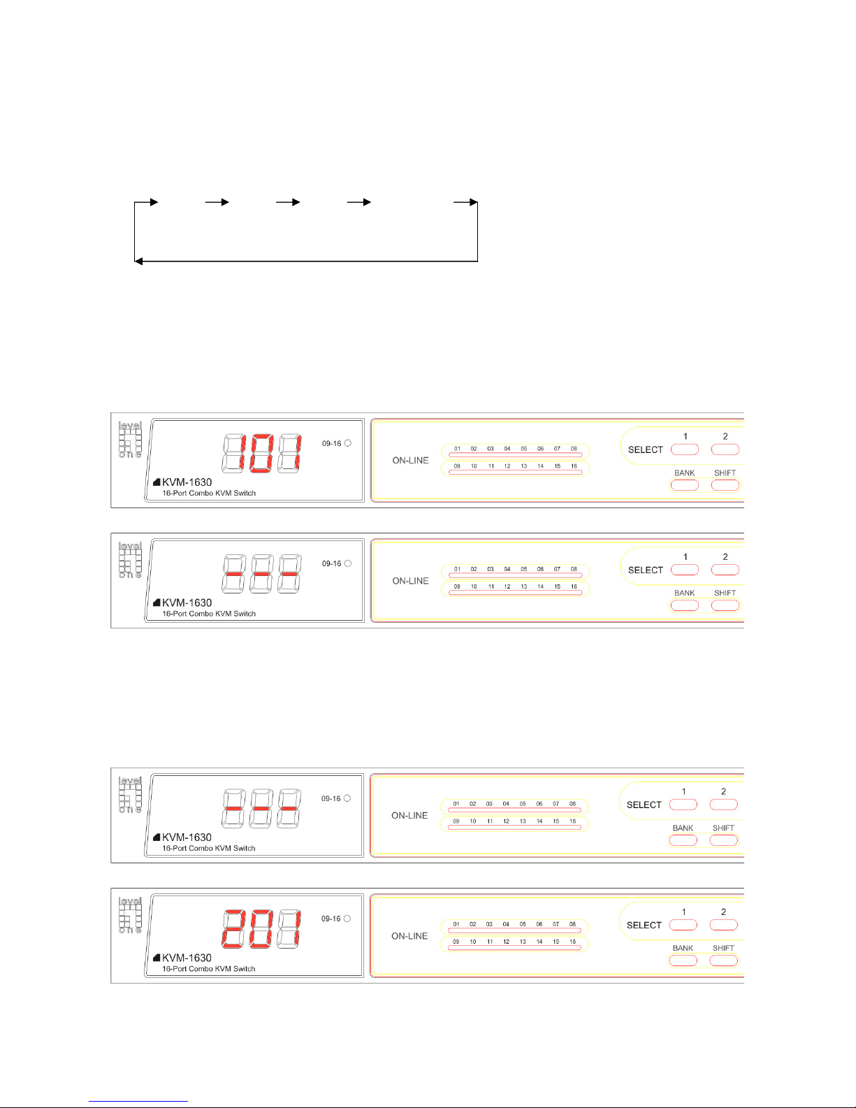
When multiple KVM switches are cascading, user can control all the devices through
BANK1 (Master) only. The following diagram shows the BANK1, Port1 is in control right
now, and SELECT button is switching between PCs/Servers within BANK1.
After press BANK button to switch to BANK2, the following diagram shows the BANK2,
Port1 is in control right now, and SELECT button is switching between PCs/Servers within
BANK2.
Bank1 (Master)
Bank2 (Slave)
Bank1 (Master)
Bank2 (Slave)
Page 16

16
12. On Screen Display
On Screen Display Menu provides a menu driven interface to handle a multi-language
menu, access security, computers switching process, to name a PC name or server name,
to set up the password/window display time and to search PC port name if you don’t
remember it.
This KVM switch allows both local and remote consoles to access the PC simultaneously.
There is only one user has the access right to control the PC and the other users could view
the same PC screen. Once one user gets the access right and stop input anything or move
the mouse for 2 seconds, the access right will be released, both two users have the same
priority to compete the access control right again.
Note:
OSD accepts capital letters only. (Uppercase)
This On Screen Display (OSD) Menu has 3 tiers dialog window:
1. Login In Window
After powering on this KVM, user will be asked for user name and password in the login
window. There are two kinds of user authority --- SUPERVISOR and ADMINISTATOR.
The factory default login user is SUPERVISOR. Before creating any administrator user’s
name and password, none of administrator users could access OSD menu.
When you login as Supervisor, please create one new supervisor and eight
administrator names at USER SECURITY menu.
2. Main Menu --- 9 menus for KVM switch settings.
3. Sub-Menu --- Select from options.
Press “Scroll + Scroll + Space Bar” to enter On Screen Display (OSD) Menu, the Login-in
window as below will appear:
PASSWORD
_ _ _ _ _ _ _ _
USER NAME
_ _ _ _ _ _ _ _
The USER NAME and PASSWORD should be filled with eight digits and the default user
name and password value is eight zero “ 00000000 “. After login in MAIN MENU, you
need go to USER SECURITY and could set up the administrator user name and his
password.
Page 17

17
To type default user name is eight zero “00000000” and press “Enter”.
To type default password is eight zero “00000000” and it will prompt eight star symbol
“********” and then press “Enter“.
If the password you entered is wrong, it will back to the login window as power on state of
KVM switch.
USER NAME
00000000
PASSWORD
_ _ _ _ _ _ _ _
USER NAME
00000000
PASSWORD
********
USER NAME
_ _ _ _ _ _ _ _
PASSWORD
_ _ _ _ _ _ _ _
Note:
Before you are familiar with the operation of OSD menu, it is highly recommended that
please don’t change the password – i.e. keep default eight zero (00000000) value.
Otherwise, if you have changed the password and unfortunately forget the password, you
need to send it back to your distributor for restoring the password.
Page 18

18
“MAIN MENU” window on your monitor as below after passing user name and password
checked. There are two ways to operate the on screen display (OSD) menu:
1. Keyboard Operating: In MAIN MENU window, use the Up or Down arrow key to select a
category and press “Enter” key to enter the option. Pressing “F1” Key brings up HELP
window and Esc key to exit OSD screen. “F2” Key to back to last OSD screen.
Note: When using the keyboard arrow key to move the cursor, the keypad arrow key (Up,
Down, Right, Left) is unable to work at this menu.
2. Mouse Operating: You may also simply use mouse and double click the left button, to
choose a category. Clicking “?” will bring up HELP window and click “X” for closing HELP
mode. And the finger sign ”!” means back to last OSD screen. (“? ”,“X” and ”!” Located at
Right-UP corner of Main Menu )
MAIN MENU
SELECT OPTION:
01 LANGUAGE
02 PORT NAME
03 PORT SEARCH
04 USER SECURITY
05 CONSOLE SECURITY
06 ACCESS LIST
07 HOTKEY
08 TIME SETTINGS
09 OSD MOUSE
There are two types of users --- SUPERVISOR and administrators. There are one
SUPERVISOR and eight administrators could access this OSD menu. Administrators can
only do PORT NAME selection and PORT SEARCH to switch port.
This “MAIN MENU “ included with 9 options:
01 LANGUAGE: There are 8 languages in this OSD menu – English, French, German,
Italian, Spanish, Chinese-Simplified, Japanese and Russian. The default
language is English.
02 PORT NAME: You could define PC port name of KVM by yourself. The default PORT
NAME is SYSEM 01,02,…etc.
03 PORT SEARCH: It supports a quick way to help user searching PC port name and don’t
need find the PC port by port.
04 USER SECURITY: When powering on this KVM unit, only SUPERVISOR can define
user name and password. After finishing set up user name and password,
the users could start to use OSD menu.
05 CONSOLE SECURITY: After powering on KVM switch, it defines console port will be
checked by user name and password or not.
06 ACCESS LIST: Define user access authority on each PC port.
07 HOT KEY: More optional hot keys for adapting different environments.
08 TIME SETTINGS: To set up OSD menu and scan display time interval.
Page 19

19
09 OSD MOUSE: To set up the mouse moving speed in OSD menu.
HELP !X
Please operate the options in HELP window by using keyboard ESC, ENTER, INSERT,
UP/DOWN arrow keys, and Page Up/Page Down keys on your keyboard or by using
mouse to move cursor instead of arrow key command of keyboard and clicking mouse left
button instead of keyboard ENTER command.
Pressing “F1” Key brings up HELP window, “F2” Key to back to last OSD screen and Esc
key to exit OSD screen.
Clicking “? ” will bring up HELP window ,click “X” for closing HELP mode and ”!” back to
last OSD screen.
LANGUAGE:
To activate “LANGUAGE“ window, please use keyboard or mouse to move the highlight bar
to “ LANGUAGE “and press ENTER key or double click the left mouse button.
ESC : CANCEL/QUIT
ENTER : COMPLETE
→/↑/←/↓: SELECT
INSERT : EDIT
PgUp/PgDn : BANK SELECT
MAIN MENU
ENTER A CHOICE :
01 LANGUAGE
02 PORT NAME
03
PORT SEARCH
04 USER SECURITY
05 CONSOLE SECURITY
06 ACCESS LIST
07 HOTKEY
08 TIME SETTING
09 OSD MOUSE
Page 20

20
The default language is ENGLISH. To move the high light bar by up or down arrow key or
mouse to select language as you need.
To press ENTER key or double click the language by mouse and return to MAIN MENU.
To press ESC key to cancel the selection and return to MAIN MENU.
If you login in with administrators (Only SUPERVISOR is allowed to access LANGUAGE
option) and active LANGUAGE high light button, it will prompt the following window and
show “FOR SUPERVISOR ONLY !“. To press ESC key or ENTER key to back to MAIN
MENU.
LANGUAGE !?X
CHOOSE A LANGUAGE :
01 ENGLISH
02 FRENCH
03 GERMAN
04 ITALIAN
05 SPANISH
06 CHINESE SIMPLIFIED
07 JAPANESE
08 RUSSIAN
MAIN MENU !?X
FOR SUPERVISOR ONLY!
Page 21

21
PORT NAME:
To activate “PORT NAME” window, use keyboard or mouse to move the highlight bar to
“PORT NAME“ and press ENTER key or double click the left mouse button.
MAIN MENU
SELECT OPTION :
01 LANGUAGE
02 PORT NAME
03 PORT SERACH
04 USER SECURITY
05 CONSOLE SECURITY
06 ACCESS LIST
07 HOTKEY
08 TIME SETTINGS
09 OSD MOUSE
PORT NAME !?X
BANK 1 :
01 ☼ SYSTEM 01 !
02 SYSTEM 02
03 SYSTEM 03
04 ☼ SYSTEM 04
05 SYSTEM 05
06 ☼ SYSTEM 06
07 SYSTEM 07
08 SYSTEM 08
09 SYSTEM 09
10 SYSTEM 10
11 ☼ SYSTEM 11
12 SYSTEM 12
13 SYSTEM 13
Page 22

22
a. The 1
ST
column is Bank no.
b. The 2nd column is your PC system name list. You can define your PC name in maximum
10 characters. The factory default PC names of 16 ports KVM switch are from
“SYSTEM 01”, “SYSTEM 02”……, “SYSTEM 16” and the factory default PC names of 8
ports KVM switch are from “SYSTEM 01”, “SYSTEM 02”,…, “SYSTEM 8”. Besides, the
sun symbol “☼ “near to the PC name represents the PC is powered on.
To use the Up or Down arrow key to select port for destination PC name. You can either
press the Enter key or move the mouse cursor to PC name and double click the left mouse
button to switch the PC port.
You can use mouse to click the “?” button, which located at the right up corner of window.
To scroll the menu if there are more items than appear on the screen, the screen will scroll.
To select PCs on previous or next bank, press “PgUp“ or “PgDn” key.
Example: Press the Up or Down arrow key to select “System 02 “and press Enter key to
switch current PC port to PC port 2. Or move the mouse cursor to SYSTEM 02 and double
click the left mouse button to switch current PC port to PC port 2.
PORT NAME !?X
BANK 1 :
01 ☼ SYSTEM 01 !
02 SYSTEM 02
03 SYSTEM 03
04 ☼ SYSTEM 04
05 SYSTEM 05
06 ☼ SYSTEM 06
07 SYSTEM 07
08 SYSTEM 08
09 SYSTEM 09
10 SYSTEM 10
11 ☼ SYSTEM 11
12 SYSTEM 12
13 SYSTEM 13
Page 23

23
To press Insert key or click the right mouse button to edit PC name. To use Esc key to
cancel editing PC name without any change or Enter key to complete new PC name.
PORT NAME !?X
BANK 1 :
01 ☼ SYSTEM 01 !
02 _ _ _ _ _ _ _
03 SYSTEM 03
04 ☼ SYSTEM 04
05 SYSTEM 05
06 ☼ SYSTEM 06
07 SYSTEM 07
08 SYSTEM 08
09 SYSTEM 09
10 SYSTEM 10
11 ☼ SYSTEM 11
12 SYSTEM 12
13 SYSTEM 13
PORT NAME !?X
BANK 1 :
01 ☼ SYSTEM 01 !
02 COMPUTER 1
03 SYSTEM 03
04 ☼ SYSTEM 04
05 SYSTEM 05
06 ☼ SYSTEM 06
07 SYSTEM 07
08 SYSTEM 08
09 SYSTEM 09
10 SYSTEM 10
11 ☼ SYSTEM 11
12 SYSTEM 12
13 SYSTEM 13
After editing PORT NAME, to press “ ESC “ key for return to main menu.
PORT SEARCH:
Page 24

24
To activate “PORT SEARCH” window, please move the highlight bar to “PORT
SEARCH“ and press Enter key or double click left mouse button.
MAIN MENU
SELECT OPTION :
01 LANGUAGE
02 PORT NAME
03 PORT SEARCH
04 USER SECURITY
05 CONSOLE SECURITY
06 ACCESS LIST Y
07 HOTKEY
08 TIME SETTINGS
09 OSD MOUSE
PORT SEARCH WINDOW: The “PORT SEARCH“ helps you to find the PC by the name
you defined in your system. Key-in port name and press Enter key, it will search the
matching PC system name and given the message for searching result. Besides, you could
also key-in asterisk “*“ and combine the other characters from A~Z or a~z and 0~9 to
search all of system name lists matched the same format.
PORT SEARCH !?X
ENTER NAME:
_ _ _ _ _ _ _ _
Page 25

25
Example: Key in “COMPUTER “ as port name to search port name which matched
“COMPUTER“ and press Enter key to get port name list. If no PC matched the string
“Computer”, a “PORT NAME NOT FOUND” message will be displayed.
PORT SEARCH !?X
ENTER NAME
COMPUTER
There are three PC names –COMPUTER 01, COMPUTER02 and COMPUTER03 are
included with COMPUTER string.
NOTE: If more PCs than one page matched the string you input, please use “PgUp“ key or
“PgDn” key for selecting previous or next page
.
PORT SEARCH !?X
BANK : 1
05 COMPUTER 01
06 COMPUTER 02
07 COMPUTER 03
Using the Up or Down Arrow key to select “COMPUTER 02“ and pressing Enter key to
switch current PC port to PC port 2. Or double click “COMPUTER 02“ to switch current PC
port to PC port 2. You will find a symbol --- Finger point to COMPUTER means that the
current PC port is switched to PC port 2 successfully.
To Press ESC key for returning to Main Menu.
Page 26

26
USER SECURITY:
The “USER SECURITY” is for user to avoid all PC systems to be intruded by the
unauthorized people.
MAIN MENU
SELECT OPTION :
01 LANGUAGE
02 PORT NAME
03 PORT SEARCH
04 USER SECURITY
05 CONSOLE SECURITY
06 ACCESS LIST
07 HOTKEY
08 TIME SETTINGS
09 OSD MOUSE
Press Enter key to get USERS list. The left column “S “ means SUPERVISOR and “ 1 “,” 2”,
“3 “,….”8” mean administrator users. The NAME is eight characters maximum (A~Z and
0~9) and PASSWORD is eight characters maximum (A~Z and 0~9). The default Supervisor
name and password is “00000000“. All of administrators are empty on factory default.
USER SECURITY !?X
NAME PASSWORD
S 00000000 ********
1
2
3
4
5
6
7
8
Page 27
27
Moving cursor to the NAME list or PASSWORD list and pressing INSERT key to edit them.
Or move the mouse cursor to the NAME list or PASSWORD list to edit them. After editing
NAME or PASSWORD, to press ENTER key to complete it and the cursor will be moved to
the next following NAME or PASSWORD.
When finish editing the user security, please press “ESC“ key to return to MAIN MENU.
Only SUPERVISOR has the right to edit USER SECURITY. If an ADMISTRATOR try to edit
it, the KVM switch will response a warning message and stop the operation.
CONSOLE SECURITY:
The “CONSOLE SECURITY“ is for managing the console port of KVM switch. If you select
“CONSOLE ON“, it means that users can access the console without login. If you select
“CONSOLE OFF “(factory default is OFF), it means that you have to enter the password
before using the console port. After entering the password and pass the KVM switch
authentication, the CONSOLE will be set to ON. After you finish using KVM switch, please
don’t forget to set up CONSOLE ON state to OFF state. Besides, if you reset this KVM
switch, the CONSOLE will be set up to OFF state.
There is another quick way to set up console security to “OFF“ by using hot key command :
+ +
= Logout to set up Console Security “ON“ to “OFF“
Caps
Lock
P
Caps
Lock
MAIN MENU
SELECT OPTION :
01 LANGUAGE
02 PORT NAME
03 PORT SEARCH
04 USER SECURITY
05 CONSOLE SECURITY
06 ACCESS LIST
07 HOTKY
08 TIME SETTINGS
09 OSD MOUSE
Page 28

28
To change “ON “ state to “OFF“ state or “OFF “ state to “ OFF “ state, use Up or Down arrow
key or mouse click. And press Enter key or ESC key to go back to MAIN MENU.
CONSOLE SECURITY !?X
ON
OFF
ACCESS LIST:
To activate “ACCESS LIST” window, use keyboard or mouse to move the highlight bar to
“ACCESS LIST“ and press Enter key or double click left mouse button.
06 ACCESS LIST
MAIN MENU
SELECT OPTION :
01 LANGUAGE
02 PORT NAME
03 PORT SEARCH
04 USER SECURITY
05 CONSOLE SECURITY
07 HOTKY
08 TIME SETTINGS
09 OSD MOUSE
There are 8 users could be defined access right in “X“ or “O“. “X“ means to disable access
and “O“ means to enable access.
Use the Up or Down arrow key to move the cursor to an user, and pressing Enter key to set
Page 29

29
up which PC system port could be enabled or disabled access. After finishing set up, press
ESC key to return to main menu.
ACCESS LIST !?X
BANK 1 : USER 12345678
01 SYSTEM 01 01
XXXOOOOO
02 SYSTEM 02 02
OOOOOOOO
03 SYSTEM 03 03
OXOXOOOO
04 SYSTEM 04 04
OOOOOOOO
05 SYSTEM 05 05
OOOXOXXO
06 SYSTEM 06 06
OOOOOOOO
07 SYSTEM 07 07
OOOOOOOO
08 SYSTEM 08 08
OOXOOOOO
09 SYSTEM 09 09
OOOOOOOO
10 SYSTEM 10 10
OOOOOXOX
11 SYSTEM 11 11
OOOOOOOO
12 SYSTEM 12 12
OOOOOOOO
13 SYSTEM 13 13
XXOXOOOX
Example: Moving the cursor to USER 1 column and choose SYSTEM 06. Press ENTER
key to disable USER 1 to access SYSTEM 06. As you can see, USER 2~8 on SYSTEM 06
is “O“ and they are allowed to access SYSTEM 06.
BANK 1 : 12345678
01 SYSTEM 01 01
XXXOOOOO
02 SYSTEM 02 02
OOOOOOOO
03 SYSTEM 03 03
OXOXOOOO
04 SYSTEM 04 04
OOOOOOOO
05 SYSTEM 05 05
OOOXOXXO
06 SYSTEM 06 06
XOOOOOOO
07 SYSTEM 07 07
OOOOOOOO
08 SYSTEM 08 08
OOXOOOOO
09 SYSTEM 09 09
OOOOOOOO
10 SYSTEM 10 10
OOOOOXOX
11 SYSTEM 11 11
OOOOOOOO
12 SYSTEM 12 12
OOOOOOOO
13 SYSTEM 13 13
XXOXOOOX
ACCESS LIST !?X
Page 30

30
Use the Up or Down arrow key to select port for destination system name. Use “PgUp“ key
or “PgDn” key for selecting previous or next Bank.
Only SUPERVISOR has the right to edit ACCESS LIST. If an ADMISTRATOR try to edit it,
the KVM switch will response a warning message and stop the operation.
HOTKEY:
To activate “HOTKEY” window, use keyboard or mouse to move the highlight bar to
“HOTKEY“ and press Enter key or double click left mouse button.
MAIN MENU
SELECT OPTION :
01 LANGUAGE
02 PORT NAME
03 PORT SEARCH
04 USER SECURITY
05 CONSOLE SECURITY
06 ACCESS LIST
07 HOTKEY
08 TIME SETTINGS
09 OSD MOUSE
Use the Up or Down arrow key to select new hot key and pressing Enter key to confirm it.
And press ESC key to return to main menu. The factory default hot key is “SCROLL LOCK”.
HOTKEY !?X
SELECT HOTKEY :
Scroll lock
Number lock
Caps lock
Left Ctrl
Right Ctrl
Left Alt
Right Alt
Left Win
Right Win
Page 31

31
TIME SETTINGS:
Use the Up or Down arrow key on keyboard to move the highlight bar to “Time Settings”
and then pressing Enter Key or Moving the mouse cursor to Time Settings and double click
the left mouse button.
08 TIME SETTINGS
MAIN MENU
SELECT OPTION :
01 LANGUAGE
02 PORT NAME
03 PORT SEARCH
04 USER SECURITY
05 CONSOLE SECURITY
06 ACCESS LIST
07 HOTKEY
09 OSD MOUSE
The “SCAN TIME :” means the scan interval from one PC port to next PC port. The
default SCAN time is 10 seconds and the maximum scan time is 99 seconds.
1. Clicking “ ? “ to get HELP menu.
2. To press “ Insert “ key to edit SCAN TIME
3. To press “ Enter “ key to save OSD Time and SCAN TIME
TIME SETTING !?X
SCAN TIME :
_ _ SEC
Page 32

32
OSD MOUSE:
You can change the move speed of mouse cursor in this window. There are three levels of
mouse speed: “FAST”, “MIDDLE” and “SLOW”.
Use the Up or Down arrow key on keyboard to move the highlight bar and select what move
speed you want to use. After pressing Enter Key, the mouse cursor move speed will be
changed.
OSD MOUSE !?X
SELECT A POINTER SPEED :
FAST
MIDDLE
SLOW
Page 33

33
13. Troubleshooting
1. Ensure that all cables are well seated. Label all of cables with the number for each
respective computer to avoid confusion.
2. Don’t press any key on the keyboard while the selected computer is booting up.
Otherwise, it might cause the keyboard error or keyboard is not detected at PC side.
3. If the keyboard or mouse does not work when connected to the KVM switch, please
make sure the keyboard or mouse works when directly plug into the computer. If the
problem persists, please try another keyboard or mouse.
4. If the mouse doesn’t work in Auto Scan mode, you can press any key on the
keyboard or the front button on the face plate for returning standard mode and then
use the Keyboard or Mouse again.
5. If the Mouse is not detected during PC boot up, please make sure that the USB
mouse works when directly plugged into the computer. Please avoid moving the
mouse or pressing the mouse buttons when switching ports.
6. If you forget the password to access the KVM switch, please contact your supplier.
7. No video signal is displayed on the remote monitor:
a. Please check if the connectors of VGA cables and Cat.5 cables are loosed or
disconnected. Notice that the VGA cable must be connected to computer during
boot up process.
b. Please check if the power adapter is connected to extender.
8. If the video signal is foggy or un-cleared on the screen, please check if the VGA
connector is well connected or the VGA resolution is too high for the length of cable
being used. If the problem happened at VGA resolution, to shorten the Cat.5 cable
length or reduce VGA resolution. It is highly recommended to use Cat.6 cable when
the connection is longer then 150 meters.
9. The PS/2 keyboard or PS/2 mouse cable length is 30 meters maximum. The USB
keyboard or USB mouse cable length is 5 meters maximum.
Page 34

34
14. Certification
FCC
This equipment has been tested and found to comply with Part 15 of the FCC Rules.
Operation is subject to the following two conditions:
(1) This device may not cause harmful interference
(2) This device must accept any interference received. Including interference that may cause undesired
operation.
CE
This equipment is in compliance with the requirements of the following regulations: EN 55
022: CLASS B
 Loading...