

Page 1

FVT-2000
10/100Mbps Converter Chassis
User's Manual
-1-
Page 2
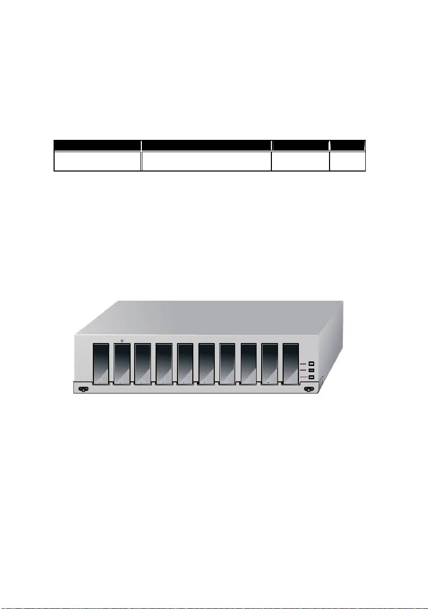
Converter Rack Model
Dual power units
3
4
1
5
6
7
1. Overview
The 19 -inch FVT -2000 Media Converter Rack is designed to accommodate 10 units of various type media
converter at a central location for multiple segments cross connectio n. IEEE802.3, 10Mbps Ethernet
supports for network connection such as 10Base-2, 10Base-T and 10Base-FL. IEEE802.3u, 100Mbps Fast
Ethernet supports 100Base-TX, 100Base -FX. The slide-in media converters are available for use at a 19 inch Media Converter Rack.
2. Model Description
Power Supply Configurations DC Output Slots
FVT-2000 Redundant Power,
with control unit
65W@+5V 10
The slide -in media converters and Converter Rack should be supplied only from the same source, both
Media Converters and Rack are built to match each other at dimensions, DC power jack, DC receptacle
and power safety.
3. Checklist
Before you start installing the Converter, verify that the package contains the following:
The FVT-2000 10/100Mbps Converter Chassis
AC Power Cord
Mounting Accessory (for 19" Rack Shelf)
This User's Manual
Please notify your sales representative immediately if any of the aforementioned items is missing or
damaged
Fig. 1 Front View of FVT-2000 19-inch Converter Chassis for Redundant Power Model
-2-
3 4 1 5 6 7 8 9 10
8 9 10
Media
Converter
Rack
Page 3
3 4 1 5 6 7 8 9 10
Media
Converter
Rack
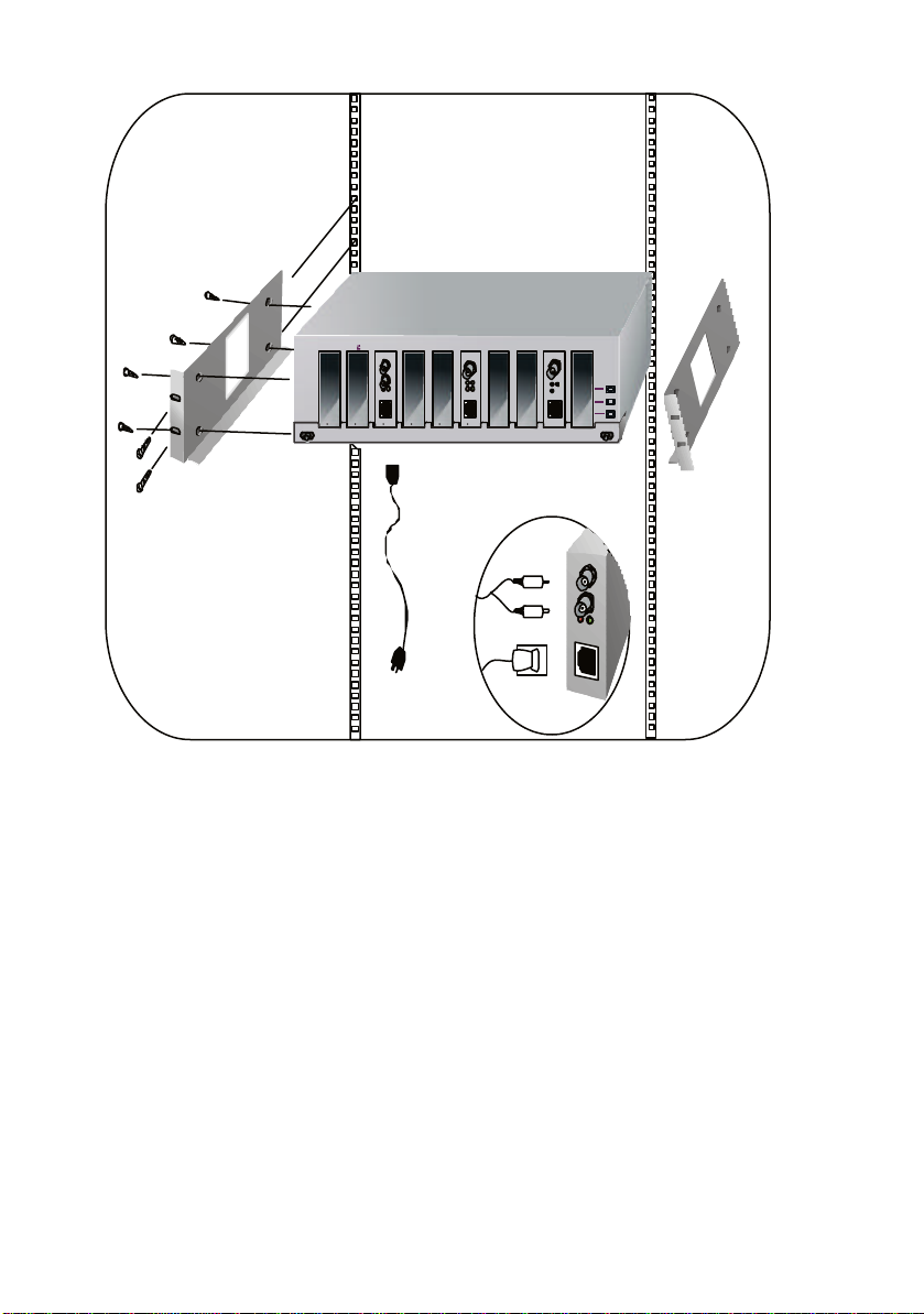
Fig. 2 Installing Media Converter Rack in FVT-2000 19-inch Wiring Closet Rails
-3-
Page 4
4. Installation
The Tx, Rx fiber
Slide switch "DTE" / "MPR" is on the
2.5mm
Each slot of 19
-
inch Converter
DC receptacle is 2.5mm
wide that conforms to the Media
A. Installing Media Converter Rack to a Wiring Closet Rack
⇒ Install four screws through mounting ears into each side
⇒ Locate Converter Rack at 19-inch mounting rails and screw up the front brackets
⇒ Set Main power switch at "OFF" position before connecting the power cord
B. Installing Media Converter to a Media Converter Rack
⇒ The slide -in Media Converters and Converter Rack should be supplied only from the same source,
both Media Conv erters and Rack are built to match each other at dimensions, DC power jack, DC
receptacle and power safety.
⇒ Turn off the 19" converter rack power
⇒ Verify the Media Converter is right for this Rack and locate +5VDC power jack on converter back,
carefully slide in and plug to match 19" rack slot +5V DC receptacle
⇒ Ensure that there is no activity in the network
⇒ Connect the media cable for network connection
⇒ Turn on the converter rack power, the Power LED will light up
Fiber Port: Attach the fiber cable.
TP Port: Attach UTP Cat. 3 or 5 cable to TP port
BNC Port: Attach T -Connector to BNC port and
Note:
1. Use the straight-through cable. Cable pin-outs for RJ-45 jack are 1, 2, 3, 6 to 1, 2, 3, 6
2. MPR(Default): To a Hub or Repeater
DTE : To a workstation or
NIC(Network Interface Card)
(DTE pin -outs are crossover on board ready)
3. Configure the MPR-DTE slide switch on the side panel for cable connection to a hub or
NIC(Network Interface Card)
cable must be paired at both ends
MPR : To a Hub or Repeater
DTE : To a workstation or NIC
side panel. Default: MPR
connect the RG-58 coaxial network.
Ensure the coaxial cable/segment is
terminated at both ends properly
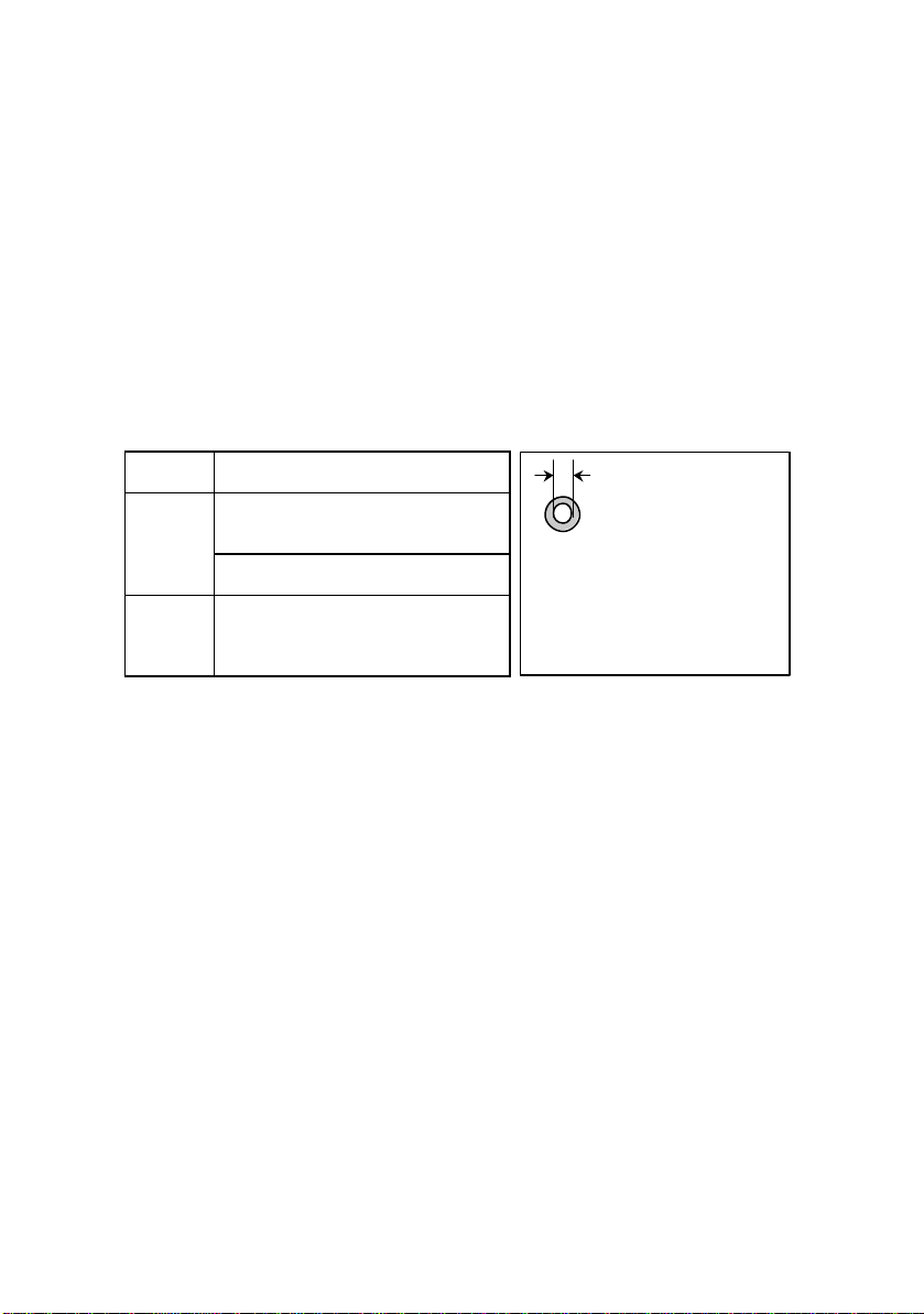
DC Receptacle 2.5mm
1A@+5V for each slot
Rack, its
Converter 2.5mm DC jack's
central post.
-4-
Page 5

5. 19-inch Media Converter Rack Technical Specifications
Converter Rack Model
, Dual power units
• Model No. :
Power Supply Configurations DC Output Slots
FVT-2000 Redundant Power
• Slot Capacity : 10 slots for slide -in converter
• LED Indicator:
Power A : Lit when power A is good
Power B : Lit when power B is good
Redundant: Lit when A and B are good Blink when either one failed
• Power Requirement:
AC Input:
Voltage 100∼240VAC
with control unit
65W@+5V 10
Per slot DC Power Output:1A@+5VDC
Per slot DC Power Plug: 2.5mm DC receptacle
• Ambient Temperature : 0° to 50°C
• Humidity : 5% to 90%
• Dimensions : 110(H) × 430(W) × 332(D) mm
• Weight : 8Kg
• Complies with FCC Part 15 Class A & CE Mark Approval
-5-
 Loading...