

Page 1

LevelOne
FSW-1610TX
FSW-2410TX
16/24 Port 10/100Mbps Fast Ethernet Switch
User’s Guide
Page 2
FCC Warning
This equipment has been tested and found to comply with
the regulations for a Class B digital device, pursuant to Part
15 of the FCC Rules. These limits are designed to provide
reasonable protection against harmful interference when the
equipment is operated in a commercial environment. This
equipment generates, uses, and can radiate radio frequency
energy and, if not installed and used in accordance with this
user’s guide, may cause harmful interference to radio
communications. Operation of this equipment in a
residential area is likely to cause harmful interference, in
which case the user will be required to correct the
interference at his own expense.
CE Mark Warning
This is a Class B product. In a domestic environment, this
product may cause radio interference, in which case the user
may be required to take adequate measures.
Page 3

TABLE OF C ONTENTS
ABOUT THIS GUIDE................................................................................3
PURPOSE....................................................................................................3
TERMS/USAGE ........................................................................................3
OVERVIEW OF THIS USER’S GUIDE ...............................................4
INTRODUCTION....................................................................................11
FAST ETHERNET TECHNOLOGY....................................................11
SWITCHING TECHNOLOGY ..............................................................12
FEATURES ...............................................................................................13
UNPACKING AND INSTAL LATION............................................... 15
UNPACKING............................................................................................15
INSTALLATION......................................................................................16
RACK MOUNTING................................................................................17
FRONT PANEL........................................................................................19
REAR PANEL..........................................................................................19
LED INDICATORS................................................................................21
CONNECTING THE SWITCH ...........................................................22
PC TO SWITCH......................................................................................22
HUB TO SWITCH...................................................................................22
A. 10BASE-T Hub..........................................................................23
B. 100BASE-TX Hub....................................................................23
SWITCH TO SWITCH (OTHER DEVICES) ......................................24
A. Using straight cable .................................................................... 24
i
Page 4

B. Using crossover cable................................................................ 24
PORT SPEED & DUPLEX MODE.....................................................25
TECHNICAL SPECIFICATIONS ......................................................26
ii
Page 5

A BOUT THIS GUIDE
Congratulations on your purchase of the LevelOne FSW1610/2410TFX 16/24P ort 10/100Mbps Fast Ethernet Switch.
This device integrates 100Mbps Fast Ethernet and 10Mbps
Ethernet network capabilities in a highly flexible package.
Purpose
This guide discusses how to install your LevelOne 16/24Port
10/100Mbps Fast Ethernet Switch.
Terms/Usage
In this guide, the term “Switch” (first letter upper case)
refers to your LevelOne 16/24P ort 10/100Mbps Fast
Ethernet Switch, and ”switch” (first letter lower case) refers
to other Ethernet switches.
This guide provides the information you need to install and
configure the following models of the Switch:
§ LevelOne FSW -1610TX 16Port 10/100Mbps Fast
Ethernet Switch
§ LevelOne FSW -2410TX 24Port 10/100Mbps Fast
Ethernet Switch
The functionality of three units is identical, except for the
number of ports. Where appropriate, differences between the
two units are noted.
3
Page 6

Overview of this User’s Guide
Chapter 1, Introduction. Describes the Switch and its features.
Chapter 2, Unpacking and Installation. Helps you get started with
the basic installation of the Switch.
Chapter 3, Identifying External Components. Describes the front
panel, rear panel and LED indicators of the Switch.
Chapter 4, Connecting the Switch. Tells how you can connect the
Switch to your Ethernet network.
Appendix A, Technical Specifications. Lists the technical
(general, physical and environmental, and performance)
specifications of the Switch.
Appendix B, RJ-45 Pin Specification. Describes the RJ-45
receptacle/connector and the straight and crossover cable
connector.
4
Page 7

INTRODUCTION
This chapter describes the features of the Switch and some
background information about Ethernet/Fast Ethernet
switching technology.
Fast Ethernet Technology
The growing importance of LANs and the increasing
complexity of desktop computing applications are fueling the
need for high performance networks. A number of high-speed
LAN technologies have been proposed to provide greater
bandwidth and improve client/server response times. Among
them, 100BASE-T (Fast Ethernet) provides a non -disruptive,
smooth evolution from the current 10BASE-T technology.
The non-disruptive and smooth evolution nature, and the
dominating potential market base, virtually guarantee cost
effective and high performance Fast Ethernet solutions in
the years to come.
100Mbps Fast Ethernet is a new standard specified by the
IEEE 802.3 LAN committee. It is an extension of the
10Mbps Ethernet standard with the ability to transmit and
receive data at 100Mbps, while maintaining the CSMA/CD
Ethernet protocol. Since the 100Mbps Fast Ethernet is
compatible with all other 10Mbps Ethernet environments, it
provides a straightforward upgrade and takes advantage of
the existing investment in hardware, software, and
personnel training.
11
Page 8

Switching Technology
Another approach to pushing beyond the limits of Ethernet
technology is the development of switching technology. A
switch bridge Ethernet packets at the MAC address level of
the Ethernet protocol transmitting among connected
Ethernet or Fast Ethernet LAN segments.
Switching is a cost-effective way of increasing the total
network capacity available to users on a local area network.
A switch increases capacity and decreases network loading
by dividing a local area network into different segments,
which don’t compete with each other for network
transmission capacity.
The switch acts as a high-speed selective bridge between the
individual segments. The switch, without interfering with
any other segments, automatically forwards traffic that
needs to go from one segment to another. By doing this the
total network capacity is multiplied, while still maintaining
the same network cabling and adapter cards.
For Fast Ethernet networks, a switch is an effective way of
eliminating problems of chaining hubs beyond the “tworepeater limit.” A switch can be used to split parts of the
network into different collision domains, making it possible
to expand your Fast Ethernet network beyond the 205 -meter
network diameter limit for 100BASE-TX networks. Switches
supporting both traditional 10Mbps Ethernet and 100Mbps
Fast Ethernet are also ideal for bridging between the
existing 10Mbps networks and the new 100Mbps networks.
8
Page 9

Switching LAN technology is a marked improvement over
the previous generation of network bridges, which were
characterized by higher latencies. Routers have also been
used to segment local area networks, but the cost of a router,
the setup and maintenance required make routers relatively
impractical. Today switches are an ideal solution to most
kinds of local area network congestion problems.
Features
The Switches were designed for easy installation and high
performance in an environment where traffic on the network
and the number of user increase continuously.
The Switches with its rack size is specifically designed for
middle to large workgroups. These Switches provide
immediate access to a rapidly growing network through a
wide range of user -reliable functions.
The Switches are ideal for deployment with multiple highspeed servers for shared bandwidth 10Mbps or 100Mbps
workgroups. With the highest bandwidth 200Mbps (100Mbps
full-duplex mode), any port can provide workstations with a
congestion-free data pipe for simultaneous access to the
server.
The Switches are expandable by cascading two or more
switches together. As all ports support 200Mbps, the
Switches can be cascaded from any port and to any number
of switches.
The Switches are a perfect choice for site planning to
13
Page 10

upgrade to Fast Ethernet in the future. Ethernet
workgroups can connect to the Switches now, and change
adapters and hu bs anytime later without needing to change
the Switches or reconfigure the network.
The Switches combine dynamic memory allocation with
store-and-forward switching to ensure that the buffer is
effectively allocated for each port, while controlling the data
flow between the transmit and receive nodes to guarantee
against all possible packet loss.
The Switches are an unmanaged 10/100 Fast Ethernet
Switch offering solutions in accelerating small Ethernet
workgroup bandwidth. Other key features are:
Auto-MDI function supports automatic MDI/MDIX crossover
detection function gives true ‘plug and play’ capability without the
need of confusing crossover cables or crossover ports.
Store and forward switching scheme capability. As the result of
complete frame checking and error frame filtering, this scheme
prevents error packages from transmitting among segments.
NWay Auto-negotiation for any port. This allows for auto-sensing
of speed (10/100Mbps) thereby providing you with automatic and
flexible solutions in your network connections.
Flow control for any port. This minimizes dropped packets by
sending out col lision signals when the port’s receiving buffer is
full. Note that flow control is only available in half duplex mode.
Data forwarding rate per port is at wire-speed for 100Mbps speed.
Data forwarding rate per port is at wire-speed for 10Mbps speed.
Data filtering rate eliminates all error packets, runts, etc., per port
8
Page 11

15
at wire-speed for 100Mbps speed.
Data filtering rate eliminates all error packets, runts, etc., per port
at wire-speed for 10Mbps speed.
Up to 8K active MAC address entry table with self-learning and
table-aging for 16-port model and 24-port model.
512KB RAM buffer per device for 16-port model and 24-port
model
U NPACKING AND INSTALLATION
This chapter provides unpacking and setup information for
the Switches.
Unpacking
Open the shipping cartons of the Switch and carefully
unpacks its contents. The carton should contain the
following items:
One the LevelOne FSW-1610/2410TFX 16/24Port 10/100Mbps
Fast Ethernet Switch
One AC power cord, suitable for your area’s electrical power
connections
Four rubber feet to be used for shock cushioning
Screws and two mounting brackets
This User’s Guide
If any item is found missing or damaged, please contact your
local reseller for replacement.
Page 12

Installation
The site where you install the hub stack may greatly affect
its performance. When installing, consider the following
pointers:
Install the Switch in a fairly cool and dry place. See Appendix B
for the acceptable temperature and humidity operating ranges.
Install the Switch in a site free from strong electromagnetic field
generators (such as motors), vibration, dust, and direct exposure to
sunlight.
Leave at least 10cm of space at the front and rear of the hub for
ventilation.
Install the Switch on a sturdy, level surface that can support its
weight, or in an EIA standard-size equipment rack. For
information on rack installation, see the next section, Rack
Mounting.
When installing the Switch on a level surface, attach the
rubber feet to the bottom of each device. The rubber feet
cushion the hub and protect the hub case from scratching.
8
Page 13
17
Rack Mounting
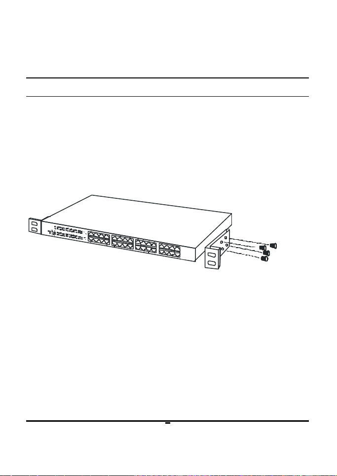
The switch can be mounted in an EIA standard-size, 19 -inch
rack, which can be placed in a wiring closet with other
equipment. Attach the mounting brackets at the switch’s
front panel (one on each side), and secure them with the
provided screws.
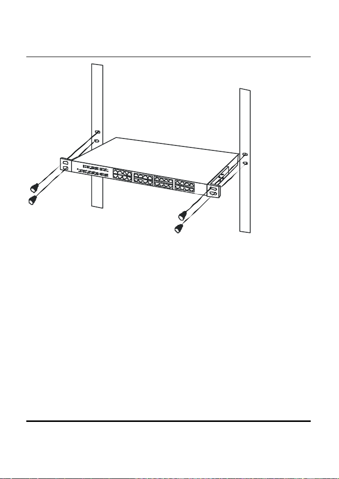
Then, use screws provided with the equipment rack to mount
each switch in the rack.
Page 14
Identifying External Components
This section identifies all the major external components of
the switch. Both the front and rear panels are shown,
followed by a description of each panel feature. The indicator
panel is described in detail in the next chapter.
8
Page 15
19
Front Panel
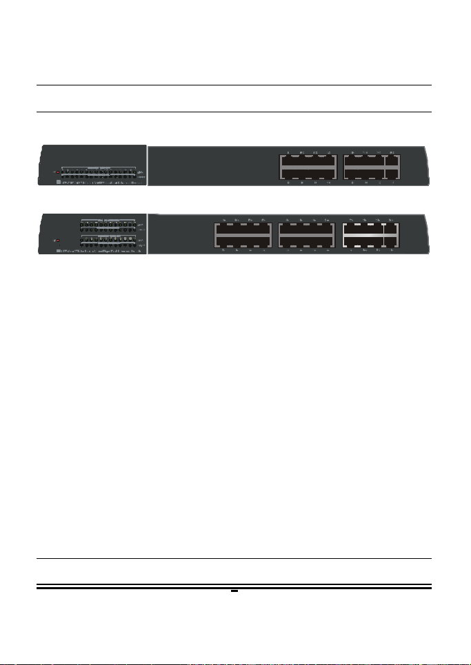
The figure below shows the front panels of the switches.
16-port 10/100M Fast Ethernet Switch
24-port 10/100M Fast Ethernet Switch
LED Indicator Panel
Refer to the next chapter for detailed information
about each of the switch’s LED indicators.
l Auto-MDI/MDIX Jacks:
These jacks supports automatic MDI/MDIX crossover detection
function gives true ‘plug and play’ capability without the need
of confusing crossover cables or crossover ports.
With the Auto-MDI/MDIX function, you just need to plug-in
the network cable to the hub directly and no need to care if the
end node is NIC (Network Interface Card) or switches and hubs.
Rear Panel
Page 16
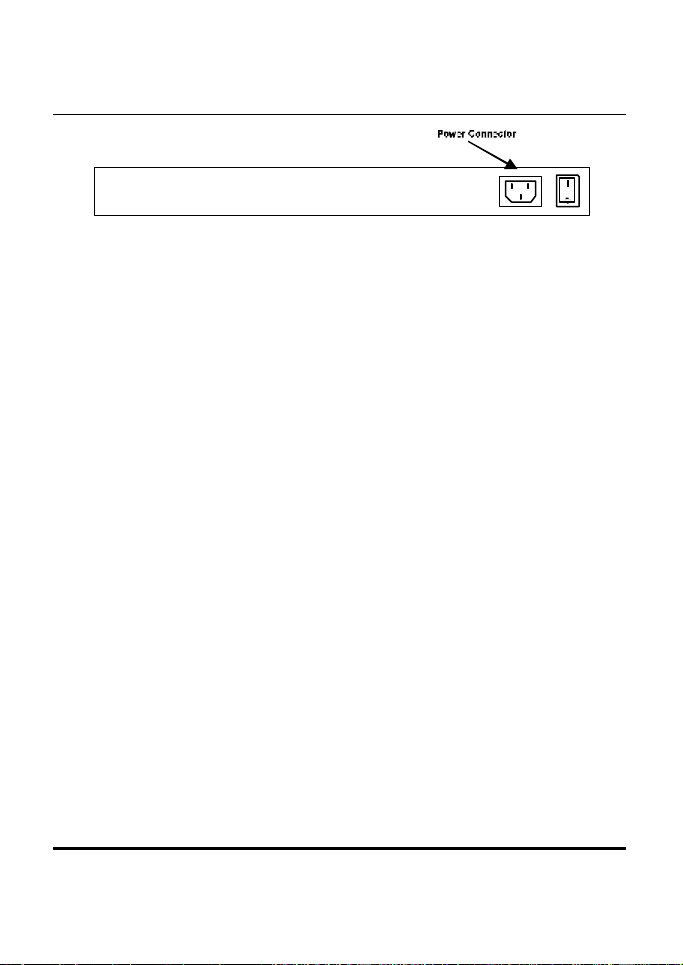
LevelOne 16/24 Port 10/100Mbps Fast Ethernet Switch
AC Power Connector:
For the power cord.
8
Page 17

LED Indicators
Power Indicator (PWR)
This LED lights green when the switch is receiving current; if not,
power is off.
100M Link/Activity, 10M Link/Activity
(100M LINK/ACT(green), 10LINK/ACT(yellow))
This indicator light green when the port is connected to a 100Mbps
Fast Ethernet station, if the indicator blinking green will be
transmitting or received data on the 100Mbps network. Otherwise,
if the indicator light amber when the port is connected to a
10Mbps Ethernet station, if the indicator blinking amber will be
transmitting or received data on the 10Mbps network.
Full/Half Duplex, 10/100M Collision
(10/100M FDX(green),10/100M COL (blinking))
This LED indicator lights green when a respective port is
in full duplex (FDX) mode. Otherwise, it is OFF for half
duplex (HDX) operations. It blinking green when
collisions are occurring on the respective port.
21
Page 18

C ONNECTING THE SWITCH
This chapter describes how to connect the Switch to your
Fast Ethernet network.
PC to Switch
A PC can be connected to the Switch via a two-pair Category
3, 4, 5 UTP/STP straight cable. The PC (equipped with a RJ45 10/100Mbps phone jack) should be connected to any of the
16 ports (1x - 16x) for the 16Port model, 24 ports (1x - 24x)
for the 24Port model
The LED indicators for PC connection dependent on the LAN
card capabilities. If LED indicators are not light after
making a proper connection, check the PC LAN card, the
cable, the Switch conditions and connections.
The following are LED indicator possibilities for a PC to
Switch connection:
1. The “100M LINK/ACT, 10M LINK/ACT” LED
indicator light green for hookup to 100Mbps speed or
light amber for hookup to 10Mbps speed.
2. The “10/100M FDX, 10/100M COL LED” indicator
depends upon LAN card capabilities for full-duplex or
half-duplex.
Hub to Switch
A hub (10 or 100BASE-TX) can be connected to the Switch
24
Page 19

via a two-pair Category 3, 4, 5 UTP/STP cable. The
connection is accomplished from the hub uplink (MDI-II)
port to any port of the Switch (MDI-X) ports.
A. 10BASE-T Hub
For a 10BASE-T hub, the Switch LED indicators should light
up as the following:
“10/100M FDX, 10/100M COL” LED indicator is OFF.
“100M LINK/ACT, 10LINK/ACT” LED indicator is light amber.
B. 100BASE-TX Hub
For a 100BASE-TX hub, the Switch LED indicators should
light up as the following:
“10/100M FDX, 10/100M COL” LED indicator is OFF.
“100M LINK/ACT, 10M LINK/ACT” LED indicator is light
green.
23
Page 20

Switch to Switch (other devices)
The Switch can be connected to another switch or other
devices (routers, bridges, etc.) via a two -pair Category 3, 4, 5
UTP/STP straight or crossover cable.
A. Using straight cable
When using straight cable, this is done from the uplink
(MDI-II) port of other Switch to any of the 10Mbps or
100Mbps (AUTO MDI-X) port of FSW-1610TX/ 2409TFX.
B. Using crossover cable
When using crossover cable, this is done from any (MDI-X)
port of the Switch (Switch A) to any of the 10Mbps, 100Mbps
(AUTO MDI-X) port of FSW-1610TX/ 2409TFX.
1. The “100M LINK/ACT, 10M LINK/ACT” LED
indicator light green for hookup to 100Mbps speed or
light amber for hookup to 10Mbps speed.
2. The “10/100M FDX, 10/100M COL” LED indicator
depends upon LAN card capabilities for full-duplex or
half-duplex
24
Page 21

Port Speed & Duplex Mode
After plugging the selected cable to a specific port, the
system uses auto -negotiation to determine the transmission
mode for any new twisted-pair connection:
If the attached device does not support autonegotiation or has auto-negotiation disabled, an auto-
sensing process is initiated to select the speed and set the
duplex mode to half-duplex.
23
Page 22
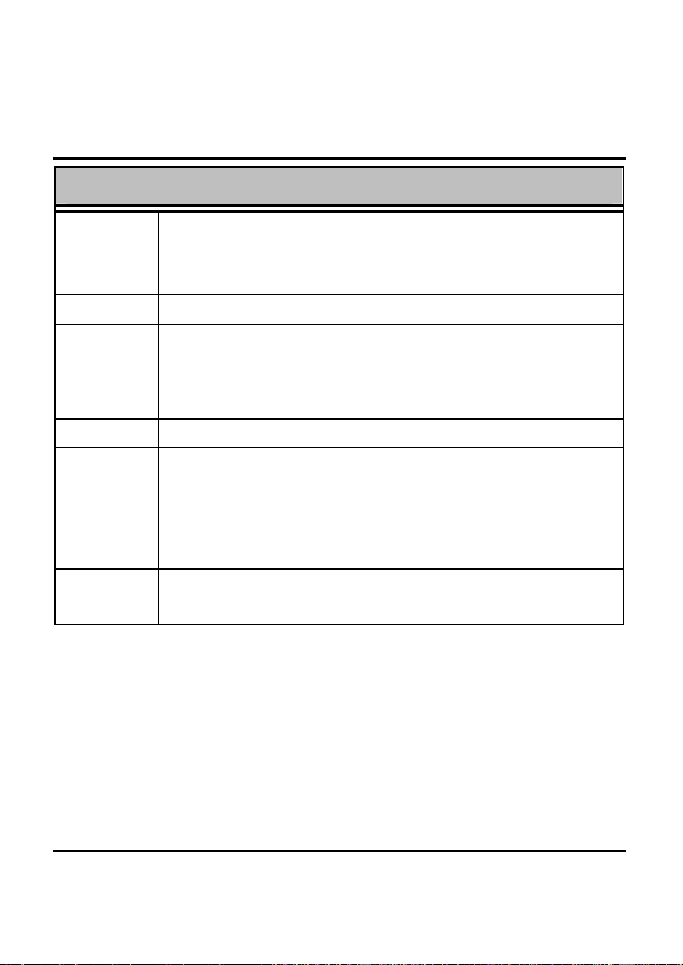
Ethernet: 10Mbps (half duplex)
T ECHNICAL SPECIFICATIONS
General
Standards IEEE 802.3 10Base-T Ethernet
IEEE 802.3u 100 Base-TX Fast Ethernet
ANSI/IEEE 802.3 NWay auto-negotiation
Protocol CSMA/CD
Data
Transfer
Rate
Topology Star
Network
Cables
Number of
Ports
Fast Ethernet: 100Mbps (half duplex)
10BASET: 2-pair UTP Cat. 3,4,5 (100 m), EIA/TIA- 568
100BASE-TX: 2-pair UTP Cat. 5 (100 m), EIA/TIA-568 100-
100BASE-FX: 62.5/125 micron multimode fiber optic (2km)
16-port: 16 x 10/100Mbps NWay ports
24-port: 24 x 10/100Mbps NWay ports
20Mbps (full duplex)
200Mbps (full duplex)
100-ohm STP (100 m)
ohm STP (100 m)
26
Page 23
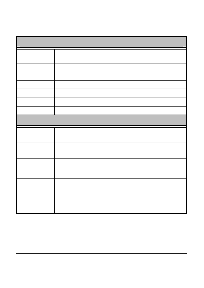
Physical and Environmental
AC inputs 100 to 240 VAC, 50 or 60 Hz internal universal power
Power
Consumption
Temperature Operating: 0° ~ 50° C, Storage: -10° ~ 70° C
Humidity Operating: 10% ~ 90%, Storage: 5% ~ 90%
Dimensions 440 x 200 x 44 mm (W x H x D)
EMI: FCC Class A, CE Mark , VCCI Class A
supply
7 watts. (max.) for FSW-1610TX
13.2 watts. (max.) for FSW-2410TX
Performance
Transmission
Method:
RAM Buffer:
Filtering
Address
Table:
Packet
Filtering/For
warding Rate:
MAC Address
Learning:
Store-and-forward
16-port: 512K bytes per device
24-port: 512K bytes per device
16-port: Up to 8K entries per device
24-port: Up to 8K entries per device
10Mbps Ethernet: 14,880/pps
100Mbps Fast Ethernet: 148,800/pps
Automatic update
25
 Loading...