

Page 1

FSW-0802/1201TX
8/12 Ports Nway Switch
User’s Manual
53100000300C
DOC:FSWM801
Page 2

Page 3

FCC Warning
This device has been tested and found to comply with limits for a Class A
digital device, pursuant to Part 15 of the FCC Rules. These limits are
designed to provide reasonable protection against harmful interference when
the equipment is operated in a commercial environment. This equipment
generates, uses and can radiate radio frequency energy and, if not installed
and used in accordance with the user ’s manual, may cause interference in
which case user will be required to correct the interference at his own
expense.
CE Mark Warning
This is a Class A product. In a domestic environment, this product may
cause radio interference in which case the user may be required to take
adequate measures.
Page 4

Page 5

Table of Contents
CHAPTER 1 INTRODUCTION..................................................... 1-1
About Nway Ethernet Switch FSW-0802/1201TX ...................... 1-1
Key Features ............................................................................................... 1-2
Mini-Console Highlights ............................................................................. 1-3
Unit Overview............................................................................................. 1-3
Front Panel Layout...............................................................................1-3
Mini-Console .............................................................................................. 1-4
Rear Panel Layout....................................................................................... 1-5
CHAPTER 2 INSTALLATION ...................................................... 2-1
Using Rack Mounting .................................................................................. 2-1
Connecting Other Network Devices............................................................. 2-2
Connecting Workstations....................................................................2-2
Connecting Ethernet Hubs...................................................................2-3
Connecting Fast Ethernet Hubs...........................................................2-4
CHAPTER 3 MINI-CONSOLE...................................................... 3-1
Message Zone ............................................................................................. 3-2
Observing Basic Port Information ................................................................ 3-2
Port Indicator Definitions ............................................................................. 3-3
Console Keys .............................................................................................. 3-4
Power On Self-Test..............................................................................3-4
Menu Tree .................................................................................................. 3-4
Exiting the Menu Tree ................................................................................. 3-7
Observing Network Traffic .......................................................................... 3-7
Observing Collision Level........................................................................... 3-8
Monitoring Ports Status ............................................................................... 3-8
Monitoring Port Detail Information.............................................................3-10
Optimizing Network Performance...............................................................3-12
Configuring Ports.......................................................................................3-13
VLANs ......................................................................................................3-15
Selecting a Buffer Mode .............................................................................3-15
FSW-1201TX Buffer Groups............................................................3-16
FSW-0802TX Buffer Groups............................................................3-16
Unit Configuration.....................................................................................3-17
Broadcast Storm Protection ...............................................................3-17
Loop Isolation....................................................................................3-18
Lock the Console........................................................................................3-18
Unlock the Console ....................................................................................3-19
Secure the Switch .......................................................................................3-19
Page 6

Set Password......................................................................................3-19
Cancel Password..............................................................................3-200
In Case You Forget the Password...................................................3-200
Back Door Password ................................................................................3-200
Restart the Switch.....................................................................................3-200
Restore System Setting .............................................................................3-211
About The Switch.....................................................................................3-222
System Info......................................................................................3-223
APPENDIX A TECHNICAL SPECIFICATIONS............................ A-1
APPENDIX B ERROR MESSAGES ............................................B-1
APPENDIX C MENU TREE.........................................................C-1
Page 7
Introduction
1-1
Chapter 1
Introduction
About Nway Switch
FSW-0802/1201TX
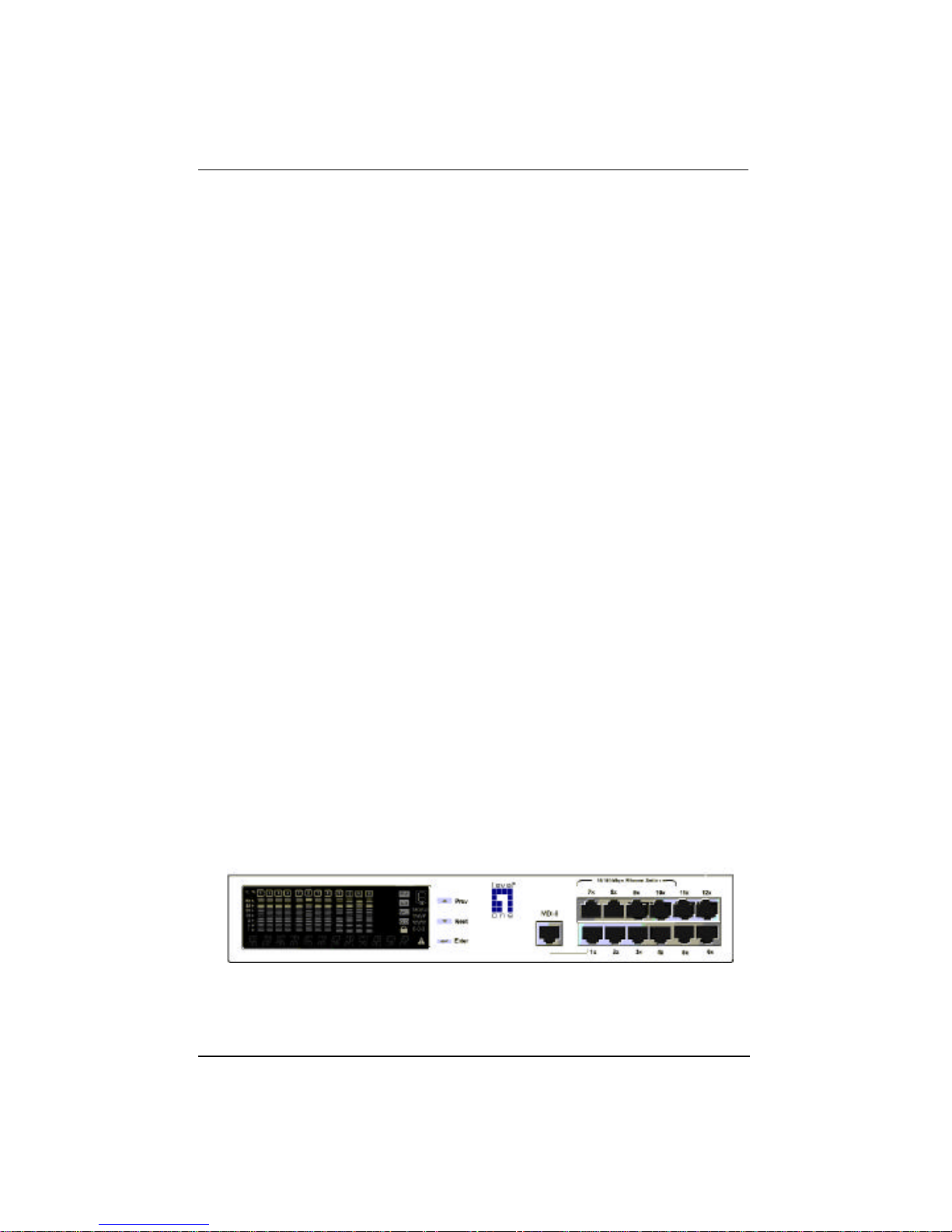
The Nway Ethernet Switch FSW-0802/1201TX is a compact switch designed
to meet the requirement for today ’s growing network. It introduces the
management function with very low cost while maintaining high
performance in networking. Users can monitor the Utilization, Collision ratio,
Statistic Counters, Port Status and configure the switch.
Figure 1.1 Nway Ethernet Switch FSW-1201TX
Page 8
Introduction
1-2
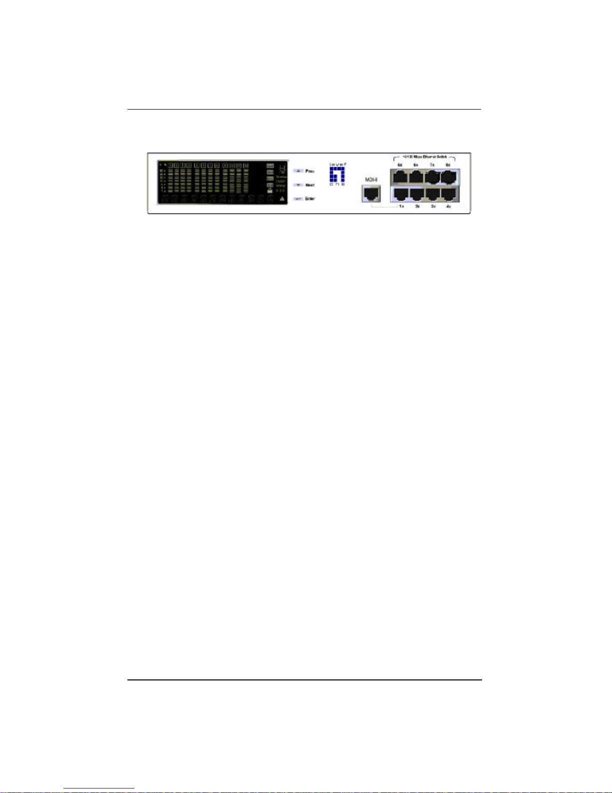
Figure 1.2 Nway Ethernet Switch FSW-0802TX
The Nway Ethernet Switch FSW-0802/1201TX provides 8/12 10/100 Mbps
ports, one shared Uplink port and one shared MII port for flexible backbone
integration.
The Nway Ethernet Switch FSW-0802/1201TX is a plug and play Network
Switching Device. No settings need to be made to get the network up and
running.
Key Features
Designed for high-performance, versatility, and cost-effectiveness, the
Nway Ethernet Switch FSW-0802/1201TX provides the following key
features:
• One Uplink port shared.
• 8/12 10/100 Mbps Ports (auto negotiate, full duplex, fragment free,
fast store forward modes)
• One MII port (Medium Independent Interface) shared with port 5 for
model FSW-0802TX and port 7 for model FSW-1201TX.
• Smart Mini-Console operation for easy configuration and monitoring
status.
• Three modes of smart buffer allocation to optimize your network; Low,
Medium, High. You can assign a larger buffer to the heavily used
ports connected to a server and a smaller buffer to less important
terminals.
• Broadcast Storm Protection
Page 9
Introduction
1-3
• Flow control to prevent packet loss
• Self diagnostic watch dog protection
• Affordable smart switch to replace dump switch.
• Loop Detection
• Multiple VLANs – any port can join any VLAN
Mini-Console Highlights
• Device and port configuration, management & statistics monitoring
through an easy to use menu.
• Traffic utilization and collision ratio indication on all the ports.
• Status monitoring such as; speed, duplex mode, switching mode on all
ports.
• Console keys to carry out all console command functions.
• Password locking of the Console to prevent unauthorized access.
Unit Overview
The Nway Ethernet Switch FSW-0802/1201TX was designed for small to
medium size workgroups.
Front Panel Layout
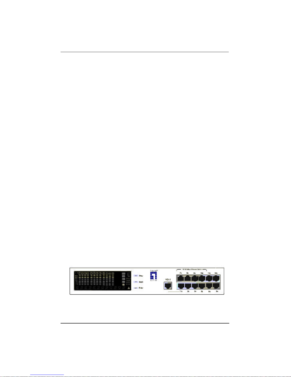
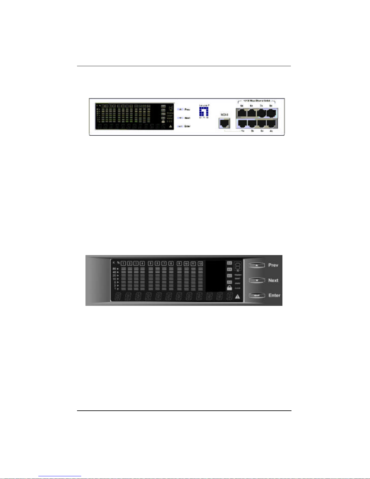
The front panel supports the Mini-Console, Console keys and ports.
Nway Ethernet Switch FSW-1201TX Front Panel
Page 10
Introduction
1-4
Figure 1.3 Nway Ethernet Switch FSW-0802TX Front Panel
Mini-Console
The Mini-Console is a high definition display and Console keys that enable
users to easily monitor and configure the system. The Mini-Console provides
watch diagnostic functions, including port settings, status monitoring, traffic
utilization, collision, and error rate.
Figure 1.4 Mini-Console
With the build-in Console Keys, users are able to monitor and configure all
the ports simultaneously or individually.
Page 11
Introduction
1-5
Rear Panel Layout
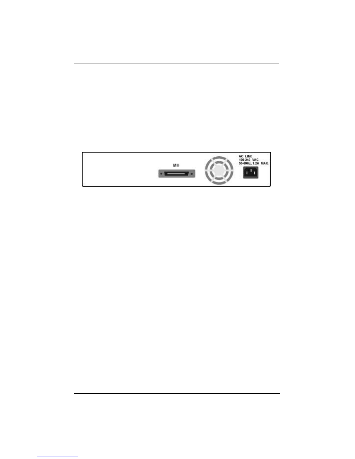
The MII port, power socket and fan are located on the rear panel.
Note: The MII port is not hot-pluggable. FSW-0802/1201TX will detect an
MII connection only during the system start.
Figure 1.5 Rear Panel
Page 12

Page 13
Installation
2-1
Chapter 2
Installation
Using Rack Mounting
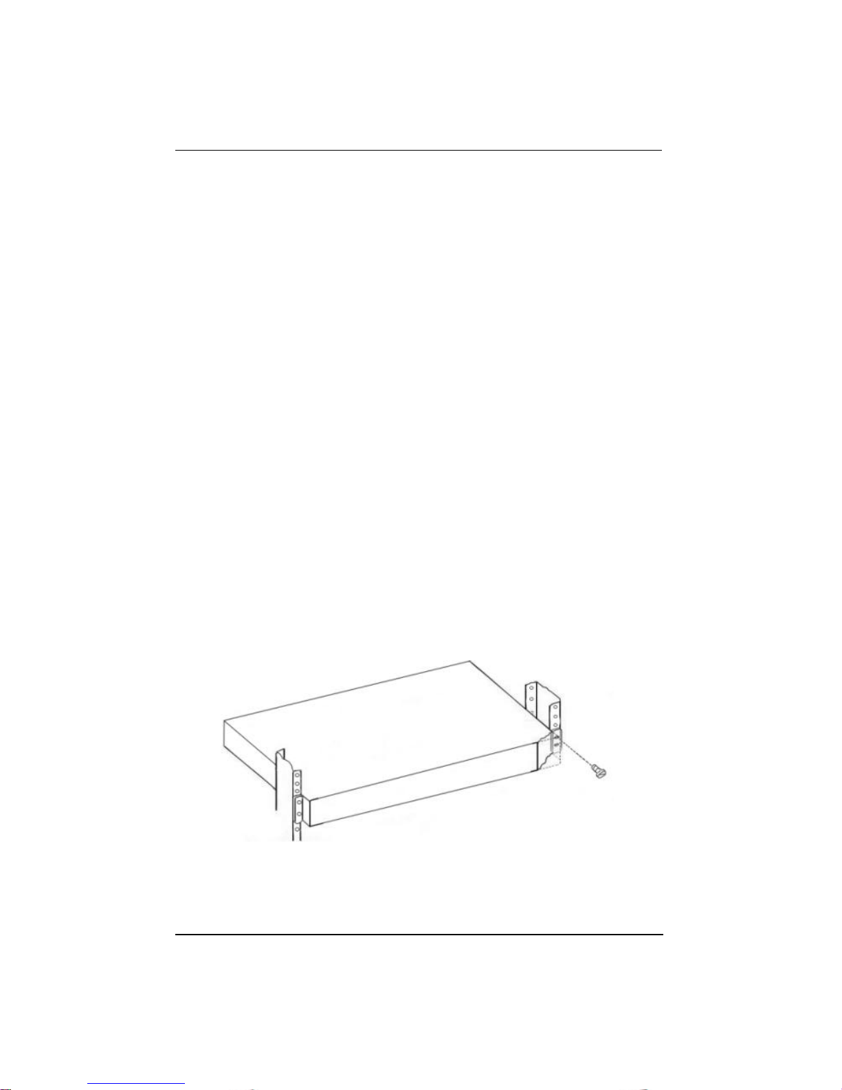
Optional rack mounting brackets are available to mount hubs in standard EIA
19-inch racks.
Align the mounting brackets on the sides of the unit with the slit over the
holes. Secure the screws tightly to fix the brackets to the device. Then, place
the device into the 19” rack and fix it properly. Please ensure that the
ventilation holes do not get blocked.
.
Figure 2.1 Rack Mounting
Page 14

Installation
2-2
Connecting Other Network
Devices
Connecting Workstations
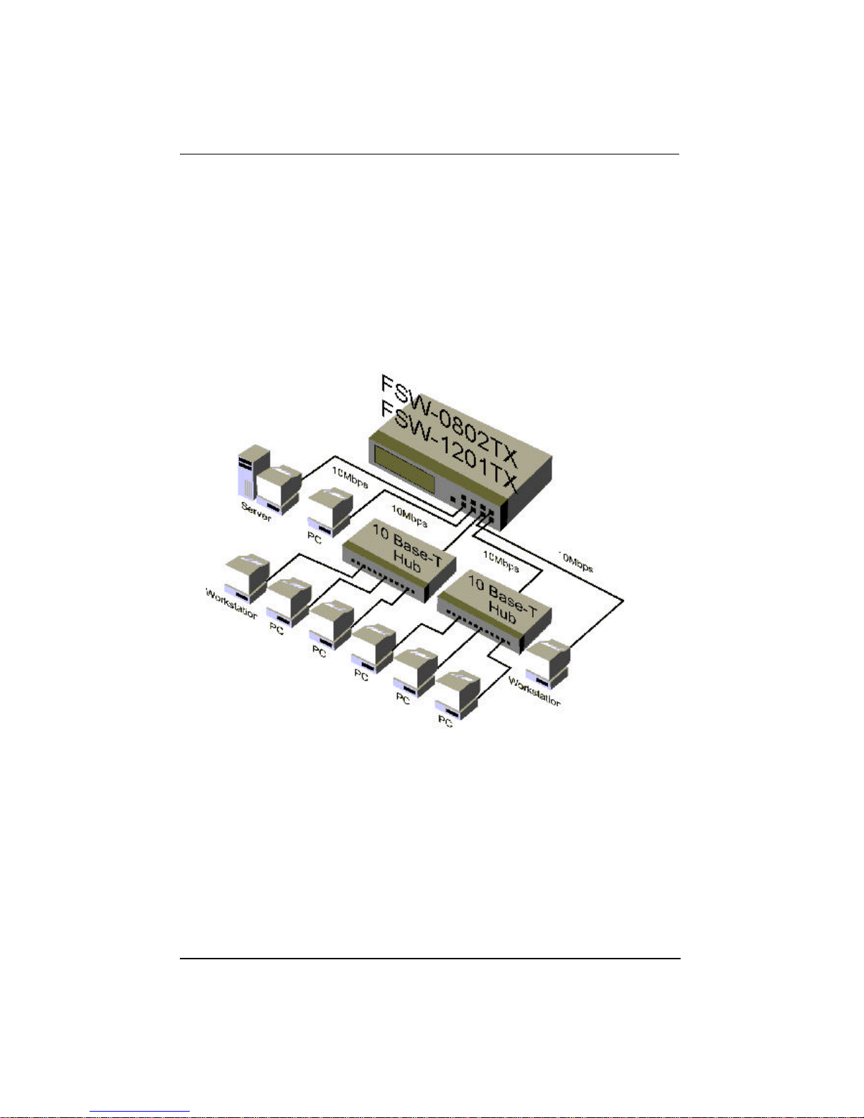
Figure 2.3 shows the Nway Ethernet Switch FSW-0802/1201TX in a client
server topology.
Figure 2.1 Connecting Workstations.
Page 15
Installation
2-3
Connecting Ethernet Hubs
This example shows how 10M hubs can be connected to the Nway Ethernet
Switch FSW-0802/1201TX to form a larger network.
Figure 2.2 Connecting Ethernet Hubs.
Page 16
Installation
2-4
Connecting Fast Ethernet Hubs
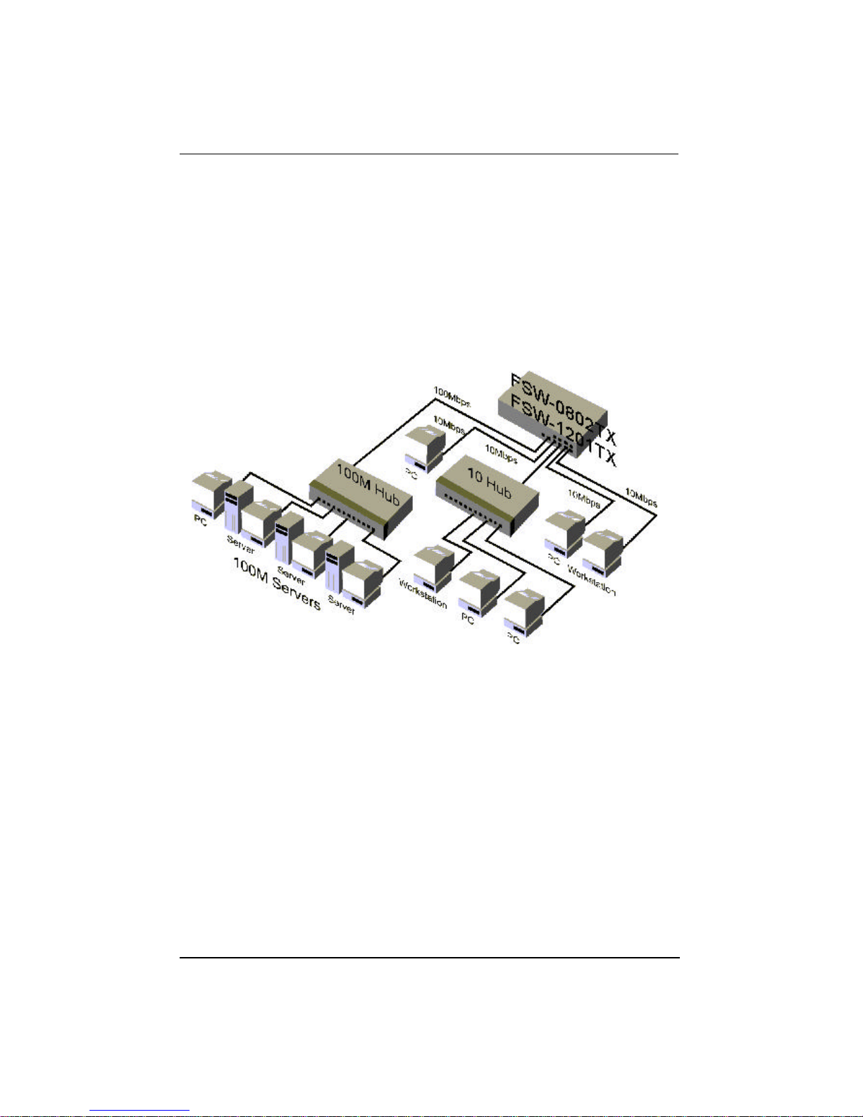
This example shows how 10 /100 M hubs can be connected to the Nway
Ethernet Switch FSW-0802/1201TX to form a larger network.
Figure 2.3 Connecting Fast Ethernet Hubs.
Page 17
Mini Console
3-1
Chapter 3
Mini-Console
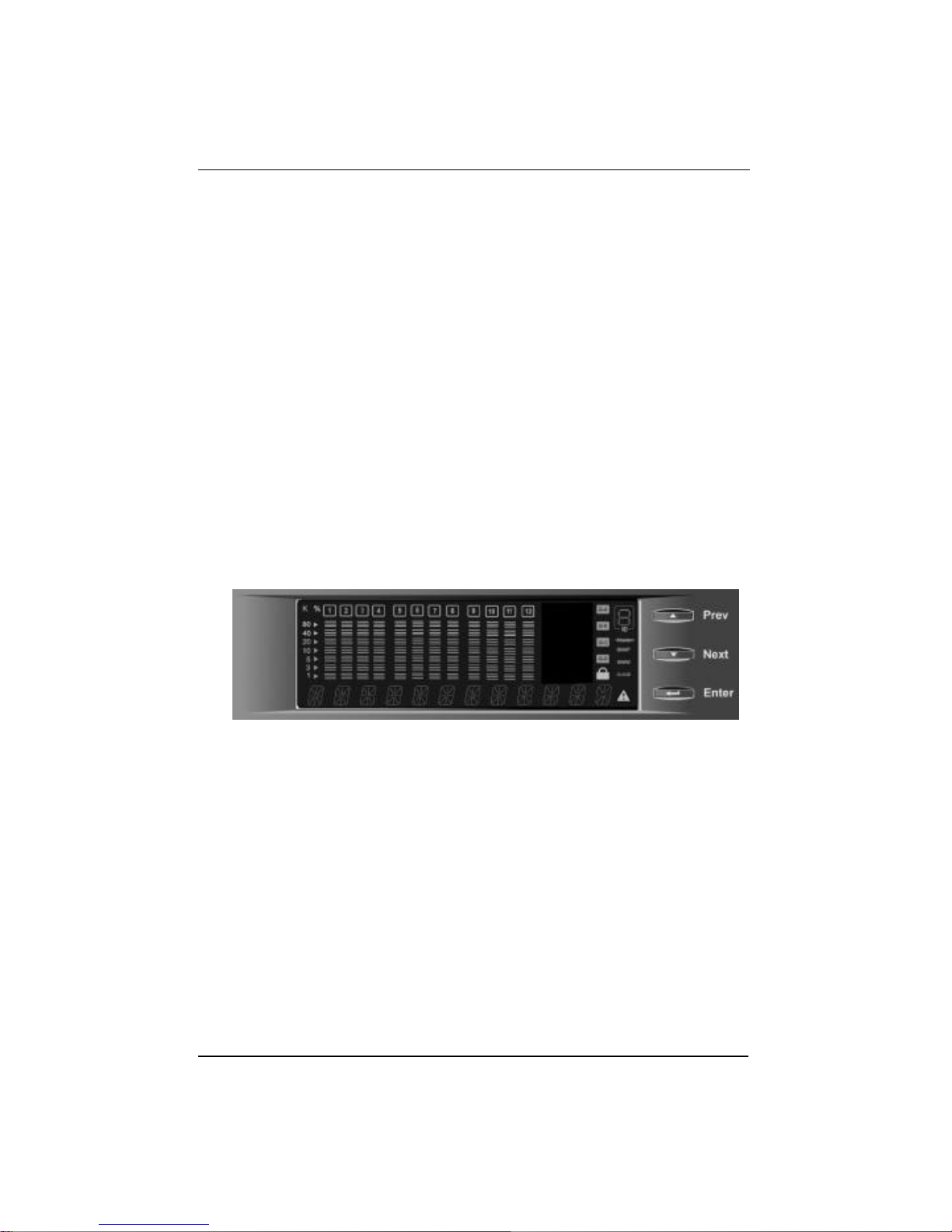
The Mini-Console is similar to the following illustration. Becoming familiar
with and understanding the functions of the Mini-Console will easily enable
the user to utilize the full power of the FSW-0802/1201TX and create an
efficient network.
Figure 3.1 Mini-Console
Page 18
Mini Console
3-2
Message Zone
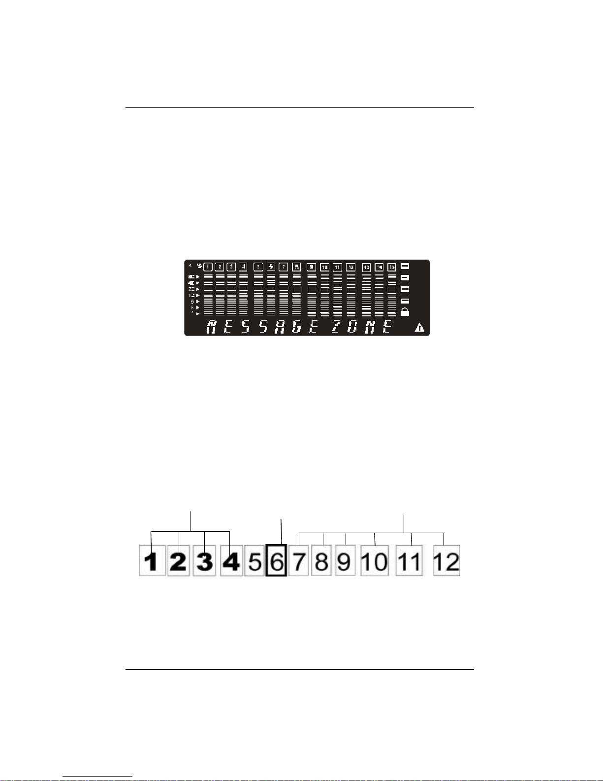
The Message Zone displays the menu items in the menu tree. The large
alphanumeric characters are easy to read and are an important navigational
tool.
Figure 3.2 Message Zone
Observing Basic Port
Information
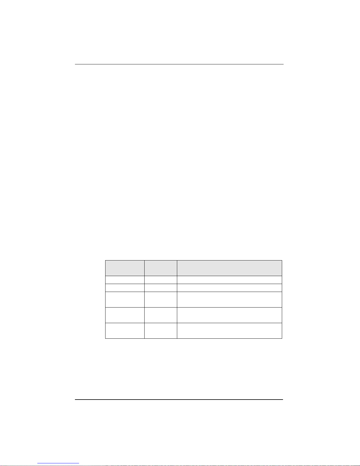
The basic port information, such as link up, link down, transmit/receive
activity, enabled/disabled as well as auto partition can be easily spotted
through the Port Indicators located in the first row of the Mini-Console.
Figure 3.3 Port Indicators
Port Indicators: Showing the activity of ports such as link up, link down,
Tx/Rx, enabled or disabled.
Link Up Ports
Partitioned
Port
Link Down Ports
Page 19
Mini Console
3-3
The Port Indicator shows the ports that are linked up by
intensifying the light for the ports that are available. The
example above, Fig 3.3 shows ports 1~4, are linked up (or
available) and port 6 is partitioned.
While the ports are receiving or transmitting data, the port’s
number will be flashing.
When a port is disabled by the administrator, an amber
frame around the port number will be turned on.
If the outline is blinking, it means it has been partitioned
automatically due to some error condition such as a loop or
broadcast storm that has been detected.
Port Indicator Definitions
The following table summarizes the definition of the port indicators.
Port
Number
Frame Indicates
Slightly on Off Port is available but link is down.
On Off Port is available and link is up.
Flashing Off Link is up and
transmitting/receiving data.
On On The port is link up and disabled by
the administrator.
On Blinking The port is link up and partitioned
by machine itself due to errors.
Table 3.1 Port Indicators
Page 20

Mini Console
3-4
Console Keys
Use the Console Keys to navigate the Menu Tree and to make selections.
The Previous Key and the Next Key are used to cycle through the menus
and the Enter Key is used to select the displayed menu item or set the default.
Power On Self-Test
When the systems power is turned on the system runs an EEPROM TEST
and a PCI TEST, Self-Test. When the Self-Test is complete, the Mode
Indicator will display the current mode, the first to be displayed is
UTILIZATION. To display other main menu items press the Next/Prev key.
Menu Tree
There are up to four levels in the Menu Tree; main menu, sub menu and up to
two configuration levels. To move from a main menu item to its sub menus,
press the Enter console key while the main menu item is displayed in the
Mini-Console. Press the Next or Prev key to cycle through all the items in
each menu level and press Enter to move to the next menu level or make a
selection. Utilization and Collision have no sub menus. Configuration items
with an “*” prefix are the system defaults.
UTILIZATION Utilization across all ports is displayed.
COLLISION Collision across all ports is displayed.
Page 21

Mini Console
3-5
STATISTICS PORT 1~12 Rx FRAMES
Rx OCTETS
Rx-ALIGN ERR
Rx-PKT ERR
OVERSIZE Rx
Tx FRAMES
Tx OCTETS
PKT LOSS
BACK
MAIN MENU
MAIN MENU
PORT STATUS PORT 1~12 Auto scrolls through the port’s
running status
ALL PORTS 10M PORTS
100M PORTS
HALF DUPLEX
FULL DUPLEX
ENABLED
DISABLED
CUT-THROUGH
STORE-FWD
VLAN GROUP
BUFF MODE H
BUFF MODE M
BUFF MODE L
BACK
MAIN MENU
MAIN MENU
Page 22

Mini Console
3-6
****_ _ _ _PSW n
Enter a four digit password
PORT
SETTING
PORT 1~12 10BASE-T
100BASE--X
*AUTO-NEGO
HALF DUPLEX
FULL DUPLEX
*ENABLE
DISABLE
CUT THROUGH
*STORE FWD
VLAN VLAN 1~8
BACK
MAIN MENU
GROUP
BUFF MODE H
*BUFF MODE M
BUFF MODE L
BACK
MAIN MENU
MAIN MENU
UNIT CONFIG **** _ _ _ _ PSW when system locked
STORM DET ENABLE
*DISABLE
BACK
LOOP ISOLATE ENABLE
*DISABLE
BACK
FLOW CONTROL ENABLE
*DISABLE
BACK
CONSOLE LOCK ENABLE
BACK
SET PASSWORD
**** PSW
SYS RESTART
SYS DEFAULT
MAIN MENU
Page 23
Mini Console
3-7
SYSTEM INFO SSRAM 12M
HW VER 2_1
SW VER 1_00
KEY CODE DB
Table 3.2 Menu Tree
Exiting the Menu Tree
To Exit a Sub-Menu cycle through each menu item until a “MAIN MENU”
or “BACK ” is displayed in the Message Zone. Press <Enter> to return to the
Main Menu or previous menu level.
Observing Network Traffic
The network manager may want to see the traffic load for every segment and
try to balance the load. It is easy to do so with FSW-0802/1201TX by
selecting the UTILIZATION menu. While utilization is displayed in the
message zone the level of Utilization for the enabled ports is indicated by the
gauge bars moving up and down as the traffic load varies.
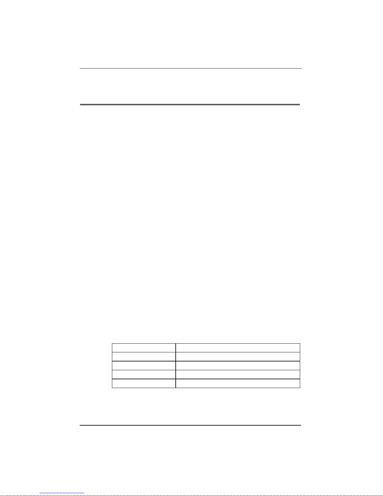
The reference for the level of utilization is based on the speed of the port that
is running. For example, a port that is running in 10M half duplex, the 100%
stands for the bandwidth of 10M. Following table show the relation for each
speed:
SPEED 100% Stands for:
10M half duplex 10M
10M full duplex 20M
100M half duplex 100M
100M full duplex 200M
Page 24

Mini Console
3-8
Observing Collision Level
When Collision is the menu item in the Message Zone, the Port Number will
be illuminated for each port that is connected and the Bar Gauge will
continuously move up or down indicating the percentage of Collision for
these ports. Collision occurs when two or more ports send data to the same
port at approximately the same time. The Collision percent can be calculated
with the following formula.
Collision Ratio = (number of packets collided / number of packets
transmitted) * 100.
Monitoring Ports Status
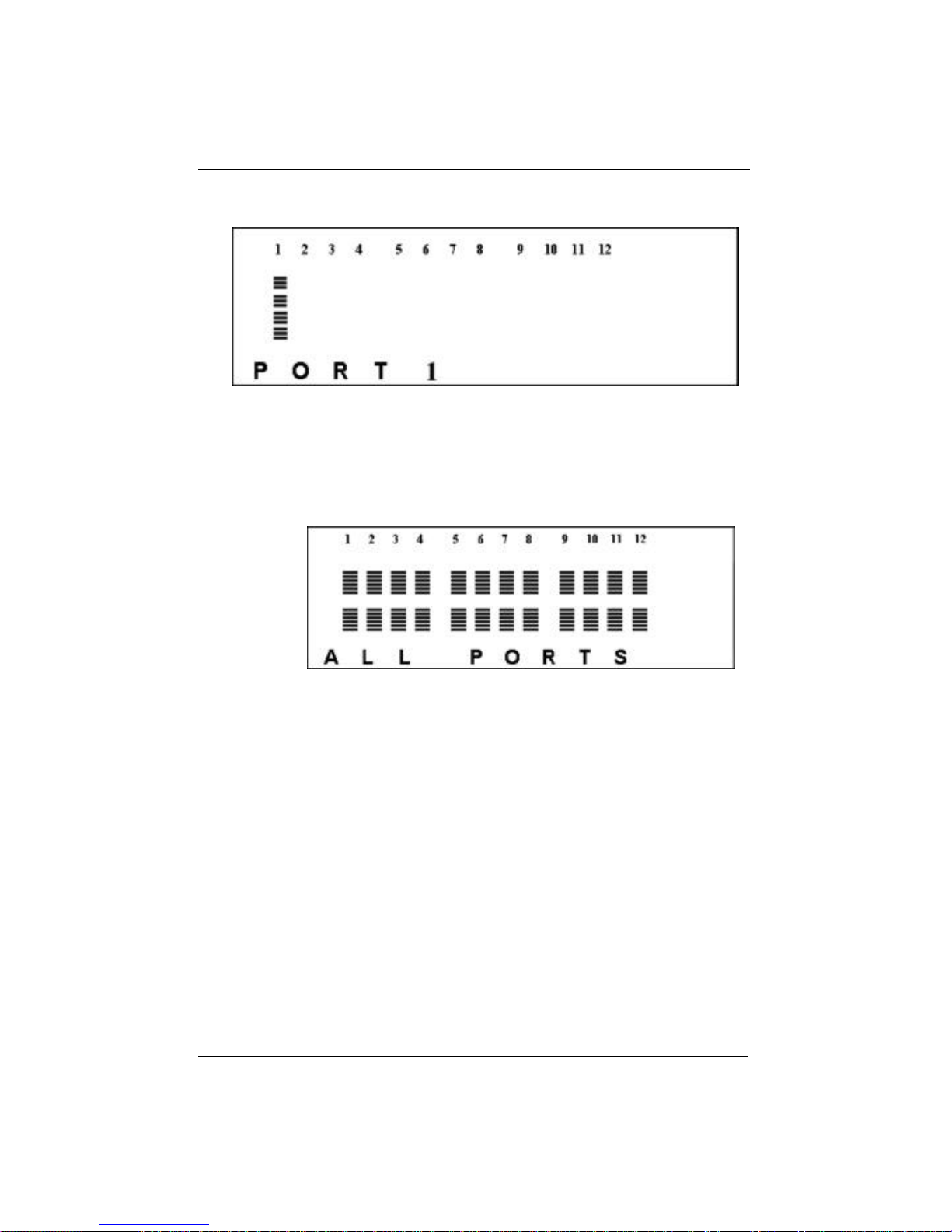
Users can view the status of all 12 ports simultaneously or individually with
the PORT STATUS menu.
Figure 3.4 Port Status
When monitoring individual ports, the status is auto cycled through each
setting, the configuration is displayed in the Message Zone and the bar scales
under the port number are illuminated.
Page 25
Mini Console
3-9
When monitoring All Ports, the status is not auto cycled, press <Next> to
view each configuration. The configuration is displayed in the Message Zone
and the bar scales under the port numbers that are configured to this setting
are illuminated. No bar scales are visible for ports that are not set to the
configuration displayed in the Message Zone.
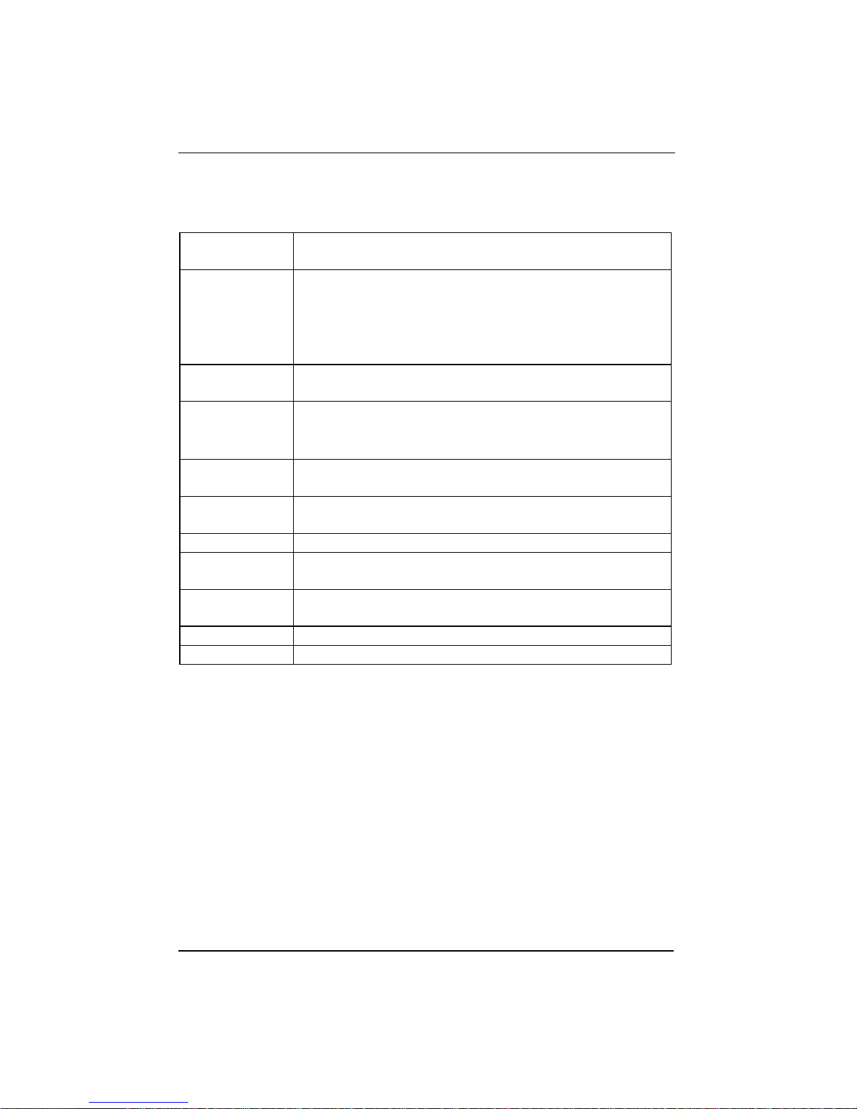
Table 3.3
Page 26

Mini Console
3-10
All 8/12 ports can be running at the same or different settings. It is useful to
check the port setting to see if it has been running in the desired mode.
PORT STATUS PORT 1~8/12 Auto scrolls through the selected
port’s current settings.
ALL PORTS 10M PORTS
100M PORTS
HALF DUPLEX
FULL DUPLEX
ENABLED
DISABLED
CUT-THROUGH
STORE-FWD
VLAN GROUP
BUFF MODE H
BUFF MODE M
BUFF MODE L
BACK
MAIN MENU
MAIN MENU
Table 3.4 Port Status
Monitoring Port Detail
Information
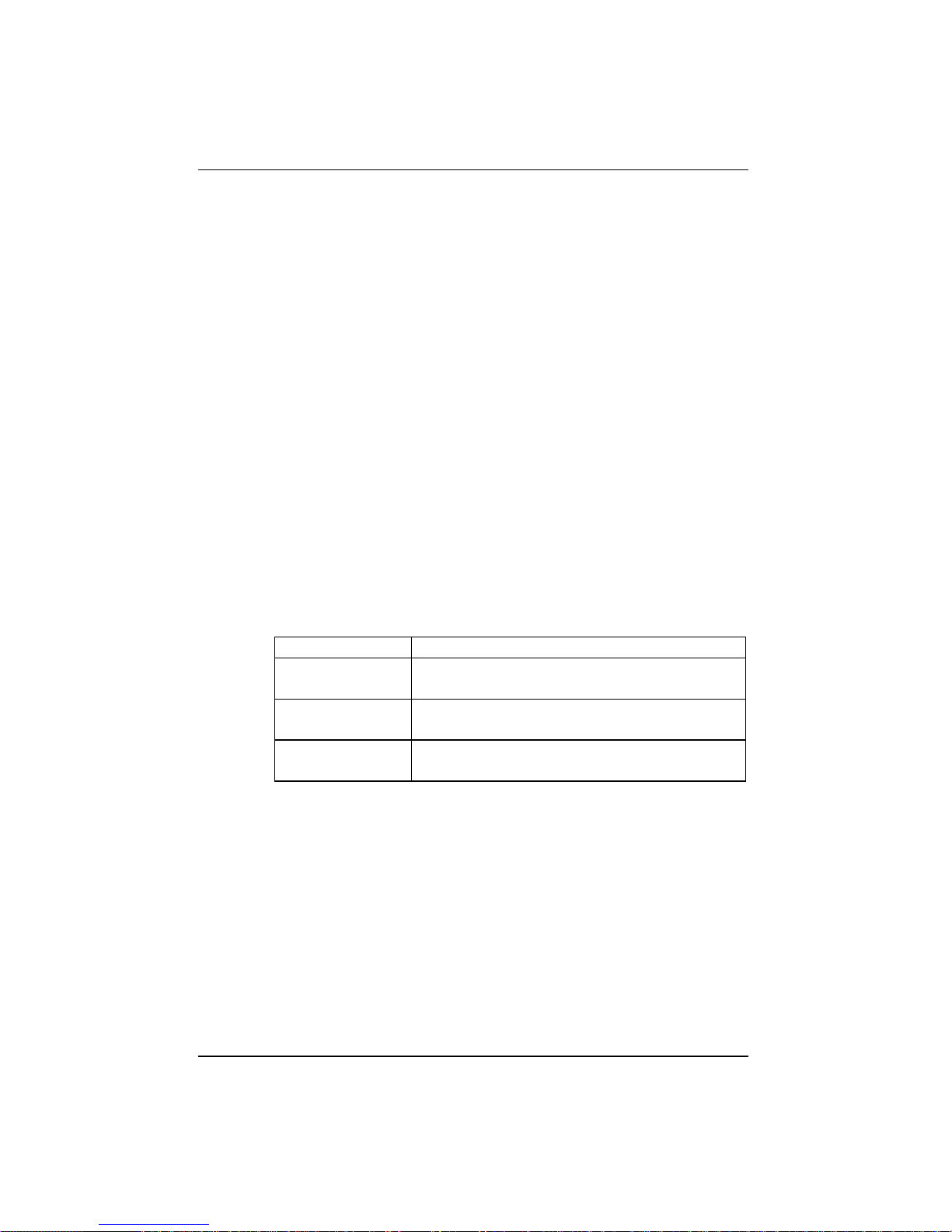
The STATISTICS menu displays the statistic counters of ports. It may be
helpful to look at the counters to isolate network problems. All the counters
display the accumulated value from the time the switch was powered on.
Page 27
Mini Console
3-11
The table below lists the counters displayed in the Statistics menu.
PORT 1~8/12 To assign a port which counters are going to be
displayed.1~8/12
Rx FRAME Displaying the total number of good packets received
including:
Unicast packets
Broadcast packets
Multicast packets
Rx OCTETS To display the count of data and padding octets in frames
that were successfully received.
Rx--PKT ERR Packets received with any of the following errors:
The packet contains a CRC error
The packet is oversize
Rx--ALIGN
ERR
To display the number of alignment errors.
OVERSIZE
Rx
To display the number of packets received that were
longer than 1532 octets and were otherwise well formed.
Tx FRAME
To display the number of packets transmitted successfully.
Tx OCTETS To display the count of data and padding octets of frames
that were successfully transmitted for the selected port.
PKT LOSS To display the number of error free packets received by
this port that were dropped due to transmit buffer full.
BACK Go back to upper level.
MAIN MENU Return to the main menu.
Table 3.5 Port Statistics Counters
Page 28
Mini Console
3-12
Optimizing Network
Performance
When the network traffic is heavy, overloaded ports can be identified by
watching the Utilization or Collision Ratio. It may be the time to tune the
system to match the environment.
Since the system resources are shared by all ports, the system allocates a
limited budget to every port to prevent one failed port from using up all the
resources. However, since the loading varies from port to port, the resources
allocated for each port should be changed based on the traffic via the MiniConsole to get the best network performance.
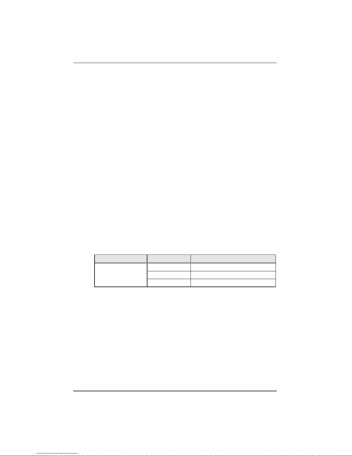
Three resource modes are available, Low, Medium and High .
The following table shows the resource distribution between modes.
MODE Using Condition
Low The port assigned the lowest amount of
resources.
Medium The port assigned a medium amount of
resources.
High The port assigned the highest amount of
resources.
Table 3.6 Resource Mode
Page 29

Mini Console
3-13
Configuring Ports
All the ports of FSW-0802/1201TX support Auto-Negotiation and the default
for all ports are configured in this mode. In the Auto-Negotiation mode, the
switch learns the setting of the opposite site and configures itself to meet its
counter part.
However, in rare conditions you should configure manually, such as when
the opposite site does not support Auto Negotiate.
To configure a port, first select the port and then select the desired setting.
PORT SETTING>PORT (1~8/12)><setting >
When a setting is selected, an asterisk symbol ( ‘*’) will be added to the first
character of the string. Making it convenient to check what the settings for
these ports are, by just going through the sub menu of PORT SETTING,
without making any confirmation. When you see an item that begins with an
‘*’, the port is set in that mode.
While AUTO-NEGO is set, the speed and duplex selection are no longer
available. The speed and duplex will be decided by the result of the
negotiation. By contrast, if either the speed or duplex is selected, the AUTONEGO function will not work. It forces the port to run in the mode just set.
All settings will be saved in the EEPROM.
Setting the port speed forces the port to use the selected speed only, if the
device being contacted is set at a different speed, the data will not be sent.
When the setting is Auto Negotiate, the port will negotiate to the fastest
speed available to both ports.
If the port being contacted doesn’t have Auto Negotiate, then this port must
be configured to match the port being contacted.
Page 30

Mini Console
3-14
PORT
SETTING PORT 1~8/12 10BASE-T
100BASE-T
AUTO-NEGO
FULL DUPLEX
HALF DUPLEX
ENABLE
DISABLE
CUT THROUGH
STORE FWD
VLAN GROUP VLAN 1~8
BACK
MAIN MENU
BUFFER MODE H
BUFFER MODE M
BUFFER MODE L
BACK
MAIN MENU
MAIN MENU
Table 3.7 Port Settings
Page 31

Mini Console
3-15
VLANs
Hub FSW-0802/1201TX supports up to 8 virtual LANs (VLANs). VLANs
effectively divide the ports into separate domains through software. Ports in
one VLAN cannot communicate with ports in another VLAN. To allow ports
from different VLANs to communicate, assign them to a common VLAN.
You can configure each port to join one VLAN or more than one of the 8
VLANs through the Port Setting menu. The default assigns all ports to all
VLANs simultaneously.
To Configure VLANs:
PORT SETTING><select port>VLAN GROUP><VLAN 1~8><press and hold Enter>
An “*” appears before the VLAN # that the port is configured in. To change
to a different VLAN, press and hold Enter at the desired VLAN, an “*”
appears before the VLAN # and the “*” is removed from the previously
configured VLAN.
Selecting a Buffer Mode
Ports on the FSW-0802/1201TX can be individually set to one of three buffer
modes, L (low), M (medium) or H (high). However it is important to note
that certain ports share the same memory resources and are grouped together.
When selecting buffer modes for ports you should consider a group of ports
and distribute resources between the ports within that group. If you set the
buffer mode the same (for example High) for all the ports in a group, it is the
same as setting them all to medium or low and there will be no gain in
performance.
Page 32

Mini Console
3-16
FSW-1201TX Buffer Groups
Table 3.8 shows the ports that are grouped together and share the same
resources for model FSW-1201TX. There are 3 groups and the resources
between groups, is independent.
1,2,7 and 8 These ports share buffer resources and constitute a
group. For a gain in performance you may want to
set one port in this group to High, 2 ports to
Medium and one port to Low.
3,4,9 and 10 These ports share buffer resources and constitute a
group. For a gain in performance you may want to
set one port in this group to High, 2 ports to
Medium and one port to Low.
5,6,11 and 12 These ports share buffer resources and constitute a
group. For a gain in performance you may want to
set one port in this group to High, 2 ports to
Medium and one port to Low.
Table 3.8 FSW-1201TX Buffer Groups
FSW-0802TX Buffer Groups
Table 3.9 shows the ports that are grouped together and share the same
resources for model FSW-0802TX. There are 2 groups and the resources
between groups, is independent.
1,2,5 and 6 These ports share buffer resources and constitute a
group. For a gain in performance you may want to
set one port in this group to High, 2 ports to
Medium and one port to Low.
3,4,7 and 8 These ports share buffer resources and constitute a
group. For a gain in performance you may want to
set one port in this group to High, 2 ports to
Medium and one port to Low.
Table 3.9 FSW-0802TX Buffer Groups
Page 33

Mini Console
3-17
Changing the system setting to Low Mode:
PORT SETTING>PORT x><BUFF MODE L>Press and Hold Enter
Changing the system setting to Medium Mode:
PORT SETTING>PORT x>< BUFF MODE M >Press and Hold Enter
Changing the system setting to High Mode:
PORT SETTING>PORT x>< BUFF MODE H>Press and Hold Enter
Unit Configuration
Broadcast Storm Protection
Some devices in the network may generate broadcast storms, thereby
jamming the network with broadcast packets. It may take about 6-7 seconds
to detect a broadcast storm.
When the Broadcast Storm Protection is Enabled, the system will monitor the
incoming packets to see if that port is enduring a broadcast storm. While
Broadcast Storm is detected, the port will be disabled temporarily and the
frame around the port number will blink. The message zone will show the
message “BRDCST STORM” altering normal display. Every 2 minutes, the
port will be released to see if it is still enduring the broadcast storm.
The Broadcast Storm Protection function is disabled when shipped from
manufacturer. This function can be enabled through the Mini Console. The
command sequence is:
UNIT CONFIG > STORM DET > ENABLE><Enter and hold>
After the command is entered, it will be saved in the EEPROM.
Page 34
Mini Console
3-18
Loop Isolation
Loop Isolation is an important feature of the FSW-0802/1201TX. This
condition could exist if two ports are inadvertently connected to each other
causing a loop.
The switching device can not sustain a loop because it produces Broadcast
Storm thereby jamming the system with looping packets. FSW-0802/1201TX
supports isolating the looped ports. If the function is enabled, the device will
monitor all ports to see if there are any loops.
Once a loop is detected (which takes about one second), it will disable that
port. The port number frame will blink indicating it has been temporarily
isolated. Every 8 minutes, the port will be released to see if it is still looping.
The function of LOOP ISOLATE is disabled at the time it shipped from
manufacturer. You have to enable the function through Mini-Console. The
command sequence is:
UNIT CONFIG > LOOP ISOLATE > ENABLE><Enter and hold>
After the command is entered, it will be saved in the EEPROM.
Sub-Menu Command To Set Press:
Loop Isolation Enable Enter and hold
Disable Enter and hold
Back Enter
Table 3.10 Loop Isolation
Lock the Console
Setting this option to Enable locks the system settings. If there is no
password set, a prompt will request one be entered.
UNIT CONFIG > CONSOLE LOCK> ENABLE><Enter and hold>
Page 35

Mini Console
3-19
If a User’s Password has been set and enabled, the unit does not allow
changing system settings, such as port settings and unit configuration, unless
the correct password is keyed in thereby unlocking the Mini-Console.
Unlock the Console
Once the console is locked, a password will be asked when the menu item
UNIT CONFIG is selected.
In the password session, a message “* * * *_ _ _ _ PSW ” will be shown. You
have to key in the correct password to enter the submenu. The regular
Password assigned by you and the Back door Password are accepted. The
first four asterisks are used for normal password while the others are used for
Back door Password. The regular password is assigned by the user and the
Back door Password depends on the Key Code. See “Back Door Password”
on page 3-20 for more information.
After the password session is passed, you can go to the sub menu of UNIT
CONFIG. The lock sign on the Mini-Console is OFF and you are free to
configure any settings.
Secure the Switch
Two passwords are provided to protect the device from being accessed
anyone other than administrator. Further information regarding Password and
Back door Password, please refer to “Unlock the Console ” section.
Set Password
You can configure a password by enter a 4 digit password using the numbers
from 0~9. The default is “0000”.
To set the password:
<UNIT CONFIG><SET PASSWORD>enter 4 digits.
Page 36

Mini Console
3-20
After SET PASSWORD is selected, four “*’s” are displayed and the first “*”
is blinking indicating it is the current digit. Enter a new number using the
<Prev> key. Use the<Next> key to move from one digit of the password to
the next one. When the 4 password digits have been entered, press <Enter> to
complete the password setting. Ensure that you do not loose your password.
Cancel Password
Enter the command UNIT CONFIG > SET PASSWORD. Entering four
blanks will clear the password when the console is unlocked.
In Case You Forget the Password
In case the password is forgotten the back door password can be used.
Back Door Password
The Back Door Password is useful in case you are locked out of the system
because you’ve lost the password. The back door password is always enabled
and is derived from “Key Code XX” under the main menu item “System
Info ”. The “XX” is a random number selected by the device every time the
system is powered on and the number is incremented by 1 every 2.5 days.
Please call technical support from your supplier to find out your current
“XX” mapping to an 8-digit password!
Restart the Switch
In case you want to reset the FSW-0802/1201TX, simply enter the command:
UNIT CONFIG > SYS RESTART ><Enter and hold>
Page 37

Mini Console
3-21
The command will reset the switch. The data in EEPROM memory will not
be lost, only new configuration settings will be updated.
Restart the Switch in the event that it does not behave normally.
Restore System Setting
In case you want to set the system setting to the default value, simply enter
the command:
UNIT CONFIG > SYS DEFAULT > <Enter and hold>
The command will reset the switch and the data in EEPROM will be set to
the default values.
Page 38

Mini Console
3-22
About The Switch
System Info
The Mini-Console will auto cycle through systems settings. Press any key to
disable. When you enter the following command:
SYSTEM INFO ><Press Enter>
The following is displayed:
SSRAM 12M (packet buffer)
HW VER 2-1
SW VER 1.0
KEY CODE DB
Fan Failure
If there is a fan failure the message “FAN LOOP BCS” appears in the System
Info menu.
Page 39

Technical Specifications
* Warning: The MII is not hot-pluggable.
A-1
Appendix A
Technical
Specifications
Standards Compliance
IEEE 802.3 10BASE-T & 10BASE5
Ethernet
IEEE 802.3u 100BASE-TX Fast Ethernet
Number of Ports
FSW-0802TX
8 10/100BASE-TX Nway Ethernet (RJ-45)
ports
1 MII * port shared with port 5
FSW-1201TX
12-10/100BASE-TX Nway Ethernet
(RJ-45) ports
1 MII * port shared with port 7
Smart Console Operation
Capable of device configuration,
device/port management, and network
monitor
Console management through menu
operation
Displaying traffic utilization and collision
status per port
Monitoring each port’s status and
statistics by users’ intention
Setting up selected ports
Three console keys for above
management features
Graphic and alpha numeric VFD display
panel
Smart Port Setting
Page 40

Technical Specifications
A-2
Port enable/disable
Speed selection: 10 Mbps, 100 Mbps, or
auto-negotiation
Full/half duplex
Fragment free/ Fast Store-and-forward
switching mode selection
VLAN setting
Smart Network Monitoring
Overall port status display
Monitoring utilization, collision.
Smart Switching Functions
Broadcast Storm Protection
Loop detection
Flow control to prevent packet loss
Self-diagnostic and watch-dog protection
Switching Performance
RAM: 1MB per device FSW-0802TX
1.5MB per device-FSW-1201TX
Port memory: buffer memory: 3 Userdefined. modes
Packet filtering/forwarding rate: 148,800
pps per 100BASE-TX port; 14,880 pps
per 10BASE-T port
MAC address learning cap. : 8k per
device
Power Requirements
100 - 240 VAC, 50/60 Hz
Internal universal power supply
Environment
Operating Temperature: 0°C to 50° C
Storage Temperature: -30° C to 60° C
Operating Humidity: 5% to 95% noncondensing
Safety Regulations
CUL (UL & CSA), LVD
EMI Certifications
CE Mark, FCC Class A, VCCI Class 1
Dimensions
W x D x H: 298 x 192 x 55 mm (1.25 U
height)
Weight
1.5 kg
Stacking
Using EIA 19” Racks
Page 41

Error Messages
B-1
Appendix B
Error Messages
In several cases when the system detects abnormal conditions, it will generate
an error message and the system may halt. The following table shows how
many error messages may occur and what the system will do.
Page 42

Error Messages
B-2
ERROR
MESSAGE
CAUSE SYSTEM
REACTION
EEPROM
ERROR
The EEPROM did not pass the
read/write test.
Halt
FAN
FAILED
The device detected that the fan is not
working.
Halt, to protect
the device
EPM NO
MEM
EEPROM is out of memory System restart
EPM WR
ERROR
Error when the device is writing
EEPROM memory
No action until
next power up
EPM RD
ERROR
Error when the device is reading the
EEPROM memory
No action is
taken until next
power up
CHECKSUM
ERR
The checksum in the EEPROM is
corrupted
System restart
and the data will
be brought to
default value
PCI BUS
ERR
Halt
VENDOR ID
ERR
Chip vendor ID read error Halt
Page 43
Appendix C
C-1
Chapter 4
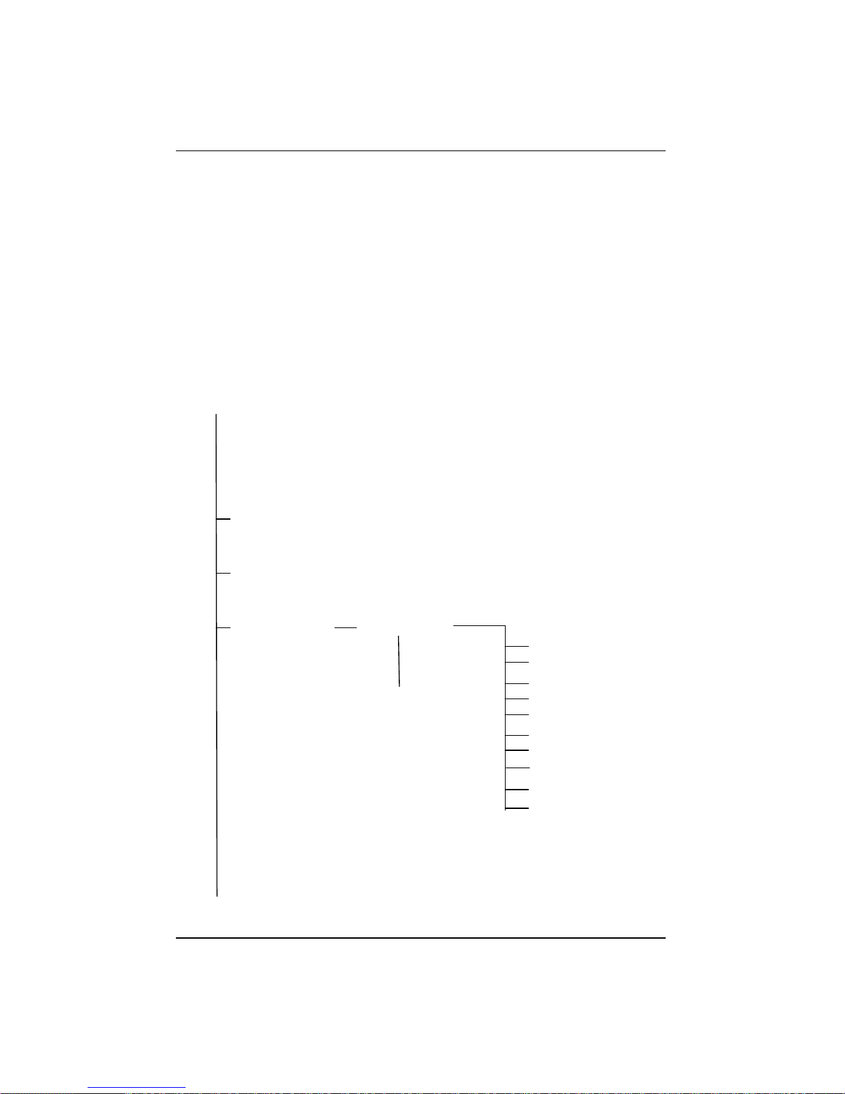
Menu Tree
Root
UTILIZATION
COLLISION
STATISTICS PORT 1~12
MAIN MENU
RX FRAMES
RX OCTETS
Rx-ALIGN ERR
Rx-PKT ERR
OVERSIZE Rx
Tx FRAMES
Tx OCTETS
PKT LOSS
BACK
MAIN MENU
Page 44

Appendix CC-2
PORT
STATUS PORT 1~12 Auto scrolls
through the port ’s
settings
ALL PORTS
10M PORTS
100M PORTS
HALF DUPLEX
FULL DUPLEX
ENABLED
DISABLED
CUT-THROUGH
STORE-FWD
VLAN GROUP
BUFF MODE H
BUFF MODE M
BUFF MODE L
BACK
MAIN MENU
MAIN MENU
Page 45
Appendix C
C-3
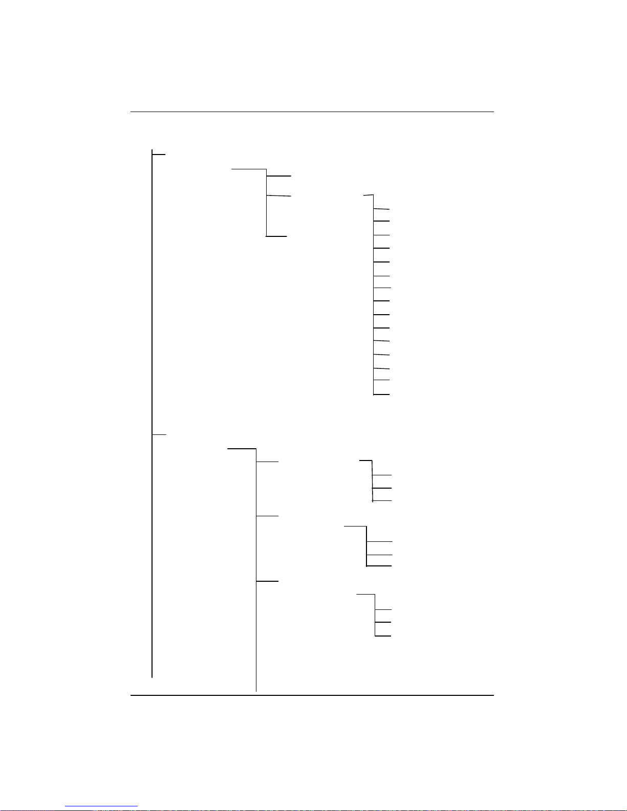
****_ _ _ _PSW
Enter a four digit
password
PORT
SETTING
PORT 1~12
MAIN MENU
10BASE-T
100BASE--X
*AUTO-NEGO
HALF DUPLEX
FULL DUPLEX
*ENABLE
DISABLE
CUT THROUGH
*STORE FWD
VLAN GROUP
BUFF MODE H
*BUFF MODE M
BUFF MODE L
BACK
MAIN MENU
UNIT
CONFIG
STORM DET
ENABLE
*DISABLE
BACK
LOOP
ISOLATE
ENABLE
*DISABLE
BACK
FLOW
CONTROL
ENABLE
*DISABLE
BACK
Page 46
Appendix CC-4
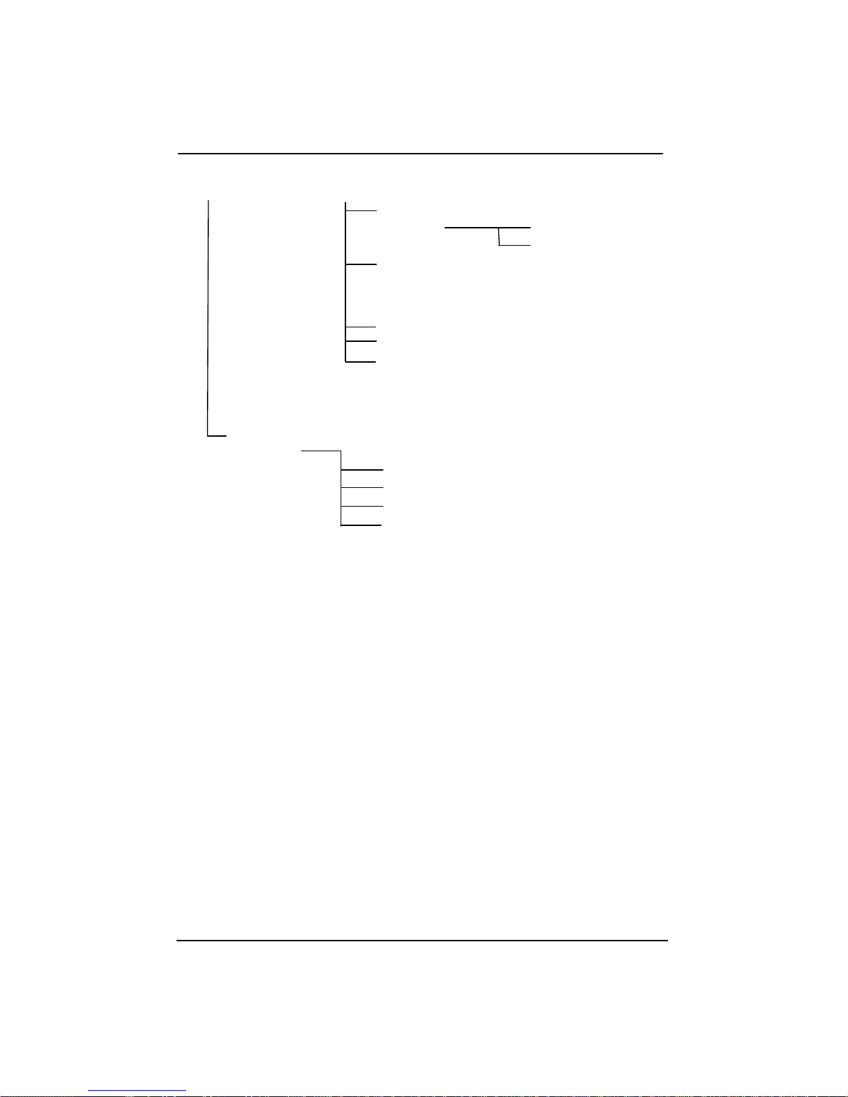
CONSOLE
LOCK ENABLE
BACK
SET
PASSWORD
**** PSW
SYS RESTART
SYS DEFAULT
MAIN MENU
SYSTEM
INFO
SSRAM 12M
HW VER 2-1
SW VER 1_00
KEY CODE DB
Page 47

53100000300A
 Loading...