

Page 1
CMS :
Central Management System
User Manual
Ver. 1.6.0.110630.001
Page 2

Table of Contents
Part 1: CMS Overview ..................................................................................................................................................... 4
System Introduction ....................................................................................................................................................... 5
Client/Server Architecture .................................................................................................................................................................5
System Requirements .................................................................................................................................................... 6
System Setup ......................................................................................................................................................................................6
Multiple Monitor Configuration ........................................................................................................................................................7
Installation ....................................................................................................................................................................... 8
SQL Server 2005 Express ..................................................................................................................................................................8
CMS Server ..................................................................................................................................................................................... 12
CMS Client ...................................................................................................................................................................................... 14
CMS Matrix ..................................................................................................................................................................................... 15
Uninstalling CMS System ................................................................................................................................................................ 15
Getting Started with the CMS System ......................................................................................................................... 17
Main Console Configuration ........................................................................................................................................................... 17
SQL Server ...................................................................................................................................................................................... 17
CMS Alarm Server .......................................................................................................................................................................... 18
CMS Client ...................................................................................................................................................................................... 19
CMS Matrix ..................................................................................................................................................................................... 20
CMS System Overview ................................................................................................................................................. 22
CMS Server Window Introduction................................................................................................................................................... 22
CMS Client Window Introduction ................................................................................................................................................... 23
CMS Client Setting .......................................................................................................................................................................... 26
Customizing Client Appearance ...................................................................................................................................................... 26
System Operate Mode/Edit Mode .................................................................................................................................................... 28
CMS Matrix Window Introduction .................................................................................................................................................. 28
SQL Server Introduction ................................................................................................................................................................. 28
Part 2: Administrator Functions (Se tti ng Up the CMS S ystem) ................................................................................ 29
Servers/Devices ............................................................................................................................................................ 30
Adding/Editing/Remov ing Se r v e r G r oups ......................................................................................................................................... 30
Adding/Editing/Removing Servers................................................................................................................................................... 30
Maps ............................................................................................................................................................................... 32
Map Hierarchy ................................................................................................................................................................................ 32
Adding/Editing/Removing Maps ...................................................................................................................................................... 32
Servers/Devices on Map ............................................................................................................................................... 33
Importing Indicator Images............................................................................................................................................................. 33
Adding/Removing Device Indicators ............................................................................................................................................... 33
Edit Device Indicators ..................................................................................................................................................................... 34
Coverage ........................................................................................................................................................................ 36
Adding/Editing/Removing Coverage ............................................................................................................................................... 36
User Groups and Users ................................................................................................................................................ 37
Adding/Editing/Removing User Groups .......................................................................................................................................... 37
Adding/Editing/Removing Users ..................................................................................................................................................... 38
Alarms ............................................................................................................................................................................ 42
Adding/Copying/Editing/Removing Alarms ......................................................................................................................................... 42
Central Server Configuration Window ............................................................................................................................................ 44
Page 3

Matrix System ................................................................................................................................................................ 47
Adding/Editing/Removing Matrixes ................................................................................................................................................ 47
View Group Management ............................................................................................................................................. 49
Network Management ................................................................................................................................................... 54
CMS Server Management ................................................................................................................................................................ 54
Matrix Management ........................................................................................................................................................................ 54
Importing/Exporting CMS Client Configuration.......................................................................................................... 57
Loading/Saving CMS Server Configuration ................................................................................................................ 58
License Management Tool ........................................................................................................................................... 59
License Management Tool Overview .............................................................................................................................................. 59
Activate/Transfer L icense ................................................................................................................................................................ 60
Part 3: User Functions (Day to Day Use) .................................................................................................................... 63
Operate Toolbar ............................................................................................................................................................ 64
Alarm Overview Window .............................................................................................................................................. 65
Recent Tab ...................................................................................................................................................................................... 65
Real-Time Ta b ................................................................................................................................................................................. 66
Output Tab and Output 2 Tab ......................................................................................................................................................... 67
Message Log Tab ............................................................................................................................................................................ 67
Alarm Log Settings .......................................................................................................................................................................... 68
Alarm Management Window and Batch Alarm Management ......................................................................................................... 68
Exporting Alarm Data to an Excel File ........................................................................................................................................... 74
Clearing Alarms .............................................................................................................................................................................. 74
Map Window .................................................................................................................................................................. 75
Adjusting Map Ap pe ar a nc e ............................................................................................................................................................. 75
Navigating Between Map and Servers/ Devices .............................................................................................................................. 75
Searching for devices on the server list or on map.......................................................................................................................... 76
Map Indicators ................................................................................................................................................................................ 77
Map Display Settings ...................................................................................................................................................................... 78
Device Alarm Menus ..................................................................................................................................................... 79
Common Functio ns ......................................................................................................................................................................... 80
Camera Alarm Menu ....................................................................................................................................................................... 81
Metadata Alarm Menu .................................................................................................................................................................... 84
Output Device Alarm Men u ............................................................................................................................................................. 87
Server Alarm Menu ......................................................................................................................................................................... 87
Advance Alarm Search .................................................................................................................................................................... 88
Matrix View .................................................................................................................................................................... 90
Matrix View Toolbar ....................................................................................................................................................................... 90
Showing Video on a Matr ix ............................................................................................................................................................. 90
Joystick Control .............................................................................................................................................................................. 92
Log Viewer ..................................................................................................................................................................... 94
Remote Playback Shortcut ........................................................................................................................................... 95
Server Summary............................................................................................................................................................ 96
CMS Client Software version ....................................................................................................................................... 97
Cross Time Zone Scenario ........................................................................................................................................... 98
Page 4

Part 1: CMS Overview
This section describes the CMS architecture and how to install and start the CMS system. It includes the following sections:
System Introduction, Sys tem R equire men ts, Installation, Getting Started with the CMS System, and CMS Client Overview
.
4
Page 5
System Introduction
The Central Management System (CMS) is a powerful system which brings traditional central management systems o ut of th e
control room through Internet access. The netw ork -based key operation system can manage unlimited combinations of analog
and network cameras worldwide, via unlimited w or king station s in diff erent lo cations. CMS is the universal solution for large
scale projects.
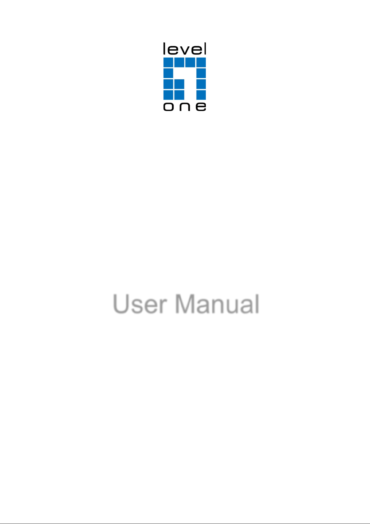
Client/Server Architecture
The CMS System uses client/server architecture to manage unlimited recording systems. These send events to the CMS
Alarm Server. After filtering the events, the CMS Alarm server sends alarm logs of pre-determined event s to a SQL Server
(SQL database) and CMS Client systems. The CMS Client system allows users in different locations to log in to the CMS
Alarm server and, if they have the authority, to change the system configuration. The CMS Matrix system can be viewed
as an extension of the CMS client used to populate the alarm s to additio nal mon itor s. CMS Matrix system is controlled by
CMS Client users.
Definition of Terms:
Terms Descriptions
CMS System
Recording
Server
SQL Server
CMS Alarm
Server
CMS Client
CMS Matrix
All components of Central Management system.
Front end servers of the Central Management system, consisting of Video Recording systems
which send events to CMS Alarm Server.
Database of Central Manage ment sy ste m, which backs up alarm logs.
Alarm Server of Central Management system, which filters events in order to send out alarms,
and saves configuration of CMS system. Abbreviate CMS Server or Alarm Server.
Client end software of Central Management system, which is used to log in to the Alarm Server.
Video Matrix to view live video, controlled by CMS Client.
5
Page 6
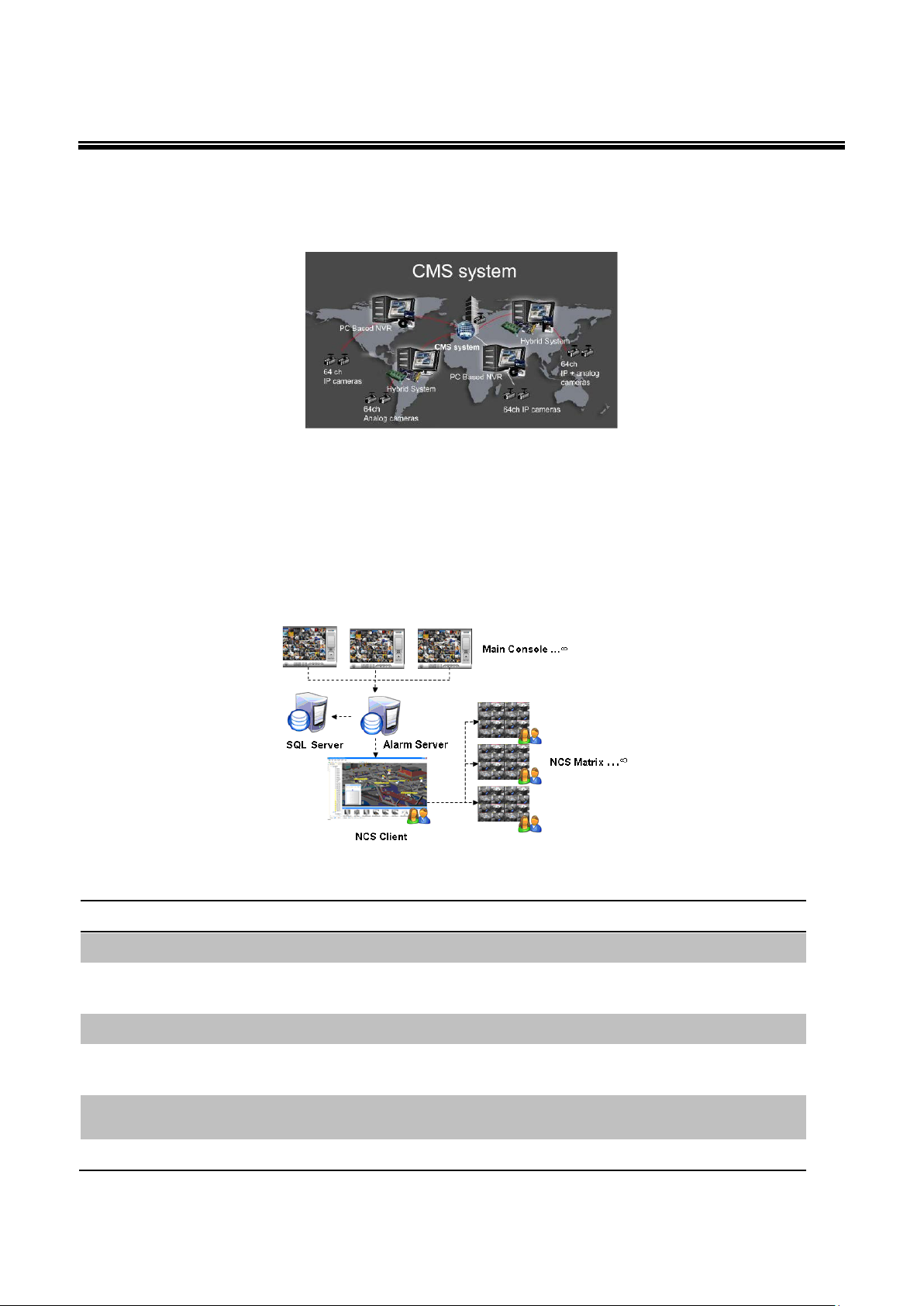
PC1
CPU
Intel Core 2 Quad Q9550 @ 2830MHz
RAM
2 GB
Hard Disk
250 GB or above
Intel 945 or 965 chip (for single monitor)
Intel P35/975 chip or nVidia nForce 650i chip (for multiple monitors)
Display
ATi X4350 or above, nVIDIA GeForce 9500series or above
Ethernet
100 baseT or above, Gigabit LAN recommended
OS
MS Windows XP Pro SP3 / Vista / 2003 / Win 7 / 2008 R2
Intel Core 2 Quad Q6660 @
2400MHz
Intel Core 2 Duo
E4500
Intel Core 2 Quad Q6660
@ 2400MHz
Intel 945 or 965 chip (for single monitor)
Intel P35/975 chip or nVidia nForce 650i chip (for multiple monitors)
System Requirem ents
System Setup
There are three scenarios for CMS system setup. Depending on customers’ budget and the size of the project, customers
can choose a suitable scenario. The system requirements for each scenario are detailed below.
Scenario A: Using one PC for all installed elements
Recommended hardware specification for Scenario A
Mother-board
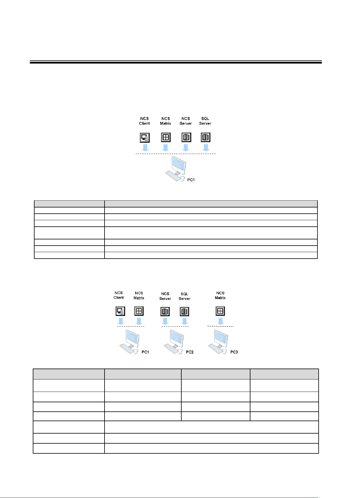
Scenario B: Using three PCs with CMS Client and CMS Matrix on PC1, CMS Server and SQL Server on PC2, and CMS Matrix on PC3
CPU
RAM 2 GB 2 GB 2 GB
Hard Disk 250 GB or above 250 GB or above 250 GB or above
Display ATi X4350 or above ATi X1600 or above ATi X4350 or above
Mother-board
Ethernet 100 baseT or above, Gigabit LAN recommended
OS MS Windows XP Pro SP3 / Vista / 2003 / Win 7 / 2008 R2
Recommended hardware specification for Scenario B
PC1 PC2 PC3
6
Page 7
Intel Core 2 Quad
Q6660 @ 2400MHz
Intel Core 2 Duo
E4500
Intel Core 2 Duo
E4500
Intel Core 2 Quad
Q6660 @ 2400MHz
Intel 945 or 965 chip (for single monitor)
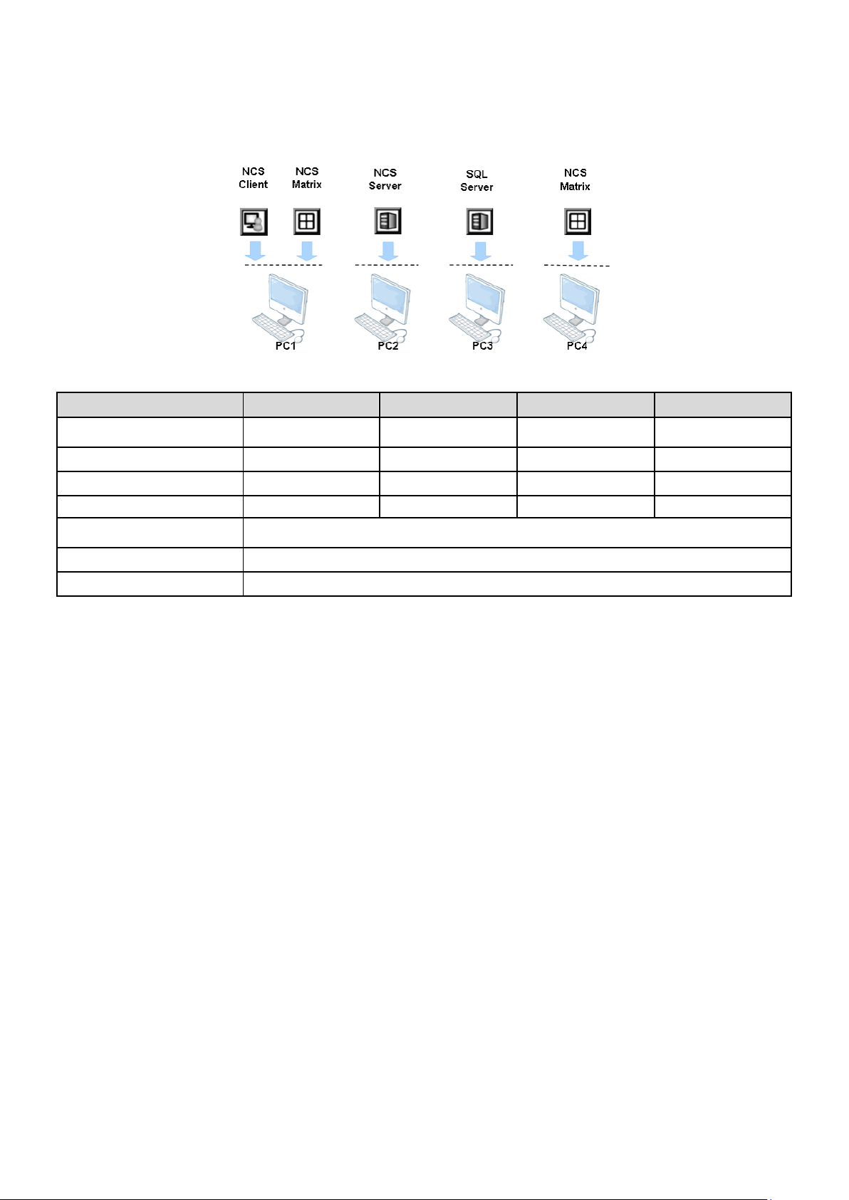
Scenario C: Using four PCs with CMS Client and CMS Matrix on PC1, CMS Server on PC2, SQL Server on PC3, and CMS Matrix on PC4
Recommended hardware specification for Scenario C
PC1 PC2 PC3 PC4
CPU
RAM 2 GB 1 GB 1 GB 2 GB
Hard Disk 250 GB or above 250 GB or above 250 GB or above 250 GB or above
Display ATi X4350 or above ATi X1600 or above ATi X1600 or above ATi X4350 or above
Mother-board
Ethernet 100 baseT or above, Gigabit LAN recommended
OS MS Windows XP Pro SP3 / Vista / 2003 / Win 7 / 2008 R2
Intel P35/975 chip or nVidia nForce 650i chip (for multiple monitors)
Multiple Monitor Configuration
For a PC running the CMS Client and CMS Matrix, it is suggested that three monitors are used: one to display the Map
window and the System Configuration window, one to display the Alarm Overview window, and one to display the live
video feed matrix. This enables efficient use of the system and saves hardware costs.
PCs using multiple monitors in this way should have a Intel P35/i975x motherboard which can support two display cards.
Each display card should be the same model, to avoid hardware conflicts.
7
Page 8
Installation
The CMS Installation CD contains the software you need to run the complete CMS system. If you are installing the system
on multiple PCs as described earlier, install the appropriate s oftware for each PC:
For the PC running SQL Server, install SQL Server 2005 Express.
For the central server PC, install CMS Server
For client PCs, install CMS Client
For PCs displaying video matrixes, install CMS Matrix.
The following sections describe installation of each element of the CMS system.
SQL Server 2005 Express
To install SQL Server 2005 Express:
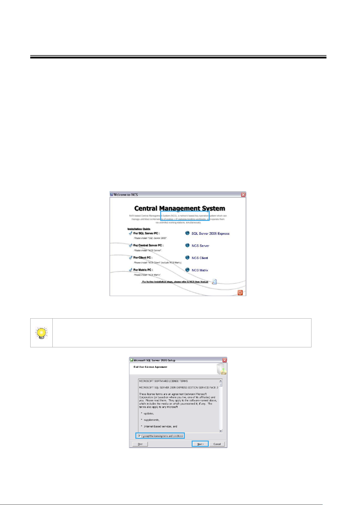
1. Insert the CMS installation CD.
2. In the Welcome to CMS window, click SQL Server 2005 Express.
If you do not have Microsoft .Net Framework 2.0 and Windows Ins taller 3.1 installed, a message will
appear. Download and install the application from the link in the message or from the toolbox directory of
installed CD.
8
Page 9
3. In the End User License Agreement dialog box, read the terms, check I accept the licensing terms and
conditions, and then click Next.
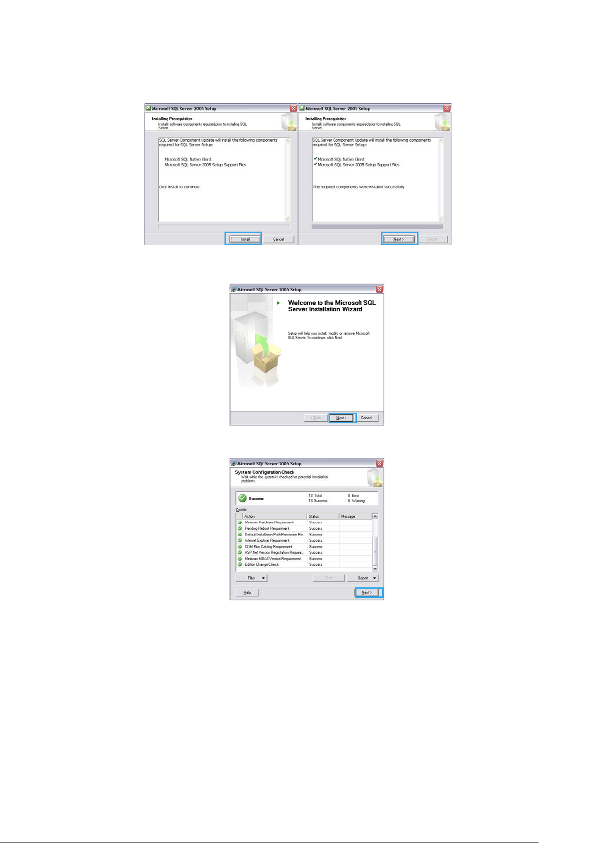
4. In the Installing Prerequisites dialog box, click Install to continue update, and then click Next to continue
installation.
5. In the Welcome to the Microsoft SQL Server Installation Wizard dialog box, click Next to install.
6. In the Syst em Configuration C heck dialog box, click Next.
9
Page 10
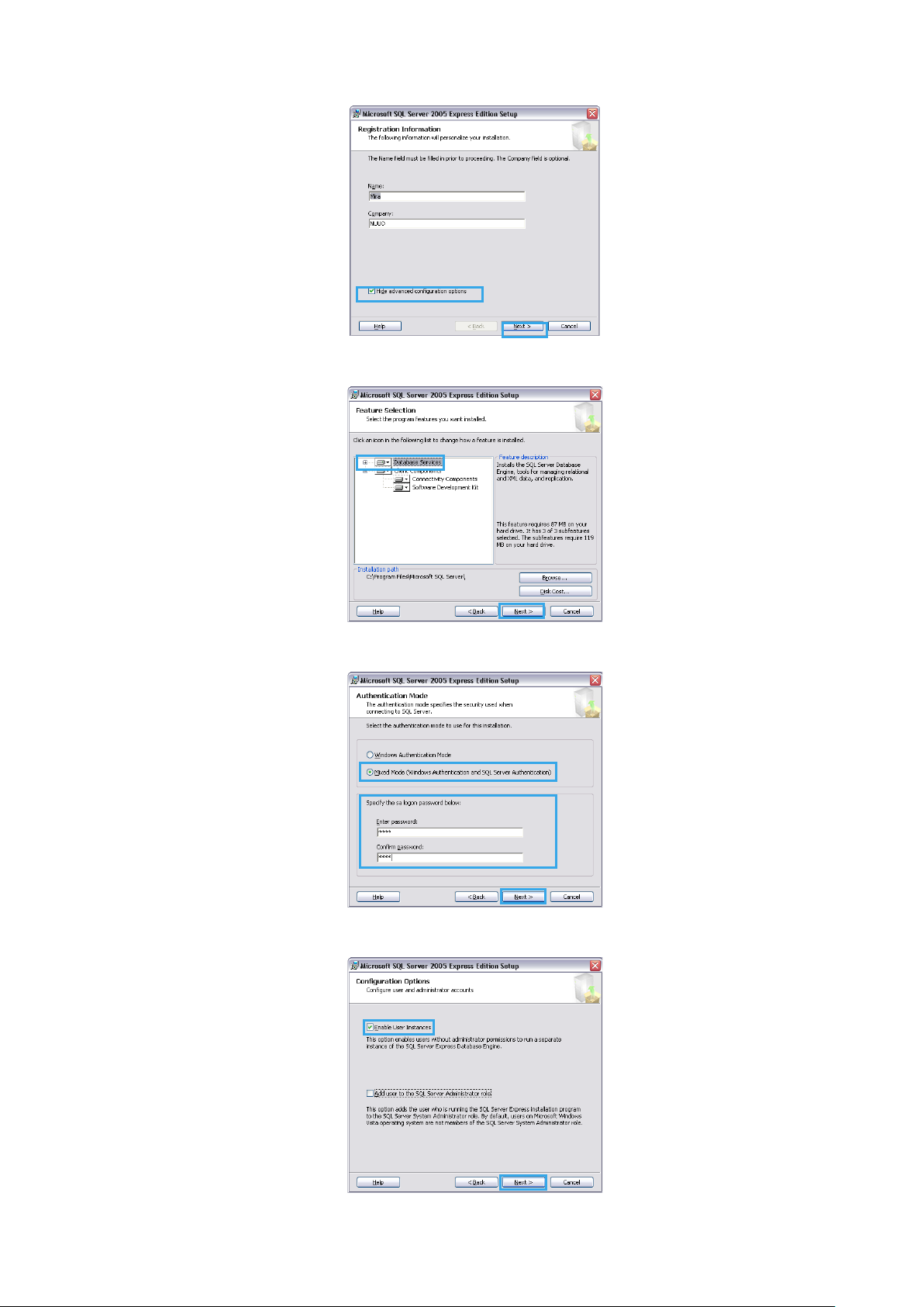
7. In the Registration Information dialog box, enter your name and company, and then click Next.
8. In the Feature Selection dialog box, select Database Services, and then click Next.
9. In the Authentication Mode dialog box, enable Mixed Mode option, and then enter and confirm a password.
10
Page 11
10. In the Configuration Options dialog box, select Enable User Instances option, and then click Next.
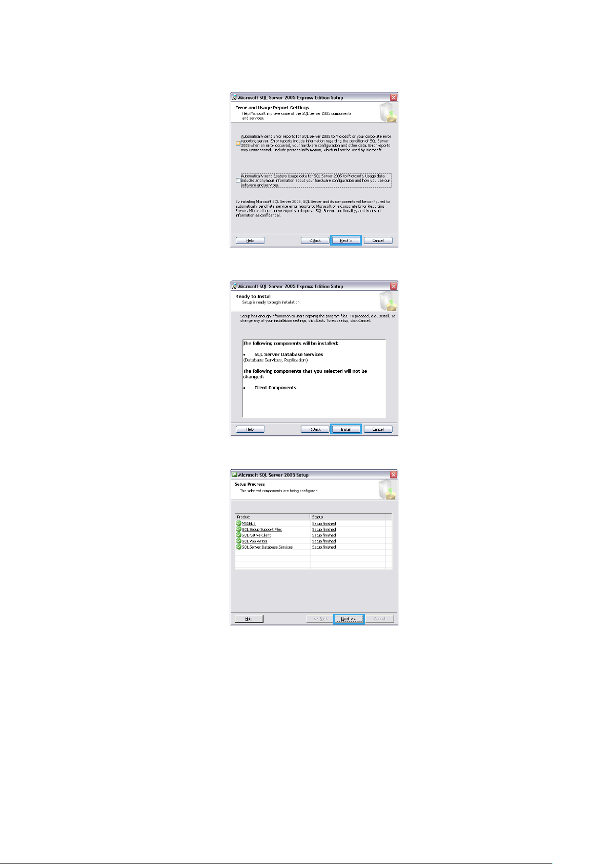
11. In the Error and Usage Report Settings dialog box, you do not need to select any option. Click Next.
12. In the Ready to install dialog box, click Install.
13. In the Setup Progress dialog box , wait for installation finish, and then click Next.
11
Page 12
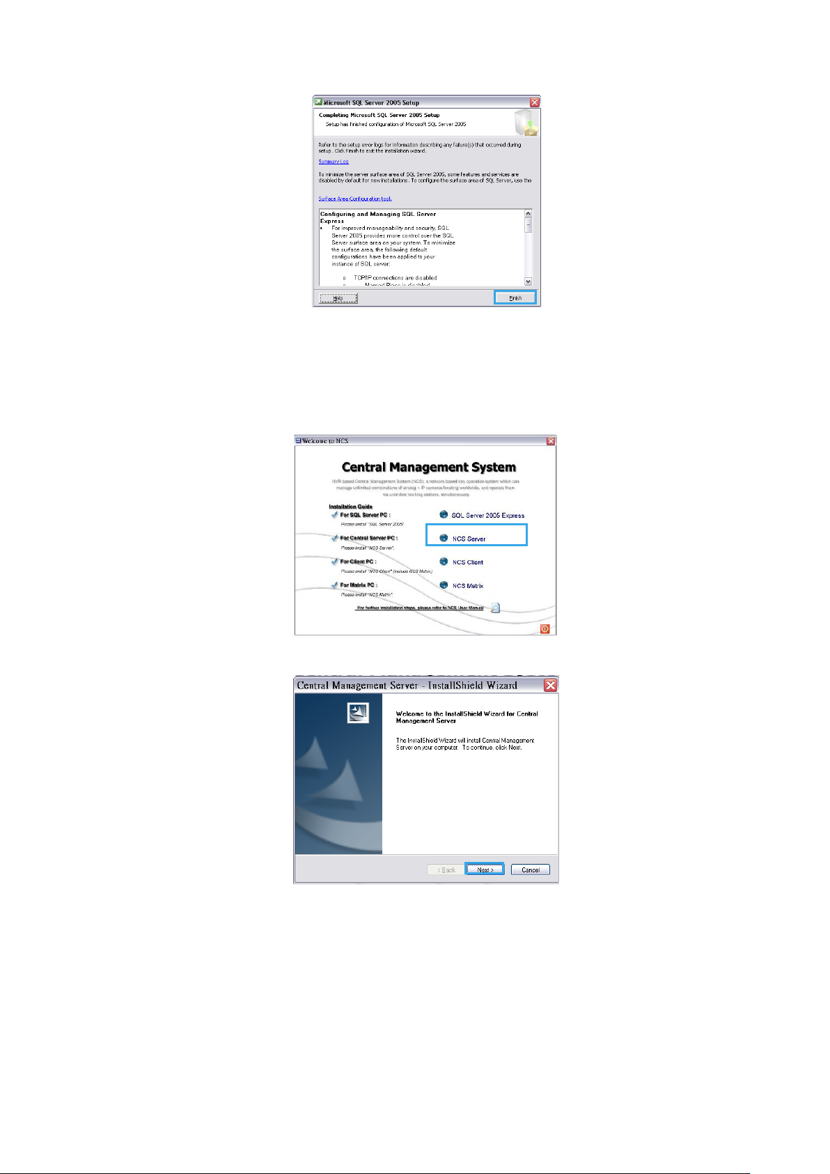
14. In the Completing Microsoft SQL Server 2005 Setup dialog box, click Finish
CMS Server
To install CMS Alarm Server:
1. Insert the CMS installation CD.
2. In the Welcome to CMS window, click CMS Server.
3. In the InstallShield Wizard di alog box, click Next to continue.
12
Page 13
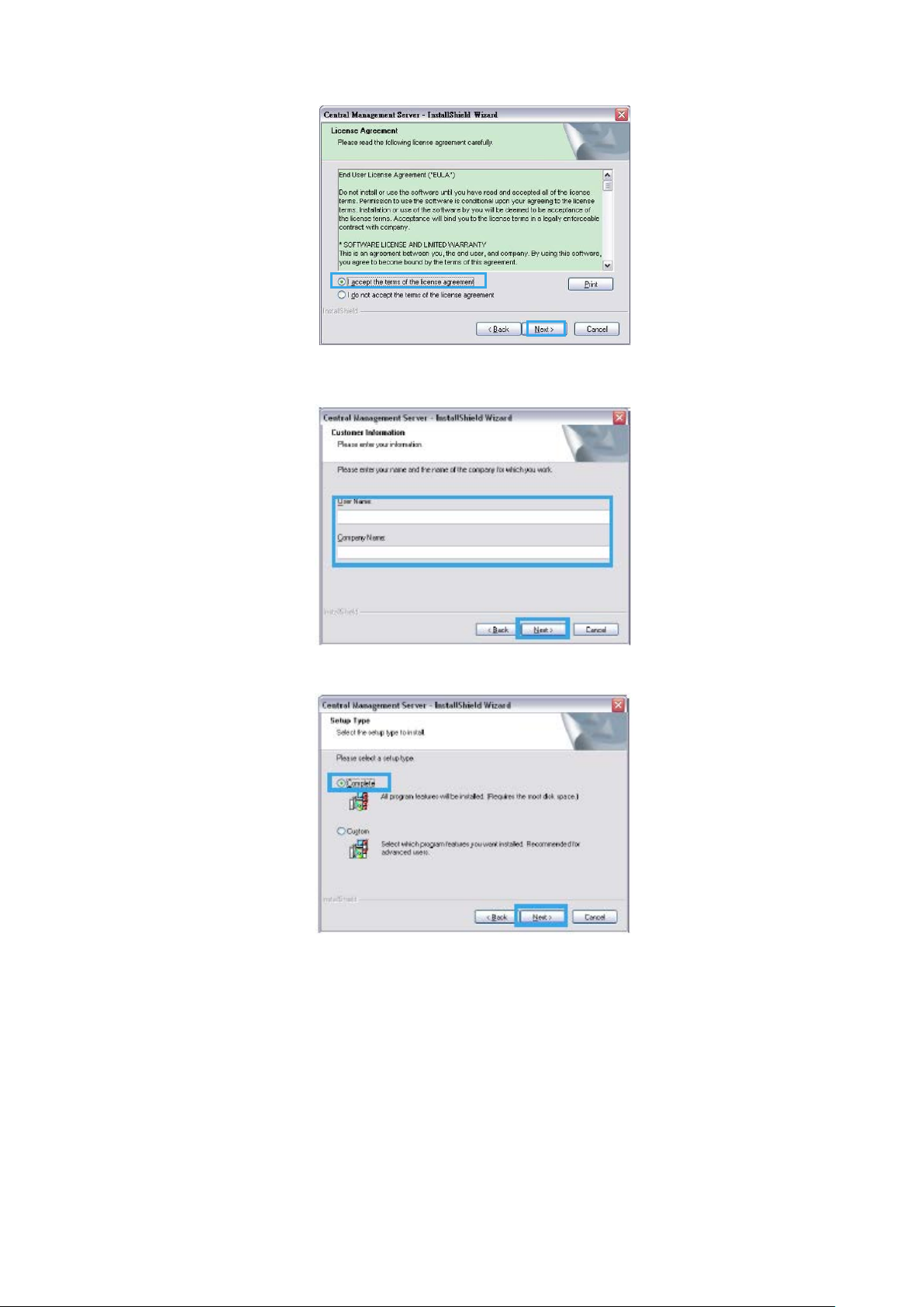
4. In the License Agreement window, read the terms, select I accept the terms of the license agreement, and
then click Next.
5. In the Customer Information window, enter your name and company, and then click Next.
6. In the Setup Type window, select Complete, and then click Next.
13
Page 14
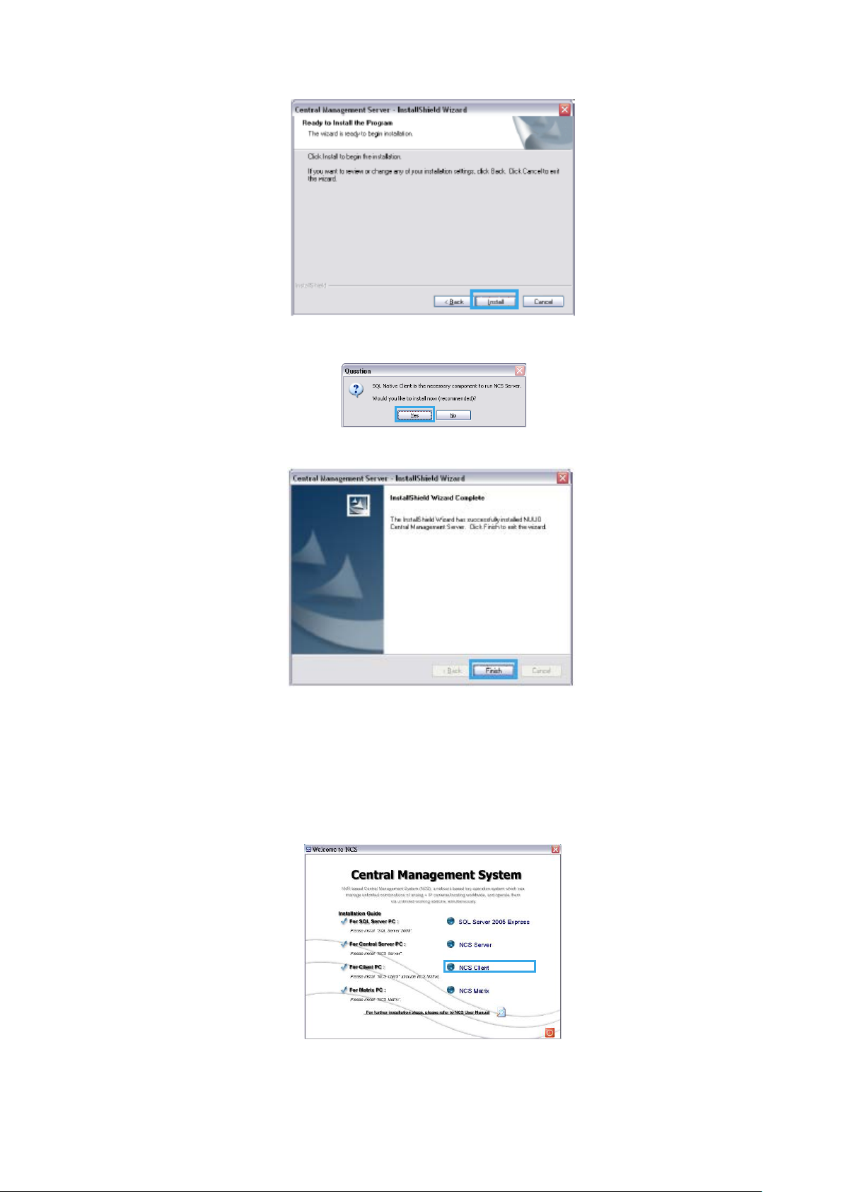
7. In the InstallShield Wizard window, click Next.
8. Please click Yes to install SQL Native Client program.
9. In the InstallShield Wizard Complete dialog box, click Finish.
CMS Client
To install CMS Client (include Matrix):
1. Insert the CMS installation CD.
2. In the Welcome to CMS window, click CMS Client.
14
Page 15
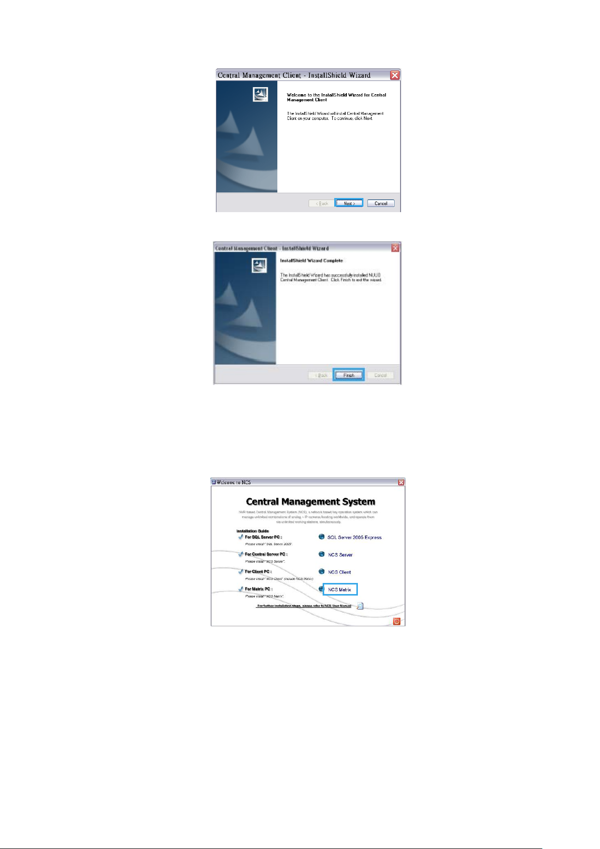
3. Complete installation as described in steps 3-7 of the To install CMS Alarm Server section on page 12.
4. In the InstallShield Wizard Complete dialog box, click Finish.
CMS Matrix
To install CMS Matrix:
1. Insert the CMS installation CD.
2. In the Welcome to CMS window, click CMS Matrix.
3. Complete installation as described in steps 3-4 of the To install CMS Client section on page 14.
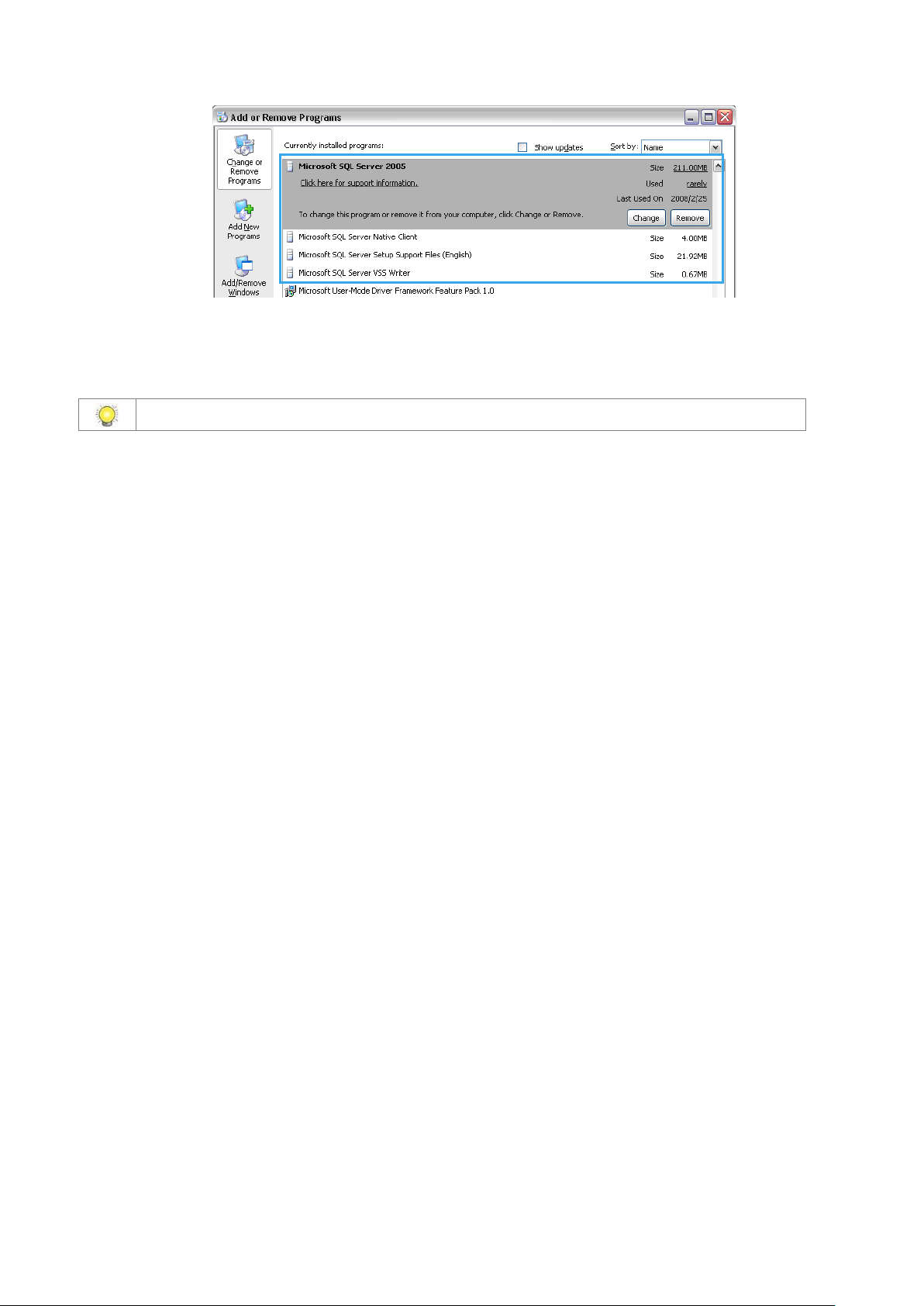
Uninstalling CMS System
To uninstall SQL Server:
In the Control Panel, open Add or Remove Programs, select and click on Remove button to uninstall four SQL objects
(Microsoft SQL Sever 2005, Native Client, Setup Support Files, VSS Writer).
15
Page 16
To uninstall the CMS system: In the Start menu, point to All programs, point to Central Management Server/Client/Ma t rix, and then click Uninstall
CMS System.
Transfer all license connections and then transfer license base before you uninstall the CMS System.
16
Page 17
Getting Started with the CMS System
Main Console Configuration
To configure the Main Console:
1. Run MainConsole.exe.
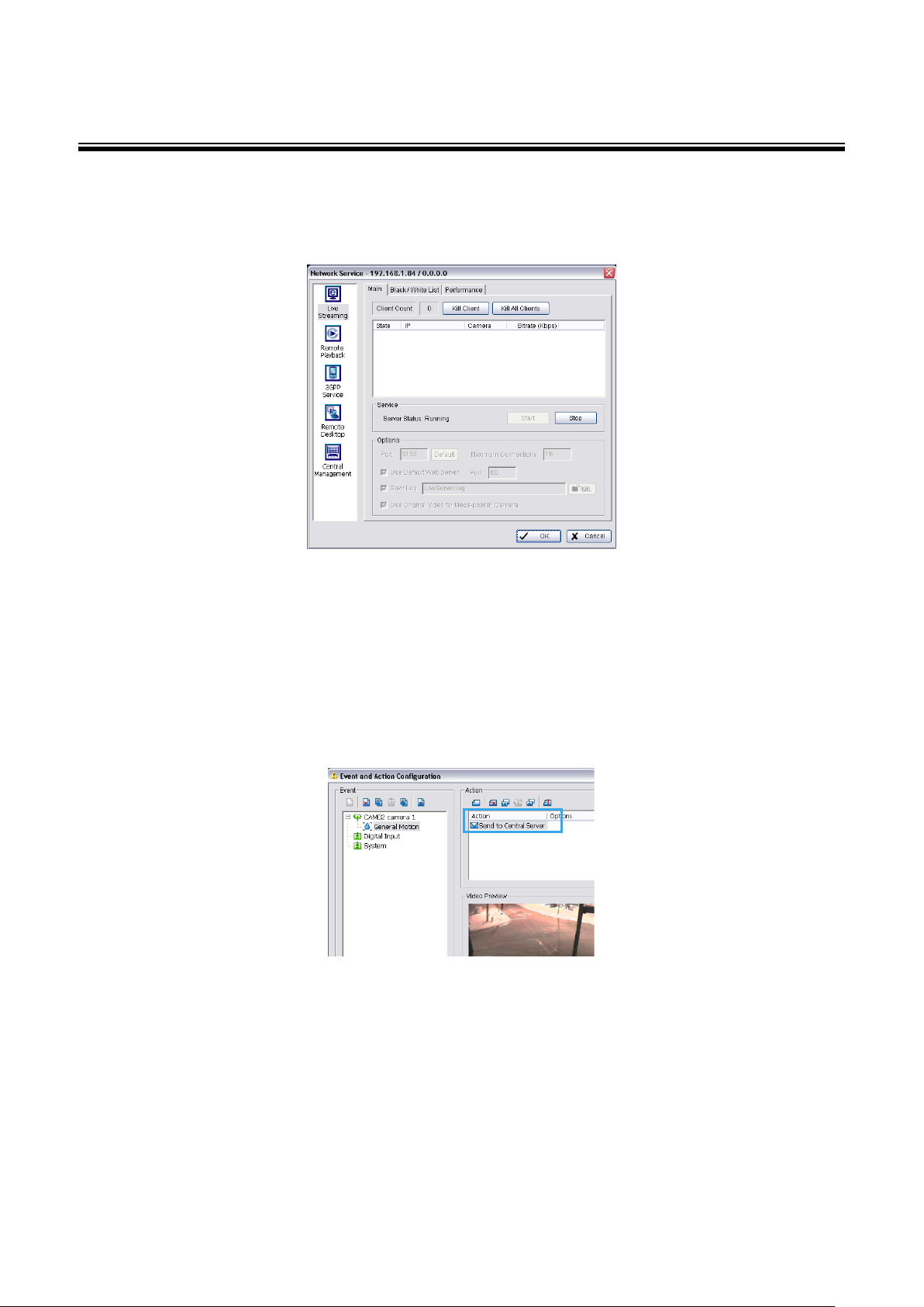
2. In Config, select Network Service, and set up the follow ing serv ice s:
Live Streaming and Central Management. These services are essential to run the CMS system. Please start
these two services.
Remote Playbac k. This service enables recorded video viewing and remote playback. This service is also
responsible for providing data for client backup. Ensure this service works, please also Start Recording
Schedule to record video.
Remote Desktop . This serv ic e enabl es rem ote conf iguration of the main console.
3. Select Guard.
4. In the Event and Action Configuration window, configure alarm events and insert the action Send to Central
Server for events that you want to appear on the CMS system.
5. Click OK to return to the main console.
6. In the Start Menu, select Start Smart Guard System to start detecting events.
SQL Server
To configure SQL Server:
1. In the Start menu, point to All programs, point to Microsoft SQL Server 2005, point to Configuration Tools, and
then select SQL Server Configuration Manager.
17
Page 18
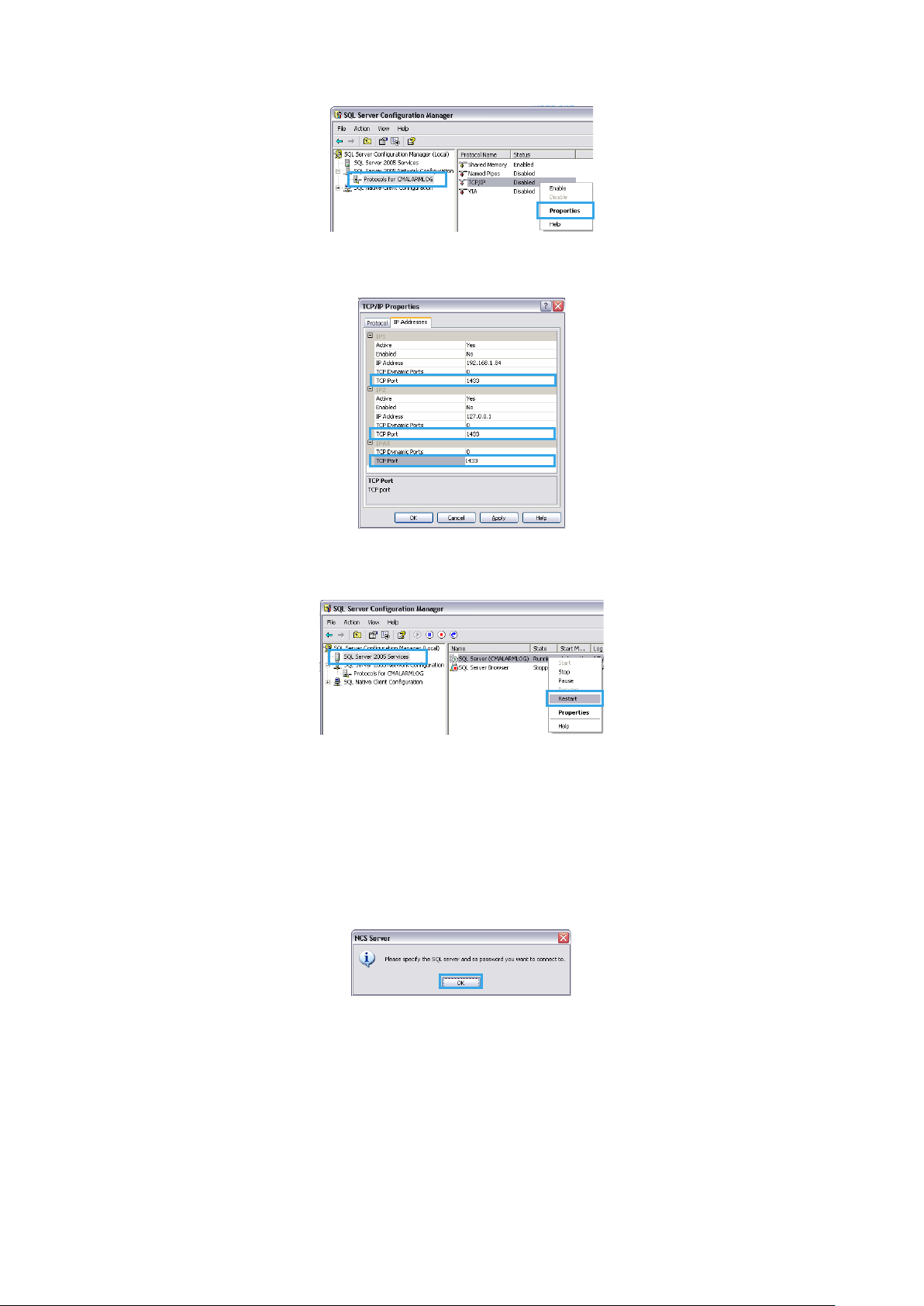
2. In the SQL Server Configuration Manager window, select Protocols for CMALARMLOG, right-click TCP/IP and
then select Enable to enable TCP /IP protoco l.
3. Double-click TCP/IP, then in the TCP/IP Properties window select the IP Addresses tab.
4. Enter 1433 as the TCP port in IP1, IP2, and IPAll, and then click OK.
5. In the SQL Server Configuration Manager window, select SQL Server 2005 Services, right-click SQL Server
(CMALARMLOG), and then select Restart.
6. Ensure that any firewall allows access through port 1433.
CMS Alarm Server
To configure CMS Server:
1. In the Start menu, point to All programs, point to Central Management Server, and then select CMS Server.
2. In the CMS Server dialog box, click OK. This is only required the first time you start CMS server.
18
Page 19
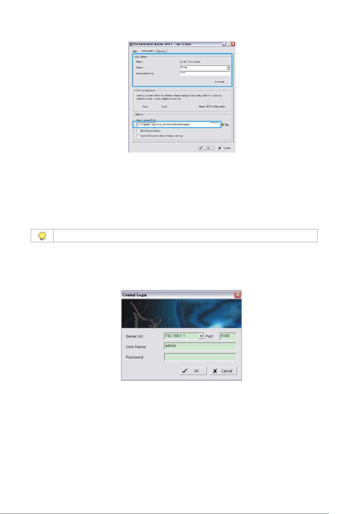
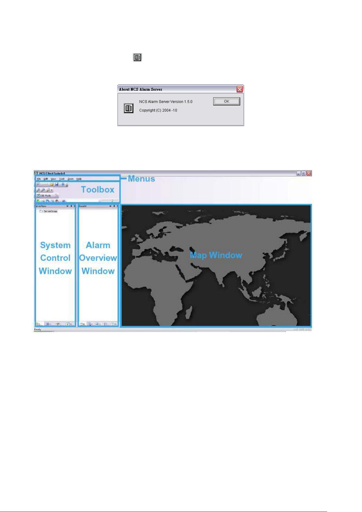
3. The configuration of CMS Alarm Server.
In the Configuration tab of Central Server window, enter the IP address of the SQL Server, and then enter and
confirm the password set when installing SQL Server. (see page 10)
Specify a URL at which to store all alarm images.
Select Run CMS Server when Windows starts up if you want CMS Server to startup automatically at Windows
startup
4. In the Main table of this window, check the server has been Start and click OK.
The CMS Server must be executed before the CMS Client can be executed.
CMS Client
To configure and execute the CMS Client:
1. In the Start menu, point to All Programs, point to Central Management Client, and then select CMS Client.
2. In the Central Login window, enter the IP address and port of the CMS Server PC. The default port is 5180.
3. Enter a user name and, if required, a password. The default user name is admin and the default password is
empty.
4. Click OK.
To activate software license key(s)
1. Open License Manager Tool i n Help menu.
2. Select Activate tab, check the CMS system in On line network environment.
3. Insert the SN, SN file or dongle to activate license.
19
Page 20
4. After software license is activated successfully, please restart CMS Client.
Please refer to page 59 for advanced settings.
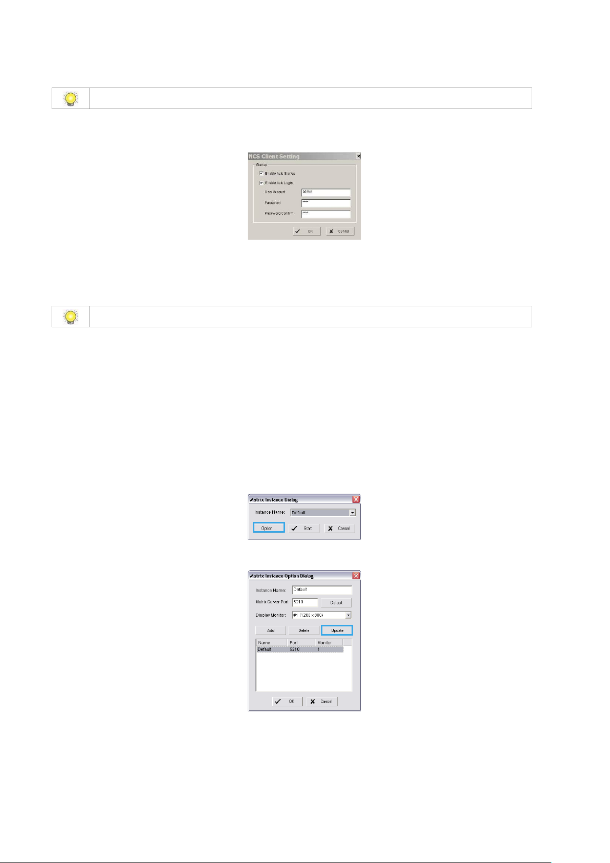
To start up CMS Client automatically:
1. In the Edit menu, select CMS Client Setting.
2. In the CMS Client Setting window, select Enable Auto Startup and Enable Auto Login
3. Enter a user account and, if required , a password.
4. Click OK.
Please refer to page 26 for advanced settings.
CMS Matrix
To execute a single matrix display:
1. In the Start menu, point to All Programs, then point to Central Management Client or Central Management Matrix,
and click CMS Matrix.
To configure the first matrix in a multiple matrix system:
2. Ensure that the PC is configured to use multiple monitors.
3. In the Start menu, point to All Programs, then point to Central Management Client or Central Management
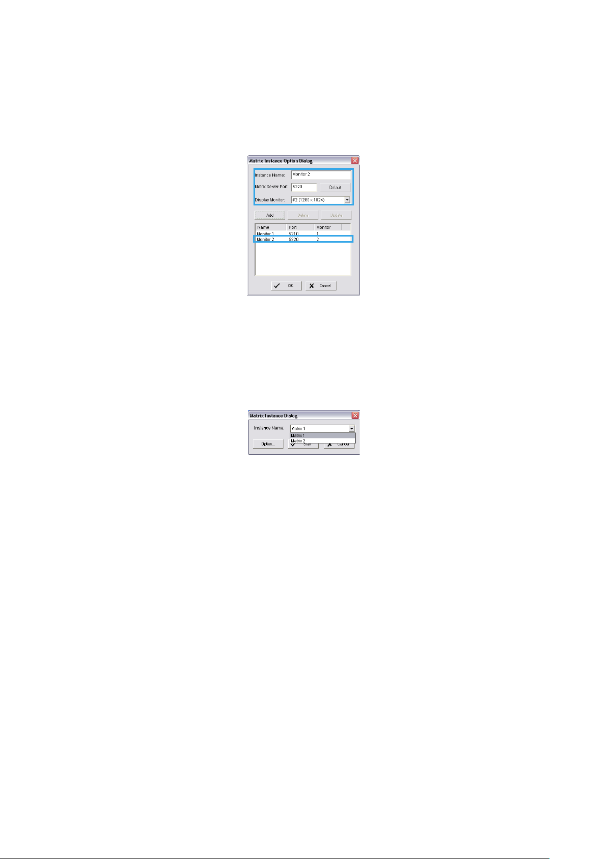
Matrix, and click CMS Matrix.
4. Click on Option to open Matrix Instance Dialog.
5. In the Matrix Instance Option Dialog window, select Default from list table.
6. Enter a matrix name, for example Monitor 1, in the Instance Name text box, leav e the port at the default set ting of
5210, select the #1 monitor from drop-down list, and then click Update to update modification.
20
Page 21
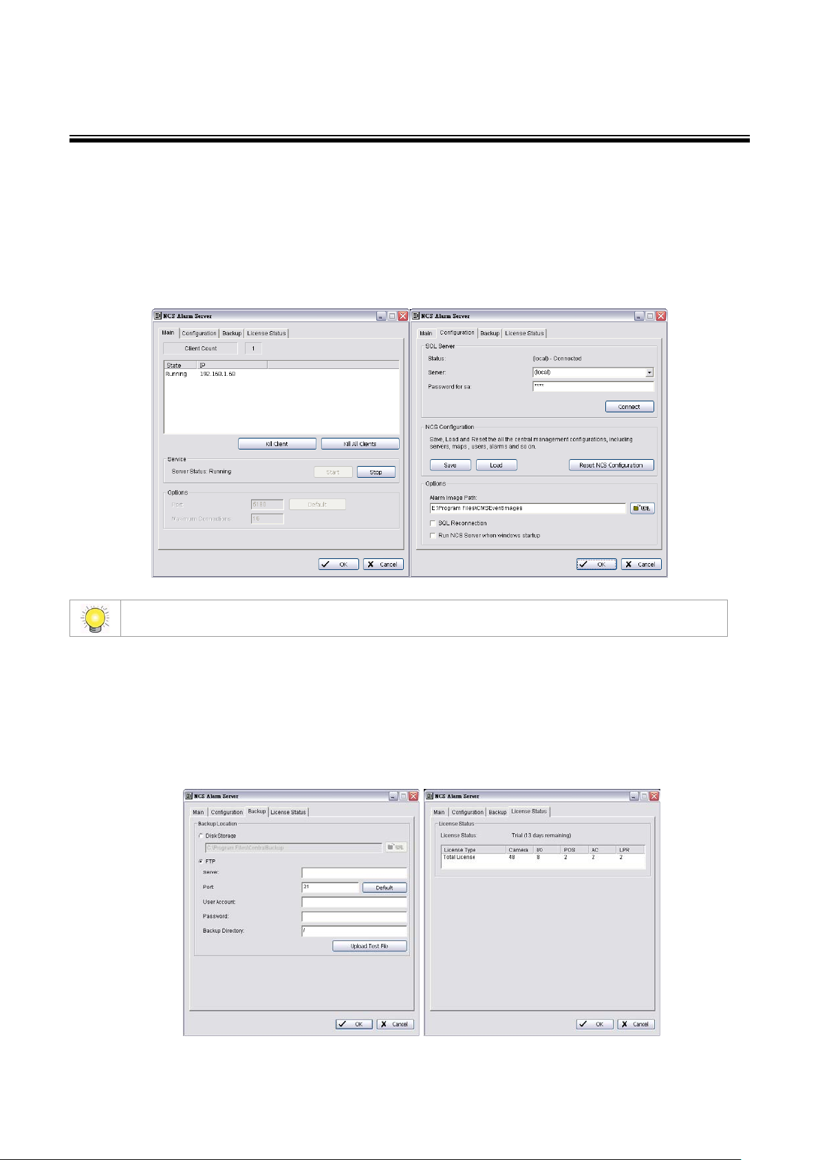
To configure the second and subsequent matrixes in a multiple matrix system:
1. In the Matrix Instance Option Dialog window, enter a matrix name, for example monitor 2 in the Instance Name
text box.
2. Enter port number 5220.
3. Select the #2 monitor from drop-down lis t, and then click Update to update modification.
4. To configure a third and a fourth monitor, repeat steps 1-3 naming the matrix instances as appropriate (for
example monitor3, monitor4), entering the port number (5230 for a third monitor and 5240 for a fourth), and
selecting the appropriate monitor.
5. Click OK to save all configuration of Matrix.
To execute a matrix in a multiple matrix system:
1. Ensure that the matrixes have been configured as described above.
2. In the Matrix Instance Dialog window, choose the matrix you want in the drop-down list, and then click Start to
start Matrix view.
3. Repeat steps 1 and 2 to execute each monitor.
21
Page 22
CMS System Overview
CMS Server Window Introduction
The CMS Server features four main tab windows, including :
The Main window controls the start/stop CMS server as well as the client connection through kill client/kill client all
options.
Under the Configuration window you may setup the connection between SQL Server and CMS Server,.
Restoring CMS Configuration will not clear the setting of SQL Server.
CMS Server enables backing up alarm records at a local hard drive or to FTP servers. Define a storage location for
video backups under the Backup window.
You may select between two storage locations. Choose Disk Storage for local hard drives or DAS, or choose FTP to
backup to FTP servers.
The License Status window displays current available licenses in the system.
22
Page 23
By double clicking on the server icon from the Taskbar you can access CMS Server settings directly.
You can also check the version of your system or stop the service by right clicking on the icon and clicking About or
Exit.
CMS Client Window Introduction
The default CMS Client window placement is as the following figure, including t hree ma in windows, four toolbars, and six
menus.
Three Main Windows are:
System Control window: This window includes the Server List, Map List, Configuration, Matr ix List and View
Group List sub-windows. Administrators can configure the CMS system in this window when the system is in Edit
Mode. (See Part 2: Administrator Functions (Setting Up the CMS System)
23
Page 24
Map window: This window shows all maps and device indicators. For administrator setup, see page 32. For day to
day use, user can view the video, show device information, query and manage alar ms from the indi cators (please
refer page 75).
Alarm Overview window: The default Alarm Overview window contains the Recent, Real-Time, Output, Output 2,
and Message Log tabs, which allow users to manage alarms (see page 65).
Six menus are:
The File menu: This menu has functions use to commit to CMS Server, save/load CMS Client Configuration, and
Logout/Exit CMS system.
The Edit menu: It allows administrator add New Object to configuration sub-window of System Control Window,
Import Indicator Image, setup Server configuration (refer Central Server Configuration Window section of page 44)
on Edit mode; and allows all user to setup Map Display setting of Map windows, Alarm Log setting of alarm
overview windows, and setup Joystick to control Matrix.
The View menu: This menu has options to setup the appearance of CMS Client window.
The Tools menu: This menu has five tools to help user easy to get information for Main Console, manage alarms,
and view live and record videos.
The Zoom menu: User can control and adjust map appeara n ce (see page 75).
The Help menu: The menu provides the version information of CMS Client.
24
Page 25

The toolbars are:
The Standard toolbar: The functions accessed by this toolbar are: toggle Edit Mode/Operate Mode (see page 28),
committing configuration changes to the server (see page 28), importing/exporting CMS Client software
configuration (see page 58), and displaying version information (see page 97).
The Map toolbar: The functions accessed by this toolbar are used to adjust map appearance (see page 75).
The Operate toolbar: The functions accessed by this toolbar help users in day to day use of the CMS Client. For
more information, see page 64.
The Status toolbar: Quick links to SQL Server Status and Central Backup Status can be found here.
The Search toolbar: The functions accessed by this toolbar include functions involved in searching (see page 76).
Standard Map Operate Status Search
25
Page 26
CMS Client Setting
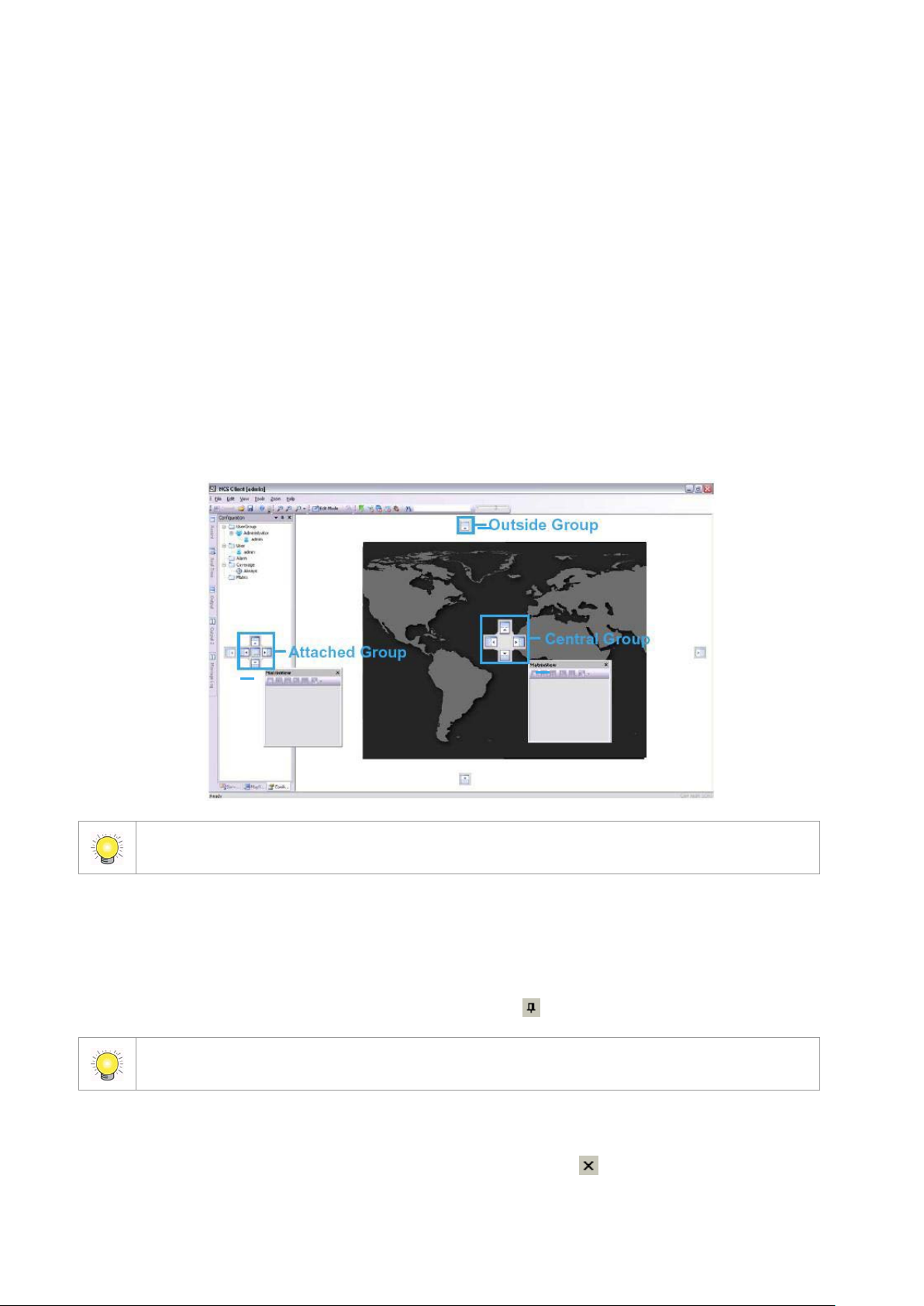
You are able to configure functions including auto startup, auto login, auto reconnection, instant playback and client
recording under this window. Go to the Edit menu – CMS Client Setting.
Startup: Check to enable auto startup or auto login.
Reconnection: Check to enable auto reconnection to CMS Server / CMS Matrix when connection is lost.
Record Setting: Check to enable alarm triggered local recording on CMS client. You may customize pre/post
record time and auto rec ycle settings.
Instant Playback Setting: Configure pre/post playback length under instant playback windows.
Miscellaneous: Check Show central ID on server list and matrix list to display server / device / matrix ID
number on server and matrix lists. This is mainly for Joystick control. For details, please refer to p. 92.
To enable Recording on CMS Client or instant playback you MUST also start recording from Main
Console. CMS cannot access playback if Main Console has not recorded video.
Customizing Client Appearance
The appearance of the CMS Client is customizable. The System Control and Alarm Overview windows and their nine
associated tab display windows can be moved or removed to four appearance types:
Floating: A floating window can be moved to any position on the screen.
Docking: A docking window is aligned with one of the four edges of the application window.
Auto Hide: Docking windows can be set to AutoHide. The window then displays only when you point to the area
of the screen where the window is docked.
Hide: Hide the windows can be removed from screen.
Toolbars also can be moved or removed. The outlook of the client can also be changed to various preset styles.
To restore appearance back to default, please go to View menu and click on Reset Window Placement.
26
Page 27
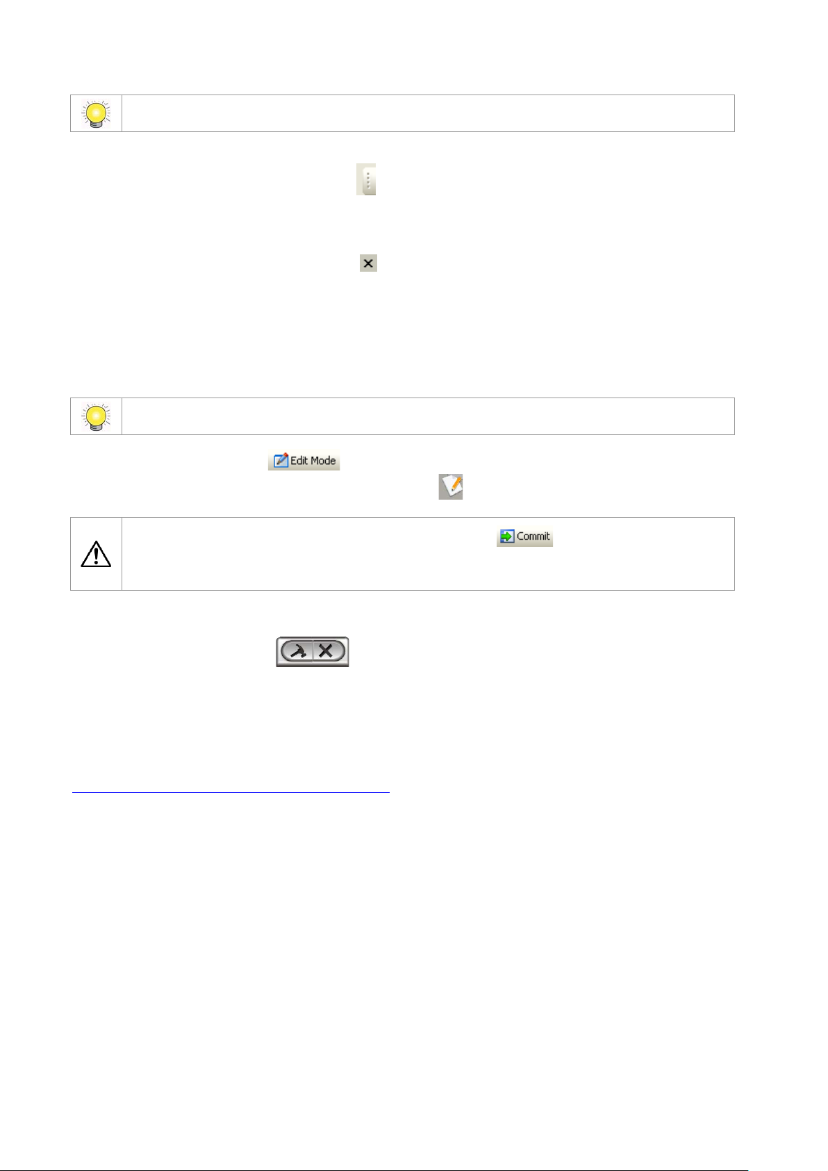
To move a main window:
Click the title bar at the top of the window and drag it to the position you want. If you want it to dock at one of the edges of the
CMS Client window, drag it to one of the direction arrow buttons. There are three direction arrow buttons groups of different
windows (refer next page):
The Central group of Map Window, it allow move window to four edge of Map window.
The Outside group of CMS Client Window, it allow move window to four edge of Map window.
The Attached group of individual window, it allow move window to four edge of individual window and move to be
an associated tab display windows.
To move an individual tab display window:
Right-click on a tab and select Floating, or c lick directly on the tab and drag the window to the position you want. If you
want it to dock at one of the edges of the CMS Client window, drag it to one of the blue direction arrow buttons. The Auto
Hide function can now be applied to that tab window individually.
To move an individual tab display window to a main window:
Right-click on a tab and select Docking, or click directly on the tab and drag it to a tab bar in a main window.
These direction arrow buttons groups only appear when CMS Client preset style set as Office 2003 / Visual
Studio.NET 2005 / Office 2007
To Auto Hide a window (only available when window is docked):
Either:
Right-click in the window and select Auto Hide.
Or:
In the title bar for the window, click the Auto Hide toggle button .
The Auto Hide function applies to all tab windows in a main window. If one of the tab windows in a main
window is set to Auto Hide, all the other tabs will also Auto Hide.
To close an individual tab display window:
Right-click on a tab and select Hide or click directly on the Close Window button on the top right corner of the window.
To display the window again, go to the View menu, point to Toolbars, and then check the window you want to show.
27
Page 28
Another way to close a window is to uncheck a box in the Toolbars menu.
To move a toolbar:
Click on the double line on the left side of a toolbar and drag it to the position you want.
To hide or display a toolbar
Go to the View menu, point to Toolbars, and then uncheck or check the toolbar you want to hide or show. And if user drag
to as an individual menu in window, simply click the button on the top right corner of the menu to close it.
To change the look of the CMS Client to a preset style:
In the View menu, point to Application Look, and choose one of the following preset application looks: Office 2000 / Office
XP / Office 2003 / Visual Studio.NET 2005 / W indows XP / Office 2007
System Operate Mode/Edit Mode
To carry out most adminis trator functions, you need to be in Edit Mode.
Press the Edit Mode toggle button to enter Edit Mode, and press it again to exit Edit Mode. When in Edit
Mode, the CMS Client will not receive alarms. A flashing indicator reminds you that you are in Edit Mode.
Any changes made to the s ystem must be saved with the Commit button. When administrators
click the Commit button to save changes, other users will be disconnected from the CMS server and will
need to log in again.
CMS Matrix Window Introduction
Move Mouse to right-down area, the icon would auto appear. User can edit/exit the Matrix, further option
please see page 54.
SQL Server Introduction
CMS system is use SQL Server 2005 Express of Microsoft free application software as database. recommend user to use
Microsoft SQL Server Management Studio Express to backup SQL Server. Please refer the web site of Microsoft
http://technet.microsoft.com/en-us/library/ms365247.aspx .
28
Page 29

Part 2: Administrator Functions (Setting Up the CMS
System)
This section describes functions and operations of the administrator to set up the CMS Client software system while in Edit
Mode. Please follow this section to setup Servers/Devices, Maps, Servers/Devices on Map, User Groups and Users
Coverage, Alarms, and Matrix s y s tem.
,
29
Page 30

Servers/Devices
The CMS Client provides the ability to monitor unlimited cameras and input/output devices through unlimited Main Console
servers. For convenience, Main Console servers and their related devices are organized into groups. The default top-level
group is called ServerGroup. Child groups can be added to this in a hierarchical structure.
To carry out the functions described below, you need to be in Edit mode and Commit after setup (see
page 28).
The license of the software should be registered first before operating the formal version of CMS System.
Execute the License Management Tool in Help>License Manager to activate the license from a dongle or serial
number allocated with the CMS software package, or de-activate the license then use it on another PC to activate it
again. Please refer to page 59 for details on how to configure the License Management Tool.
Adding/Editing/Removing Server Groups
To add a server group:
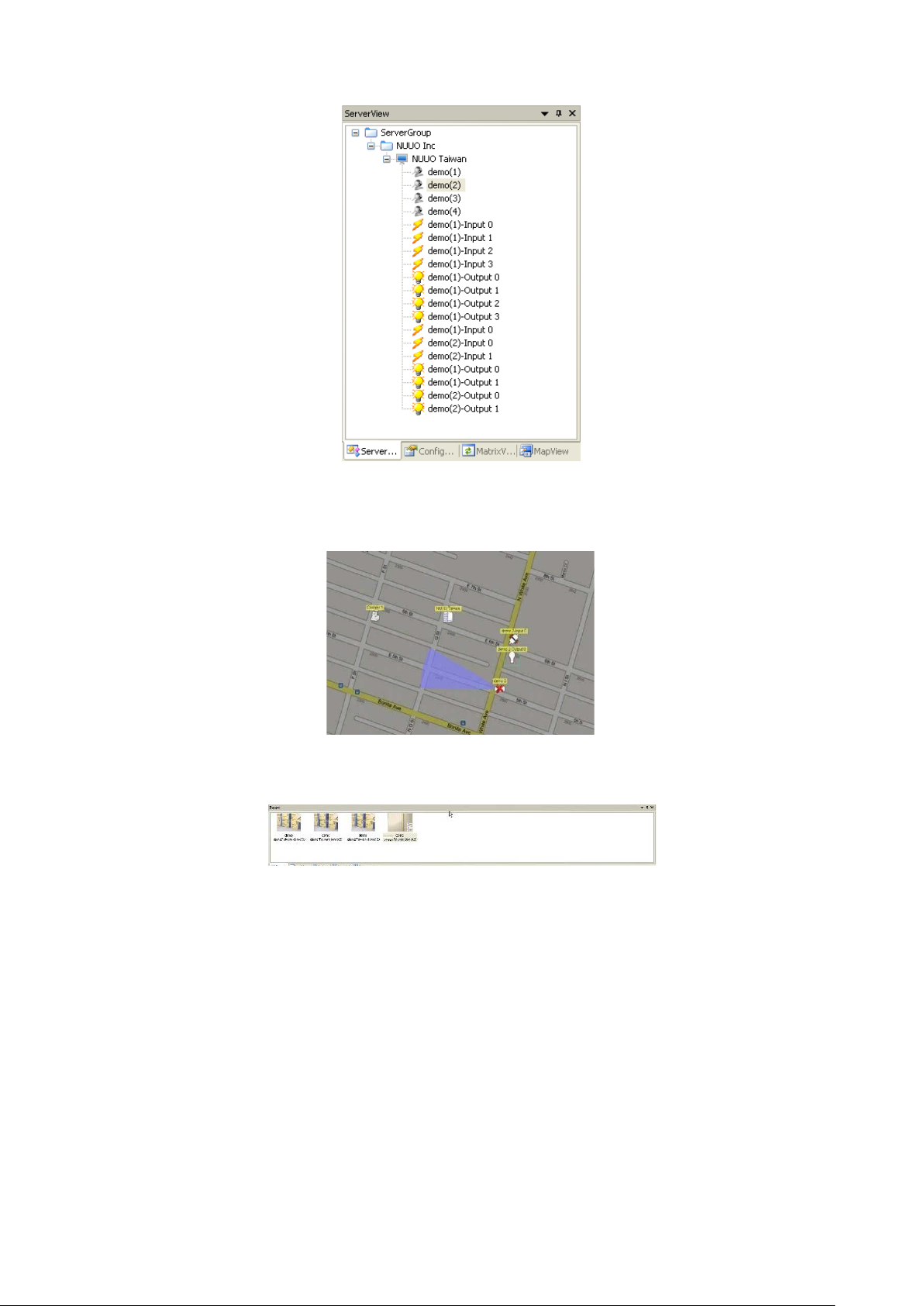
1. Ensure that the client is in Edit Mode and that the ServerView tab is selected.
2. Right-click on the ServerGroup icon at the top of the window, then click Add Group.
3. Enter the group name, then click OK.
4. The group you added appears in the tree structure of the ServerView window.
To edit a server group name:
1. Right-click on the server group icon for the group you want to edit.
2. Select Settings.
3. Enter the name you want, then click OK.
To remove a server group:
1. Right-click on the server group icon for the server group you want to remove.
2. Select Delete and click Yes at the confirmation prompt.
Adding/Editing/Removing Servers
Servers can be added to any server group. When a server is added, the devices on it must be synchronized with the CMS
Client (See page 31). This procedure ensures that the cameras, input /out put dev ice s, and meta dat a dev ices on the server
are available for monitoring.
To add a server:
1. Ensure that the client is in Edit Mode and that the ServerView tab is selected.
2. Right-click on a server group icon , then click Add Server.
3. Enter the server details, then click OK. The Central Managem ent Port should be the same as setup in Main
Console server.
4. The server you added should appear in the tree structure of the ServerView window.
To edit settings of an existing server:
1. Go to server view under E dit Mode.
2. Right-click on an existing server and choose Settings…
30
Page 31

You must have enough licenses for the devices, otherwise the
3. Click OK after configuration is done.
Licenses for all servers and devices (cameras, I/O devices and metadata devices) need to be ac tivated via
CMS Client. (See Page 60)
If you enter the Central Management port and cli c k Detect, the CMS system will auto-detect the ports for
Live Streaming, Remote Playback and Remote Desktop.
Click the Server Info button to open a Server Information window, and the Server Information will be
displayed on the Alar m deta il w indow when an alarm is active.
To add contacts to the server:
1. Click on Add under Server Configuration.
2. Complete the required info and click OK.
To synchronize server devices:
Right-click on a server icon , then click Synchronize Device. Then, all
cameras, metadata and input/output devices of Main Console server will
appear and be available for monitoring.
devices without licenses will show disable icon . In the Tool menu,
select Server Summary to check the license status.
To edit server settings:
1. Right-click on a server icon , then click Settings.
2. Enter the required settings, then click OK.
To remove a server:
1. Right-click on a server icon .
2. Select Delete and click Yes at the confirmation prompt.
You may sort servers under server groups or devices under servers according to name or type. To do this
right click on any server group or server under Edit mode and choose Sort by… Name or Type. You may
also drag and drop icons to rearrange order manually.
31
Page 32

Maps
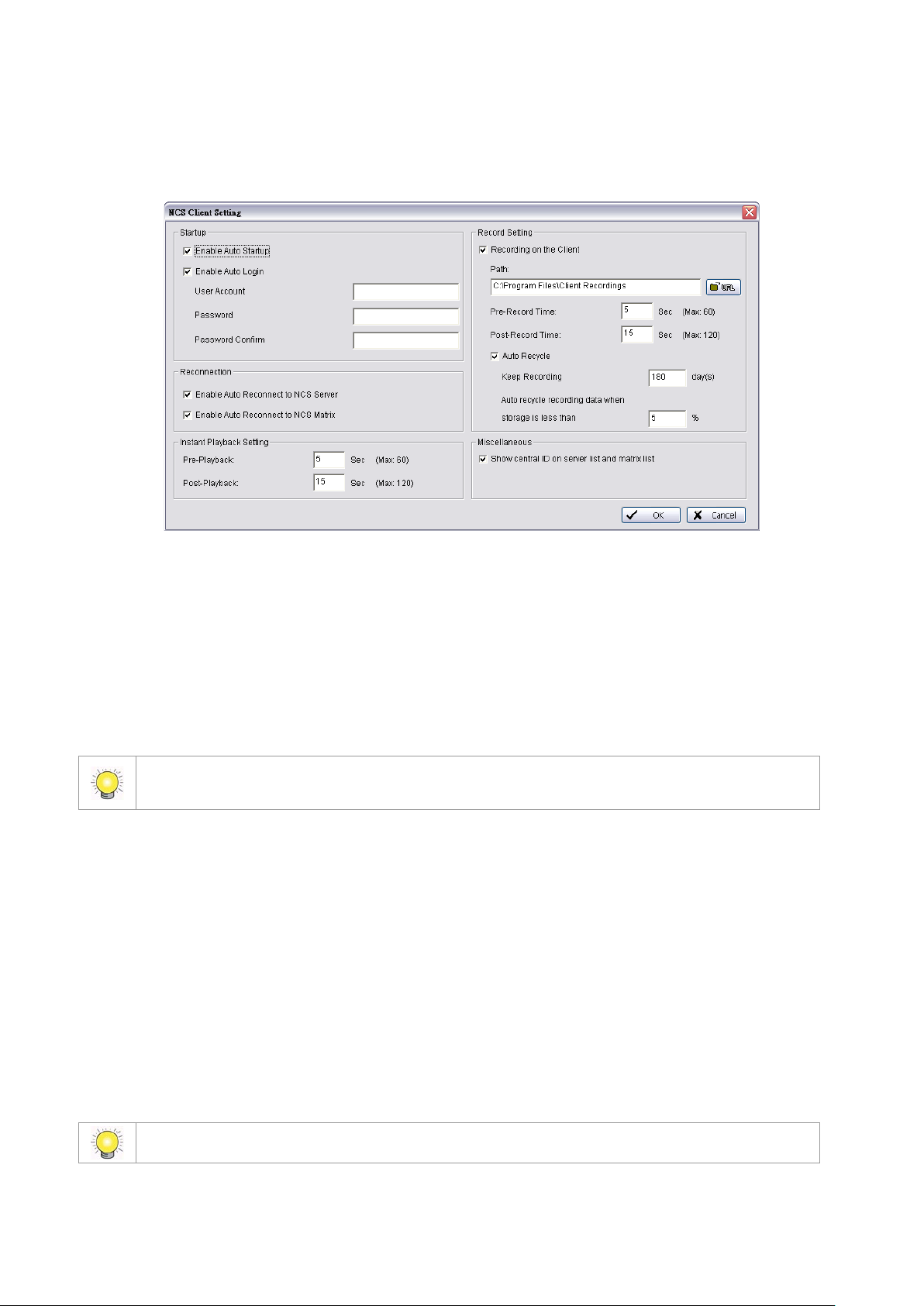
The Map window displays indicator icons representing the devic es and servers that the CMS client monitors. They are
shown against map back grounds. This enables quick and easy control and monitoring of devices according to their location.
Multiple maps of different locations and at different scales can be used, as described below. To change the size, pan
settings and brightness of map graphics, see page 75.
To carry out the functions described below, you need to be in Edit Mode and Commit after setup (see
page 28).
Map Hierarchy
Maps can be layered in a hierarchical structure. Typically, the top–level (parent) map is at a large enough scale to cover the
geographical areas of all the lower-level (child) maps. Each child map is assigned an icon on the parent map. Clicking a
child map icon shows the child map in the Map window. Multiple levels of child maps can be defined.
The default top level map is provided by . To change this, see the section To edit map settings below.
Adding/Editing/Removing Maps
To add a child map to a parent map:
1. Ensure that the client is in Edit Mode and that the MapView window is selected.
2. Right-click on the icon for the parent map , then click Add Map.
3. Enter the required details.
4. If you do not want to use the default indicator image, please manual import another image and set to default (For
information on importing indicator images, see page 33.).
5. Click OK. The map you added appears in the tree structure of the MapView window.
6. The map indicator appears on the parent map. Drag it to the position you want.
To edit map settings:
1. Right-click on a map icon , then click Settings.
2. Enter the required settings, then click OK.
To remove a map:
1. Right-click on a map icon .
2. Select Delete and click Yes at the confirmation prompt.
You may sort maps and devices on the map list according to name or type. To do this right click on any
map under Edit mode and choose Sort by… Name or Type. You may also drag and drop icons to
rearrange order manually.
32
Page 33

Servers/De vices on Map
Each Main Console server or device can be ass igned to a map. An indicator for the Main Console server or device is
displayed on the map at the position you choose. This allows quick and easy control and monitoring. You can control the
orientation of indicators as well as the appearance of accompanying text and the information it shows. The CMS Client
software comes with default indicator images, but you can also import your own.
To carry out the functions described below, you need to be in Edit Mode and Commit after setup (see
page 28).
Importing Indicator Images
To import an indicator image:
1. In the Edit menu, select Import Indicator Image.
2. From the drop-down list, select the type of indicator image you want to import.
3. Click Import, browse to the required image file, and open it.
4. Click OK.
If you want to set a specific image as the default for a file type, select the image, then select the Default
checkbox.
Adding/Removing Device Indicators
There are two ways to add device indicators to a map: MapView display and ServerView.
To add device indicators to a map in MapView:
1. Ensure that the client is in Edit Mode and that the MapView window is selected.
2. Click on the map icon for the map you want to add an indicator to. This displays the map.
3. Right-click on the map ic on.
4. Click Add Server Indicator, Add Camera Indicator, Add Metadata Indicator or Add I/O Indicator, as required.
5. From the drop-down list, select a device.
33
Page 34

7
6. Choose an indicator.
7. When the device is a camera select Show Coverage Area to set the Range and Radian.
8. Click Apply to… if you need to apply settings to other camera indicators.
9. Click OK.
10. The device indicator will appear on the map. Drag it to the required location.
To drag a device indicator to a map from ServerView:
1. Ensure that the map you want is displayed.
2. Click on the ServerView window.
3. Directly drag a device to the desired location on the map.
If you are in MapView and click on a device which has already been added to a map, the map for that
device will be displayed.
To remove a device indicator from a map:
1. Right-click the indicator.
2. Click Delete.
3. Click Yes in the confirmation w indow .
Edit Device Indicators
An indicator image can be rotated, mirrored, or changed. The image can also be set to refer to a different device than the
one originally chosen.
To rotate a device indicator to a preset angle:
Once a device indicator has been added or dragged to a map, the indicator image can be rotated. This is useful to show
which direction a camera is pointing.
34
Page 35

1. Right-click the indicator or right-click the device from MapView.
2. Click Rotate and choose an angle (preset angle 0, 45, 90, 135, 180, 225, 270, or 315 degrees).
The radian, range, color and area of Camera Indicator can be set to show camera coverage.
To rotate a device indicator to an arbitrary angle:
1. Right-click the indicator or right-click the device form MapView, or click icon from Edit toolbar.
2. Click Rotate Arbitrary.
3. Use the rotation handle to rotate the indicator to the desired angle, then click to fix the angle.
4. Click Rotate Arbitrary again to close this option.
To mirror a device indicator:
Indicator images can be mirrored (flipped horizontally) so that a mirror image is displayed. One use would be to show in
which direction a camera is pointing. For example, a default image m ay show a camera pointing left.
1. Right-click the indicator or right-click the device form MapView.
2. Click Mirror.
3. Mirroring would then have it facing right.
The mirror command is a toggle. To un-mirror a previously mirrored indicator, follow steps 1 and 2 again.
To change a device indicator image:
1. Right-click the indicator or right-click the device form MapView.
2. Click Settings.
3. Select the indicator image you want, then click OK.
To import a new indicator image, see page 33.
To remove a device indicator from a map:
1. Right-click the indicator or right-click the device form MapView.
2. Click Delete.
3. Click Yes in the confirmation w indow .
35
Page 36

Coverage
Coverage is a defined period or periods of time. This is used for the following purposes:
To define the times a user can log in to the system and use the CMS client. This coverage is applied according to
the local time of the CMS Client.
To define the times that an alarm is active. This coverage is applied according to the local time of the source Main
Console server.
To carry out the functions described below, you need to be in Edit Mode and Commit after setup (see
page 28).
Adding/Editing/Removing Coverage
To add a coverage:
1. Ensure that the client is in Edit Mode and the Configuration window is selected.
2. Right-click on the Coverage folder icon , then click Add Coverage.
3. In the Coverage Dialog window, enter a coverage name and, if you want, a coverage description.
4. Choose a coverage mode:
General is for regular coverage periods.
Spec i fi c Day means that this coverage applies to a specific date only. Choose the date from the drop-down list.
5. Select the time periods you want for this coverage.
Drag over the time periods you want. Selec ted periods appear in blue.
To remove periods, select Remove Time Period and drag over the periods you want to remove.
To clear all selected periods, click the Clear All button.
6. Click OK. The coverage you added appears in the tree structure of the Configuration window.
You can also add a coverage from the Edit menu by pointing to New Object, clicking o n Coverage then
following steps 3 – 6 above.
To edit a coverage:
1. Right-click on the coverage ic o n for the coverage you want to edit.
2. Select Edit Coverage.
3. Edit the settings as required.
4. Click OK.
To remove a coverage:
1. Right-click on the coverage icon for the coverage you want to remove.
2. Select Delete Coverage and click Yes at the confirmation prompt.
36
Page 37

Alarm Image
Alarm Management
User Groups and Users
System administrators can control who can use the CMS client, when they use it, their ability to perform various functions,
and which devices they can access. Privileges are assigned via user groups. For each user group, an administrator can
define permitted functions as well as which devices the users in that group can access. Password control, perm i tted access
times (see page 36), and a matrix profile (see page 47
To carry out the functions described below, you need to be in Edit Mode and Commit after setup (see
page 28).
Adding/Editing/Removing User Groups
To add a user group:
1. Ensure that the client is in Edit Mode and that the Configuration window is selected.
2. Right-click on the User Group folder icon , then click Add User Group.
) are configured in the settings for each user.
3. In the User Group Configuration window, enter a group name and a group descripti on if required.
4. In the Function Privilege area, select the privileges for members of this User Group:
Alarm Management – allows users to change alarm status on the Alarm Management window (see page 65).
37
Page 38

View Alarm Image – allows users to see a snapshot from the camera as an icon in the Recent display (see
page 65) and view snapshot on Alarm detail Window.
Open Live Video – allows users to open a live video window to view image of the camera and related devices
from the Alarm Detail window or by right-clicking on a camera indic ator.
Open/Backup Recorded Video – allows users to open or back up recorded video of the camera and related
devices from the Alarm Detail Window or by right-clicking on a camera indicator.
PTZ Control – allows users to control the PTZ (pan, tilt, zoom) settings of compatible cameras. This option onl y
works when users also have Open Live Video authority. Priority of PTZ control of the user group is defined by
numbers 1-10, with 1 for the highest priority. Users with higher priority can obtain PTZ control from other users.
Control Digital Output – allows users to control digital outputs such as alarms. This option only works when
setting IO devices as related devices in Alarm setting (see page 42 ).
View and Search Metadata transaction – allows users with authorization to sear ch metadata transactions.
Remote Desktop – allows users to open a remote desktop.
5. In the Device Access area, choose the devices which members of this User Group will be able to access . If the
devices have not been enabled in Device Access table, users still don’t have allow to use above functions.
6. Click OK. The user group you added appears in the tree structure of the Configuration window.
You can also add a user group from the Edit menu by pointing to New Object, clicking on User Group
then following steps 4 – 6 above.
For quick add a new User Group, please use Insert Copy option by right-click on the User Group which
you want to copy.
To edit a user group:
1. Right-click on the User Group icon for the user group you want to edit.
2. Select Edit User Group.
3. Edit the settings as required.
4. Click OK.
To remove a user group:
1. Right-click on the User Group icon for the user group you want to remove.
2. Select Delete Group and click Yes at the confirmation prompt.
Adding/Editing/Removing Users
Add new users and modify or remove existing users. You may choose to add Central Users d irectly in the system or
import users from MS Active Directory (MSAD) as Windows Users.
To add a Central User:
1. Ensure that the client is in Edit Mode and the Configuration window is selected.
2. Right-click on the User folder icon , then click Add Central User. The User Configuration window
appears.
38
Page 39

3. In the User Configuration window, enter a user name.
4. If password access is required for this user, enter and confirm a password.
5. Enter a description if needed.
6. If you want this user to receive auto alarm notifications by emai l or SMS, enter the email address and/or Cellphone
number.
7. Choose a user group, a c overage (see page 36), and a matrix initial view group (see page 47) from the drop-down
lists. The coverage here is based on the CMS Client’s lo cal time.
8. Click OK. The user you added appears in the tree structure of the Configuration window.
You can also add a Central user from the Edit menu by pointing to New Object, c licking on User then
following steps 3 – 8 above.
To edit a Central user:
1. Right-click on the user icon for the user you want to edit.
2. Select Edit User.
3. Edit the settings as required.
4. Click OK.
To remove a Central user:
1. Right-click on the user icon for the user you want to remove.
2. Select Delete User and cl i ck Yes at the confirmation prompt.
Enable Disable User Account option on User Configuration window also can reject this user account to
login CMS system.
You may sort users and user groups on the configuration window according to name. To do this right click
on User or User Group under Edit mode and choose Sort by… Name. You m ay also drag and drop icons
to rearrange order manually.
39
Page 40

To add / remove / synchroniz e a Windows User:
1. Right-click on the User folder icon , then click Add/Remove/Sync. Windows User. The Select Group /
Select User window appears.
2. Check users or folders under Select Active Directory user(s) and cl ic k OK to add Windows Users.
Click Select All to check all available users and folders, or click Deselect All to uncheck all users.
Group Mapping:
Selected Windows users will be grouped according to default mapping:
MSAD Group Central User Group
Administrator
No Group
Other Groups
Administrator
Default User
Automatically add a new user
group with the same name
You may further modify group setting for each user manually. Please refer to edit a Central User on page
39 for details.
Editable columns for Windows Users include Email, Phone Number, User Group, Coverage, Initial
View Group and Disable User Account.
3. Synchronization results will be displayed for confirmation. Please refer to the default solution for all conflicts:
New accounts added from AD domain
40
Add to Central System
Page 41

Newly added account from AD domain conflicts
Accounts from AD domain removed
Account description modified
Encountered admin account
with existing central user account
Current logged in account removed
Delete from Central System
Update description
Skip admin account
Replace Central user account
Skip login user
4. Uncheck items to skip applying solution to CMS Client user account settings.
For example, if you uncheck an “Add to Central System” solution, the new account will not be added to CMS
Client’s user account list.
Instead of manually adding and updating Windows users, you may also c onfigure the system to
automatically synchronize all Windows users at a specific period.
To configure automatic synchronization on Windows Users:
1. Right-click on the User folder icon , then click Auto. Sync. Windows User Setting. The Automatically
Synchronized Setting window appears.
2. Check Automatically synchronize Windows users.
3. Configure synchronized period to start every ___ days.
4. Define synchronized time to decide what time the synchronization should start.
5. Click OK.
Auto synchronization will apply all default solutions to conflicts.
41
Page 42

Alarms
The alarm functions of the CMS Client can be configured to monitor many different events triggered by cameras, input
devices, output devices, and servers.
To carry out the functions described below, you need to be in Edit Mode and Commit after setup (see
page 28).
Adding/Copying/Edit ing /Re mov ing Alarms
To add an alarm:
1. Ensure that the client is in Edit Mode and the Configuration window is selected.
2. Right-click on the Alarm folder icon , then click Add Alarm.
3. In the Alarm Configuration window, enter an alarm name and alarm descriptio n.
4. Choose an alarm priority and an alarm owner from the drop-down lists.
5. Choose from the following settings:
Choose a coverage (default coverage is Always). The coverage here is based on the alarm source device’s local
time.
Enter a rearm interval. If the rearm interval is too short (default interval is 5 sec.), multiple alarms may be
triggered by certain events such as motion.
42
Page 43

You can pick from two Close Alarm options. If you want the alarm to close automatically when the triggering
event ends, check Auto Close Alarm. You can also set a timer for the alarm to close automatically after a
couple seconds.
If you want to record video locally whenever this alarm is triggered, check Recording on CMS Client.
To enable recording on CMS Client, you must check Recording on the Client under Edit – CMS Client
Setting – Record Setting. See page 26 for details.
If you do not want to put the alarm into effect straight away, check Disable Alarm.
If you want, click Alarm Management Guide and enter text. This text appears in the alarm detail window (see
page 68). The text also appears when users point to a device for which the alarm is active.
6. Select options in the Auto Notify (CMS Client) area:
If you want the map window to automatically display the map for the alarm’s source device, select Go to Map
Layer. User can click on icon to stop this funct ion when day to day use.
For a camera alarm event, if you want a live video window from that camera to pop up, select Popup Live Video
Window. Up to three live video windows can be open at a time. User can cli ck on icon to stop this function
when day to day use.
If you do not want to send the video of an alarm source camera and a related camera to matrixes, check Disable
to Matrix button .
If you do not want alarm events to replace old events on the Matrix if the Matrix is full and users do not close old
events, check the Disable Matrix Popup button .
CMS system will auto filter the same alarm of one camera, it can’t allow one alarm of a camera to use
more than one popup live video windows.
If you want a sound to play when the alarm is triggered, check the Play Sound box, then click the URL button
and browse to a sound file.
For a camera alarm event, if you want the camera’s video feed automatically sent to a matrix, choose a matrix
from the Send to Matrix drop-down list and a Group. If a related camera is selected, you can also choose to
Show Related Camera to Matrix by checking that box.
The options of this section, Go to Map Layer, Popup Live Video Window, Play Sound, Send to Matrix,
and Show Related Camera on Matrix settings apply only to one computer. If us ers run the CMS Client on
another computer, they will have to configure the settings for that computer. To use Send to Matrix and
Show Related Camera on Matrix, a matrix must be configured (see page 47), and that matrix must be set
to Allow Show Video on Event (see page 90).
7. Select options in the Auto Notify (CMS Server) area:
If you want the server to send an automatic email to users when an alarm event happens, click the Email button
and then select users.
If you want the server to send an automatic SMS message to users when an alarm event happens, click the
SMS button. The text of the message is [Alarm Name ] on [Date/Time].
To configure the server’s GSM modem and email setting s (includ ing em ail con tent), see page 44.
8. In the Source Device area, select the device/s which will trigger this alarm.
9. In the Event Message area, select the event/s which will trigger this alarm.
43
Page 44

10. In the Related Device area, select devices which you want to relate to this alarm. For example, an input device
event can automatically trigger a live video popup from a related camera.
11. Click OK. The alarm you added appears in the tree structure of the Configuration window.
You can also add an alarm from the Edit menu by pointing to New Object, click ing on Alarm then
following steps 3 – 11 above.
To copy an alarm:
1. Right-click on the icon for the alarm you want to copy.
2. Select Insert Copy.
3. Configure the alarm as described above.
4. Click OK. The alarm you added appears in the tree structure of the Configuration window.
To edit an alarm:
1. Right-click on the icon for the alarm you want to edit.
2. Select Edit Alarm.
3. Edit the settings as required.
4. Click OK.
To remove an alarm:
1. Right-click on the icon for the alarm you want to remove.
2. Select Delete Alarm and click Yes at the confirmation prompt.
Central Server Configuration Window
The Central Server Configuration window controls how the server keeps alarm records, and also GSM and E-Mail server
settings for auto notification of alarms to users. Go to Edit – Server Configuration under edit mode for this window.
If necessary, consult with your IT administrator for details on these settings.
To configure server alarm records:
1. In the Edit menu, click Server Configuration.
2. In the Alarm Recycle area of the Central Server Configuration window, enter the number of days to keep
closed alarms and all other alarms.
3. Set a storage limit for alarm images on percentage. Recycling will be triggered under the desired remaining
percentage of storage space.
The default period of Keep Closed Alarms is 180 days. The CMS system will remove all clo sed alar ms
three days old by 12:00 PM every day.
44
Page 45

The default period of Keep All Other Alarms is 180 days. The CMS system will remove all closed alarms
thirty days old by 12:00 PM ev ery day.
The default limit for Auto Recycle is 5%. The CMS system will start recycling the oldest images when
there is less than 5% storage space left.
To setup scheduled alarm backup:
1. In the Scheduled Central Backup area of the Central Server Configuration window, check Enable.
2. Define Start Time and Recurrence of schedule backup.
This backup refers to alarm records and does not include video. For video backup please refer to page
83.
For manual alarm backup:
1. Go to Central Backup under Tools.
2. Choose Full Schedule Backup or Partial Schedule Backup.
3. Check Backup Alarm Image if you would like the snapshots saved as well.
4. Click Start Backup to start.
This backup refers to alarm records and does not include video. For video backup please refer to page
83.
45
Page 46

To configure system auto notification via email:
1. In the Edit menu, click Server Configuration. Select the Hotline tab.
2. In the E-Mail area of the Central Server Configuration window, enter an SMTP server, port and select Secure
connection (SSL)
3. Enter an email sender, an email subject, and the body content of the email.
4. If the SMTP server requires authentication, check the box and enter the user account name and password.
5. If you want to send a test email, click Send Test Mail.
To configure system auto notification via SMS:
1. In the GSM Modem area of the Central Server Configuration window, select a port and a baud rate from the
drop-down lists.
2. Enter a PIN code if required.
3. If you want to send a test message, enter the destination phone number and click Send Test Message.
CMS system will auto filter the SMS for the same alarm, one alarm can’t trigger another SMS before one
SMS send out.
46
Page 47

Matrix System
The CMS Client provides feeds over the Internet to multiple video matrixes. Each matrix can display images from up to 64
cameras, along with text above each image including information about the camera and server.
To carry out the functions described below, you need to be in Edit Mode and Commit after setup (see
page 28).
Adding/Editing/Removing Matrixes
To add a matrix:
1. Ensure that the CMS Matrix system is running, either on the same computer as the CMS Client, or on another
computer.
2. Ensure that the client is in Edit Mode and the Configuration window is selected.
3. Right-click on the Matrix folder icon , then click Add Matrix.
4. Under General in the Matrix
Setting window, enter a
matrix name and an IP
address.
Enter a port. This port must
be the one configured for
the matrix itself. For m ultiple
matrix systems, enter the
same IP, and the port for
each matrix as described on
page 48.
To test the matrix server,
click Test Matrix.
To fix the screen aspect at
4:3, check the box.
To choose the rate at which camera images are updated on the matrix, enter a camera tour interval.
5. Under OSD in the Matrix Setting window
For text displayed on the matrix, select a font, a font size, and font styles.
Choose what information is included in on-matrix text, by checking Info: Server Name, Camera Name, Camera
Type and Bitrate boxes as required.
6. Under Metadata in the Matrix Setting window
Select enable or disable Metadata overlay
For Metadata information displayed on the matrix, select a font, a font size, and font color.
You can also add a matrix from the Edit menu by pointing to New Object, click ing on Matrix then following
steps 4–7 above.
47
Page 48

You may sort matrixes on the configuration window according to name. To do this right click on the Matrix
To edit a matrix:
1. Right-click on the icon for the matrix you want to edit.
2. Select Edit Matrix.
3. Edit the settings as required.
4. Click OK.
To remove a matrix:
1. Right-click on the icon for the matrix you want to remove.
2. Select Delete Matrix and click yes at the confirmation prompt.
To configure the CMS Client for a multiple matrix system:
Follow steps 1-7 of the procedur e described ab ov e, enter ing th e matr ix name and port as appropriate for each matrix.
icon from Configuration under Edit mode and choose Sort by… Name. You may also drag and drop
icons to rearrange order manually.
48
Page 49

View Group Management
A View Group (Matrix Profile) stores the Matrix grids, stream profiles and camera positions for one or more Matrixes. (For
information on configuring Matrix grids and camera positions, see page 90). All users can load View Groups, but only
administrators can save and edit them.
For information on how to setup a Matrix, please refer to page 90.
Before proceeding to View Group Management, please carefully differentiate the terms below:
View Tour: A set of predefined Views grouped to display one after another. Each View is independently configured and
can include different Matrix grid layouts and different video channels.
Camera Tour: A single View that contains more video channels than the chosen Matrix grid layout. All channels will be
displayed in carousel under the same Matrix grid layout.
Grid Tour: A single video grid that contains more than one video channel. The video channel will be displayed one after
another in the grid.
Alarm Tour: You may reserve specific grids in each view for alarm video display. These grids are marked with a
colored corner. When incoming alarm videos exceed the number of reserved grids, the rule for displaying alarm video is
called Alarm Tour. You may choose from two modes, Simple and Salvo.
View Groups can be managed under the View Group List under the System Control Window.
To add a new View Group: Right click on and select Add View Group.
To add a new View:
1. Right click on any View Group and select Add View. You will see the View Configuration window.
2. Insert a name for the View in View Name.
3. All licensed cameras will be under Available Cameras. Select the cameras you want to add to the View and
4. Use the buttons and to adjust sequence of cameras.
5. Right click on any camera to choose a suitable stream prof il e .
press . Press to remove selected cameras.
49
Page 50

, old alarm associated channels will be replaced
6. Click to switch between different matrix grids.
7. Click to assign alarm video channels to show video on event. You are able to define up to 16 different
groups indicated with 16 different colors under Group Setting.
By Clicking on the grids, you assign them as alarm video channels which will display
alarm associated video when alarms are triggered. The corner of the grid will be
marked with colors that stand for different groups (refer to picture on the right).
For Alarm Configuration, please refer to p. 43 for details.
Note that if no grids are reserved for alarm videos, they cannot be displayed in the matrix. A notification
will be shown in the status bar on the bottom of the CMS Client window.
Maximum channels for each view is 64 chn. This includes those in Grid Tour. Refer to the next section
for more info on Grid Tour.
8. Set Camera Tour Interval.
When the number of cameras exceeds the number of Matrix grids, Camera Tour will be activated.
Camera Tour does not involve changes of Matrix grids. For example, if you assign 12 cameras into a 3x3,
9 camera grid and set Camera Tour Interval at 2 seconds, the first 9 cameras will be shown for 2 seconds,
then the remaining 3 cameras for another 2 seconds. The circulation continues until manually stopped.
9. Set Alarm Tour Mode: Simple or Salvo
Alarm Tour takes effect when grids assigned as alarm video channels are all occupied, and new alarm
associated video is ready for display. Under Simple Mode
by new ones. Under Salvo Mode, alarm associated channels will go into carousel and be displayed
continuously until the alarm is closed.
Camera Tour of a view will be stopped when Alarm Tour starts.
10. Click OK to save settings.
View groups can also be saved directly from the Matrix List. Click the Save view group button
this. Refer to p.90 for more Matrix settings.
to do
50
Page 51

. It will be displayed with other cameras
To add a new Grid Tour:
1. Right click on any View Group and select Add Grid Tour. You will see the Grid Tour Configuration
window.
2. Insert a name for the Grid Tour in Grid Tour Name.
3. All licensed cameras will be under Available Cameras. Select the cameras you want to add to the Grid Tour and
press . Press to remove selected cameras.
4. Use the buttons and to adjust sequence of cameras.
5. Right click on any camera to choose a suitable stream prof il e .
6. Set Grid Tour Interval.
7. Click OK to save settings.
After defining a Grid Tour, you will be able to include it in the View
under the Selected Cameras L ist.
To add a new View Tour:
1. Right click on and select Add View Tour. You will see the View Tour Configuration window.
2. Insert a name for the View Tour in View Tour Name.
51
Page 52

3. All Views will be under Available Views. Select the Views you want to add to the View Tour and press
. Press to remove selected Views.
4. Use the buttons and to adjust sequence of Views
5. Set Carousel Interval.
6. Select an Alarm View. When alarms are triggered and alarm related video is ready to be displayed on reserved
grids, View Tour will stop on the selected Alarm View to display the video. For more information, please refer to p.
50 on assigning alarm video channels to show video on event.
7. Click OK to save settings.
To load a View Group / View / View Tour:
1. Go to Operate Mode.
2. Go to the View Group List under the System
Control Window.
3. To display all Views of a View Group, right click on any of the
Groups and choose Load on Matrixes.
4. To display one specific View or View Tour, right click on the View /
Tour and choose Show on Matrix.
To assign users to an initial matrix view group upon startup:
1. Go to Edit Mode.
2. Right click on a specific user under Configuration under the System Control Window.
3. Click on Edit user.
4. Under User Configuration, choose a view group from the drop down list under Initial View Group.
This View group will be started automatically when this user logs in.
View
To rename a View / Grid Tour / View Group / View Tour:
1. Right click on the icon and label under Edit Mode.
2. Click on Rename.
To remove a View / Grid Tour / View Group / View Tour:
1. Right click on the icon and label under Edit Mode.
2. Click on Delete.
To edit a View / Grid Tour / View Group / View Tour:
1. Right click on the icon and label under Edit Mode.
52
Page 53

2. Click on Settings…
Under Edit Mode, drag and drop to change sequence of Views, View Groups, View Tours, Cameras and
Grid Tours.
53
Page 54

Network Management
CMS Server Management
On the CMS Server Window, administrators can Kill Client, change port of connect, and limit the maximum client connections.
To kill a connected client:
1. Double click on the CMS Server icon to open the CMS Server Window.
2. Choose a client IP and click Kill Client.
To change connect port and maximum connections:
1. Click Stop to cut all connections.
2. Change port of connection and maximum connectio ns.
3. Click on Start to allow connections.
To change the CMS Server password:
The default password of admin account is empty. Modify the password from the client software and commit it to the server
as follows:
1. Open CMS Client Software and log in with the admin account.
2. In Edit Mode, select the Configuration Window.
3. Right-click on the user icon for the admin account and select Edit User.
4. Enter a new password, and then click OK.
5. Click on the Commit button
to commit the modification to the server.
Matrix Management
To edit the Allow Hosts list:
1. In the Start menu, point to All Programs, point to Central Management Client, and then select CMS Matrix to
start the matrix.
54
Page 55

2. Point to the bottom-right corner of the screen, and then click on the General Setting icon .
3. Click OK to open the Matrix Configuration window.
4. Click the Allow List button.
5. In the Allow Hosts List window, deselect Allow All Hosts, and then choose from the following actions:
To add a host, enter the host IP address, and then click Add.
To remove an IP address from the allow list, choose the IP from the table and then click Delete.
6. Click OK to save the configuration.
To set a matrix password:
1. In the Start menu, point to All Programs, point to Central Management Client, and then select CMS Matrix to
start the matrix.
2. Point to the bottom-right corner of the screen, click on the General Setting icon , and then click OK.
3. In the Matrix Configuration window, enter and confirm the password.
4. Click OK.
To start up CMS Matrix automatically:
1. In the Start menu, point to All Programs, point to Central Management Client, and then select CMS Matrix to start
the matrix.
2. Point to the bottom-right corner of the screen, and then click on the General Setting icon .
3. Click OK to open the Matrix Configuration window.
55
Page 56

4. In the Matrix Configuration window, select Run Matrix when Windows startup
5. Click OK.
56
Page 57

Importing/Exporting CMS Client Configuration
The CMS Client configuration can be saved to the local PC and loaded back again. The configuration includes:
Map display settings
Alarm log Settings
Matrix Settings
MatrixView configuration
To save or load other settings such as server settings or map settings, see Loading/Saving CMS Server Configuration
on page 58.
To import or export CMS Client configuration:
In the File menu, select Import Configuration or Export Configuration.
57
Page 58

Loading/Saving CMS Server Configuration
The CMS Server configuration can be saved to the CMS Server PC and loaded back again. It can also be reset to default
status. The configuration includes:
Server settings
Map settings
Device settings on maps
User group settings
User settings
Alarm settings
Coverage settings
Indication import settings
Server configuration
Address and password of SQL Server
To save, load, or reset CMS Server configuration:
1. Click the icon from Taskbar and enter the password.
2. In the Central Server window, click Save, Load, or Reset CMS Configuration.
Restore CMS Configuration will not clear the setting of SQL Server.
58
Page 59

License Management Tool
The license of the software should be registered first when upgrading to CMS V1.3.0 or later versions.
Execute the License Management Tool to activate the license from a dongle or serial number allocated with the software
package, or de-activate the li c ense and then use it on another PC to activate it again.
Both “On line” and “Off line” status of PC environment could execute the tool to “activate” or “transfer” the license. Below list
5 types of license management process:
To “activate” the license with an CMS System connected to the network, follow the “Activation Online” process.
To “activate” the license with an CMS System not connected to the network, follow the “Activation Offline”
process.
To “activate” the license from a dongle either with an CMS System connected or not connected to the network,
follow the “Activation from d ongle” process.
To “de-activate/transfer” the license with an CMS System connected to the network, follow the “Transfer Online”
process.
To “de-activate/transfer” the license with an CMS System not connected to the network, follow the “Transfer
Offline” process.
Please refer to the chapter below for detailed steps of each process.
License Management Tool Overview
Execute License Management Tool
1. Execute License Management Tool in Help of CMS Client.
2. The License Management Tool will appear. Please refer to the to ol over v iew below.
59
Page 60

SN status
Online activation
Offline activation
Activate
SN status
Transfer type
Transfer
Transfer tab
Activate tab
Import
License Management Tool Overview
Activate
Transfer
Activate/Transfer License
Activate License
Activation Online
1. Open License Manager Tool.
2. Select On line as Activate type.
3. Input the SN (Serial number) or Import SN file, and then click on the Activate button.
60
Page 61

4. Restart CMS-Client if activated successfully.
Activation Offline
1. Open License Manager Tool.
2. Select Offline as Activate type.
3. Select Manual key-in SN on Offline Tool or Activate from dongle, th en click Export offline pack.
4. Save Request file, and then take it to another PC connected to Internet.
5. Execute OffLineTool.exe on another PC, Input SN or SN file or insert dongle, then click Activate to send request
file to license server.
6. Save License file, and then take it to the original CMS Client of the CMS System.
61
Page 62

7. Open License Manager Tool from CMS Client again, select Import license file, an d then click the Import button
to activate.
8. Restart CMS-Client if activated succes sful ly .
Transfer License
Transfer Online
1. Open License Manager Tool.
2. Select Transfer Tab, and then check Online as Transfer type.
3. Select SN and click on Transfer button.
4. Restart CMS-Client if transferred successfully.
Transfer Offline
1. Open License Manager Tool.
2. Select Transfer Tab, and then check Offline as Transfer type.
3. Select SN, and then click Transfer button to transfer SN.
4. Save Request file. Copy request file to another PC connected to internet.
5. Execute OffLineTool.exe on another PC, check Transfer SN and click Transfer to send request file to license
server.
6. Check Transfer Completed.
User must copy the request file to another PC and send it to the license server, otherwise the SN cannot be reactivated!!
CMS Server cannot connect to SQL Server without CMS Base License.
62
Page 63

Part 3: User Functions (D ay t o Day Use)
This section describes function and operations of the client in day to day use, including alarm management and view live
video on CMS Matrix.
The commands which a user can access are governed by the user group privileges assigned by the
administrator. For this reason, some of the commands described in the section may not be available to
each user.
Page - 63
Page 64

Operate Toolbar
The Operate toolbar controls common functions connected with map view, display and control of actions triggered by
alarms.
It includes seven buttons:
The Disable Go to Map button . When selected, alarm events cannot change the map view.
The Disable Popup button . When selected, alarm events cannot trigger a live video popup.
The Disable Link between Map and Matrix button . When selected, links between Map and Matrix View
devices cannot be displayed on the CMS Client.
If users enable Link between Map and Matrix, selected cameras on the map can be highlighted on the
Matrix View and vice versa.
The Disable to Matrix button . When selected, alarm events cannot send alarm sour ce ca mera and related
camera video feed to matrixes.
The Disable Matrix Popup button . When selected, video of new alarm events cannot replace old events on
the Matrix if the Matrix is full and users do not close old events.
The Close Sound button . When selected, alarm events cannot trigger a sound.
The Lock System button . Click to minimize system to taskbar. Please note to unlock the system you must
input username and pass word.
64
Page 65

Alarm Overview Window
The Alarm Overview window shows recent alarm events in various formats, and is also used to show alarm query results
and log messages. For any alarm displayed in this window, an Alarm Detail window can be opened. This enables easy
management of alarms. There are five tabs in the window: Recent, Real Time, Message Log, Output and Output2. The
first three tabs show recent real-time alarm information, and the remaining two tabs show query and search results. The
function and use of these tabs is described below.
Recent Tab
The Recent tab gives a display of recent alarm events in icon format. When the alarm event is triggered by a camera, the
icon normally shows a snapshot of the video feed from that camera at the time the alarm was triggered. However, when the
camera signal is lost or the user does not have authority to view snapshots from that camera, or when the event is triggered
by another device, other icons are displayed. The various icons and their meanings are shown below.
Event Message Snapshot for Camera Events, including General Motion,
Foreign Object, Missing Object, Focus Loss, Camera Occlusion
Event Message Picture for Camera Event of Signal Lost.
Event Message Picture for I/O Event of Digital Input Triggered.
Event Message Picture for Metadata Event without an associated camera or
no authorization to view video.
Event Message Picture for Server System Abnormal Events, including Disk
Space Exhausted, System Health Unusual and Source Server Disconnect.
Event Message Picture for Server System Operational Events, including
Start/Modify/Stop Smart Guard, Schedule, Live Streaming Server, Remote
Playback Server, Start/Stop Manual Record, Modify Confiquration,
To control the number and size of icons, see page 68.
Enable/Disable Channels, Lock/Unlock System.
Event Message Picture for Device Authority Deficiency; The user does not
have the authority to view the snapshot of that device.
65
Page 66

Real-Time Tab
Click on tab to
filter alarms.
The Real-Time tab gives a list of alarm events as they come in to the client. For client configurations where a lot of devices
are being monitored, a great many alarm events may be received. To display only relevant events the user can filter by
Priority, State, Alarm Name, Event Type, Source Server, Source Device, Owner, and Time. In addition, the number of
displayed alarm events can be controlled (see page 68).
To filter by priority: Click the Priority button. From the list, select the priorities for alarms you want to display.
To filter by state: Click the State button. From the list, select the states for alarm s you want to display.
To filter by alarm name:
1. Click the Alarm Name button.
2. In the Alarm Name Filter window, select the alarm names for the alarms you want to display.
To filter by event type:
1. Click the Event Type button.
2. In the Event Type Filter window, select the alarm names for the alarms you want to display.
To filter by source server or source device:
1. Click either the Source Server or the Source Device button.
66
Page 67

Click on tab to
2. In the Source Server and Source Device Filter window, select the server/s, the camera/s, I/O device/s or
metadata device/s for the alarms you want to display.
To filter by alarm owner:
1. Click the Owner button.
2. In the Select User window, select the owners for the alarms you want to display.
To filter by time:
Click the Time button. From the list, select the period (1 Hour, 1 Day, 1 Week, or 1 Month) for alarms you want
to display.
The above filter options can also be accessed by going to the Tools menu, pointing to Real-Time
Alarm Filter, and clicking on the filter option you want.
Output Tab and Output 2 Tab
The Output and Output 2 tabs show lists of alarm event query results (see page 79) or alarm event search results from the
Advance Alarm Search to ol (see page 88). The lists can be ordered according to Priority, State, Alarm Name, Event
Type, Source Server, Source Device, Description, Owner, or Time.
order lists.
To order lists in Output and Output 2 tabs:
Click the button at the top of the column you want to order by. For example, if you want to order by time, click the Time
button. To reverse the order, click the button again.
Message Log Tab
This tab displays messages from the server. The displayed messages are as follows:
67
Page 68

CMS server failed to execute SQL command
The disk space of CMS server is low
The license of CMS server is missing
Failed to connect to matrix [matrix name]
Failed to connect live video on matrix [matrix name]
Alarm Log Settings
The Alarm Log Setting window features controls for the Recent and the Real-Time displays. It also includes the option to
display the local time of the source Main Console server for alarm events.
To configure alarm log settings:
1. In the Edit menu, click Alarm Log Setting.
2. In the Alarm Log Setting window, configure the following options:
In the Recent Alarm area, enter a display count in the range 0 to 99. This controls how many icons can be
viewed at one time when the Recent tab is selected.
In the Recent Alarm area, select the Image Size from drop-down list. This controls the size of icons viewed
when the Recent tab is selected. There are four image size, 80x60,160x120, 240x180, 320x240.
In the Real-Time Alarm area, enter a display count in the range 0 to 999. This controls how many alarm events
can be viewed at one time when the Real-Time tab is selected.
If you want to view alarm event times in the local time at the source server, check Show Source Server Local
Time.
To customize desired output fields in the Output and Output2 windows, click Edit Fields.
3. In the Edit Fields window you may customize on which fields to display in the Output and Output2 windows.
Check Show Alarm History to include Alarm Note in available fields.
Click on to add new fields into display or click on to remove them. Click on or to adjust order.
Click on Default to reset to default settings.
Alarm Management Window and Batch Alarm Management
For any alarm displayed in the Alarm Overview window, an Alarm Management window can be opened. This gives
detailed information about the alarm. Depending on the privileges assigned to users, it can also include basic information
options to view live or recorded video feeds, to trigger digital output devices (for example an audible alarm signal), and to
print alarm details. You may also update or reset the state, priority, and owner of the alarm under this window.
68
Page 69

To view alarm information in the Alarm Management window:
Right-click on any alarm event in the Alarm Overview window, and then click Alarm Management.
The Alarm Management window gives details of four sections:
Alarm Image: The snapshot or icon image of the alarm.
Tools: Direct access to live video, recorded video, send channel to Matrix, show related devices, enable /
disable metadata display and print report.
Alarm information: Includes Alarm Name, Source Device, Event Type and Date /Time (client local time)
Source Server information: Includes Server Name, Date /Time (source server local time) and other cont act
details. For more info on how to configure these settings please refer to page 30.
Contact / History: A quick link to contact key personnel / A time based log to track status and process of current
alarm. For more info on how to configure these settings please refer to page 30.
Ala rm Guide: The guide for how to deal with this alarm.
Alarm Status: Interface to Update or Reset alarm status of State, Priority, Owner and Alarm Note (to note how
users deal with the alarm )
To view live video from the alarm source camera:
1. Right-click on any alarm event in the Alarm Overview window, then click Alarm Management.
2. Click Live Video . The Live Video Window for the camera is displayed.
69
Page 70

3. If you want to adjust the video to original video resolution, check Adjust to original video resolution .
4. Click Snapshot button . The snapshot is dis play ed and user s can sav e the image or copy it to the clipboard.
5. Click on Alarm Management to go to the alarm management window.
6. Click on Alarm Playback to view alarm playback video if available.
7. Select Streaming profile button to choose different video quality. Options include Original/Main, Recorded,
High, Normal, Low and Minimum.
8. For cameras with two-way audio support, you may click and hold the Talk button for this function. Talking will
end when you release the button. Please note alarm live view pop-ups will be temporarily disabled when using
the Talk function.
9. If the camera is equipped with Audio function, the Audio button will appear. Click to enable audio stream.
10. If the camera is associated to metadata devices, the Metadata button will appear. Click the button to disable
metadata display.
11. To use PTZ control in a live video window:
Click the PTZ button for the following PTZ controls:
Enable Digital PTZ: Check to switch between digital / physical PTZ
Preset Point: Choose if available from the drop-down list
Patrol or AutoPan: Choose if available from the drop-down list, click to start and to stop
Direction controls: Up, Down, Left, Right and Home
Zoom out (-) and zoom in (+) controls
Focus far (-) and focus near (+) controls
Speed Dome Menu: If supported, this button enables the Setup Menu of Speed Dome cameras.
The menu will be displayed directly on the video channel. Use the PTZ controls to navigate down
the menu. Other assigned keys with functions will be displayed on the screen, for example the
Focus button for “Select”.
70
Page 71

If the camera supports ImmerVision Lens and was correctly configured in Main Console, an additional button
Switch to ImmerVision will appear above the PTZ Control panel. Click on the arrow to select between
Original / Quad Mode / PTZ Mode / Parameter Mode.
71
Page 72

To view recorded video from the alarm source camera:
1. Right-click on any alarm event in the Alarm Overview window, then click Alarm Management.
2. Click Recorded Video . The Remote Playback Window has full playback controls.
3. Click Snapshot button . The snapshot is displayed and users can save the image or copy it to the clipboard.
4. Click Export Video button to save recorded video.
Set up the cue in and cue out points; the cue in and cue out time will show on the informatio n window.
Click Export Video button, choose the folder where you want to save the file at, enter the file name and click
SAVE.
Set the Export Format as ASF or AVI (ASF recommend) and set the Use Profile.
Select to export (i.e. save) the record video with Audio, OSD and metadata display, or export video only.
Click OK to save the video.
5. If you want to fix the window size at the original resolution, check Fix original video resolution .
6. If the camera is equipped with Audio function, the Audio button will appear. Click to enable audio stream.
7. If the camera is associated to metadata devic es, the Metadata button will appear. Click the button to disable
metadata display.
8. Click on the Digital PTZ button to enable Digital PTZ. Zoom in and out with your mouse wheel and drag to
Pan / Tilt.
9. If the camera supports ImmerVision Lens and was correctly configured in Main Console, the Switch to
ImmerVision button will appear. Click on the arrow to select between Original / Quad Mode / PTZ Mode
/ Parameter Mode.
The default alarm playbac k period is 20 seconds, including 5 seconds prior to the event and 15 seconds
after. This can be modified in Edit – CMS Client Setting – Instant Playback Setting. Alternatively you
can use Remote Playback s ystem which has full playback controls. Go to Remote Playback under Tools.
72
Page 73

To send Video to Matrix:
1. Right-click on any alarm event in the Alarm Overview window, then click Alarm Management.
2. Click Send to Matrix and select previously set Matrix / Group (see Matrix System, page 47). The video is
sent to Matrix.
To view Metadata display:
1. Right-click on any alarm event in the Alarm Overview window, then click Alarm Management.
2. If the alarm has Metadata display, the Metadata button will appear. Click to disable/enable display. The
Metadata transaction data is displayed on the right.
To view live video from a camera related to the alarm source I/O device or metadata device:
1. Right-click on any alarm event in the Alarm Overview window, then click Alarm Management.
2. Click Related Device , then point to Open Live Window, and click the camera you want. The Live Video
Window for the camera is displayed.
3. If you want to fix the window size at the original resolution, check Fix original video resolution.
To view recorded video from a camera related to the alarm source I/O device or metadata device:
1. Right-click on any alarm event in the Alarm Overview window, then click Alarm Management.
2. Click Related Device , then point to Open Playback Window.
3. If you want to fix the window size at the original resolution, check Fix original video resolution.
To trigger a digital output device:
1. Right-click on any alarm event in the Alarm Overview window, then click Alarm Management.
2. Click Related Device , then point to Trigger Digital Output, and choose the output device you want to trigger.
To report/print alarm details:
1. Right-click on any alarm event in the Alarm Overview window, then click Alarm Management.
2. Click Report/Print Alarm , then select the printer options you want and click OK.
To set the alarm state, priority, owner and Note: There are two ways to manage alarm state, priority, and owner. One is in the Alarm Management Window, and the other is
in the Batch Alarm Management Window, which is opened directly from the alarm event in the Alarm Overview window.
In the Alarm Detail window
1. Right-click on any alarm event in the Alarm Overview window, then click Alarm Management.
2. In the Alarm Status area, select the State, Priority, owner and Note from the drop-down l ists. If you want to
reset these options to the settings when you opened the window, click Reset.
3. Click Update to manage this alarm.
In the Batch A larm Management window:
1. Right-click on any alarm event in the Alarm Overview window, then click
Alarm Management.
2. In the Batch Alarm Management window, select the State, Priority, owner and
Note from the drop-down lists. Click OK.
73
Batch
Page 74

Exporting Alarm Data to an Excel File
Alarm data can be exported to an Excel file. You can do this for a si ngle selected alarm, or for all alarms in the Alarm
Overview window. The columns in the exported file are including AlarmName, Priority, State, EventType, SourceDevice,
Owner, AlarmTime.
To export a single alarm event to Excel: Right-click on any alarm event in the Alarm Overview window, then click Export Selected to Excel.
To export all alarm events in the Alarm Overview window to Excel: Right-click on any alarm event in the Alarm Overview window, then click Export All to Excel.
Clearing Alarms
All alarm events can be c leared from the Alarm Overview window.
To clear all alarm events:
Right-click on any alarm event in the Alarm Overview window, and then click Clear All.
74
Page 75

Map Window
Adjusting Map Appearance
The display of map graphics in the Map window can be controlled. The size of the map can be selected, and the map
moved in the window to s how the required area. The brightness of the map graphic can also be changed without affecting
the brightness of device indicators on the map.
To control the size of a map:
Use the zoom in / zoom out buttons or with the mouse wheel to adjust map size, or click the magnify button
and select one of the following options:
Full Size
Fit Image
Fit Width
Fit Height
To enable area zoom:
Click the magnify button and then select Area Zoom. Click and drag with your mouse to draw a rectangle on the map.
This area will be magnified to fit the screen. Click again to turn Area Zoom off.
When Area Zoom is enabled, click on the map to center it. Drag the minimized icon on the lower right corner to move the
map around.
To lock the map size: Click the magnify button and then select Zoom Lock. This prevents the accidental changing of the map size. To turn
Zoom Lock off, click it again.
To pan when the map size is larger than the Map window:
Click and drag the map to the position you want.
To lock the map pan setting:
Click the magnify button and then select Pan Lock. This prevents accidental panning of the map. To turn Pan Lock off,
click it again.
The controls above can also be accessed on the Zoom menu.
To adjust map brightness:
Move the brightness sli der for the brightness you want.
Navigating Between Map and Servers/ Devices
It is easy to navigate between different layers of maps, and to show the maps for devices in various locations. There are
two ways of doing this: c licking icons in MapView, and using indicators on the map.
To navigate in MapView: Ensure that the MapView window is selected. Then either:
Click the icon for the map you want to display.
75
Page 76

or
Click a device icon. The map which the device indicator is on will display.
To navigate with indicators:
Ensure that the MapView window is selected. Then click on a map indicator to see the underlying (child) map. Click
the Go to Parent Map button to go to the parent map.
Searching for devices on the server list or on map
Users can search for devices, servers or map indicators on the server list or on maps by using the Search function.
To use the search function:
1. On the Search toolbar, click the Search icon .
2. In the Search window, enter the full name or part of the name of the indicator you want to search for.
3. Select from the following options:
Match case – searches for names where the case matches the letters you entered.
Match whole word only – searches for the term you entered as a whole word. If the term you entered forms
only part of an indicator’s name, that indicator will not be found.
Device – check to select which kinds of devices you want to include in the search.
Find Where – MapTree / ServerTree – Click to define search range, either from the MapTree or ServerTree.
Fing String In – Specify string location for more accurate results.
4. Click Find Next to search for the indicator name. If an indicator is found, the map it is on will be displayed and the
indicator will be highlighted. The corresponding icon in the MapView window will also be highlighted.
5. If you want to search through multiple indicator names which include the same term, click Find Next until the
indicator you want is found. Click Find Previous to go back to the previous found indicator.
You can also search for indicators by entering a string in the Search box and pressing Enter.
76
Page 77

Map Indicators
Indicators on a map provide a graphical representation of the connection and alarm states of the devices or servers they
represent, or for map indicators the alarm state of devices on their child maps. The meaning of the various graphics is
given below.
Camera is connected and has no alarm
Camera is disconnected and has no alarm
Camera is connected and has New alarm
Camera is connected and has Assigned, In Progre ss or Later alarm
Server is connected and has no alarm
Server is disconnected and has no alarm
Server is connected and has New alarm
Server is connected and has Assigned, In Progress or Later alarm
POS is connected and has no alarm
POS is disconnected and has no alarm
POS is connected and has New alarm
POS is connected and has Assigned, In Progress or Later alarm
Access Control is connected and has no alarm
Access Control is disconnected and has no alarm
Access Control is connected and has New alarm
Access Control is connected and has Assigned, In Progress or Later alarm
License Plate Recognition is connected and has no alarm
License Plate Recognition is disconnected and has no alarm
77
Page 78

License Plate Recognition is connected and has New alarm
License Plate Recognition is connected and has Assigned, In Progress or Later alarm
Input device is connected and has no alarm
Input device is disconnected and has no alarm
Input device is triggered and has no alarm
Input device is triggered and has New alarm
Input device is triggered and has Assigned, In Progress or Later alarm
Output device is connected but not triggered
Output device is disconnected
Output device is connected and triggered
There is no alarm on underlying map
There are New alarms on underlying map
There are Assigned, In Progress or Later alarms on underlying map
Map Display Settings
You can control the appearance of text which accompanies device indicators, and
the information it shows.
To change the map display settings: In the Edit Menu, click Map Display Setting, and choose the desired configuration:
For text displayed above device indicators, select the font, font size, font
color and any font effects desired.
If you want the server name displayed alongside the device name, select
Show Server Name.
Select the background color, background transparency and camera
coverage color for device indicator text.
78
Page 79

Device Alarm Menus
When a user right-clicks on a device indicator on a map, or on a device’s icon in the System Control window, a Device
Alarm menu is shown.
There are some commands which are common functions to all device alarm menus. These are:
View Latest Open Alarm – shows the latest open alarm (alarm with New status) for the device.
Quer y Alarm – displays open alarms (alarms with New status), or alarms for any particular date, for the device
System Information – gives information about the serv er .
In addition, the Devic e Alarm menu shows different options depending on what kind of device you right-click on.
For a camera, the menu shows the following options:
Open Live Video Window – opens a window with live video feed from the
camera.
Open Playback Window – opens a recorded video playback window.
Backup Recorded Video – saves a backup of recorded video from the device,
in the directory you specify.
For a metadata device, the menu shows the following options:
Metadata Search – searches metadata transaction by date, time and key w or d
Open Live Video Window – opens a window with live video feed from the
associated camera.
Open Playback Window – opens a recorded video playback window.
Backup Recorded Video – saves a backup of recorded video from the device,
in the directory you specify.
For an output device, the menu shows the following option:
Force Output – triggers a digital output device such as an audible alarm signal.
For a server, the menu s hows the following options:
Open Remote Desktop – opens a remote desktop for the server.
Backup Record Video – saves a backup of recorded video from any or all of
the cameras on the server, in the directory you specify.
The same menu is available by right clicking on icons of cameras / metadata devices / IO devices /
recording servers under Operate Mode.
79
Page 80

Common Functions
The View Latest Open Ala rm, Query Alarm, and System Information commands are common to all device alarm menus.
To view the latest open alarm for a device:
1. Right-click on the indicator for the device, or on the device’s icon in the MapView display.
2. Click View Latest Open Alarm.
3. The Alarm Detail Window for the latest alarm opens. For information on this window, see page 68.
To query alarms for a device:
1. Right-click on the indicator for the device, or on the device’s icon in the MapView display.
2. Point to Query Alarm, then choose which alarms you want to see:
Open – shows all open alarms.
Today – shows alarms from the current day.
Custom – specify a range on date and time, then click OK.
System administrators set the length of time that alarms are stored on the server (see page 44). If you
choose a date for which alarm information is not stored, the No alarm found on the device message is
displayed.
3. The query results are displayed in the Output/Output 2 tab. For information on this window, see page 67.
To show information about the server:
1. Right-click on the indicator for the device, or on the device’s icon in the MapView display.
2. Click System Information.
80
Page 81

Camera Alarm Menu
The Open Live Video Window, Open Playback Window, and Backup Recorded Video commands appear on the device
alarm menu for cameras. T he first two options are the same as on the Alarm detail Window (see pages 68-73).
To open a live video window:
1. Right-click on the indicator for the camera, or on the camera’s icon in the MapView display.
2. Click Open Live Video Window. The Live Video Window for the camera is displayed.
3. If you want to adjust the video to original video resolution, check Adjust to original video resolution .
4. Click Snapshot button . The snapshot is displayed and users can save the image or copy it to the clipboard.
5. Click on Alarm Management to go to the alarm managem ent window.
6. Click on Alarm Playback to view alarm playback video if available.
7. Select Streaming profile button to choose different video quality. Options include Original/Main, Recorded,
High, Normal, Low and Minimum.
8. For cameras with two-way audio support, you may click and hold the Talk button for this function. Talking will
end when you release the button. Please note alarm live view pop-ups will be temporarily disabled when using
the Talk function.
9. If the camera is equipped with Audio function, the Audio button will appear. Click to enable audio stream.
10. If the camera is associated to metadata devices, the Metadata button will appear. Click the button to disable
metadata display.
11. Click the PTZ button for the following PTZ controls:
Enable Digital PTZ: Check to switch between digital / physical PTZ
Preset Point: Choose if available from the drop-down list
Patrol or AutoPan: Choose if available from the drop-down list, click to start and to stop
Direction controls: Up, Down, Left, Right and Home
Zoom out (-) and zoom in (+) controls
Focus far (-) and focus near (+) controls
Speed Dome Menu: If supported, this button enables the Setup Menu of Speed Dome cameras.
81
Page 82

The menu will be displayed directly on the video channel. Use the PTZ controls to navigate down
the menu. Other assigned keys with functions will be displayed on the screen, for example the
Focus button for “Select”.
If the camera supports ImmerVision Lens and was correctly configured in Main Console, an additional button
Switch to ImmerVision will appear above the PTZ Control panel. Click on the arrow to select between
Original / Quad Mode / PTZ Mode / Parameter Mode.
To open a recorded playback window:
1. Right-click on the indicator for the camera, or on the camera’s icon in the MapView display.
2. Point to Open Playback Window.
3. Select the period which want to display.
Last Open Alarm- it would open one minute recording vide o before la st open alarm.
Custom Time- it can set Start/End time to define the period of recording video.
One Minute Before- open one minute before.
Ten Minutes Before- open ten minutes before.
One Hour Before- o pen one h our before.
4. The Remote Playback Window has full playback controls.
5. Click Snapshot button . The snapshot is displayed and users can save the image or copy it to the clipboard.
82
Page 83

6. Click Export Video button to save recorded video.
Set up the cue in and cue out points; the cue in and cue out time will show on the information window.
Click Export Video button, choose the folder where you want to save the file at, enter the file name and click
SAVE.
Set the Export Format as ASF or AVI (ASF recommend) and set the Use Profile.
Select to export (i.e. save) the record video with Audio, OSD and metadata display, or export video only.
Click OK to save the video.
7. If you want to fix the window size at the original resolution, check Fix original video resolution .
8. If the camera is equipped with Audio function, the Audio button will appear. Click to enable audio stream.
9. If the camera is associated to metadata devic es, the Metadata button will appear. Click the button to disable
metadata display.
10. Click on the Digital PTZ button to enable Digital PTZ. Zoom in and out with your mouse wheel and drag to
Pan / Tilt.
11. If the camera supports ImmerVision Lens and was correctly configured in Main Console, the Switch to
ImmerVision button will appear. Click on the arrow to select between Original / Quad Mode / PTZ Mode
/ Parameter Mode.
To Backup recorded video:
1. Right-click on the indicator for the camera, or on the camera’s icon in the MapView display.
2. Click Backup recorded video.
3. In the Remote Backup Recorded Video window, choose a directory for the backup by pressing the URL button
and browsing to the direc tory you want.
4. Setup the Time Zone and use setting Start/End Time to select a period.
5. Use the checkboxes to select which cameras to back up video for.
6. Check Backup Metadata Transaction to include metadata information in the backup.
7. Click on OK to start backup.
To Set up Stream Profile:
1. Right-click on the indicator for the camera, or on the camera’s icon in the MapView display.
83
Page 84

2. Click Stream Profile.
3. In the Stream Profile Panel, choose Recorded, Original, High, Normal,
Low or Minimum for the stream profile to change video format, frame rate,
resolution, quality and bitrate.
4. Click Apply to set up.
5. If you want to apply the Stream Profile setting to other cameras, click Apply
to to set up another device.
Metadata Alarm Menu
The Metadata Search, Open Live Video Window, Open Playback Window, and
Backup Recorded Video commands appear on the device alarm menu for Metadata
devices. The steps are the same as on the Camera Alarm Menu (see pages 81).
To search metadata transaction:
1. Right-click on a metadata indicator, or on any metadata icon in the MapView display.
2. Click Metadata Search. Metadata Search Dialog will display.
3. Check metadata devices from the device list.
4. Configure the starting and ending time and dates.
5. Enter keyword to search metadata transaction. Check Search within result to filter the result.
6. Choose a result to display metadata transaction and video from associated camera.
84
Page 85

To open a live video window:
1. Right-click on the metadata indicator, or on the metadata icon in the MapView display.
2. Click Open Live Video Window. The Live Video Window for the metadata device is displayed.
3. If you want to adjust the video to the original video resolution, check Adjust to original video resolution.
4. Click Snapshot button . The snapshot is displayed and users can save the image or copy it to the clipboard.
5. Select Streaming profile button to choose different video quality. Options include Original/Main, Recorded,
High, Normal, Low and Minimum.
6. If the camera is equipped with Audio function, the Audio button will appear. Click to enable audio stream.
7. Click the button to disable metadata display.
8. Click the PTZ button for the following PTZ controls:
Enable Digital PTZ: Check to switch between digital / physical PTZ
Preset Point: Choose if available from the drop-down list
Patrol or AutoPan: Choose if available from the drop-down list, click to start and to stop
Direction controls: Up, Down, Left, Right and Home
Zoom out (-) and zoom in (+) controls
Focus far (-) and focus near (+) controls
Speed Dome Menu: If supported, this button enables the Setup Menu of Speed Dome cameras.
The menu will be displayed directly on the video channel. Use the PTZ controls to navigate down
the menu. Other assigned keys with functions will be displayed on the screen, for example the
Focus button for “Select”.
85
Page 86

If the camera supports ImmerVision Lens and was correctly configured in Main Console, an additional button
Switch to ImmerVision will appear above the PTZ Control panel. Click on the arrow to select between
Original / Quad Mode / PTZ Mode / Parameter Mode.
To open a recorded playback window:
1. Right-click on the metadata indicator, or on the metadata icon in the MapView display.
2. Point to Open Playback Window.
3. Select the period you want to display.
Last Open Alarm- this opens one minute of recording video before the last open alarm.
Custom Time- this sets the Start/End time to define the period of recording video.
One Minute Before- open one minute before.
Ten Minutes Before- open ten minutes before.
One Hour Before- o pen one h our before.
4. The Remote Playback Window has full playback controls.
5. Click Snapshot button . The snapshot is displayed and users can save the image or copy it to the clipboard.
6. Click Export Video button to save recorded video.
Set up the cue in and cue out points; the cue in and cue out time will show on the information window.
Click Export Video button, choose the folder where you want to save the file at, enter the file name and click
SAVE.
Set the Export Format as ASF or AVI (ASF recommend) and set the Use Profile.
Select to export (i.e. save) the record video with Audio, OSD and metadata display, or export video only.
Click OK to save the video.
7. If you want to fix the window size at the original resolution, check Fix original video resolution .
8. If the camera is equipped with Audio function, the Audio button will appear. Click to enable audio stream.
9. If the camera is associated to metadata devic es, the Metadata button will appear. Click the button to disable
metadata display.
86
Page 87

10. Click on the Digital PTZ button to enable Digital PTZ. Zoom in and out with your mouse wheel and drag to
Pan / Tilt.
11. If the camera supports ImmerVision Lens and was correctly configured in Main Console, the Switch to
ImmerVision button will appear. Click on the arrow to select between Original / Quad Mode / PTZ Mode
/ Parameter Mode.
To backup recorded video:
1. Right-click on the metadata indicator, or on the metadata icon in the MapView display.
2. Click Backup recorded video.
3. In the Remote Backup Recorded Video window, choose a directory for the backup by pressing the URL button
and browsing to the direc tory you want.
4. Setup the Time Zone and use setting Start/End Time to select a period.
5. Use the checkboxes to select which cameras to back up video for.
6. Click on OK to start backup.
Output Device Alarm Menu
The Force Output command appears on the device alarm menu for output devices.
To force output:
1. Right-click on the indicator for the output device, or on the output device’s icon in the MapView display.
2. Click Force Output. A signal is sent to trigger the output device.
Server Alarm Menu
The Backup Record Video and Open Remote Desktop commands appear on the device alarm menu for servers.
To back up recorded video:
1. Right-click on the indicator for the server, or on the server’s icon in the MapView display.
2. Click Backup recorded video.
3. In the Remote Backup Recorded Video window, choose a directory for the backup by pressing the URL button
and browsing to the direc tory you want.
4. Setup the Time Zone and use setting Start/End Time to select a period.
5. Use the checkboxes to select which cameras to back up video for.
6. Click on OK to start backup.
87
Page 88

To open a remote desktop for the server:
1. Ensure that the source server has enabled the Remote Desktop network server.
2. Right-click on the indicator for the server, or on the server’s icon in the MapView display.
3. Click Open Remote Desktop.
Advance Alarm Search
The Advance Alarm Search window provides a comprehensive set of filters to search for alarm events. The results can be
displayed either in the Output window or the Output 2 window.
To use Advance Alarm Search:
4. In the Tools menu, cli c k Advance Alarm Search.
5. In the Advance Alarm Search Dialog window, check the box or boxes for the search criteria you want, then
choose the desired options (if no options are selected for a given field, it means search for all).
6. Setup the General options for criteria:
Alarm Name – choose a name from the drop-down list.
O wner Name – choose a name from the drop-down list.
A larm S tate – choosing Open or Close in the first list reveals different states in the second list:
Open – All, New, Assigned, In Progress, or Later in the second list.
Close – All, Close, Auto Close, or Ignore in the second list.
Alarm Priority – click the button to cycle through Greater than, Equal to, and Less than. In the drop-down list, select a
priority.
Alarm Note – enter keyword for search
7. Setup the Date/Time for search:
Date/Time – check Date and/or Time; and From and/or To, in the checkboxes. Then choose the date/s and time/s you
want.
88
Page 89

To setup one day as the search period, click on the
icon next to Time
and select 1 day. Or manual enable and set date from 2008/3/16
to 2008/3/17
.
8. Choose the Source Device and Event Message.
Sou rce D evice – check the box or boxes for the devices you want to search. If only check the Source Device without
select any devices from tab, the criteria would search for all devices.
Ev ent Message – check the box or boxes for the event messages you want to search. If only check the Event
Message box without select any events from tab, the criteria would search for all events.
9. Click Add Filter Criterion. The search criteria you selected appear in the window.
10. You can edit or remove the set of search criteria you have just created, or add another set of search criteria:
To edit a set of search criteria, select that set, choose filter options as described above, then click Update Filter
Criterion.
T o remove a set of search criteria, select that set, then click Delete Filter Criterion.
T o add another set of search criteria, choose filter options as described above, then click Add Filter Criterion, the
search result would include each combination of all criteria.
11. By default, search results are displayed in the Output window. If you want the results to be displayed in the
Output 2 window, check Output to Pane 2.
12. To customize desired output fields in the Output and Output2 windows, click Edit Fields. For details on Edit
Fields please refer to page 68.
13. Click Search.
89
Page 90

Matrix View
The CMS Client provides feeds over the Internet to multiple video matrixes. Each matrix can display images from up to 64
cameras, along with text above each image including information about the camera and server. Matrixes can also be
configured to show video from a camera when an alarm event occurs. To display video on a matrix, the CMS client must be
logged in to that matrix. Once logged in, the matrix display can be configured and cameras chosen.
Matrix View Toolbar
The Matrix View Toolbar has the following buttons:
Login/Logout matrix – the CMS Client must be logged in to a matrix in order for most of the Matrix
Toolbar commands to be used.
Remove camera on matrix – when a camera icon on a matrix is selected, clicking this button removes it.
Reset matrix – this button removes all cameras from the selected m atrix.
Toggle allow show video on event – When selected, you can define matrix grids to display video from
cameras when alarms are triggered. Only available under Edit mode.
Toggle tour – Enable Camera tour when focused on Views, View Tours when focused on View Tours and
Grid Tour when focused on grids. Only available under Operate mode.
Open PTZ Control Panel – this opens a window for PTZ controls. When using a camera with ImmerVision
support, another button Switch to ImmerVision will appear under the PTZ Control panel. Click to switch
between Original / Quad Mode / PTZ Mode / Parameter Mode. Only available under Operate mode.
Go to previous view / next view – Switch between Camera Tour views when focused on Views,
between views when focus ed on View Tours, or between cameras when focused on Grid Tours. Only
available under Operate mode.
Save View Group – this saves the current matrix view group into the View Group List. Only availa ble und er
Edit mode.
The Audio button – this enables camera audio.
The Talk button – this enables two-way audio, or talking directly to the chosen camera.
The Matrix grid buttons – these control the layout of the matrix grid.
Showing Video on a Matrix
Showing video on a matrix requires that a matrix system be executed, either on the same computer as the one running the
CMS Client, or another one. For information on how to execute a matrix system, see page 47. For the CMS Client to show
video on a matrix, it mus t be logged in to that matrix.
To login to a matrix: Select the matrix you want to log in to and click the Login matrix button .
To load a matrix View Group / View / View Tour:
1. After logging in, go to the View Group List under Operate mode.
2. To load a View Group, right cl ick on the icon and choose Load on Matrixes.
3. To load a View or View Tour, right click on the icon on a specific view and choose Show on Matrix.
90
Page 91

Alternatively, drag View Groups, Views and View Tours from the View Group list directly into the matrix list
to load them. To do this, the CMS Client must be in Operate mode.
To configure a matrix grid layout:
1. Ensure that the CMS Client is logged in to the matrix as described above.
2. Select the matrix you want to configure.
3. Click one of the Matrix grid buttons . The second button from the right is the
Matrix Grid NxN button. Clicking the arrow next to this displays a menu, from which you can select more display
grid options. The button on the far right Matrix Grid 16:9 is a new set of grids dedicated to wide-screen
displays.
Double click on any channel under multiple channel view to switch to a dedicated single channel view.
Double click again to switch back.
To add cameras / Grid Tours to a matrix:
1. Ensure that the CMS Client is logged in to the matrix as described above.
2. Select the matrix you want to configure.
3. Drag cameras or Grid Tours directly from the Server List, View Group List or Map to the desired matrix grid.
4. The camera icons appear on the matrix. You can drag them to different positions on the matrix. To see whic h
camera a particular icon represents, point to the icon. A text bubble appears showing the camera name, type, and
server.
5. Select Stream Profile of the camera. Choose As CMS Client, Original/Main, Recorded, High, Normal, Low or
Minimum.
You can disable the Link between the Map and Matrix by clicking the Disable Link between Map and
Matrix button .
You can disable send video on event to Matrix by clicking the Disable to Matrix button .
Video of new alarm events cannot replace old events on the Matrix if the Matrix is full and users do not
close old events when you clic k the Disable Matrix Popup button .
To remove a camera from a matrix:
1. Ensure that the CMS Client is logged in to the matrix as described above.
To reset matrix:
2. Select the matrix you want to configure.
3. Select the camera icon and click the Remove camera on matrix button .
The setting of Matrix can only save on CMS client PC. The same user account login server with different
PC can’t load the original Matrix setting.
1. Ensure that the CMS Client is logged in to the matrix as described above.
2. Select the matrix you want to configure.
3. Click on the arrow next to the Remove Camera on Matrix button and click Reset matrix.
91
Page 92

To toggle allow show video on event:
1. Ensure that the CMS Client is logged in to the matrix as described above.
2. Select the matrix you want to configure.
3. Click the Toggle Allow Show Video on Event button .or select Edit “Show On Event” Mode. Select grids
you want to show video on events. Clicking again can disable allow show video on events.
4. Choose Select All to toggle allow all grids show video on events.
5. Choose Clear All to disable allow all grids show video on events.
6. For advanced management, click on Setting…
You are able to define up to 16 different groups indicated with 16 different colors under Group Setting.
To toggle tour:
1. Ensure that the CMS Client is logged in to the matrix as described above.
2. Select the matrix you want to configure.
3. Click Toggle Tour button .
4. Click Toggle Tour button again to disable tour.
Joystick Control
Matrix system can be controlled by a joystick. Prior to setup, it requires a joystick device connected to CMS Client computer.
To setup Joystick Control:
1. Click the Edit button and point to Joystick Setting.
2. In Joystick Setting Window, select the Active Joystick you want to use.
3. Select the function and the parameter from drop-down menu for the button of joystick. The function are as below:
N/A – make the button ineffective.
Go to Preset Point – go to the preset point of the view on a matrix or a live video. Select the parameter for the preset
point.
Go to Previous Grid – go to previous grid on a matrix.
Go to Next Grid – go to next grid on a matrix.
Switch Matrix Grid – switch grids of a matrix.
Toggle Single Camera View – toggle select camera to single view.
Start/Stop Autoscan –start/stop autoscan on a matrix.
Zoom Wide – zoom wide of the view on a matrix.
Zoom Tele – zoom tele of the view on a matrix.
Switch Active Matrix – switch into different matrix.
Go to Matrix View – go to Matr ix List Window.
92
Page 93

Go to Server View – go to Server List Window.
Find R ecording Server – Focus to chosen Server on Server List. Must be used with number buttons.
Format: Press this button + server number + Enter
E.g. To go to server number 8, press Find Recording Server + 8 + Enter.
To display server / cam era / matrix numbers, go to Edit – CMS Client Setting – Miscellaneous – Show
central ID on server list and matrix list.
O pen Live View – Open Live View window for selected camera. Must be used with number buttons.
Format: Press this button + camera number + Enter
E.g. To show live video of camera 12 from server 5, press Open Live View + 5012 + Enter.
O pen Instant Playback – O pen Instant Playback for selected camera. Must be used with number buttons.
Format: Press this button + camera number + Enter
E.g. To show instant playback of camera 6 from server 3, press
Open Instant Playback + 3006 + Enter.
Sho w Camera to Matrix – Show selected channel of camera on selected grid of matrix.
Format: Press this button + camera number + Enter + matrix and grid number + Enter.
E.g. To show live video of camera 3 from server 5, to grid 11 of matrix 15, press Show Camera to Matrix
+ 5003 + Enter + 15011 + Enter.
Switch Stream Profile – Press to switch between different stream profiles of Live View or matrix views.
Sequence of stream profiles: CMS Client – Original – Recorded – High – Normal – Low – Minimum
Take S napshot – Press to take a snapshot of current Live View or Playback window.
Play Playback – Press to play Playback.
Pause Playback – Press to Pause Playback.
Stop P lay back – Press to Stop Playback.
Number s 0~9 – Assign numbers to input server / camera / matrix numbers.
Enter – Confirm commands.
93
Page 94

Log Viewer
The Central System Log Viewer can be accessed from the Tools menu. You are able to search and export a checklist of
events according to source device and time/date.
To Search and Export log information:
1. Pick a source device: CMS Server, CMS Client, Recording Server or All.
2. Choose from a list of log types. Default includes all available options, click again to deselect.
3. Choose a Date or specify a time range under Date Time.
4. Click on Search. Log information will be displayed below.
5. Click on Export to… to export searched log information to Excel files.
94
Page 95

Remote Playback Sh ortcut
The Remote Playback command in the Tools menu displays a NVR/NDVR/DVR control screen from the server. For
information about the NVR/NDVR/DVR software, see its accompanying documentation.
To execute the Remote Playback shortcut:
6. In the Tools menu, cli c k Remote Pla yback.
7. For multiple monitor systems, s el ect which monitor you want the NVR/NDVR/DVR control screen to display on.
8. Click OK.
95
Page 96

Server Summary
The Server Summary window displays summary information about all the source servers connected to the CMS Client.
This information consists of:
Login – the login name for the recording server.
Recording – the video recording status of the recording server.
Free Disk Space – remaining recording server disk space.
Camera Count – the number of camera licenses connected to the recording server.
I/O Count –the number of input and output devices connected to the recording server.
POS Count –the number of POS devices connected to the recording server.
AC Count –the number of access control dev ic es connected to the recording server.
LPR Count –the number of license plate recognition devices connected to the recording server.
Time Zone – the time zone of the recording server.
License Status – the license status of the NSC system
Total License – the total number of licenses, including cameras, metadata and I/O devices .
Remaining License – the remaining number of licenses, including cameras, metadata and I/O devices.
To use the Server Summary window:
1. In the Tools menu, click Server Summary.
2. Use the and buttons beside the server group folders to view server information.
3. To refresh the information in the window, click Refresh. This refreshes Login User, Recording status and Free
Disk Space. To refresh number of cameras, IO, and Time Zone, select Synchronize Device while in Edit Mode.
To open a window with more detailed server information:
In the Server Summary window, select a server, then click Detail.
96
Page 97

CMS Client Software version
To view the CMS Client software version:
In the Standard Toolbar, click to see version information. Alternatively, in the Help menu, s elec t About Central.
97
Page 98

Cross Time Zone Scenario
The CMS System is easy to use across multiple time zones. The CMS Server and the SQL database record all alarm times
in UTC (Coordinated Universal Time). This enables the CMS Server to put the alarms in order before they are sent to the
CMS Client. The CMS Client converts the alarm times to the local time, to enable users to manage alarms efficiently.
If required, CMS Client users can access source devices’ l ocal times in the Alarm Detail window and the Alarm Overview
window (see Alarm Log Settings on page 68).
98
 Loading...