

Page 1

INSTRUCTION
MANUAL
Version 2.97
TMS, Inc.
6040 N Cutter Circle, Suite 302
Portland, Oregon 97217
Phone: 503-285-8947
Fax: 503-285-1379
www.levelcom.net
©2013 Technical Marine Service, Inc. LC-100 V2.97
Page 1
Page 2

LevelCom 100 Specifications
Design Standard The LevelCom 100 has been designed to meet the requirements of 46 CFR 62.25-30 and
the American Bureau of Shipping (ABS) 1994 Rules for Building and Classing Steel Vessels,
Part 4-Machinery Equipment and Systems.
Approvals US - UL916 - Process Control Equipment, File E185105
Canada - CUL C22.2 No. 142-1987
ABS Type Approval, Certificate PO 2123885-X
Power 115VAC / 100mA / 60Hz - Fuse: 2A
24VDC / 500mA – Fuse: 2A
Supply Air Regulated pressure varies with input sensor range (see below). Filtered to 40 microns
Temperature Operating range: -10° F to +140° F (-23.33° C to +60° C)
Humidity 5 - 95% RH non-condensing
Enclosure UL listed as “Rain tight/Indoor use only”. NEMA 4
Constructed of .090" 5032 H32 powder coated aluminum alloy.
All fasteners are 304 stainless steel
Dimensions 14.5" (37cm) H x 5.5" (14cm) W x 3.8" (9.6cm) D
Alarm Setpoints Four (4) programmable internal setpoints
(Relay option required for remote alarm activation)
Control Setpoints Four (4) programmable setpoints
(Control 1 & 2 On/Off) (Relay option required)
Security User defined 1 - 9 character password protection
Options Alarm/control relays: 2 - SPDT “Form C” relays (contacts rated “Pilot Duty”)
Communications: RS232 / RS422 / RS485 / Modbus RTU
Automatic specific gravity compensation
Differential Pressure compensation
Integral piezoelectric alarm horn
Analog output: 4 - 20mA
Tank Sensing Range
O)
(H
2
Accuracy (Full Scale)
Resolution (Full Scale)
Supply Air Pressure
0 – 31 ft. (9.45m) 0 – 62 ft. (18.9m) 0 – 90 ft. (27.43m)
+/-0.2% FS (+/-
0.75”)
0.1” (2.54mm) 0.2” (5.08mm) 0.3” (7.62mm)
20 – 35 psi 30 – 50 psi 45 – 60 psi
+/-0.2% FS (+/-1.5”) +/-0.2% FS (+/-2.2”)
0 – 180 ft. (54.86m)
+/-0.1% FS (+/-2.2”)
0.3” (7.62mm)
85 – 100 psi
©2013 Technical Marine Service, Inc. LC-100 V2.97
Page 2
Page 3

Table of Contents
LEVELCOM 100 SPECIFICATIONS ...................................................................................... 2
GENERAL INFORMATION .................................................................................................... 7
FEATURES AND DEFINITIONS ............................................................................................. 9
DISPLAY FUNCTIONS ......................................................................................................... 12
DIGITAL DISPLAY MESSAGES ................................................................................................. 14
BUBBLER PIPES ................................................................................................................. 17
GENERAL ............................................................................................................................. 17
SIZE CONSIDERATIONS .......................................................................................................... 17
MATERIALS ........................................................................................................................... 18
MOUNTING ........................................................................................................................... 19
SPECIFIC GRAVITY ................................................................................................................ 20
END BELL AND CLEANOUT OPTIONS ....................................................................................... 21
INTERCONNECTING TUBING .................................................................................................... 21
SPECIAL CASES .................................................................................................................... 22
INSTALLATION .................................................................................................................... 23
CHOOSING A SITE ................................................................................................................. 23
MOUNTING PREPARATION ...................................................................................................... 23
SURFACE MOUNTING ............................................................................................................ 23
MULTIPLE UNIT MOUNTING .................................................................................................... 24
THE INTERCONNECT KIT ........................................................................................................ 25
FLUSH MOUNTING ................................................................................................................. 26
ELECTRICAL CONNECTIONS ............................................................................................ 27
GENERAL ............................................................................................................................. 27
115VAC .............................................................................................................................. 27
24VDC ................................................................................................................................ 28
ANALOG OUTPUT .................................................................................................................. 29
RELAY OUTPUT .................................................................................................................... 29
RS-422/485 SERIAL COMMUNICATION ................................................................................... 30
DIGITAL COMMUNICATION ...................................................................................................... 31
PNEUMATIC CONNECTIONS .............................................................................................. 32
GENERAL ............................................................................................................................. 32
BASIC PROGRAMMING ...................................................................................................... 35
BASIC PROGRAMMING KEY FUNCTIONS .................................................................................. 35
ENTERING THE PROGRAM MODE ............................................................................................. 36
ERASE ALL MEMORY RESET FACTORY DEFAULTS ................................................................... 36
DISPLAY SETUP .................................................................................................................... 37
SAMPLE AND PURGE TIMING .................................................................................................. 40
©2013 Technical Marine Service, Inc. LC-100 V2.97
Page 3
Page 4

SPECIFIC GRAVITY SETUP ..................................................................................................... 41
CONFIGURING OUTPUT LIGHTS .............................................................................................. 43
SETTING ALARM SETPOINTS .................................................................................................. 44
ALARM TIMEOUT ................................................................................................................... 44
SERIAL PORT SETUP AND DIAGNOSTICS ................................................................................. 45
ADVANCED PROGRAMMING ............................................................................................. 48
ENTERING THE PROGRAM MODE ............................................................................................ 48
ENTERING THE PROGRAM MODE WITH A HOT MENU ESTABLISHED ........................................... 48
TANK TABLE EXPLAINED ........................................................................................................ 49
PROGRAMMING A TANK TABLE ............................................................................................... 50
PASSWORD .......................................................................................................................... 51
HOT MENU ........................................................................................................................... 52
LEVELCOM OUTPUTS ............................................................................................................ 52
LIGHTS ................................................................................................................................. 53
HORN OUTPUT ..................................................................................................................... 53
RELAY OUTPUTS .................................................................................................................. 54
PROGRAMMING RELAY OUTPUTS ........................................................................................... 55
ALARM RELAY CONFIGURATION ............................................................................................. 55
CONTROL RELAY CONFIGURATION ......................................................................................... 55
ANALOG OUTPUT .................................................................................................................. 58
CONFIGURE AS A GAUGE OUTPUT .......................................................................................... 58
SPECIFIC GRAVITY GAUGE OUTPUT SETUP ............................................................................. 59
CONFIGURE AS A CONTROL OUTPUT ...................................................................................... 60
MANUAL ANALOG OUTPUT ..................................................................................................... 61
DIGITAL COMMUNICATION INTERFACE ..................................................................................... 62
CONFIGURATION WORKSHEET EXPLAINED .................................................................. 65
DISPLAY SETUP .................................................................................................................... 65
SPECIFIC GRAVITY ................................................................................................................ 66
TANK TABLE ......................................................................................................................... 66
TIMING ................................................................................................................................. 67
OUTPUTS ............................................................................................................................. 68
ALARM SETPOINTS (IN DISPLAY UNITS) .................................................................................. 68
HOT MENU ........................................................................................................................... 69
CONFIGURATION WORKSHEET ........................................................................................ 70
CALIBRATION ...................................................................................................................... 72
PNEUMATIC SENSOR CALIBRATION ......................................................................................... 72
FIELD CALIBRATION PROCEDURE ........................................................................................... 72
ZERO OFFSET FOR 16 BIT SENSORS ....................................................................................... 75
ANALOG OUTPUT CALIBRATION .............................................................................................. 76
TROUBLESHOOTING .......................................................................................................... 78
INSTRUMENT DISPLAYS CAN’T ZERO SENSOR. ................................................................... 78
INSTRUMENT DISPLAYS EEPROM FAILURE. ......................................................................... 79
INSTRUMENT DISPLAYS CHECK AIR. ..................................................................................... 80
©2013 Technical Marine Service, Inc. LC-100 V2.97
Page 4
Page 5

THE CALIBRATE MENU. ...................................................................................................... 81
ANALOG OUTPUT TROUBLESHOOTING .................................................................................... 82
DIGITAL REPEATER COMMUNICATION TROUBLESHOOTING ........................................................ 83
MODBUS TROUBLESHOOTING ................................................................................................ 84
THE HARDWARE MENU ...................................................................................................... 85
APPENDIX A SERIAL NETWORK WIRING DIAGRAMS .................................................... 90
APPENDIX B MODBUS REGISTER VALUES ..................................................................... 91
CONFIGURATION INTERFACE MAP .................................................................................. 94
SIMPLIFIED CONFIGURATION INTERFACE MAP ......................................................................... 95
DETAILED CONFIGURATION INTERFACE MAP ........................................................................... 96
©2013 Technical Marine Service, Inc. LC-100 V2.97
Page 5
Page 6

Table of Figures
Figure 1 Full tank display ..................................................................................................... 12
Figure 2 Overfill display ........................................................................................................ 13
Figure 3 Overfill and Low Level Arrows ................................................................................ 14
Figure 4 Typical Bubbler Pipe .............................................................................................. 17
Figure 5 Flange Mounting Example ...................................................................................... 18
Figure 6 Side Entry Example ................................................................................................ 19
Figure 7 Specific Gravity Example ....................................................................................... 20
Figure 8 End Bell and Clean Out Examples ......................................................................... 21
Figure 9 Drill Mud Tank Cleanout Example .......................................................................... 22
Figure 10 Multiple Unit Panel Mount Example ...................................................................... 24
Figure 11 Interconnect Kit .................................................................................................... 25
Figure 12 Flush Mounting Brackets ...................................................................................... 26
Figure 13 General Electrical Wiring ...................................................................................... 27
Figure 14 Panel Mount Wiring Example ............................................................................... 28
Figure 15 Jumper Settings for -A1 and -A3 .......................................................................... 29
Figure 16 Jumper Settings for LC100-A2 Board................................................................... 29
Figure 17 Digital Communication Wiring .............................................................................. 31
Figure 18 Pneumatic Connections ....................................................................................... 32
Figure 19 Pneumatic Tubing Example ................................................................................. 33
Figure 20 Buttons ................................................................................................................. 36
Figure 21 Tank Table Example ............................................................................................ 49
Figure 22 Bottom View of LevelCom 100 ............................................................................. 72
Figure 23 LevelCom 100 Interior .......................................................................................... 72
Figure 24 LC100-AO-1 Calibration Potentiometers .............................................................. 73
Figure 25 3 Wire RS-422/485 Wiring .................................................................................... 90
Figure 26 5 Wire RS-422/485 Wiring .................................................................................... 90
©2013 Technical Marine Service, Inc. LC-100 V2.97
Page 6
Page 7

General Information
Bubblers are one of the oldest remote level sensing systems. They operate by measuring
the air pressure required to blow bubbles from the end of a pipe that is a fixed distance near
the bottom of the tank. This pressure reading is converted to liquid depth if the specific
gravity of the measured fluid is known. This ability, to measure the fluid depth remotely is
one of the most important characteristics of bubblers. No sensitive electronics or machinery
are submerged or exposed to the tanks contents, only a piece of pipe that is constructed of
materials compatible with the fluid is placed in the tank.
Older bubbler systems were of the continuous flow type and they constantly admitted air into
the bubbler pipe. The tank measurement was then indicated by a pressure gauge. This
pressure gauge was often a mercury filled manometer. The continuous flow of air can cause
measurement errors if the flow rate is too high and continuous flow systems usually cannot
detect problems in the bubbler pipe system.
The LevelCom 100 is a microprocessor based pulsed bubbler system. In contrast to
continuous flow bubblers the LevelCom 100 uses measured charges of air (pulses) to verify
that the bubbler pipe is clear of liquid. Pressure readings are taken with no air flow,
eliminating flow rate caused errors, and allowing the detection of leaks in the sense line
system. The LevelCom 100 measures the static pressure at the end of the bubbler pipe.
Using the programmed value for the liquid specific gravity this pressure reading is converted
to a depth reading. This raw depth reading is then converted for display in engineering units
of measure which include:
• Depth expressed in inches, feet, feet/inches, centimeters or meters
• Volume expressed in gallons, liters, cubic feet or barrels
• Weight expressed in short, long or metric tons
Volume and weight are calculated through a user configured tank curve. Any unit may be
displayed in ullage or innage.
The LevelCom 100 calculates the values and displays them on the front panel as 0 to 100%
of tank depth on the bar graph indicator and in the desired units of measure (as depth,
volume or weight) on the digital display.
The instrument is available in four sensor ranges:
• 0 to 31 feet (0 to 9.45 meters)
• 0 to 62 feet (0 to 18.9 meters)
• 0 to 90 feet (0 to 27.4 meters)
• 0 to 180 feet (0 to 54.9 meters)
The LevelCom 100 uses computer controlled solenoid valves, admitting pulses of air to the
system only as needed to balance against changes in the liquid level. The unit can be
©2013 Technical Marine Service, Inc. LC-100 V2.97
Page 7
Page 8

configured to operate from either supply air from a compressor or a nitrogen gas bottle. In
instances where a high-pressure bottle is used as the supply for the operating gas the
LevelCom 100 can be configured for minimal gas consumption.
For operation, the LevelCom 100 simply requires electrical power, a source of clean, dry air
and connection to a bubbler pipe in the tank. When power is applied, the LevelCom 100
performs a diagnostic check of system operations. To ensure accuracy, the instrument
performs a “hardware zero” by sampling the atmospheric air pressure external to the
instrument. In normal operation the LevelCom 100 automatically performs the hardware zero
at half hour intervals. This eliminates errors caused by drift of the sensor zero due to
temperature changes.
The LevelCom 100 automatically performs a purge of the bubbler pipe at power up. The
machine can be configured to purge the bubbler pipe regularly at a user-defined frequency
ranging from one hour to one week. The user also can establish the duration of the purge
with a range from five to 120 seconds. This guarantees that the machine enters normal
operation with the bubbler pipe purged of any liquid.
Each LevelCom 100 is field configured with the parameters and feature selections associated
with the tank to be monitored. These include:
• Depth in English or metric units
• Volume in gallons, liters, barrels or cubic feet
• Weight in short, long or metric tons
• 10 point Tank Table defining the relation of depth to volume/weight
• Timing of sample and purge cycles
• Specific gravity
• Four alarm points with hysteresis
• A user defined password
• A Hot Menu to access certain user-selectable features without a password
Units of measure (depth, volume and weight) may be changed after initial configuration
without reprogramming the unit. For example, if the LevelCom 100 is configured to measure
depth in feet/inches and later it becomes necessary to change to metric units, the user simply
changes the depth unit of measure. The LevelCom 100 will automatically convert the English
value and display the correct depth in metric units. Tank table and alarm setpoint units are
also automatically converted at the same time.
The LevelCom 100 is self-diagnostic and will detect some hardware errors, bubbler pipe
and supply line problems including leaks, plugged lines and low supply air pressures. If an
abnormal condition is detected, the LevelCom 100 will display the appropriate error message
on the digital display and activate an alarm to alert the operator.
The LevelCom 100 is contained in a water-resistant enclosure fabricated of .090" 5052 H32
aluminum alloy.
©2013 Technical Marine Service, Inc. LC-100 V2.97
Page 8
Page 9

Features and Definitions
The following are definitions and explanations of LevelCom 100 features and the terminology
used in this manual and the LevelCom 100 configuration interface.
Alarm Setpoint: A user defined reference point that establishes the depth at which a
particular alarm will activate.
Bubbler: A bubbler is a remote sensing liquid level gauge that operates by measuring the
pressure required to blow bubbles from the bottom of a pipe mounted in a tank. If the
specific gravity of the liquid is known, this pressure can be converted to depth of the end of
the pipe below the liquid surface.
Bubbler Pipe: This refers to the pipe installed in the tank and connected to the LevelCom
100. To sense depth the LevelCom 100 blows bubbles from the bottom of this pipe. The
Bubbler to Bottom parameter is the distance between the lower end of the bubbler pipe and
the bottom of the tank.
Buttons: The LevelCom 100 has a set of buttons built into the face plate. These are used
to enter the configuration information into the device, and to locally acknowledge alarm
conditions. In normal operation the buttons may be used to display alternate units, for
example changing from a depth default to read volume or weight. Also the current units may
be read.
Calibrate: The LevelCom 100 is shipped fully calibrated and while in operation automatically
performs a periodic “hardware zero”. Should the unit require field calibration please
reference the calibration procedure beginning on page 72.
Communication: The LevelCom 100 can be purchased with optional communication
interfaces that allow a group of LevelCom 100s to be networked to a central control or data
acquisition computer. These interfaces include RS-422/RS-485 using standard Modbus RTU
Protocol. The machine may also be equipped with interfaces for DeviceNet, or Profibus
communication networks.
Configuration: The LevelCom 100 program allows users to configure the unit to a wide
variety of situations. The unit is shipped with a default configuration and the user adjusts the
parameters to match his own requirements thereby establishing the machine configuration.
Demand: The user may configure the LevelCom 100 to perform sample and/or purge
functions on demand in lieu of automatic timed cycles. This feature is normally used in areas
where the quantity of compressed air is limited or in applications not requiring constant
monitoring.
Hardware Zero: The LevelCom 100 periodically checks the sensor for drift of the zero point
by measuring atmospheric pressure. This value is used to correct the raw pressure readings
©2013 Technical Marine Service, Inc. LC-100 V2.97
Page 9
Page 10

from the bubbler pipe. In normal operation the LevelCom 100 automatically performs the
hardware zero at half hour intervals.
Horn: The LevelCom 100 is available with an optional piezoelectric horn for local alarm
indication. This provides a local alarm function, the ACK button is used to acknowledge
alarms and silence the horn.
Hot Menu: The hot menu is for use when the configuration will be password protected. It is
a configurable menu that allows certain parameters, like specific gravity, to be available to
operators who don’t have the password. This allows operators to change these parameters
as needed while protecting the rest of the configuration from tampering.
Hysteresis: A user-defined measurement between an Alarm Setpoint and the point the
alarm condition will automatically clear. For example, assume a tank has a Maximum Depth
of 10' 0”. The High Alarm Setpoint is 8' 0". High Hysteresis has been set at 0' 6". The level
in the tank must rise to 8' in order for the High Alarm to activate. The level must then drop to
7' 6" for the alarm to clear.
Latch: This is a function available in the Light and Horn output sections of the program.
Latch holds alarm outputs active, even if the alarm condition has cleared, until the user
presses the Acknowledge key.
Lights: Refers to the LevelCom 100 front panel Hi and Lo alarm and status LED indicators.
Local: The optional alarm relays can be configured for Local Acknowledge. In this case if
the relays are configured as alarm outputs the alarm output will clear when the ACK button is
pressed. Otherwise the relay will clear only when the alarm condition clears.
Menu: The LevelCom 100 configuration is organized as a series of menus. These menus
are organized to simplify the configuration process by grouping related parameters together.
The buttons on the machine front panel are used to navigate through the menus.
MENU button: The MENU button is the front panel button used to enter the LevelCom 100
configuration menus. The MENU button is also used to make selections and activate or
deactivate functions in the configuration. On older machines this button is labeled MODE.
Parameter: A parameter is a number used by the LevelCom 100 to calculate a display value
or to trigger an alarm. Parameters are set by the user to define the configuration of the
LevelCom 100. Maximum Depth and Bubbler to Bottom are parameters.
Password: The LevelCom 100 can be configured for password protection of the user’s
configuration. The password characters are the letters A-Z. As few as 1, and as many as 9
characters can be used in the password. The LevelCom 100 can be programmed with a Hot
Menu, which allows easy access to frequently used functions and parameters. The Hot
Menu is not password protected.
©2013 Technical Marine Service, Inc. LC-100 V2.97
Page 10
Page 11

Programming: When used in this manual this refers to the setup and entry of the user
configuration into the LevelCom 100.
Purge: The LevelCom 100 periodically applies compressed air to the bubbler pipe to ensure
it is free of liquid. This purge can also help keep the end of the bubbler pipe clear of
obstructions. The LevelCom 100 program can be configured to purge the bubbler pipe on
demand or at set times. The length of time allowed for a purge is adjustable from 5-120
seconds.
Relays: The LevelCom 100 is available with 2 optional “Form C” relays. These relays can
be used for alarm or control purposes.
Sense Line: The sense line is the system including the bubbler pipe mounted inside the
tank and the interconnecting tubing leading back to the LevelCom 100. The LevelCom 100
measures the pressure on this tube to calculate the depth of the liquid in the tank.
Specific Gravity: Specific gravity is a user-defined parameter in the program. This
parameter is used to convert the static pressure reading from the bubbler pipe into a depth
reading. Automatic Specific Gravity sensing is available as an option. If the LevelCom 100
is being used to monitor a tank that is used for various products with differing specific
gravities then we encourage the user to consider adding this option.
SURE? “SURE?” appears when the user has entered a section of the program that will
erase or overwrite the configuration. The LevelCom 100 queries the user to allow time for
the user to consider if he is certain of his actions. If “SURE?” appears on the display at any
point in programming and you do not know why - Don’t press ENTER!
©2013 Technical Marine Service, Inc. LC-100 V2.97
Page 11
Page 12

C
p
d
.
:
e
v
g
e
o
A
e
v
p
w
a
T
d
o
g
i
h
t
©
d
t
d
o
v
a
w
r
e
s
e
d
e
d
c
w
e
c
e
g
a
W
t
m
n
h
p
s
e
p
n
f
a
h
w
u
n
h
g
g
e
e
e
,
h
2
a
r
d
b
a
o
P
n
e
e
d
m
s
t
p
b
l
m
w
p
w
e
T
e
n
t
o
e
h
n
h
c
g
r
.
n
y
h
a
e
a
p
r
u
t
p
s
s
b
a
n
e
a
m
h
o
b
e
a
f
m
0
n
r
t
o
n
t
g
d
d
h
y
e
l
a
L
r
t
e
t
s
d
u
n
s
t
m
c
s
h
i
R
f
The Level
in two dis
the left si
display on
are also
conditions
Bargraph
percentag
tank. Pro
included.
100%, the
by flashin
a level in
percentag
bottom to i
When the
indicated
maximum
10 feet. T
larm is s
feet. A se
if it is abo
this exam
bargraph i
example
segment u
level is ne
Digital:
selected
indicated
by pressin
on the dig
unit, dept
display ca
UNITS bu
alternate u
the default
om 100
lay forma
e of the
the top of
individual
The b
from 0 t
ision for i
As an ex
bar graph
the top th
excess of
of overfil
ndicate th
machine i
n the barg
depth is s
he level in
t for 15 fe
tpoint is in
e the lit se
le will sho
f the lit s
ill show th
sed to indi
r the valu
he digital
uring pro
n the digit
the SHO
tal charac
and volu
n be switc
ton. The
nits. After
display un
Dis
isplays de
s, a 100-
front pan
the front
lights to
argraph i
100% o
ndicating
mple, if t
ill contin
ee segme
100%. T
l by turnin
percenta
configur
raph in th
t for 20 fe
icated on
t of depth
icated by
tion of the
this way
ction of t
is way at
ate the al
of the ala
display in
ramming.
l display.
UNITS
er display.
e for ex
hed temp
ame of th
approxima
its.
lay
pth, volum
egment v
l, and a
anel. Se
indicate
dicates
the maxi
n overfill
e level of
e to indica
ts of the b
e bar gra
off the
e of overfil
d for alar
following
t, and the
the bargra
and a Lo
a lit segm
bargraph.
at 75%.
e bargrap
5%. If th
rm setpoi
m setpoin
icates de
Program
In normal
utton. Wh
The mac
mple. O
rarily to t
e units will
tely 30 sec
Fun
e and wei
rtical barg
6-characte
Figure 1
alarm a
epth onl
um dept
ituation h
the tank
e the actu
ar graph in
h will dis
ar graph f
. See Fig
s, the se
ay. Sup
depth mea
h is 50%.
Alarm is
nt in the
The High
he setpoi
h contains
top of th
t value, th
.
pth, volum
ming infor
peration t
n the butt
ine may
e of thes
e second
show brie
onds the
tio
ht data
raph on
digital
There
d fault
as a
of the
s been
xceeds
l depth
dicating
lay the
rom the
re 2.
point is
ose the
sured is
A High
et for 5
argraph
larm in
t is indica
the setp
lit sectio
t segmen
e, or wei
ation an
e current
n is press
e configur
will be t
ry units b
fly and th
achine wil
s
Figure 1 F
ed by a d
int. The
of the ba
will flash
ht, in the
error m
isplay uni
ed the unit
ed to displ
e default
pressing
n the displ
automatic
ll tank displ
rk segme
ow alarm
graph fall
o indicate
units of
ssages a
s can be
s will be di
ay more t
isplay un
the ALTE
ay will shi
ally switch
ay
t in the
in this
on the
hat the
easure
re also
hecked
played
an one
t. The
NATE
t to the
back to
2013 Tec
nical Mari
age 12
e Service,
Inc. LC-1
0 V2.97
Page 13

a
f
d
s
o
r
t
h
e
V
p
o
n
u
e
l
d
u
d
v
e
t
a
e
©
n
g
x
b
n
e
m
y
k
V
o
s
k
v
e
h
0
M
a
o
h
T
y
e
p
k
n
e
u
w
t
r
s
e
a
D
d
e
s
d
l
a
0
h
s
g
e
e
g
o
w
P
n
o
u
u
o
e
e
t
h
a
d
i
t
g
b
a
e
t
e
s
t
e
s
e
m
s
h
e
c
e
e
a
e
e
h
t
e
o
y
s
a
a
o
n
m
g
y
0
n
e
d
e
e
r
w
m
c
t
y
r
%
t
t
h
h
y
c
t
a
e
O
a
e
t
m
n
a
v
e
a
7
a
Important
The follow
100 in an
become f
when over
In a stan
configured
as 100%
standpipe
the piping
continue t
top 3 barg
at the bot
overfill. In
on the dig
limited to t
Example:
programm
Maximum
digital dis
the tank t
The tank i
through a
tank. Fig
While fillin
During the
depth of
display wil
the bargra
bottom in
level the
100 will in
2.
If the Le
increases
Volume/W
indicating
The digit
Volume/W
Note
ing sectio
overfill si
miliar with
illing a tan
ard arran
to display
at the ma
or vents.
system a
update a
aph segm
om and
an overfill
ital displa
e maximu
Let’s a
d to a tan
olume of
lay. Vent
the main
s set up t
overflow
re 1 show
g the tan
fill the Le
ighteen f
indicate 1
ph will flas
icating the
nit is sens
icate “23'
elCom 10
above
ight with
he tank v
l display
ight. The
describes
tuation.
the displa
k.
ement, th
the tank l
imum de
If the tan
ove the ta
d display l
nts and t
oving up
event dep
and barg
ms establi
ssume th
with a M
730 bbl.
and soun
deck 12 f
allow ca
line locate
the digita
the oper
elCom 10
et. At eig
8' 0.0". A
indicatin
percentag
ing. If liqu
0.0"” on th
was pro
aximum
n up arr
lume/weig
will not
bargraph
the functi
MS enco
s and to
e LevelC
vel on th
th of the
is overfill
k top, the
vel indica
rning off t
ard indic
h will be
aph. Volu
hed in the
LevelCo
ximum De
epth is be
ing pipes
et above
cade fillin
5 feet a
and bargr
tor choos
will track
teen feet
filling con
a level in
of overfil
id were pr
digital di
rammed
Depth th
w symbol
ht exceed
display a
ill continu
n of the L
rages the
se extrem
m 100 is
bargraph
tank not
d and liqu
LevelCo
ions by fla
e bargrap
ting the p
isplayed a
me and w
Tank Tabl
m 100 h
pth of 18 f
ng indicat
run from t
he top of
of adjac
ove the t
ph displa
s to “pre
the depth
the bargr
inues past
excess of
l. The digi
ssed five
play and 1
o display
LevelC
flashing i
the maxi
value lar
e to displa
evelCom
user to
caution
normally
indicator
including
id enters
100 will
hing the
starting
rcent of
curately
ight are
.
s been
et and a
d on the
e top of
the tank.
nt tanks
p of the
s at 100%
s” the ta
nd volum
ph will in
this point,
100%. Th
tal display
feet up th
28% on th
volume o
m 100
the left
um capa
er than
accurate
Figure 2
of capacit
k to ensu
accuratel
icate 100
the upper
bargraph
will indica
pipe syst
e bargrap
weight t
ill displa
ost chara
ity, in this
he progr
depth perc
verfill displ
.
e a comp
y to the m
% and th
hree seg
will darke
e the actu
em the Le
. Refer to
en as th
the M
ter of the
example
mmed M
ntage.
ay
lete fill.
ximum
digital
ents of
at the
l liquid
elCom
Figure
depth
ximum
display
30 bbl.
ximum
2013 Tec
nical Mari
age 13
e Service,
Inc. LC-1
0 V2.97
Page 14

Digital Display Messages
The LevelCom 100 is designed to detect certain system problems and render messages on
the digital display. Following is a list of messages, which could be displayed by the
LevelCom 100. If an error message occurs refer to the trouble-shooting guide.
LEAK 1: The LevelCom 100 has determined the sense line is leaking. It must be noted the
LevelCom 100 will not detect a major, catastrophic failure of the sense line. In this event the
LevelCom 100 will sense the ambient atmospheric pressure, calculate that the tank is empty
and display the down arrow symbol indicating the level in the tank is below the end of the
bubbler pipe.
CAN’T ZERO SENSOR: Error message indicating the LevelCom 100 pressure sensor has
experienced a problem during a hardware zero measurement. The hardware zero measured
is outside the allowable range and the machine may need calibration or repair. The machine
will halt operation when this condition occurs, relays will go to their system fail state, and the
System Trouble light on the front panel will be lit.
CHECK AIR: Indicates the LevelCom 100 has detected either insufficient or excessive
supply air pressure. Confirm the air source is operating at the proper pressure and is
available to the instrument (refer to the specifications page 2). Check for contamination of
the air supply, e.g., water accumulations, plugged filters, debris blockages, etc.
Flashing Numeric Display: The numeric display will flash if the LevelCom 100 has sensed
a change in level and automatic sampling is not enabled. The instrument is indicating that
the displayed data may no longer be correct. Pressing the UP or DOWN key will cause the
unit to sample and display the new reading.
OVER PRESSURE: Indicates the LevelCom 100 is measuring an abnormally high pressure
on the sense line. The LevelCom 100 will activate the System Trouble alarm indicator and
test the sense line every 30 seconds to see if the condition has cleared. This fault condition
will clear when the sense line pressure returns to the allowable range.
Up Arrow or Down Arrow: To indicate an out
of range reading the digital display will show
flashing arrow symbols in the left most
character of the digital display. When the liquid
level falls below the end of the bubbler pipe the
machine will display the Bubbler to Bottom
Volume Overfill Example
value with a flashing down arrow to indicate that
the fluid level can no longer be measured. If
the fluid level is above the Maximum Depth
level the left most character will have a flashing
up arrow to indicate that the fluid level is over
the top of the tank.
Depth Low Level Example
Figure 3 Overfill and Low Level Arrows
©2013 Technical Marine Service, Inc. LC-100 V2.97
Page 14
Page 15

SURE? SURE? appears when the user has entered a section of the program that will erase
or overwrite the configuration. The LevelCom 100 queries the user to allow time for the user
to consider if he is certain of his actions. If SURE? appears on the display at any point in
programming and you do not know why - Don’t press ENTER!
WAIT: Appears when a new reading has been manually requested, as in Flashing Numeric
Display above. A new reading is requested by pressing the Up or Down button. When the
new reading is complete the display will return to normal showing the new reading.
Lights
On the machine front panel there are individual LED lights to indicate alarm and fault
conditions.
The High Alarm and Low Alarm lights are used to indicate existing alarm conditions. There
are four possible alarm setpoints available on the machine, High High, High, Low, and Low
Low alarm. High and High High alarm conditions are indicated by the High alarm light. Low
and Low Low alarm conditions are indicated by the Low Alarm light. When an alarm
condition occurs, the respective alarm light will flash to indicate the alarm. If the ACK button
is pressed to acknowledge the alarm, the light will quit flashing and remain lit until the alarm
condition clears.
The TROUBLE light indicates fault conditions, such as a plugged sense line, low supply air
pressure, or leaking sense line system. When the condition occurs, the TROUBLE light will
flash to indicate the condition. If the ACK button is pressed to acknowledge the fault, the light
will quit flashing and remain lit until the fault condition clears, or another fault condition
occurs.
The ULLAGE light is lit to indicate that the current value shown on the digital display is an
ullage value, indicating how much of the tank remains to be filled. Typically an ullage reading
will indicate 0 for a full tank, and the maximum value for an empty tank.
Buttons
The front panel buttons are used in normal operation to view the display units, to switch
temporarily to different display units, to locally acknowledge alarms, and to manually trigger a
new reading.
To view the present display units, press the SHOW UNITS button. While the button is
pressed the current display units will be shown in text on the digital display, “FEET” for
instance.
The machine may be configured with more than one display unit. For instance it might be
desired to display depth as FEET, but it is also desired to display the Volume, in BARRELS.
In normal operation the machine will display depth information. Press the ALTERNATE
UNITS button to display the volume information. The new unit name will be shown briefly on
©2013 Technical Marine Service, Inc. LC-100 V2.97
Page 15
Page 16

the digital display, BARRELS in this example, and the display will then display the volume
information. The display will switch back to the default units automatically after about 30
seconds, or it may be switched back by pressing the ALTERNATE UNITS button again.
To acknowledge alarm and fault conditions, press the ACK button. If an alarm light is
flashing to indicate a new alarm condition, the light will stop flashing and remain lit after the
ACK button has been pressed.
The machine is configured to sample the sense line regularly. It can be configured to
automatically sample the sense line when a change in depth is detected as well. To
conserve air it might be desired to have the machine sample infrequently, and not
automatically sample on a change of depth. You can manually trigger a sample any time by
pressing the UP or DOWN button while the machine is in normal operation. The display will
show the text message WAIT until the new sample operation is complete. Then the machine
will display the new reading.
©2013 Technical Marine Service, Inc. LC-100 V2.97
Page 16
Page 17

Bubbler Pipes
General
Bubbler pipes are mounted inside the tanks,
and are the part of the sensing system in direct
contact with the measured liquid. When a
LevelCom 100 is replacing an older bubbler
gauge, the bubbler pipes and interconnecting
tubing need to be checked for leaks and plugs.
Otherwise there should be no concerns about
mounting and design of the sensing system.
NOTE:
The bubbler pipe is the key component in a
bubbler type level sensing system. Mounting
the bubbler pipe in the tank is critical to the
long term operation of the level measuring
system.
TUBING TO
LevelCom
In new installations it is important that the
bubbler system is correctly designed and
installed. This section will describe various
1/2" - 1 1/2" PIPE
bubbler pipe designs and other factors that
must be considered to arrive at a system that
operates correctly and provides reliable long
lasting service.
Figure 4 shows a typical in tank installation.
Note that the bubbler pipe is well supported
BUBBLER TO BOTTOM
and is installed to gauge the deepest part of
the tank. The interconnecting tubing is run to a
Figure 4 Typical Bubbler Pipe
point higher than the maximum height of the
tank to prevent siphoning of fluids in case the
tubing is disconnected from the LevelCom 100.
Size considerations
The diameter of the bubbler pipe will have effects on the system performance. The minimum
diameter for a bubbler pipe is ½ inch. The size range for bubbler pipes is typically from ½ to
1-1/2 inches. A smaller diameter bubbler pipe is more sensitive to leaks in the sensing
system and may be prone to plugging. Leaks will always cause errors in reading. The
smaller the bubbler pipe, the greater the errors due to leaks.
ANTI-SIPHON
©2013 Technical Marine Service, Inc. LC-100 V2.97
Page 17
Page 18

The too large bubbler presents a different set of
concerns. The LevelCom 100 admits measured
charges of air into the sense line system and
TUBING TO
LevelCom
each charge of air will displace the fluid in the
bubbler pipe by a certain amount. If the bubbler
pipe diameter is too large, it is possible that the
measured charges of air will not displace the
fluid in the bubbler pipe far enough to detect a
good reading. In this case the LevelCom 100
will not be able to detect when bubbles are
being blown from the end of the tank, and this
can result in significant reading errors.
Maximum diameter for a bubbler pipe should
not exceed 1.5 inches.
In tanks where there is agitation, mechanical
properties along with the diameter of the
bubbler pipe need to be considered. Agitation
and significant sloshing of the liquid will require
more mechanical strength in both the pipe and
mounting system. This is an especially
important factor to consider, when the pipe is
mounted to a flange at the top of the tank and
has no other support. Figure 5 shows a typical
flange mount installation. Note that the pipe is
only supported at the top.
Materials
It is important that the bubbler pipe be made of
materials compatible with the liquid to be
measured. Deterioration of the bubbler pipe will
result in measurement errors and eventually
failure of the sensing system.
For example if the LevelCom 100 is gauging a
Figure 5 Flange Mounting Example
ship’s ballast tank and will be exposed to salt
water, steel pipe will eventually corrode from constant exposure to salt water and should not
be used. In tanks containing acids or corrosives plastic pipe may be a better option.
It is always important to consider the strength of the materials used for the bubbler pipe.
When using plastic pipe, for instance, it would be better to use thick wall pipe (Schedule 40
or 80 for example) rather than thin wall pipe for mechanical strength.
©2013 Technical Marine Service, Inc. LC-100 V2.97
Page 18
Page 19

Mounting
There are a few things to consider when
TUBING TO
Level Com
mounting bubbler pipes in tanks. If the tank is
agitated with a mechanical stirring device, or the
liquid is subject to sloshing the bubbler pipe
supports will have to be strong enough to
maintain the integrity of the bubbler pipe.
The opening of the bubbler pipe should be as
near the lowest point of the tank as possible,
however there must be adequate clearance so
that any sludge that might build up in the tank
does not cause blockage of the bubbler pipe. 3
to 6 inch separation from the bottom of the tank
is common for bubbler installations. This
separation is called Bubbler to Bottom in the
configuration interface.
Onboard Tanks may have quite complicated
shapes and the placement of the bubbler pipe
deserves careful consideration. The bubbler
pipe should be mounted so that the opening of
the pipe is near the centerline of the tank. This
will help minimize the effects of side to side trim
in the ship. Fore and aft trim has some effect,
but for strength reasons the bubbler pipe is
usually mounted to the forward or aft bulkhead
of the tank.
Usually the bubbler pipe is mounted through the
top of the tank. This makes sure that the top of
the bubbler pipe is above the top of the tank, to
prevent any siphon action if the LevelCom 100 is
removed from the system for service. In shorter
tanks, up to about 10 feet in depth the bubbler
Figure 6 Side Entry Example
pipe can be mounted to a flange in the top of the
tank (Figure 5). In this case there would be no further supports for the bubbler pipe inside
the tank. Again, if the tank is agitated, or if the liquid can slosh with any force, the bubbler
pipe must be made of materials strong enough to withstand this liquid movement.
In taller tanks the bubbler pipe needs to be supported with standoffs fitted to the inside wall of
the tank. Make sure there are enough supports to maintain the strength of the bubbler pipe.
Figure 4 shows such standoffs and supports.
©2013 Technical Marine Service, Inc. LC-100 V2.97
Page 19
Page 20

Side Mount Installation, is sometimes required
when tank top access is not possible. Figure
6 shows this kind of installation. If there is a
flange and cover on the side of the tank, the
bubbler pipe could enter through this flange.
This may simplify the mounting of the bubbler
pipe in the tank.
For this type of installation, it is important that
the interconnecting tubing run upward to a
point above the top of the tank and then back
down to the LevelCom 100. This is necessary
to prevent liquid from siphoning to the
interconnecting tubing system if the LevelCom
100 must be removed from the system for
service.
Specific Gravity
TUBING TO
LevelCom
A LevelCom 100 with the automatic specific
gravity option needs a second bubbler pipe in
the tank. The second pipe should be shorter
than the main bubbler pipe. Figure 7 shows a
typical specific gravity installation. The ends
E
C
N
A
T
S
I
D
.
G
.
S
of the two bubbler pipes need to be a known
vertical distance apart. The two bubbler pipes
should also be mounted so that the bottom
ends of the pipes are in the same vertical line.
This will minimize any errors caused by side to
side trim changes in the ship.
With the specific gravity option, the LevelCom
100 will take separate measurements on each
Figure 7 Specific Gravity Example
of the two bubbler pipes. Using the known
distance between the ends of the bubbler pipes, the two pressure readings can be used to
calculate the specific gravity of the fluid. This kind of installation is useful where the specific
gravity of the fluid in the tank is variable.
©2013 Technical Marine Service, Inc. LC-100 V2.97
Page 20
Page 21

End Bell and Cleanout Options
Figure 8 shows examples of an end bell for
the bottom of the bubbler pipe and a type of
cleanout.
CLEAN-OUT
It is possible to decrease the system
sensitivity to leaks by putting a larger
diameter “bell” on the bottom of the bubbler
pipe. Also when the liquid level increases
END BE L L
OPTIONAL
some liquid will back up into the bubbler pipe.
The bell will minimize the amount of fluid that
Figure 8 End Bell and Clean Out Examples
will be displaced up the bubbler pipe before
the next LevelCom 100 sample operation.
If the liquid contains suspended solids that can deposit on the tank surfaces there should be
provision made for manual cleaning of the bubbler pipe. In the example shown the tubing
from the LevelCom 100 enters the bubbler pipe through a T fitting. A ball valve in line with
the bubbler pipe allows a cleaning rod to be inserted into the bubbler pipe to remove any built
up material from the liquid. This valve is shut in normal operation. This valve is a potential
source of leaks so this option should only be used where necessary.
Interconnecting Tubing
The tubing connecting the LevelCom 100 with the bubbler pipe can be either plastic or metal.
Copper tubing is very common, stainless steel and plastic tubing also work well. The
material chosen must be compatible with the installation environment.
If the length of the tubing run is greater than 80 feet the tubing should be 3/8 diameter,
otherwise ¼ inch tubing will work. The tubing needs to be properly supported, and protected
from damage. The tubing should not be larger than ½ inch to avoid having too large a
volume of air in the sensing system.
It is also important that the tubing should not have a low spot that can trap liquid. Any liquid
that enters the tubing will accumulate in such a low spot and will cause measurement errors
or false leak indications. If it is necessary to have such a low spot in the tubing then
provision should be made for clean out.
©2013 Technical Marine Service, Inc. LC-100 V2.97
Page 21
Page 22

Special Cases
LevelCom
There are cases where the liquid contains a
large amount of suspended solids and there
will have to be provisions for cleaning out the
bubbler pipe. Some examples from actual
LevelCom 100 installations follow.
Drill Mud
LevelCom 100s can be used to gauge drill
mud for oil drilling operations. Drill mud is a
thick liquid full of finely ground clay and
emulsifiers to keep the clay suspended in the
liquid. Solids will build up at any liquid air
interface including the end of the bubbler
pipe. The bubbler pipe needs some provision
CLEAN-OUT
for routine cleaning to prevent plugging over
time. Figure 9 shows an example of this kind
of installation. The bubbler pipes are
installed through the sides of the tanks at a
45 degree angle. The angled bubbler pipe is
fitted with a large ball valve which can be
opened to allow a clean out rod to be pushed
CLEAN-OUT
through to remove mud solids buildup from
the inside of the bubbler pipe. This operation
would be done only when the tank is empty.
Slurries and Viscous Liquids
LevelCom 100s have been used to gauge
mix tanks for hot asphalt and calcium
carbonate primarily to measure the specific
Figure 9 Drill Mud Tank Cleanout Example
gravity of the mix. The mixtures will build up
on the bubbler pipes, so the pipes were mounted to a plate that could be removed from the
system for cleaning. This operation was part of the regular scheduled daily or weekly system
maintenance.
©2013 Technical Marine Service, Inc. LC-100 V2.97
Page 22
Page 23

Installation
Choosing a Site
The LevelCom 100 has been designed to be mechanically rugged, accurate and dependable.
It is best to select a mounting location that is as clean as possible and well protected against
adverse environments. The LevelCom 100 enclosure is UL listed as “Rain tight for indoor
use”. Avoid areas of high moisture and temperature, excessive vibration and concentrated
electrical interference. Good lighting is helpful but not essential since the LevelCom 100
display is brightly lit. Consider access for electrical connections to the top and pneumatic
tubing to the bottom of the LevelCom 100.
If you are replacing an existing device, you may have an opportunity to improve on the
original mounting location. Study the area to see if another site might be better suited. It is
best to have a dedicated power supply for the LevelCom 100, that is, one with its own circuit
protection device (fuse or circuit breaker).
Mounting Preparation
For access to electrical connections, the LevelCom 100 is designed with two 0.875” holes in
each side of the case intended for ½” electrical fittings. Use fittings in accordance with the
NEC which are suitable for the wiring system and suitable to maintain the UL “Rain tight”
rating of the enclosure.
Surface Mounting
The LevelCom 100 normally comes equipped with two stainless steel mounting brackets
attached to the box. Using the mounting holes in these brackets the LevelCom 100 is
mounted to the surface using #10 screws. The spacing of the bracket mounting holes is 4”
horizontal by 14.75” vertical. This is the most common way of mounting LevelCom 100s.
©2013 Technical Marine Service, Inc. LC-100 V2.97
Page 23
Page 24

"
4
2
DRAIN
TUBE
TA N K N o . 1
TROUBLE
HIGH ALARM
LOW ALARM
M
O
"
6
TANK No.2 TANK N o.3
UL LA G E
ACK
A
LT
E
RN
AT
E
U
NI
TS
UP
D
E
D
OW
N
S
HO
W
U
NI
TS
ULLA G E
TROUBLE
ACK
HIGH ALARM
LOW ALARM
M
O
DE
A
L
TE
R
N
AT
E
U
N
IT
S
UP
D
O
W
N
S
H
O
W
U
N
IT
S
11/32"
HOL E
2
"
4
"
4
UL LAG E
TR OU BL E
ACK
HI GH AL A RM
LOW A LAR M
A
LT
E
RN
A
T
E
U
NI
TS
UP
M
O
D
E
D
O
W
N
S
HO
W
U
NI
TS
"
.
6
1
#10 SCREWS
PLUG VAL VE
"
5
7
.
4
1
DRAI N
"
2
/
1
1
TUBE
SPACER
Figure 10 Multiple Unit Panel Mount Example
Multiple Unit Mounting
Many installations require multiple LevelCom 100s to be mounted in close proximity to one
another. The LevelCom 100s should be mounted side by side all at the same level. The
LevelCom 100 is exactly 5.5” wide so a 6” center from unit to unit is recommended. A 6”
mounting center will afford 0.5” clearance between units. This clearance will allow easier
access to mounting hardware should it become necessary to remove one unit from the
installation. Figure 10 shows a typical panel with three LevelCom 100s mounted side by
side. The relevant dimensions are shown for reference.
Note that each LevelCom 100 has an individual drain tube. In the example the drain tubes
angle through the plate and exhaust behind the plate. This keeps any expelled liquid away
from the front of the plate keeping the installation clean.
Use the LevelCom 100 Interconnect Kit to create a wiring path between machines. See
Figure 11 for drawings and description of the interconnect kit. The result is a clean efficient
installation.
©2013 Technical Marine Service, Inc. LC-100 V2.97
Page 24
Page 25

The Interconnect Kit
The LevelCom Interconnect Kit is pictured
in Figure 11. Each kit contains the
following:
2 each - 2.5” x ½” plastic conduit
4 each - Rubber Grommets
These kits are recommended for
LEVELCOM SPACING
CENTER TO CENTER
installation of several LevelCom 100s
side-by-side as shown in Figure 10. The
kits provide a continuous, moisture-proof
wiring path between units. The LevelCom
100s are typically mounted at 0.5”
spacing. This puts the boxes on 6 inch
centers as shown in Figure 11.
Mount the grommets in the holes in the
sides of the LevelCom 100 boxes. The
interconnecting tubes are installed after
the boxes have been mounted.
"
8
/
5
FOR 6" SPACING
MINUS 3 3/8"
TUBE
2 5/8"
INTERCONNECT
KIT
GROMETINTERCONNECT
6"
Figure 11 Interconnect Kit
Page 25
©2013 Technical Marine Service, Inc. LC-100 V2.97
ULLAGE
Page 26

Flush Mounting
Flush mounting is accomplished with the
optional flush mount kit, which includes 2
stainless steel brackets, 4 - #10-32 x ½” screws and 4
- #10-32 x 1” pointed screws. The flush
mounting brackets replace the surface
mounting feet normally provided with the
LevelCom 100.
Figure 12 shows the Flush Mounting brackets and
how they are used to mount the LevelCom 100. Cut a
4.75” by 13.5” opening in the mounting surface. Pass
the LevelCom 100 through this hole from the front
of the panel and then mount the brackets to the rear
of the case with the short screws. Insert the
pointed screws into the threaded holes in the
brackets from the rear, and snug them evenly
against the back of the mounting surface. Do not
over tighten the long screws, since this may
distort the mounting brackets.
Figure 12 Flush Mounting Brackets
©2013 Technical Marine Service, Inc. LC-100 V2.97
Page 26
Page 27

Electrical Connections
General
Depending upon options ordered there are
five possible locations for electrical
connections in the LevelCom 100. 115 Volt
AC power wiring should be separated from
any signal or low-voltage control wiring.
Generally the 115 Volt AC wires would utilize
the upper conduit, and signal or low-voltage
wiring, if any, would use the lower conduit.
Secure wires with plastic cable ties to the
strain relief plate at the top of the enclosure
above the main controller circuit board.
115VAC
115 VAC connections are made via the threepoint connector labeled AC POWER at the
top center of the circuit board (See Figure
13). The three-point connector is actually a
plug and socket. Grasp the plug firmly and
pull it off the board. Note the printing on the
circuit board above the socket, which reads
[GND] [L1] [L2].
Note the enclosure ground “GND” stud
located on the inside of the enclosure,
immediately to the right of the 3 capacitors on
the main CPU board. This stud should be
wired to ground; it is intended as a protective
earth connection. There is not adequate
connection between the circuit boards and
the case to insure a proper case protective
ground.
The LevelCom 100 power switch is located to
the left of the 115 VAC connector. Power ON
is the up position (closest to the edge of the board).
Figure 13 General Electrical Wiring
©2013 Technical Marine Service, Inc. LC-100 V2.97
Page 27
Page 28

HIGH VOLTAGE
FUSE 5X20
AC_POWER AOUT AIN
FUSE 5X20
LOW VOLTAGE
AC_POWER AOUT AIN
+2 4V U N R
+5V REG
RELAY
C1
RELAY
RELAY
No.2
No.1
LED2 LED1
RX
CN4 CN5
CN6
TX
RN1
+24V UNR
+5V REG
RELAY
CN2
COM
MODULE
C1
RELAY
REL AY
No.2
No.1
LED2 LED1
RX
CN4 CN5
CN6
TX
CN2
COM
MODULE
RN1
Figure 14 Panel Mount Wiring Example
It is important to segregate low voltage wiring, typically 24VDC from the high voltage wiring.
Power wiring is usually 115 VAC. If the optional Relay Module is installed it is possible that
wiring to the relays is also 115 VAC. This must be verified before wiring the unit. Low
voltage wiring and high voltage wiring should enter the LevelCom 100 through separate
strain reliefs, possibly from opposite sides of the box. Figure 14 shows how this might be
done for a pair of LevelCom 100s mounted on a panel. The interconnect kit is used to
establish a wiring path between the two boxes. In this example there is power wiring and
communication wiring. The power wiring uses the upper wireway, and is banded to the strain
relief plate. The wires to the main power connectors arch over the communication wire
bundle. The communication wiring uses the lower wireway and is banded to the strain relief
plate.
24VDC
If your machine is built with the 24VDC input power option the 24VDC power connections are
made via the three-point connector labeled AC POWER at the top center of the circuit board
(See Figure 13). In place of the transformer on the controller circuit board there will be a
small circuit board with a DC to DC converter. There is a label on this circuit board
describing the wiring for this option. Note that the GND connection is for system ground and
not the 24V power supply return.
©2013 Technical Marine Service, Inc. LC-100 V2.97
Page 28
Page 29

Analog Output
The optional Analog Output is a 420 mA current type. The output
may be internally powered, or
isolated and powered from an
external source, by changing three
circuit board jumpers. External
supply voltage may be up to 48
VDC. The jumpers are located on
the Sensor Input Circuit Board,
Figure 15 Jumper Settings for -A1 and -A3
(LC100-A1, -A2, -A3). This board
is the larger circuit board mounted
to the Controller board (Figure 13).
In the upper right-hand corner of
the Sensor Input Circuit Board are
three jumpers that have been
mounted onto pin headers, note the
Figure 16 Jumper Settings for LC100-A2 Board
labels ISOLATE and POWER
printed above and below the jumpers. You must identify the revision of Analog Circuit Board
in your machine; the jumper settings are different for different boards. You can read the
board type at the left edge of the Analog Circuit board (Figure 13). Figure 15 and Figure 16
show the jumper positions for the different board types. Move the jumpers as required.
Note: Failure to switch jumpers may cause damage to the circuit board.
The Analog Output connector is located at the top right of the main circuit board adjacent to
the Analog Input connector (Figure 13). The connector is a plug and socket. Pull the plug
out of the socket for ease in making up the connections. Be sure to observe polarity
markings.
Relay Output
Since the Relay Output is an option, this connector may not have been installed in your
LevelCom 100. If this option has been selected, the six-point connector can be found at the
right side of the LevelCom 100 enclosure centered horizontally on the Relay Module (Figure
13).
Note: When facing the relays Relay #1 is on the right, Relay #2 on the left.
©2013 Technical Marine Service, Inc. LC-100 V2.97
Page 29
Page 30

The contacts are labeled for the relays in a de-energized state.
NC = Normally Closed
COM = Common
NO = Normally Open
The Relay Outputs are rated for “Pilot Duty”. Contacts are rated at 5A non-inductive, 115
VAC or 30 VDC. Maximum ratings are 250 VAC/125 VDC/150 W. It is not recommended
that these contacts be used to switch inductive loads. In cases where higher loads need to
be switched, an external slave relay rated for the higher current must be used. After wiring is
complete secure the conductors to the wiring support bracket using a cable tie.
Note: When used with 115VAC circuits, those circuits must be powered by an Overvoltage
Category II Power source.
RS-422/485 Serial Communication
Since Serial Communication is an option, this five-point connector may not have been
installed in your LevelCom 100. If this option has been selected, the connector can be found
toward the left side of the LevelCom enclosure on the Communications Module. The
connector is actually a plug and socket. Note the printing on the circuit board above the
socket which reads [RX-] [RX+] [TX-] [TX+] [GND].
The terminals are described below:
[RX-] Receive Data (- polarity), Connect to Computer [TX-] Transmit Data (- polarity)
[RX+] Receive Data, (+ polarity) Connect to Computer [TX+] Transmit Data, (+ polarity)
[TX-] Transmit Data, (- polarity) Connect to Computer [RX-] Receive Data, (- polarity)
[TX+] Transmit Data, (+ polarity) Connect to Computer [RX+] Receive Data, (+ polarity)
[GND] Common Connect to Computer Common
Use cable designed for RS-422/485 communications. These cables are usually shielded
twisted pairs with a characteristic impedance of 120 ohms. If the system is using separate
transmit and receive channels you will need two pairs. Otherwise a single twisted pair is
needed. Cable runs can be up to 4000 feet long. The LevelCom 100 can be configured to
communicate using the Modbus RTU protocol. The baud rate and parity are configurable.
Up to 64 LevelCom 100’s can be paralleled on one communication cable.
Use cable specified for RS-422/485 for these connections.
©2013 Technical Marine Service, Inc. LC-100 V2.97
Page 30
Page 31
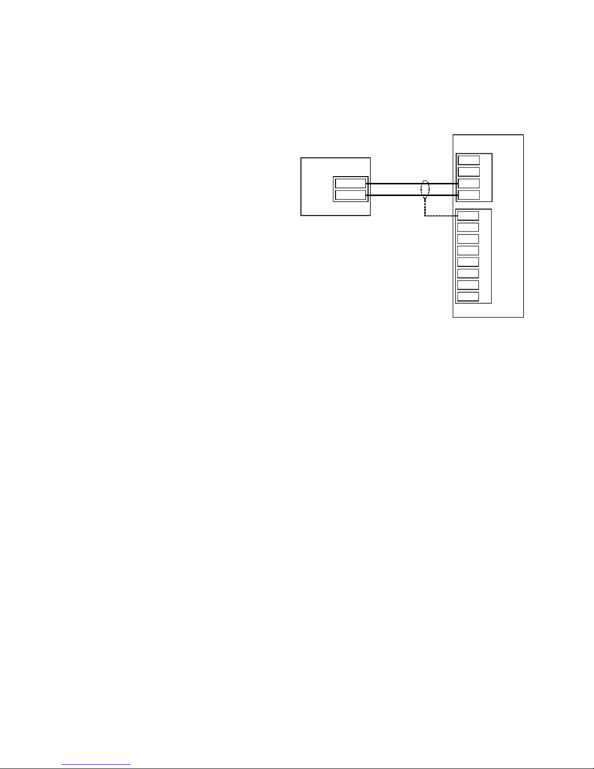
Note: For information on connections at the computer’s serial port, refer to the manual
supplied with the computer. There is not one standard pinout for RS-422/485 connections.
See Appendix A for wiring diagrams for 3 wire and 5 wire RS-422/485 systems.
Digital Communication
A LevelCom 101 may be used as a
remote readout for the LevelCom 100.
This function will use the Digital
Communication option. This requires the
Digital Communication option board to be
installed. This board is installed in the
place of the analog output module on the
Sensor Input Circuit Board. The Digital
Communication module uses the same
output connector as the Analog Output
Module.
LevelCom 100
AOUT -
AOUT +
SHIELD
LevelCom 101
PROC. IN PUT
A
B
C
D
GND
EXTERNAL BUTTONS
ACK
GND
H.S.
GND
B 3
GND
B 4
Important note: The jumpers on the
Sensor Input Circuit Board must be set for
External. Refer to Figure 15 and Figure
Figure 17 Digital Communication Wiring
16 for the correct jumper settings
depending on the version of the Sensor Input Circuit Board.
Figure 17 shows the wiring for this option. Up to 4 LevelCom 101s may be used as remote
readouts; they are daisy chained from the first LevelCom 101 shown in this wiring diagram.
Cable specified for RS-485 communication should be used for these connections.
©2013 Technical Marine Service, Inc. LC-100 V2.97
Page 31
Page 32
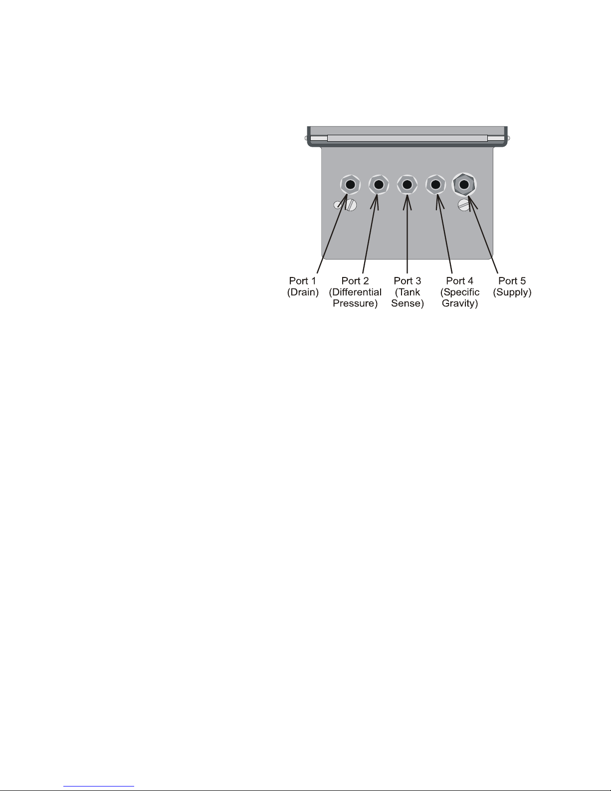
Pneumatic Connections
General
Pneumatic connections are made at
the bottom of the LevelCom 100
enclosure. The instrument is
supplied with fittings installed as
required by the options ordered.
Connections are 1/8” female NPT. If
it is necessary to install a fitting,
thread lubricant should be used
sparingly, with great care taken to
keep excess from entering the
manifold. Do not use PTFE tape on
any pneumatic connections to the
LevelCom 100. Fittings should be
made up only as tight as necessary
to be leak-free. The manifold is
aluminum, and can be distorted by using excessive installation force. Small fittings, such as
1/8” NPT do not require much torque to seal well. The pneumatic connection ports are
discussed below.
In the majority of cases, tubing connections are made only to Port 3, (Tank Sense) and Port
5, (Supply air). See Figure 18. These will usually be the only fittings present. The others
are only present if the relevant options were ordered.
Note: There is a filter between the compression fitting and the manifold body on the Port 5
the air supply fitting. This filter should not be removed from the manifold body. If different
fittings are required proper fittings should be obtained that will thread onto this filter.
Port 1 DRAIN is used at regular intervals by the LevelCom 100 to purge its manifold of any
water, oil or impurities, and to relieve all pressure to the internal sensor for periodic automatic
zero calibration. If desired, the DRAIN connection may be plumbed to a different location, so
that when the LevelCom 100 vents, the air will be directed elsewhere. Tubing is to be made
up tight and leak free and tubing connections must not obstruct flow or contain any valves.
Important Note: Tubing must be arranged so that the entire run slopes downward to the
open end. If liquid can be trapped in this tubing anywhere the hardware zero operation will
not work correctly and the machine accuracy will be affected. Use of clear plastic tubing is
recommended to aid in seeing possible problems with contaminated air.
Figure 18 Pneumatic Connections
©2013 Technical Marine Service, Inc. LC-100 V2.97
Page 32
Page 33
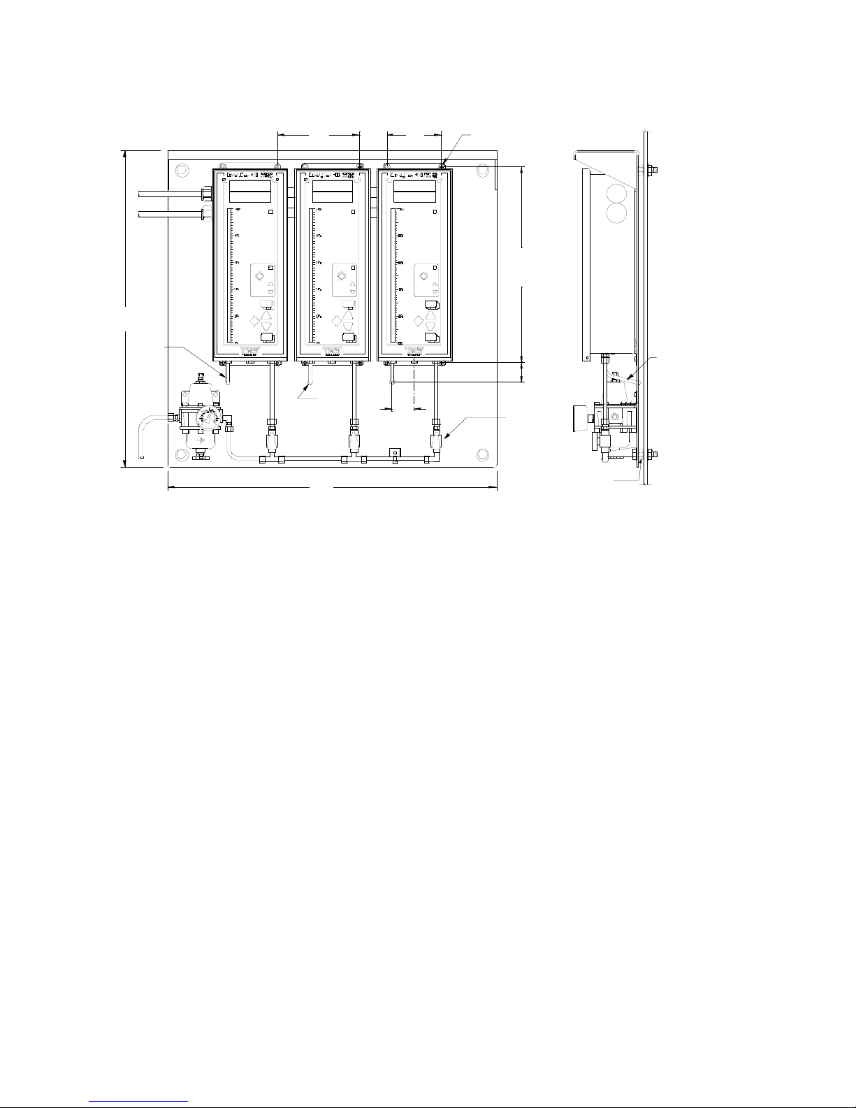
"
4
2
DRAIN
TUBE
"
6
TA N K N o .1
HIGH ALARM
LOW ALARM
M
TROUBLE
D
E
O
UL L A G E
ACK
E
AT
RN
E
A
LT
NI
TS
U
UP
N
D
OW
HO
W
S
NI
TS
U
TANK No .2 TANK N o.3
ULLAGE
TROUBLE
ACK
HIGH ALARM
LOW ALARM
E
AT
R
N
TE
A
L
S
IT
U
N
UP
DE
O
M
N
W
D
O
W
O
S
H
S
IT
U
N
11/32"
HOL E
"
4
2
Figure 19 Pneumatic Tubing Example
"
4
UL L AG E
TR OU BL E
ACK
HI GH A LA RM
LOW A LAR M
E
T
RN
A
E
LT
A
TS
NI
U
UP
D
E
M
O
N
O
W
D
W
HO
S
TS
NI
U
"
.
6
1
#10 SCREW S
"
5
7
.
4
1
"
2
/
1
1
PLU G VAL VE
DRAI N
TUBE
SPACER
Important Note: Each LevelCom 100 must be fitted with a separate drain tube. Drain tubes
from multiple machines must not be connected together. The LevelCom 100 uses the drain
output to read ambient air pressure during a Hardware Zero operation. If drains are tied
together one machine may be purging to the drain while another machine is doing it’s
hardware zero operation, resulting in large errors, or Can’t Zero Sensor fault conditions.
Port 2 D.P. (Differential Pressure) is used when the Tank Pressure Compensation option has
been specified. It connects to the top of the tank in cases where the tank internal pressure is
different from ambient pressure at the LevelCom location. Tubing is to be made up tight and
leak free.
Port 3 TANK SENSE connects to the bubbler pipe in the tank. Tubing is to be made up tight
and leak free.
Port 4 S. G. (Specific Gravity) is used when the Automatic Specific Gravity option has been
specified. It connects to a second bubbler pipe in the tank, and is used only in applications
involving the optional automatic Specific Gravity calculating function. Tubing is to be made
up tight and leak free.
Port 5 SUPPLY should be connected to a clean, dry, source of control air, with the supply
pressure set depending upon the specified range of the LevelCom 100 (see the
specifications on page 2). Tubing is to be made up tight and leak-free. The LevelCom 100’s
©2013 Technical Marine Service, Inc. LC-100 V2.97
Page 33
Page 34

design gives it far less susceptibility to contaminated air than pneumatic devices with small
orifices but a good filter of 40 microns or less is essential to long-term dependable operation.
The importance of good air quality cannot be overemphasized. Contaminated or wet
air can be a source of problems including instrument failure. Be sure that your air
supply and associated tubing is in keeping with good pneumatic instrument
requirements. In installations where more than one LevelCom is connected to the
same air supply, isolation valves for each instrument are recommended.
©2013 Technical Marine Service, Inc. LC-100 V2.97
Page 34
Page 35

Basic Programming
100 Liquid Level Computer is shipped with a default configuration loaded into permanent
memory. For efficient use of the instrument this configuration must be changed to reflect the
tank being monitored. To place a LevelCom 100 in service only those features which are
going to be used need be set up.
The minimum requirements for accurate operation in a fresh water tank are Depth Units,
Maximum Depth and Bubbler to Bottom. Fluids other than fresh water also require the
Specific Gravity of the fluid to be entered. If the tank is used for storage of more than one
type of liquid, TMS recommends the Automatic Specific Gravity option be considered.
To avoid confusion and unnecessary programming steps the LevelCom 100 has been
designed to confine the program display to only those parameters which have been activated
and the options which have been installed. This means that during the programming process
you may notice areas in the Configuration Flow Chart (In the back of this manual) that are not
displayed in the program. For example, if the optional relay outputs are not installed, then
the LevelCom 100 will not display RELAY 1 or RELAY 2. In these instances, the instrument
will skip to the next programming step.
The Configuration Flow Chart reflects all of the parameters and options available with the
LevelCom 100. If you wish to access a parameter or option, which is not presently available
to you, please call TMS for assistance.
Turn to page 65 and read the explanation of how to gather the information you will need for
programming of the LevelCom 100. When the worksheet on page 70 has been completed,
proceed with programming the instrument.
Important Note about Programming
The LevelCom 100 is designed to be “User Friendly”. We encourage you to enter into the
program, browse through the configuration “tree” and become familiar with data entry, the
program flow and the general operation of the unit.
Do not be concerned about changing any values while learning. After exploring the
LevelCom 100 configuration interface all feature selections and parameters you have entered
can be easily erased and the unit returned to the factory set default settings. To reset the
LevelCom 100 to the default condition please follow the steps found on page 36 in Erase All
Memory/Reset Factory Defaults. If at any time you encounter difficulties in programming,
please contact TMS for assistance.
Basic Programming Key Functions
ESCAPE: Allows a user to back out of a menu item without changing settings.
©2013 Technical Marine Service, Inc. LC-100 V2.97
Page 35
Page 36
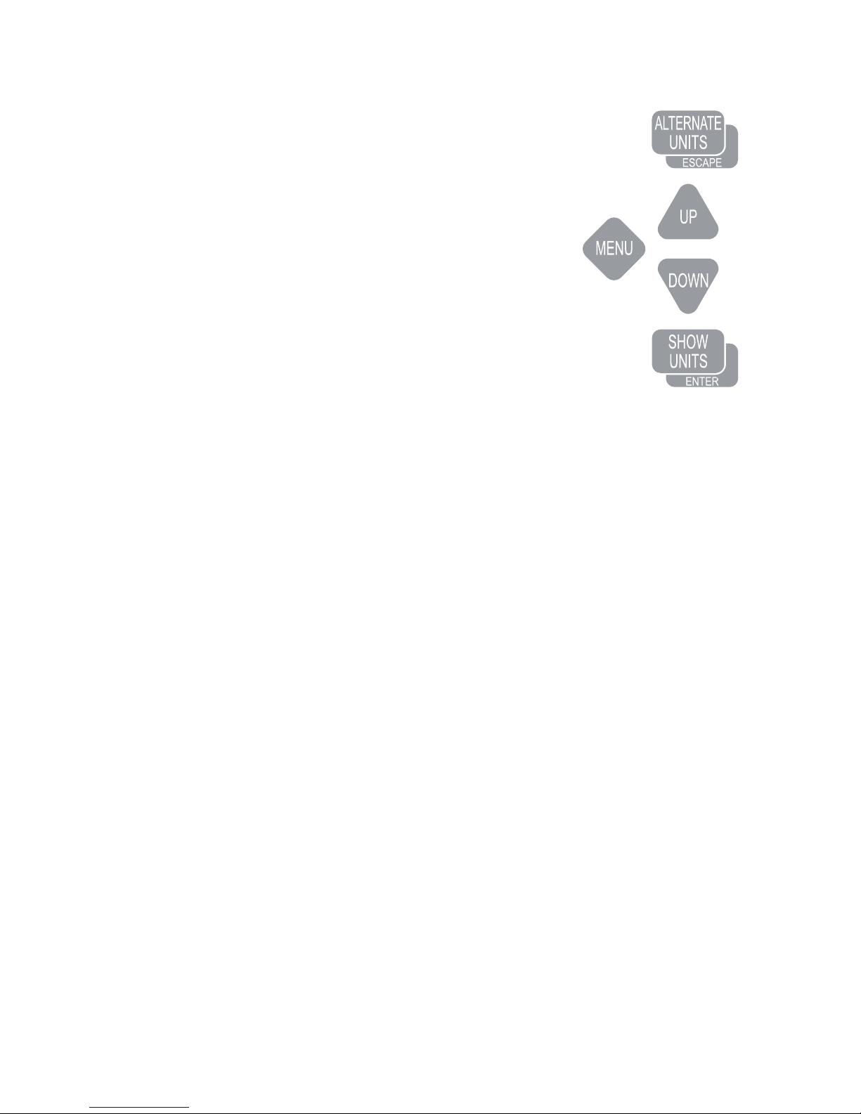
MENU: Places the unit into Program Mode. Also
selects/deselects functions.
UP/DOWN: Scroll vertically through the menu. They are
also used to adjust parameter values.
ENTER: Used to enter the next program level, save
selections and parameter values.
Note: Prior to programming it is recommended that the
operator complete the Programming Worksheet found on
page 70.
The Programming Worksheet contains all user selectable
settings and follows the sequence used in programming the
LevelCom. Use of the Programming Worksheet will ensure
Figure 20 Buttons
that you will have at your fingertips all of the data required
for complete programming of the LevelCom 100. Save the
worksheet for your files.
Entering the program mode
Open the front cover and power up the LevelCom 100 using the power on/off switch. The
unit will initialize and display a numerical value. Close the cover.
Press MENU. The unit will display SYSTEM. You are now in the LevelCom configuration
interface.
Note: If the unit displays ENTER PASSWORD or HOT MENU then the LevelCom 100 has
been previously programmed. Confer with the responsible party prior to proceeding. Note
that one of the benefits of the LevelCom 100 is this very ability to modify the configuration at
will.
If the unit displays HOT MENU please refer to Page 48. If the unit displays ENTER
PASSWORD and the password is not available, please call TMS for assistance.
Erase All Memory Reset Factory Defaults
Note: This section will remove all selections and parameters from memory and the unit will
reset to factory defaults. Use this section only if you have previously entered the program
and made selections and adjustments you want to delete.
At SYSTEM press UP, the unit will display UTILITIES
Press ENTER. The unit will display COMM SETUP.
©2013 Technical Marine Service, Inc. LC-100 V2.97
Page 36
Page 37

Press UP. The unit will display MEMORY.
Press ENTER. The unit will display WRITE OVER BACKUP.
Press UP. The unit will display ERASE ALL MEMORY.
Press ENTER. The unit will display SURE?
Press ENTER. The unit will reset and display SYSTEM.
At SYSTEM continue with programming or press ESCAPE to return to operation with factory
set defaults.
Display Setup
Note: All descriptions of configuring the display assume that the LevelCom 100 is
being configured for the first time after the memory has been erased. If the unit
already has an existing configuration the initial numbers seen when entering the
Maximum Depth and the Bubbler to Bottom values will be different than described in
this procedure.
1. At SYSTEM press ENTER. The unit will display DISPLAY SETUP
2. Press ENTER. The unit will display DEPTH UNITS.
3. Press ENTER. The unit will display INCHES*.
4. Press UP or DOWN to scroll to the depth unit of measure you have chosen for use.
5. Press MENU to select the choice. An asterisk (*) will appear to the right of the display
indicating the item has been selected. If depth is to be displayed in ullage proceed to the
next step, if not then proceed to step 7.
6. Press UP or DOWN to scroll to ULLAGE. Press MENU if you wish depth to be displayed
in ullage. An asterisk (*) will appear to the right of the display indicating the item has
been selected.
7. Press ENTER to save the selection(s). SAVING will appear briefly on the display and the
display will return to DEPTH UNITS indicating the selection has been recorded.
8. Press DOWN. The unit will display VOLUME UNITS.
9. Press ENTER. The unit will display NOT USED*.
10. Press UP or DOWN to scroll to the volume unit of measure you have chosen for use.
©2013 Technical Marine Service, Inc. LC-100 V2.97
Page 37
Page 38

11. Press MENU to select the choice. An asterisk (*) will appear to the right of the display
indicating the item has been selected. If volume is to be displayed in ullage proceed to
the next step, if not then proceed to step 13.
12. Press UP or DOWN to scroll to ULLAGE. Press MENU if you wish volume displayed in
ullage.
13. Press ENTER to save the selection(s). SAVING will appear briefly on the display and the
display will return to VOLUME UNITS indicating the selection has been recorded.
14. Press DOWN. The unit will display WEIGHT UNITS.
15. At WEIGHT UNITS press ENTER. The unit will display NOT USED*.
16. Press UP or DOWN to scroll to the weight unit of measure you have chosen for use.
17. Press MENU to select the choice. An asterisk (*) will appear to the right of the display
indicating the item has been selected. If weight is to be displayed in ullage proceed to the
next step, if not then proceed to step 19.
18. Press UP or DOWN to scroll to ULLAGE. Press MENU if you wish weight displayed in
ullage.
19. Press ENTER to save the selection. SAVING will appear briefly on the display and the
display will return to WEIGHT UNITS indicating the selection has been recorded.
20. Press DOWN. The unit will display DISPLAY UNITS.
Note: DISPLAY UNITS will appear only if either Volume or Weight units were selected. In
the case of depth only being selected the unit will display TANK TABLE.
21. At DISPLAY UNITS press UP or DOWN to scroll to the unit of measure you have chosen for
normal display.
Note: The choice of Display Units will determine the unit of measure the LevelCom 100 will
use to set Alarm Setpoints later in the programming procedure. It may simplify programming
to set the Display Unit as depth until programming has been completed. After the program
has been entered you can return to this point in the program and change the display as
desired.
22. Press MENU to select the choice. An asterisk (*) will appear to the right of the display
indicating the item has been selected.
23. Press ENTER to save the selection. SAVING will appear briefly on the display and the
display will return to DISPLAY UNITS indicating the selection has been recorded.
24. Press DOWN. The unit will display TANK TABLE.
©2013 Technical Marine Service, Inc. LC-100 V2.97
Page 38
Page 39

25. Press ENTER. The unit will display MAX DEPTH.
26. Press ENTER. The unit will display the factory default Max Depth (i.e. if feet/ inches were
selected as the Depth Unit the LevelCom will display 31’ 0.0”, 62’ 0.0” or 90’ 0.0”
depending on the installed sensor).
27. Press UP or DOWN to scroll to the maximum vertical dimension of the tank in the Depth
Unit of measure you chose in step #5 above.
28. Press ENTER to save the dimension. SAVING will appear briefly on the display and the
display will shift to MAX VOLUME or MAX WEIGHT indicating the dimension has been
recorded.
Note: The configuration of the Tank Table is determined by the selection of Weight, Volume,
and Display Units. If neither Volume nor Weight was selected then the unit will not display
TANK TABLE and will instead display BUBBLER TO BOTTOM. If this is the case please
proceed to step 32.
29. At MAX VOLUME/WEIGHT press ENTER. The unit will display 0.
30. Press UP or DOWN to scroll to the maximum volume/weight of the tank in the units of
measure selected above.
31. Press ENTER to save the parameter. SAVING will ap pear briefly on the display and the
display will shift to D9 indicating the selection has been recorded.
Note: D9 will not appear if a Maximum Volume/Weight is not entered. In this case the unit
will display BUBBLER TO BOTTOM.
Note: A Tank Table is required to configure the LevelCom 100 to an irregular shaped tank. If
this feature is required please refer to page 48, Advanced Programming for instructions.
32. At BUBBLER TO BOTTOM press ENTER. The unit will display 0.0.
33. Press UP or DOWN to scroll to the bubbler to bottom distance using the Depth Units you
selected in step #5 above.
34. Press ENTER to save. SAVING will appear briefly on the display and the display will shift
to MAX DEPTH.
Note: If you have installed the Automatic Specific Gravity option then the display will shift to
S G DISTANCE.
35. At S G DISTANCE press ENTER. Unit will display 0.0.
©2013 Technical Marine Service, Inc. LC-100 V2.97
Page 39
Page 40

36. Press UP or DOWN to scroll to the specific gravity distance using the Depth Units you
selected in step #5 above.
37. Press ENTER to save. SAVING will appear briefly on the display and the display will shift
to MAX DEPTH.
38. Press ESCAPE. Unit will display DISPLAY SETUP.
39. Proceed with the next programming step or press ESCAPE twice to return to normal
operation.
Sample and Purge Timing
The Timing program establishes three parameters. Sample and Purge regulate the
frequency of level samples and purge functions. Purge Duration allows the operator to set
the amount of time (from 5 to 180 seconds) required for a complete purge of the sense line
system.
1. At DISPLAY SETUP press DOWN. Unit will display TIMING.
2. Press ENTER. Unit will display SAMPLE.
3. Press ENTER. Unit will display AUTO.
Note: Selecting Auto will force the LevelCom 100 to automatically take a sample whenever a change in level is detected. Auto and a
predetermined sample interval can be selected at the same time. If the tank being monitored
is subject to rolling, Auto will force the LevelCom 100 to chase the level in the tank as the
vessel rolls. Consider alarm/control issues when selecting the Auto feature.
4. Press UP or DOWN to scroll to the sample cycle time you have chosen for use.
5. Press MENU to select the choice. An asterisk (*) will appear to the right of the display
indicating the item has been selected.
6. Press ENTER to save the selection. SAVING will appear briefly on the display and the
display will shift to SAMPLE.
7. Press DOWN. Unit will display PURGE.
8. Press ENTER. Unit will display 1 HR.
9. Press UP or DOWN to scroll to the purge cycle time you have chosen for use.
10. Press MENU to select the choice. An asterisk (*) will appear to the right of the display
indicating the item has been selected.
©2013 Technical Marine Service, Inc. LC-100 V2.97
Page 40
Page 41

11. Press ENTER to save the selection. SAVING will appear briefly on the display and the
display will shift to PURGE.
12. Press DOWN. Unit will display PURGE DURATION.
13. Press ENTER. Unit will display 5 seconds.
14. Press UP or DOWN to set the purge duration (from 5-180 seconds) you need.
15. Press ENTER to save the selection. SAVING will appear briefly on the display and the
display will shift to PURGE DURATION.
16. Press ESCAPE. Unit will display TIMING.
17. Proceed with the next programming step or press ESCAPE twice to return to normal
operation.
Specific Gravity Setup
If Automatic Specific Gravity Option is not installed use this procedure.
1. At TIMING press DOWN. Unit will display SPEC GRAV.
2. Press ENTER. Unit will display 1.000.
3. Press UP or DOWN to scroll to the specific gravity of the liquid stored in the tank.
4. Press ENTER to save the selection. SAVING will appear briefly on the display and the
display will shift to SPEC GRAV.
5. Proceed with the next programming step or press ESCAPE twice to return to normal
operation.
If Automatic Specific Gravity Option is installed there are more items to set up. Use the
following procedure to set up for automatic specific gravity operation.
Note: If the Automatic Specific Gravity option is installed the SG DISTANCE parameter must
be setup under DISPLAY SETUP (page37). If this parameter is not set up correctly
Automatic Specific Gravity will not function.
You can run the LevelCom 100 in either manual or automatic specific gravity. You should set
up a manual specific gravity value even if you intend to operate the machine in automatic.
On power up the manual value of specific gravity is used initially before the first good specific
gravity value is read. Also if there is a problem detected on the specific gravity sense line the
©2013 Technical Marine Service, Inc. LC-100 V2.97
Page 41
Page 42

LevelCom 100 will revert to manual specific gravity operation. In this case the manual
specific gravity value is used.
To set the manual specific gravity value use the following procedure.
1. At TIMING press DOWN. Unit will display SPEC GRAV.
2. Press ENTER. Unit will display AUTO.
3. Press DOWN. Unit will display MANUAL.
4. Press MENU. An asterisk (*) will appear to the right of the display indicating the item has
been selected.
5. Press ENTER. Unit will display the current manual specific gravity value, 1.000 is the
default value.
6. Press UP or DOWN to scroll to the specific gravity of the liquid most likely to be stored in
the tank.
7. Press ENTER to save the value. SAVING will appear briefly on the display and the
display will shift to MANUAL.
8. Proceed with the next programming step or press ESCAPE three times to return to
normal operation.
With the manual specific gravity value set up use the following procedure to put the
LevelCom 100 into the Automatic Specific Gravity mode.
1. At TIMING press DOWN. Unit will display SPEC GRAV.
2. Press ENTER. Unit will display AUTO.
3. Press MENU. An asterisk (*) will appear to the right of the display indicating the item has
been selected.
4. Press ENTER. Unit will display the current specific gravity value. The LevelCom 100 is
now operating in Automatic Specific Gravity mode, however if you just selected this mode
in this step the value displayed will initially be the manual specific gravity value. The
LevelCom 100 will have to go through at least one sample operation to update the
specific gravity value.
5. press ESCAPE three times to return to normal operation.
Note: There is a digital filter that can be set up to reduce noise in the specific gravity
reading. Using this filter will slow the LevelCom 100’s reaction to changes in the actual
©2013 Technical Marine Service, Inc. LC-100 V2.97
Page 42
Page 43

specific gravity value though so you should only use the filter value needed. The filter is a
simple digital filter that works in the following way. The current specific gravity value is
multiplied by the filter value, then the new specific gravity reading is added to this, finally the
result is divided by the filter value plus one. As an equation it looks s like this:
((SGo * Filter) + SGn)/(Filter +1)
SGo is the current value of specific gravity
SGn is the new specific gravity reading
Filter is the filter value
A filter value of 0 disables the filter.
To configure the specific gravity filter value use the following procedure.
1. At TIMING press DOWN. Unit will display SPEC GRAV.
2. Press ENTER. Unit will display AUTO.
3. Press DOWN until unit displays FILTER SETUP.
4. Press ENTER. Unit will display the current filter value, the default is 0.
5. Press UP or DOWN to scroll to the desired filter value.
6. Press ENTER to save the value. SAVING will appear briefly on the display and the
display will shift to DISPLAY SETUP.
7. Press ESCAPE three times to return to normal operation.
Configuring Output Lights
This setup assumes that there are no optional outputs installed in the LevelCom 100. See
the Advanced Programming section for configuring the optional outputs. This section only
describes the alarm lights on the LevelCom 100 front panel.
1. At SYSTEM press DOWN. Unit will display OUTPUTS.
2. Press ENTER. Unit will display LIGHTS.
3. Press ENTER. Unit will display HI HI.
4. Press UP or DOWN to scroll to the ALARM points yo u wish to be indicated on the front
panel alarm indicator lamps. Press MENU to select choices. An asterisk (*) will appear
to the right of the display indicating the alarm points that have been activated.
©2013 Technical Marine Service, Inc. LC-100 V2.97
Page 43
Page 44

Note: Selection of Latch will disable the automatic clearing of alarms until the user has
pressed ACK.
5. Press ENTER to save selections. SAVING will appear briefly on the display and the
display will shift to LIGHTS.
Note: Horn and relay outputs are optional. If these options are installed please refer to page
52 for instructions.
Setting Alarm Setpoints
Note: Alarm setpoints are adjusted using the Display Units previously selected. For
example, if the LevelCom 100 is programmed for depth and weight (e.g. feet/inches and long
tons), and is displaying weight, then the alarm setpoints will appear in long tons. At any time
you may enter the program and change depth, volume, weight and display units. The
LevelCom 100 will automatically convert to the new parameters.
6. At LIGHTS press DOWN until unit displays ALARM SETPOINTS.
7. Press ENTER. Unit will display only those alarm points, which were selected as alarm
outputs in Lights, Horn or Relays 1 and 2.
8. At the displayed alarm (i.e. HI HI) press ENTER. Unit will display the depth distance (or
calculated volume/weight at the Bubbler to Bottom distance) specified in Bubbler to
Bottom.
9. Press UP or DOWN to scroll to the alarm setpoint using the units of measure selected in
Display Units.
10. Press ENTER to save the selection. SAVING will appear briefly on the display and the
display will shift to HI HI HYST.
11. Press ENTER. Unit will display 0 . 0.
12. Press UP or DOWN to set the hysteresis. Scroll to the distance from the alarm setpoint
you choose to have the alarm condition clear automatically.
13. Press ENTER to save the selection. SAVING will appear briefly on the display and the
display will shift to the next alarm set point.
Alarm Timeout
An optional alarm timeout may be configured on the LevelCom 100. This can be used to
prevent nuisance alarms when the liquid level is near an alarm setpoint. The alarm condition
must be present for longer than the configured timeout time before an alarm is triggered.
The maximum timeout value is 30 seconds.
©2013 Technical Marine Service, Inc. LC-100 V2.97
Page 44
Page 45

1. At LIGHTS press DOWN until unit displays ALARM SETPOINTS.
2. Press ENTER. Unit will display only those alarm points, which were selected as alarm
outputs in Lights, Horn or Relays 1 and 2.
3. Press UP or DOWN until unit displays TIMEOUT TIME.
4. Press ENTER. Unit will display the current timeout value, 0 is the default.
5. Press UP or DOWN to scroll to the desired alarm timeout value.
6. Press ENTER to save the selection. SAVING will appear briefly on the display and the
display will shift to TIMEOUT TIME.
7. Press ESCAPE three times to return to normal operation.
Serial Port Setup and Diagnostics
The serial port of the communication interface may be configured for different baud rates and
parity settings. These are mostly used for machines configured for Modbus communications.
The default baud rate is 9600 baud, the default parity setting is N-8-1. These may be
changed as needed.
When a group of LevelCom 100s are networked together using a Modbus network, each
machine must have a distinct network address. Network communications will not work if two
or more machines have the same network address.
1. At SYSTEM press UP, the unit will display UTILITIES.
2. Press ENTER. The unit will display COMM SETUP.
3. Press ENTER. The unit will display NETWORK ADDRESS.
4. Press ENTER.
5. Press UP or DOWN to scroll to the required network address.
6. Press ENTER to save the selection. SAVING will appear briefly on the display. The
display will return to NETWORK ADDRESS.
The baud rate must agree with the setting in the computer that the LevelCom 100s are
connected to. The most common setting is 9600 baud. To set the baud rate use the
following procedure.
1. At SYSTEM press UP, the unit will display UTILITIES.
©2013 Technical Marine Service, Inc. LC-100 V2.97
Page 45
Page 46

2. Press ENTER. The unit will display COMM SETUP.
3. Press ENTER. The unit will display NETWORK ADDRESS.
4. Press DOWN. The unit will display BAUD RATE.
5. Press ENTER. This unit will display 1200.
6. Press UP or DOWN to scroll to the required baud rate. The possibilities are 1200, 2400,
4800, 9600, and 19200.
7. With the desired baud rate showing on the display, press MENU to select. An asterisk
will show on the right side of the character display
8. Press ENTER to save the selection. SAVING will appear briefly on the display. The
display will return to BAUD RATE.
You also need to verify the parity setting of the device you are connecting the LevelCom 100
to. The most common setting is N-8-1, no parity, 8 bits per byte, one stop bit. This will be
the normal default for interfacing to desktop computers.
The other settings are often encountered when interfacing to PLCs or data scanners. Some
of these devices will not support N-8-1 parity settings. If no parity is used they may operate
with the parity bit always set, this will be N-8-2 parity. Alternately they may only support even
or odd parity settings. To determine the required setting see the manual for the device you
are connecting the LevelCom 100 to.
1. At SYSTEM press UP, the unit will display UTILITIES.
2. Press ENTER. The unit will display COMM SETUP.
3. Press ENTER. The unit will display NETWORK ADDRESS.
4. Press DOWN twice. The unit will display PARITY.
5. Press ENTER. The unit will display N-8-1.
6. Press UP or DOWN to scroll to the required parity. The possibilities are N-8-1, N-8-2,
EVEN (E-8-1), and ODD (O-8-1).
7. With the desired parity setting showing on the display, press MENU to select. An asterisk
will show on the right side of the character display
8. Press ENTER to save the selection. SAVING will appear briefly on the display. The
display will return to PARITY.
©2013 Technical Marine Service, Inc. LC-100 V2.97
Page 46
Page 47

The LevelCom 100 must be configured to use the Modbus protocol. It may also alternately
be configured to use a TMS proprietary protocol using checksums for error detection or not.
1. At SYSTEM press UP, the unit will display UTILITIES.
2. Press ENTER. The unit will display COMM SETUP.
3. Press ENTER. The unit will display NETWORK ADDRESS.
4. Press DOWN three times. The unit will display PROTOCOL.
5. Press ENTER. The unit will display NO CHK.
6. Press UP or DOWN to scroll to the required protocol. The possibilities are NO CHK for
TMS protocol without checksums for error detection, CHK for TMS protocol with
checksums for error detection, and MODBUS for Modbus RTU protocol.
7. With the desired protocol setting showing on the display, press MENU to select. An
asterisk will show on the right side of the character display
8. Press ENTER to save the selection. SAVING will appear briefly on the display. The
display will return to PROTOCOL.
©2013 Technical Marine Service, Inc. LC-100 V2.97
Page 47
Page 48

Advanced Programming
This section addresses the programming of the more advanced features of the LevelCom
100. These features include setting up a Tank Table, establishing password protection of the
LevelCom 100 configuration, setting up a Hot Menu, and the setup of optional outputs.
This section assumes the LevelCom 100 has been programmed for basic use. If the unit has
not been programmed please refer to page 35, Basic Programming.
Use caution as you move through the program. If you inadvertently access a section of the
program containing data you do not wish to adjust, simply press ESC to back out to the
previous program point. Following the Configuration Flow Chart as you move through the
program will assist you.
Entering the Program Mode
From normal operation press MENU. The Program Mode indicator lamp will light. The unit
will display SYSTEM.
Note: If the unit displays ENTER PASSW ORD or HOT MENU then the LevelCom 100 has
been previously programmed. Confer with the responsible party prior to proceeding. If the
unit displays HOT MENU please refer to the following section. If the unit displays ENTER
PASSWORD and the password is not available please call TMS for assistance.
Entering the Program Mode with A Hot Menu established
The LevelCom 100 program allows the user to establish a Hot Menu, which allows access to
selectable parameters and functions without the need to enter the program. The Hot Menu feature
provides a means to access and adjust commonly used features, e.g., alarm and relay setpoints,
specific gravity, sample timing, etc. without entering into the full program. Items available for the Hot
Menu are indicated on the Configuration Flow Chart. For instructions on programming a Hot Menu
please turn to page 52.
Once programmed, the Hot Menu is instantly accessible from normal operation simply by pressing the
MENU key.
If a Hot Menu is set up, then entering the Program Mode requires some additional steps.
1. From normal operation press MENU. Program Mode indicator lamp will light. The un it
will briefly display HOT MENU and the display will shift to the first Hot Menu selection.
2. Press the UP key. The unit will display CONFIGURE SYSTEM.
3. Press ENTER. If no password is required, the unit will display SYSTEM. For information
on passwords please see Page 51.
©2013 Technical Marine Service, Inc. LC-100 V2.97
Page 48
Page 49
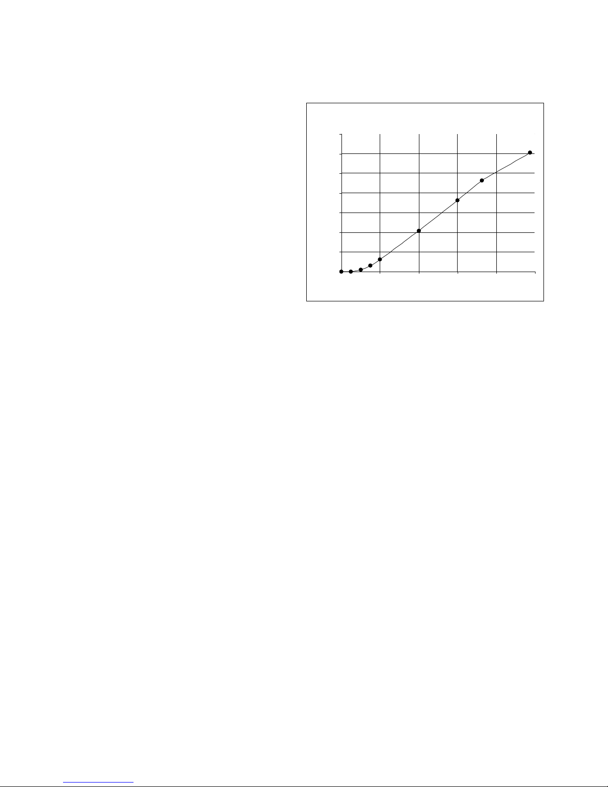
Tank Table Explained
Accurate depth to volume/weight data is
required to calculate the volume and weight
of the tank’s contents. In regularly shaped
tanks, (regular in this case refers to a tank
3500
3000
Tank Capacity Curve
with a linear depth to volume/weight curve),
the LevelCom 100 requires only Maximum
Depth, Maximum Volume/Weight and
2500
2000
Bubbler to Bottom be entered in order to
calculate the volume and weight at any
depth.
If the tank has an irregular shape, e.g.,
spherical, slanted or curved sides, a
hopper bottom, etc., then a Tank Table
must be established to ensure accurate
volume/weight calculations. The LevelCom
100 Tank Table allows the user to establish
ten (10) vertical levels within the tank that
define the shape. The top level is
Maximum Depth and Maximum
Volume/Weight, which defines the total
depth and volume/weight when the tank is
full.
The LevelCom 100 program interpolates
linearly between the Tank Table points.
Accordingly, as a general rule of thumb, the
Tank Table should be established by
placing the points of the Tank Table in the
areas with the greatest change. For
1500
Volume in Gallons
1000
500
0
0246810
Depth in Feet
depth
ft.
MAX
D 9.75
volume
gal
MAX V
3023
D9 7.25 V9 2321
D8 6 V8 1816
D7 4 V7 1042
D6 2 V6 310
D5 1.5 V5 151
D4 1 V4 44
D3 0.5 V3 4
D2 0 V2 0
Figure 21 Tank Table Example
example, if the tank is a hopper, then the
Tank Table should be concentrated at the
bottom. If the tank requires a higher degree of accuracy at the top and bottom, as in a day
tank, then concentrate the points at the top and bottom to ensure high accuracy in those
areas.
The best source for the tank data can usually be found in the Tank Capacity Curve drawings.
While sometimes useful, we recommend you use caution if you are deriving the data from
the tank Sounding Tables. Consider the issues of the sounding tube length, the termination
point of the tube and curves in the sounding tubes. The LevelCom 100 works off of the
pressure exerted by the weight of the column of liquid over the end of the bubbler pipe.
Using sounding tube data can be misleading, the most common issue being the added length
due to curves inside the tank and the tube terminating outside the tank.
©2013 Technical Marine Service, Inc. LC-100 V2.97
Page 49
Page 50

The Tank Table can consist of from one to 10 level entries. Use as many levels as required
to achieve the best accuracy. Levels must be entered from the top of the tank working
down. TMS recommends the user plot a chart, which graphs the depth to volume/weight
curve. This provides the best means to determine the points of greatest depth to
volume/weight change and the optimum arrangement for the Tank Table (Figure 21).
Transfer this data to the Programming Worksheet for the tank and proceed with the
programming instructions below. If you require assistance in establishing the Tank Table
please call TMS.
Programming a Tank Table
1. Enter Program Mode by pressing the MENU key.
2. At SYSTEM press ENTER. The unit will display DISPLAY SETUP.
3. Press ENTER. The unit will display DEPTH UNITS.
4. Press UP. The unit will display TANK TABLE.
5. Press ENTER. The unit will display MAX DEPTH.
6. Press ENTER. The unit will display the parameter that was assigned during Basic
Programming. Confirm that this value is correct and modify if required.
7. Press ENTER. The unit will display MAX VOLUME or MAX WEIGHT.
8. Press ENTER. The unit will display either 0 or the parameter that was assigned during
Basic Programming.
9. If 0 press UP or DOWN to scroll to the maximum capacity of the tank. If a parameter has
already been established, confirm that the value is correct and proceed to the following
step.
10. Press ENTER to save the selection. If a new value was assigned SAVING will appear
briefly on the display and the display will shift to D9.
11. Press ENTER. The unit will display 0.0.
12. Press UP or DOWN to scroll to the depth at point D9 using the Depth Units selected in
Basic Programming.
13. Press ENTER to save the selection. SAVING will appear briefly on the display and the
display will shift to V9 or W9.
14. Press ENTER. The unit will display 0.0.
©2013 Technical Marine Service, Inc. LC-100 V2.97
Page 50
Page 51

15. Press UP or DOWN to scroll to the total tank volume at point #9 using the Volume or
Weight Units selected in Basic Programming.
16. Press ENTER. SAVING will appear briefly on the display and the display will shift to D8.
17. Repeat steps 11 through 16 for Depth and Volume/Weight levels 8 through 1. After all
levels are programmed, the unit will display BUBBLER TO BOTTOM.
18. At BUBBLER TO BOTTOM press ESCAPE to return to normal operation or press ENTER
to program the Bubbler to Bottom if not done already.
Password
Access to the LevelCom 100 program can be restricted by the use of a password. As
previously discussed, the LevelCom 100 can be programmed with a user defined Hot Menu
which will provide immediate, non-password-protected access to some commonly used
features.
If a password has been set up the LevelCom 100 will display ENTER PASSWORD whenever
an attempt is made to enter into the program mode. Once the password has been
programmed and the program exited, the password must be used. The password is entered
using the same keystrokes as described below in Programming a Password steps 4 - 8.
Programming a Password
1. Press MENU. The unit will display SYSTEM.
2. Press UP or DOWN to scroll to NEW PASSWORD.
3. Press ENTER. The unit will display a flashing underline as a cursor.
Note: The LevelCom 100 password selection consists of the letters A-Z. A password of 1 to
9 characters can be set up.
4. Press UP or DOWN to scroll to the first character.
5. Simultaneously press MENU and the UP key to shift to the next character.
6. Press UP or DOWN to scroll to the second character.
7. Repeat steps five and six until your password is displayed.
8. Press ENTER. SAVING will appear briefly on the display and the display will return to
NEW PASSWORD indicating your password has been saved.
©2013 Technical Marine Service, Inc. LC-100 V2.97
Page 51
Page 52

Note: This password will be required to enter into the configuration program. TMS
recommends you set up a Hot Menu to access those parameters you would like accessible
but not password protected. If the password is lost please call TMS for assistance.
Hot Menu
The LevelCom 100 is programmed with a Hot Menu feature. This allows the user to set up
certain parameters and functions into a menu that is instantly accessible simply by pressing
the MENU key. This feature is especially helpful if the user has set up password protection.
Once the Hot Menu has been programmed the LevelCom 100 will display HOT MENU when
the MENU key is pressed. The parameters set up in the Hot Menu are accessible by
scrolling with the UP or DOWN keys.
Programming Hot Menu
1. Enter Program Mode by pressing the MENU key.
2. At SYSTEM press the UP or DOWN keys to scroll to HOT MENU.
3. Press ENTER. The unit will display the first alarm point activated, HI for example. If no
alarms are configured the display will show SPEC GRAV.
4. Press the UP or DOWN keys to scroll through the functions and parameters available for
the Hot Menu.
5. Select those functions/parameters you wish displayed in the hot menu by pressing the
MENU key. An asterisk (*) will appear to the right of the display indicating the item has
been selected.
6. After selecting the Hot Menu items press ENTER. SAVING will appear briefly on the
display and the display will return to HOT MENU indicating the selections have been
recorded.
7. Press ESCAPE to return to normal operation.
LevelCom Outputs
The LevelCom 100 has a number of output devices available. The alarm and fault lights in
the front panel are always available. In addition there are optional relays that can be
configured to function as alarm, or control outputs, an optional horn to give local alarm
indication, an optional 4-20 mA output that can be used as a gauge, or control output. The
LevelCom 100 can also be equipped with an optional digital communication interface that
allows it to communicate with up to four remotely mounted LevelCom 101 Repeaters.
©2013 Technical Marine Service, Inc. LC-100 V2.97
Page 52
Page 53

The LevelCom 100 automatically detects any installed optional output devices on power up.
The Outputs menu will reflect this. For instance if no relay module is installed in the
LevelCom 100 the Relays menu item will not appear in the Outputs menu. Because of this
the menus on your machine may not exactly match the menus as shown on the programming
interface map at the end of this manual.
To program alarms the alarm points must first be assigned to output devices, lights, relays, or
horn. After assigning alarms to outputs the alarm setpoints and hysteresis values can be set.
For instance if you have assigned high and low alarms to lights, you will be able to set up the
alarm setpoints for these alarms under the Alarm Setpoints menu. You will not be able to set
up a setpoint for the High High alarm, or the Low Low alarm though. These alarms have not
been assigned to outputs.
Lights
The front panel lights provide a way to locally display fault and alarm status information. If
Latch is selected, the alarm lights will remain active until the user presses the ACK key to
acknowledge the alarm condition, even if the alarm condition has cleared. If Latch is not
selected, then the light will activate only during the alarm event and will automatically clear at
the assigned alarm hysteresis.
1. Enter Program Mode by pressing the MENU key.
2. At SYSTEM press the UP or DOWN keys to scroll to OUTPUTS.
3. Press ENTER. The unit will display LIGHTS.
4. Press ENTER. The unit will display HI HI.
5. Select those alarms you wish to activate the lights by pressing the MENU key. An
asterisk (*) will appear to the right of the display indicating the alarm has been selected.
6. Press ENTER to save the selected alarms. SAVING will appear briefly on the display a nd
the display will return to LIGHTS indicating the selections have been recorded.
7. Press ESCAPE to return to normal operation.
Horn Output
The LevelCom 100 has an optional front panel horn output. If you have ordered this feature
then the LevelCom 100 will display HORN under the Outputs section of the program (Please
refer to the Configuration Flow Chart). The Horn function allows the user to select which
alarms will activate a front panel mounted audible signal. If Latch is selected, the alarm will
sound until the user presses the ACK key to acknowledge the alarm condition, even if the
alarm condition has cleared. If Latch is not selected, then the horn will sound only during the
alarm event and will automatically clear at the assigned alarm hysteresis.
©2013 Technical Marine Service, Inc. LC-100 V2.97
Page 53
Page 54

Programming Horn Output
1. Enter Program Mode by pressing the MENU key.
2. At SYSTEM press the UP or DOWN keys to scroll to OUTPUTS.
3. Press ENTER. The unit will display LIGHTS.
4. Press the DOWN key. The unit will display HORN.
5. Press ENTER. The unit will display HI HI.
6. Select those alarms you wish to activate the horn by pressing the MENU key. An asterisk
(*) will appear to the right of the display indicating the alarm has been selected.
7. Press ENTER to save the selected alarms. SAVING will appear briefly on the display a nd
the display will return to HORN indicating the selections have been recorded.
8. Press ESCAPE to return to normal operation.
Relay Outputs
The LevelCom 100 has two optional “Form C” relay outputs. These relay outputs allow the
user to configure the LevelCom 100 to activate external operations, such as, alarms, motor
controls, etc. If you have ordered relay outputs then the LevelCom 100 will display RELAY 1
and RELAY 2 under the Outputs section of the program (Please refer to the Configuration
Flow Chart).
The relays can be programmed to be either alarm or control outputs. If relays are configured
as alarm outputs, they will function similarly to the light or horn outputs. The relays differ
from the lights and the horn in that they do not normally respond to the ACK button. They
normally activate when the alarm condition occurs, and clear at the assigned hysteresis level.
Relays cannot be configured to latch. As alarm outputs the relays are intended for
interfacing the LevelCom 100 to existing alarm systems.
It is possible to configure an alarm relay to be locally acknowledged. In this case the relay
will respond to the ACK button. This setup can be used to build a local alarm system for a
group of LevelCom 100s. The relay outputs from each LevelCom 100 can be paralleled to
run an alarm horn. To silence the horn, the ACK button must be pressed on the LevelCom
100 which is generating the alarm.
When a relay is configured as a System Failure relay, it will respond only to failure
conditions, such as Sense Line Plugged, Sense Line Leak, and so on.
©2013 Technical Marine Service, Inc. LC-100 V2.97
Page 54
Page 55

Programming Relay Outputs
Note: The following procedure applies to both relay outputs. Follow the same procedure for
Relay 2.
Alarm Relay Configuration
Follow these instructions to set up a relay for ALARM or SYS FAIL operation.
1. Enter Program Mode by pressing the MENU key.
2. At SYSTEM press the UP or DOWN keys to scroll to OUTPUTS.
3. Press ENTER. The unit will display LIGHTS.
4. Press the DOWN key until unit displays RELAY 1.
5. Press ENTER. The unit will display ALARM.
6. Press the UP or DOWN keys to scroll to ALARM, or SYS FAIL .
7. Press MENU to select the function of the relay. An asterisk (*) will appear to the right of
the display indicating the function has been selected. Also select LOCAL if you choose to
have the relay acknowledgeable from the LevelCom 100 front panel ACK key.
8. Press ENTER. SAVING will appear briefly on the display. If SYS FAIL was selected
press ESCAPE to back out of the menu. If ALARM was selected please continue below.
9. The unit will display HI HI.
10. Press the UP or DOWN keys to scroll through the menu selections.
11. Press MENU key to select those alarms you wish activated.
12. Press ENTER. SAVING will appear briefly on the display and the display will shift to
ALARM.
13. Press ESCAPE to return to normal operation.
Control Relay Configuration
When a relay is set up as a control relay there are two setpoints that must be defined; the on
setpoint and the off setpoint. The relay will be energized when the level reaches the ON
SETPOINT value and the relay will be de-energized when the level reaches the OFF
SETPOINT value. This is simple enough but there are other factors to consider before
setting the relays up.
©2013 Technical Marine Service, Inc. LC-100 V2.97
Page 55
Page 56

The control option was designed with the intent of controlling a pump or a valve to main tain
the level of a tank. If such control is to be implemented it is important to consider what will
happen in case there is a failure in the system. The LevelCom 100 will de-energize the relay
when any system failure condition is indicated. These include supply air failure, plugged
sense lines, or onboard hardware failures. When any of these conditions occurs, the
LevelCom 100 is no longer able to measure the level in the tank and it enters a fault mode
and the relays are de-energized. This way the relays go to the same state they would go to if
the LevelCom 100 lost power.
It is very important to consider what will happen to the controlled pump or valve in this case.
Should the pump run (fail on) or should it shut down (fail off) in this case? If the pump is
filling the tank it should probably shut off to avoid overflowing the tank. However if the pump
is emptying the tank, and the pump can handle continuous operation it might be better for the
pump to fail running, again to avoid overfilling the tank. Since the LevelCom 100 relays have
form C contacts it is possible to handle all possible combinations.
First it is important to identify the required failure action. This will determine whether to use
the normally open contact, or the normally closed contact of the relay. Then the proper
setting of the setpoints will result in the desired action. Remember that the relay ON
SETPOINT controls where the relay coil is energized, the OFF SETPOINT where the relay
coil de-energizes. The function of the required relay contact can make this seem backward.
In the following a pump or valve will be referred to as Device. The word Deactivated will refer
to the condition where no electric power is flowing to the Device, Activated will refer to the
condition where electric power is flowing to the device.
Case 1:
Device must fail to a Deactivated condition. Device is to be Activated at a high liquid level,
Deactivated at a low liquid level.
Wire Device to the normally open contacts of the relay. Set ON SETPOINT to the high level,
OFF SETPOINT to the low level.
Case 2:
Device must fail to an Activated condition. Device is to be activated at a high liquid level,
deactivated at a low liquid level.
Wire Device to the normally closed contacts of the relay. Set OFF SETPOINT to the high
level, ON SETPOINT to the low level.
Case 3:
©2013 Technical Marine Service, Inc. LC-100 V2.97
Page 56
Page 57

Device must fail to a Deactivated condition. Device is to be activated at a low liquid level,
Deactivated at a high liquid level.
Wire Device to the normally open contacts of the relay. Set ON SETPOINT to the low level,
OFF SETPOINT to the high level.
Case 4:
Device must fail to an Activated condition. Device is to be activated at a low liquid level,
Deactivated at a high liquid level.
Wire Device to the normally closed contacts of the relay. Set OFF SETPOINT to the low
level, ON SETPOINT to the high level.
Important Note: In any of the above cases it is strongly advised that any failure case
generate a remote alarm if the device is operating in an unattended area. The second relay
could be configured as a SYS FAIL relay. Set up this way, the relay will be normally
energized, and de-energized in any system failure case. The output of this relay could be
used to operate a warning horn to alert operators to the failure condition.
1. Enter Program Mode by pressing the MENU key.
2. At SYSTEM press the UP or DOWN keys to scroll to OUTPUTS.
3. Press ENTER. The unit will display LIGHTS.
4. Press the DOWN key until unit displays RELAY 1.
5. Press ENTER. The unit will display ALARM.
6. Press the UP/DOWN keys to scroll to CONTROL.
7. Press MENU to activate the Control option. An asterisk (*) will appear to the right of the
display indicating the function has been selected. Press ENTER.
8. The unit will display “ON SETPOINT”.
9. Press ENTER. The unit will display 0.0.
10. Press the UP or DOWN keys to scroll to the ON SETPOINT you have defined on your
worksheet.
11. Press ENTER. SAVING will appear briefly on the display and the display will shift to OFF
SETPOINT.
12. Press ENTER. The unit will display 0.0.
©2013 Technical Marine Service, Inc. LC-100 V2.97
Page 57
Page 58

13. Press the UP or DOWN keys to scroll to the Off Setpoint you have defined on your
worksheet.
14. Press ENTER. SAVING will appear briefly on the display and the display will shift to ON
SETPOINT.
Analog Output
The optional analog output module gives the LevelCom 100 a 4 – 20 mA output capability.
The output can function either as a gauge output to remotely indicate depth, volume, or
weight to a remote meter, or data acquisition system. If the LevelCom 100 has the auto
specific gravity option installed the analog output can also function as a specific gravity
gauge output.
It is also possible to configure the analog output as a control output. In this case there are 4
adjustable parameters to configure the output value. The Minimum Current is a value
between 4 mA and 20 mA. The maximum current is a value between the minimum current
value and 20 mA. The Minimum Current Setpoint is the depth where the output signal takes
the minimum value. The Maximum Current Setpoint is the depth where the output signal
takes the maximum value. This gives great flexibility in the configuration of the analog
output.
If the Minimum Current Setpoint is below the Maximum Current Setpoint, the current will be
at the Minimum Current value when the level is below the Minimum Current Setpoint. The
output will vary smoothly from the Minimum Current value to the Maximum current value
when the level is between the setpoints. When the level is above the Maximum Current
Setpoint, the output current will remain at the Maximum Current value.
If the Minimum Current Setpoint is above the Maximum Current Setpoint, the current will be
at the Maximum Current value when the level is below the Maximum Current Setpoint. The
output will vary smoothly from the Maximum Current value to the Minimum current value
when the level is between the setpoints. When the level is above the Minimum Current
Setpoint, the output current will remain at the Minimum Current value.
Configure as a Gauge Output
1. Enter Program Mode by pressing the MENU key.
2. At SYSTEM press the UP or DOWN keys to scroll to OUTPUTS.
3. Press ENTER. The unit will display LIGHTS.
4. Press the DOWN key until unit displays ANALOG OUTPUT.
5. Press ENTER. The unit will display GAUGE.
©2013 Technical Marine Service, Inc. LC-100 V2.97
Page 58
Page 59

6. Press MENU to select this function. An asterisk (*) will appear to the right of the display
indicating the function has been selected.
7. Press ENTER. SAVING will app ear briefly on the display. The unit will display DEPTH.
8. Press the UP or DOWN keys to scroll through the menu selections.
9. Press MENU key to select the gauge output you want.
10. Press ENTER. SAVING will appear briefly on the display and the display will shift to
GAUGE.
11. Press ESCAPE to return to normal operation.
Specific Gravity Gauge Output Setup
If the analog output is configured as a specific gravity gauge output there is an additional
consideration. The span of the 4 – 20 mA signal must be set up. This requires setting the
minimum specific gravity value, which corresponds to the 4 mA, and setting the maximum
specific gravity value, which corresponds to the 20 mA signal.
1. Enter Program Mode by pressing the MENU key.
2. At SYSTEM press the UP or DOWN keys to scroll to OUTPUTS.
3. Press ENTER. The unit will display LIGHTS.
4. Press the DOWN key until unit displays ANALOG OUTPUT.
5. Press ENTER. The unit will display GAUGE.
6. Press MENU to select this function. An asterisk (*) will appear to the right of the display
indicating the function has been selected.
7. Press ENTER. SAVING will app ear briefly on the display. The unit will display DEPTH.
8. Press the UP or DOWN keys to scroll through the menu selections until the display shows
SPECIFIC GRAVITY.
9. Press MENU key to select this option.
10. Press ENTER. SAVING will appear briefly on the display and the display will shift to MIN
S G.
11. Press ENTER. The unit will display 0.0.
©2013 Technical Marine Service, Inc. LC-100 V2.97
Page 59
Page 60

12. Press the UP or DOWN keys to scroll to the MIN SG value you have defined on your
worksheet.
13. Press ENTER. SAVING will appear briefly on the display and the display will shift to MIN
SG.
14. Press the UP or DOWN keys to scroll to MAX SG.
15. Press ENTER. The unit will display 0.0.
16. Press the UP or DOWN keys to scroll to the MAX SG value you have defined on your
worksheet.
17. Press ENTER. SAVING will appear briefly on the display and the display will shift to MAX
SG.
18. Press ESCAPE to return to normal operation.
Configure as a Control Output
1. Enter Program Mode by pressing the MENU key.
2. At SYSTEM press the UP or DOWN keys to scroll to OUTPUTS.
3. Press ENTER. The unit will display LIGHTS.
4. Press the DOWN key until unit displays ANALOG OUTPUT.
5. Press ENTER. The unit will display GAUGE.
6. Press DOWN key until unit displays CONTROL.
7. Press MENU to select this function. An asterisk (*) will appear to the right of the display
indicating the function has been selected.
8. Press ENTER. SAVING will appear briefly on the display. The unit will display MIN
SETPOINT.
9. Press ENTER. The unit will d isplay 0.0.
10. Press the UP or DOWN keys to scroll to the MIN SETPOINT value you have defined on
your worksheet.
11. Press ENTER. SAVING will appear briefly on the display and the display will shift to MIN
SETPOINT.
©2013 Technical Marine Service, Inc. LC-100 V2.97
Page 60
Page 61

12. Press DOWN until the machine displays MIN CURRENT.
13. Press ENTER. The unit will display 0.0.
14. Press the UP or DOWN keys to scroll to the Minimum Current you have defined on your
worksheet.
15. Press ENTER. SAVING will appear briefly on the display and the display will shift to MIN
CURRENT.
16. Press DOWN until the machine displays MAX SETPOINT
17. Press ENTER. The unit will display 0.0.
18. Press the UP or DOWN keys to scroll to the MAX SETPOINT value you have defined on
your worksheet.
19. Press ENTER. SAVING will appear briefly on the display and the display will shift to MAX
SETPOINT.
20. Press DOWN until the machine displays MAX CURRENT
21. Press ENTER. The unit will display 0.0.
22. Press the UP or DOWN keys to scroll to the MAX CURRENT value you have defined on
your worksheet.
23. Press ENTER. SAVING will appear briefly on the display and the display will shift to MAX
CURRENT.
24. Press ESCAPE to return to normal operation.
Manual Analog Output
The analog output can be operated in manual mode when it is set up as a control output.
This mode can be used to test the system, and any devices that receive the signal from the
LevelCom 100. This may be used to test the system if the output is to be used as a gauge
output as well. The machine must be temporarily set up as a control output to use this
function though, and you must be sure to switch the configuration back to a gauge output
when you are done testing.
1. Enter Program Mode.
2. At SYSTEM press the UP or DOWN keys to scroll to OUTPUTS.
©2013 Technical Marine Service, Inc. LC-100 V2.97
Page 61
Page 62

3. Press ENTER. The unit will display LIGHTS.
4. Press the DOWN key until unit displays ANALOG OUTPUT.
5. Press ENTER. The unit will display GAUGE.
6. Press DOWN key until unit displays CONTROL.
7. Press MENU to select this function if it isn’t a lready selected. An as terisk (*) will appear to
the right of the display indicating the function has been selected.
8. Press ENTER. SAVING will appear briefly on the display. The unit will display MIN
SETPOINT.
9. Press the UP or DOWN keys to scroll to the MANUAL.
10. Press MENU to select the manual mode. An asterisk (*) will appear to the right of the
display indicating the function has been selected.
11. Press ENTER. The unit will display 0.0%. The display shows percent of output signal
now, 0% is 4 mA and 100% is 20 mA.
12. Press the UP or DOWN keys to scroll to the output signal level you want.
The machine may be returned to normal operation now if you want to leave a manual output
value on the machine. In this case press ESCAPE to return to normal operation. The
machine will flash the word MANUAL on the display every few seconds to indicate that it is in
manual analog output mode.
If you want to return to a controlled analog output follow the instructions from here.
1. Press ESCAPE. The display will shift to MANUAL. There will be an asterisk (*) indicating
that the machine is in Manual mode.
2. Press MENU to clear the asterisk.
3. Press ENTER. SAVING will appear briefly on the display and the display will say
MANUAL with no asterisk. The machine will now automatically run the analog output.
4. Press ESCAPE to return to normal operation.
Note: If the machine is to run as a gauge output make sure to switch it back to GAUGE
before leaving this menu.
Digital Communication Interface
©2013 Technical Marine Service, Inc. LC-100 V2.97
Page 62
Page 63

This optional output is an interface for communication with up to four LevelCom 101
Repeater devices. These devices provide a full remote readout for a LevelCom 100. This
communication interface is separate from the RS-422/485 interface, and does not affect the
function of that device. For that setup see page 45.
This example will assume that there are two LevelCom 101 Repeaters set up with addresses
50 and 51 respectively.
Note: The Network Address programmed into the LevelCom 100 cannot be the same as
either of these two Repeater ID numbers. Make sure of this before you complete this
configuration. The Network Address is found under the UTILITIES menu.
1. Enter Program Mode by pressing the MENU key.
2. At SYSTEM press the UP or DOWN keys to scroll to OUTPUTS.
3. Press ENTER. The unit will display LIGHTS.
4. Press the DOWN key until unit displays DIGITAL COMMUNICATION.
5. Press ENTER. The unit will d isplay ID1.
6. Press ENTER. The unit will d isplay 49.
7. Press the UP or DOWN keys to scroll to the ID number of the f irst Repeater, 50 in this
case.
8. Press ENTER. SAVING will app ear briefly on the display and the display will shift to ID 1.
9. Press DOWN until the machine displays ID 2.
10. Press ENTER. The unit will display 49.
11. Press the UP or DOWN keys to scroll to the ID number of the first Repeater, 51 in this
case.
12. Press ENTER. SAVING will app ear briefly on the display and the display will shift to ID 2.
Note: It is necessary to check the remaining ID numbers and set them to 255. If the unused
ID numbers are not set to 255 the performance of the communication interface is severely
reduced, as the machine attempts to communicate with devices that are not present. Setting
an ID number to 255 disables that communication channel.
13. Press DOWN until the machine displays ID 3.
14. Press ENTER. The unit will display 49.
©2013 Technical Marine Service, Inc. LC-100 V2.97
Page 63
Page 64

15. Press the UP or DOWN keys to scroll to 255.
16. Press ENTER. SAVING will app ear briefly on the display and the display will shift to ID 3.
17. Press DOWN until the machine displays ID 4.
18. Press ENTER. The unit will display 49.
19. Press the UP or DOWN keys to scroll to 255.
20. Press ENTER. SAVING will app ear briefly on the display and the display will shift to ID 4.
21. Press ESCAPE to return to normal operation.
©2013 Technical Marine Service, Inc. LC-100 V2.97
Page 64
Page 65
__________
Configuration Worksheet Explained
This section provides a description of the Programming Worksheet. This worksheet allows
the user to analyze the parameters associated with a given tank and to collect the data in a
format that follows the programming procedure. The worksheet below contains explanations
of the functions of the data, and guidance in the program setup. Do not fill in this
worksheet; it is for explanation purposes only.
On page 70 you will find a two page Programming Worksheet. Make enough copies of the
Programming Worksheet so you will have one full copy for each LevelCom 100. Your
worksheets serve as the record of your LevelCom 100 installations and should be kept on
file.
In a pocket inside the back cover you will find the Configuration Flow Chart. This is a “tree”
chart that documents the program flow path. Referencing this chart will help you to
understand the operation and flexibility of the LevelCom 100.
Programming Worksheet
Tank:_____________________ Service:_____________ Address:_____
Password:
Display Setup
This section establishes the display functions of the LevelCom 100. Select the depth,
volume and weight units desired. If ullage is to be displayed in any of the units selected then
also check ullage. Display Units determines the units that will be displayed by the LevelCom
100. In operation, pressing the ESCAPE key will scroll the LevelCom 100 display to the next
display parameter.
For example, let’s say you have selected Feet & Inches, Barrels and Long Tons as units of
measure and have selected Volume Units for display. By pressing the ESCAPE key, the
instrument will momentarily display L TONS and then indicate the tonnage on the digital
display. Pressing ESC again will bring up FEET INCHES followed by the depth. This will
remain on the display for approximately 20 seconds and will automatically return to the
normal volume display in Barrels.
If the tank service is changed, i.e. fuel oil/ballast, simply select the new Display Unit and
modify the Specific Gravity as necessary. The LevelCom 100 will automatically convert the
parameters.
©2013 Technical Marine Service, Inc. LC-100 V2.97
Page 65
Page 66
(Select one in each category. Select Ullage if desired)
Depth Units: Inches___ Feet___ Feet and Inches___ Centimeters___ Meters___
Ullage___
Volume Units: Not Used___ Gallons___ K Gallons___ Liters___ K Liter___
Ullage___
Weight Units: Not Used___ Short Tons___ Long Tons___ Metric Tons___
Ullage___
Display Units: Depth___ Volume___ Weight___
Specific Gravity
For programming purposes, it is important to use the specific gravity value that was used to
establish the sounding or tank data from which the Tank Table data was derived. The
specific gravity can be adjusted to the present (or future) contents of the tank after
programming is complete. With each update of specific gravity, the LevelCom 100 will
recalculate the Tank Table level and weight data and correct the display accordingly.
Specific Gravity: ____________
Tank Table
This programming section defines the physical properties of the tank. Use caution when
gathering the data for the Tank Table. Remember that the LevelCom 100 (and any other
pressure based level indicator) measures the vertical pressure of a liquid column. Because
of angularity of sounding tubes and the location of the sounding port, sounding tables are
often not true vertical representations of the tank’s depth to volume characteristics. On
some ships, we have seen instances where the sounding tables indicate depths greater than
the actual depth of the vessel itself. The Tank Capacity Curves, ullage tables or other
engineering data are sources for the vertical data required. As a last resort, the data may be
found on the scales of the old tank level indicators; however, in most instances the LevelCom
100 is much more accurate than “eyeballing” the scales.
If the depth is the only parameter to be displayed, then you need only program Maximum
Depth and Bubbler to Bottom. However, if the tank is non-linear (the cross section changes
with depth) and volume and/or weight is to be displayed, then the Tank Table must be
programmed.
The multiple levels (Max Depth and D9-D1) in the Tank Table are used to define the depth to
volume/weight curve for non-linear tanks. To maximize accuracy of the instrument we
recommend a graph of the depth to volume curve be created using Excel, Lotus, etc.
Beginning at the top of the tank and working downward, set Tank Table points along the
©2013 Technical Marine Service, Inc. LC-100 V2.97
Page 66
Page 67
graphed curve. The LevelCom 100 will interpolate a straight line between the points. Use
as many points (D9-D1) as are needed to follow the curve as close as possible. Points must
be entered from the top (D9) down. Leave unused points blank.
If the LevelCom 100 is being programmed for a tank used for multiple purposes (e.g. fuel
oil/ballast) and the instrument will be displaying volume and weight depending on contents
(e.g. fuel oil - Barrels, ballast - Long Tons) it is only necessary to enter either volume or
weight. The LevelCom 100 will automatically convert the Tank Table to track the other
parameter when the instrument is reconfigured. To ensure maximum accuracy, we
recommend using volume data, if available, for programming the Tank Table.
Max Depth: __________________ (In Depth Units of measure selected above)
Max Volume: ________________ (In Volume Units selected above)
OR
Max Weight:_________________ (In Weight Units selected above)
D9: ____________ V9: ______________ W9: ________________
D8: ____________ V8: ______________ W8: ________________
D7: ____________ V7: ______________ W7: ________________
D6: ____________ V6: ______________ W6: ________________
D5: ____________ V5: ______________ W5: ________________
D4: ____________ V4: ______________ W4: ________________
D3: ____________ V3: ______________ W3: ________________
D2: ____________ V2: ______________ W2: ________________
D1: ____________ V1: ______________ W1: ________________
Bubbler to Bottom____________ (In Depth Units)
Bubbler to Bottom is the distance between the end of the bubbler pipe and the bottom of the
tank.
Distance between Bubbler and Specific Gravity sense lines _____________ (In Depth
Units)
This parameter is only used if the Automatic Specific Gravity option has been installed. It
defines the vertical distance between the lower and upper (Specific Gravity) bubbler pipes.
When the liquid level is higher than the upper bubbler pipe, the LevelCom 100 calculates the
pressure differential and adjusts the specific gravity accordingly.
Timing
This section establishes the frequency of the sample and purge cycles as well as the purge
duration. In the Sample Timing part of the program, enabling Auto in addition to another
Sample Rate will cause the LevelCom 100 to automatically update the display whenever a
Page 67
©2013 Technical Marine Service, Inc. LC-100 V2.97
Page 68
change in level is detected. If Auto is not enabled, the instrument will not update the display
until the next sample time, however the display will flash indicating that the level has
changed. This is done for those instances where sensing air is limited or levels may be
changing due to vessel rolling. Selecting Fast will cause the LevelCom 100 to continuously
and rapidly update the display. This mode should only be used in conditions requiring close
monitoring of tank evolutions (e.g. monitoring of overfill standpipe during bunkering
operations).
Sample Timing: Auto___ Fast___ 10 Sec___ 15 Sec___ 30 Sec___1 Min___ 5 Min___
10 Min___
15 Min___ 30 Min___ 1 Hr___ Demand___
Purge Frequency: 1 Hr___ 2 Hrs___ 6 Hrs___ 12 Hrs___ 1 Day__2 Days___ 4 Days___
7 Days___ Demand___
Purge Duration: 5 through 30 Seconds_____
Outputs
LIGHTS refers to the LevelCom 100 front panel alarm lights. If selected, the High Alarm LED
will activate on Hi-Hi and Hi alarms. Similarly the Low Alarm LED will activate on Lo Lo and
Lo alarms. Horn is an optional front panel mounted piezoelectric alarm horn that will activate
on the selected alarm points.
If Latch is selected, the lights and/or horn will remain activated until the operator presses the
ACK button. If Latch is not selected, the lights and/or horn will automatically clear once the
alarm condition has passed. The optional relays (1&2) can be configured to activate remote
high or low alarms, to perform control functions or to indicate a failure in the LevelCom 100 or
in the sense line system.
Lights: Hi Hi_____ Hi_____ Lo_____ Lo Lo_____ Latch_____
Horn (optional): Hi Hi_____ Hi_____ Lo_____ Lo Lo_____ Latch_____
Relay 1 (optional): (Select one) Alarm_____ Control_____ System Failure_____
Relay 1 Alarm: (In Display Units) Hi Hi_____ Hi_____ Lo_____ Lo Lo_____
Relay 1 Control: (In Display Units) On Setpoint_______ Off Setpoint_______
Relay 2(optional): (Select one) Alarm_____ Control_____ System Failure_____
Relay 2 Alarm: (In Display Units) Hi Hi_____ Hi_____ Lo_____ Lo Lo_____
Relay 2 Control: (In Display Units) On Setpoint_______ Off Setpoint_______
Alarm Setpoints (In Display Units)
Using the selected Display Units, establish the alarm setpoints and hysteresis. Hysteresis is
the distance the level must travel to automatically clear the alarm. For example, if the
LevelCom 100 is set up to display depth, and the Hi-Hi setpoint is 10' 0.0". With a 6.0"
©2013 Technical Marine Service, Inc. LC-100 V2.97
Page 68
Page 69
_
hysteresis, the Hi-Hi alarm will activate on a climbing level at 10'. When the level drops, the
alarm will clear at 9' 6.0".
Hi-Hi: Setpoint_______ Hysteresis________
Hi: Setpoint_______ Hysteresis________
Hi and Hi-Hi alarms are adjustable between Bubbler to Bottom and 110% Max Depth. This is
to allow the user to configure the program to tanks that are often “pressed” or purposely
overflowed (e.g. vessel double-bottom fuel tanks).
Lo: Setpoint_______ Hysteresis________
Lo Lo: Setpoint_______ Hysteresis_______
Lo alarms are adjustable between Bubbler to Bottom and Max Depth
Hot Menu
The LevelCom 100 is programmed with a “Hot Menu” which allows the user to access and
change certain program features and parameters without the need to enter into the complete
program. Use discretion in setting up the “Hot Menu”, as these selections will not be
password protected
Sample Timing ___ Specific Gravity (Manual)___ Purge Now___ Display Units___
Display Mode____ Relay 1 Control Setpoints___ Relay 2 Control Setpoints___
Alarm Setpoints___
©2013 Technical Marine Service, Inc. LC-100 V2.97
Page 69
Page 70

Configuration Worksheet
Tank:_____________________ Service:_________________ Address:_____
Password:__________
Display Setup
Depth Units: Inches___ Feet___ Feet and Inches___ Centimeters___
Meters___ Ullage___
Volume Units: Not Used___ Gallons___ K Gallons___ Liters___ K Liters___
Cubic Feet___ Barrels___ Ullage___
Weight Units: Not Used___ Short Tons___ Long Tons___ Metric Tons__
Ullage___
Display Units: Depth___ Volume___ Weight___
Specific Gravity
Specific Gravity: ____________
Tank Table
Max Depth:__________________ (In Depth Units of measure selected above)
Max Volume:________________ (In Volume Units selected above)
OR
Max Weight:_________________ (In Weight Units selected above)
D9: ______________ V9: ______________ W9:________________
D8: ______________ V8: ______________ W8:________________
D7: ______________ V7: ______________ W7:________________
D6: ______________ V6: ______________ W6:________________
D5: ______________ V5: ______________ W5:________________
D4: ______________ V4: ______________ W4:________________
D3: ______________ V3: ______________ W3:________________
D2: ______________ V2: ______________ W2:________________
D1: ______________ V1: ______________ W1:________________
Bubbler to Bottom:____________ (In Depth Units)
Distance between Bubbler and Specific Gravity sense lines_____________(In Depth Units)
Timing
Sample Timing: Auto___ Fast___ 10 Sec___ 15 Sec___ 30 Sec___ 1 Min___
5 Min___ 10 Min___ 15 Min___ 30 Min___ 1 Hr___ Demand___
Purge Frequency: 1 Hr___ 2 Hrs___ 6 Hrs___ 12 Hrs___ 1 Day__ 2 Days___
4 Days___ 7 Days___ Demand___
Purge Duration: 5 through 30 Seconds____
Outputs
Lights: Hi-Hi_____ Hi_____ Lo_____ Lo Lo_____ Latch_____
©2013 Technical Marine Service, Inc. LC-100 V2.97
Page 70
Page 71

Horn (optional): Hi Hi_____ Hi_____ Lo_____ Lo Lo_____ Latch_____
Relay 1(optional): (Select one) Alarm_____ Control_____ System Failure_____
Relay 1 Alarm: Hi Hi______ Hi_____ Lo_____ Lo Lo_____
Relay 1 Control: (In Display Units) On Setpoint_______ Off Setpoint_______
Relay 2(optional): (Select one) Alarm_____ Control_____ System Failure_____
Relay 2 Alarm: Hi Hi_____ Hi_____ Lo_____ Lo Lo_____
Relay 2 Control: (In Display Units) On Setpoint_______ Off Setpoint_______
Alarm Setpoints (In Display Units)
Hi Hi: Setpoint_______ Hysteresis________
Hi: Setpoint_______ Hysteresis________
Lo: Setpoint_______ Hysteresis________
Lo Lo: Setpoint_______ Hysteresis________
Hot Menu
Sample Timing___ Specific Gravity (Manual)___ Purge Now___ Display Units___
Display Mode____ Relay 1 Control Setpoints___ Relay 2 Control Setpoints___
Alarm Setpoints___
©2013 Technical Marine Service, Inc. LC-100 V2.97
Page 71
Page 72
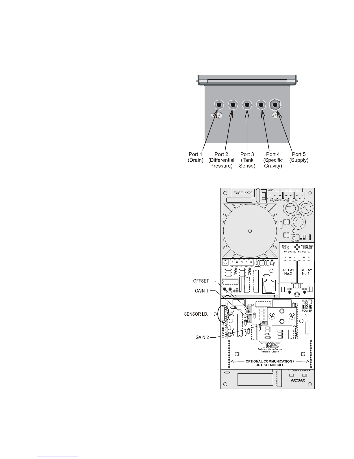
Calibration
Pneumatic Sensor Calibration
The LevelCom 100 performs a Hardware
Zero when the power is applied and
approximately every hour thereafter.
Calibration is not a routine maintenance
procedure. If you are not sure whether to
proceed with calibration please contact TMS
for guidance prior to adjusting the instrument.
This procedure must be performed by a
qualified technician.
Required Equipment
1. Calibration gauge accurate to at least
0.1" H2O (The gauge must have an
adequate range for the sensor in the
LevelCom 100).
2. Hand pump.
3. Fittings (1/8” NPT) and tubing to hook up
to the LevelCom 100.
Field Calibration Procedure
Note: This procedure assumes familiarity
with the LevelCom 100 program. If you
require assistance in entering the program
please refer to the programming sections of
the manual and the Configuration Flow
Chart. The CALIBRATE menu is an item in
the UTILITIES menu.
1. Determine the type of pressure sensor
installed in the LevelCom 100 by
inspecting the white silk-screened area of
the Pressure Sensor Circuit Board (Refer
to Figure 23 for the location).
2. Connect a fitting to PORT 1 DRAIN on
the LevelCom 100 if there is not already
a fitting in place (Refer to Figure 22 for
Figure 22 Bottom View of LevelCom 100
Figure 23 LevelCom 100 Interior
©2013 Technical Marine Service, Inc. LC-100 V2.97
Page 72
Page 73
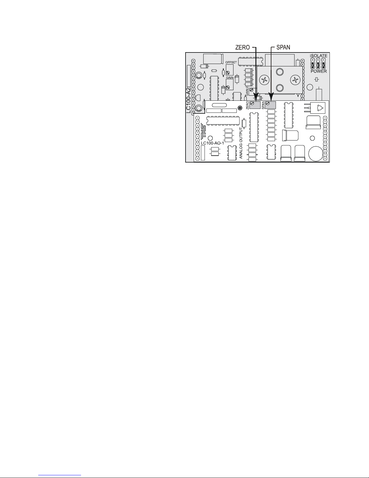
the location).
3. Enter the LevelCom 100 configuration
interface. Access the CALIBRATE
menu and select “FIELD CAL”. Press
ENTER. The output from the pressure
sensor will be displayed. This is a
number directly from the hardware. It is
not scaled into any engineering units.
4. For 15 PSI and 30 PSI sensors the
number should be near 50, for 100 PSI
sensors the number should be near 80.
For 100 PSI 16 bit sensors the situation
is more complicated. See page 75 for
special instructions if this is the case.
Figure 24 LC100-AO-1 Calibration Potentiometers
Adjust the zero pot to get the correct
reading. Press ACK and proceed to step 5.
5. Adjust the OFFSET potentiometer on the pressure sensor circuit board until the display
reads 50 if the for a 15 PSI or 30 PSI sensor, or 80 for a 100 PSI sensor (Refer to Figure
23 for the location of the OFFSET potentiometer). Press ACK when this step is done and
proceed to step 5.
6. Using the appropriate tubing and fittings, connect the calibration gauge and the hand
pump to the two opposing sides of a “T” fitting. Connect the center of the “T” fitting to the
PORT 1 DRAIN on the LevelCom 100.
7. Using the hand pump and calibration gauge apply the following pressure to the LevelCom
100 based on the pressure sensor type installed:
15 PSI 400.0" H
30 PSI 800.0" H
100 PSI 1200.0" H
O (14.45 psi)
2
O (28.90 psi)
2
O (43.35 psi)
2
100 PSI 16 bit 2400.0" H2O (86.70 psi)
The instrument will now read the applied pressure in inches of water to an accuracy of 0.1”.
If the reading is different from this value adjust the GAIN-1 potentiometer until the correct
reading shows on the display, agreeing with the reading on the calibration gauge. (Refer to
Figure 23 for the location of the GAIN-1 potentiometer)
Note: It is very important here that the hand pump and calibration gauge setup does not leak.
It is very difficult to do this adjustment correctly if there are even small leaks in the calibration
equipment.
©2013 Technical Marine Service, Inc. LC-100 V2.97
Page 73
Page 74

8. Disconnect the calibration gauge / hand pump assembly from the PORT 1 DRAIN fitting
and press ACK to recheck the zero offset value. If the zero offset value is different than it
was when measured before, repeat steps 3 through 6 until both measurements are
correct.
9. Select “CHAN-1” from the Calibrate menu. Re-connect the calibration gauge / hand
pump assembly to the PORT 1 DRAIN on the LevelCom 100.
10. Using the hand pump and calibration gauge apply the following pressure to the LevelCom
100 based on the pressure sensor type installed:
15 PSI 400.0" H2O (14.45 psi)
30 PSI 800.0" H2O (28.90 psi)
100 PSI 1200.0" H2O (43.35 psi)
100 PSI 16 bit 2400.0" H2O (86.70 psi)
11. The LevelCom 100 display should show a number near 3200. Adjust the GAIN-2
potentiometer until the correct reading of 3200 is on the display. (Refer to Figure 23 for
the location of the GAIN-2 potentiometer)
12. The calibration is complete. Remove any fittings that were attached for calibration, and
return the LevelCom 100 to normal operation. Verify that it is reading the correct depth
for the liquid in the tank.
Note: Remember that the LevelCom 100 reads out differently in different parts of the above
procedure. When you are setting the zero level the LevelCom 100 is reading out unscaled
numbers from the Analog to Digital converter on the sensor board. At this point there will be
no decimal point shown. When you are setting the span value the LevelCom 100 will display
pressure in inches of water. Since the LevelCom 100 displays with a resolution of 0.1 inches
you will see a decimal point on the display. The ACK button toggles between these two
states. It is very important that there is no pressure on the system when you toggle to the
state for setting the span. The zero reading you set is read and used to process the span
reading and the zero is recorded when the ACK button is pressed.
The readings on the display are filtered to reduce noise for readability. To reduce waiting
time press the MODE button to bypass the filter algorithm. When the MODE button is
released the filter functions as usual.
©2013 Technical Marine Service, Inc. LC-100 V2.97
Page 74
Page 75
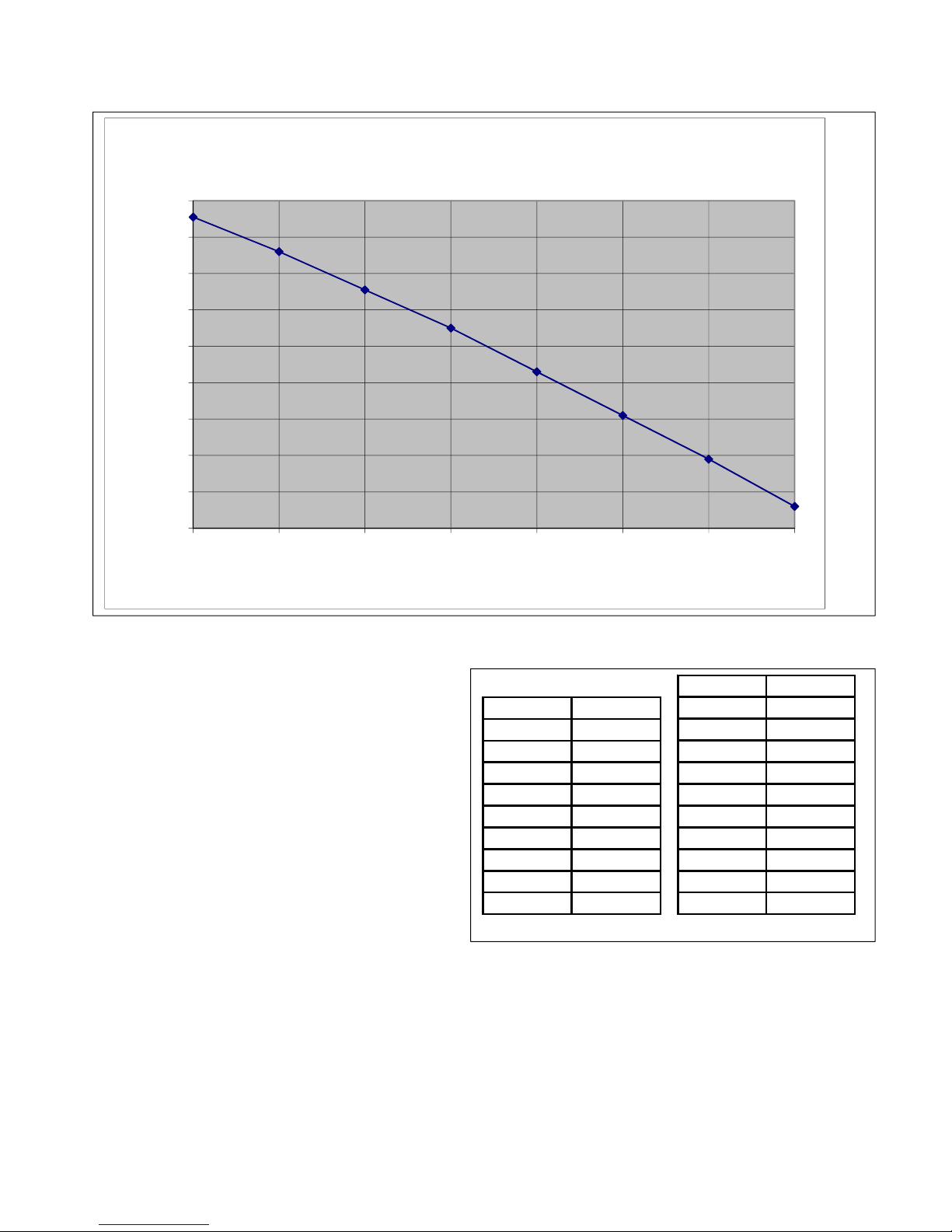
Calibration Zero Points
100
0
-100
-200
-300
-400
-500
-600
Zero Value for Calibration
-700
-800
30 40 50 60 70 80 90 100
Temperature in Deg F
Zero Offset for 16 bit Sensors
100 PSI 16 bit sensors are more sensitive to
changes in temperature. The zero point will
Deg F Zero
drift noticeably with changes in ambient
temperature. Because of this sensitivity you
cannot set a fixed value for the zero when
calibrating these sensors. Before you set
the zero point for 16 bit sensor boards you
will need to take an ambient temperature
measurement.
The above graph and the table to the right
give the zero point needed based on the
ambient temperature reading of the
LevelCom 100.
30 55
40 -40
50 -145
60 -250
70 -370
80 -490
90 -610
100 -740
Deg C Zero
037
5-52
10 -145
15 -243
20 -344
25 -451
30 -561
35 -675
40 -794
©2013 Technical Marine Service, Inc. LC-100 V2.97
Page 75
Page 76

Analog Output Calibration
The calibration of the 4-20 mA analog output can be checked and adjusted with the following
procedure. Calibration is not a routine maintenance procedure. If you are not sure whether
to proceed with calibration please contact TMS for guidance prior to adjusting the instrument.
This procedure must be performed by a qualified technician.
Required Equipment
1. Accurate current meter for reading the current output value.
2. Wire leads to connect to the LevelCom 100 analog output connector.
Note: If the analog output is being used as a control output, be sure to secure the controlled
process before you begin because you may be disconnecting the LevelCom 100 from the
controlled process, or you may be generating meaningless control signals while performing
the calibration procedure.
Calibration Procedure
1. Connect the meter to the Analog output connector. If the LevelCom 100 is set up to
power the analog output you can connect directly to the terminals, however if the output is
set up to be externally powered you will need to connect the meter into the complete
circuit.
2. Enter the LevelCom 100 program. Access the Calibrate menu and select “AN OUT”.
Press ENTER. “ZERO” will be displayed. Press ENTER. The meter should read 4 mA.
If it doesn’t, adjust the ZERO potentiometer on the analog output board until the meter
reads 4 mA. (Refer to Figure 24 for the location of the ZERO potentiometer)
3. Press the UP or DOWN keys to scroll to “SPAN” and press ENTER. The meter should
read 20mA. If it doesn’t, adjust the SPAN potentiometer until the meter reads 20 mA.
(Refer to Figure 24 for the location of the SPAN potentiometer)
4. Press the UP or DOWN keys to scroll to “ZERO” and press ENTER.
5. The meter should read 4 mA. If it does the calibration is complete, if not repeat steps 2 –
4 until the meter reads 4 mA when you enter ZERO, and 20 mA when you enter SPAN.
6. Now you can check the linearity of the output with the other items in this menu. When the
span and zero calibration is done entering the following menu items should give the
following meter readings:
25% - 8 mA
50% - 12 mA
75% - 16 mA
©2013 Technical Marine Service, Inc. LC-100 V2.97
Page 76
Page 77

This completes the test and calibration of the analog output circuit.
©2013 Technical Marine Service, Inc. LC-100 V2.97
Page 77
Page 78

Troubleshooting
The LevelCom 100 is programmed to monitor certain system functions and to display error
messages when abnormal situations are detected. These functions include:
1. Supply Air Pressure - High or low pressure.
2. Sense Line - Plugged or leaking Sense line system.
3. Internal functions - Sensor zero and
4. EEPROM functions.
The following details some of the problems, which may be encountered and corrective
actions to be taken.
Note: The LevelCom 100 is a delicate electronic instrument. Qualified individuals must
perform repairs and troubleshooting.
Instrument displays CAN’T ZERO SENSOR.
The LevelCom 100 does a power on self-test when it is powered up. Among other things,
the zero offset of the sensor circuit is read and stored in memory. The zero offset is
expected to have a value near a pre-calibrated value. This zero offset measurement is also
performed approximately once every half hour of operation. If the measured zero offset is
outside a specific range, this error message is displayed. There are a few different causes of
this condition.
Probably the most common cause is water condensed in the supply air system. The
LevelCom 100 runs a purge sequence periodically to clear the bubbler pipe and remove
accumulated water from its internal pneumatic system. However if the machine does not
purge often enough (the purge timing is programmable) water may accumulate faster than it
is removed from the system. This case can easily be verified by disconnecting the supply air
tubing to see if there is water present in the supply air. Drain any water from the air supply
lines and regulator, and reconnect the LevelCom 100. When the LevelCom 100 is powered
up, the condition should not appear.
It is also possible that the drain valve is not functioning. It may be partially or completely
blocked with foreign material, or the electrical system may not be operating the valve at all.
To test the valves enter the CALIBRATE menu (See the Configuration Flow Chart) and select
VALVES. The front panel buttons will now directly operate the valves as listed below:
©2013 Technical Marine Service, Inc. LC-100 V2.97
Page 78
Page 79

Button Valve
ENTER Supply
DOWN Specific Gravity
MENU Tank Sense
UP Differential Pressure
ACK Drain
All valves will be de-energized when this test mode is entered. With the LevelCom 100
connected to its air supply press ENTER to open the Supply valve. The drain valve is open
when de-energized so air should blow out of the Drain when the Supply valve is opened in
this test. If this doesn’t happen, first verify that the proper air supply pressure is present. If
there is too high a supply pressure present the Supply valve may not open (it will be held
closed by the air pressure). Check that the LED on the small valve interconnect circuit board
lights when the button is pressed (try the other buttons to see if any LEDs light). If the supply
valve is working, the drain valve may be plugged. Inspect the clear tubing running from the
top of the Drain valve to the aluminum manifold to see if there has been any contamination
present. If the valve is plugged it will have to be replaced.
Inspect the clear tubing running from the manifold to the sensor. If there is any
contamination in this tubing it may be the problem. Any liquid that has accumulated in the
tubing must be removed.
It is also possible that the supply valve is leaking. This is easy to detect in the valve test
mode. If the supply valve is leaking there will be a steady flow of air out of the de-energized
drain valve.
If everything checks out at this point and the error condition still appears then the sensor
circuit may need calibration. It is possible that the sensor has failed. The calibration
procedure will detect this. See the calibration procedure in this manual. Calibration should
be done only after all other possibilities have been exhausted.
Instrument displays EEPROM FAILURE.
This message indicates trouble with the EEPROM (Electrically Erasable Programmable Read
Only Memory) memory that is used to hold the LevelCom 100 configuration. If this message
occurs when the LevelCom 100 is powered up it means that there were problems reading the
configuration from the EEPROM. If this message occurs when changing the LevelCom 100
configuration it means that there were problems detected while writing new information to the
EEPROM. In this case the new information was not completely stored, but the old
information was probably at least partially modified. The message could mean that there has
been a true electrical failure of the EEPROM, however this is not the only possibility. The
following will describe some tests to determine the cause of the problem.
Turn the LevelCom 100 off and after a short time restore power. If the message does not
appear this time it may indicate that the problem was caused by electrical noise getting into
©2013 Technical Marine Service, Inc. LC-100 V2.97
Page 79
Page 80

the LevelCom 100 system. This could happen if there are relays installed and the relays are
driving a large inductive load, like a motor or a solenoid (please note that the relays are rated
“Pilot Duty Only”). If the relay is driving a DC relay or solenoid there should be a
freewheeling diode in the circuit or else large voltage spikes will be generated on the control
circuit when the relay contacts open. These spikes can generate powerful radio frequency
pulses that can effect nearby electronic devices. Similarly if the relay is operating an AC
motor, either directly, or through a slave relay both the starting and stopping of the motor can
generate voltage spikes on the power lines and these spikes can possibly affect the
LevelCom 100 electronics. In this case putting capacitors across the motor terminals can
sometimes help.
This problem will not always show up immediately in a new installation. The LevelCom 100
always verifies the updated contents of the EEPROM as it writes new information. If this
verification fails, the LevelCom 100 tries again and signals a failure only after a number of
verification failures. The LevelCom 100 stores multiple copies of the configuration and there
is unused space in the EEPROM of a new LevelCom 100 that can be used for configuration
information if there is a partial failure of the EEPROM. The electrical noise described above
can interfere with EEPROM operations in extreme cases. In this case there will not actually
be a failure of the EEPROM but because of the electrical noise, there may have been
verification failures causing the LevelCom 100 to use new areas of the EEPROM. When all
available space is used up the LevelCom 100 will generate the EEPROM FAILURE
message. As a result the machine will work well for a while and then start showing the
EEPROM FAILURE condition. A way to check for this is to select the ERASE ALL MEMORY
option in the MEMORY menu. This will completely erase any configuration information in the
EEPROM and the LevelCom 100 will need to be reconfigured before being put back into
operation. Then if the machine works well for a while and once again starts showing the
EEPROM FAILURE condition electrical noise is probably causing the trouble.
If erasing the EEPROM does not get rid of the condition then there is probably something
wrong with the EEPROM and it will need to be replaced.
Instrument displays CHECK AIR.
This message will be displayed if there is either insufficient or excessive air pressure for
proper machine operation. Check the regulator to make sure that the machine is getting
supply air. If supply air is present make sure that the pressure is not too high. If the input air
pressure is too high the supply valve will not be able to open. If there is a gauge on the
regulator, make sure that this gauge is reading correctly. Finally make sure that there is not
water in the supply air lines or that the regulator bowl is not full of water. Loosen the supply
air fitting at the LevelCom 100 to make sure that air can flow to the LevelCom 100.
If all these things check out there may be a problem with the Supply valve. Use the VALVES
utility in the calibrate menu. Operate the Supply valve manually and air should come out of
the Drain port. If nothing happens make sure that the LED on the valve board lights when
the ENTER button is pressed to operate the valve. If the LED doesn’t light make sure that
the flat cable is properly plugged onto the connector on the valve board. If the connector is
©2013 Technical Marine Service, Inc. LC-100 V2.97
Page 80
Page 81

attached and the LED still doesn’t light and the valve does not operate then there is probably
an electrical problem on the main controller board. If the LED lights but the valve does not
operate the Supply valve has probably failed.
The CALIBRATE menu.
This menu provides utilities for testing and calibrating the LevelCom 100. It is found in the
UTILITIES menu. Below are descriptions of the items in this menu.
The CHAN-0 item gives direct access to the main output from the sensor circuit. When this
item is activated the display shows the output of the analog to digital converter. This output
is also useful to verify that the sensor circuit is functioning. When this item is activated the
valves are all de-energized. The Drain valve is run as a normally open valve so the Drain
port now gives access to the pressure sensor input. It is easy to verify that the sensor circuit
is working by applying a little air pressure to the Drain port and verifying that the numbers on
the display increase with increasing pressure. The ESCAPE key is used to exit this utility.
The CHAN-1 item works exactly like the CHAN-0 item. It gives access to a secondary signal
from the sensor circuit that is used primarily for control of the Supply valve. The ESCAPE
key is used to exit this utility.
The VALVES item gives direct access to the solenoid valves. When activated the front panel
buttons are used to activate the valves.
The following list shows which buttons run which valves.
Button Valve
ENTER Supply
DOWN S.G.
MENU Tank Sense
UP D.P.
ACK Drain
The ESC key is used to exit this utility. This item is useful for testing the valves. This utility
must be used with some caution however. In normal operation the LevelCom 100 is
continually checking the pressure and the Supply valve will be closed if the pressure is too
high. This is done to protect the sensor. When this utility is used the operator must verify
that the sensor does not get exposed to too high a pressure. This is NOT a way to clear a
plugged bubbler pipe for example; the sensor could be permanently damaged this way. It is
also possible, depending on the sense line installation, that liquid from the tank could siphon
back to the LevelCom 100 if the Tank Sense valve is held open for an extended period. This
could result in damaging contamination to the LevelCom 100 and some danger to the
operator depending on the liquid in the tank. It is the responsibility of the operator to use
this utility in a safe manner.
The RELAYS item gives direct access to the relays. When activated the UP button operates
Relay 1, the DOWN button operates Relay 2. The relays de-energize on entering this utility.
©2013 Technical Marine Service, Inc. LC-100 V2.97
Page 81
Page 82

Pressing the appropriate button energizes the associated relay. This is useful for testing the
function of the relays and the condition of the relay contacts. It is a useful utility when wiring
to external alarm systems or control devices. The ESCAPE key is used to exit this utility.
The HORN item is used to test the installed Sonalert device in the LevelCom 100. It is useful
only if the horn option is installed. The ESCAPE key is used to exit this utility.
The DISPLAY item is used to test the entire display. When activated the character display
will show a rotating pattern that lights all segments in a digit including the decimal point. The
UP key will cause the bar graph to light starting from the bottom to the top. The DOWN key
will cause the bar graph lights to go out starting from the topmost lit segment down to the
bottom. The alarm setpoints will remain lit when they are in the dark part of the bar graph,
and they will be dark when they are in the lit part of the bar graph. The ESCAPE key is used
to exit this utility.
The BUTTONS item is used to test the front panel buttons. When active the display will
show the name of the last button pressed. This is useful if there is the possibility that one or
more of the buttons have failed. Simultaneously press the ENTER key and the ESCAPE key
to exit this utility.
If the machine has the analog output option installed there will be another utility available
called AN OUT . This is used for calibration and testing of the analog output. There are five
menu items in this utility. When the display shows ZERO, pressing ENTER forces the analog
output to 4 mA. When the display shows SPAN, pressing ENTER forces the analog output to
20 mA. These are intended for use in calibrating the analog output. These two functions are
used while adjusting the analog output span and zero pots found on the Sensor board in the
LevelCom 100. The 25%, 50%, and 75% items work the same way forcing the analog output
to 8 mA, 12 mA, and 16 mA respectively. They are useful for verifying the linearity of the
analog output, and are also useful for testing the field devices driven by the analog output.
Again it is the responsibility of the operator to use this utility in a safe manner. If the analog
output is used as a control output the controlled process must be secured before using this
utility.
If the LevelCom 100 is configured to communicate with LevelCom 101 digital repeaters there
will be a menu item available called DIGITAL COMMUNICATION. Under this item are a
number of utilities for troubleshooting the digital communication interface.
Finally the last item in this menu is the FIELD CAL procedure already described in the
calibration section on page 72.
Analog Output Troubleshooting
The analog output is a 4-20 mA output. The output may be run as a self-powered output (in
which case the LevelCom 100 provides power) or as an externally powered. When set up to
©2013 Technical Marine Service, Inc. LC-100 V2.97
Page 82
Page 83

be externally powered the analog output circuit is electrically isolated from the rest of the
LevelCom 100. If the analog output does not work check the following:
Check the connections to the Analog Output terminals. Make sure the correct connector is
wired, and verify the polarity of the wiring. It may be that something is wired backwards in
the loop. Refer to the wiring diagrams in the installation section of the manual.
Check the jumpers on the sensor board and make sure that the analog output is configured
as self-powered or isolated. Refer to Figure 16 and Figure 15 for the proper jumper settings.
If the jumpers are in the wrong position, the output will not work.
If your machine has the LC100-A2 or –A3 sensor input circuit board, the analog output is
contained in a small circuit board attached to the sensor input board. There is an LED on the
analog output board next to the ZERO potentiometer that flashes to indicate that the board is
functioning. Refer to Figure 24 for location of this LED. If this LED is not flashing the analog
output module has probably failed, and should be replaced.
Digital Repeater Communication Troubleshooting
The Digital communication output is based on an RS-485 physical interface. It uses the
connector for the Analog Output to connect its signal wiring. If you are experiencing trouble
communicating with LevelCom 101 Repeaters using the digital communication option, check
the following.
There is an LED on the LC101-DC1 Digital Communication Interface board, mounted on the
sensor input board inside the LevelCom 100. If the interface board is functioning correctly,
this LED will flash. If this LED is not flashing the board may have a problem. A second
check for this is to enter the configuration menus and see if the DIGITAL COMMUNICATION
option is available under the OUTPUTS menu. The communication interface is automatically
detected when the LevelCom 100 is powered up. If the interface is not working, you will find
the ANALOG OUTPUT option under the OUTPUTS menu rather than the DIGITAL
COMMUNICATION option. In this case the communication interface board will have to be
replaced.
Check to see that the jumpers on the sensor board are set up correctly, see Figure 16 and
Figure 15. The jumpers need to be set as shown for Externally Powered Loop.
Make sure that the polarity of the wires in the connector is correct. You could try swapping
the polarity to see if things work.
If the jumpers are set correctly make sure all ID numbers are set up correctly on both the
LevelCom 100 and the LevelCom 101 Repeaters. If these check out, and if they were just
configured try cycling power to all machines. To check these configurations refer to page 62.
©2013 Technical Marine Service, Inc. LC-100 V2.97
Page 83
Page 84

The DIGITAL COMMUNICATION tools under the CALIBRATE menu can be used to check
the function of the digital communication module in the LevelCom 100. The items under this
menu are listed here with their function.
COMM STATE: This item is of limited use for troubleshooting. It is used for development of
the software on the communication module itself.
HOST TIMEOUT COUNT: This counts attempts to communicate with the installed module
that failed for some reason. If this counter is counting up there may be a physical problem
with the module. The module was successfully detected by the LevelCom 100 on startup but
it is having trouble communicating.
MOD FAIL COUNT: If the LevelCom 100 tries to communicate with the installed Digital
Communication module and the communication fails this counter is incremented. If this
counter is counting up it means that there might be problems with the installation of the
communication module. Check that the screws securing the communication module to the
sensor circuit board are installed and tight.
MOD SER FAIL COUNT: This counter counts failures to communicate with LevelCom 101
repeater modules. If this counter is counting it suggests a wiring problem between the
LevelCom 100 and the repeater. Alternately the repeater may not be configured with the
proper address. At present there is a problem with the program on the digital communication
module and this counter will increment during normal operation.
MOD SER NACK COUNT: This counter counts NO ACK messages sent back from the
repeaters. If this counter is counting there is probably intermittent trouble with the wiring
between the LevelCom 100 and the repeaters. Messages are getting through but some are
garbled and not readable by the repeater. The repeater sends a NO ACK message to signal
this condition.
REPEATER STATE: There are four items in this, selected by using the UP or DOWN
buttons. Each possible repeater is shown, here, listed as ID1 – ID4. The state of a repeater
is one of three possibilities. If it is set up to communicate and communication is functioning it
will show as ID1 GOOD. If it is set up but not communicating it will show as ID1 NO COMM.
If it is disabled (network address set to 255) it will show as ID2 NOT USED. This item can
help to identify problems if there are multiple repeaters and some are working and some are
not. This can point to configuration issues in the repeaters, network addresses not set up
correctly, or trouble with the wiring between the repeaters and the LevelCom 100.
Modbus Troubleshooting
If the LevelCom 100 is not communicating on the Modbus interface first check that it is
configured to use the Modbus protocol.
After the wiring is verified the next thing to check is the wiring. Verify that the communication
interface is wired correctly; use Appendix A as a guide for wiring.
©2013 Technical Marine Service, Inc. LC-100 V2.97
Page 84
Page 85

Verify that the Modbus Address is set correctly. See Modbus Communication in the
advanced Setup section of this manual.
Verify that the baud rate and parity settings are correct. There are some complications with
the parity settings, especially in the case where no parity information is sent. In
communications with desktop computers the most common parity setting is N-8-1, no parity,
8 bits per byte, 1 stop bit. In some PLCs though the only available no parity setting is
equivalent to N-8-2, no parity, 8 bits per byte, 2 stop bits. When there is a mix up between
these types the machines will communicate sometimes, but not reliably, or only in one
direction. The second stop bit can sometimes be detected as the start bit of the next byte if
an N-8-2 setup is communicating with a N-8-1 setup. This results in framing errors at the
receiving end and failed communication. See the Serial Communication section on page 30.
Under the COMM SETUP menu in the UTILITIES menu there is an item called DIAGS. The
standard Modbus error counters are accessible here and they can be useful to help
troubleshoot Modbus communication problems. The items in this menu are as follows
EVENT COUNT: Counts messages sent to the LevelCom 100 that were successfully
received and processed.
EXCEPTION COUNT: Counts messages sent to the LevelCom 100 that were successfully
received that generated exceptions. These are messages that cannot be serviced because
of parameters out of bounds, or there is a command that is not supported by the LevelCom
100.
MESSAGE COUNT: Counts all messages on the Modbus network, including messages not
directed at the LevelCom 100.
CRC ERROR COUNT: Counts messages sent to the LevelCom 100 who’s calculated CRC
did not agree with the CRC in the message. This suggests noise in the network is garbling
message traffic. If this counter is counting continuously check the network wiring for faults or
bad connections.
CLEAR COUNTERS: This utility is used to clear the Modbus counters. This is useful when
you start troubleshooting to see what the counters are doing now. If the network has been
operating continuously for a long time there may be non-zero count values on the error
counters even if the events counted are relatively rare. It is important to know if there is a
real problem or not. Clear the counters at the beginning of a troubleshooting session to
avoid confusion. The values of the error counters are also remotely readable through the
Modbus interface. See the Modbus register map section on page 91
The HARDWARE Menu
There is a special menu on the LevelCom 100 that is used to configure or read installed
hardware options. Most of these options are indications only and are not changeable by the
©2013 Technical Marine Service, Inc. LC-100 V2.97
Page 85
Page 86

operator. They are automatically detected by the LevelCom 100 when it first starts operation,
and the devices detected are shown here for troubleshooting. There are some options that
can be changed here though; Automatic Specific Gravity, Differential Pressure, Passive
Gauge, and Sample Timing.
It is very important to understand the function of the configurable parameters before
changing them. If these are set up incorrectly the machine will not function correctly.
Operators should contact TMS before changing any of these settings. It is important to
understand what each option does. The following section describes all options under the
HARDWARE.
Accessing the Hardware menu
First you must set up temporary a password in the LevelCom 100 if there isn’t already a
password programmed (A for example). If there is already a password programmed into the
machine you don’t have to change it. You need a password in the machine so that you will
be asked to enter a password before entering the operator interface.
Now enter the configuration menus, when the machine asks for you to enter the password,
use the special password SETXYZ.
After entering the password the machine will display SYSTEM. Press UP and the machine
will display UTILITIES.
Press ENTER, the machine will display COMM SETUP. Press UP and the machine will
display HARDWARE. This is the special hardware configuration menu. You must enter the
configuration interface using the password SETXYZ to have access to this menu. Normally it
isn’t available in the UTILITIES menu.
Press ENTER, the machine will display 15 PSI.
The menu begins with a list of possible pressure sensor types and other optional hardware
installed. You will see an asterisk * in the rightmost character in the interface identifying the
options installed. If an option can be activated by the operator, the MENU key is pressed to
activate or de-activate that item. In this case the asterisk indicates that the item is active.
The list with descriptions of each item is as follows. You will use the DOWN arrow button to
scroll through this list:
15 PSI: A 15 psi sensor is installed. Not modifiable.
30 PSI: A 30 psi sensor is installed. Not modifiable.
100 PSI: A 100 psi sensor installed. Not modifiable.
©2013 Technical Marine Service, Inc. LC-100 V2.97
Page 86
Page 87

100 PSI DEEP: A 100 psi pressure sensor with optional double range span setup. This
option is not produced any more but will be encountered on older installations that are
upgrading firmware. This option will be needed on any firmware upgrade if there is a D after
the firmware revision number and the installed sensor is a 100 PSI sensor, for example
V2.83D. To activate this item press the MENU key and an asterisk will appear in the right
most character in the display. If the item is already activated and the operator wishes to deactivate the item, press the MENU key and the asterisk will disappear. Press Enter to save
this selection.
100 PSI 16 BIT: A 100 psi sensor is installed with the optional 16 bit A/D converter. Not
modifiable.
RELAYS: The optional relay module is installed. Not modifiable.
A OUT: The optional analog output module is installed. Not modifiable. Note this item will
show an asterisk if the optional Digital Communication Interface Controller is installed. This
is normal.
A IN: The LevelCom 100 is built to take input from an external 4-20 mA transmitter rather
than the typical internal sensor. Not modifiable. This option is obsolete and should not be
encountered.
HORN: The optional piezoelectric horn is installed in the machine. Not modifiable.
S G: The machine is built to read specific gravity. This option uses another sense line
system and must have another output valve built into the pneumatic manifold to function.
This item is configurable through this menu. To activate this item press the MENU key and
an asterisk will appear in the right most character in the display. If the item is already
activated and the operator wishes to de-activate the item, press the MENU key and the
asterisk will disappear. Press Enter to save this selection. It is important to verify that the
specific gravity sense line and valve are present. Activating this item on a standard
LevelCom 100 can lead to problems in normal operation and confusing error messages.
DIFF P: The machine is built to read the pressure in the tank above the liquid. This option
uses another sense line and must have another output valve built into the pneumatic
manifold to function. This item is configurable through this menu. To activate this item press
the MENU key and an asterisk will appear in the right most character in the display. If the
item is already activated and the operator wishes to de-activate the item, press the MENU
key and the asterisk will disappear. Press Enter to save this selection. It is important to
verify that the differential pressure sense line and valve are present. Activating this item on a
standard LevelCom 100 can lead to problems in normal operation and confusing error
messages.
PASSIVE GAUGE: The machine is configured to read a sense line only. It will not apply air
to the sense line. In rare instances two machines are used to read a single sense line. One
machine controls the air to the sense line, and operates normally. The other machine is
©2013 Technical Marine Service, Inc. LC-100 V2.97
Page 87
Page 88

configured as a passive gauge and will not apply any air to the sense line. This configuration
prevents the two machines from interfering with each other. To activate this item press the
MENU key and an asterisk will appear in the right most character in the display. If the item is
already activated and the operator wishes to de-activate the item, press the MENU key and
the asterisk will disappear. Press Enter to save this selection.
SAMPLE TIMING: This parameter is used to set the time the machine waits after putting a
charge of air on the line to take a sample of the line pressure. When using longer sense
lines this waiting time must be increased.
Press ENTER to view the current value. When you are viewing the parameter you can use
the UP and DOWN keys to change the value. When the desired value is shown on the
display press ENTER to save the new value.
This timing parameter does not have units, however a larger value of the timing parameter
results in longer delay times in sampling. Lengths of up to 600 feet of poly tubing have been
tested and below are suggested timing parameter values. You should only set the timing
parameter large enough to get correct operation. You don’t want to unnecessarily slow the
machine’s operation.
Timing parameter values for different lengths of ¼ inch poly tubing
100 feet 1
200 feet 3
300 feet 7
400 feet 10
500 feet 14
600 feet 18
You can tell if the timing parameter is too small by watching the machine sample the sense
line. The machine will put two or three charges of air on the sense line in a normal sample
operation. If the readings are not consistent between these charges of air the machine will
put a larger charge of air on the line which you can hear. After all charges of air the display
is updated. You can see the measured depth rise when the machine samples, and after the
sample operation is complete the depth will settle back to down to a lower value.
When the larger blast of air is triggered on every sample operation, and especially if the
measured depth changes much during the sample operation, the machine will eventually
indicate a leak.
Once the timing parameter is set up correctly the leak detection logic functions correctly, and
if the machine still indicates a leak condition there is probably a real leak in the sense line.
The above timing parameter values were derived from tests at TMS. Different sense line
materials have different effects on timing. For instance a LevelCom 100 will function
©2013 Technical Marine Service, Inc. LC-100 V2.97
Page 88
Page 89

correctly with the default timing parameter value of 1 on over 300 feet of ¼ inch copper
tubing. Poly tubing has a greater resistance to gas flow than similar sized copper tubing.
If you need to set the parameter very differently from the values shown in the table above
and you are using ¼ inch tubing, there is probably something wrong with the installation.
The sense line may be kinked somewhere causing a near complete blockage. Check the
installation first before adjusting the value of this parameter from the normal value of 1.
Adjusting this parameter is the last resort and should not be done without eliminating all other
sense line problem sources first.
©2013 Technical Marine Service, Inc. LC-100 V2.97
Page 89
Page 90
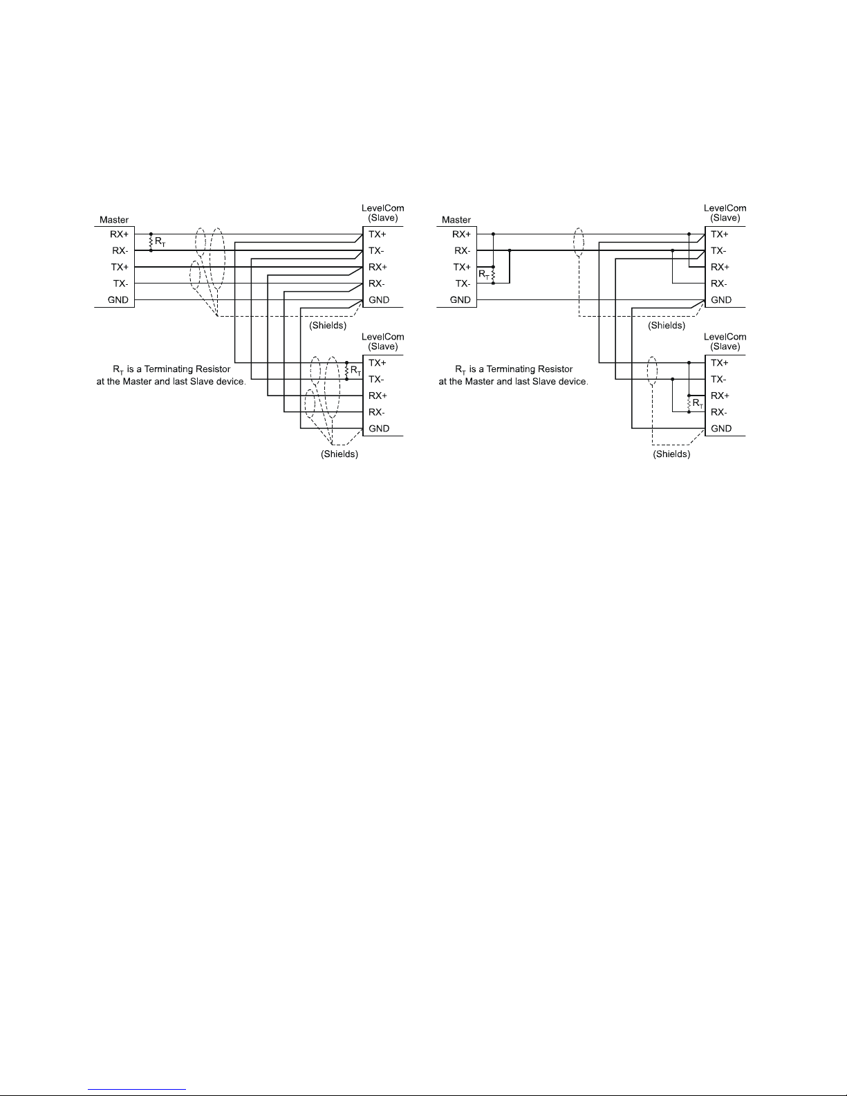
Appendix A
Serial Network Wiring Diagrams
Figure 26 5 Wire RS-422/485 Wiring
The above diagrams show the wiring for various RS485 installations. Both 5 wire and three
wire networks are supported. See the documentation on the master device for the
connections. There is not a standard pinout for 9 pin D subminiature connectors so none is
shown here. If you are using a plug in expansion card in a PC the documentation for the
card will show the correct pinout for the connectors.
RS-485 connections may be wired to single nodes or multiple nodes. These drawings show
multiple node connections
For low speed communications terminating resistors may not be needed, check the
documentation with the computer interface for the value of these resistors if needed.
Figure 25 3 Wire RS-422/485 Wiring
©2013 Technical Marine Service, Inc. LC-100 V2.97
Page 90
Page 91
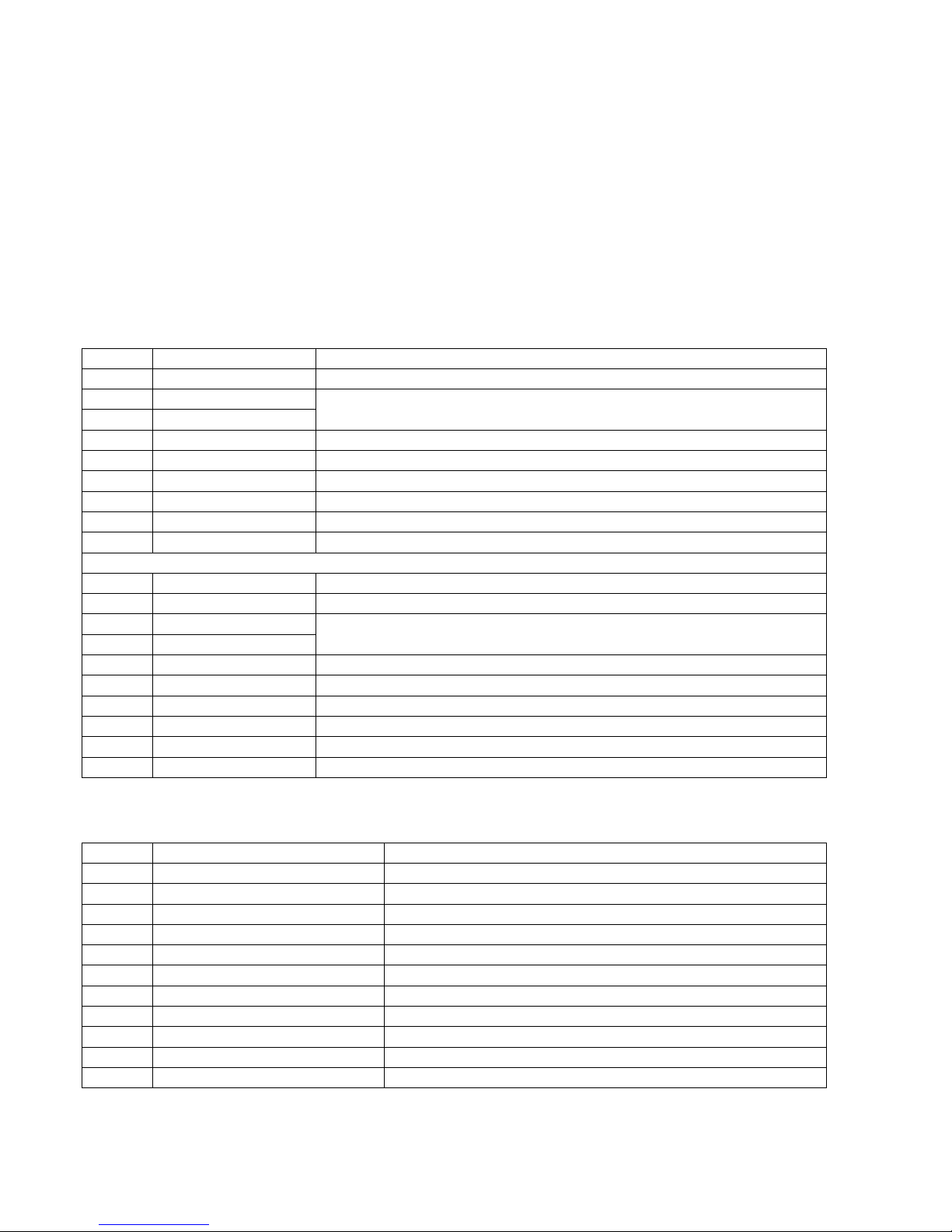
Appendix B
Modbus Register Values
Below is a map of the input/output registers and coils available in the LevelCom 100 for
Modbus communications.
Read functions:
30001 Level Level in 0.1 inches
30002 Specific Gravity Specific Gravity x 1000
30003 Volume (1) Volume is combined in registers 30003 & 30004 to form a long
30004 Volume (2)
30006 Status Bits Status codes as bits. See note 2 below.
30007 Max Depth Programmed Max Depth in 0.1 inches
30008 HiHi Alarm HiHi alarm set point in 0.1 inches
30009 Hi Hi alarm set point in 0.1 inches
30010 Lo Lo alarm set point in 0.1 inches
30011 LoLo LoLo alarm set point in 0.1 inches
The above registers are mirrored in the following holding registers:
40001 Level Level in 0.1 inches
40002 Specific Gravity Specific Gravity x 1000
40003 Volume (1) Volume is combined in registers 30003 & 30004 to form a
40004 Volume (2)
40006 Status Bits Status codes as bits. See note 2 below.
40007 Max Depth Programmed Max Depth in 0.1 inches
40008 HiHi Alarm HiHi alarm set point in 0.1 inches
40009 Hi Hi alarm set point in 0.1 inches
40010 Lo Lo alarm set point in 0.1 inches
40011 LoLo LoLo alarm set point in 0.1 inches
The following coil bits signal various conditions in the LevelCom as noted:
10001 HiHi Alarm 1 = HiHi alarm activated
10002 Hi Alarm 1 = Hi alarm activated
10003 Lo Alarm 1 = Lo alarm activated
10004 LoLo 1 = LoLo alarm activated
10005 Big Number See note 1 below
10006 Loop failure 1 = 4-20 mA loop failure
10007 SG line over pressure 1 = SG sense line is over pressurized (plugged)
10008 DP line over pressure 1 = DP sense line is over pressurized (plugged)
10009 EPROM failure 1 = EPROM failure
10010 Sense line leak 1 = Main sense line is leaking
10011 Sense line over Pressure 1 = Main sense line is over pressurized (plugged)
10012 Check Air 1 = Low supply air pressure
integer. See note 1 below.
long integer. See note 1 below.
©2013 Technical Marine Service, Inc. LC-100 V2.97
Page 91
Page 92
Write functions:
Writing values to the following registers allows the specific gravity and alarm set points to be
modified remotely. Note that writing to these registers will update the configuration of the
LevelCom 100.
The normal value of these registers is 0. A non-zero value in one of these registers causes
the LevelCom to update the internal configuration, and after this is done, the LevelCom
writes a 0 value back to the register. This return to 0 can be used as a signal that the
operation is complete.
40012 Specific Gravity Specific Gravity x 1000
40013 HiHi Alarm HiHi alarm set point in 0.1 inches
40014 Hi Alarm Hi alarm set point in 0.1 inches
40015 Lo Alarm Lo alarm set point in 0.1 inches
40016 LoLo Alarm LoLo alarm set point in 0.1 inches
Setting the following coil bits triggers the actions as noted. When the action is initiated by the
LevelCom 100 the coil is cleared and reset to "0".
00001 Purge Now Triggers the purge cycle
00002 Sample Now Forces a new level sample
00003 Acknowledge Allows remote acknowledge for alarm and fault conditions
00004 Restart Restarts the LevelCom
Notes:
Base units and Big Number
Level and volume are stored in the LevelCom 100 in specific base units. These values are
scaled for display on the LevelCom 100 based on the desired output units. The Modbus data
is given only in the base units and must be converted by the user application.
Level is reported by the LevelCom 100 in 0.1 inches. The conversion factors for the other
units available in the LevelCom 100 are as follows:
Feet = 0.1 inches / 120
Centimeters = 0.1 inches x .254
Meters = 0.1 inches x .00254
Volume is reported by the LevelCom 100 in two possible base units. You must check the Big
Number flag in output register 10005. If this coil is set then the base output units are full
liters, if the flag is not set the output units are in 0.1 liters. This flag will only be set if an
extraordinarily large volume or weight value is input into the Tank Table during the
programming of the LevelCom 100. The default condition is Big Number = 0, volume
reported in 0.1 liters.
©2013 Technical Marine Service, Inc. LC-100 V2.97
Page 92
Page 93

Assuming Big Number = 0 the conversion factors for the other units available in the
LevelCom 100 are as follows:
Gallons = 0.1 liters / 37.85306
K Gallons = 0.1 liters / 37853.06
Liters = 0.1 liters / 10
K Liters = 0.1 liters / 10000
Cubic Feet = 0.1 liters / 283.1605
Barrels = 0.1 liters / 1589.829
These conversion factors must be divided by 10 if the Big Number flag is set and the base
units are liters.
Volume Format
Volume is a long (32 bit) integer. Since the registers are only 16 bits long the volume is
stored in two registers. To get the actual volume registers 30003 and 30004 must be
combined in the following way:
Volume = ( (register 30003) * 65536 ) + (register 30004)
Registers 30006 & 40006 - Status Bits
These registers can be used in place of the 1XXXX coil registers. The bit functions
are defined below.
EPROM Failure 0x0001
Check Air 0x0002
Sense line over pressure 0x0004
Loop failure 0x0008
Sense line leak 0x0010
SG sense line over pressure 0x0020
DP sense line over pressure 0x0040
SG sense line leak 0x0080
Big Number flag 0x0100
HiHi Alarm 0x8000
Hi Alarm 0x4000
Lo Alarm 0x2000
LoLo 0x1000
©2013 Technical Marine Service, Inc. LC-100 V2.97
Page 93
Page 94

Configuration Interface Map
The following pages are a map of the configuration interface. Use these maps to find your
way around the interface.
First a simple map is given as a general guide to the interface. This can be used as a quick
reminder for operators who already have experience configuring LevelCom 100s. Many
details are left out in this diagram to make it fit on a single page.
Following the simple map is a detailed map of the complete configuration interface. This
map is spread out over six pages so be careful in using it. Most of the main menu items are
documented on a single page.
On the first page of the detailed map is a key to the symbols used in the map. If you don’t
understand the symbols you should re-read the sections of this manual and refer to this map
as you read to get familiar with the layout of the map. Once you are familiar with the
configuration interface you should be able to get around quickly just using the map.
Generally to navigate the configuration interface you use the UP and DOWN arrow buttons to
move through the items in a single menu, you use the ENTER button to move one level into
the interface, and you use the ESCAPE button to move one level back. In the diagram this
corresponds to moving to the right using the ENTER button, and moving to the left using the
ESCAPE button.
©2013 Technical Marine Service, Inc. LC-100 V2.97
Page 94
Page 95
Simplified Configuration Interface Map
NORMAL
OPERA TION
HOT MENU ITEM
SYSTEM
OUTPUT S
HOT MENU
SETUP
NEW
PASSWORD
UTILITIES
DISPLAY
SETUP
SEN SOR
RANGE
SPECIFIC
GRAVITY
PURGE
NOW
LIGHTS
HORN
RELAY 1
RELAY 2
ALARM
SETPOINTS
ANALOG
OUTPUT
DIGITAL
COMMUNIC ATION
COMM
SETUP
CALIBRATE CHAN 0
MEMORY
DEPTH
UNITS
VOLUM E
UNITS
WEIGHT
UNITS
DISPLAY
UNITS
TA N K
TABLE
SAMPLETIMING
PURGE
PURGE
DURATION
GAU GE
CONT ROL
NETWORK
ADDRESS
BAUD RATE
PAR ITY
PROTOCOL
DIAGS
CHAN 1
VALVES
RELAYS
HORN
DISPLAY
BU TT ON S
ANALOG
OUTPUT
FIELD CAL
WRIGHT OVER BACKUP
RESTORE FROM BACKUP
ER A SE C URR ENT S E TU P
OR
ERASE ALL
DIGITAL
COMMUNIC ATION
LIQUID LEVEL
COMPUTER
Version 2.92 D ATE 6/2008
Technical Marine Serv ice, Inc.
Portland, Oregon
©2013 Technical Marine Service, Inc. LC-100 V2.97
Page 95
Page 96
Detailed Configuration Interface Map
LIQUID LEVEL
COMPUTER
Program Fl ow Ch art
Version 2.92 DATE 6/2008
Technical Marine Service, Inc.
Portland, Oregon
MO DE BUTTON
ESCAPE BUTTON
ENTER BUTTON
UP BU TTO N
DOWN BU TTO N
H M
K E Y
USED TO ENTER PROGRAM
MO DE AND SELECT OR
DES ELECT PARAMETERS
EXIT LEFT TO THE
PREVIOUS BOX
ADVANCE RIGHT TO THE
NEXT BOX WHILE SAVING
CHANGES TO THE CURRENT
CONFIGURATION
MOVES UP THROUGH
A MENU
MOVES DOWN THROUGH
A MENU
MESSAGE DISPL AYED AT
EACH STAT ION
WHERE VARIABLES ARE
ENTERED WITH UP AND
DOWN BU TTONS
MENU B UTTON SETS FL AG
TO ACTIVATE OPTION
ITEMS THAT CAN BE ADDED
TO TH E” HO T MENU”
NORMAL
OPERATION
MODE
IF HOT MENU EXISTS
THEN IF NOT
“HOT MENU”
FLASHES
HOT MENU ITEM
HOT MENU ITEM
HOT MENU ITEM
ETC.
CONFIGURE
SYSTEM
THEN IF NOT
EN TER
PASSWOR D
UP BUTTON CALLS FOR A NEW READING
ENTER BUTTON DISPLAYS UNITS OF MEASURE THEN
RET URNS TO NORMAL OPE RATION
ESCAPE BUTTON DISPLAYS ANY ALTERNATE ACTIVE
DISPLAY UNITS FOR 20 SECONDS
IF PASSWORD EXISTS
******
IF PASSWORD IS CORRECT
IF NOT THEN
©2013 Technical Marine Service, Inc. LC-100 V2.97
Page 96
Page 97
SYSTEM INCHES
DISPLAY
SETUP
DEPTH
UNITS
VOLUM E
UNITS
WEIGHT
UNITS
DISPLAY
UNITS
FEET
FEET & INCHES
CENTIMETERS
METERS
ULLAGE
NOT USE D
GALLONS
K GA LLONS
LITERS
K LITERS
CUBIC FEET
BARRELS
ULLAGE
NOT USE D
SHORT TONS
LONG TONS
METRIC TONS
ULLAGE
DEPTH
VOLUM E
WEIGHT
ONLY APPEARS IF
MORE THAN ONE
DISPLAY UNIT IS ACTIVE
TA N K
TABLE
MAX DEPTH MAX V OR W
D 9
D 8
D 7
D 6
D 5
D 4
D 3
D 2
D 1
BUBBLER
TO BOTTOM
S. G.
DISTANCE
V9 O R W9
V8 O R W8
V7 O R W7
V6 O R W6
V5 O R W5
V4 O R W4
V3 O R W3
V2 O R W2
V1 O R W1
TANK TABLE W ILL
ASK FOR DEPTHS AND
VOLUME OR WEIGHT
WHIC HEVER IS ACTIVE
AND SELECTED
AS THE DISPLAY UNIT
©2013 Technical Marine Service, Inc. LC-100 V2.97
Page 97
Page 98
SAMPLETIMING AUTO
FAST
10 SECONDS
ETC.
1 HOUR
DEMAND
PURGE 1 HOUR
2HOUR
ETC.
7DAY
DEMAND
PURGE
DURATION
H M
WILL NOT APPEAR IF
SENSING INPUT IS SUPPLIED
FROM AN EXTERNAL TRANSMITER
OUTP UTS
SEN SO R
RANGE
SPECIFIC
GRAVITY
PURGE
NOW
LIGHTS
HORN
ONLY APPEARS IF
SENSING INPUT IS SUPPLIED
FROM AN EXTERNAL TRANSMITER
IF AUTO S.G. OPTION IS INSTALLED
THEN IF NOT
FILTER
RUNS PURGE CYCLE AND
RETURNS TO NORMAL OPER ATIO N
HI HI
HI
LOW
LOW LOW
LATCH
HI HI
HI
LOW
LOW LOW
LATCH
ANY FLAGS SET FOR HORN OR RELAYS
WILL AUTOMATICALLY BE ADDED HERE
ONLY APPEARS IF
OPTION IS INSTALLED
H MAUTO
H MMANUAL
H M
©2013 Technical Marine Service, Inc. LC-100 V2.97
Page 98
Page 99
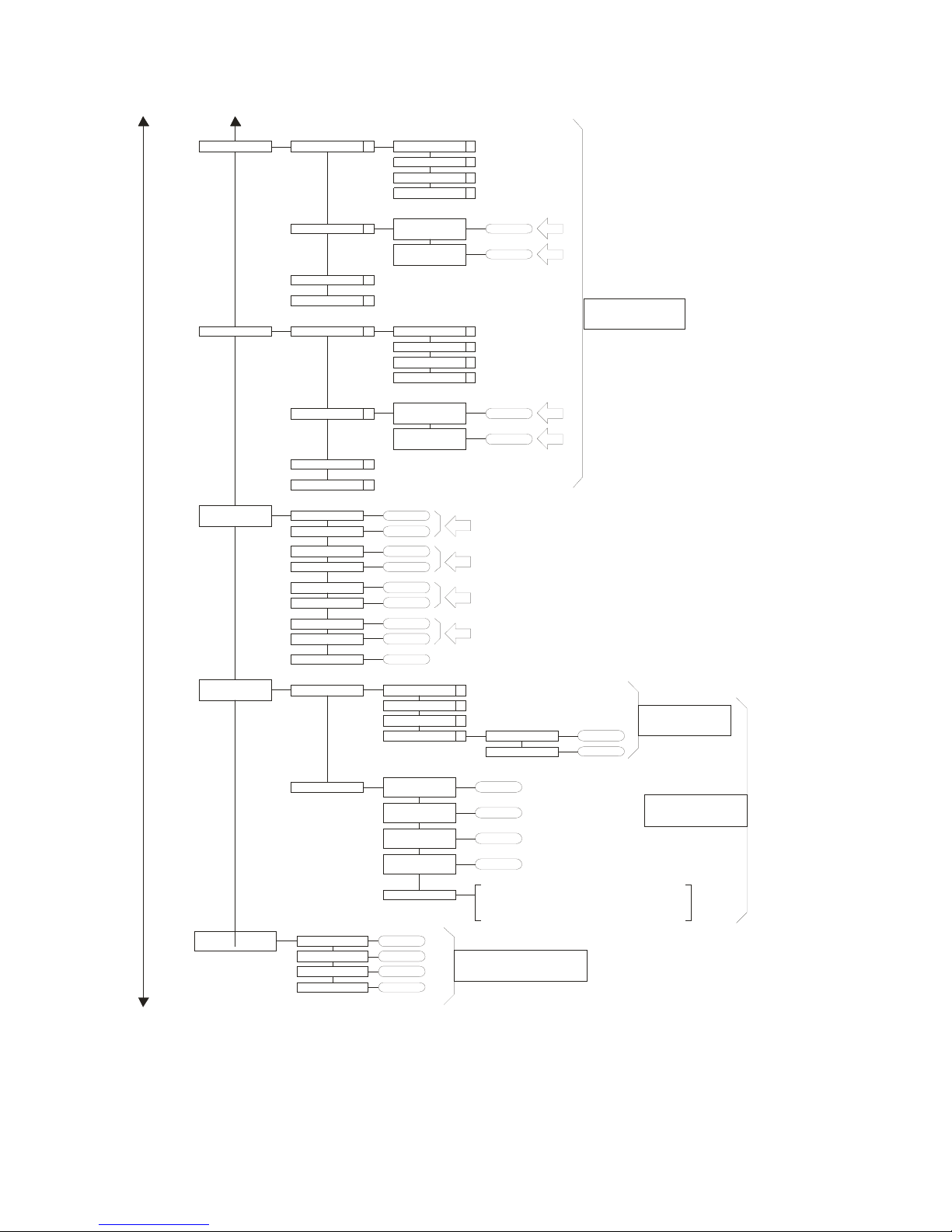
RELAY 1
RELAY 2
ALARM
SETPOINTS
CONTROL
SYS FAIL
LOCAL
CONTROL
SYS FAIL
LOCAL
H I HI AL ARM
HI HI HY S
HI ALARM
HI HYS
LO ALARM
LO HYS
LO LO ALARM
LO LO HYS
TIM EOUT TIME
HI HIALARM
HI
LOW
LOW LOW
ON
SET PO INT
OFF
SET PO INT
HI HIALARM
HI
LOW
LOW LOW
ON
SET PO INT
OFF
SET PO INT
H M
H M
H M
H M
H M
H M
H M
H M
ONLY APPEARS IF
RELAY MODULE
OPTIO N IS INSTALLED
ANALOG
OUTPUT
DIGITAL
COMMUNICATION
CONTROL
ID 1
ID 2
ID 4
ID 4
DEPTHGAU GE
VOLUM E
WEIGHT
SPEC. GRAVITY
MIN
SET PO INT
MIN
CURRENT
MAX
SET PO INT
MAX
CURRENT
MANUAL
ONLY SELECTIONS
THAT ARE ACTIVE
4 mA
20 mA
IN MANUAL MODE 4-20ma OUTPUT IS
MANIPU LATED W I TH UP AND DOWN BUTTONS
AND DISPLAYED 0-100% ON THE DIGITAL DISPLAY
BAR GRAPH REMAINS DEPTH DISPLAY
ONLY APPEARS IF DIGITAL
COMMUNICATION OPTION
IS INSTALLED
WILL APPE AR
OPTIO N IS INSTALLED
ONLY APPEARS IF
ANALOG OUT PUT
©2013 Technical Marine Service, Inc. LC-100 V2.97
Page 99
Page 100
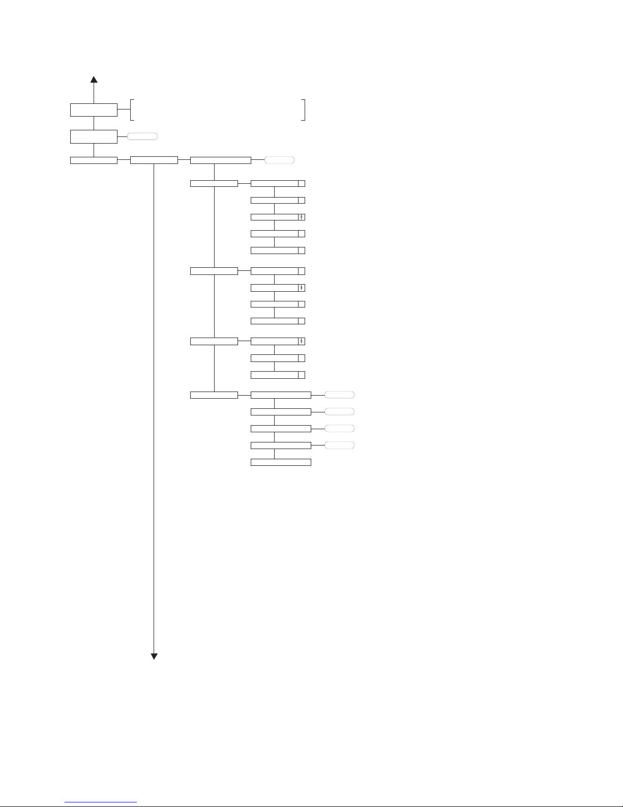
HOT MENU
SETUP
NEW
PASSWOR D
UTILITIES COMM SETUP
ALL ITEMS MARKED AS “HOT MENU SELECTIONS”
AND THAT HAVE BEEN CONFIGURED AS ACTIVE
WILL APPEAR HERE AND CAN BE ADDED T O THE HOT MENU
******
NETWORK ADDR ESS
BAUD RATE
PAR I TY
PROT OC OL
DIAGS
1200
2400
4800
9600
19200
N-8-1
N-8-2
EVEN
ODD
NO CHK
CHK
MODBUS
EVEN T COUNT
EXCEPTION COUNT
MESSAGE COUNT
CRC ERROR COUNT
CLEAR COUNTERS
©2013 Technical Marine Service, Inc. LC-100 V2.97
Page 100
 Loading...