

Page 1

l
OPERATOR’S MANUAL
Level 1® H-1200
Fast Flow Fluid Warmer
With:
H-31, Version B,
Air Detector/Clamp
< H-1200 115V
®
< H-1200 230V
6 2
s
Page 2
l
Level 1® H-1200
Fast Flow Fluid Warmer
With:
H-31, Version B, Air Detector/Clamp
<
H-1200 115 V
<
H-1200 230 V
OPERATOR’S MANUAL
®
P/N 40-6917-51A
s
Page 3

SECTION X • Title
ii
FAST FLOW FLUID WARMER
|
Operator’s ManualH-1200
Page 4

General Information
SECTION X • Title
General Information
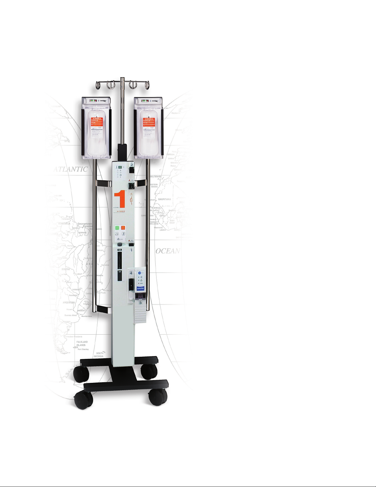
Level 1® H-1200 Fast Flow Fluid Warmer
Part Number: 40-6917-51A
This revision supercedes all previous revisions.
Under copyright laws, this manual may not be reproduced in any form, in
whole, or in part, without prior written permission of Smiths Medical ASD,
Inc. (Smiths Medical).
Smiths Medical and Level 1 design marks and Level 1 are trademarks of
Smiths Medical. The symbol ® indicates the trademark is registered in the U.
S. Patent and Trademark oce and certain other countries. All other names
and marks mentioned are the tradenames, trademarks, or service marks of
their respective owners.
Every eort has been made to ensure that the information in this
manual is accurate and details provided are correct at the time of printing.
The company, however, reserves the right to improve the equipment
shown.
Mention of third-party products is for informational purposes only and
constitutes neither an endorsement nor a recommendation. Smiths Medical
assumes no responsibility with regard to the performance or use of
these products.
For further information, please call your local Smiths Medical distributor or
Smiths Medical direct at 1 800 258 5361 or +1 614 210 7300.
©2014 Smiths Medical.
All rights reserved.
FAST FLOW FLUID WARMER
|
Operator’s ManualH-1200
iii
Page 5

Contents
Contents
1 About this Manual 1
2 Description 3
3 Indications for Use 4
4 Important Safety Information 5
CONTRAINDICATIONS 5
WARNINGS 5
CAUTIONS 8
5 Out of the Box – Assembly 9
Step 1 – Verify Components of the Level 1® H-1200 Fast Flow Fluid Warmer 10
Step 2 – Assemble I.V. Pole to the Warming Unit 11
Step 3 – Install the Pressure Chambers 12
Step 4 – Attach the I.V. Bag Hanger 13
Step 5 – Disinfect the Recirculating Solution Reservoir 13
Step 6 – Preliminary Preparation 14
Step 7 – Connect the Pneumatic Tubing 14
Step 8 – Install the Level 1® H-31, Version B, Air-Detector/Clamp 15
Step 9 – Perform Electrical Safety Tests 17
6 Principle of Operation 19
Fluid Warming 19
Pressurized Fluid Delivery 19
Air Detection/Clamping 19
7 Controls and Displays 20
Fluid Warmer Power and Alarm Test Panel 21
Fluid Warmer Display Panel 22
Reservoir Level Display 22
Pressure Chamber Control Panel 24
Interlocks 25
8 Operation 27
Modes of Operation 28
OFF Mode 28
ON/Automatic Operation Mode for Fluid Warmer 28
Alarm Test Mode 28
Over Temperature Test Mode 29
Temperature Display 29
Check Disposables Mode 29
Add Recirculating Solution Mode 30
Over Temperature Alarm Mode 30
Power ON Test for Air Detector/Clamp 31
Automatic Operation Air Detector/Clamp 31
Check Tubing Mode 31
Air Detected/Clamped Mode 32
Pressure Display 32
Pressurized Mode 32
Unpressurized Mode 32
iv
FAST FLOW FLUID WARMER
|
Operator’s ManualH-1200
Page 6

9 Operating Instructions 33
WARNINGS 34
9.1 Set Up for Use 34
A – Install the Disposable Administration Set 34
B – Prime the Disposable Administration Set 35
C – Prime the Patient Line 37
D – Test the Audible and Visual Alarms 37
E – Test the Air Detector/Clamp 38
9.2 Use of the Fluid Warmer 39
Step 1—Load the Pressure Chambers 40
Step 2—Pressurize the Pressure Chambers 40
Step 3—Make Patient Connection 40
Step 4—Replace the Gas Vent/Filter Assembly 40
Step 5—Change the Fluid Bag 41
9.3 Replace the Gas Vent/Filter Assembly 41
9.4 Activated Alarms 42
9.5 After Use 44
10 Troubleshooting 45
General Troubleshooting Guide 45
Slow Flow Rate Troubleshooting 46
11 Testing 47
Add Recirculating Solution Alarm 47
Check Disposables Alarm 47
Over Temperature Test 48
Fluid Warmer Alarm Signal Test 48
Performance Testing 48
Cold Start Test 48
Calibration Test 49
Calibration Test with DSTA-40 49
Proper Calibration of Recirculating Solution Temperature 49
Periodic Electrical Testing 50
Earth Leakage 50
Ground Continuity 50
12 Maintenance 51
Maintenance Performed Prior to Every Use 51
Clean the Exterior 51
General Inspection 52
Maintenance Performed Every 30 Days 52
Lubricate O-Ring Seals 52
Change Recirculating Solution with Distilled Water 53
Maintenance Performed Every 12 Months 53
Disinfect the Recirculating Solution Reservoir 53
Change Recirculating Solution with a
0.3% Hydrogen Peroxide/Distilled Water Solution 53
Change O-Rings 54
Clean Fan Filter 54
Inspect Air Detector/Clamp 54
Inspect the Reservoir and Float Switch Assembly 54
Testing Fluid Warmer Operation 54
Maintenance and Calibration Log 55
Scheduled Maintenance and Calibration Checklist 55
Contents
FAST FLOW FLUID WARMER
|
Operator’s ManualH-1200
v
Page 7

Contents
13 Limited Warranty 56
14 Service 58
Non-Warranty Work 58
Additional Documentation 58
Disposal Information 58
Service Contacts 59
15 Specications 60
System Specications 61
Standard Compliance 61
Physical 61
Environmental 61
Thermal 61
Electrical 61
Electromagnetic Environment Recommendations 61
Disposable Administration Set Specications 61
DI-50 61
D/DI-60HL 61
D/DI-70 62
D/DI-100 62
D/DI-300 62
16 Symbols 63
Index 66
vi
FAST FLOW FLUID WARMER
|
Operator’s ManualH-1200
Page 8
SECTION 1
SECTION 1 • About this Manual
1 About this Manual
About this Manual
WARNING: These instructions contain important information for safe use
of the product. Read the entire operator’s manual, including Warnings and
Cautions, before using this product. Failure to properly follow warnings,
cautions and instructions could result in death or serious injury to the patient.
This Operator’s Manual describes the set-up, use, and maintenance of:
• Level 1® H-1200 Fast Flow Fluid Warmer
• Level 1® H-1000 Fast Flow Fluid Warmer with H-2 Pressure
Chambers (H-1025)
• Level 1® H-1000 Fast Flow Fluid Warmer with H-2 Pressure
Chambers and H-31, Version B, Air Detector/Clamp
The manual is intended for use by individuals trained in the healthcare
and biomedical professions.
This operator’s manual is also for users of the H-1000 Fast Flow
Fluid Warmer. All references to the “Level 1® H-1200 Fast Flow Fluid
Warmer” apply to the H-1000 Fast Flow Fluid Warmer except where
indicated by the symbols dened in the following table.
Symbol Description
Appears in the margin to identify information that
only applies to the H-1200 Fluid Warmer and the H-1000
Fluid Warmer equipped with the H-31, Version B,
Air Detector/Clamp
Appears in the margin to identify information that only
applies to the H-1000 Fluid Warmer (not equipped with
the H-31, Version B, Air Detector/Clamp)
Conventions Used in this Manual
This manual uses the following text and text conventions:
Convention Description
CONTRAINDICATION
WARNING
CAUTION
A Contraindication statement alerts the user to
conditions when the device should not be used.
A Warning statement alerts the user to conditions that
may cause death or serious injury to the patient or user.
A Caution statement alerts the user to conditions that
may cause malfunction, failure, or damage to the device.
FAST FLOW FLUID WARMER
|
Operator’s ManualH-1200
1
Page 9

SECTION 1 • About this Manual
This manual is organized into the following sections:
2 and 3 Description and Indications for Use
These sections provide the purpose and indications for use of the
Level 1® H-1200 Fast Flow Fluid Warmer.
4 Important Safety Information
Lists the Contraindications, Warnings, and Cautions associated with
the use of the Level 1® H-1200 Fast Flow Fluid Warmer.
5 Out of the Box—Assembly
Guides the user through the installation of the Level 1® H-1200
Fast Flow Fluid Warmer and the Level 1® H-31, Version B,
Air Detector/Clamp.
6 Principle of Operation
Provides a functional description of the Level 1® H-1200 Fast Flow
Fluid Warmer.
7 Controls and Displays
Provides a description of the function and purpose of the
controls, displays, and indicators for the Level 1® H-1200 Fast Flow
Fluid Warmer.
8 Operation
Describes Operation, Indicator, and Alarm modes of the Level 1®
H-1200 Fast Flow Fluid Warmer.
9 Operating Instructions
Describes the Set Up, Use, and Alarm modes of the Level 1® H-1200
Fast Flow Fluid Warmer.
10 Troubleshooting
Contains information on troubleshooting the Level 1® H-1200
Fast Flow Fluid Warmer. This section also details troubleshooting
slow uid ow rates.
11 Testing
Describes Operational, Performance, and Electrical Tests that are
used to verify the proper operation of the Level 1® H-1200 Fast Flow
Fluid Warmer.
12 Maintenance
Regular maintenance procedures for every use, 30-day, and
12-month intervals are covered in this section.
13 Limited Warranty
Describes the Limited Warranty and its provisions.
14 Service
Explains Non-Warranty Work as well as listing Service Contacts.
15 Specications
Provides physical, environmental, and electrical specications of the
Level 1® H-1200 Fast Flow Fluid Warmer.
16 Symbols
Lists the symbols and their denitions used with the Level 1®
H-1200 Fast
Flow Fluid Warmer.
2
FAST FLOW FLUID WARMER
|
Operator’s ManualH-1200
Page 10

SECTION 2
SECTION 2 • Description
2 Description
Description
®
The Level 1
uid warmer with pressure chambers, air detection, and automatic
clamping capability. I.V. uid and/or blood products are warmed
through the use of a sealed heat exchanger through which a
recirculating solution ows. Pressure Chambers apply pressurization
and deliver the uids at a fast ow rate. This non-invasive method
employs single-use, disposable administration sets that include a Gas
Vent/Filter Assembly and Heat Exchanger.
The Air Detector/Clamp monitors for the presence of air in the
disposable Gas Vent/Filter Assembly. When air is detected in the Gas
Vent/Filter Assembly, the Air Detector/Clamp closes o the patient
line and alerts operators to the presence of air with audible and visual
alarms. An ultrasonic signal continually passes through the uid lled
Gas Vent/Filter Assembly. As a bolus of air displaces the uid in the Gas
Vent/Filter Assembly, the ultrasonic signal is broken and the clamp
closes, stopping the air before it enters the patient line. Audible and
visual alarms are activated, notifying the user that the uid ow has
stopped. Clearing the bolus of air and restoring the uid ow are
quickly accomplished without disconnecting from the patient.
H-1200 Fast Flow Fluid Warmer (Fluid Warmer) is an I.V.
Disposable Administration Sets
The installation, set up, and replacement of Level 1® Fast Flow I.V.
Disposable Administration Sets (Disposable Sets) follows a fourstep sequence that corresponds to numbered blocks on the device.
Disposable Sets available for use on the Level 1® H-1200 Fast Flow
Fluid Warmer are listed below.
• DI-50
• D-60 / DI-60HL
• D-70 / DI-70
• D-100 / DI-100
• D-300 / DI-300
D-series Disposable Sets are for use in the U.S.A. DI-series Disposable Sets
are for use in markets outside of the U.S.A.
FAST FLOW FLUID WARMER
|
Operator’s ManualH-1200
3
Page 11

SECTION 3 • Indications for Use
SECTION 3
Indications for Use
The Level 1® H-1200 Fast Flow Fluid Warmer (Fluid Warmer) provides
a rapid ow of warmed uids, such as crystalloid or blood product,
including red blood cells, as volume replacement for patients suering
from blood loss due to trauma or surgery.
The Fluid Warmer provides fast ow of warmed uid to re-warm patients
during surgery by trained medical personnel.
3 Indications for Use
4
FAST FLOW FLUID WARMER
|
Operator’s ManualH-1200
Page 12

SECTION 4 • Important Safety Information
SECTION 4
4 Important Safety Information
CONTRAINDICATIONS
WARNINGS
Important Safety Information
This section covers information for prescribers and guidelines for safe
®
use of the Level 1
Not for use in warming platelets, cryo-precipitates, or
granulocyte suspensions.
Death or serious injury may occur to the patient or user if
these warnings are not followed:
H-1200 Fast Flow Fluid Warmer (Fluid Warmer).
CONTRAINDICATIONS
WARNINGS
• These instructions contain important information for safe use
of the product. Read the entire operator’s manual, including
Warnings and Cautions, before using this product. Failure to
properly follow warnings, cautions, and instructions could result
in death or serious injury to the patient or user.
• Remove all air from the uid bags before spiking and the uid
lines before connecting to the patient. Failure to do so can result
in infusion of air into the patient.
• Replace Gas Vent/Filter Assembly every three hours, or when
the lter becomes clogged, or when air is slowly vented.
Failure to do so will result in a reduction of ow rate. This
may result in inadequate patient treatment
• The replacement Gas Vent/Filter Assembly must be fully
primed before continuing infusion. Failure to do so may
allow air to be infused into the patient.
• Do not use the Fluid Warmer in high-energy elds such as:
MRI, X-RAY, portable and mobile RF communications equipment,
and other such devices. The Fluid Warmer may act as a
projectile in a strong magnetic eld, cause image artifacts, or
not function as intended.
• Do not bend the heat exchanger. Bending may damage the
heat exchanger allowing communication between the
recirculating solution and I.V. uid path, resulting in the I.V.
delivery of inappropriate uids.
FAST FLOW FLUID WARMER
|
Operator’s ManualH-1200
5
Page 13

SECTION 4 • Important Safety Information
WARNINGS [continued]
• Blood and blood products could contain pathogenic
organisms. Failure to follow institutional policy and
procedures for biomedical-hazardous materials could lead to
exposure to harmful pathogens.
• When injecting medications into the uid path, do not inject
through the triple lumen tubing of the D/DI-60HL Disposable
Set. This may allow communication between the recirculating
solution and I.V. uid path.
• Exposed conductor on MAINS power cord can cause an
electrocution hazard. Remove device from service if MAINS
power cord has exposed wires.
• Do not re-use partially full uid bags. Fluid bags that have
been partially drained, un-spiked, and then reinstalled may
contain air, which if used can result in infusion of air into the
patient. Use only new uid bags from which the air has
been removed.
• Activation of the Over Temperature warning signal indicates
that warming has stopped and immediate operator
intervention is required. Failure to clear the over temperature
condition or to take the device out of service may result in death
or serious injury to the patient.
• The Fluid Warmer is not for use with irrigating tubing, which
may not t into the clamp slot of the Air Detector/Clamp
causing diminished ow or a failure to stop ow.
• The Fluid Warmer is for use only with Smiths Medical
supplied or approved parts, accessories, and D or DI series
Disposable Sets. The device may not function as intended with
the use of unapproved parts, accessories, or Disposable Sets.
• Grounding reliability can only be achieved when MAINS
power cords are connected to a properly grounded
receptacle. Risk of electrical shock exists if the equipment is
not connected to a properly grounded receptacle.
• Use of a bedside leukocyte reduction lter may cause a
sudden precipitous drop in blood pressure resulting in
respiratory distress, facial ushing, abdominal pain and
nausea, and loss of consciousness. Immediately stop
transfusion, and follow institution’s protocol for treatment of
transfusion reactions.
• Do not operate the Fluid Warmer in the presence of a ammable
anesthetic mixture with air, oxygen, or nitrous oxide. The risk of
6
FAST FLOW FLUID WARMER
|
Operator’s ManualH-1200
Page 14

SECTION 4 • Important Safety Information
WARNINGS [continued]
explosion exists if the Fluid Warmer is operated in
a potentially explosive environment.
• No user-serviceable parts. All service must be performed by
Smiths Medical or competent personnel.
• Disposable Sets are supplied with a sterile uid path which may
be compromised if the caps are not in place. Do not use
Disposable Set if Luer and spike caps are not securely in place,
or if Luer connections are not secure as the uid path may not
be sterile and may cause death or serious injury to the patient.
• Disposable Sets are for single use only. To reduce the risk of
cross contamination, do not reuse Disposable Sets.
• If uid exits the Patient Line of the D/DI-60HL Disposable Set,
replace the Disposable Set.
• Do not use auto-transfusion bags. Auto-transfusion bags
may contain air that can result in infusion of air into the patient.
• Set-up, priming, and use require aseptic technique. Failure to
use aseptic technique may result in death or serious injury to
the patient.
• Do not use the Fluid Warmer if equipment or Disposable
Set malfunction is evident.
• No modication of this equipment is allowed.
WARNINGS for the Air Detector/Clamp
• The tubing must be properly placed in the Clamp Slot of the
Air Detector/Clamp. Failure to ensure that the tubing is
correctly positioned in the Clamp Slot may result in failure to
stop air infusion.
• Activation of the Air Detector/Clamp alarm during infusion
indicates that uid ow has stopped and that immediate
operator intervention is required to restore uid ow.
Failure to reinstate ow (after purging any air or foam) may
result in death or serious injury to the patient.
• Do not turn OFF the Fluid Warmer when the Air Detector alarm
is active. If the Fluid Warmer is powered OFF in an active alarm
state, the Air Detector/Clamp will open and the Air Detector
will become disabled. This could allow any air within the patient
line to be delivered to the patient resulting in serious injury
or death.
FAST FLOW FLUID WARMER
|
Operator’s ManualH-1200
7
Page 15

SECTION 4 • Important Safety Information
WARNINGS for the Air Detector/Clamp [continued]
• The functional test for the Air Detector/Clamp accessory
must be performed before each use. If any visual indicator
does not illuminate or the audible signal does not sound,
do not use the Fluid Warmer. Remove the device from service
immediately. Fully functional visual and audible alarm systems
are essential for the safe use of the Air Detector/Clamp.
CAUTIONS
Malfunction, failure, or damage to the device may occur if these
cautions are not followed:
• Never use organic solvents (e.g., acetone), strong acids, or
bases to clean any portion of the Fluid Warmer.
• Do not place the Fluid Warmer directly under a faucet or use a
faucet sprayer to rinse. Never spray cleaning or other uids into
openings on the Fluid Warmer or into the external connectors.
CAUTIONS
• When loading uid bags into Pressure Chambers, choose a
hanging hook that allows the bag port to hang freely in the
indented slot at the bottom of the chamber door. If bag ports
are positioned above this slot, diminished ow could occur.
• Federal law (U.S.A.) restricts this device to sale by or on the
order of a physician.
• Medical devices require specic material characteristics to
perform as intended. These characteristics have been veried
for single use only. Any attempt to re-process the device for
subsequent re-use may adversely aect the integrity of the
device or lead to deterioration in performance.
8
FAST FLOW FLUID WARMER
|
Operator’s ManualH-1200
Page 16

SECTION 5
SECTION 5 • Out of the Box—Assembly
5 Out of the Box – Assembly
Out of the Box—Assembly
This device must be assembled and tested by authorized Smiths Medical
personnel, an authorized distributor of Smiths Medical, or competent
personnel prior to placing the device into service.
The following steps describe how to assemble and do preliminary set up
of the Level 1® H-1200 Fast Flow Fluid Warmer (Fluid Warmer).
Refer to Step 8 if you need to install the Level 1® H-31, Version B, Air
Detector/Clamp to the Level 1® H-1000 Fast Flow Fluid Warmer.
Step 1 Verify components of the Fluid Warmer
Step 2 Assemble I.V. Pole to Warming Unit
Step 3 Install Pressure Chambers
Step 4 Attach the I.V. Bag Hanger
Step 5 Disinfect the Recirculating Solution Reservoir
Step 6 Preliminary Preparation
Step 7 Connect the Pneumatic Tubing
Step 8 Install the Level 1® H-31, Version B,
Air Detector/Clamp
Step 9 Perform Electrical Safety Tests
Read through the instructions completely prior to setting up the device.
Note: After unpacking the system, recycle packaging material according to
hospital policy for recyclable materials.
FAST FLOW FLUID WARMER
|
Operator’s ManualH-1200
9
Page 17
SECTION 5 • Out of the Box—Assembly
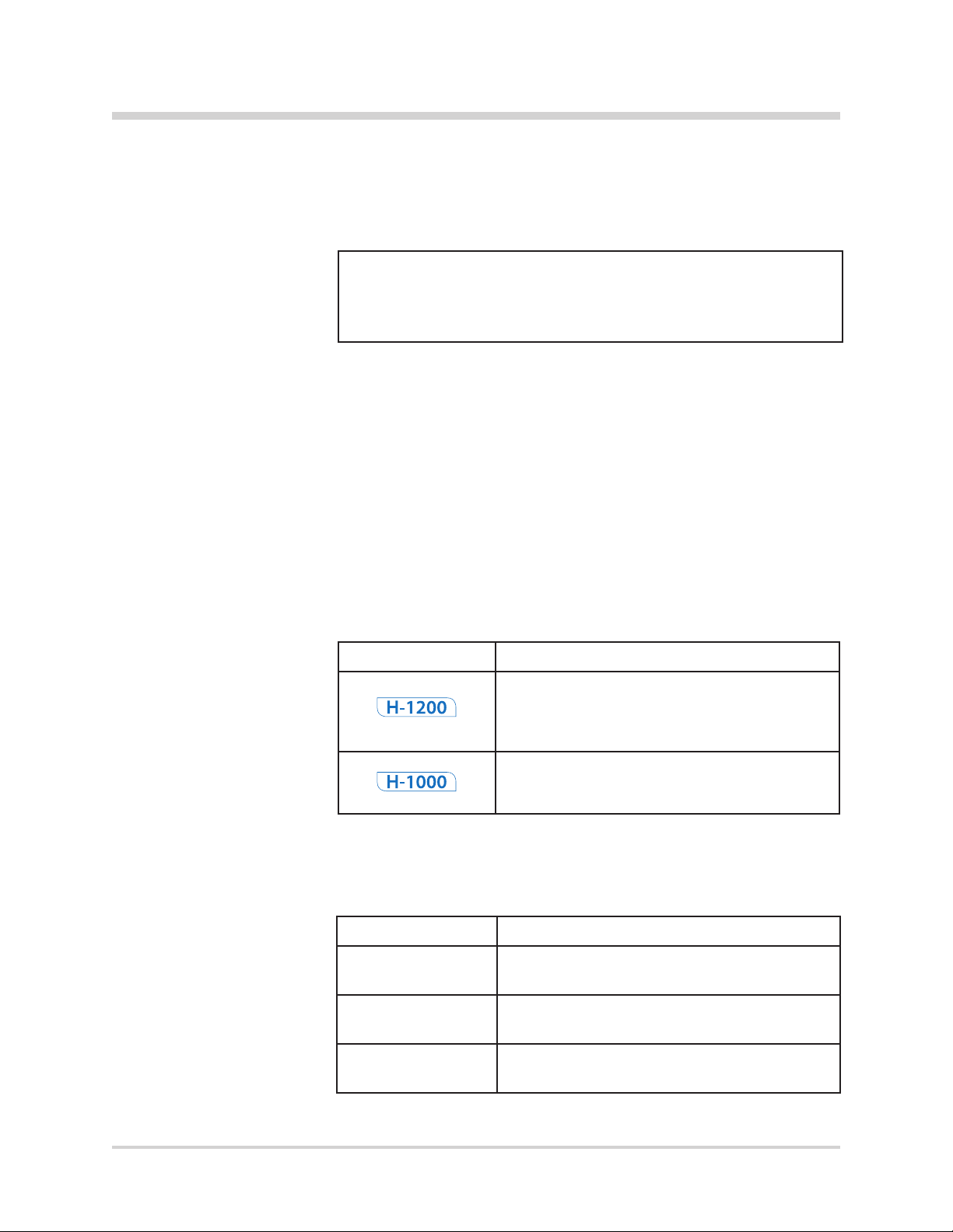
Step 1 – Verify Components of the Level 1® H-1200
Fast Flow Fluid Warmer
Note: The Level 1® H-31, Version B, Air Detector/Clamp is shipped as a
separate accessory only for installation on an existing Level 1® H-1000
Fast Flow Fluid Warmer.
Check the contents of all packaging to verify that the following
components are present. If any parts are missing or damaged, do
not use the Fluid Warmer. Do not substitute parts not supplied by
Smiths Medical. Contact Smiths Medical for replacement parts.
Below is a listing of the component parts for the Level 1® H-1200
Fast Flow Fluid Warmer.
Components Checklist
in order of appearance in illustration
Qty Component
2 Pressure Chambers / Contents:
(2) “U” brackets
(4) Thumbscrews
1 I.V. Bag Hanger
1 Fluid Warming Unit
1 H-31, Version B, Air
Detector/Clamp
1 Accessory Pack
(3) Pan-head screws
(3) Power Cord Clips
(3) Flat-head screws
1 Operator’s Manual
1 Quick Reference Guide
1 I.V. Pole with Flanking Brackets
1 Accessory Pack / Contents:
(2) Plastic “J” Clamps
(1) Y Connector
(1) Black Tubing
(1) Hex Wrench
1 O-Ring Kit / Contents:
(1) Silicone
(2) O-Rings
(1) Hex Wrench
(1) Instructions for Use
3 Bolts
3 Washers
1 I.V. Pole Base
10
FAST FLOW FLUID WARMER
|
Operator’s ManualH-1200
Page 18
SECTION 5 • Out of the Box—Assembly
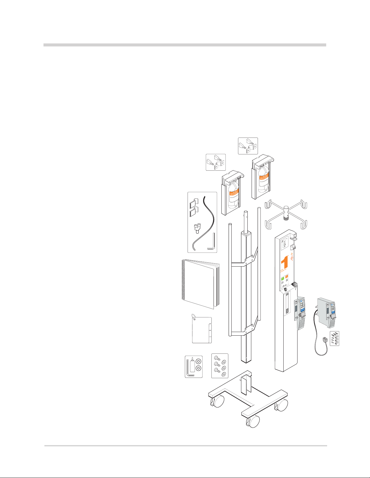
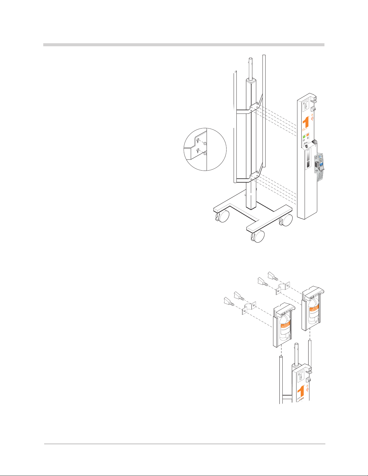
Step 2 – Assemble I.V. Pole to the Warming Unit
There are three steps involved in assembling the I.V. Pole to the
Warming Unit. The steps are: 1. Assemble the I.V. Pole to the Base,
2. Close the Drain Valve, and 3. Attach the Warming Unit to the Flanking
Brackets. Each step is detailed in a short procedure.
2.1 Assemble the I.V. Pole to the Base
1 Locate the I.V. Pole Base (a).
2 Locate the dark-gray extruded I.V. Pole (b) with Flanking
Brackets.
b
d
e
3 Place the I.V. Pole Base upright on its wheels, (c) and lock the
wheels to prevent movement during set up.
4 Locate three bolts (d) and washers for the
pole base.
5 Align the three holes (e) in the I.V. Pole with the three screw
holes on the pole base.
6 Slide the I.V. Pole down over the pole base, (f) keeping holes
f
aligned.
7 Guide three bolts and washers through the holes (g) at the base
of the pole and tighten.
g
c
a
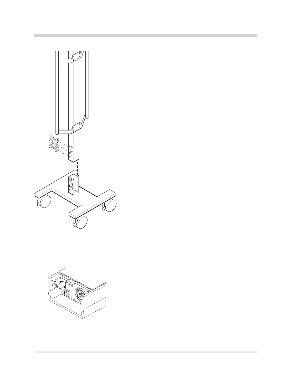
2.2 Close the Drain Valve
h
Turn valve, located on the bottom of the device, perpendicular
to stem (h) of the Warming as shown.
FAST FLOW FLUID WARMER
|
Operator’s ManualH-1200
11
Page 19
SECTION 5 • Out of the Box—Assembly
2.3
Attach the Warming Unit to the Flanking Brackets
1 Align the eight hex screws on the back of the WarmingUnit
with the eight keyhole notches on the anking bracket.
2 Slide screw heads down into keyhole notches.
3 Tighten all eight hex screws with the supplied hexwrench
and secure in place.
Attach the Quick Reference Guide
2.4
to the Fluid Warmer by sliding the ring on the
Quick Reference Guide over one of the poles
on the Flanking Bracket.
Step 3 – Install the Pressure Chambers
1 Locate the two Pressure Chambers.
2 Locate the U-brackets and thumbscrews supplied with
the Pressure Chambers.
3 Attach the U-brackets with thumbscrews to the back of
thePressure Chambers, as shown. Keep thumbscrews
and brackets loose.
4 Slide one Pressure Chamber with attached U-bracket over
the top of each anking pole.
5 Align the U-bracket slightly below the top of the anking
pole. Tighten the thumbscrews securely.
12
FAST FLOW FLUID WARMER
|
Operator’s ManualH-1200
Page 20
MIN
MAX
1
2
SECTION 5 • Out of the Box—Assembly
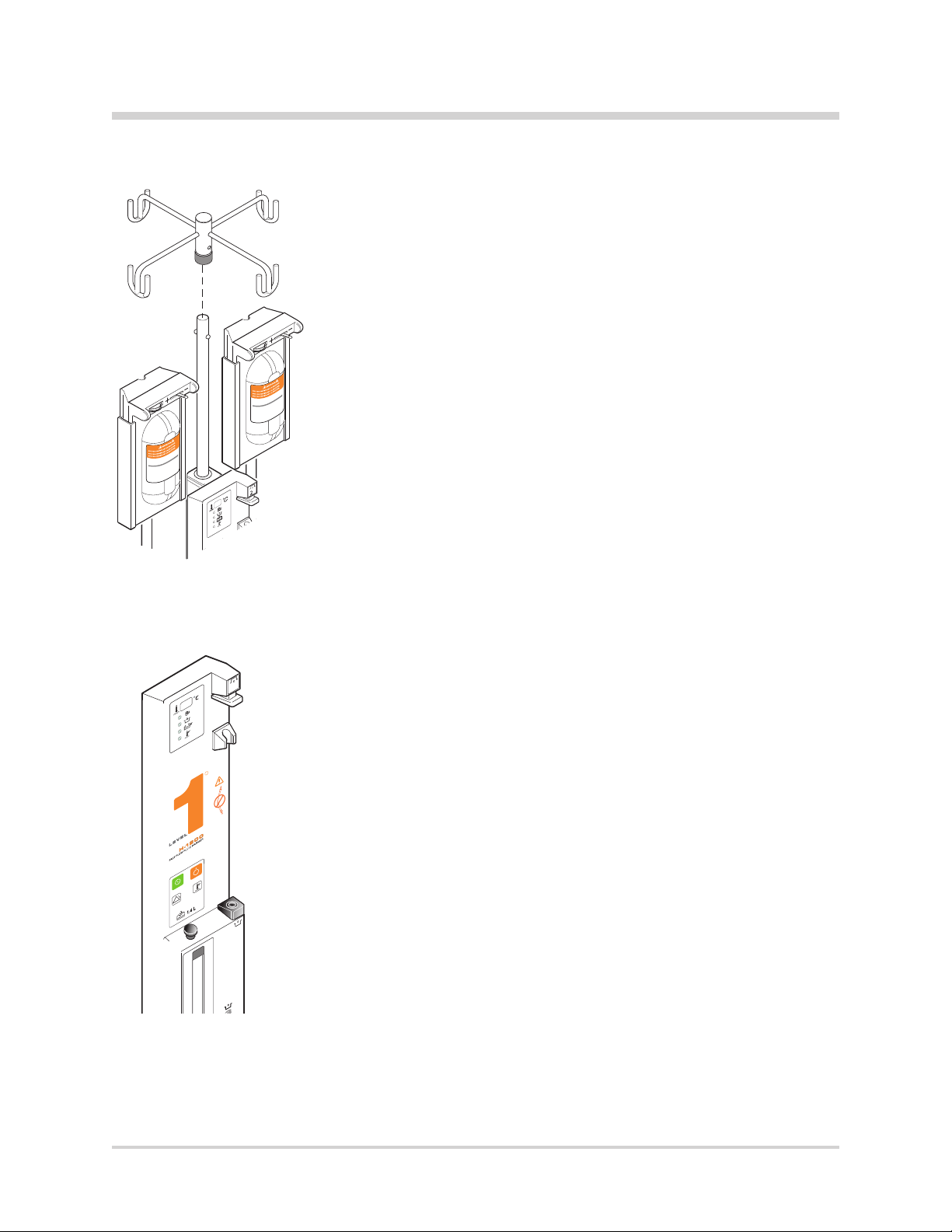
Step 4 – Attach the I.V. Bag Hanger
1 Slide the I.V. Bag Hanger on top of the I.V. Pole.
2 Align with tabs.
3 Press down and snap into place.
Step 5 – Disinfect the Recirculating
Solution Reservoir
1 Remove the ll-port plug (a) on the reservoir.
2
c
R
b
1
a
MAX
2 Prepare a 0.3% hydrogen peroxide/distilled water solution
for the reservoir. Mix 140 ml of 3% hydrogen peroxide
solution and 1,260 ml of distilled water.
3 Fill the reservoir with 1.4 liters of 0.3% hydrogen peroxide/
distilled water solution.
4 Replace the ll-port plug.
5 Insert a Disposable Set into the Fluid Warmer.
6 Insert the power cord into a properly grounded receptacle.
7 Turn the Fluid Warmer ON. Let the solution circulate for a
30-minute disinfection period.
8 Turn the Fluid Warmer OFF.
9 Empty the reservoir.
10 Remove the Disposable Set and discard according to
established hospital procedures.
FAST FLOW FLUID WARMER
|
Operator’s ManualH-1200
13
Page 21
MAX
1
2
SECTION 5 • Out of the Box—Assembly
Step 6 – Preliminary Preparation
1 Remove the ll-port plug (a) on the front of the warming unit
and ll the reservoir to the maximum level with 1.4 liters of one
of the following solutions:
• 0.3% Hydrogen Peroxide/Distilled Water Solution
Mix 140 ml of 3% hydrogen peroxide and 1,260 ml of
distilled water.
Note: If this option is selected, the maintenance requirement to
change the recirculating solution is once every 12 months.
Always use a 0.3% hydrogen peroxide/distilled water solution
when relling the reservoir.
• Distilled Water
Note: If this option is selected, the maintenance requirement to
change the recirculating solution is once every 30 days.
2 Replace the ll port plug.
3 Lubricate O-Rings in #1 Block (b) and #2 Block (c). Place a small
amount of silicone lubricant, provided in the supplied O-Ring
Kit, on a cotton swab and apply all around the inside of each
O-Ring.
c
2
R
b
a
1
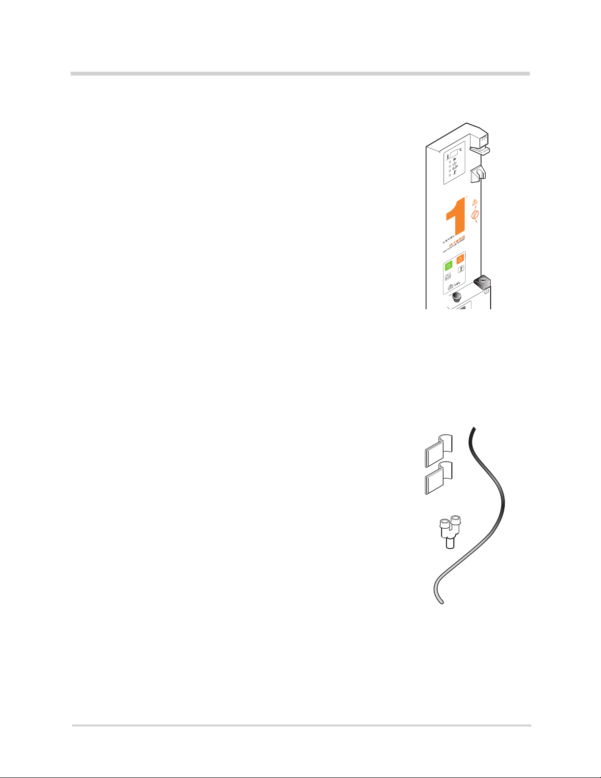
Step 7 – Connect the Pneumatic Tubing
1 Locate the Accessory Pack with the black pneumatic tubing (a),
two “J” clamps (b), and one “Y” Connector (c).
a
b
c
14
FAST FLOW FLUID WARMER
|
Operator’s ManualH-1200
Page 22
SECTION 5 • Out of the Box—Assembly
2 Locate the orange protective plug in the red ring connector (d)
located on the back of the device. Remove the plug by
depressing the red plastic ring as you pull the plug out of the
connector.
f
e
g
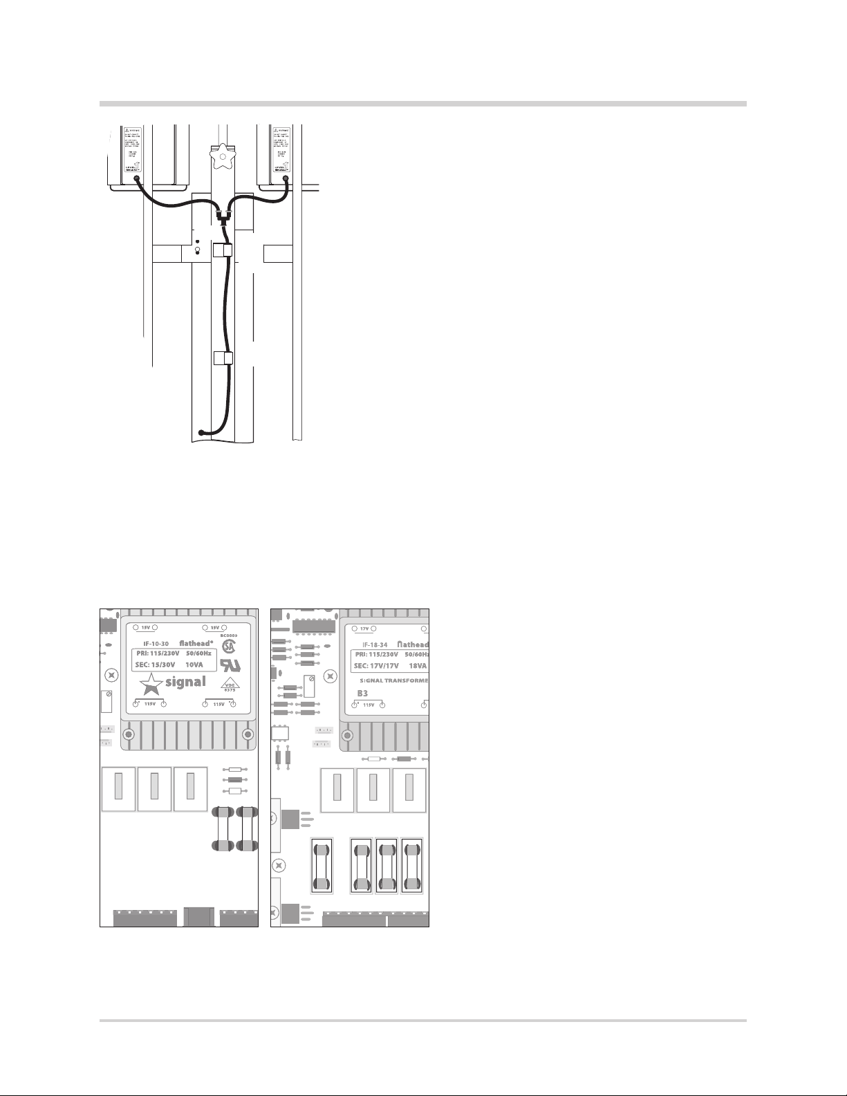
3
Take the pneumatic tubing and press one end of the tubing rmly into
the ring connector
4
Take the “Y” connector and press the other end of the pneumatic
tubing into the bottom of the “Y” connector, as shown
(d)
until it can go no further.
(e)
, until it can
go no further.
5
Press the pneumatic tubing from the Pressure Chamber into place
(f)
on the top of the “Y” connector until it can go no further. Repeat
this procedure with the pneumatic tubing from the other Pressure
h
Chamber.
6
Remove the protective backing sheet on one “J” clamp, exposing the
adhesive side.
7
d
Carefully position the “J” clamp and press the adhesive side against the
gray I.V. Pole in the approximate locations
(g)(h)
shown.
F1
Press down rmly to secure in place.
Repeat this procedure for the other “J” clamp.
8
Press the pneumatic tubing into place on the “J” clamps.
Step 8 – Install the Level 1® H-31, Version B,
Air-Detector/Clamp
Before installing the Air detector, determine if the
Fluid Warmer was manufactured before 2004. If
it is, inspect the “F1” fuse to conrm that it is the
correct value and type. The year of manufacture
can be determined by the serial number label
which is located on the bottom right side of the
unit, or for older units on the inside. If the rst four
characters of the serial number are numbers, then
the numbers represent the year of manufacture (e.g.
20040100 would be manufactured in 2004). If the
rst character of the serial number is the letter “J”,
then the year of manufacture is prior to 2004 (the
letter “S” indicates the year 2007 or later). For units
manufactured prior to 2004, perform the following.
1 Disconnect the power.
Two Fuse Conguration
F1
Four Fuse Conguration
FAST FLOW FLUID WARMER
2 Remove the 18 screws from the rear of the
Fluid Warmer and remove the back panel.
3 Locate the “F1” fuse on the electronic
assembly. See gures to locate the “F1” fuse
for either a two fuse conguration or a four
fuse conguration.
|
Operator’s ManualH-1200
15
Page 23
SECTION 5 • Out of the Box—Assembly
• For 100 - 120V Fluid Warmers,
Remove the fuse and verify that T6.3AL250V (time lag,
6.3 amp, 250V fuse), is printed on one of the silver end
caps, if not replace the fuse with a new fuse marked
T6.3AL250V.
• For 220 - 240V Fluid Warmers,
Remove the fuse and verify that T3.15AL250V (time lag,
3.15 amp, 250V fuse), is printed on one of the silver end
caps, if not replace the fuse with a new fuse marked
T3.15AL250V.
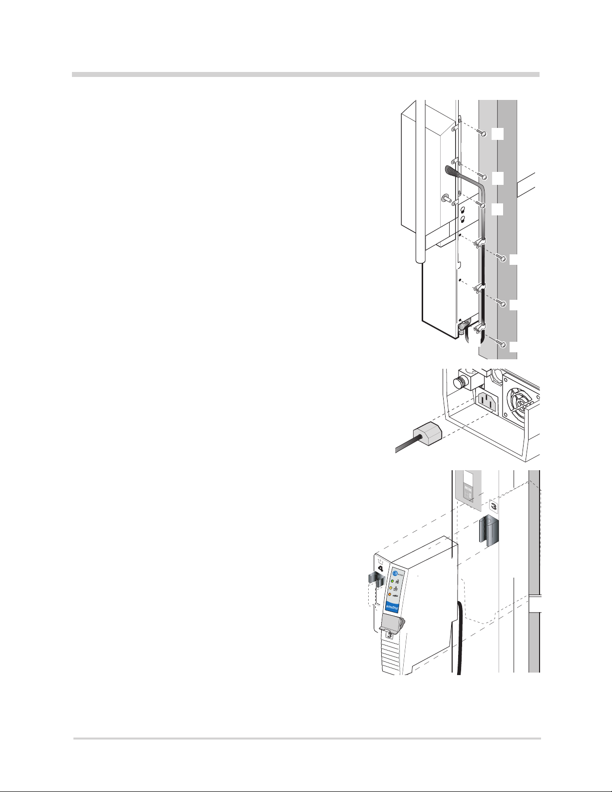
4 Replace the back panel and insert all but 6 of the screws (a)
as indicated in Step 1 below. Then proceed to install the
Air Detector/Clamp.
a
d
a
a
e
a
To install the Air Detector/Clamp,
1 Remove 6 screws (a) from the rear of the Fluid Warmer,
lower left side, from locations shown in gure.
2 Plug in the power cord (b) of the Level 1® H-31, Version B,
Air Detector/Clamp into the auxiliary MAINS outlet located
on the bottom of the Fluid Warmer.
Note: If you turn the Fluid Warmer o and the Air Detector/Clamp
does not turn o, contact Smiths Medical or your local Smiths
Medical distributor.
3 Loosen the three screws holding the mounting bracket to the
rear of the Air Detector/Clamp (do not remove).
4 Align the slot on the Air Detector/Clamp with #3 Block on the
Fluid Warmer (c). Fit in place over the block.
Note: Do not bend the mounting bracket while holding the
Air Detector/Clamp against the uid Warmer.
5 Carefully align the mounting bracket on the rear of the
Air Detector/Clamp with three screw holes, shown (d).
Ensure that the gasket seal on the Air Detector/Clamp is
ush with the Fluid Warmer. Insert three at-head screws
and tighten, securing the Air Detector/Clamp to the
Fluid Warmer. Tighten the three screws on the
mounting bracket on the Air Detector/Clamp.
e
a
e
a
b
c
6 Locate three power cord clips (e) included with the
Air Detector/Clamp and snap onto power cord. Align
clips with the three screw holes as shown, insert
screws, and tighten.
7 Install and prime a Level 1® Fast Flow I.V. Disposable
Administration Set, and test the audible and visual
alarms and Air Detection/Clamp as described in
Section 9 Operating Instructions.
16
FAST FLOW FLUID WARMER
|
Operator’s ManualH-1200
Page 24

SECTION 5 • Out of the Box—Assembly
SECTION X • Title
Step 9 – Perform Electrical Safety Tests
Perform all applicable electrical safety tests as required per
institutional procedure. These include but are not limited to:
• Leakage current • Hypot • Ground bond test
WARNING
Grounding reliability can only be achieved when MAINS power
cords are connected to a properly grounded receptacle. Risk
of electrical shock exists if the equipment is not connected to a
properly grounded receptacle resulting in death or serious
injury to the patient or user.
The Electrical Safety Check must be performed by competent personnel
authorized by the institution to perform such testing. The Safety Check
must be performed and documented at least once per year, or according
to institutional policy.
FAST FLOW FLUID WARMER
|
Operator’s ManualH-1200
17
Page 25

SECTION 6 • Principle of Operation
H-1200H-1200
18
FAST FLOW FLUID WARMER
|
Operator’s ManualH-1200
Page 26

SECTION 6
6 Principle of Operation
Principles of Operation
The schematic illustration on the facing page depicts the Level 1®
H-1200 Fast Flow Fluid Warmer’s (Fluid Warmer) operations. The primary
operations are described below.
Fluid Warming
The Fluid Warmer utilizes a solution reservoir housed in a controller unit.
Recirculating solution is warmed and pumped through a heat exchanger
(a part of the Disposable Set). The solution is returned to the reservoir
for continuous recirculation and remains isolated from the patient and
from the I.V. uid path. The on-board recirculating solution is heated to a
pre-set manufacturer’s temperature set-point. The system continuously
monitors and controls the recirculating solution temperature. The Fluid
Warmer is designed to shut down and provide audible and visual alarms
in the event of an over-temperature condition.
SECTION 6 • Principle of Operation
Pressurized Fluid Delivery
The Fluid Warmer provides pressurized uid delivery through the use
of an on-board compressor and two Pressure Chambers. The Pressure
Chambers pressurize the uid bags for fast uid delivery.
Air Detection/Clamping
The Air Detector/Clamp detects the presence of air in the Gas Vent/Filter
Assembly — a part of the Level 1® D/DI series Disposable Administration
Sets (Disposable Sets) — and clamps the patient line. An ultrasonic signal
continually passes through the uid-lled Gas Vent/Filter Assembly.
As a bolus of air displaces the uid in the Gas Vent/Filter Assembly, the
ultrasonic signal is broken and the clamp closes, stopping the air before it
enters the patient line. Audible and visual alarms are activated, notifying
the user that air has been detected and uid ow has been clamped
o. Clearing the bolus of air and restoring the uid ow are quickly
accomplished without disconnecting from the patient.
FAST FLOW FLUID WARMER
|
Operator’s ManualH-1200
19
Page 27

SECTION 7 • Controls and Displays
WARNING
NOT FOR USE WITH ANY I.V. SOLUTION
CONTAINERS WITH AIR.
REMOVE ALL AIR FROM CONTAINERS
PRIOR TO USE.
NOT FOR USE WITH AUTOTRANSFUSION
BAGS.
Level 1® Pressure Infusion System
Operator Checklist:
1. Spike and hang air-free container.
2. Close door and latch.
3. Squeeze drip chamber ½ to ¾ full and
prime administration set.
4. Move control to +.
CAUTION
When loading uid bags into Pressure
Chambers, choose a hanging hook that
allows the bag port to hang freely in the
indented slot at the bottom of the chamber
door. If bag ports are positioned above this
slot, diminished ow could occur.
4521069 Rev. 009 (06/12)
s
SECTION 7
7 Controls and Displays
Controls and Displays
Five locations on the Level 1® H-1200 Fast Flow Fluid
Warmer (Fluid Warmer) govern how the device is
controlled and where function indicators are displayed.
They are called-out in the gure and are dened in the
list below.
1 Fluid Warmer Display Panel
2 Power and Alarm Test Panel
3 Reservoir Level Display
4 Air Detector/Clamp Control Panel
5 Pressure Chamber Control Panel
The Fluid Warmer has ve Interlocks, which detect for
correct installation of a Disposable Set, that are also dened
this section.
20
FAST FLOW FLUID WARMER
|
Operator’s ManualH-1200
Page 28

SECTION 7 • Controls and Displays
SECTION X • Title
Fluid Warmer Power and Alarm Test Panel
The Power and Alarm Test Panel is located on the front of the Fluid
Warmer directly above the reservoir ll-cap. This panel contains four
pressure-sensitive buttons that are activated when pressed. Refer to the
Power Alarm Test Panel below whose numbered call outs correspond to a
description of the button and the function it performs.
Button/Function
1 Power ON Button
The green button on the top-left of the Power and Alarm Test
Panel powers on the device. Power is applied to the on-board
compressor for the pressure chambers and the Air Detector/
Clamp. The green Automatic Operation LED on the Fluid
Warmer Display Panel illuminates when the Power ON button is
activated, with a Disposable Set in place.
2 Power OFF Button
The Power OFF is the orange button to the right of the Power
ON button on the Power and Alarm Test Panel. This button turns
power o to the unit. The green Automatic Operation LED on
the Display Panel will turn o when this button is pressed.
3 Over Temperature Test Button
The Over Temperature Test is used to conrm the proper
operation of the Over Temperature circuitry. Testing the circuitry
requires that the Fluid Warmer is at operating temperature
(41°C). Once this is established, press and hold the button. Then,
release the button. The Over Temperature alarm continues to
function. Clear the alarm mode by turning the device o, then
back on. See Section 11, Testing, for instruction on performing
an Over Temperature Test.
4 Fluid Warmer Alarm Signal Test Button
The Fluid Warmer Alarm Signal Test is used to conrm proper
operation of the visual and audible alarm indicators. Press and
hold this button to test circuitry. Then, release the button. The
Over Temperature alarm continues to function. Clear the alarm
mode by turning the device o, then back on.
5 Reservoir Capacity
Capacity for recirculating solution reservoir is 1.4 liters. Use
recirculating solution. Do not exceed maximum capacity.
FAST FLOW FLUID WARMER
|
Operator’s ManualH-1200
21
Page 29

SECTION 7 • Controls and Displays
SECTION X • Title
Fluid Warmer Display Panel
The Fluid Warmer Display Panel provides continuous information about
the operation of the Fluid Warmer. A liquid crystal display (LCD)
indicates recirculating solution temperature. Just below the LCD, four
light-emitting diodes (LEDs) indicate operation modes for the device. For
identication purposes, the diodes are shown illuminated.
1 Recirculating Solution Temperature
The temperature of the recirculating solution is displayed in
the LCD panel. The temperature is displayed in degrees Celsius.
Note: This is NOT the temperature of uid delivered to
the patient—the display reects the temperature of the
recirculating solution.
2 Automatic Operation LED
The green LED indicator illuminates when the power is ON and
the Disposable Set has been properly installed. When lit, this
indicates the Fluid Warmer is operating.
3 Check Disposables LED
The yellow LED indicator illuminates and an audible attention
signal beeps when the Disposable Set is not properly installed.
See the Interlocks description in this section for directions on
clearing the Check Disposables alarm.
4 Add Recirculating Solution LED
The yellow LED indicator illuminates and an audible attention
signal beeps when reservoir is low. Additional recirculating
solution must be added to the reservoir. Maximum capacity for
the reservoir is 1.4 liters of recirculating solution.
5 Over Temperature LED
The red LED indicator illuminates and an audible warning signal
beeps when the recirculating solution is over the acceptable
temperature for safe use.
Reservoir Level Display
The Reservoir Level Display has a clear window for viewing the amount
of recirculating solution present in the reservoir. Check the reservoir to
ensure the solution level is near the maximum level indicator (a). If the
recirculating solution level is too low, the Add Recirculating Solution LED
on the Display Panel illuminates and an audible attention signal beeps.
a
22
FAST FLOW FLUID WARMER
|
Operator’s ManualH-1200
Page 30

H-31B
SECTION 7 • Controls and Displays
SECTION X • Title
Air Detector/Clamp Control Panel and Alarms
WARNING
Do not turn OFF the Fluid Warmer when the Air Detector alarm
is active. If the Fluid Warmer is powered OFF in an active alarm
state, the Air Detector/Clamp will open and the Air Detector
will become disabled. This could allow any air within the patient
line to be delivered to the patient resulting in serious injury
or death.
The Air Detector/Clamp Control Panel has three LED indicators
that display the operational state of the Air Detector/Clamp.
Refer to the gure.
1 Automatic Operation LED
The green Automatic Operation LED illuminates when the
following conditions are present: The Fluid Warmer power is ON,
a Disposable Set is properly installed in the Fluid Warmer and
primed, the patient line from the Gas Vent/Filter Assembly is
correctly placed in the #3 Clamp Slot, and the Clamp Slot door
is closed.
2 Check Tubing LED
The yellow Check Tubing LED illuminates and an audible
attention signal beeps when the patient line tubing from the
Gas Vent/Filter Assembly is not correctly placed in the #3 Clamp
slot, and when the Clamp Slot door is not closed correctly.
3 Clamped LED
The red Clamped LED illuminates and an audible warning signal
beeps when air is detected in the Gas Vent/Filter Assembly. The
patient line is automatically clamped.
FAST FLOW FLUID WARMER
|
Operator’s ManualH-1200
23
Page 31

SECTION 7 • Controls and Displays
Pressure Chamber Control Panel
The Pressure Chamber Control Panel uses a control lever to switch
from pressurized to unpressurized mode. A gauge displays pressure
levels in the Pressure Chamber.
1 Pressurize / Unpressurize Lever
This lever is used to control the pressure mode in the
Pressure Chamber.
a To Pressurize the Pressure Chamber
With Pressure Chamber door closed and latched,
slide lever to the left, all the way to the plus (+)
pressurized position. This applies 300 mmHg
pressure in the Pressure Chamber when the Fluid
Warmer is turned ON.
a
b To Unpressurize the Pressure Chamber
To remove pressure from the Pressure Chamber,
slide the lever to the right, all the way over to the
minus (–) unpressurized position. Pressure is
released on the uid bag in the Pressure Chamber.
2 Pressure Gauge
This gauge indicates the pressure present in the
Pressure Chamber. When the Pressurize lever is in the
plus (+) pressurized position and the Fluid Warmer is
ON, this gauge displays the operating pressure in the
Pressure Chamber. The operating pressure should be
300 mmHg.
b
24
FAST FLOW FLUID WARMER
|
Operator’s ManualH-1200
Page 32

SECTION 7 • Controls and Displays
WARNING
NOT FOR USE WITH ANY I.V. SOLUTION
CONTAINERS WITH AIR.
REMOVE ALL AIR FROM CONTAINERS
PRIOR TO USE.
NOT FOR USE WITH AUTOTRANSFUSION
BAGS.
Level 1® Pressure Infusion System
Operator Checklist:
1. Spike and hang air-free container.
2. Close door and latch.
3. Squeeze drip chamber ½ to ¾ full and
prime administration set.
4. Move control to +.
CAUTION
When loading uid bags into Pressure
Chambers, choose a hanging hook that
allows the bag port to hang freely in the
indented slot at the bottom of the chamber
door. If bag ports are positioned above this
slot, diminished ow could occur.
4521069 Rev. 009 (06/12)
s
Interlocks
The Fluid Warmer has ve Interlocks that detect for proper
installation of a Disposable Set’s components. Refer to the
gure to identify the positions of interlocks.
Note: Block 1 is not an Interlock. It cannot detect if a Disposable
Set is not correctly installed. It is identied here because it is
an essential step for proper installation of the Disposable Set
components.
Three Interlocks are located on the Fluid Warmer and check for
proper installation of:
2 Heat Exchanger, top end
4 Gas Vent/Filter Assembly
5 Heat Exchanger (guide)
Two Interlocks are located in the Air Detector/Clamp 3 and
check for the proper installation of:
Patient I.V. Line in the Clamp Slot
Door for the Clamp Slot
Interlocks 2, 4, and 5 prevent the Fluid Warmer’s pump from
circulating reservoir solution if the Disposable Set’s Heat
Exchanger and Gas Vent/Filter Assembly are not installed
properly.
If Check Disposable Alarm is Activated on the Fluid Warmer
a Check Heat Exchanger for proper installation in Block 1,
and Interlocks 2 and 5.
b Press Heat Exchanger down rmly in Block 1 to secure
in O-Ring.
c Press Interlock 2 tab down rmly to engage the
Interlock switch.
d Press Heat Exchanger rmly into Interlock 5.
e Check Gas Vent/Filter Assembly installation in
Interlock 4.
If Check Tubing Alarm is Activated on the
Air Detector/Clamp
a Open the door and check the Patient Line for proper
installation in the Clamp Slot at interlock 3.
b Close the door and check that the tab on the top
edge of the door is fully inserted into the Air Detector/
Clamp at interlock 3 before pushing the door down to
close it.
FAST FLOW FLUID WARMER
|
Operator’s ManualH-1200
25
Page 33

SECTION 8 • Operation
Operation
Level 1® H-1200 Fast Flow Fluid Warmer
Function Interface # Description Indicator/Alarm Signal
Fluid
Warmer
Power and
Alarm Test
Panel
Fluid
Warming
Fluid
Warmer
Display
Panel
Visible Audible Beep
1 OFF None None
2 ON LEDs display None
3 Alarm Test LEDs display 1/second
4 Over Temperature
Alarm Test
5 Temperature Display LCD
6 Automatic
Operation
7 Check Disposables Yellow LED:
8 Add Recirculating
Solution
9 Over Temperature Red LED:
LEDs display 1/second
None
Readout
Green LED None
1/5 seconds 62db
Medium
Priority Alarm
Yellow LED:
Medium
Priority Alarm
High
Priority Alarm
1/5 seconds 63db
1/second 65db
26
Air
Air
Detection/
Clamping
Pressurized
Fluid
Delivery
FAST FLOW FLUID WARMER
Detection/
Clamp
Alarm and
Control
Panel
Pressure
Chamber
Control
Panel
10 Automatic
Operation for
Air Detection
11 Check Tubing/
Patient Line
12 Air Detected/
Clamped
13 Pressure Gauge Numbered Dial None
14 Pressurized + Symbol None
15 Unpressurized - Symbol None
|
Operator’s ManualH-1200
Green LED None
Yellow LED:
Medium
Priority Alarm
Red LED:
High
Priority Alarm
1/5 seconds 70db
1/second 75db
Page 34

SECTION 8
SECTION 8 • Operation
8 Operation
Operation
The Level 1
three primary functions; Fluid Warming, Air Detection/Clamping, and
Pressurized Fluid Delivery. Functions are monitored and controlled by
four interfaces/control panels located on the Fluid Warmer.
The four interfaces are:
• Fluid Warmer Power and Alarm Test Panel
• Fluid Warmer Display Panel
• Air Detector/Clamp Alarm and Control Panel
• Pressure Chamber Control Panel
In the table on the facing page, operation of the device is represented
in terms of the four interfaces that control specic device functions.
The numbers call-out individual Modes of Operation activated or
indicated on the interface.
Functions
• Fluid Warming
• Air Detection/Clamping
• Pressurized Fluid Delivery
®
H-1200 Fast Flow Fluid Warmer (Fluid Warmer) performs
Operational modes
• OFF Mode
• ON/Automatic Operation for Fluid Warmer
• Alarm Test Mode
• Over Temperature Test Mode
• Check Disposables Mode
• Add Recirculating Solution Mode
• Over Temperature Alarm Mode
• Power ON Test for Air Detector/Clamp
• Automatic Operation Air Detector/Clamp
• Check Tubing Mode
• Air Detected/Clamped Mode
• Pressurized Mode
• Unpressurized Mode
The modes of operation are individually dened in the following section.
This includes a description of each mode, activation and/or monitoring of
the mode, mode characteristics, and clearing of the mode state.
FAST FLOW FLUID WARMER
|
Operator’s ManualH-1200
27
Page 35

SECTION 8 • Operation
Modes of Operation
WARNING
If any visual indicator does not illuminate or the audible signal
does not sound, do not use the Fluid Warmer. Remove the device
from service immediately. Death or serious injury may occur to the
patient or user if this warning is not followed.
OFF Mode
Power is o only for a part of the equipment. The MAINS are still
connected. Press the OFF button (a) on the Power and Control Panel to
turn the device o.
ON/Automatic Operation Mode for Fluid Warmer
The Fluid Warmer enters Automatic Operating mode when a Disposable
Set is properly installed and the device is turned ON. This is done by
pressing the ON button (b).
a
b
Mode characteristics
• The green Automatic Operating LED on the Display Panel
illuminates (c).
• Fluid warming begins.
• Pressure infusion is provided by activating the Pressure Chambers.
• Air Detector/Clamp enters the Power ON Test, then enters default
Automatic Operation mode.
Alarm Test Mode
The Alarm Test mode is used to test the visual and audible indicators of
the Level 1® H-1200 Fast Flow Fluid Warmer. This mode is entered by
pressing and holding the Alarm Test button (d) on the Fluid Warmer’s
Control Panel.
Mode characteristics
• All visual indicators on the Fluid Warmer’s Display Panel
(e) illuminate.
• The Fluid Warmer’s audible alarm beeps.
• When the Alarm Test button is released, the Over Temperature
LED and an audible alarm remains active.
• To clear the Over Temperature alarm, turn the Fluid Warmer OFF
and then back ON.
c
d
e
28
FAST FLOW FLUID WARMER
|
Operator’s ManualH-1200
Page 36

SECTION 8 • Operation
Over Temperature Test Mode
The Over Temperature Test mode is used to test the operation of the Fluid
f
g
Warmer’s Over Temperature Circuitry. This mode is entered by pressing
and holding the Over Temperature Test button (f) on the Fluid Warmer
Control Panel with the Fluid Warmer at operating temperature (41°C).
Mode characteristics
• The red Over Temperature LED (g) on the Display Panel
illuminates.
• An audible warning signal beeps.
To Clear this mode
• Turn Fluid Warmer OFF.
• Turn Fluid Warmer back ON.
Temperature Display
The Temperature Display functions when the Fluid Warmer is powered
ON. Temperature is displayed in degrees Celsius.
Check Disposables Mode
The Check Disposables mode of the Fluid Warmer indicates a missing or
improperly installed Disposable Set.
Mode characteristics
a
• The Check Disposables yellow LED (a) on the Fluid Warmer’s
Display Panel is illuminated.
• An audible attention signal beeps.
• Reservoir solution circulation is stopped; uid warming stops.
• Pressure Chambers continue to operate.
To Clear this mode
Install a disposable or check the disposable installation as follows:
• Check the position of the disposable in the #1 Block.
• Make sure the heat exchanger is seated in the heat
exchanger guide.
• Press down rmly on the #2 Block.
• Check the position of the Gas Vent/Filter Assembly in the
#4 Interlock.
FAST FLOW FLUID WARMER
|
Operator’s ManualH-1200
29
Page 37

SECTION 8 • Operation
Add Recirculating Solution Mode
The Add Recirculating Solution mode of the Fluid Warmer indicates
that the solution level in the recirculating solution reservoir is below its
minimum level.
Mode characteristics
• The yellow Add Recirculating Solution LED (b), on the Fluid
Warmer’s Display Panel, is illuminated
• An audible warning signal beeps.
• Solution circulation stops, uid warming stops.
• Pressure Chambers continue to operate.
• Fluid ow to the patient continues.
To Clear this mode
Add recirculating solution to the Fluid Warmer’s reservoir.
Over Temperature Alarm Mode
The Over Temperature Alarm mode is entered when the temperature of
the recirculating solution reservoir is at or above 43.9°C
b
WARNING
Activation of the Over Temperature warning signal indicates that
warming has stopped and immediate operator intervention is
required. Failure to clear the over temperature condition or to
take the device out of service may result in patient death or
serious injury.
Mode characteristics
• The Over-Temperature LED warning light illuminates (c).
• An audible warning signal beeps.
• Solution circulation is stopped; uid warming stops.
• Pressure Chambers continue to operate.
• Fluid ow to the patient continues.
To Clear Over Temperature Alarm mode
Do the following:
• If connected to a patient, close all clamps.
• Turn OFF the Fluid Warmer to clear the alarm.
• Turn the power back ON.
• If the Fluid Warmer continues to alarm, remove from service.
Contact Smiths Medical or your local Smiths Medical distributor.
c
30
FAST FLOW FLUID WARMER
|
Operator’s ManualH-1200
Page 38

H-31B
SECTION 8 • Operation
Power ON Test for Air Detector/Clamp
The Power ON Test for the Air Detector/Clamp is activated when the
Fluid Warmer is turned ON. This test activates the Air Detector/Clamp’s
visual and audible indicators.
Mode characteristics
• Audible alarm indicator beeps.
• All LED indicators on the Air Detector/ Clamp Control
Panel illuminate:
1 Automatic Operation LED indicator - Green
2 Check Tubing LED indicator - Yellow
3 Clamped LED indicator - Red
At the end of the Power ON Test the Air Detector/Clamp enters Automatic
Operation mode. This is the default mode for the Air Detector/Clamp.
Automatic Operation Air Detector/Clamp
In Automatic Operating mode, the Air Detector/Clamp monitors for the
presence of air in the Disposable Set’s Gas Vent/Filter Assembly.
If air is detected the patient line is clamped o and an audible alarm
beeps. The Air Detector/Clamp goes into Automatic Operation mode
when the Fluid Warmer is turned ON and Disposable Set is properly
installed and primed—no air is present in the Gas Vent/Filter Assembly.
Mode characteristics
• The green Automatic Operation LED (1) is illuminated.
• Monitoring for air in the Gas Vent/Filter Assembly is active.
• Fluid is ready to be delivered to the patient when in Automatic
Operating mode.
Check Tubing Mode
The Air Detector/Clamp’s Check Tubing mode is entered when the
patient line from the Gas Vent/Filter Assembly is not properly installed in
the Air Detector/Clamp Slot and when the Clamp Slot door is not closed
correctly.
Mode characteristics
• The yellow Check Tubing LED (b) on the Air Detector/Clamp
b
Control Panel is illuminated.
• An audible low-priority warning signal beeps.
To Clear this mode
• Place the patient line from the Gas Vent/Filter Assembly in the
#3 Clamp Slot of the Air Detector/Clamp and close the Clamp
Slot door.
FAST FLOW FLUID WARMER
|
Operator’s ManualH-1200
31
Page 39

SECTION 8 • Operation
Air Detected/Clamped Mode
In this mode the Air Detector/Clamp is activated when the ultrasonic
sensor detects the presence of air in the Gas Vent/Filter Assembly.
Auditory and visual warnings are activated and the clamp is closed,
preventing passage of uid through the patient line.
Mode characteristics
• The patient line is clamped until alarm condition is removed.
• The red Clamped warning indicator LED (c) illuminates.
• The Air Detector/Clamp warning signal beeps.
To Clear this mode
Perform the steps in Section 9, Operating Instructions, under the
heading: Clear the “Air Detected” Alarm mode.
Pressure Display
The Pressure Display gauge (a) functions when the device is ON. The
graduated indicator represents the level of pressure applied to the
uid bags. Pressure should be in the range of 280-300 mmHg pressure.
c
a
Pressurized Mode
The H-2 Pressure Chambers deliver uids at an increased ow rate with
the application of 300 mmHg pressure upon the uid bags. Flow rate
varies according to uid type and viscosity, temperature, Disposable Set
used, and the amount of clamping applied to the roller clamps.
Pressurized infusion is enabled when:
• A uid bag is installed in the Pressure Chamber.
• The Fluid Warmer is turned ON.
• The Pressure Chamber switch is placed in the plus (+)
pressurized position (b).
Mode characteristics
• The Fluid Warmer must be ON for the Pressure Chamber to work.
• Operating pressure should be between 280-300 mmHg.
• Pressure is not adjustable on the Pressure Chamber.
• Pressure is applied to the uid bag in the Pressure Chamber.
• Pressure is indicated on the pressure gauge.
To Exit this mode
• Place the Pressure Chamber switch in the minus (–) unpressurized
position (c).
b
Unpressurized Mode
Disable pressurization by moving the switch on the Pressure
Chamber to the minus (–) unpressurized position (c).
Mode characteristics
• Pressure is released from the Pressure Chamber.
• A uid bag can be removed or loaded into the Pressure Chamber.
32
FAST FLOW FLUID WARMER
|
Operator’s ManualH-1200
c
Page 40

SECTION 9 • Operating Instructions
SECTION 9
9 Operating Instructions
Operating Instructions
The Operating Instructions are grouped into ve segments. Read through
each section BEFORE performing a procedure.
• The Fluid Warmer is for use only with Smiths Medical
supplied or approved parts, accessories, and D or DI series
Disposable Sets. The device may not function as intended with
the use of unapproved parts, accessories, or Disposable Sets
resulting in death or serious injury to the patient or user.
• When injecting medications into the uid path, do not inject
through the triple-lumen tubing of the Level 1® D/DI-60HL
Disposable Set. This may allow communication between the
recirculating solution path and I.V. uid path, which could result
in death or serious injury to the patient.
WARNINGS
• Replace Gas Vent/Filter Assembly every three hours,
or when the lter becomes clogged, or when air is slowly vented.
Failure to do so will result in a reduction of ow rate. This may
result in inadequate patient treatment resulting in death or
serious injury to the patient.
• The replacement Gas Vent/Filter Assembly must be fully primed
before continuing infusion. Failure to do so may allow air to be
infused into the patient resulting in death or serious injury
to the patient.
• Grounding reliability can only be achieved when MAINS power
cords are connected to a properly grounded receptacle. Risk of
electrical shock exists if the equipment is not connected to a
properly grounded receptacle resulting in death or serious injury
to the patient or user.
• Do not bend the heat exchanger. Bending may damage the heat
exchanger allowing communication between the recirculating
solution path and I.V. uid path, resulting in the I.V. delivery of
inappropriate uids which could result in death or serious injury
to the patient.
• The tubing must be properly placed in the Clamp Slot of the Air
Detector/Clamp. Failure to ensure that the tubing is correctly
positioned in the Clamp Slot may result in failure to stop air
infusion which may result in patient death or serious injury.
FAST FLOW FLUID WARMER
|
Operator’s ManualH-1200
33
Page 41

SECTION 9 • Operating Instructions
9.1 Set Up for Use
WARNINGS
• Read and follow all instructions, labeling, and accompanying
documents supplied with this medical device. Failure to follow
instructions, including all warnings and cautions, could result in
death or serious injury to the patient or user.
• Disposable Sets are supplied with a sterile uid path which
may be compromised if the caps are not in place. Do not use
Disposable Set if Luer and spike caps are not securely in place, or
if Luer connections are not secure as the uid path may not be
sterile and may cause death or serious injury to the patient.
• Disposable Sets are for single use only. To reduce the risk of cross
contamination, do not reuse Disposable Sets, which could result
in death or serious injury to the patient.
WARNINGS
A – Install the Disposable Administration Set
The installation sequence for the Disposable Administration Set
corresponds to the numbered Blocks marked 1-2-3-4 on the H-1200 Fast
Flow Fluid Warmer Fluid Warmer) and 1-2-3 on the H-1000 Fluid Warmer.
Remove the Disposable Set from its packaging and review the
Instructions for Use provided. Do not remove spike caps or Luer caps at
this time.
Note: Inspect the Disposable Set prior to use and conrm Luer connections
are secure.
1 Push the bottom end of the Heat Exchanger (a) [the end near
the Gas Vent/Filter Assembly] into #1 Block (b). Press the Heat
Exchanger down rmly to properly seat in the block.
Note: D/DI-60HL Disposable Sets require the Heat Exchanger to be
placed with the Patient Line extending to the left.
2 Slide #2 Block up (c). Snap Heat Exchanger into guide (d). Press
rmly into place to ensure it is properly seated. Slide #2 Block
down (e), push down rmly to secure.
34
a
a
b
FAST FLOW FLUID WARMER
c
d
|
Operator’s ManualH-1200
e
Page 42

H-31B
H-31B
H-31B
H-31B
H-31B
H-31B
H-31B
H-31B
H-31B
H-31B
H-31B
H-31B
H-31B
H-31B
H-31B
H-31B
H-31B
H-31B
H-31B
H-31B
H-31B
H-31B
H-31B
H-31B
H-31B
H-31B
H-31B
H-31B
H-31B
H-31B
H-31B
H-31B
H-31B
SECTION 9 • Operating Instructions
3 Move the pinch clamp on the Patient Line of the Gas Vent/Filter
Assembly next to the Luer connector. Close the pinch clamp.
4 Install the Gas Vent/Filter Assembly.
a Align the Gas Vent/Filter Assembly to the #3 Block,
and press it into place.
b Press the green Power ON button, located on the
Power and Alarm Test Panel, to turn ON the
Fluid Warmer.
5 Install the Gas Vent/Filter Assembly. Refer to the series
of gures.
a Open the #3 Clamp Slot door by pushing down on tab,
(a) and lifting up the front of the door (b).
b
b Pull the door down (c) and away from the Clamp Slot.
c Insert the Patient Line in the Clamp Slot (d) and push
a
it back into the slot.
d Hold the Patient Line in the Clamp Slot and push the
door up (e) to engage the top hinge. Then push the
front of the door down to close it.
e Pull the Patient Line to the right (f) to align it in the
Clamp Slot without kinking.
c
f Align the Gas Vent/Filter Assembly to the #4 Block, (g)
and press it into place.
d
e f
g
B – Prime the Disposable Administration Set
1 Close the Disposable Set clamps above the Heat Exchanger.
• For DI-50, D/DI-60HL, D/DI-70 Disposable Sets,
– close pinch clamps below the bag spikes, and
– close roller clamp below the drip chamber (a).
• For D/DI-100, D/DI-300 Disposable Sets
– close pinch clamps below the drip chambers.
2 Remove all air from the uid bag:
a Invert solution bag.
b Use aseptic technique. Pierce membrane of bag port
a
with spike of Disposable Set. Then withdraw spike.
c Squeeze bag to exhaust ALL air.
d Place spike in bag port. Do not allow air to
re-enter bag.
e Repeat this step for each uid line to be used.
FAST FLOW FLUID WARMER
|
Operator’s ManualH-1200
35
Page 43

SECTION 9 • Operating Instructions
3 Slide lever on H-2 Pressure Chamber to the minus (–)
unpressurized position.
4 Hang spiked uid bag/s in Pressure Chamber:
a Release hinged latch, open door and hang uid bag
inside on tab appropriate for bag size.
b Close the door and secure latch.
c Injection and Spike ports on the uid bag should
extend from opening at the bottom of the Pressure
Chambers without being obstructed.
Note: When installing Level 1® D/DI-300 series Disposable Sets,
hang the third uid bag from the I.V. pole.
CAUTION
When loading uid bags into H-2 Pressure Chambers,
choose a hanging hook that allows the bag port to hang
freely in the indented slot at the bottom of the chamber
door. If bag ports are positioned above this slot, diminished
ow could occur resulting in physical injury to the patient, user,
and/or an adverse eect on the device or its performance.
5 Open clamp above Drip Chamber on Level 1® DI-50, D/DI-60HL,
and D/DI-70 Disposable Administration Sets for each I.V. uid
bag being used to prime the drip chamber.
6 Prime Drip Chamber by squeezing drip chamber until one-half
to three-quarters full of uid.
Note:
drip chamber.
• D/DI-100 and D/DI-300 series use a separate drip
chamber for each spiked bag. The clamp is
below the drip chamber.
7 Open remaining clamps above the Heat Exchanger. Fluid ows
into the Gas Vent/Filter Assembly.
8 Vigorously tap the Gas Vent/Filter Assembly to dislodge
air bubbles from lter screen.
9 Press the green Power ON button, located on the Power and
Alarm Test Panel, to turn ON the Fluid Warmer.
• DI-50, D/DI-60HL, D/DI-70 series use a single
• The Air Detector/Clamp runs a Power ON Test.
• All Air Detector/Clamp indicator LEDs illuminate.
• The audible warning beeps.
– If the above does not occur, remove the device from service.
• Upon completion of the Power On Test the Air Detector/
Clamp enters Operation mode with the Automatic Operation
LED illuminated.
36
FAST FLOW FLUID WARMER
|
Operator’s ManualH-1200
Page 44

SECTION 9 • Operating Instructions
• If the Disposable Set is incorrectly installed, the Fluid
Warmer’s Check Disposables attention indicator illuminates
and the audible attention signal beeps. Check the installation
of the Disposable Set following the directions provided in
Section 6, Controls and Displays, on Interlocks.
C – Prime the Patient Line
1 Remove the male Luer cap from the distal end of the
Patient Line.
Note: On Level 1® D/DI-60HL Disposable Administration Sets
(D/DI-60 HL Disposable Sets), verify that no recirculating
solution comes out of the distal end of the Patient Line.
WARNING
If uid exits the Patient Line of the D/DI-60HL Disposable Set,
replace the Disposable Set.
2 Open the pinch clamp below the Gas Vent/Filter Assembly.
3 Allow uid to ow until no air is observed in the Patient Line and
the line is primed with uid. Then, close the roller clamp on the
Patient Line.
Note: On D/DI-60HL Disposable Sets close roller clamp below
Drip Chamber.
D – Test the Audible and Visual Alarms
Test the visual and audible alarm signals by performing the
following steps.
1 Press and hold the Alarm Test button on the Fluid Warmer’s
Power and Alarm Test Panel.
• All Fluid Warmer visual alarm LEDs illuminate
and the audible alarm signal beeps.
2 Release the Alarm Test button; the Over Temperature
alarm continues.
3 Clear the Over Temperature alarm condition.
• Turn the Fluid Warmer OFF, then ON.
• The Air Detector/Clamp runs a Power On Test.
• The Air Detector/Clamp goes into Automatic operation.
FAST FLOW FLUID WARMER
|
Operator’s ManualH-1200
37
Page 45

SECTION 9 • Operating Instructions
E – Test the Air Detector/Clamp
WARNING
The functional test for the Air Detector/Clamp accessory must be
performed before each use. If any visual indicator does not
illuminate or the audible signal does not sound, do not use the
Fluid Warmer. Remove the device from service immediately. Fully
functional visual and audible alarm systems are essential for the
safe use of the Air Detector/Clamp.
1 Slide the lever on the Pressure Chambers to the plus (+)
pressurized position to pressurize uid delivery.
2 Move the top of the Gas Vent/Filter Assembly away from the
Air Detector sensor as shown.
3 The following occurs:
• The Air Detector clamp closes.
• The red Clamped indicator LED illuminates.
• The audible warning signal beeps.
• Fluid Warmer disposable alarm activates.
If any of the above does not occur, remove the device
from service.
4 Open the roller clamp on the Patient Line to verify that uid
does not ow. After verifying that no uid is owing, close the
roller clamp completely. If uid ow is observed, remove the
device from service.
5 Return to normal operation by pressing the top of the Gas
Vent/Filter Assembly back into the #4 Block.
6 The Air Detector/Clamp resumes Automatic Operation mode.
• The green Automatic Operation LED on the
Air Detector/Clamp Control Panel illuminates.
7 The Fluid Warmer is now ready for patient connection. Unclamp
Patient Line to begin infusion.
Note: On D/DI-60HL Disposable Sets open roller clamp below
drip chamber.
Conclusion
This concludes Section 9.1, Set Up for Use. Operators can proceed to the
next Section 9.2, Use of the Fluid Warmer.
38
FAST FLOW FLUID WARMER
|
Operator’s ManualH-1200
Page 46

SECTION 9 • Operating Instructions
WARNINGS
• Remove all air from the uid bags before spiking and the uid
lines before connecting to the patient. Failure to do so can result
in infusion of air into the patient resulting in death or serious
injury to the patient.
• Do not reuse partially full uid bags. Fluid bags that have
been partially drained, un-spiked, and then reinstalled may
contain air, which if used can result in infusion of air into the
patient resulting in death or serious injury to the patient. Use
only new uid bags from which the air has been removed.
• Replace Gas Vent/Filter Assembly every three hours, or when
the lter becomes clogged, or when air is slowly vented.
Failure to do so will result in a reduction of ow rate. This
may result in inadequate patient treatment resulting in death
or serious injury to the patient.
• The Replacement Gas Vent/Filter Assembly must be fully
primed before continuing infusion. Failure to do so may
allow air to be infused into the patient which could result in
patient death or serious injury.
CAUTION
When loading uid bags into Pressure Chambers, choose a
hanging hook that allows the bag port to hang freely in the
indented slot at the bottom of the chamber door. If bag ports
are positioned above this slot, diminished ow could occur
resulting in physical injury to the patient, user, and/or an
adverse eect on the device or its performance.
9.2 Use of the Fluid Warmer
Use of the Fluid Warmer requires that the steps in Section 9.1, Set Up for
Use have been completed.
Overview
Use of the Fluid Warmer involves the following steps:
1 Load the Pressure Chambers
2 Pressurize the Pressure Chambers
3 Make patient connection, begin infusion
4 Replace Gas Vent/Filter Assembly
5 Change uid bag
|
FAST FLOW FLUID WARMER
Operator’s ManualH-1200
39
Page 47

SECTION 9 • Operating Instructions
Step 1—Load the Pressure Chambers
a Turn the hinged latch on the right side of the Pressure
Chamber outward. Open the door.
b Hang a solution bag on the appropriate hanging hook inside
the door. The Pressure Chamber can hold bags of varying
sizes.
• On the inside of the Pressure Chamber door are
hooks for bags smaller than 1000ml.
• On the top of the Pressure Chamber door are hooks
appropriate for 1000ml bags.
• Bags from dierent uid manufacturers vary
somewhat in their dimensions.
• Choose a hanging hook that allows the bag drain
port to hang freely in the indented slot at the
bottom of the Pressure Chamber door.
c Close the door and secure side latch.
Step 2—Pressurize the Pressure Chambers
a Turn ON the Pressure Chamber by moving the lever
located at the top of the Pressure Chambers over to the plus
(+) pressurized position.
b Check gauge to ensure pressure of 280-300 mmHg
is achieved.
• Pressure in the chambers is not adjustable.
Note: Power must be ON for the Pressure Chambers
to operate.
WARNING
Blood and blood products could contain pathogenic organisms.
Failure to follow Institutional policy and procedures for biomedicalhazardous materials could lead to exposure to harmful pathogens
which could result in user death or serious injury.
Step 3—Make Patient Connection
Make patient connection and begin infusion.
Step 4—Replace the Gas Vent/Filter Assembly
Replace the Gas Vent /Filter Assembly every 3 hours, when the
lter becomes clogged, or if air is venting slowly. Refer to Section 9.3,
Replace the Gas Vent/Filter Assembly.
40
FAST FLOW FLUID WARMER
|
Operator’s ManualH-1200
Page 48

SECTION 9 • Operating Instructions
Step 5—Change the Fluid Bag
a Move the lever on the Pressure Chamber over to
the minus (–) unpressurized position. This will release
the pressure in the Pressure Chamber and deate
the bladder.
Close ratchet clamp under empty bag.
b Open door and remove the uid bag from the Pressure
Chamber.
c Remove the spike from the used uid bag.
d Remove any air from the new uid bag and spike the
uid bag.
e Hang the new uid bag in the Pressure Chamber. Close
and latch the door.
f Move the lever on the Pressure Chamber over to the
plus (+) pressurized position to pressurize the chamber.
g Open ratchet clamp.
9.3 Replace the Gas Vent/Filter Assembly
Use one of the following Gas Vent/Filter Assemblies:
• F-30 Gas Vent/Filter Assembly for D/DI-300 Disposable Sets
• F-10 Gas Vent/Filter Assembly for all other Fast Flow Disposable Sets
1 Close all clamps above and below the Gas Vent/Filter
Assembly on D/DI-series Disposable Set and on new Gas Vent/
Filter Assembly.
2 Turn the Fluid Warmer OFF.
3 Remove the used Gas Vent/Filter Assembly while still connected
to the Disposable Set:
a Remove Gas Vent/Filter Assembly from the #3 Block.
b Remove Gas Vent/Filter Assembly from the #4 Block.
c Open the #3 Clamp Slot door and remove the Patient Line
from the Clamp Slot.
4 Install the new Gas Vent/Filter Assembly:
a Press the Gas Vent/Filter Assembly into the #3 Block.
b Insert the patient line in the Clamp Slot.
c Close the Clamp Slot door.
d Align the patient line in the Clamp Slot
without kinking.
e Press the Gas Vent/Filter Assembly into the #4 Block.
FAST FLOW FLUID WARMER
|
Operator’s ManualH-1200
41
Page 49

SECTION 9 • Operating Instructions
5 Using aseptic technique:
a Disconnect the upper Luer tting on the used Gas Vent/
Filter Assembly.
b Remove the upper Luer end cap on the new Gas Vent/
Filter Assembly.
c Connect the Disposable Set to the new Gas Vent/
Filter Assembly inlet.
6 With the lower clamp on the new Gas Vent/Filter Assembly
closed, open all clamps above Gas Vent/Filter Assembly.
The Gas Vent/Filter Assembly will self prime.
7 Turn power ON.
8 Remove the end cap on the lower patient line of the new
Gas Vent/Filter Assembly. Slowly release the lower clamp and
allow the lower patient line to ll completely.
9 Close the clamp after the line is full.
10 Holding the used Gas Vent/Filter Assembly horizontally,
disconnect the Luer lock on the lower patient line. Connect the
Luer lock ttings on the used Gas Vent/Filter Assembly together
and discard.
11 Connect the Luer Lock on the lower patient line of the
Gas Vent/Filter Assembly to the patient line.
12 Open clamps below the Gas Vent/Filter Assembly and
resume infusion.
9.4 Activated Alarms
Refer to Section 8, Operation for information on identifying Alarm states,
conditions that activate them, and methods for clearing Alarm states.
A. “Air Detected” Alarm mode
Detection of air in the Gas Vent/Filter Assembly results in
the following:
• The patient line is clamped o
• The red Clamped LED warning signal illuminates
• The audible warning signal beeps
WARNING
• Activation of the Air Detector/Clamp Alarm during infusion
indicates that uid ow has stopped and that immediate
operator intervention is required to restore uid ow. Failure to
reinstate ow (after purging any air or foam) may result in
patient death or serious injury.
42
FAST FLOW FLUID WARMER
|
Operator’s ManualH-1200
Page 50

SECTION 9 • Operating Instructions
• Do not turn OFF the Fluid Warmer when the Air Detector alarm
is active. If the Fluid Warmer is powered OFF in an active alarm
state, the Air Detector/Clamp will open and the Air Detector
will become disabled. This could allow any air within the
patient line to be delivered to the patient resulting in serious
injury or death.
B. Clear the “Air Detected” Alarm mode:
1 Immediately close all clamps on the Disposable Set.
2 Remove pressure from the Pressure Chambers by moving the
lever to the minus (–) unpressurized position.
3 Inspect the entire Disposable Set for the presence of air, locate
the source of the air, and remove it.
Note: Air or foam may have been vented through the Gas Vent/
Filter Assembly.
4 Remove any remaining air from the Disposable Set:
a Insert spike into an air-free bag/s of I.V. solution.
b Place the I.V. bags in the Pressure Chamber/s; close
and secure the door.
c Move the lever to the plus (+) pressurized position to
pressurize the Chamber/s.
d Prime the drip chamber/s and open the Disposable
Set clamps above the Gas Vent/Filter Assembly.
e Fluid ows freely through the tubing. Air in the I.V. line
is vented out through the Gas Vent/Filter Assembly.
When air is no longer present in the Gas Vent/Filter
Assembly, the Clamp opens and resumes automatic
operation mode.
Note: If air is not freely vented, replace the Gas Vent/
Filter Assembly.
Refer to Section 9.3, Replace the Gas Vent/Filter Assembly.
5 If no warning signals are active, the Fluid Warmer with Air
Detection and Pressure Chambers is ready for use.
6 Open the remaining Disposable Set clamps, slowly open the
roller clamp, and reestablish uid ow to the patient.
For more information on the following alarm conditions, refer to Section
8, Operation:
• Over Temperature Alarm
• Check Disposables Alarm
• Check Tubing Alarm
• Add Recirculating Solution Alarm
|
FAST FLOW FLUID WARMER
Operator’s ManualH-1200
43
Page 51

SECTION 9 • Operating Instructions
9.5 After Use
1 Discontinue infusion.
2 Turn the Fluid Warmer OFF.
3 Release chamber pressure before opening the Pressure
Chamber door:
a Move the lever to the minus (–) unpressurized position.
This will release the pressure in the chamber and
deate the bladder.
b Open door and remove the uid bag.
4 Remove the Disposable Set from the Fluid Warmer.
5 Dispose of the Disposable Set in a safe manner according to
local guidelines for disposal of contaminated medical waste.
6 Visually check the condition of the device. Remove from service
any unit that shows physical damage.
7 Clean the device with warm soapy water.
44
FAST FLOW FLUID WARMER
|
Operator’s ManualH-1200
Page 52

SECTION 10
SECTION 10 • Troubleshooting
10 Troubleshooting
Troubleshooting
Only competent personnel should perform any routine
maintenance and repairs to the Level 1® H-1200 Fast Flow Fluid
Warmer (Fluid Warmer).
The following two tables feature general troubleshooting
information along with slow ow rate troubleshooting.
General Troubleshooting Guide
Problem Check the following:
No Power Check to see if unit is plugged in and power is turned ON.
Disposables
Alarm beeps
Add Recirculating
Solution Alarm
Over -Temper ature
Alarm beeps
Be sure the unit is plugged into a working MAINS receptacle.
Check to see that the Heat Exchanger and Gas Vent/Filter
Assembly are properly installed.
Fill reservoir to the maximum reservoir level with recirculating
solution.
If connected to a patient, close all clamps.
Press OFF button to clear alarm. Then, press ON button to power
on. If the Fluid Warmer continues to alarm, remove from service.
Contact Smiths Medical or your local Smiths Medical distributor.
Hot Cabinet Check the air inlet on the bottom of the unit. Remove any block-
age or dust to insure adequate air ow.
Heat Exchanger hard
to install
Loud Compressor Verify pneumatic tubing is fully seated into ttings.
LED doesn’t light
up during set up
(onFluidWarmer or
Air Detector/Clamp)
Tubing doesn’t t in
Air Detector/Clamp
FAST FLOW FLUID WARMER
Lubricate O-Rings in #1 and #2 block heat exchanger sockets with
silicone lubricant. Silicone lubricant part # 80-04-002.
1. Verify unit is plugged into MAINS.
2. If still no LED illumination, discontinue use of the medical
device and remove from service.
Verify Tubing is Level 1® D/DI Series tubing.
|
Operator’s ManualH-1200
45
Page 53

SECTION 10 • Troubleshooting
Slow Flow Rate Troubleshooting
Problem Check the following:
Pressure Chambers
not activated
Blood develops
particulate
Clogged lter Change Gas Vent/Filter Assembly if lter becomes clogged.
Fluid bag not fully
spiked or bag port
twisted
Non-Level 1® bag
port lters
Clamps partly
engaged
Clamps left in the
clamped position for
long periods
Kinked tubing Verify that no tubing kinks are present.
Verify the Fluid Warmer is ON.
Verify the Pressure Chamber levers are fully in the plus (+),
pressurized position.
Verify pneumatic tubing is fully seated into ttings on the
Pressure Chambers and Fluid Warmer.
Stored blood develops particulate. If blood is older than 5-7 days,
consider using Level 1® PF-1 pre-lters.
Make sure the membrane of the uid bag port is fully pierced by
the bag spike and that the neck of the bag port is not twisted.
40 to 80 micron lters used between the bag port and the spikes
of the Disposable Set may restrict ow. Consider using Level 1®
PF-1 pre-lters (340 micron).
Verify all clamps are fully open.
Leaving clamps fully clamped for long periods will cause the
tubing to become deformed. Do not leave clamps closed for
extended periods of time.
Air trapped on lter
screen of Gas Vent/
Filter Assembly
Non-high ow
extension lines
Stopcock Use only Level 1® SC-3 (9 french inner diameter).
Small gauge needle
orcatheter
Remove Gas Vent/Filter Assembly and tap against the cabinet
of the Fluid Warmer to dislodge air bubbles, allowing them to
vent. If this fails to correct problem, replace with new Gas Vent/
FilterAssembly.
Use only extension lines with an inner diameter of 0.13” (3.3mm)
or larger, such as Level 1® X-36 or Y-30 extension sets.
Use large bore needles or catheters to maximize ow rates.
46
FAST FLOW FLUID WARMER
|
Operator’s ManualH-1200
Page 54

SECTION 11
SECTION 11 • Testing
11 Testing
Testing
This unit should be tested by hospital biomedical personnel prior to
placing it in service. All testing and maintenance should be performed by
competent personnel. If competent personnel are not available, contact
Smiths Medical. If the Level 1® H-1200 Fast Flow Fluid Warmer (Fluid
Warmer) and installed accessories do not pass the tests, discontinue use
of the medical device and remove from service. Contact Smiths Medical
or your local Smiths Medical distributor. Testing requires a Level 1®
Disposable Administration Set (Disposable Set) to be installed in the
Fluid Warmer.
Add Recirculating Solution Alarm
The Fluid Warmer is equipped with a oat switch that senses the level of
the recirculating solution in the reservoir. When the solution level is too
low, an LED on the Display Panel illuminates and an audible alarm beeps.
In the Add Recirculating Solution Alarm mode, the circulating pump is
not running. With a Disposable Set in place and the unit turned on,
test the Add Recirculating Solution Alarm by draining the solution until
the level has dropped below the minimum reservoir level. The Add
Recirculating Solution Alarm should activate. To drain recirculating
solution from the Fluid Warmer, turn the drain valve, on the bottom of the
unit 90 degrees clockwise and allow some of the recirculating solution to
drain into a container.
Check Disposables Alarm
Five Interlocks detect the proper installation of an Disposable Set in the
Fluid Warmer. If a Disposable Set is not properly installed and the power is
ON, an indicator will illuminate and an audible alarm beeps. With the
Fluid Warmer ON, the Interlocks should be tested one at a time by
performing the following steps.
1 Top Heat Exchanger Socket – Slide the #2 Block up slowly. The
Check Disposables indicator will illuminate and the audible
alarm beeps.
2 Heat Exchanger Interlock – Gently pull on the middle of the heat
exchanger. The Check Disposables indicator will illuminate and
the audible alarm beeps.
3 Gas Vent/Filter Assembly Interlock – Pull the top of the Gas Vent/
Filter Assembly from the Block. The Check Disposables indicator
will illuminate and the audible alarm beeps.
|
FAST FLOW FLUID WARMER
Operator’s ManualH-1200
47
Page 55

SECTION 11 • Testing
4 #3 Check Tubing Interlock on the Air Detector/Clamp – Remove
the tubing from the Clamp Slot and close the door. The Check
Tubing alarm signal on the Air Detector/Clamp is activated and
the audible alarm beeps.
#3 Check Door Closed Interlock on the Air Detector/Clamp –
5
With tubing installed in the Clamp Slot, open the door. The
Check Tubing alarm signal on the Air Detector/Clamp is activated
and the audible alarm beeps.
Over Temperature Test
Do the following
1 Insure that the Fluid Warmer is at operating temperature (41°C).
2 Press and hold the Over Temperature Test button (a).
3 The Over Temperature LEDs illuminate, and an audible
alarm beeps.
4 Release the Over Temperature Test button.
5 Over Temperature LED and audible alarm signal remains active.
a
Clear the Alarm mode
1 Turn the Fluid Warmer OFF.
2 Turn the Fluid Warmer back ON.
Fluid Warmer Alarm Signal Test
The Alarm Test button is used to conrm proper operation of the visual
and audible alarm indicators.
Do the following
1 Press and hold the Alarm Test button (b).
2 The LED illuminates, and an audible alarm beeps.
3 Release the Alarm Test button.
4 Over Temperature LED remains lit, and the audible alarm
continues to beep.
Clear the Alarm mode
1 Turn the Fluid Warmer OFF.
2 Turn the Fluid Warmer back ON.
Performance Testing
b
Cold Start Test
Store the Fluid Warmer unit in a room where the room temperature is
approximately 21°C (70°F).
1 Put a Disposable Set in place.
2 Record the start time.
3 Turn the Power button ON.
48
FAST FLOW FLUID WARMER
|
Operator’s ManualH-1200
Page 56

Level 1® TEMP CHECK
Thermometer
45-21-112 Rev. 001 (1/06)
SECTION 11 • Testing
• The green system operational indicator illuminates.
• The Air Detector/Clamp goes through the Power ON Test.
• Rapidly rising numbers will appear on the recirculating
solution temperature display.
• Within 60 seconds (±) the display should read at least 30°C.
• In 3 to 10 minutes the display should read 41°C.
The Temperature Set Point is 41.7°C (+/– 0.3°C).
Note: If the Fluid Warmer does not pass the Cold Start Test, it should be
removed from use and returned to Smiths Medical or your local Smiths
Medical distributor.
Calibration Test
The approved way to conrm proper calibration of the recirculating
solution temperature is to use the Level 1® DSTA-40 TEMPCHECK (Part
Number 80-01-040).
Calibration Test with DSTA-40
The DSTA-40 TEMPCHECK (DSTA-40) is an electronic thermometer
used to verify the recirculating solution operating temperature of the
Fluid Warmer. The DSTA-40 uses thermistor technology to sense the
temperature of the recirculating solution temperature for the Fluid
Warmer. The recirculating solution temperature is displayed by a liquid
crystal display (LCD). The DSTA-40 is powered from the auxiliary outlet of
the Fluid Warmer. No batteries are required.
Note: The Level 1® DSTA-40 TEMPCHECK is available for purchase
from Smiths Medical.
Proper Calibration of Recirculating Solution Temperature
Conrm proper calibration of recirculating solution temperature by
performing the following steps:
1 Plug the DSTA-40 into the auxiliary outlet located on the
bottom of the Fluid Warmer.
2 Install the DSTA-40 in the heat exchanger position (#1 Block
and #2 Block).
3 Install a test lter in the #4 Block.
4 Turn the Fluid Warmer ON. Allow to warm up until the
DSTA-40 temperature display stabilizes.
5 Compare the DSTA-40 temperature display with the
temperature display on the Fluid Warmer’s Display Panel.
Note: The Fluid Warmer’s temperature display must read within
0.3°C of the Level 1® DSTA-40 TEMPCHECK display on a properly
calibrated unit.
If the DSTA-40 reads 41.7°C and the Fluid Warmer’s
temperature display is within the range of 41.4°C-42.0°C, the
calibration is OK.
|
FAST FLOW FLUID WARMER
Operator’s ManualH-1200
49
Page 57

SECTION 11 • Testing
Periodic Electrical Testing
Earth Leakage
The Fluid Warmer must be tested in accordance with IEC 60601-1:2005.
The earth leakage current test should be performed with the immersion
heater circuit in the full ON condition; for this reason the leakage
current test should be performed on units which have room temperature
recirculating solution in the reservoir. Units not meeting this standard
should be returned to Smiths Medical or your local Smiths Medical
distributor.
Ground Continuity
The Fluid Warmer must be tested in accordance with IEC 60601-1:2005.
WARNING
Grounding reliability can be achieved only when MAINS power
cords are connected to a properly grounded receptacle. Risk
of electrical shock exists if the equipment is not connected to a
properly grounded receptacle resulting in death or serious injury to
the patient or user.
50
FAST FLOW FLUID WARMER
|
Operator’s ManualH-1200
Page 58

SECTION 12
SECTION 12 • Maintenance
12 Maintenance
Maintenance
Only competent personnel should perform any routine maintenance
and repairs to the Level 1® H-1200 Fast Flow Fluid Warmer (Fluid
Warmer). Maintenance is scheduled prior to each use, every 30 days,
and annually. The tasks are detailed below.
Note: If distilled water is used as the recirculating solution, change the
solution every 30 days. If a 0.3% hydrogen peroxide/distilled water solution is
used as the recirculating solution, change the solution every 12 months, and
during the 12 month period, always rell the reservoir with a 0.3% hydrogen
peroxide/distilled water solution.
Maintenance Performed Prior to Every Use
Clean and inspect the Fluid Warmer with Air Detector/Clamp and Pressure
Chambers after each use.
Clean the Exterior
Clean the entire Fluid Warmer after every use.
• Never use organic solvents (e.g., acetone), strong acids, or bases
to clean any portion of the Fluid Warmer.
CAUTIONS
• Do not place the Fluid Warmer directly under a faucet or use a
faucet sprayer to rinse. Never spray cleaning or other uids into
openings on the Fluid Warmer or into the external connectors.
1 Unplug the Fluid Warmer before servicing.
2 Visually inspect the Fluid Warmer to ensure there is no visible
damage or deterioration of the enclosure such as cracks, or
deterioration of the labels and power cord. Do not clean if
there is a defect. Contact Smiths Medical or your local Smiths
Medical distributor.
3 Immerse a soft cloth or sponge as an applicator into the
cleaning solution consisting of mild liquid detergent soap and
warm tap water mixture. Squeeze out excess solution so that
the applicator is not dripping. Wipe or scrub the entire surface of
the enclosure and control panels. Use a soft brush to clean the
power cord if necessary.
4 Rinse a separate soft cloth or sponge in room temperature
running potable water. Squeeze out excess water so that the
|
FAST FLOW FLUID WARMER
Operator’s ManualH-1200
51
Page 59

SECTION 12 • Maintenance
applicator is not dripping. Wipe all of the aforementioned
surfaces. Repeat rinsing the cloth or sponge several times with
fresh running water during this process to insure all visible
residue is removed.
5 Dry the item with a hand towel or soft cloth.
6 Visually inspect the Fluid Warmer and its components to insure
that they have been thoroughly cleaned. Repeat cleaning
procedure if necessary.
7 After thoroughly cleaning the Fluid Warmer, perform
disinfection if required.
8 If it is hospital policy to perform disinfection as part of
reprocessing, then follow your institution’s guidelines for
disinfecting of the surfaces of non-critical medical devices. The
list below includes low-level disinfectants that are commonly
used in the medical community and high-level disinfectants
that are claimed by the manufacturer. The eectiveness of
these listed disinfectants should be validated using the hospital
procedures.
The following disinfectant agents can be used without causing
damage to the enclosure:
Low Level Disinfectants:
• fantastik® All Purpose Cleaner
High Level Disinfectants:
• 1.59% Phenol (e.g., Sporicidin®)
• 3.4% Glutaraldehyde (e.g., CIDEX® Plus)
• 10% Bleach solution
• 1% Ammonia solution
• Surface disinfectants compatible with plastic or
metal materials
9 Rinsing of the disinfectant residue should be done using a
soft cloth or sponge as the applicator.
General Inspection
• Check the condition of the Fluid Warmer with a visual inspection.
Remove from service any unit that shows physical damage.
• If the Disposable Set does not install easily, lubricate the O-Rings
as directed in the following section.
Maintenance Performed Every 30 Days
Lubricate O-Ring Seals
It is not necessary to disassemble the blocks to lubricate the O-Rings.
1 Place a small amount of silicone grease on a cotton swab.
52
FAST FLOW FLUID WARMER
|
Operator’s ManualH-1200
Page 60

SECTION 12 • Maintenance
2 Apply the silicone grease along the O-Rings in the bottom
#1 Block, and top #2 Block Heat Exchanger sockets.
Change Recirculating Solution with Distilled Water
1 Place a container under the drain valve of the Fluid Warmer.
2 Drain the recirculating solution by turning the drain valve
clockwise 90 degrees.
3 When all solution has drained from the reservoir, close
the drain valve.
4 Rell the reservoir with distilled water. The reservoir
holds 1.4 liters.
Maintenance Performed Every 12 Months
Disinfect the Recirculating Solution Reservoir
1 Place a container under the drain valve of the Fluid Warmer.
2 Drain the recirculating solution by turning the drain valve
clockwise 90 degrees.
3 When all solution has drained from the reservoir,
close the drain valve.
4 Remove the ll-port plug on the reservoir.
5 Prepare a 0.3% hydrogen peroxide/distilled water solution.
Mix 140 ml of 3% hydrogen peroxide solution and 1,260 ml of
distilled water.
6 Fill the reservoir with 1.4 liters of 0.3% hydrogen peroxide/
distilled water solution.
7 Replace the ll-port plug.
8 Insert a Disposable Set into the Fluid Warmer.
9 Turn the Fluid Warmer ON. Let the solution circulate
for a 30-minute disinfection period.
10 Turn the Fluid Warmer OFF.
11 Empty the reservoir.
12 Remove the Disposable Set and discard according to established
hospital procedures
Change Recirculating Solution with a 0.3% Hydrogen
Peroxide/Distilled Water Solution
1 Place a container under the drain valve of the Fluid Warmer.
2 Drain the recirculating solution by turning the drain valve
clockwise 90 degrees.
|
FAST FLOW FLUID WARMER
Operator’s ManualH-1200
53
Page 61

SECTION 12 • Maintenance
3 When all the solution has drained from the reservoir, close the
drain valve.
4 Prepare a 0.3% hydrogen peroxide/distilled water solution.
Mix 140 ml of 3% hydrogen peroxide solution and 1,260 ml of
distilled water.
5 Fill the reservoir with 0.3% hydrogen peroxide/distilled water
solution. The reservoir holds 1.4 liters.
Change O-Rings
Change the O-Rings in the #1 Block and #2 Block.
1 Remove each O-Ring from its socket by pulling it out
with a pair of needle-nose pliers or by prying it out with
a small screwdriver.
2 Lubricate the new O-Rings from the O-Ring Kit.
3 Press each O-Ring into its socket.
Clean Fan Filter
The Fan Filter (a) is located on the bottom of the Fluid Warmer.
The fan guard snaps in place.
1 Remove four screws and unsnap the fan guard from
the bottom of the unit.
2 Clean the lter with warm soapy water.
3 Replace the fan guard and lter.
Inspect Air Detector/Clamp
1 Check Clamp Cover Door for proper closure.
2 Check the Clamp Cover Door, Clamp Slot and Detector
Head for structural integrity.
Inspect the Reservoir and Float Switch Assembly
Visually inspect the reservoir and oat switch assembly for any
signs of cracks or leaks.
Testing Fluid Warmer Operation
Perform all the tests described in the testing section of this manual.
See Section 11, Testing.
• Add Recirculating Solution Alarm
• Check Disposables Alarm
• Over Temperature Alarm
• Performance Testing
a
54
FAST FLOW FLUID WARMER
|
Operator’s ManualH-1200
Page 62

SECTION 12 • Maintenance
Maintenance and Calibration Log
All maintenance and testing should be done by competent personnel.
Regularly scheduled maintenance ensures proper functioning of the
equipment. Refer to the table below for required tasks and frequency
of routine maintenance.
Scheduled Maintenance and Calibration Checklist
Task Every Use Every 30 Days Every 12 Months
Clean Exterior
General Inspection
Change Distilled
Water
Lubricate O-Rings
Disinfect
Recirculating
Solution Reservoir
Change 0.3%
Hydrogen Peroxide
Solution
Replace O-Rings
Clean Fan Filter
Test Over
Temperature Alarm
Test Add
Recirculating
Solution Alarm
Test Disposable
Alarm
Test Fluid Warmer
Alarm Signal
Verify Temperature
Calibration
Electrical Safety Tests
Inspect the Reservoir
and Float Switch
Assembly
FAST FLOW FLUID WARMER
|
Operator’s ManualH-1200
55
Page 63

SECTION 13 • Limited Warranty
SECTION 13
Limited Warranty
Smiths Medical ASD, Inc. (the “Manufacturer”) warrants to the
Original Purchaser that the Level 1® H-1200 Fast Flow Fluid Warmer,
not including accessories, shall be free from defects in materials
and workmanship under normal use, if used in accordance with this
Operator’s Manual, for a period of one year from the actual date of sale
to the Original Purchaser. THERE ARE NO OTHER WARRANTIES.
This warranty does not cover normal wear and tear and maintenance
items, and excludes any accessory items or equipment used with the
®
Level 1
Subject to the conditions of and upon compliance with this Limited
Warranty, the Manufacturer will repair or replace at its option without
charge (except for a minimal charge for postage and handling) any
Level 1
which is defective if a claim is made during such one-year period.
The following conditions, procedures, and limitations apply to the
Manufacturer’s obligation under this warranty:
A. Parties Covered by this Warranty: This warranty extends only to
the Original Purchaser of the Level 1® H-1200 Fast Flow Fluid Warmer.
This warranty does not extend to subsequent purchasers. The Original
Purchaser may be medical personnel, a hospital, or institution which
purchases Level 1® H-1200 Fast Flow Fluid Warmer for treatment of
patients. The Original Purchaser should retain the invoice or sales
receipt as proof as to the actual date of purchase.
H-1200 Fast Flow Fluid Warmer.
®
H-1200 Fast Flow Fluid Warmer (not including accessories)
13 Limited Warranty
B. Warranty Performance Procedure: Notice of the claimed defect
must be made in writing or by telephone to the Manufacturer as
follows: Customer Service Department, Smiths Medical ASD, Inc., 160
Weymouth Street, Rockland, MA 02370, (800) 258-5361. Notice to
the Manufacturer must include date of purchase, model and serial
number, and a description of the claimed defect in sucient detail
to allow the Manufacturer to determine and facilitate any repairs
which may be necessary. AUTHORIZATION MUST BE OBTAINED PRIOR
TO RETURNING THE LEVEL 1® H-1200 FAST FLOW FLUID WARMER.
If authorized, the Level 1® H-1200 Fast Flow Fluid Warmer must be
properly and carefully packaged and returned to the Manufacturer,
postage prepaid. Any loss or damage during shipment is at the risk of
the sender.
56
FAST FLOW FLUID WARMER
|
Operator’s ManualH-1200
Page 64

SECTION 13 • Limited Warranty
C. Conditions of Warranty: The warranty is void if the Level 1
®
H-1200
Fast Flow Fluid Warmer has been 1) repaired by someone other than
the Manufacturer or its authorized agent; 2) altered so that its stability
or reliability is aected; 3) misused; or 4) damaged by negligence or
accident. Misuse includes, but is not limited to, use not in compliance
with the Operator’s Manual or use with non-approved accessories.
Removal or damage to the Level 1® H-1200 Fast Flow Fluid Warmer
serial numbers will invalidate this warranty.
D. Limitations and Exclusions: Repair or replacement of the Level 1
®
H-1200 Fast Flow Fluid Warmer or any component part thereof is
the EXCLUSIVE remedy oered by the Manufacturer. The following
exclusions and limitations shall apply:
1. No agent, representative, or employee of the Manufacturer has
authority to bind the Manufacturer to any representation or
warranty, expressed or implied.
2. THERE IS NO WARRANTY OF MERCHANTABILITY OR FITNESS OR
USE OF THE LEVEL 1® H-1200 FAST FLOW FLUID WARMER FOR
ANY PARTICULAR PURPOSE.
3. The Level 1® H-1200 Fast Flow Fluid Warmer can only be used
under the supervision of medical personnel whose skill and
judgment determine the suitability of the Level 1® H-1200 Fast
Flow Fluid Warmer for any particular medical treatment.
4. All recommendations, information, and descriptive literature
supplied by the Manufacturer or its agents are believed to be
accurate and reliable, but do not constitute warranties.
The Manufacturer disclaims responsibility for the suitability of the
Level 1® H-1200 Fast Flow Fluid Warmer for any particular medical
treatment or for any medical complications resulting from the use of
the Level 1® H-1200 Fast Flow Fluid Warmer. The Manufacturer shall not
be responsible for any incidental damages or consequential damages
to property, loss of prots, or loss of use caused by any defect or
malfunction of the Level 1® H-1200 Fast Flow Fluid Warmer.
This warranty gives the Original Purchaser specic legal rights, and the
Original Purchaser may have other legal rights which may vary from state
to state.
FAST FLOW FLUID WARMER
|
Operator’s ManualH-1200
57
Page 65

SECTION 14 • Service
SECTION 14
Service
No user-serviceable parts. All service must be performed by
Smiths Medical or competent personnel.
All service must be performed by Smiths Medical or competent
personnel. Service by any other person or organization voids the warranty
and transfers liability for malfunctions of the device to the servicing
organization.
14 Service
WARNING
Non-Warranty Work
Units received which have suered obvious abuse or impact damage
and units no longer under warranty will be promptly inspected and a
verbal estimate of repair cost will be supplied. A purchase order will
be required from the original purchaser consistent with the verbal
estimate. A written estimate will be provided upon request.
®
Before returning your Level 1
Warmer) or Level 1® H-31, Version B, Air Detector/Clamp for service,
contact Smiths Medical for Returned Goods Authorization. Be sure
that ALL recirculating solution is drained from the unit before packing
the Fluid Warmer for shipment.
Note: The Fluid Warmer must be cleaned and disinfected for
repair shipment or it will be immediately returned as received.
H-1200 Fast Flow Fluid Warmer (Fluid
Additional Documentation
Upon request Smiths Medical will provide the following documentation:
• Circuit diagrams
• Components parts list(s)
• Description of function
• Service and calibration instructions
Disposal Information
Observe national and local codes or requirements for disposal of
contaminated materials and for recycling solid waste materials that may
impact the environment.
58
FAST FLOW FLUID WARMER
|
Operator’s ManualH-1200
Page 66

Service Contacts
Contact your Smiths Medical Technical
Service Department or Smiths Medical
distributor at:
USA/Canada
Smiths Medical ASD, Inc.
1265 Grey Fox Road
St Paul, MN 55112 USA
Tel: 1 800 258 5361 (US/CA)
Tel: + 1 614 210 7300
European Representative
Smiths Medical International Ltd
1500 Eureka Park, Lower Pemberton
Ashford, Kent, TN25 4BF, UK
Tel: +44 (0) 1233 722100
SECTION 14 • Service
www.smiths-medical.com
FAST FLOW FLUID WARMER
|
Operator’s ManualH-1200
59
Page 67

SECTION 15 • Specifications
SECTION 15
Specications
15 Specications
System Specications
Standard Compliance Guidelines
Product Safety IEC 60601-1:2005
EMC EN 60601-1-2, FCC 47 CFR Part 15,
Class B
Enclosure Protection IEC 60529 IP Code: IPX1
Fluid Warmers ASTM F2172-02
Physical Measurement
Height, Overall 67 inches (1.7 m)
Width, Overall 20 inches (51 cm)
Depth, Overall 20 inches (51 cm)
Weight Assembled; Dry 63 pounds (28.5 kg)
Recirculating Solution Capacity 0.37 gallons (1.4 L)
Air Source Pressure 300 (294 ± 6) mm/Hg
Environmental Temperature Humidity [%]
Operation 10°C to 40°C 10 to 95
Transportation -18°C to 60°C 5 to 95
Storage 5°C to 40°C 5 to 95
Thermal
Temperature Set Point 41.7°C ± 0.3°C
Over Temperature Set Point 43.9°C ± 0.1°C
Electrical Type
Protection Against Electrical Shock Class I Equipment
Type BF Equipment
Mode of Operation Continuous
Type of Current Alternating
Ingress Protection Rating IPX1
MAINS Power Input 115 VAC, 50/60 Hz, 12 Amps
MAINS Power Input 230 VAC, 50/60 Hz, 6.3 Amps
Auxiliary MAINS Outlet 115 VAC, 1.5 Amps
Auxiliary MAINS Outlet 230 VAC, 0.75 Amps
60
FAST FLOW FLUID WARMER
|
Operator’s ManualH-1200
Page 68

Recommended separation distances between portable and mobile RF communications equipment
The Fluid Warmer is intended for use in an electromagnetic environment in which radiated RF disturbances are
controlled. The customer or the user of the Fluid Warmer can help prevent electromagnetic interference by
System Specications
Standard Compliance
maintaining a minimum distance between portable and mobile RF communications equipment (transmitters) and the
Fluid Warmer as recommended below, according to the maximum output power of the communications equipment.
SECTION 15 • Specifications
Electromagnetic Environment Recommendations
and the Level 1® H-1200 Fast Flow Fluid Warmer
Physical
Environmental
Rated Maximum
output power or
transmitter
Thermal
Electrical
For transmitters rated at a maximum output power not listed above, the recommended separation distance d in meters (m) can be
estimated using the equation applicable to the frequency of the transmitter, where P is the maximum output power rating of the
transmitter in watts (W) according to the transmitter manufacturer.
Note 1 At 80 MHz and 800 MHz, the separation distance for the higher frequency range applies.
Note 2 These guidelines may not apply in all situations. Electromagnetic propagation is aected by absorption and reection from structures, objects,
and people.
Electromagnetic Environment Recommendations
Disposable Administration Set Specications
DI-50
D/DI-60HL
Separation distance according to frequency of transmitter m
150 kHz to 80 MHz
W
0.01 0.116 0.116 0.233
0.1 0.368 0.368 0.737
1 1.16 1.16 2.33
10 3.69 3.69 7.38
100 11.66 11.66 23.33
d=[3.5/V1]√P
80 MHz to 800 MHz
d=[3.5/E1]√P
800 MHz to 2,5 GHz
d=[7/E1]√P
Disposable Administration Set Specications
DI-50
Filter Size 170 Micron
Priming Volume
DI-50 56 ml
System 1200 Normothermic (35 – 41°C)
Fluid Delivery Range
10°C Input:
20°C Input:
Maximum Flow Rate
(crystalloid, 300 mmHg, 14g catheter)
40 ml/min. to 300 ml/min.
40 ml/min. to 400 ml/min.
500 ml/min.
D/DI-60HL
Filter Size 170 Micron
Priming Volume
D/DI-60HL 74 ml
System 1200 Normothermic (35 – 41°C)
Fluid Delivery Range
10°C Input:
20°C Input:
Maximum Flow Rate
(crystalloid, 300 mmHg, 8.5 F catheter)
|
FAST FLOW FLUID WARMER
Operator’s ManualH-1200
75 ml/hour to 530 ml/min.
75 ml/hour to 530 ml/min.
530 ml/min.
61
Page 69

SECTION 15 • Specifications
Disposable Administration Set Specications (continued)
D/DI-70
Filter Size 170 Micron
Priming Volume
D/DI-70 70 ml
System 1200 Normothermic (35 – 41°C)
Fluid Delivery Range
10°C Input:
20°C Input:
Maximum Flow Rate
(crystalloid, 300 mmHg, 8.5 F catheter)
D/DI-100
Filter Size 170 Micron
Priming Volume
D/DI-100 65 ml
System 1200 Normothermic (35 – 41°C)
Fluid Delivery Range
10°C Input:
20°C Input:
Maximum Flow Rate
(crystalloid, 300 mmHg, 8.5 F catheter)
50 ml/min. to 500 ml/min.
30 ml/min. to 675 ml/min.
750 ml/min.
30 ml/min. to 650 ml/min.
30 ml/min. to 950 ml/min.
950 ml/min.
D/DI-70
D/DI-100
D/DI-300
D/DI-300
Filter Size 170 Micron
Priming Volume
D/DI-300 90 ml
System 1200 Normothermic (35 – 41°C)
Fluid Delivery Range
10°C Input:
20°C Input:
Maximum Flow Rate
(crystalloid, 300 mmHg, 8.5 F catheter)
30 ml/min. to 650 ml/min.
30 ml/min. to 1100 ml/min.
1400 ml/min.
62
FAST FLOW FLUID WARMER
|
Operator’s ManualH-1200
Page 70

SECTION 16
SECTION 16 • Symbols
16 Symbols
Symbols
Mandatory Action
FAST FLOW FLUID WARMER
|
Operator’s ManualH-1200
63
Page 71

SECTION 16 • Symbols
~
9
|
D
Not made with natural rubber latex
Not made with natural rubber latex
Refer to Instruction Manual.
(The symbol appears on the device with a blue background.)
64
64
FAST FLOW FLUID WARMER
|
Operator’s ManualH-1200
Page 72

SECTION 16 • Symbols
2
‚
FAST FLOW FLUID WARMER
Device has been tested by TÜV SÜD America,
a nationally recognized technical laboratory, to
meet all requirements for safety.
Contains or Presence of Phthalate:
bis(2-ethylhexyl) phthalate (DEHP)
|
Operator’s ManualH-1200
65
Page 73

Index
Index
A
Add Recirculating Solution indicator 22
Add Recirculating Solution Mode 30
After Use 44
“Air Detected” Alarm mode
Clear 43
Detected 42
Air Detected/Clamped Mode 32
Air Detection/Clamp
Air Detector/Clamp Control Panel 23
Description 3
Principle of Operation 19
Alarms
Add Recirculating Solution 30
Air Detected 32
Check Disposables 29
Check Tubing 31
Over Temperature 29
Summary table 27
Alarm Test Mode 28
Assembly
Assembly Instructions 9
Disinfect the Recirculating
Solution Reservoir 13
Fluid Warmer 9
H-31, B Air Detector/Clamp 15
Automatic Operation Air Detector/Clamp
31
Automatic Operation Indicator
Air Detector/Clamp 23
Fluid Warmer 22
B
Button functions 21
C
Calibration of Recirculating Solution
Temperature 49
Change O-Rings 54
Change Recirculating Solution
0.3% Hydrogen Peroxide/
Distilled Water Solution 53
Distilled Water 53
Check Disposables Indicator 22
Check Disposables Mode 29
Check Tubing Indicator 23
Check Tubing Mode 31
Clamped Indicator 23
Clean Fan Filter 54
Clean the exterior 51
Components list 10
Contraindications 5
Controls and Displays 20
Index
D
Descriptions
Air Detector/Clamp 3
Disposable Administration Set 3
Fluid Warmer 3
Pressure Chambers 3
Disinfect recirculating solution reservoir
As part of Periodic Maintenance 53
During Assembly 13
Disposable Administration Set
Description 3
Install 34
Prime 35
Disposal Information 58
Drain Valve 11
DSTA-40 calibration test 49
E
Electrical safety tests 17
Electrical testing 50
Electromagnetic Environment
Recommendations 61
F
Flanking Brackets 12
Fluid Bag, Change 41
Fluid Warmer
Description 3
Use of 39
Fluid Warmer Alarm Signal Test Button 21
Fluid Warmer Display Panel 22
G
Ground Continuity 50
H
H-31, B Air Detector/Clamp
Installation Instructions 15
I
Indications for Use 4
Interlocks for Disposable Set
installation 25
L
Log, Maintenance and Calibration 55
Lubricate O-Ring Seals 52
M
Maintenance
Every 12 months 53
Every 30 Days 52
Log/Schedule 55
Prior to Every Use 51
Modes of Operation
Add Recirculating Solution Mode 30
Air Detected/Clamped Mode 32
Alarm Test Mode 28
Automatic Operation
Air Detector/Clamp 31
Check Disposables Mode 29
Check Tubing Mode 31
OFF Mode 28
ON/Automatic Operation Mode for
Fluid Warmer 28
Over Temperature Alarm Mode 30
Over Temperature Test Mode 29
Pressurized Mode 32
Unpressurized Mode 32
O
OFF Mode 28
ON/Automatic Operation Mode for
Fluid Warmer 28
Operating Instructions 33
O-Ring Seals, Lubricate 52
Over Temperature Alarm Mode 30
Over Temperature Indicator 22
Over Temperature Test Button 21
Over Temperature Test Mode 29
P
Panels
Air Detector/Clamp Control 23
Fluid Warmer Display 22
Power and Alarm Test 21
Pressure Chamber Control 24
Pneumatic Tubing 14
Power and Alarm Test Panel 21
Power OFF Button 21
Power ON Button 21
Power ON Test for Air Detector/Clamp 31
Pressure Chamber Control Panel 24
Pressure Chambers
Description 3
Install 12
Load for Use 39
Principles of Operation 19
Pressure Gauge 24
Pressurized Mode 32
Pressurize Pressure Chambers 40
Pressurize / Unpressurize Lever 24
Prime
Disposable Administration Set 35
Patient Line 37
Principles of Operation 19
66
FAST FLOW FLUID WARMER
|
Operator’s ManualH-1200
Page 74

Q
Quick Reference Guide 12
R
recirculating solution temperature calibration 49
recirculating solution temperature display 22
Replace Gas Vent/Filter Assembly 41
Reservoir Capacity 21
Reservoir Level Display 22
S
Safety Information 5
Service
Service Contacts 59
Service information 58
Set Up for Use 34
Specications
Disposable Set 61
System 60
Symbols 63
Index
T
TEMPCHECK calibration test 49
Temperature Display
Over Temperature Alarm Mode 30
Over Temperature LED 22
Test Air Detector/Clamp 31
Test Fluid Warmer Alarms 37
Testing
Add Recirculating Solution Alarm 47
Air Detector/Clamp 38
Check Disposables Alarm 47
Electrical Testing 50
Fluid Warmer Alarm 48
Ground Continuity 50
Maintenance requirements 52–55
Over Temperature 48
Performance 48
Troubleshooting
General 45
Slow ow rate 46
U
Unpressurized Mode 32
W
Warranty information 56
FAST FLOW FLUID WARMER
|
Operator’s ManualH-1200
67
Page 75

68
FAST FLOW FLUID WARMER
|
Operator’s ManualH-1200
Page 76

l
®
H
Manufacturer:
Smiths Medical ASD, Inc.
1265 Grey Fox Road
St Paul, MN 55112 USA
Tel: 1 800 258 5361 (US/CA)
Tel: + 1 614 210 7300
@
Smiths Medical International Ltd.
1500 Eureka Park, Lower Pemberton
Ashford, Kent, TN25 4BF, UK
Tel: +44 (0) 1233 722100
www.smiths-medical.com
European Representative:
s
 Loading...