

Page 1

Set GB 200 with Built-in GSM Module
Two-way Converter of Phone Line on GSM
USER GUIDE
LEVEL
GSM GATE PROFESSIONAL
Page 2

1
Dear customers,
we would like to congratulate you on buying our product – GSM Gate GB 200. This way you obtained
high-class and technically highly modern product.
GSM Gate by LEVEL allows significant phone costs savings as well as installation of phone line even
in place where it otherwise would not be possible. At the same time GB 200 allows use of highly
modern way of communication by SMS messages, which can be advantageously used for first-class
protection of properties, remote control of household appliances, etc.
In addition it offers number of parameters, which can be programmed in order to achieve easy
handling during operation.
Before connection of GB 200 and its setting into operation, please, read carefully this instructions
manual. It will not only introduce you correct installation and handling of this product but at the same
time will help you fully utilise all its technical potentialities.
Allowed use
GSM Gate GB 200 171 allows connection of extension exchange input (free position for direct line) or
phone device to phone line connector.
ATTENTION: GB 200 171 is source of phone line therefore never connect either direct or extension
phone lines to connector. GSM Gate 200 271 is, on the contrary, end device of phone line and is
intended for extension lines of phone exchanges. GB 200 271 can be used only on extension
exchanges, where engaged or dial tone certainly occurs after hang-up of phone of opposite extension
line or exchange disconnects line voltage for a short time.
ATTENTION: GSM Gates are not subject of homologation by ČTÚ (Czech Telecommunication Office).
Entrepreneur is therefore obliged to ensure that calls from public network JTS are not connected
through them (only internal – extension – calls are allowed).
Power supply of the product can be carried out by network adapter delivered with product or by
backup source 12 V ss. Product can be used only in closed rooms, not outside. It is necessary to
avoid all contacts of device with moisture. Another than above stated use can cause incorrect function
or damage of product. This is combined with danger – e.g. short circuit, fire or injury by electric
current.
Page 3

2
TABLE OF CONTENTS - GSM Gate GB 200
1. Description and Usage of Product. 3
1.1. Content of Delivery. 3
1.2. Equipment, which can be bought additionally. 3
2. Safety Instructions. 3
3. Installation. 3
3.1. GSM Gate Assembly. 3
3.2. Connection of Cables and Aerial. 4
3.3. Insertion of SIM cards. 4
3.4. Indication by LED. 4
4. Programming. 5
4.1. Programming from PC. 5
4.2. Programming through Phone Line. 5
4.3. Programming by SMS Messages. 5
5. Control Instructions. 6
5.1. PIN in GB 200. 6
5.2. Set-up of Direction Adding. 7
5.3. Set-up of Allowed Directions. 7
5.4. Code for Disallowed Directions. 8
5.5. Set-up of Fixed Pre-set to Extension. 9
5.6. Ringing after Connection. 9
5.7. Set-up of Delay before Dial. 9
5.8. Set-up of Waiting Time for Dial. 10
5.9. Set-up of Number Control. 10
5.10. Set-up of Number of Figures after which Number Is Dispatched. 10
5.11. Set-up of Dial Tone Type. 10
5.12. Set-up of Programming Symbol # / *. 10
5.13. Set-up of Tariffs. 11
5.14. Termination of Call when Line Is Silent. 11
5.15. Time for Pre-set. 11
5.16. Transmission of SMS Messages into PC. 11
5.17. Switch-on of SIM Card. 12
5.18. Set-up of Base SIM Card. 12
5.19. Blocking of SIM Card by PIN. 12
5.20. Assignment of SIM Cards to Allowed Pre-selections. 12
5.21. Number for Information SMS Messages. 13
5.22. Set-up of Number for Monthly Upkeep Calling. 13
5.23. ALARM Inputs and Set-up of A-numbers for SMS Despatch. 14
5.24. Set-up of B-numbers for ALARM SMS Messages. 14
5.25. Set-up of Numbers for ALARM Calling. 15
5.26. Set-up of Text of ALARM SMS Messages. 15
5.27. Set-up of Logical Level of Outputs. 15
5.28. Statement of All Set-up Parameters. 15
5.29. RESET of Gate. 16
5.30. Initialisation of Gate to Initial Set-up. 16
6. Operation. 16
6.1. Outline of Tones. 16
6.2. Operation during Current Outage. 16
7. List of Programming Instructions. 17
8. Subsidiary Programs for PC. 19
8.1. Installation. 19
8.2. GB200cfg - Program for Configuration of GB 200 from PC. 19
8.3. GBserver - Program for Distribution of SMS Messages. 19
8.4. GBsms - Program for Reception and Dispatch of SMS Messages. 19
9. Basic Technical Parameters. 20
10. Guarantee Certificate. 21
11. Guarantee Conditions. 22
Page 4

3
1. Description and Usage of Product.
GSM Gate GB 200 is two-way converter of classic phone line for calls to cell phone GSM network.
At the same time device allows dispatch of prepared SMS messages on the basis of changes in
voltage on inputs and evaluation of incoming SMS messages for set-up of outputs.
1.1. Content of Delivery.
1 x GSM Gate GB 200.
1 x Network adapter 12 V ss.
1 x Serial cable for PC 2m.
1 x Floppy disc with programs GB200cfg, GBserver and GBsms.
1 x Phone cable for trial connection of phone or exchange.
1 x External aerial mast with cable 3m.
1 x Fixation set – fasteners, screws and drilling template.
1 x Instructions manual.
1.2. Equipment, which can be bought additionally
Connector CANNON15 with cover.
Connector CANNON15 with built-in micro-relay for separation of circuits.
2. Safety Instructions.
GSM Gates by LEVEL are conformable with technical standards for operation in our mains. Power
source with voltage 10.6 – 16 V ss fitted with connector with positive central contact shall be used
for power supply. Dimension for current 600mA – maximum power take-off during call, securing –
safety-fuse T 1A.
Device must be disconnected from all power sources before maintenance or exchange of parts or
filled boards.
No fluids must enter the device. Danger of fire or injury by electric current impend. Do not place
device into rooms with high temperatures, strong vibrations or high humidity.
In case you moved device from cool to warm room do not set it into operation immediately. Let
device warm up to temperature of room. Wait until condensed water evaporates.
3. Installation.
3.1. GSM Gate Assembly.
GSM Gates by LEVEL are designed for operation in dry places. During assembly avoid hot
places and places where device would be exposed to direct solar radiation or places close
to heating elements.
Do not place GSM Gate or aerial mast close to phone exchange or other electronic device
or line. Due to high-frequency electromagnetic field these devices could be interfered.
Choose such a place where interference is minimal. Due to interference it is also not
advisable to operate the device close to other power or high-frequency devices. Before
assembly prove if there is sufficient level of signal required by GSM network in selected
place.
Page 5

4
When using for protection of property, it is convenient to arrange protection of installation
area against break-in and destruction of function of GB 200.
3.2. Connection of Cables and Aerial.
Phone cable with end US RJ shall be used for connection of phone line. Length of
connecting cable for installation should not be shorter than 5 meters so that it is possible to
place GSM Gate and aerial in sufficient distance from exchange. However, phone cable
should not be longer than 200 m.
Connection cables for signals, which operate SMS messages, shall be connected to
connector CANNON15 according to recommended connections – see chapter 5.22.
Serial cable CB 110 030, which is delivered with product, or other serial „CROSS“ cable
with maximum length of 10 meters shall be used for connection of PC.
External aerial, which is a part of equipment, shall be screwed into connector for aerial. In
case signal is weak use more sensitive aerial.
Network adapter shall be connected at first with GSM Gate - into connector marked 12VDC
- and then plugged into socket. Supply from backup battery can be connected to connector
marked 12V BAT. This supply will be automatically switched on if voltage of main supply
drops under level of voltage of backup source.
3.3. Insertion of SIM Cards.
Each SIM card includes PIN set by producer. It is four-figure-number which is required by
SIM card at start-up of communication with GSM module if blocking of SIM card by PIN is
active.
SIM card shall be inserted under sliding lid on left down corner of GB 200. Gently press the
lid inside and down at its upper end.
If call is just not carried out supply of contacts in SIM card connectors is disconnected by
removal of the lid and manipulation with SIM card is possible without danger of damage.
When inserting SIM card place contact field facing down and notch in the direction of
symbol, which is drawn in bezel. After insertion of SIM card push in the lid. Don’t manipulate
with SIM cards while calling!
If you insert only one card it does not matter, in which bezel you insert it. It is only
substantial to set-up correct position in consecutive configuration.
So as GSM gate co-operates with SIM cards it is necessary to ensure that PIN SIM1 and
PIN SIM2 set in configuration of GB 200 really correspond to PINs of inserted SIM cards or
blocking of SIM cards by PIN must not be active.
3.4. Indication by LED
Indication LEDs on GB 200 indicate basic operational states:
PWR
permanently alight - signalises connected power supply
flashing - hardware initialisation in process
GSM1 and GSM2
permanently alight - signalises login in GSM network
flashing - login in network in process
simultaneous flashing - removed lid
Page 6

5
STATUS
copies state of phone line
permanently alight - line picked up
quick flashing - dial of number
slow flashing - ringing
2 flashes - programming regime
4. Programming.
Number of functions and parameters, which allow maximum adjustment of gate GB 200 to
environment and user’s requirements, can be set by programming. At the same time it is possible
to set values of 8 output signals by programming.
Set-up of all parameters can be carried out in three equivalent ways.
Through serial line from PC.
Remote from cell phone or Internet by SMS messages.
Through phone line from classic phone.
4.1. Programming from PC
1) Install program GB200cfg for WIN95, 98 from floppy disc, which is part of delivery,
in your PC.
2) Connect GB 200 to serial port of PC by delivered cable and run program GB200cfg.
3) You can read actual configuration from GB 200, edit all parameters and save
configurations on disc.
4) Configuration becomes valid immediately after dispatching into GB 200. If change
of PIN was part of configuration prove login of GB 200 in network by switching-off
and on.
4.2. Programming through Phone Line.
It is carried out by dialling of numbers on phone line by phone with frequency dialling.
1) Pick up receiver. If you have GB 200 271, dial extension number, on which gate is
installed. You will hear dialling tone of GSM gate.
2) Dial #pppp#, where pppp are four figures of PIN for SIM1. PIN 0000 is set from
production for SIM1. After entering correct PIN you will hear tone “programming”.
3) Enter particular setting parameters. Dial 4 figures of instruction followed by value
of parameter for particular instruction.
4) End entering of instruction by dialling #. Time control is 1 minute after last dial.
After entering correct instruction you will hear tone “programming” again and
another instruction can be entered.
5) Programming regime will be exited by hang-up of receiver.
If you enter incorrect programming code you will hear engaged tone. In this case dial #
again and carry on programming or exit programming regime by hang-up of receiver. If
correct programming codes were already entered set-up, which was programmed by them,
will be saved. If * is set as programming symbol instead of # use * in all programming
instructions.
4.3. Programming and Operating by SMS Messages.
SMS messages coming to phone number of SIM card, which is active in GB 200 are
decoded. Control messages are immediately realised, others are dispatched through serial
line to PC – if this is set in configuration. If you send control message to phone number of
SIM card, which is not active, this message will be realised after activation of card from GB
200 – at switch-over to the other SIM card – if validity of SMS message in network does not
expire sooner.
Page 7
6
General format of control SMS message is following:
XXpppp INSTRUCTION1 parameter1 INSTRUCTION2 parameter2 Instruction3 …
XX Opening figures – two capital letters X.
pppp Actual PIN of gate for SIM1.
INSTRUCTION Key word of instruction in SMS message – capital or small letters do
not matter. Space or = follows.
Parameter1 Set-up value of instruction No.1.
End of instruction sequence shall be carried out either by ending of
SMS message or space.
Space or enter in SMS message can be followed by other key words of instructions and
their parameters up to maximum length of SMS message, tm. up to 160 characters.
Programming can be carried out by dispatch of SMS message from another cell phone,
eventually from Internet by the means of services on www pages of operators.
Message about fulfilment of instruction is always sent back to sender’s cell phone. No reply
is dispatched to instructions sent from Internet.
If parameter INFOSMS is set messages about changes in set-up, messages about reset
and information about time of operation are sent to this number.
Deleting of numeral or text data is carried out by substitution of parameter value by point . or
quotes “”.
5. Control Instructions.
All parameters of GB 200 can be set from PC through serial line, by phone in programming
regime or by texts of instructions in SMS messages, which follow after XXpppp.
5.1. PIN in GSM Gate GB 200.
So as GSM Gate co-operates with SIM cards it is necessary to ensure that PIN SIM1 and
PIN SIM2 set in configuration of GB 200 really correspond to PINs of inserted SIM cards. It
is eventually possible deactivate blocking of SIM cards by PIN but this means that blocking
must be also switched off in configuration of GB 200.
At the same time PIN SIM1 is used as access code for programming by SMS messages or
by phone. PIN SIM1 = pppp.
Instruction by Phone SMS Instruction Pre-set
0001nnnn# PIN1 nnnn 0000 Change of PIN SIM1
0002nnnn# PIN2 nnnn 0000 Change of PIN SIM2
Where nnnn are four figures of new PINs
Example:
Original PIN of GSM gate is 0000. PIN of SIM card, which will be used in GSM gate on
position 2, is 1234.
● Pick up receiver and wait for dialling tone.
● Enter programming regime by dialling #0000#.
● After hearing of programming tone dial 00021234#.
● Hang up and wait for approx. 20 seconds – green LED on phone starts to flash.
Page 8
7
If you do not know PIN of GSM gate carry out hardware initialisation – see chapter 4.17.
It is not possible to program gate by SMS messages if PIN SIM in gate is not conformable to
PIN of SIM card. Login of gate in GSM network is then not carried out. This is e.g. state
after initialisation. For conformity of PINs choose another way of programming.
GSM gate confirms reception of instruction by sending of SMS message, which includes
new set value of PIN, back to sender.
In case you forget current PIN of GSM gate you can carry out reading of actual
configuration of gate in PC by means of program GB200cfg or hardware initialisation of
parameters to original set-up from production. This shall be realised by interconnection of
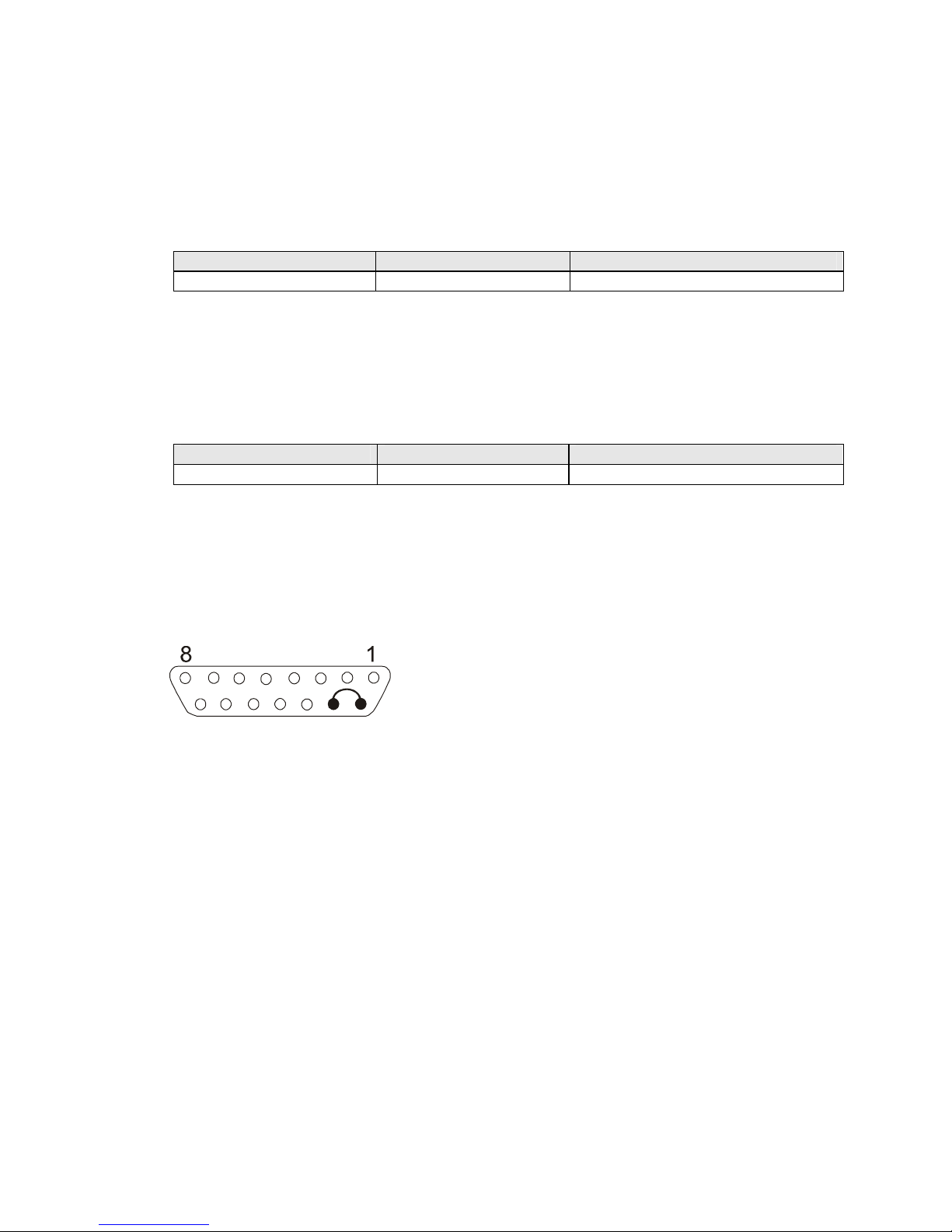
outputs No. 9 and 10 on connector CANNON 15 and simultaneous connection of supply
adapter to network.
5.2. Set-up of Direction Adding.
Some exchanges do not repeat pre-selection of number dialled before interconnection when
connecting call to transmitter with GSM gate. This function allows reconstruction of originally
dialled number by adding of removed pre-selection.
Instruction by Phone SMS Instruction Pre-set
0100n# PDIR n Not activated in production.
Where n is 0 to 7 figures, which shall be added
Removal of values by phone is carried out by instruction 0100# or by SMS message PDIR .
(point represents data) or PDIR ““
Example: Exchange removes pre-selection 0 from dialled number 0606-445566 and
transmits only number 606-445566 down the line.
● Enter programming regime with #pppp# (see paragraph 4.2.)
● Dial 01000#.
● Hang up.
From this moment GSM gate puts pre-selection 0 in front of each phone number read on
phone line. This means that number 606-445566 will be reconstructed to number 0606-
445566.
5.3. Set-up of Allowed Directions.
If you want to avoid connection of useless calls (which would have higher tariffs than when
connected through fixed line) through GSM gate set required values of pre-selections as
allowed directions. Other calls, e.g. calls into fixed local or toll phone network, will not be
connected through GSM gate.
n is 1 to 7-figure-number of pre-selection
Removal of values is carried out by instruction 0201#, 0202#, etc. or by SMS message
ADIR1 . (point represents data) or ADIR ““
Page 9
8
Instruction by Phone SMS Instruction Pre-set
0201n# ADIR1 n 0601 Eurotel
0202n# ADIR2 n 0602 Eurotel
0203n# ADIR3 n 0603 Paegas
0204n# ADIR4 n 0604 Paegas
0205n# ADIR5 n 0605 Paegas
0206n# ADIR6 n 0606 Eurotel
0207n# ADIR7 n 0607 Eurotel
0208n# ADIR8 n 0608 Oskar
0209n# ADIR9 n 0723 Eurotel
0210n# ADIR10 n 4 Internet call
0211n# ADIR11 n 5 Internet call
0212n# ADIR12 n 0 Everything allowed
0213n# ADIR13 n Backup
0214n# ADIR14 n Backup
0215n# ADIR15 n Backup
0216n# ADIR16 n Backup
ATTENTION!
● If you remove all values GSM gate will not connect any calls except numbers, which
begin with code for unblocking, if it is set. After end of dialling of number you will hear
engaged tone.
● If you also allow connection of calls to fixed phone network change parameter “number
of figures” so that longer numbers can be connected, too.
● If you want to allow calls to all directions – tm. to fixed phone network either – set
number “0” as one of allowed numbers.
● If you use function of automatic switch-over to second SIM card according to dialled
number (parameter No. 19 – SIMDIR), set numbers of pre-selections from longest to
shortest. Priority of evaluation goes from above.
Example:
You want to disallow usage of gate for Paegas and fixed phone lines, and allow usage of
number with pre-selection 072 instead:
● Enter programming regime with #pppp# (see paragraph 4.2.)
● Dial 0203#0204#0212#02140724# and hang up or send SMS message XXpppp ADIR3
. ADIR4 . ADIR12 . ADIR14 072 (see chapter 4.3.)
From this moment numbers beginning with 0601, 0602, 072, 0606, 0607, 0608, 4 a 5 will be
allowed. Other calls will not be accepted by gate.
5.4. Code for Disallowed Directions.
Code for disallowed directions, dialled in front of phone number, allows dialling of numbers,
which are not in list of allowed directions. When dialling number into gate, calling is allowed
by dialling of correct code in front of phone number. Gate then removes code and sends
only phone number in GSM. We recommend to use in applications where gate is accessible
from public network after pre-selection.
Where n is 0 to 7 figures, which shall be removed
Instruction by Phone SMS Instruction Pre-set
0300n#... CDIR n ... Not activated in production.
Page 10
9
Removal of values is carried out by instruction 0300# or by SMS message CDIR . (point
represents parameter)
Example: You want to enter code for unblocking of disallowed directions 1234.
● Enter programming regime by dialling #pppp# (see chapter 4.2.)
● Dial 03001234# and hang up or send SMS message XXpppp CDIR 1234 (see chapter
4.3.)
From this moment GSM gate connects also phone numbers beginning with 1234 in addition
to allowed directions. This code will be removed and rest of dial will be sent into GSM.
5.5. Set-up of Fixed Pre-set to Extension.
Parameter is accessible only for gate GB 200 271. During incoming call pre-set by
frequency dialling from cell phone is awaited for set time (see 5.14.). If pre-set is not carried
out and line still has dialling tone gate carries out dial pulse of pre-set number of extension
after expiry of set time. This means that if no frequency pre-set is received from cell phone
incoming call is connected to set extension.
Where n is 0 to 7 figures – number of extension, to which incoming calls shall be connected
if no pre-set is received
Removal of values is carried out by instruction 0400# or by SMS message IDIR . (point
represents parameter) or IDIR ““
5.6. Ringing after Connection.
Some exchanges require ringing after initial connection of line onto input transmitter. This
function allows setting of switch-on of control ringing for required time. Function is not
accessible in GB 200 271.
Instruction by Phone SMS Instruction Pre-set
0500xx#... IRING xx ...
8, tm. 0.8s set from production
Where xx is number in range from 00 to 20 and means time in tenths of seconds, tm. 0.0 –
2.0s
5.7. Set-up of Delay before Dial.
After occupation of transmitter some exchanges cause glimmer of line, which could be
evaluated as number by GSM gate. This function allows setting of delay after moment of
pick-up. During this delay situation on line will be ignored. Function only for GB 200 171.
Instruction by Phone SMS Instruction Pre-set
0600xx#... DELAY xx ...
3, tm. 0.3s set from production
Where xx is number in range from 00 to 99 and means time in tenths of seconds, tm. 0.0 –
9.9 s
Instruction by Phone SMS Instruction Pre-set
0400n#... IDIR n ... Not activated in production
Page 11
10
5.8. Set-up of Waiting Time for Dial.
After picking up GSM gate gives you dialling tone, which notifies you about possibility of
dialling of number. After set time dialling tone changes to engaged tone and reading of
dialled phone number is terminated.
Instruction by Phone SMS Instruction Pre-set
0700ss#... TLINE ss ... 60, tm. 60s set from production
Where ss is number in range from 10 to 120 and means time in seconds, tm. 10 - 120s
5.9. Set-up of Number Control.
After dialling of last figure of number GSM gate waits for set time in case further number
is dialled. After expiry of this time reading of dial is terminated and dial is sent to GSM.
Instruction by Phone SMS Instruction Pre-set
0800ss#... TDIAL ss ... 4, tm. 4s set from production
Where ss is number in range from 01 to 20 and means time in tenths of seconds, tm.1-
20s
5.10. Set-up of Number of Figures after which Number Is Dispatched.
If set allowed directions of GSM gate are only cell phone numbers, which always have
maximum number of 10 figures, it is sensible to set 10 as maximum number of figures. After
setting of 10th figure dialling of number starts immediately without necessity of waiting for
control.
Instruction by Phone SMS Instruction Pre-set
0900nn#... LDIAL nn ... 10 set from production
Where nn is number in range from 03 to 24 and means maximum number of figures
5.11. Set-up of Dial Tone Type.
It is possible to set up different type of dial tone of GSM gate for each SIM card in order to
control that call is made through correct connection route.
Instruction by Phone SMS Instruction Pre-set
1001t#... TONE1 t ... 2 set from production for SIM1
1002t#... TONE2 t ... 3 set from production for SIM2
Where t is number from 0 to 4 and specifies type of dial tone (see chapter 6.1.)
5.12. Set-up of Programming Symbol # / *.
If symbol # is used by extension exchange for any service concurrent with functions of GSM
gate it is possible to set that symbol * is used exclusively in all instructions instead of symbol
#.
Instruction by Phone SMS Instruction Pre-set
1100z#... FLAG z ... 0, tm. # is set from production
Where z is 0 or 1 where 0 means usage of # and 1 means usage of *
Page 12
11
5.13. Set-up of Tariffs.
Parameter allows optimal setting of way of transmission of information about start-up and
length of GSM call to extension exchange.
Instruction by Phone SMS Instruction Pre-set
1200k#... TARIF k ... 0, tm. no tariff set from production
Where k is 0 to 63
0 No transmission
1-60 Periodical impulse 16 kHz in interval from 1 to 60s
61 Change of polarity when picked up by called party (for GB 200 171)
62 Flash impulse when picked up by called party (for GB 200 271)
63 16 kHz impulse when picked up by called party
5.14. Termination of Call when Line Is Silent.
Parameter only for GB 200 271. If exchange terminates phone call between extensions for
any reason and engaged or dial tone is not emitted and in addition opposite GSM
participant does not hang up it can happen that call in GSM stays uncollected. For this case
it is possible to activate monitoring of silence on line. If silence on line is longer than one
minute, call shall be disconnected if this function is activated.
Instruction by Phone SMS Instruction Pre-set
1300z#... SPEECH z ... 1, tm. function activated, set from
production
5.15. Time for Pre-set.
During incoming call from GSM gate GB 200 271 picks up extension line and awaits pre-set
by frequency dialling from cell phone for set time. If pre-set is not carried out set number of
extension is automatically dialled by pulse dial (see chapter 5.4.).
Instruction by Phone SMS Instruction Pre-set
1400ss#... WAIT ss ... 5, tm. 5s set from production
Where ss is 1 to 25 s
Transit of frequency pre-set from GSM into phone exchange is not reliable in some cases.
This problem can be solved by reinforcement of sensitivity of frequency dial receiver of
particular extension line in exchange.
5.16. Transmission of SMS Messages into PC.
If you want to use function of reception of SMS messages by connected PC through RS232
it is necessary to activate dispatch by this function. If function is active and SMS messages
are though not read from GB 200 by PC it can mean that SMS memory in GB 200 is full.
Further SMS messages are then not accepted and it might therefore happen, that control
instruction included in SMS message is not carried out. If function is switched off all
eventual instructions included in incoming SMS messages are carried out and all SMS
messages are deleted.
Instruction by Phone SMS Instruction Pre-set
1500z#... HOSTSMS z ... 0, tm. function switched off, set
from production
Where z is 0 or 1 - 0 off, 1 on
Page 13
12
5.17. Switch-on of SIM Card.
All function related to particular SIM card can be switched off by this parameter regardless
of other set-up. GB 200 will never try to switch over to switched-off SIM card.
Instruction by Phone SMS Instruction Pre-set
1601z#... SIMON1 z ...
SIM1 – 1 set from production
1602z#... SIMON2 z ...
SIM2 – 1 set from production
Where z is number 0 or 1 - 0 = SIM off, 1 = SIM on
5.18. Set-up of Base SIM Card.
If both SIM cards are switched on by function 5.16 SIM card, which was used as last one
(on which last call was automatically connected according to pre-set of number and function
5.19 SIMDIR.), will be activated.
Since inactive SIM card does not accept either incoming calls or SMS messages it is
recommended to choose one of the SIM cards as base.
If automatic switch-over to other SIM card is carried out 1 minute after termination of call on
this SIM card GSM will be switched back to set base SIM card.
Instruction by Phone SMS Instruction Pre-set
1701z#... SIMPRIM1 z ... SIM1 – 1 set from production
1702z#... SIMPRIM2 z ... SIM2 – 0 set from production
Where z is number 0 or 1 - 0 = SIM is not base, 1 – SIM is base
5.19. Blocking of SIM Card by PIN.
If your SIM card is blocked by PIN for safety reasons it is necessary to ensure that this PIN
is entered at each switch-on of GSM module. Activation of this function for SIM1 or SIM2
ensures automatic entering of PIN SIM1 and PIN SIM2 (see chapter 5.0).
Instruction by Phone SMS Instruction Pre-set
1801z#... SIMBLOK1 z ... SIM1 – 1 set from production
1802z#... SIMBLOK2 z ... SIM2 – 1 set from production
Where z is number 0 or 1 - 0 = SIM is not blocked, 1 = SIM is blocked
5.20. Assignment of SIM Cards to Allowed Pre-selections.
It is possible to add parameter, which SIM card to use for connection, eventually if it is
possible to use both cards, to each allowed pre-selection (see chapter 5.2). If dialled preselection of number is assigned to other SIM card than to the one, which is just registered in
GSM network, automatic switch-over to other card is carried out. If both cards are allowed
the one, which is just registered in network, is used.
Page 14
13
Instruction by Phone SMS Instruction Pre-set
1901m# SIMDIR1 m 0, tm. both SIM cards
1902m# SIMDIR2 m 0, tm. both SIM cards
1903m# SIMDIR3 m 0, tm. both SIM cards
1904m# SIMDIR4 m 0, tm. both SIM cards
1905m# SIMDIR5 m 0, tm. both SIM cards
1906m# SIMDIR6 m 0, tm. both SIM cards
1907m# SIMDIR7 m 0, tm. both SIM cards
1908m# SIMDIR8 m 0, tm. both SIM cards
1909m# SIMDIR9 m 0, tm. both SIM cards
1910m# SIMDIR10 m 0, tm. both SIM cards
1911m# SIMDIR11 m 0, tm. both SIM cards
1912m# SIMDIR12 m 0, tm. both SIM cards
1913m# SIMDIR13 m 0, tm. both SIM cards
1914m# SIMDIR14 m 0, tm. both SIM cards
1915m# SIMDIR15 m 0, tm. both SIM cards
1916m# SIMDIR16 m 0, tm. both SIM cards
Where m is 0, 1 or 2 - 0 = both SIM cards, 1 = only SIM1, 2 = only SIM2
ATTENTION!
Switch-over to other SIM card lasts approx. 25s therefore it is not recommended to use this
function in applications with high density of phone service.
So as pre-selections are correctly evaluated numbers of pre-selections must be set from
longest to shortest. Priority of evaluation goes from above.
5.21. Number for Information SMS Messages.
GB 200 allows automatic dispatch of information about changes in configuration, operation
time and about RESET. Information is sent as SMS message to set cell phone number if
this number is entered in following way:
Instruction by Phone SMS Instruction Pre-set
2000n#... INFOSMS n ...
Not activated in production
Where n is 1 to 15 figures of cell phone number
Removal of values is carried out by instruction 2000# or by SMS message INFOSMS .
(point represents data)
5.22. Set-up of Number for Monthly Upkeep Calling.
Not to forfeit credit of GO card, EUROTEL requires to carry out at least one paid phone
connection in 3 months from this card. So that user, which uses GB 200 for protection of
properties, does not have to think of this matter it is possible to enter number, which gate
automatically calls each month of operation, in GB 200.
Instruction by Phone SMS Instruction Pre-set
2100n#... MCALL a ... Not activated in production
Where n is 1 to 5 figures of number
Removal of values is carried out by instruction 2100# or by SMS message MCALL . (point
represents data)
Page 15
14
If you want to use this service it is recommended to set number of your fax or number
0214112 (time information). It is not recommended to set your cell phone number because
GB 200 does not use real time and call can come during night.
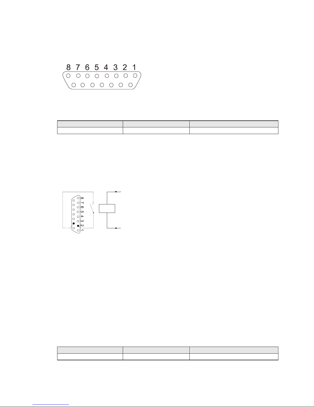
5.23. ALARM SMS Messages and Set-up of A-numbers for SMS Despatch.
8 input/output signals are taken out on connector CANNON 15 of GB 200 (outlets No.1 - 8)
One of eight prepared texts can be dispatched in
form of SMS message to two cell phone numbers or
to service centre of operator by activation of each
input (by decrease of voltage under limit of 0.8V for at
least 0.5s). It is possible to enter A- and B-numbers
for dispatch of SMS message to each of inputs No. 1
– 8.
Instruction by Phone SMS Instruction Pre-set
220vn#... SMSNOAv n ... Not activated in production
Where v is number of input from 1 to 8
Where n is 1 to 15 figures of cell phone number or number of service centre of operator.
Numbers can be entered both in national and international format (0606445566 or
+420606445566).
Recommended linkage of input, example for input No. 2
Connector CANNON15
Description of linkage of outlets:
1-8 input / output No. 1 - 8
9 input INIT
10-14 GROUND
15 + 5V max./ 400mA
Since output works at the same time also as input set-up of logical level 0 on output avoids
activation of dispatch of SMS message from particular input (see chapter 5.26 function
OUTv h). Counterpart of connector CANNON15 including plastic cover can be ordered
additionally as accessories.
If you want to dispatch message about activation of SMS input to e-mail or fax it is
necessary to set number of service centre of operator as SMS number: Eurotel: 999111 or
Paegas: 4616. Prepared SMS texts (see chapter 5.25) shall be filled in according to
operators’ directions.
In case call is just made through GB 200 it is terminated immediately and all alarm actions
are carried out.
5.24. Set-up of numbers for ALARM SMS Messages – SMS B-number.
Second number of each input for dispatch of prepared text of SMS message No. 1 - 8:
Instruction by Phone SMS Instruction Pre-set
230vn#... SMSNOBv n ... Not activated in production
Where v is number of input No. 1 - 8
Where n is 1 to 15 figures of cell phone number or number of service centre of operator
9
10
15
9
1
0
15
RE
1
Page 16
15
5.25. Set-up of Numbers for ALARM Calling.
Particular set phone number will be dialled simultaneously to activation of input No. 1 to 8
and called party will hear warning tone from GB 200 after pick-up.
Instruction by Phone SMS Instruction Pre-set
240vn#... ALARMCALLv n Not activated in production
Where v is number of input No. 1 - 8
Where n is 1 to 15 figures of number to any phone
5.26. Set-up of Text of ALARM SMS Messages.
Set text of message, which is dispatched in case of input activation, is assigned to particular
input No. 1 - 8. Text can be changed by following instruction:
Instruction by Phone SMS Instruction Pre-set
250vtext#... SMSTXTv “text“ Set from production: ALARMv
Where v is number of input No. 1 - 8
Where text is entered as numeric values according to ASCII table through phone line, in
SMS message text is closed into quotes
5.27. Set-up of Logical Level of Outputs.
Each input No. 1 - 8 is also output at the same time.
Value of logical level of particular output can be changed in following way:
Instruction by Phone SMS Instruction Pre-set
260vh#... OUTv h log. 1 for all outputs set from production
Where v is number of input No. 1 - 8
Where h is required logical level of 0 or 1
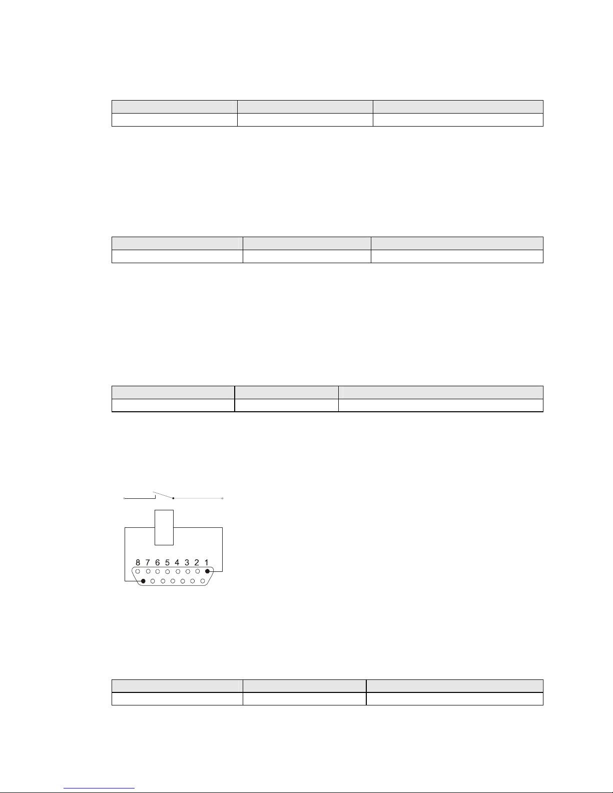
Recommended linkage of outputs with galvanic detachment, example for output No.
1:
5.28. Statement of All Set-up Parameters.
Complete statement of configuration can be required by SMS message from cell phone.
This statement comes in the form of minimum 6 SMS messages to cell phone of sender of
instruction.
Instruction by Phone SMS Instruction Pre-set
LIST
Form of statement of parameters: Instruction1=parameter1
Instruction2=parameter2 … see chapter 4.2
9
10
15
R
E
1
Page 17
16
You can add XXpppp in front of each SMS message, which you received this way, change
values of required parameters and send the message back as new values of configuration.
5.29. RESET of Gate and Time Counters.
It is possible to carry out remote RESET of GB 200 by means of SMS message. Action is
equivalent to switch-on of charging tm. start-up of program, switch-off and on of GSM
module and login in network. However, in this case counters of time in operation are cleared
either.
Instruction by Phone SMS Instruction Pre-set
RESET
5.30. Initialisation of Gate to Initial Set-up from Production.
Remote initialisation of GB 200 can be carried out by means of SMS message. All
adjustable parameters except PINs and blocking of SIM card are set to initial values set
from production. At the same time RESET is carried out (for range of reset see chapter
5.28).
Instruction by Phone SMS Instruction Pre-set
INIT
SMS message as well as all other SMS instructions requires entering of heading with actual
PIN of SIM card XXpppp in front of instruction (see chapter 4.2). If you do not know this PIN
it is necessary to carry out configuration from PC or hardware initialisation in following way:
Interconnect PINs No. 9 and 10 of connector CANNON15 and simultaneously connect GB
200 to power supply. Greed LED flashes quickly and gate is in initial set-up.
6. Operation.
6.1. Outline of Tones.
Without dialling tone
Dialling tone of dial No. 1
Dialling tone of dial No. 2
Dialling tone of dial No. 3
Tone "programming"
Tone "engaged"
Ringing and tone of ringing
Warning tone
6.2. Operation during Current Outage.
It is not possible to make calls during current outage. Therefore we recommend connecting
of network supply from backed up power supply UPS or connecting of backup power supply
from battery 12V. Programmed configuration will be saved in memory - type EEPROM – for
arbitrarily long time during current outage.
9
10
15
Page 18
17
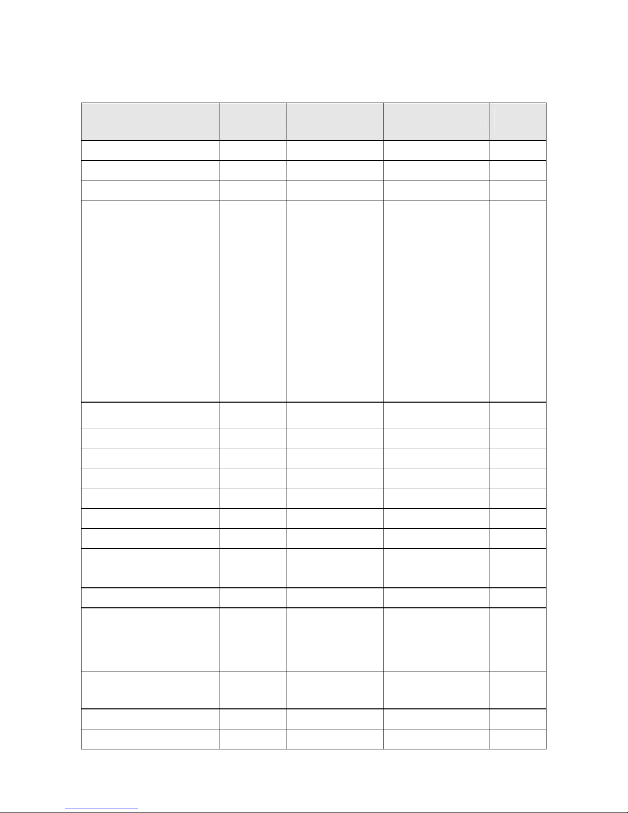
7. List of Programming Instructions.
Switch-over into programming regime is carried out by dialling #pppp# on phone line.
Code XXpppp must forgo instructions in each control SMS message.
pppp is PIN of GSM Gate.
Instruction
By phone
#pppp# …
SMS instruction
XXpppp …
Range
Initial
values
PIN for SIM1 – main PIN 0001pppp# PIN1 pppp 4 figures of PIN 0000
PIN pro SIM2 0002pppp# PIN2 pppp 4 figures of PIN 0000
Adding of direction 0100n # PDIR n n = . or 1-7 figures -
Allowed directions
0201n #
0202n #
0203n #
0204n #
0205n #
0206n #
0207n #
0208n #
0209n #
0210n #
0211n #
0212n #
0213n #
0214n #
0215n #
0216n #
ADIR1 n
ADIR2 n
ADIR3 n
ADIR4 n
ADIR5 n
ADIR6 n
ADIR7 n
ADIR8 n
ADIR9 n
ADIR10 n
ADIR11 n
ADIR12 n
ADIR13 n
ADIR14 n
ADIR15 n
ADIR16 n
n = 1-7 figures
or
n = . clears out
parameter value
1
2
3
4
5
6
7
8
9
0
-
-
-
-
-
Code for disallowed
directions
0300n # CDIR n n = . or 1-7 figures -
Fixed pre-set *2 0400n # IDIR n n = . or 1-7 figures Ringing after switch-on *1 0500xx # IRING xx xx = 00-20 s/10 8s /10
Delay before dial *1 0600xx # DELAY xx xx = 00-20 s/10 3s /10
Waiting for dial 0700ss # TLINE ss ss = 10-99 s 60s
Time of number control 0800ss # TDIAL ss ss = 01-20 s 4s
Number of figures 0900nn # LDIAL nn nn = 03-24 figures 10
Dialling tone of SIM1 1001t # TONE1 t t = 0-4 see tones 2
Dialling tone of SIM2 1002t # TONE2 t t = 0-4 see tones 3
Programming symbol 1100z # FLAG z z = 0..#, z = 1.. * 0
Set-up of tariffs 1200k # TARIFF k 0 - switched-off
1-60 pulse 16kHz
61 - polarity
62 - flash
63 - 1 pulse 16kHz
0
Instruction By phone
#pppp# …
SMS instruction
XXpppp …
Range Initial
values
Termination at silent line*2 1300z # SPEECH z z = 0 off, 1 on 1
Time for pre-set *2 1400ss # WAIT ss ss = 00 -25s 5s
Page 19
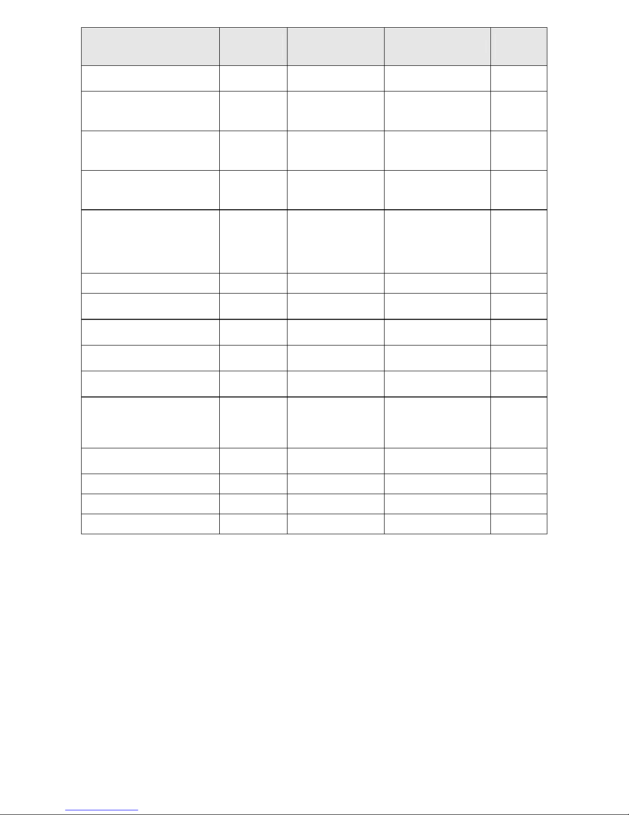
18
Instruction
By phone
#pppp# …
SMS instruction
XXpppp …
Range
Initial
values
SMS message into PC
through RS 232
1500z # HOSTSMS z z = 0 off, 1 on 0
Switch-on of SIM1 1601z # SIMON1 z z = 0 off, 1 on 1
Switch-on of SIM2 1602z # SIMON2 z z = 0 off, 1 on 1
Initial SIM1 1701z # SIMPRIM1 z z = 0 off, 1 on 1
Initial SIM2 1702z # SIMPRIM2 z z = 0 off, 1 on 0
Blocking of SIM1 by PIN 1801z # SIMBLOK1 z z = 0 off, 1 on 1
Blocking of SIM2 by PIN 1802z # SIMBLOK2 z z = 0 off, 1 on 1
Assignment of SIM cards
to allowed directions
19ppm # SIMDIRpp m pp – allowed
directions 1 – 16
m = 0 both SIM
m = 1 SIM1
m = 2 SIM2
all 0
Number for info. SMS 2000n # INFOSMS n n =. or 1-15 figures Number for monthly
calling
2100n # MCALL n n =. or 1-15 figures -
Number SMS ALARM A 220vn # SMSNOAv n v = input 1-8
n =. or 1-15 figures
Number SMS ALARM B 230vn # SMSNOBv n v = input 1-8
n =. or 1-15 figures
Numbers for ALARM
calling
240vn # ALARMCALLv n v = input 1-8
n =. or 1-15 figures
Set-up of SMS message
texts
250vtext # SMSTXTv “text“ v = input 1-8
text – ASCII
“text“ – SMS text v
““ max. 160 fig.
Alarmv
Set-up of outputs 260vh # OUTv h v = input 1-8
h = 0 or 1
all 1
Statement of set-up LIST RESET RESET Initialisation INIT -
Numbers can be entered in national format – e.g. 0606445566 but also in international format –
e.g. 420606445566. Numbers in international format cannot be entered through phone line.
Page 20

19
8. Subsidiary Programs for PC.
Installation floppy disc 3.5“ is a part of equipment delivered with product and contains installation
file for subsidiary programs for GB 200. Minimum required configuration: Windows95, 98, PC 486,
16MB RAM, 3.5“ drive
8.1. Installation.
Insert installation floppy disc into drive A: or B:
Start installation by command A:\SETUP or B:\SETUP
Follow instructions from installation guide
8.2. GB200cfg - Program for Configuration of GB 200 from PC.
Program answers the purpose of comfortable and transparent configuration of GB 200 and
allows following functions:
Edit of all parameters of GB 200.
Opening/ saving of configuration from file / in file and from GB 200 / into GB 200.
Set-up of communication port for GB 200.
Display of level of GSM signal.
8.3. GBserver – Program for Distribution of SMS Messages between GB200 and Network
Client.
Program running on PC, to which GB 200 is connected, allows distribution of incoming and
outgoing SMS messages between GB 200 and clients of computer LAN net.
Basic functions of program are:
Set-up of communication port or GB 200.
Set-up of port of TCP network protocol on LAN net.
Pre-set communication port of TCP network protocol is 5010, in case this port is engaged
in your network choose another port number.
8.4. GBsms – Program for Reception and Dispatch of SMS Messages.
Program running on PC of LAN net client, on which program GBserver runs, allows
reception and despatch of SMS messages through GB 200.
Set-up of TCP protocol port on LAN net: set the value identical to setting on GBserver
Set-up of IP address: set IP address of PC, on which GB server runs. This can be found
by start-up of command on command prompt in Windows WINIPCFG.
Page 21
20
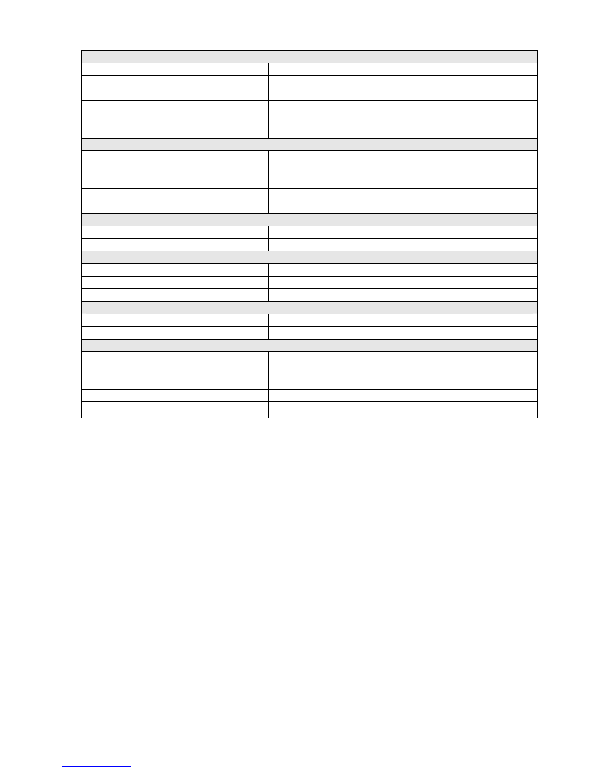
9. Basic Technical Parameters.
Line GB 200 171
Dialling of number Dial pulse or tone dialling
Line voltage 48 V
Ringing 35 Vef. 50Hz - 1s / 4s
Tones 425 Hz
Impulse 16 kHz 16000Hz ±0,1%, 35 ms, min. 150mV
Connecting connector RJ 12
Line GB 200 271
Reading of number dialling Tone dialling
Ringing detection 20 - 60 Hz
Transmission of fixed pre-set Dial pulse
Line voltage 24 - 60 V
Tones 425 Hz
SMS inputs
CANNON15 No. 1 - 8 log. 0 0 - 0.8 V
log. 1 3.8 – 12 V
SMS outputs
CANNON15 No. 1 - 8 log. 0 max. 0.4 V max. Iz = 300mA
log. 1 3.5 - 5 V at Iz = 0,3mA
CANNON15 No. 15 +5V max. load 200 mA
GSM network
GSM 900 MHz / 1800 MHz
SIM card Plug-in
Device
Power supply voltage 10.5 -16V ss (network adapter12 V / 500mA)
Power take-off Max. 6 W, at rest 1,5 W
Size 230 x 160 x 47 mm
Weight 450 g
Operational temperatures
from +5 to +40 oC
Page 22
21
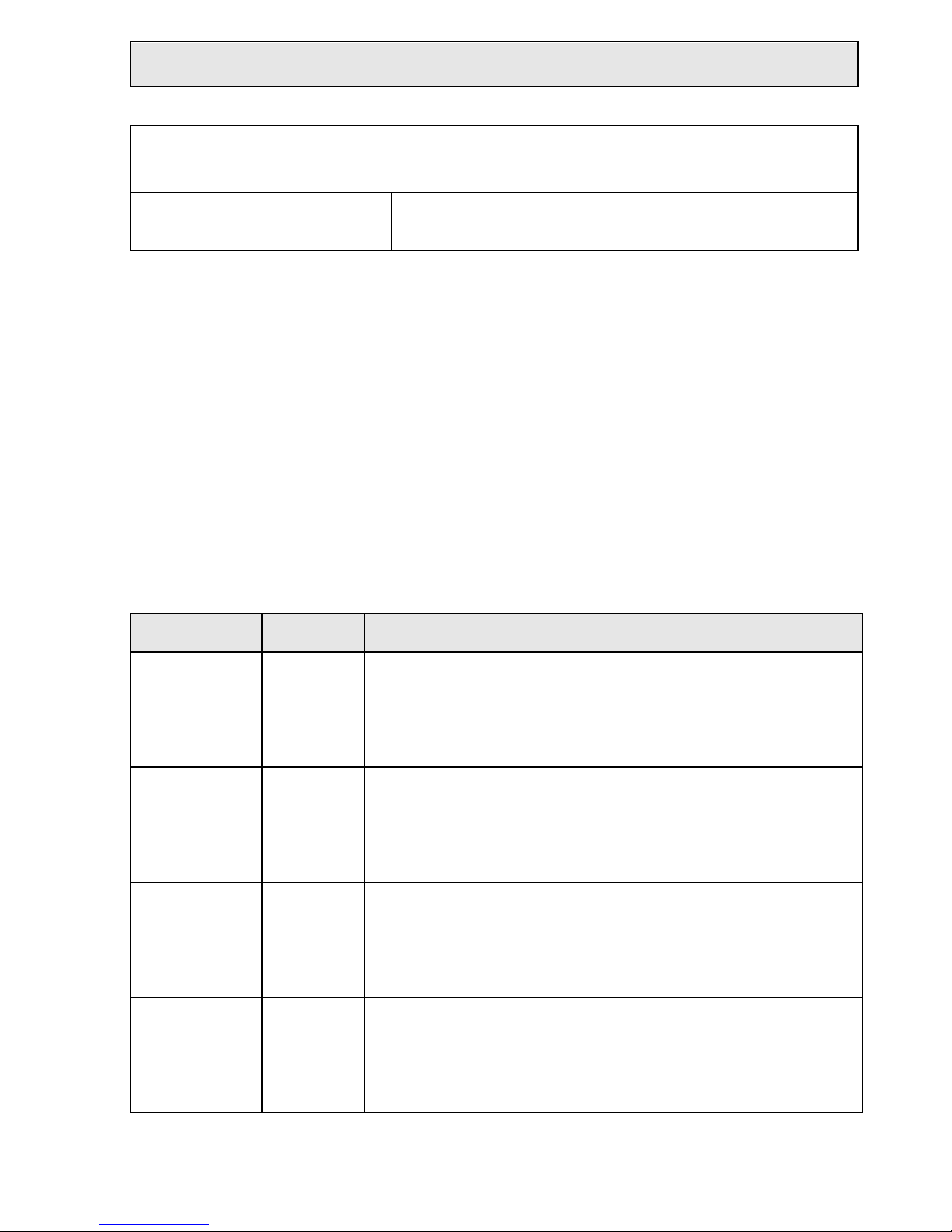
GUARANTEE CERTIFICATE
Product name:
Type :
Production number: Date of sale: Signature:
Selling organisation:
Address, phone No., stamp:
Date of
receipt
Date of
dispatch
Description of defect
Page 23

22
GUARANTEE CONDITIONS
Length of guarantee period is 12 months from date of sale. Guarantee applies only to goods
registered or identified by company LEVEL.
Guarantee repair will be carried out at latest within 10 working days after receipt of defective
goods by company LEVEL provided that spare part is disposable in store. If it is not possible
alternative solution will be offered to user for the time of repair.
Guarantee repairs will be carried out in company seat and guarantee period shall be lengthened
by the time of repair. Technician is solely responsible for choosing the way of transport.
Guarantee is not provided in case of loss or replacement of Guarantee Certificate, damage of
product caused by natural disaster, during transport, by unsuitable positioning, unsuitable
handling, operation of device in unsuitable conditions, or in case of damage or removal of sealing
labels.
Guarantee does not apply to expendable property – dyeing ribbons, floppy discs, etc. It does not
apply to malfunction caused by installed software or interference, too. Company is not responsible
for possible losses, which originate from device failure either.
Guarantee does not apply to malfunction caused by change of external conditions as change in
legislation, change of phone network, change of supply network, etc.
Guarantee is applied at presentation of completely filled-in Guarantee Certificate and device
intended for repair including accessories.
Duplicate of Guarantee Certificate is not issued, customer guarantees its correctness and
originality.
Page 24

23
GB 200@003 (C) LEVEL, 2002
LEVEL Ltd., Plhovská 1997, Nachod 547 01, CZECH REPUBLIC
www.levelna.cz
 Loading...