

Page 1

CAR ALARM GSM,GPRS,GPS
Set GB 060 515 C
Controlled by wireless access card
User Guide to Installation and Operation
Page 2

2
Page 3

Dear customer,
You have purchased our product – GSM CAR ALARM GB 060 515C. You have
received highly modern product with high quality that offers not only effective GSM
security of vehicle, cabin, freight space and crew but also many other features:
GSM security with silent alarm, sends SMS messages and ringing to mobile
phone of owner or to security agency. Silent alarm will not wake up your neighbors
in case of a false alarm!
Automatic activation and deactivation of car alarm by access card – by only
reaching the range of card reader installed in the vehicle.
Exact localization of vehicle with GPS coordinates sent to mobile phone of
owner of to security agency dispatch.
Remote shutdown of vehicle by sending SMS command when speed decreases
under 10 km/h.
Listening and voice call to vehicle cabin to discourage robbers, for
communication with crew or to detect false alarms.
Navigation for driving with connection to a PDA or laptop. Works only as GPS
receiver, navigation is done by installed navigation software.
Electronic log book, vehicle tracing, fleet management, provides data about
vehicle operation, GPS coordinates and events report to logistic and car security
service providers.
Dear customer, for optimal use of the GB 060 515C Car Alarm we recommend to
read carefully this User Guide. Once you get to know how to operate the product,
the operation is on the level of operating a mobile phone. Installation and putting
product into operation requires detailed knowledge about car alarms installation.
Installation of product in vehicle should be done by specialized company.
3
Page 4

LEVEL Ltd.
Contents
1. Description and Features …………………………………………………… 5
1.1. Description of the GB 060 515C Car Alarm Unit………………….. 5
1.2. Recommended Set and Connections .............…………………….. 6
1.3. Standard Set and Optional Accessories ………….…………..……. 7
1.4. Summary Table of GSM Alarms and Messages ...………………… 7
1.5. Access Card Features ………………...……………………………… 8
1.6. Emergency Button Features …………………………………………. 8
1.7. Signalization LED in Vehicle ...........………………………………… 8
1.8. GPRS for Online Electronic Log Book of Rides ......……………….. 9
1.9. Navigation ...........……………………………………………………… 9
2. Operation, Configuration ……………………………………………………… 9
2.1. Quick Start ……………………………………………………………. 9
2.2. Configuration and Operation - SMS Commands Table .………… 10
2.3. What to do when something doesn’t work ..………………………. 14
3. Installation ……………………………………………………………………. 14
3.1. Condition for Use, Safety …………………………………………… 14
3.2. Connections Drawing ……………………………………………….. 15
3.3. Hints for installation …………………………………………………. 16
3.4. Checking Functionality ………………………………………………. 17
4. Technical parameters, Maintenance ………………………………………. 18
4.1. Technical parameters …………………………………………………18
4.2. Maintenance ..………………………………………………………… 21
Warranty Conditions ………………………………………………………………. 21
Warranty Certificate ..……………………………………………………………….22
4
Page 5
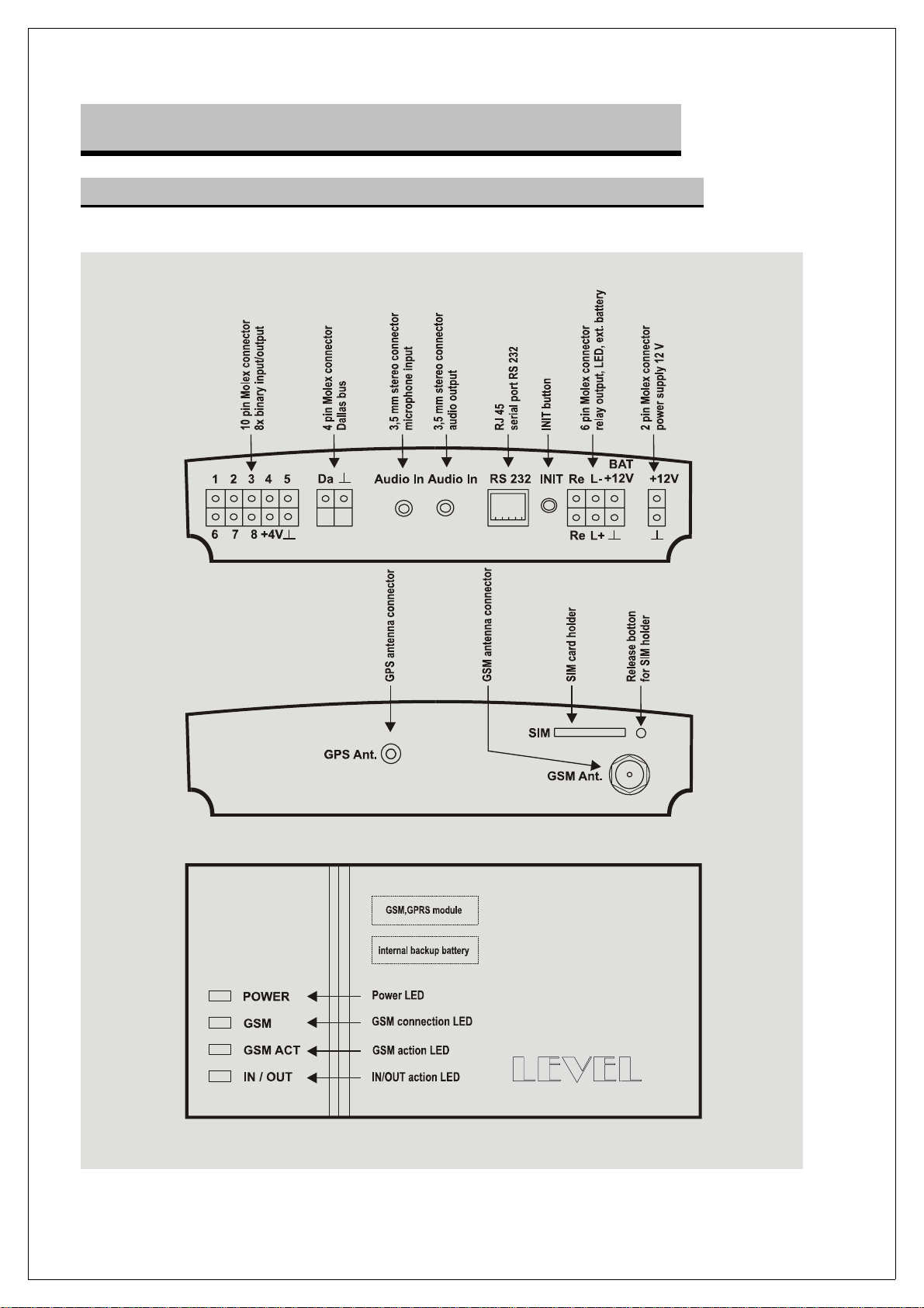
1. Description and Features
1.1. Description of the GB 060 515C Car Alarm Unit
5
Page 6
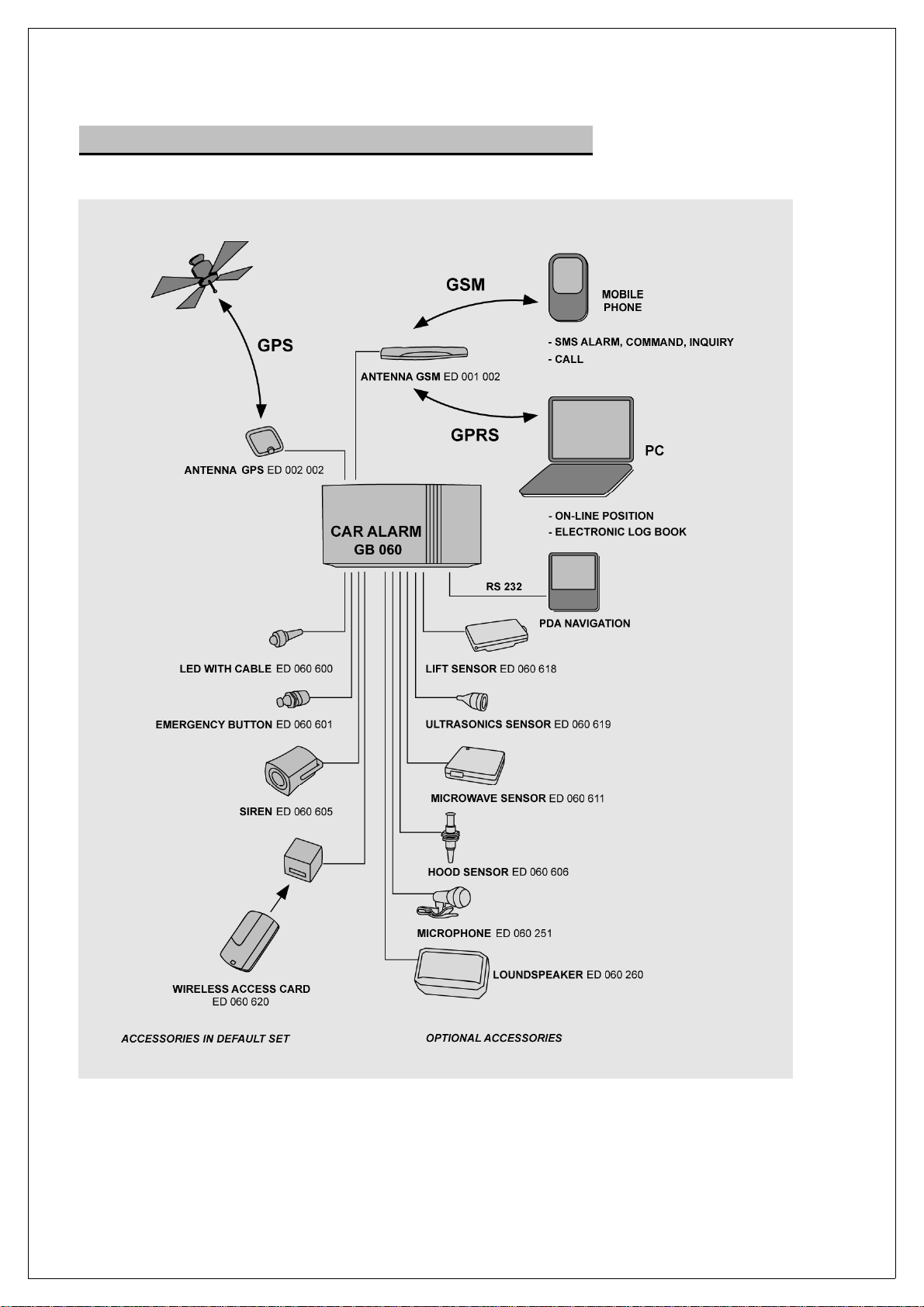
1.2. Recommended Sets and Connections
6
Page 7

1.3. Standard Set and Optional Accessories
Accessories in Default Set
GB 060 515C
ED 001 002
ED 002 002
ED 060 620
ED 060 601
ED 060 600
ED 060 605
CB 161 002
CB 161 006
CB 161 011
CB 161 000
ED 060 621
ED 060 618
ED 060 619
ED 060 611
ED 060 606
ED 060 251
ED 060 260
CB 160 021
CB 160 017
GSM, GPRS, GPS Car Alarm Unit
GSM antenna flat, self-adhesive
GPS antenna active
Wireless access card reader and + 2 cards
Emergency button with 2m cable
Control LED
HITPOINT Siren
2-pin cable with MOLEX connector
6-pin cable with MOLEX connector
10-pin cable with MOLEX connector
Mounting set
Optional Accessories
Replacement wireless access card
Tilt sensor
Ultrasonic motion sensor
Microwave motion sensor
Hood sensor
External microphone
Active loudspeakers
Cable RS 232 from GB060 to a PC
Reduction RS 232 from GB060 to a PDA
1.4. Summary Table of GSM Alarms and Messages
Alarm description SMS Text • Ringing
Unauthorized ignition
Unauthorized manipulation
Unauthorized entry
Emergency button
Message description
Power supply disconnected
Low level of backup battery
Power supply restored
Vehicle shutdown
Unit status (once a week)
Low prepaid credit
*1) alarm ok; power: <POWER>; gsm: <GSM>; tacho: <TACHO>; position: <GPSD>
alarm – ignition
alarm - lift sensor
alarm - room sensor
emergency call
Text SMS
alarm - power off
alarm - battery low
power restored
stop.Run
alarm ok … *1)
alarm - credit low: <credit>
After alarm, all sensors are blocked for 3 minutes.
When alarm signalized by ringing, the ringing will be one times for 40
seconds. Alarm in progress can be interrupted by starting ignition with
connected access card or by SMS command.
Tel1 Tel2 Tel3 Tel4
• □
• □
• □
•
Tel1 Tel2 Tel3 Tel4
•
•
•
•
•
•
• □
• □
• □
•
•
•
•
-
-
-
•
•
•
•
•
•
•
-
-
-
•
•
•
•
•
•
•
-
-
-
7
Page 8

1.5. Access Card Features
Car alarm is equipped with access card reader and it is permanently armed. Each
access is verified by enquiry to access card presence. If no access card is detected
in the range within 20 seconds, the unit will launch silent alarm. Range of access
card reader is up to 10 meters. Usual time of successful detection of access card is
less than 5 seconds.
Buttons on ID card can active or deactivate card and put the reader into learning
mode. The cards are deactivated from production and must be activated before first
use.
Activation of card is done by pressing any button for 1 second. The LED on card
will blink two times.
Deactivation of card is done by pressing two buttons marked oo and o o for 1
second (both at the same time). LED on card will blink once.
Learning mode enables adding other ID cards into the system. Connect the reader
to 12 V power supply – and switch on the ignition key. Wait 10 seconds for
successful authorization of cooperating ID card to the system (card reader relay will
close, LED will stop blinking). Press the two buttons oo and o o on cooperating
card at the same time, hold them for about 8 seconds. LED on ID card must blink
quickly for 4 seconds. Within 10 seconds after this do the same operation on card
that should be added in the system (press the two buttons oo and o o at the same
time). The system can cooperate with up to four cards.
The access card contains two 3 V batteries CR 2025, one battery provides energy
for the card operation and the second battery is marked as “spare battery“ is for
replacement when the main battery runs flat. Battery life is approximately 6 months.
1.6. Emergency Button Features
Blocking alarms before next ignition start
Press the emergency button for a short time – up to 1.5 seconds.
Manual alarm in case of accident or emergency situation
Press the emergency button for longer than 1.5 seconds. Release the button after
the LED is switched off.
1.7. Signalization LED in Vehicle
LED not blinking vehicle is disarmed
LED blinks shortly once per second vehicle is armed
LED blinks shortly twice per 3 seconds vehicle is armed, no GSM signal
LED blinks quickly searching for access card
LED on permanently call or data connection in progress
8
Page 9
1.8. GPRS for Online Electronic Log Book of Rides
GSM Car Alarm GB 060 515C is equipped with GPRS, that provides cost-effective
on-line transmission of collected data (GPS coordinates, tachometer status, report
of events, etc…) for further processing in various services – for example for online
supervision over the vehicle via internet, online electronic log book of rides, etc.
To find out more about these services contact the manufacturer at www.levelna.cz
1.9. Navigation
Connect the GSM car alarm with laptop or PDA with installed map software.
Navigation on laptop computers was tested with software products AUTOROUTE,
ROUTE 66 and MAPPOINT. Navigation on PDA was tested Tom Tom and Pocket
Kim. GSM car alarm works as GPS receiver, navigation features fully depend on the
navigation software.
For connection with a laptop use cable CB 160 021
For connection with a PDA use cable CB 160 021 and reduction CB 160 017
2. Operation, Configuration
2.1. Quick Start
Inserting SIM card
Insert the SIM card in the holder on upper side of the GSM Car Alarm. The holder
can be pulled out by pressing the yellow button. SIM card should not be blocked by
PIN, should have enough of prepaid credit, erased all SMS and activated data
services.
Settings and change of PIN
The default PIN in unit is set to 1234. It is possible to change the PIN via SMS
command from any mobile phone: 1234_pin_xxxx (replace x with new PIN, put
space instead of _). When PIN is changed, the unit will reply with SMS message.
Configuration of phone numbers
SMS
Reply
Value x
Value y
pin_telx_y
telx.Value_“y“
1 – phone number of driver 1 or administrator
2 - phone number of driver 2
3 - phone number of driver 3
4 - phone number of driver 4 or security agency
Phone number in international format (+420...)
9
Page 10

Activation and Adding New Access Card
The card is deactivated from production and it needs to be switched on before use.
It will be switched by pressing any button for one second, LED on card will blink two
times.
2.2. Configuration and Operation – SMS Commands Table
GSM Car Alarm must be equipped with a SIM card. It is recommended to use a
pre-paid SIM card with no monthly fees. Setting and operation with car alarm can
be done by SMS messages.
Format of SMS commands - lower or upper case make no difference.
PIN four-digit safety code (default 1234)
space (marked as _ in text)
COMMAND name of command for required change of settings
space (marked as _ in text)
PARAMETER value, ? or . , some commands have no parameter
One SMS can contain up to 4 commands with parameters.
PIN_command1_parameter1_command2_parameter2_command3_parameter3_command4_parameter4
To erase value from car alarm memory, insert . (dot) instead of parameter.
Car alarm confirms executing all commands by SMS message.
Summary table of SMS commands
Change of PIN
Settings
List of phone numbers
Settings
Erasing
SMS
Reply
Value x
Set to x
SMS
Reply
Value x
Value y
SMS
Reply
Value x
Value ““
1234_pin_xxxx
pin_xxxx
0 to 9
1234
pin_x_y
x.Value_“y“
tel1 - phone to driver 1 or administrator
tel2 - phone to driver 2
tel3 - phone to driver 3
tel4 - phone to driver 4 or sec. agency
Phone number in international format
pin_x_.
x.Value_““
tel1-tel4 (see phone numbers settings)
Phone number not defined
10
Page 11

Inquiry
Date and time
SMS
Reply 1
Reply 2
Value x
Value y
Value ““
pin_x_?
x.Value_y
x.Value_““
tel1–tel4 (see phone numbers settings)
Phone number in international format
Phone number not defined
Settings
SMS
Reply
dd–mm-yy
hh:mm:ss
Inquiry
SMS
Reply
dd–mm-rr
hh:mm:ss
Microphone sensitivity
Settings
SMS
Reply
Value x
Set to x
Inquiry
SMS
Reply
Value x
Volume of loudspeaker with amplifier
Settings
SMS
Reply
Value x
Set to x
pin_rtc_dd-mm-yy_hh:mm:ss
RTC_dd-mm-yy_hh:mm:ss
day-month-year
hour:minute:second
pin_rtc_?
RTC_dd-mm-yy_hh:mm:ss
day-month-year
hour:minute:second
pin_audioin_x
audioin_x
0 (lowest volume) to 100
75
pin_audioin_?
audioin_x
0 (lowest volume) to 100
pin_audioout_x
audioout_x
0 (lowest volume) to 100
75
Inquiry
SMS
Reply
Value x
pin_audioout_x
audioout_x
0 (lowest volume) to 100
Prepaid credit on SIM card
Recharging credit
Inquiry for balance
According to instructions from GSM carrier
SMS
Reply
Value x
Only for pre-paid SIM cards and GSM carriers who inform about the
balance by sending information SMS to mobile phone display.
pin_credit
credit _x
balance of prepaid credit on SIM card
Prepaid credit on SIM card – low credit signalization
11
Page 12

Settings
SMS
Value x
Value y Reply
pin_creditcmd_x_creditlow_y
*101# - T-mobile CZ
*104*# - Telefonica O2 CZ
*22# - Vodafone CZ
0 to 10000 – minimum credit value
creditcmd_x_creditlow_y
Inquiry for value x
Inquiry for value y
Inquiry for credit balance
Disabling alarm
Settings
Canceling
SMS
Reply
Value x
pin_creditcmd_?
CreditCmd_“x“
*101# - T-mobile CZ
*104*# - Telefonica O2 CZ
*22# - Vodafone CZ and others...
SMS
Reply
Value y
SMS
Reply
Value x
This feature can be used only for pre-paid SIM cards and GSM carriers
who inform about the balance by sending information SMS to mobile
phone display.
SMS
Reply
SMS
Reply
pin_creditlow_?
CreditLow_y
0 to 10000 – minimum value of credit
pin_credit
credit _x
Balance of prepaid credit on SIM card
pin_servon
servon.Run
pin_servoff
servoff.Run
Disabling alarm until next ride (ignition on)
Command
Short press of emergency button – less than 1.5 sec.
NOTE – long press starts alarm
When locking car with pets inside.
Remote shutdown of vehicle fuel supply by SMS command
Command
Canceling
SMS
Reply 1
Reply 2
Value x
Value y
Reply 3
After receiving command, the siren will be activated for 60 seconds,
followed by immobilization of vehicle when speed drops under 10 km/h.
Command is valid for 30 min., car can be started again after identification
with access card or disabling alarm by SMS message.
SMS
Reply
pin_stop
stop.Run
Car was stopped at position_x_y
Coordinates in format 50.402706 N
Coordinates in format 16.145190 E
Stop was not made! Coordinates_x_y
pin_unblock
unblock.Run
12
Page 13

Activation of siren
Command (active for 60s)
SMS
Reply
pin_siren
siren.Run
Audio communication via callback
Command
SMS
Reply
Car alarm calls back, the ringing tone can be heard in the car cabin.
pin_callback
callback
Audio communication via callback to a different phone number
Command
SMS
Reply
Value x
Car alarm calls back, the ringing tone can be heard in the car cabin.
pin_call_x
call_x
Phone number to call back
Listening-in with silent callback
Command
SMS
Reply
Car alarm calls back, no ringing tone will be heard in the car cabin.
To use this feature, no loudspeaker should be installed.
pin_callback
callback.
GPS localization
Inquiry
Speed checking
Inquiry
Tachometer checking
Inquiry
Settings of starting value
SMS
Reply
Value x
Value y
Vehicle position can be displayed on map on manufacturer’s website
www.levelna.cz under Services.
Finding out the coordinates may take up to 2 minutes, if valid coordinates
are not found, the last valid coordinates will be sent.
SMS
Reply
Value x
Vehicle speed is calculated from received GPS data.
SMS
Reply
Value x
SMS
Reply
Value x
pin_gpsd
gpsd_x_y
Coordinates in format 50.402706 N
Coordinates in format 16.145190 E
pin_speed
speed_x
Speed in km/h
pin_tacho_?
tacho_x
Value in kilometers
pin_tacho_x
tacho_x
Kilometers read from tachometer in car
13
Page 14

GSM signal
Traveled distance is calculated from GPS coordinates and saved in unit
memory – for correct calculation, it is necessary to set the starting value
of tachometer in car.
Inquiry
Car alarm status
Information SMS
Pressing the INIT button on unit installed in car for more than 5 seconds (with
connected external power supply) will cause complete erasing of user configuration.
All LEDs on unit will switch off to indicate the INIT.
SMS
Reply
Value x
Value y
Value z
Value q
Alarm status
Battery voltage
GSM carrier
Credit balance
GSM cell
Signal status
Tachometer km
GPS position
Message will be sent automatically each Monday at 10 am, it is
necessary to set correct time and date in unit.
pin_gsm
GSM_x_Credit_y_CellId_z_Signal_q
Name of GSM network
Balance of credit on SIM card
Name of connected GSM cell (BTS)
Signal strength (0-32, 32 = maximum)
alarm ok
power_ExtPwr Bat 11.1 V
EUROTEL–CZ
credit 0
CellId 1A83
20 (min. = 0, max. = 32)
tacho 1111.0
position x_y
2.3. What to do when something doesn’t w ork
Situation
No SMS messages sent
Zero GPS coordinates
No weekly report
Acoustic coupling, call distortion
False alarms
Solution
Check GSM signal
Check balance of credit on SIM card
Check settings of phone numbers
Check GPS signal reception – move the vehicle
to more suitable position
Set date and time
Check credit balance
Change microphone and loudspeaker volume
Block sensors and visit a service place
3. Installation
3.1. Condition for Use, Safety
14
Page 15

Prior to installation make sure that operation of mobile phones and also GSM
car alarm is not forbidden in the particular type of vehicle!
GSM Car Alarm is intended for installation in hidden, dry place inside the vehicle
cabin or storage compartment. Unit must be protected from water and other liquids.
Car Alarm GB 060 515C is intended for vehicles with 12 V power supply with
ground minus. Connection to +12 V must be protected by a 5 A safety fuse.
Disconnect the negative power supply pole of battery (be careful with car radio
codes).
It is recommended to install sensors first and then make connections to the unit.
Connect the newly installed cables to the original stacks.
For connections use only tools made for such connections. If such tools are not
available, use soldering.
Do not install GSM Car Alarm in places with increased level of disturbing
electromagnetic radiation, mainly close to antenna of radio transmitter.
Avoid installation in extremely hot places.
3.2. Connections Drawing
15
Page 16

3.3. Hints for Installation
ED 001 002 - GSM antenna
Install on inside of windows or plastic places under dashboard. Fix with adhesive
tape.
Never stick to metal parts of vehicle body, do not place near alarm sensors - chance
of false alarms and near the cables and car radio – chance of interferences.
ED 002 002 - GPS antenna
Install horizontally under dashboard, under plastic cover of air inlet or in plastic
bumpers. Ensure the best possible view of the sky – the view cannot be covered by
metal objects. Be aware of glass coated with metal in windows – GPS signal doesn’t
go through them.
ED 060 600 - LED
Install in lower part of dashboard so the LED signalization does not disturb the
driver. Use 6 mm drill.
ED 060 601 - Emergency button
Install on lower side post on the driver side or under dashboard. Use 7 mm drill.
ED 060 605 - Alarm siren
Install in upper parts by the engine, point the output to the ground.
ED 060 620 - Wireless access card receiver
Bundle with cables near the car alarm unit.
ED 060 619 - Ultrasonic motion sensor
Install the transmitted and receiver on the side posts of windshield, install the unit
close to the car alarm unit.
Sensor is powered only when vehicle is armed so when ignition is on, the ultrasonic
signal is not transmitted into cabin.
Sensor can also be activated by air flow, e.g. when windows are open. Due to this, it
is not possible to use sensor in vehicles with automatic air conditioning.
ED 060 611 - Microwave motion sensor
Install in the middle of vehicle, in the tunnel between seats or on the ceiling. Set the
sensor sensitivity so it only detects a person entering the cabin.
ED 060 618 - Tilt sensor
Install in linear or cross direction close to the cabin floor.
ED 060 606 - Hood sensor
Install so the sensor trimmer is disconnected from the frame when hood is closed.
16
Page 17
ED 060 250 - Microphone
Install to the side pole of windshield close to driver’s head. Do not install close to the
GSM antenna – to prevent interferences. After installation, set the microphone
sensitivity as described in table of SMS commands.
ED 060 260 - Loudspeaker with amplifier
Install near the car alarm unit. Set the volume to prevent acoustic coupling, the
procedure is described in table of SMS commands. Set the sensitivity so the
amplifier turns on only during phone call – not spontaneously.
CB 160 021 - RS 232 cable
Take out to a suitable place in vehicle cabin, preferably near the front passenger
seat. To connect a PDA, cable reduction CB 160 017 will be needed.
The unit is switched on by connecting external power supply. When the external
power supply is disconnected, the unit will be powered from internal backup battery.
During transport and storage, turn on the internal battery power supply by pressing
the INIT button on car alarm unit.
3.4. Checking Functionality
Start the car alarm unit as described in chapter “Quick start”.
Checking external and internal power supply
SMS Inquiry
Reply 1 – external power
Value x
Value y
Checking GSM signal
SMS Inquiry
Reply
Value x
Value y
Value z
Value q
Note: GSM signal lower than 5 is not usable, it will be necessary to move the GSM
antenna to a better placement. GSM signal can be checked also from signal LEDs
on the car alarm unit.
pin_POWER
Power_x_Bat_y
x = ExtPwr - external power
x = Bat – power from internal backup battery
Internal battery voltage
pin_GSM
GSM_x_Credit_y_CellId_z_Signal_q
Name of GSM network
Balance of prepaid credit on SIM card
Name of GSM cell (BTS)
Signal strength (0 – 32, 32 = maximum)
Checking GPS
Send SMS message to the phone number of SIM card placed in the car alarm unit.
After installation or INIT of unit, it is recommended to take the vehicle to a place with
good view of sky, turn on the ignition and wait about 5 minutes to get valid GPS
data.
17
Page 18
SMS Inquiry
Reply
Value x
Value y1
Value y2
Value z
Value q
Value r
Note: GPS can be considered fully functional when it receives valid data and at
least 4 satellites.
Checking the car alarm and sensors functionality
Make a check of each installed alarm sensors by making an alarm.
PLEASE NOTE that an alarm will block all sensors for three minutes.
Create audio communication with callback and make volume settings for
loudspeaker and sensitivity settings for microphone. See table of SMS commands.
Erase the testing phone number TEL 1 and take out the testing SIM card.
pin_GGA
$GPGGA,x,y1,y2,z,q,r
Time hhmmss.sss h-hours, m-minutes, s-seconds
Coordinates of latitude ddmm.mmmm (e.g. 5025.223400,N)
Coordinates of longitude ddmm.mmmm (e.g. 01610.090300,E)
Validity of GPS data, 0 = invalid data, 1 = valid data
Number of satellites
Further GPS data …
4. Technical parameters,
Maintenance
4.1. Technical parameters
GSM 900 / 1800 MHz
SIM card plug-in 3 V
GSM antenna connector FME – m
Communication Call, SMS, GSM Data, GPRS
Call Alarm call – ringing only (free of charge)
Two-way call or listening-in
SMS SMS alarms, information, commands, inquiries, replies,
settings (up to 4 parameters in one SMS)
GSM Data Configuration update
GPRS Class 10
Support of VPN and dynamic IP
UDP protocol
Encrypted data transmission with 128 bit symmetric code
GPS 12 channels
Navman
Cold start 2 min
Antenna connector SMB – f
18
Page 19

Report memory EEprom 256 kB for 4000 positions (5000 km of rides)
or 5000 events
Power supply 10 - 30 V
Power consumption in sleep mode <20mA at 12V
Power consumption during charging 150 mA
Maximum power input 0.4 A at 12 V
Connector 2-pin MOLEX
Dallas Bus Up to 10 analogue values or thermometers
ID chips or wireless cards
Cable up to 100 m
Connector 4 PIN MOLEX
Relay Immobilization circuit
Separate contact up to 5A/50V
External LED Signalization of arming, actions, calls or GSM signal
8 inputs / outputs Input max. 30V
Output current max. 0,5 A
Connector 10 PIN MOLEX
Input 1 Input from ignition key +12V
Input 2 Input from tilt sensor
Reacts to connection with frame
Input 3 Input from motion sensor (ultrasonic, microwave),
Parallel connection to hood sensor
Reacts to connection with frame
Input 4 Emergency button
Long press over 1.5 second – emergency call
Short press under 1.5 sec – temporary blocking of alarms
until next ignition on
Output 5 Output for blocking tilt and motion sensors
Disconnects negative power supply pole during ride
Output 6 Input for access card presence evaluation
Active into ground
Output 7 Output for access card reader power supply
Makes contact with frame
Output 8 Siren output - 12 V / max. 0,5 A
Makes contact with frame
Active only during immobilization of vehicle (30 sec)
Can be activated by SMS command
Remote control Radio signal – access card with floating code
Card reader range about 10 m in open space
Audio IN For microphone connection
3.5 mono JACK
19
Page 20

Audio OUT For loudspeaker and amplifier connection
3.5 mono JACK audio output 5mW
RS 232 serial port Connection to a PC, PDA, display
Configuration, firmware upgrade, navigation, providing
communication
RJ 45, baud rate 4.8 to 115 kBd
For navigation 9600 bps RMC NMEA sentences
External backup
battery
Internal backup battery 24 hour backup in sleep mode, 1 hour during full load
Real Time Clock (RTC) Date and time backed up with independent battery
Protection class IP 20
Dimensions - net/ship. 145 x 70 x 41 mm / 360 x 190 x 90 mm
Weight - net / shipping 495 g / 760 g (without optional accessories)
Case Aluminum box
Temperature range Temperatures for GSM -25º C to +55º C
LED signalization of car alarm
POWER
Off
Permanently on
Blinks 1.2s / 0.2s
Blinks 0.2s / 1.2s
Blinks 0.2s / 0.2s
12V, max. 45 Ah
Connector 6-pin MOLEX
Synchronization of time with GPS
Temperatures for rest of unit -40º C to +85º C
No external power supply connected
Power supply from external source
Power supply from external source and recharging
Power supply from backup battery
Power supply from backup battery, battery flat *
GSM
Off
Blinks 0,6s / 0,6s
Blinks 0,7s / 3s
Permanently on
GSM ACT
Off
Blinks 1s / 3s
Blinks 0,7s / 0,7s
Permanently on
Blinks 1× 1s
IN / OUT
Off
Blinks 1× 1s
GSM module not working
GSM module connecting to network
GSM module connected to network and working OK
Indication of data connection or phone call.
GSM module in sleep mode, no communication
Indication of incoming call ringing
Indication of connecting a call
Indication of a connected call
Indication of outgoing SMS
No action in progress
Action (planned or triggered) in progress
20
Page 21

* When armed, the car alarm goes into sleep mode and LED blinks as if the power
supply was from backup battery.
4.2. Maintenance
GSM Car Alarm GB 060 required no special maintenance. Replacing batteries in
access card is recommended approximately 1× per 6 months, see the User Guide
for access cards. The unit should be checked about once a year – functionality of all
sensors and internal backup battery.
When unit is in shipping or storage for longer time, it is necessary to switch the unit
off and disconnect the power supply by short pressing the INIT button (external
power supply must be off).
Upgrade of FW and configuration
Visit www.levelna.cz and download the latest version of firmware from “Download”
section. Unzip the downloaded file and run the exe file. Connect the car alarm unit
with a PC via RS 232 cable, select the used serial port and load the firmware. After
successful firmware upgrade press the INIT button.
Warranty Conditions
The manufacturer provides 24 months of warranty, starting from date of sale.
Warranty repair will be done within 10 working days after delivery of faulty unit to
LEVEL provided all spare parts are in stock. If not, the customer will be offered an
alternative solution.
Warranty repairs will be carried out in the manufacturer facility and the warranty
repair is prolonged by the time of repair duration. Shipping back is determined by a
service technician.
Warranty cannot be provided in case of loss or replacement of warranty certificate,
when product is damaged by natural disaster, during transportation, unsuitable
placement, improper use, using product in unfit conditions and also by breaking or
removal of warranty seal.
The warranty does not cover the expendable supplies – batteries, coloring tape, etc.
The warranty does not cover faults caused by installed software or its impact. The
company does not bear liability for losses caused to user by device fault.
The warranty does not apply to faults caused by changing external conditions, such
as legislature changes, GSM network modifications, changes of power supply
conditions, etc.
Warranty must be claimed by presentation of completely filled-in warranty certificate
and device for repair including accessories.
Duplicate of warranty certificate cannot be issued, the customer is responsible for its
correctness and origin.
21
Page 22

Warranty Certificate
Product name: Type:
Serial number: Date of sale:
Seller:
Address, phone number, stamp:
Signature:
Received for
repair
Date of shipping Fault description
22
Page 23

23
Page 24

GB 060 515 C1, Version 1.02 © LEVEL, 2006
LEVEL Ltd., Plhovská 1997, Náchod 547 01
E-mail: [email protected]
Website: www.levelna.cz
24
 Loading...