

Level GB 060 300, GB 060 301, GB 060 310, GB 060 311, GB 060 314 Installation And User Manual
...Page 1
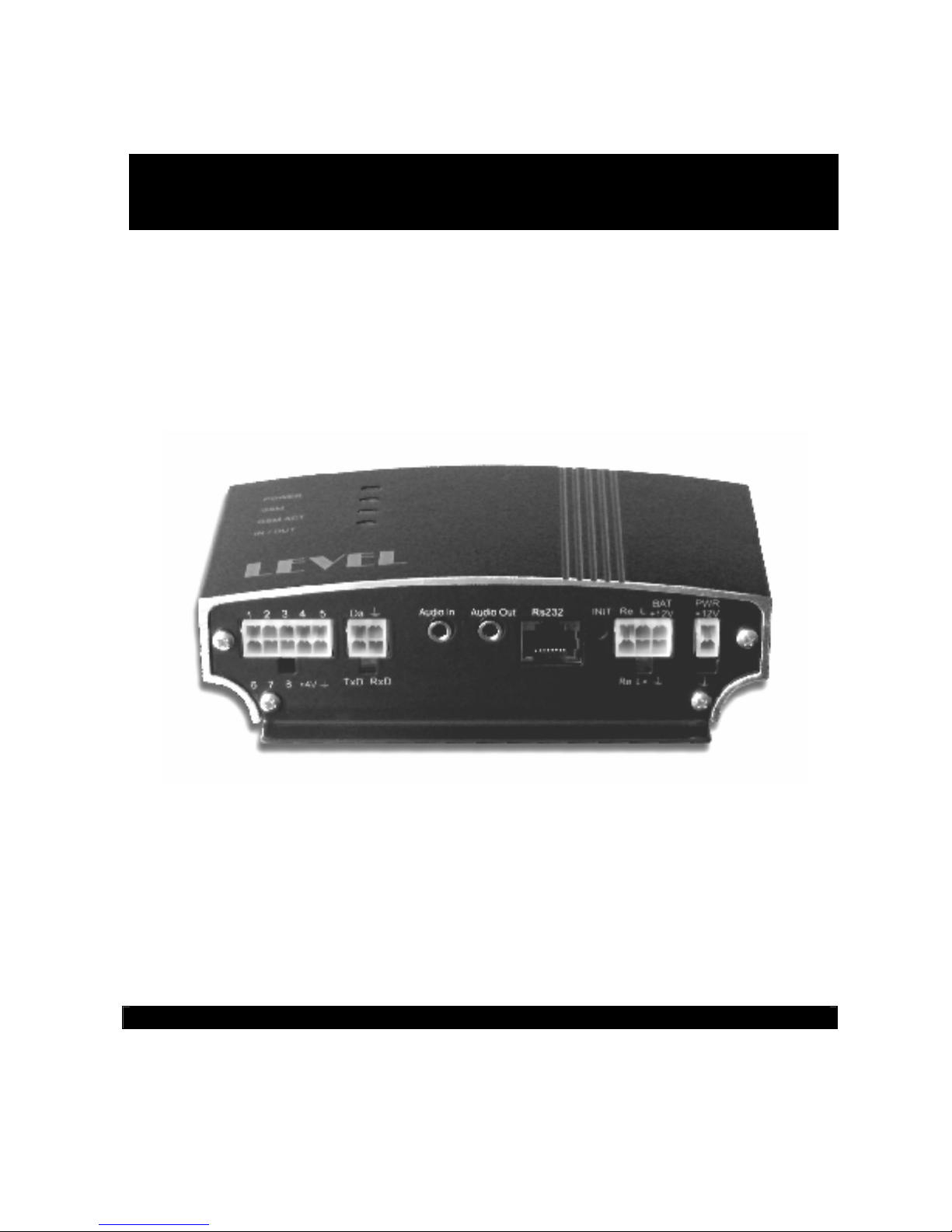
Programmable GSM Automaton
Universal GSM Communicator
Installation and User Guide
LEVEL
GB 060 3xx, GB 060 5xx
Page 2

2
Page 3

3
Dear Customer,
Congratulations on purchasing GB 060. You have purchased a top-quality and stateof-the–art product.
GB 060 combines, in a unique way, a programmable logic automaton with a GSM
communicator fully using advantages and possibilities of mobile networks.
GB 060 will find its use as a highly effective security system for vehicles or real estate
property. Device capable of making alert and sending an alert message to the owner
or control center, providing sound monitoring of the area and possibility of launching
an action as reaction to the situation. When installed in a car or truck, it enables to
track and monitor the stolen vehicle using the transmission of geographical
coordinates to a control center of a security company.
GB 060 can also be used as a security system for different locations that cannot be
easily put out of operation by cutting off the telephone line. This security system is
able to send a warning report within three seconds, to ensure monitoring the room and
space around it and to send geographic coordinates of the secured car continuously.
GB 060 is able to transfer data via GSM, which means that it can function as a
wireless modem for you with your computer as well as a countermodem in a remote
place. By using data transfer, the GB060 device can be controlled from any computer
with a modem.
Dear Customer, for the optimal use of your GB 060, please read this User Guide
carefully. Control of the device is as easy as a little more complicated house
appliance; however, its installation and putting into operation require a good
knowledge of automatic regulation, computer science and telecommunications. For
that reason it is advisable to have the device installed and set to work by a person or
company competent in this field.
LEVEL Ltd.
Page 4

4
Table of Contents:
1. Model range, safety, accessories....................................................................................................5
1.1. GB 060 Models........................................................................................................................5
1.2. Safety Instructions...................................................................................................................5
1.3. Configuration of the GB 060....................................................................................................6
2. GB 060 Instalation, Functional Description.....................................................................................7
2.1. GB 060 - connectors ...............................................................................................................7
2.2. Functional Description.............................................................................................................8
2.2.1. Power Sources................................................................................................................8
2.2.2. Binary Inputs/Outputs.....................................................................................................8
2.2.3. Relay Output...................................................................................................................9
2.2.4. LED Output.....................................................................................................................9
2.2.5. DALLAS Bus.................................................................................................................10
2.2.5.1. Digital Thermometer ED 060 100........................................................................10
2.2.5.2. ID Key Reader ED 060 500.................................................................................10
2.2.5.3. ID Keys.................................................................................................................11
2.2.5.4. External unit of analogue inputs..........................................................................11
2.2.6 RS 232 Serial Connection.............................................................................................11
2.2.7. GPS Antenna ED 002 002............................................................................................12
2.2.7.1. GPS Point.............................................................................................................12
2.2.7.2. GPS Trace............................................................................................................12
2.2.7.3................................................................................................................................12
2.2.8. GSM Antenna ED 001 001, ED 001 002.....................................................................12
2.2.9. SIM Card.......................................................................................................................13
2.2.10. Microphone Connection ED 060 250.........................................................................13
2.2.11. Loudspeaker Output...................................................................................................13
2.2.12. Indication.....................................................................................................................13
3. Setting into Operation and Control................................................................................................14
3.1. Setting into Operation............................................................................................................14
3.2. Initialization and Reset..........................................................................................................14
3.3. Control....................................................................................................................................15
3.3.1. Control from PC Using the RS 232 Interface...............................................................15
3.3.2 Control via GSM.............................................................................................................15
3.3.3. Control via GPRS..........................................................................................................15
3.4. Control and Configuration Using the SMS messages..........................................................16
4. SW Supplied with GB 060.............................................................................................................20
4.1. The GB 060 Control Panel Program.....................................................................................20
4.2. GPS Remote Connector........................................................................................................20
4.3. Remote Connector................................................................................................................20
5. Basic technical parameters:...........................................................................................................20
6. Warranty conditions.......................................................................................................................21
WARRANTY CERTIFICATE.............................................................................................22
Page 5
5
1. Model range, safety, accessories
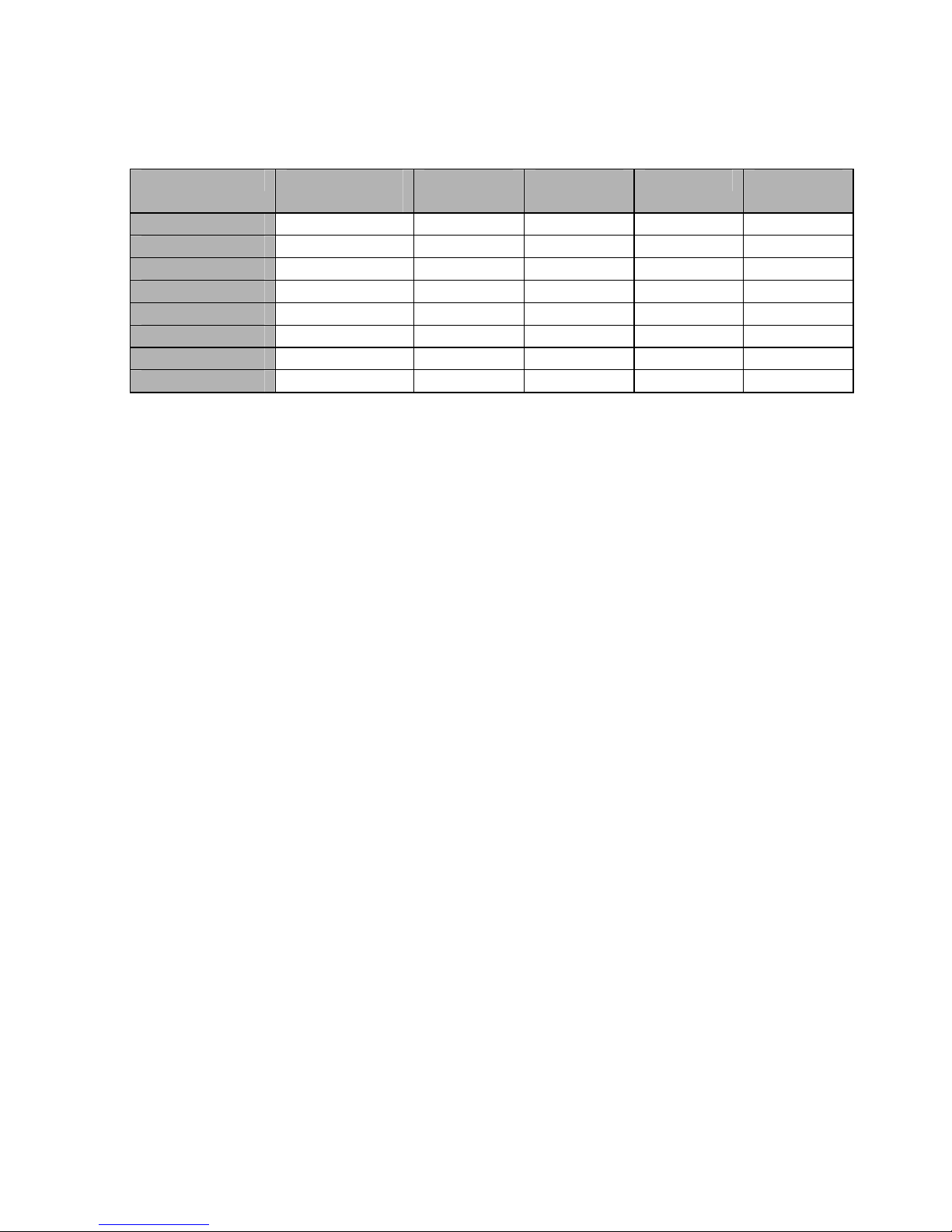
1.1. GB 060 Models
Model name 8× I/O
inputs/outputs
Internal
battery
Dallas
bus
GPS GPRS
GB 060 300
●
GB 060 301
● ●
GB 060 310
●
●
GB 060 311
● ● ●
GB 060 314
●
● ●
GB 060 315
● ● ● ●
GB 060 514
●
● ● ●
GB 060 515
● ● ● ● ●
The letter following the model name (i.e. A,B,C...) then determines accessory range
delivered in the set.
1.2. Safety Instructions
Power Supply. Connect the GB 060 to a permitted power sources only. Such a power
source is the SA 012 503 AC/DC adapter included in the set or alternatively the 12V
power source from a vehicle.
Operational Environment. GB 060 is intended for operation in dry environment
without any aggressive gases or fluids. Do not expose the products to water or
humidity, keep the device off extreme temperatures, do not install the device close to
radiators, open fire or on direct sunshine. Do not expose the device to extreme low
temperatures, e.g. in a car parked outside in winter. Protect from water and other
liquids getting into the device. If this happens, there is a fire risk and the electric shock
hazard. In such a case disconnect the device from the mains.
Maintenance. It is not necessary to open or dismantle the device if operated in the
usual way. Before dismantling the device for any reasons (e.g. inserting a backup
battery) disconnect it from all power sources. During assembly, installation and
operation of the device see to it that the insulation of the of the connecting cables is
intact.
High-Frequency Energy Effects. GB 060 should not be installed or operated in any
rooms or spaces where operation of cellular phones is prohibited. Before installation in
a car, check whether cellular phone operation (and, consequently, the GB 060) is
permitted in your type of car. Installing the GB 060 in places with an increased level of
electromagnetic radiation is not advisable as the reliability of the devise can be
decreased.
Page 6
6
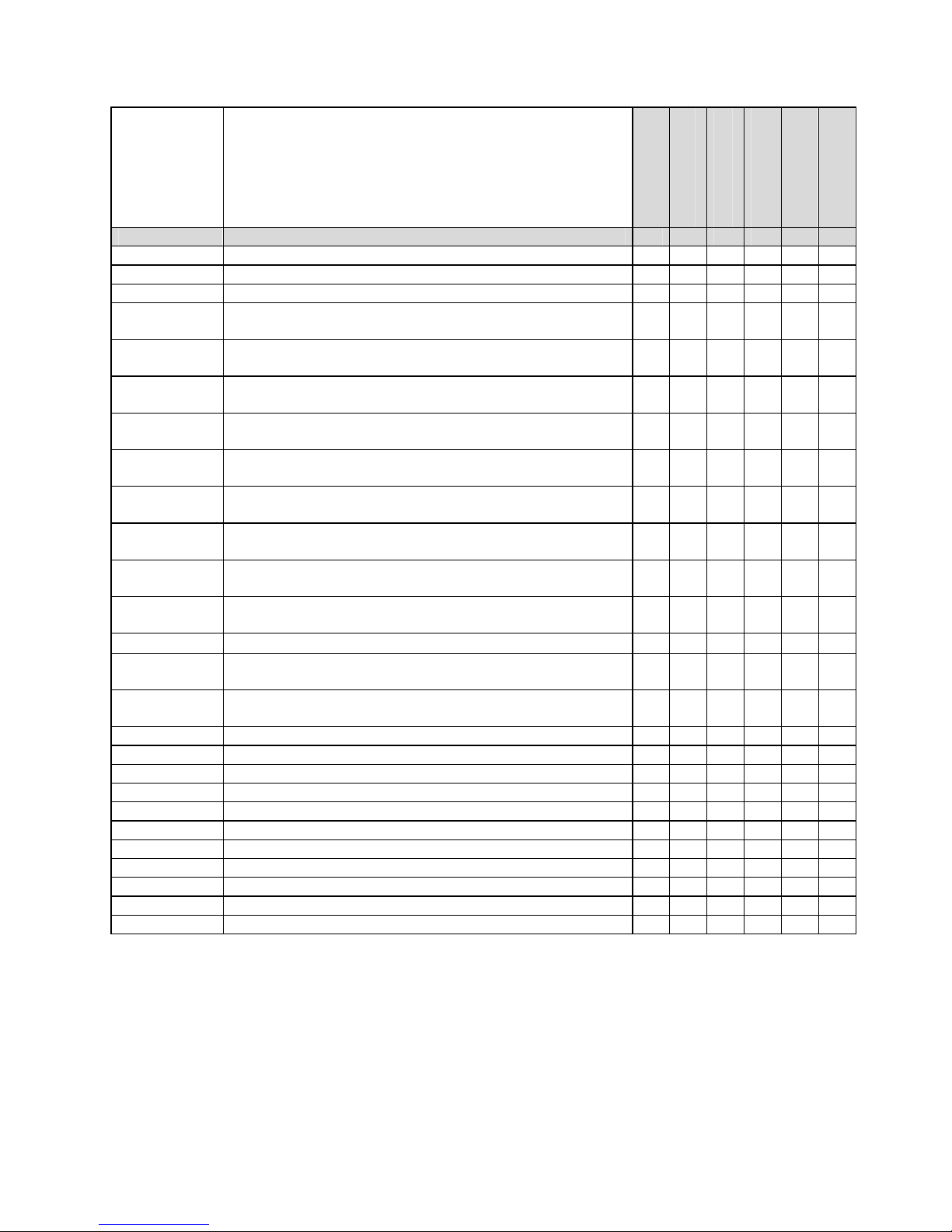
1.3. Configuration of the GB 060
Code Description of components
GB 060 x00A
GB 060 x01A
GB 060 x10A
GB 060 x11A
GB 060 x14A
GB 060 x15A
GB 060 xxx The GB 060 model ● ● ● ● ● ●
ED 001 001 GSM antenna (3dB) ● ● ● ● ○ ○
ED 001 002 GSM antenna – flat, for sticking on glass or plastic ○ ○ ○ ○ ● ●
ED 002 002 GPS antenna active – with SMB connector ─ ─ ─ ─ ● ●
SA 012 603
AC/DC Adapter 220 V/12 V DC, 600 mA, cable 1,5 m,
connector Molex 2pin
● ● ● ● ○ ○
CB 160 021
2-meter-long serial cable with the RJ45 connectors & the
RJ45 /Canon 9 pins reduction piece
● ● ● ● ● ●
CB 161 000
Electro-assembly set: 8 pcs self-cutting grip, 2 pcs cable
connector, 3 pcs binding tape, earth-wire loop
○ ○ ○ ○ ● ●
CB 161 002
2-pin connector, 2 pcs. Of 2-meter-long stranded wire
with a tube into the connector
○ ○ ○ ○ ● ●
CB 161 004
4-pin connector, 4 pcs. Of 2-meter-long stranded wire
with a tube into the connector
─ ─ ● ● ● ●
CB 161 006
6-pin connector, 6 pcs. of 2-meter-long stranded wire
with a tube into the connector
● ● ● ● ● ●
CB 161 011
10-pin connector, 10 pcs. of 2-meter-long stranded wire
with a tube into the connector
● ● ● ● ● ●
CB 161 033
10-pin, 6-pin, 4- pin connectors, 1 piece each, pins
included
○ ○ ○ ○ ○ ○
ED 060 100
Temperature sensor (-25°C to +90°C), Accuracy: 0.5°C,
2-meter-long cable
─ ─ ● ● ○ ○
ED 060 200
External unit of analogue inputs
○ ○ ○ ○ ○ ○
ED 060 250
Microphone with a 1.5-meter-long cable with a connector
(Jack 3,5 mm)
○ ○ ○ ○ ● ●
ED 060 260
Loudspeaker with amplifier for audio output with MUTE
mode
○ ○ ○ ○ ○ ○
ED 060 500 Identifying key reader with a 30 cm long cable ─ ─ ○ ○ ● ●
ED 060 550 Identifying key with an unique code, in a holder ─ ─ ○ ○ ●● ●●
ED 060 600 LED for assembly on a panel, 1,5-meter-long cable ○ ○ ○ ○ ● ●
ED 060 601 Push-button for assembly on a panel, 1,5 m cable ○ ○ ○ ○ ● ●
ED 060 002 Internal back-up battery 9,6 V/600 mAh – 24 hrs. back-up □ + □ + □ +
ED 050 400 Motion detector with keyboard ○ ○ ○ ○ ○ ○
ED 050 300 Double relay output for electrical appliances switching ○ ○ ○ ○ ○ ○
ED 060 602 12 V Sound signalization ○ ○ ○ ○ ○ ○
ED 060 603 Sound signalization with discontinuous tone + LED / 12 V ○ ○ ○ ○ ○ ○
Installation CD with GB 060 Control Panel software ● ● ● ● ● ●
GB 060 Directions for Use ● ● ● ● ● ●
Note: (●) number of accessory pieces included in the set
(○) accessory can be used with the given type of product
(─) accessory cannot be used with the given type of product
(□) accessory can be used only when assembled by manufacturer
(+) accessory installed inside the device already from production
Page 7
7
2. GB 060 Instalation, Functional Description
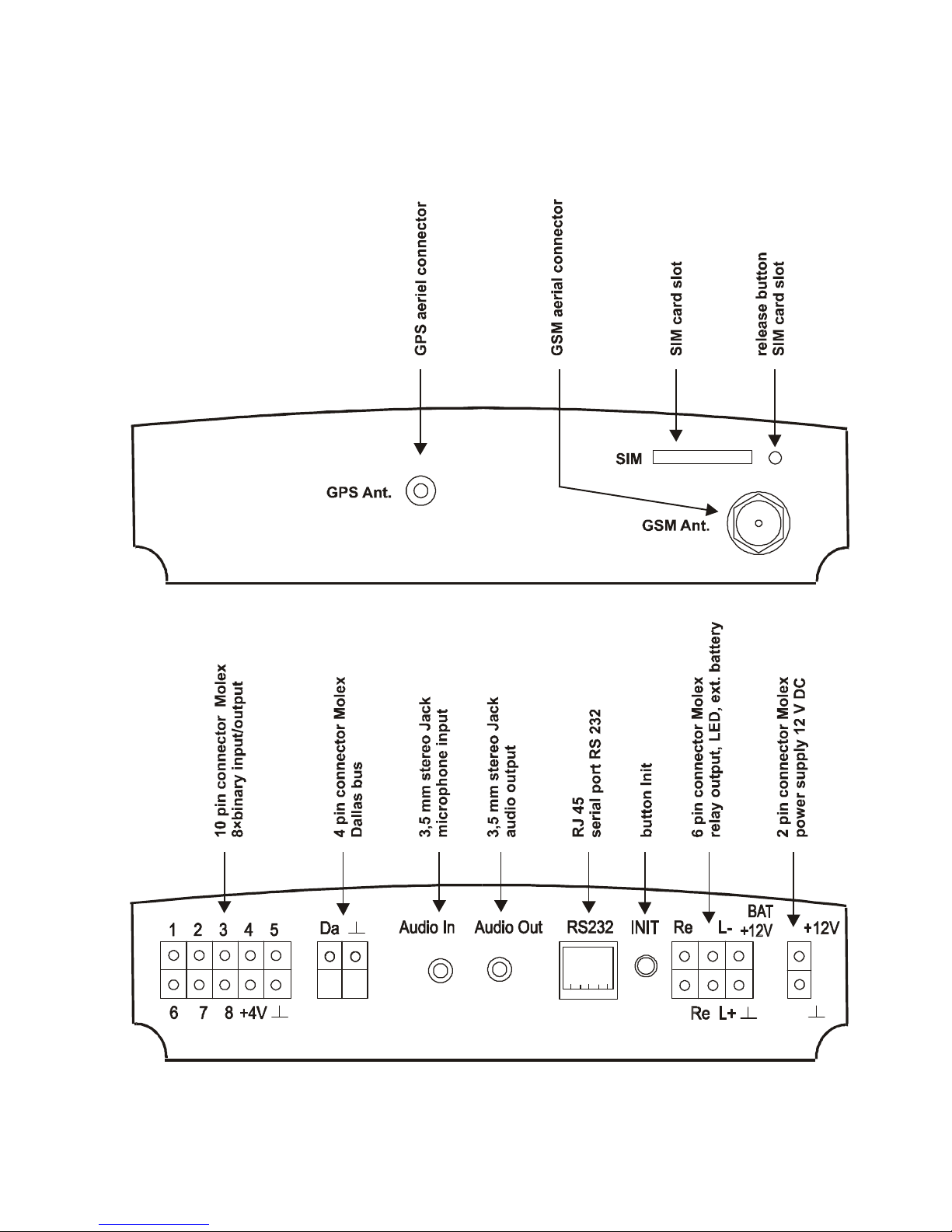
2.1. GB 060 - connectors
Page 8
8
2.2. Functional Description
2.2.1. Power Sources
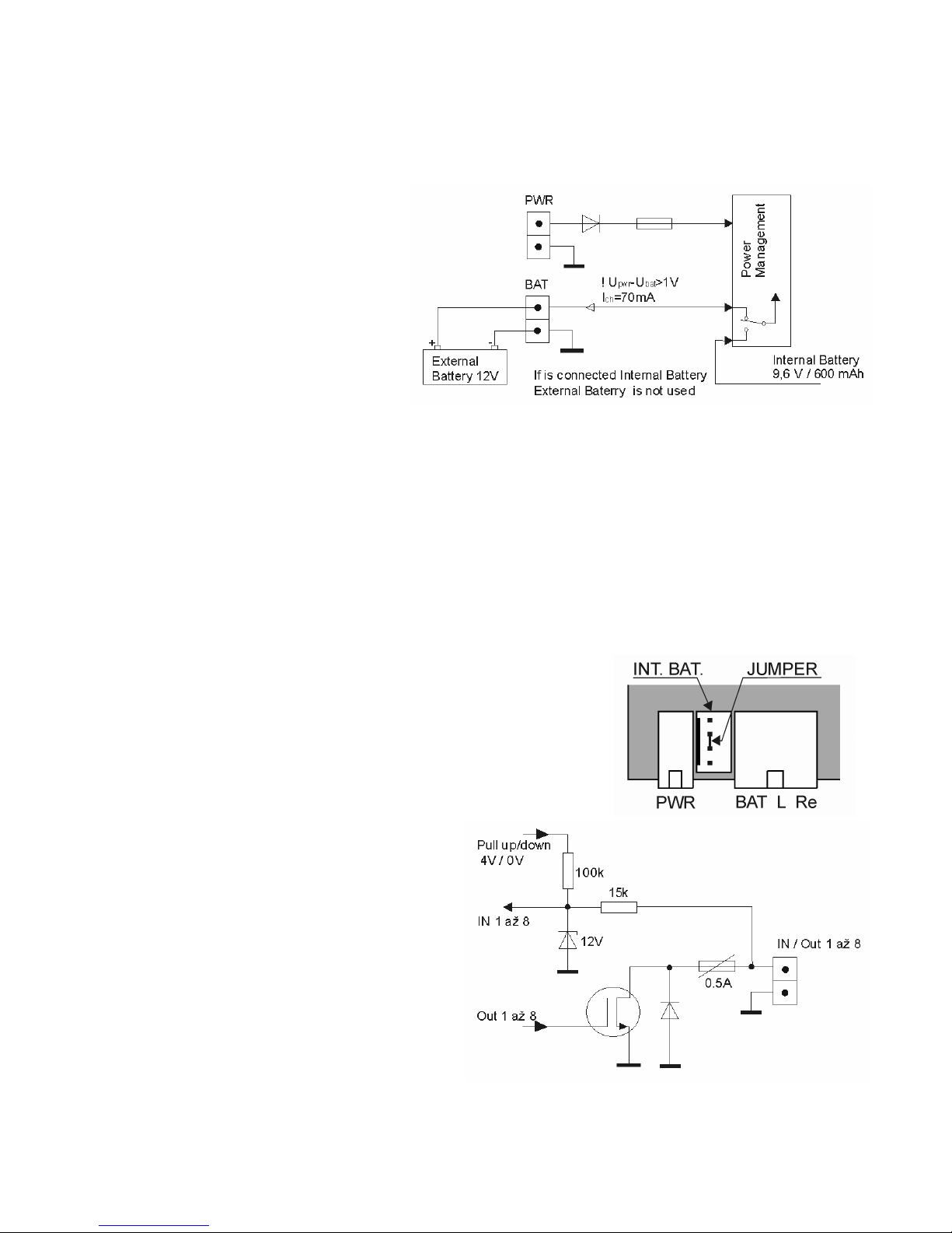
Nominal Voltage 12 V DC (Max. 25 V), Current Max. 0,5 A
Power to the GB 060 unit can
be fed using either the
standard AC/DC adapter
SA 012 503 or the 12 V power
source from vehicle. Power
source must be connected to
the 2-pin power connector
PWR+12 V. In case of power
outage it is possible to use
external battery connected to
the BAT+12 V clip.
Only a 12 V nominal voltage battery can be connected to the device!
The models with internal back up battery 9.6 V / 600 mAh (labeled ED 060 002)
included. In these cases the external battery has no use.
The charging current of internal or external battery is 70 mA while the power source
voltage of GB 060 has to be at least 1 V higher than the battery voltage.
The GB 060 device provides optimal recharging of the internal or external battery.
However, the charging voltage of GB 060 must be at least 1 V higher than the battery
voltage.
NOTE: If you remove internal battery from GB 060 and
want to use external back up battery, it is necessary to
connect interconnecting jumper in the internal back up
battery connector so the two pins in the middle are
connected.
2.2.2. Binary Inputs/Outputs
The device is provided with eight
independently-programmable
inputs/outputs. The signals can reach
two levels only: L (low) or H (high).
The input signals can be information
on the quantities controlled (e.g.
temperature). By the output signals
the quantities can be controlled. The
inputs/outputs are led out to a 10-pin
connector marked with numbers and
a +4V clip and “ground” symbol.
Page 9
9
I/O pin Low (L) High (H)
Load
Carrying
Capacity
Input
Resistance
Input
Max. 0,5 V Min. 3 V, Max. 30 V – Approx. 15
kΩ
Output
Max. 0,3 V Open Collector, Max 50 V
Bias 3,3 V / 115 kΩ
0.5 A –
• A not connected input is on high level (H).
• Output is protected from overcurrent by electronic retracting safety-fuse.
• The +4V clip is intended for power supply of a possible front-end logic. Maximum
load is 150 mA.
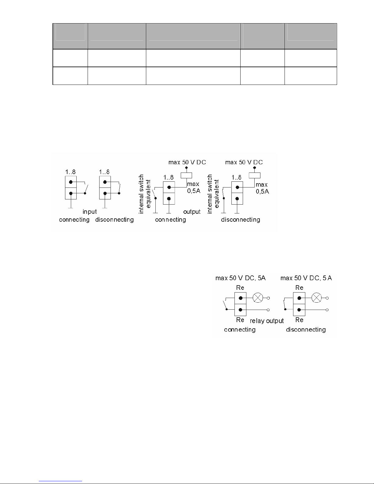
Functions and recommended connection of external input and output circuits:
Binary input/output circuits have to be configured for each required function using the
GB 060 Control Panel software.
2.2.3. Relay Output
The relay output is a galvanically separated
output for direct control of power appliances.
The output is led out to a 6-pin connector
marked with two Re symbols.
The relay output must be configured by the
GB 060 Control Panel software for the
requested action, and then it is possible to:
2.2.4. LED Output
An output for a LED that can be located out of GB 060. The output is led out to a 6-pin
connector marked with the L+ and L symbols.
The LED indicates these states of GB 060:
• the LED is off group 1 is inactive (unlocked)
• blinks each 0.1 sec for a period of 1 sec group 1 is active (locked – basic state)
• blinks twice per 0.1 s for a period of 3 sec group 1 is active, but there is no GSM
signal
Page 10
10
• blinks quickly action in progress – waiting for finishing
action
• LED on for 1 sec action finished
• blinks twice per 1 sec key signing off action in progress
• LED permanently on a phone call or a data call in progress
2.2.5. DALLAS Bus
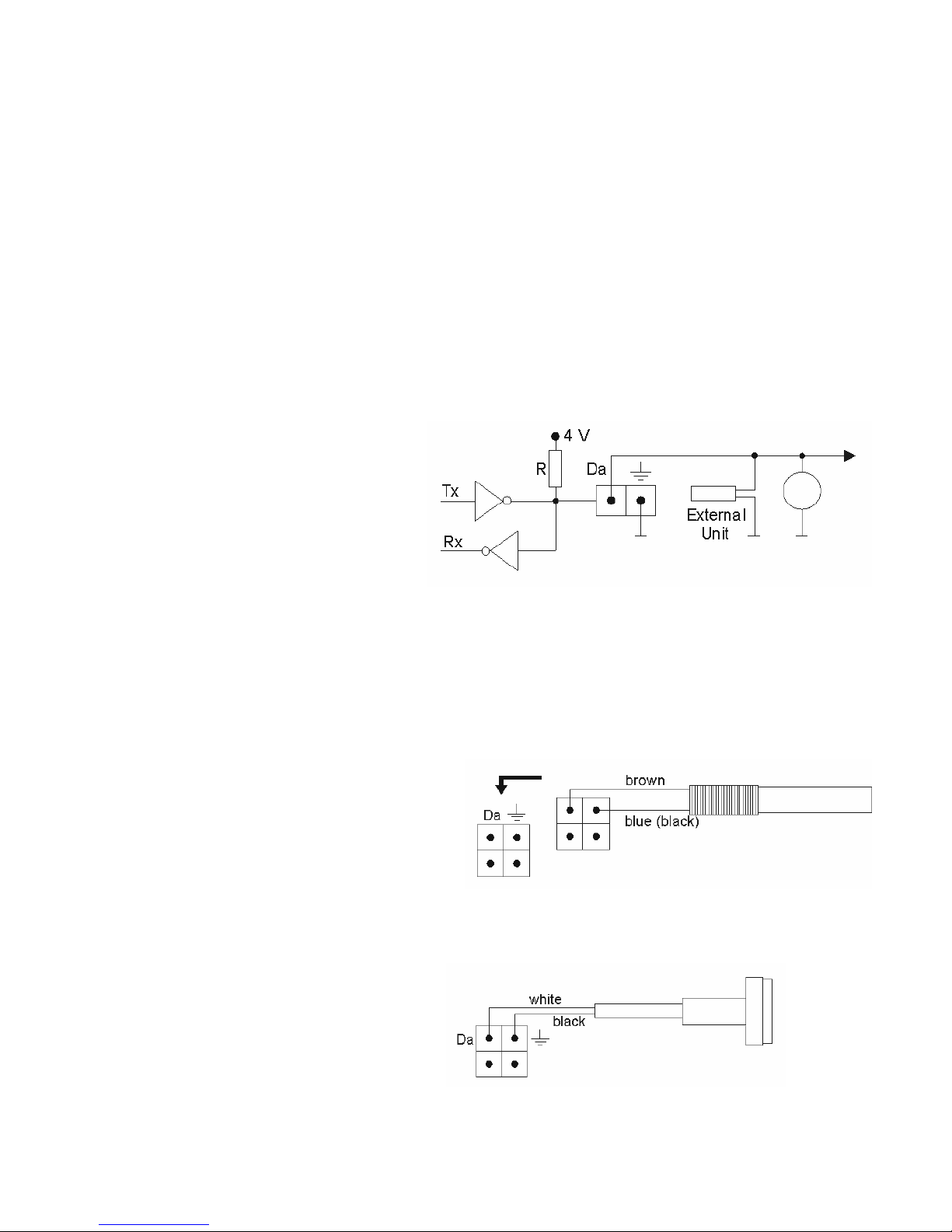
The DALLAS Bus is provided with one master unit and one or more slave units. The
equivalent connection of the slave unit is shown in the diagram, the actual master unit
consists of a processor. Each of the slave units has to have an open-collector or a
three-state output. The common collector resistor (pull-up) is connected on the master
unit side. The DALLAS bus has just one wire to which all the external slave units are
connected. The length of the wire can normally be approx. 100 m. If a telephone cable
with the wires twisted into pairs is used (capacity approx. 30 pF/m), the distance
between the mater unit and the slave unit can be up to 300 meters.
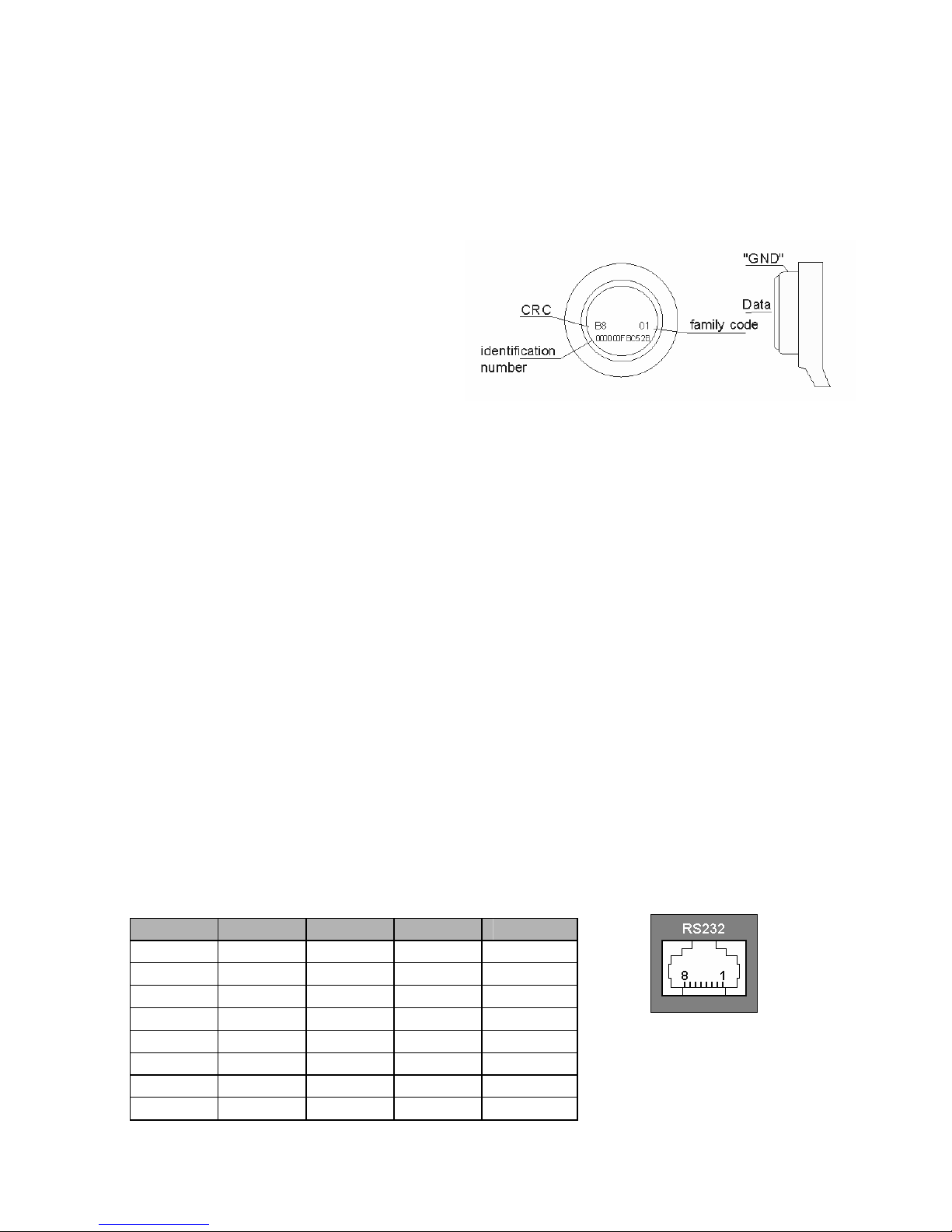
The ID keys have a 16-digit
hexadecimal number marked on
the front side. The thermometers
have the number on an ID tag.
The external units can be added
to GB 060 using the configuration
tools in GB 060 Control Panel
software delivered with the
device.
2.2.5.1. Digital Thermometer ED 060 100
Up to 10 thermometers can be connected to a GB 060 unit at a time.
Temperature data retrieved from the
sensor is treated by the automaton as
an analogue input. An upper limit and
a lower limit can be set up for each
analogue input. An increase of the
analogue value to the upper limit or
lower limit will be interpreted by the
automaton as an event.
2.2.5.2. ID Key Reader ED 060 500
The connection to the GB 060 is
shown in the following diagram:
Page 11
11
2.2.5.3. ID Keys ED 060 550
Each individual identification key is considered an external unit that has to be added to
the system using the GB 060 Control Panel. The GB 060 system can have an
unlimited number of ID keys added.
After putting the key to the ED 060 500 reader, the key ID number is entered into the
GB 060 control unit.
Only one key can be logged in the
system at a time. Log in and log off of
an ID key will be interpreted by the
automaton as an event. Part of an
invoked action (by any event) can
also be a key log off.
2.2.5.4. External unit of analogue inputs ED 060 200
External unit of analogue inputs ED 060 200 contains for inputs – 2 current loops
4-20 mA and 2 voltage loops 0-10 V that enable to connect different kinds of
sensors, for example barometers, humidity meters, water-level indicator etc. Maximum
number of connected analogue inputs and thermometers is 10 while 1 external unit =
4 analogue inputs).
2.2.6 RS 232 Serial Connection
RS 232 is a standard serial channel for communication with a master PC.
RS 232 enables:
- downloading and uploading of the configuration
- reading status of measured values and identification data, entering output values
- reading data recorded in memory – Report
- connecting remote devices with RS 232 interface to a PC using the GSM
connection
- connecting a handheld device / PDA for navigation (GB 060 works as GPS receiver)
- connecting a printer to print incoming SMS messages
Description of signals on the GB 060 side:
Pin Name RS 232 V.24 Direction
1 (CD) CF 109
2 TxD BA 103 =>
3 RxD BB 104 <=
4 (DTR) CD 108.2
5 GND AB 102 ==
6 (DSR) CC 107
7 CTS CB 106 <=
8 RTS CA 105 =>
Page 12

12
Used: 2,3,5,7,8, Connected: 1,4,6
2.2.7. GPS Antenna ED 002 002
GPS antenna ED 002 002 that comes with a 3 meter-long cable gets connected into
the SMB coaxial GPS connector. Its location must be in horizontal position with direct
view of the sky. GSM signal passes through plastic materials and glass but not
through metals and mirror glass. The strength of GPS signal is deteriorated by
weather conditions such as heavy snowing, ice and frost or snow over the GPS
antenna, the GPS signal also gets defused by high buildings or trees.
GPS - Global Positioning System
GPS enables user to determine a position in any place on the planet. It is based on
transmission of signal from satellites that circle in the height of 20 200 km. The basic
condition to read the geographical coordinates is simultaneous reception of signals
from at least four satellites. The accuracy of location is about 15 metres. The system
does not work in tunnels and buildings.
2.2.7.1. GPS Point
Part of the GB 060 configuration can be entering the geographic coordinates
(longitude and latitude) as a center and distance in meters as the circle diameter. The
inner space of such circle is defined as a GPS point. Leaving a GPS point or entering
a GPS point will be interpreted as an event.
2.2.7.2. GPS Trace
Part of the GB 060 configuration can be entering distance that will be defined as a
GPS trace. The GB 060 continuously gathers the geographic coordinates and
calculates the actual distance moved. Moving particular distance in the length of GPS
trace will fulfill one of the two conditions for an action. To prevent the action from being
carried out too often during high speed travel, the second condition can be set as
elapse of a defined time period. To have the GB 060 launch an action, the distance
moved has to be complete traveling of the GPS trace distance or elapsing the
minimum time period.
2.2.7.3. Speed Action
It is possible to define a speed limit GB 060 configuration. Exceeding such limit will
lead to a defined action.
2.2.8. GSM Antenna ED 001 001, ED 001 002
Magnetic GSM antenna ED 001 001 comes with a 3 meter-long cable and connects
into the GSM connector in the upper side of the GB 060 case. Antenna ED 001 002 is
equipped with self-adhesive tape and is designed to be mounted to glass or plastic
material, avoid metal surfaces as they would suppress the GSM signal reception.
GSM Module
Page 13

13
GB 060 includes GSM module which enables two-way connection in the 900/1800
MHz band into a selected GSM network after the log-in procedure of a SIM card
inserted.
It is used mainly for:
• transmitting alert or informational messages and calls from the GB 060 unit
• transmitting control commands to the GB 060 unit in the form of SMS messages
• incoming ringing (free of charge) for remote switching of connected appliances using
a mobile phone
• incoming call for voice transmission using the voice channel
• data connection for reading and changing the configuration, reading status and
reading report file remotely
• sending data packets with current position and device statuses using GPRS
2.2.9. SIM Card
SIM card is inserted into slot next to the GSM antenna connector. To release the slot
press the yellow button next to it. Find a suitable tool for pushing the button, do not try
to open the slot using force. When inserting, put the SIM card in the plastic plate in the
slot and push it inside.
2.2.10. Microphone Connection ED 060 250
The microphone can be connected using the coaxial connectors (Jack 3,5 mm). The
connecting cables can not be longer than 3 meters. Connection of a different
microphone must be consulted with the GB 060 manufacturer.
2.2.11. Loudspeaker Output
For loud communication with the remote device, it is possible to purchase an optional
accessory – high power amplifier ED 060 260. This amplifier has power voltage 12 V
and power output 10 W with loudspeaker load of impedance 8 Ω.
2.2.12. Indication
The front panel is provided with four LEDs to indicate operational states. The list of all
the operational states that can be indicated (signaled) is given in the following table:
When the LED is blinking, the time given before the slash is the light-up, the time
given after the slash is the light-out time.
POWER
• OFF No power source connected
• Permanently ON External power source supply (PWR, paragraph 2.2.1.)
• Blinking 1,2 s / 0,2 s External power source supply, recharging the standby
battery
• Blinking 0,2 s / 1,2 s Standby battery power supply
• Blinking 0,2 s / 0,2 s Standby battery power supply, battery flat
GSM
• OFF GSM module does not work or is not logged in the network
Page 14

14
• Blinking 0,6 s / 0,6 s GSM module is just logging in
• Blinking 0,7 s / 3 s GSM module is logged and works correctly
• Permanently ON indication data connection or call in progress
GSM ACT
• OFF GSM module at rest (no communication takes place)
• Blinking 1 s / 3 s Incoming call ringing indication
• Blinking 0,7 s / 0,7 s Call-connecting-in-progress indication
• Permanently ON Call-connected indication
• Blink once for 1 s Indication SMS sending/receiving
IN / OUT (red)
• OFF No programmable action takes place
• Permanently ON An action in progress
3. Setting into Operation and Control
3.1. Setting into Operation
• Check that the SMS center settings on the SIM card are correct. Insert SIM card in
GB 060. If the SIM card is blocked by PIN, switch it off in a mobile phone first.
• Connect GSM antenna
• Connect GB 060 to serial port of PC
• Connect power source for GB 060
• Install software GB 060 Control Panel from CD
• Run the GB 060 Control Panel and create a configuration – help for using the GB
060 Control Panel can be found using the F1 key.
• Send the configuration into GB 060
The GB 060 unit can be switched off by disconnecting the external power source.
Models with internal battery require pushing the INIT button for a short time after
disconnecting the external power source to prevent discharging of the battery.
3.2. Initialization and Reset
RESET is carried out by pressing the INIT button. Reset is indicated by all four front
panel LEDs on for a period of 0.5 sec followed by all LEDs lighting up one after one.
INIT is carried out by pressing the INIT button for 5 seconds. INIT is indicated by all
LEDs going out. INIT will erase the user configuration of GB 060.
A user configuration can be saved into GB 060 as default configuration that is read
after INIT – for details see the GB 060 Control Panel help.
Such default configuration can also be erased – by pressing the INIT button for
15 seconds. This will be indicated by the LED POWER lighting up.
Page 15

15
3.3. Control
Control of GB 060 – internal configuration settings, switching outputs, reading inputs
statuses and internal variables of device can be done using the following options:
• Using the GB 060 Control Panel software
• Via cable in local connection to serial port in PC
• Via GSM data connection
• Via GPRS data connection
• Using the command SMS messages
• Using ring up of phone number of SIM card in GB 060
3.3.1. Control from PC Using the RS 232 Interface
Serial interface RS 232 (RJ 45 connector) enables using all features of GB 060. For
connection with PC, use the CB 161 020 cable. Install the GB 060 Control Panel
software that will give you very comprehensive summary of the device’s possibilities
including context help for each feature. You can create your own configuration using
the software and send it into GB 060. When connected in on-line mode, you can
check the STATUS window for statuses of GSM, GPS, GB 060 internal variables,
inputs, outputs, etc.
3.3.2 Control via GSM
This connection is made over the GSM data connection. It is recommended to use a
GSM modem. (It is possible to use a mobile phone with data cable to PC or another
GB 060 device as a GSM modem). The SIM cards used in connection must have data
transmissions enabled from the operator. In case of using an analogue modem on
fixed telephone line connecting to GB 060 the SIM card must have a special data call
number activated from operator.
Using this connection, it is possible to do operations with configuration, statuses and
report in GB 060 Control Panel in similar way as in local connection.
3.3.3. Control via GPRS
Use the GPRS internet access via network access point (APN) from your operator.
The SIM card in GB 060 must have GPRS transmissions enabled.
GPRS Data Connection Using the UDP Protocol
PC that will be initiating the connection must have public IP address. Action in GB 060
will launch a call to selected number from phone directory that represents the required
GPRS connection. GB 060 will connect to the internet and make the required
connection. This connection will be set to the public IP address of the PC and selected
UDP port. GB 060 Control Panel must be switched to mode “Wait for connection”.
Page 16

16
GPRS Data Connection Using the TCP Protocol
To use this connection, the access to relevant proxy server must be provided. Action
in GB 060 will launch a call to selected number from phone directory that represents
the required GPRS connection. GB 060 will connect to the internet and make the
required connection. This connection will be set to the public IP address of the proxy
server and selected UDP port. GB 060 Control Panel willl then connect with the proxy
server on selected TCP port using the TCP protocol and log in using the defined user
name and password. The proxy server will provide connection between the Control
Panel and the remote GB 060.
3.4. Control and Configuration Using the SMS messages
It is possible to configure, control and remotely read values from GB 060 using SMS
messages.
Structure of Command SMS
Command SMS structure
Command SMS always begins with current PIN of GB060, followed by space and key
word or the inquiry or command (in Table of SMS commands the key words are
marked by capital letters). Before key word there can be name of object or name of
command - separated by dots. Key word is followed by command value or question
mark for an inquiry. One SMS can contain more commands or queries, they must be
separated by a space. The number of commands or queries in one command
message is only limited by the length of SMS - 160 characters.
Example of command SMS: 1234 POWER GPS TACHO 155
1234 - access PIN of GB 060
POWER – power supply status query
GPS – position query
TACHO 155 – setting the speed indicator to value 155
Page 17
17
Basic Command SMS
PIN - GB 060 access PIN
pin PIN x x=? - query, x=new PIN – change PIN
SW, HW version, GB 060 serial number
pin PRODUCT
Communication adapter SW, HW version, serial number (if installed)
pin ADAPTER
Power supply status, internal battery, charging
pin POWER
GB 060 reset
pin RESET
GB 060 initialization
pin INIT
GB 060 RS 232 settings
pin COM x y x=? - query,
x= baud rate (1200, 2400, 4800, 9600, 19200)
y= data flow control, y=1 - enabled, y=0 – disabled
GB 060 time settings
pin RTC x x=? - query, x= dd-mm-rr hh:mm:ss
ID key query
pin KEY
Change of number in phone directory
pin name_of_phone_no. x x=? - query, x= new phone number in international
format
SMS commands for GSM
GSM operator query, credit value, BTS cell ID, GSM signal value
pin GSM (signal value is in range 0-32, 0=min.)
Credit query
pin CREDIT
Settings of credit query
pin CREDITMODE x x=? - query, x=0 - do not read, x=1 - read from
SIM,
x=2 - read using USSD code
USSD code for credit query settings
pin CREDITCMD x x=? - query, x= USSD code, (i.e. in CZ: T-mobile:
*101#, Oskar: *22#, Eurotel: *104*#)
Credit value low limit
pin CREDITLOW x x=? - query, x= credit value
Page 18

18
SMS commands for GPS
Abbreviations: jgpsb= GPS point name, jgpst= GPS trace name
Position query
pin GPS Example of reply: GPS 50 25.220300 N 16
10.078100 E = 50° 25,2203' north 16° 10,0781'
east
Position query - decimal reply
pin GPSD Example of reply: GPSD 50.420261 N 16.167929 E
= 50,420261° north 16,167929° east
Position query - reply using GGA NMEA sentence
pin GGA
Position query - reply using RMC NMEA sentence
pin RMC
GPS speed indicator query
pin TACHO x without x - query, x= value - new value of speed
indicator
Speed query
pin SPEED
GPS point diameter settings
pin jgpsb.LEN x x=? - query, x= value in [m]
GPS trace distance settings
pin jgpst.LEN x x=? - query, x= value in [m]
GPS trace time period limit settings
pin jgpst.INTERVAL x x=? - query, x= value in [min]
SMS commands for binary inputs / outputs
Query on list and statuses of binary inputs
pin INS
Query on list and statuses of binary outputs
pin OUTS
Output settings
pin output_name x x=? - query, x=0 - set output value to log. 0
x=1 - set output value to log. 1
Relay output settings - operation mode
pin output_name.MODE x x=? - query, x=0 - disabled, x=1 active in log. 0,
x=2 active in log. 1
Relay output settings - pulse length
pin output_name.DELAY x x=? - query, x=0 - no pulse, x= value 1-255 [s]
Counter query and settings
pin output_name.COUNTER x x=? - query, x= value - new counter value settings
Page 19
19
SMS command for actions
Launching an action
pin action_name Reply: action_name.run
Enabling action
pin action_name.ENABLE x x=? - query, x=0 - disabled, x=1 - enabled
Adding an action into group
pin action_name.GROUP x x=? - query, x=0 - group 1 ... x=7 - group 8
SMS commands for analogue inputs
Query on list and statuses of all analogue inputs
pin AINS
Query on status of analogue input
pin an.input_name
Delay before action settings
pin an.input_name.DELAY x x=? - query, x= value in [s]
Low limit settings
pin an.input_name.LOW x x=? - query, x= new low limit value
High limit settings
pin an.input_name.HIGH x x=? - query, x= new high limit value
SMS commands for calling
Audio input settings
pin AUDIOIN x x=? - query, x=value 0-100, 0= min. 100= max.
Audio output settings
pin AUDIOOUT x x=? - query, x=value 0-100, 0= min. 100= max.
Call back with listening-in
pin CALLBACK (calls back to the SMS sender)
Voice call to defined number with listening-in
pin CALLV x x= called phone number
Data call to defined number with connection to RS 232
pin CALLM x x= called phone number
Data call to defined number with connection into configuration
pin CALLR x x= called phone number
SMS commands for timers and action planners
Abbreviations: nt= name of timer, nap= name of action planner
Time period settings
pin nt.PERIOD x x=? - query, x= time value in [s/10]
Enable action planner
pin nap.ENABLE x x=? - query, x=0 - disable, x=1 - enable
Page 20

20
4. SW Supplied with GB 060
4.1. The GB 060 Control Panel Program
Part of the GB 060 software installation is the GB 060 Control Panel software, which
serves as a primary tool for the device configuration and for detection of the device's
operational state including the state of all its inputs. The program connects to the
device through either data connection via the local serial interface or through the GSM
network using a PC-connected modem. This program includes an electronic help
system with detailed explanation of the configuration procedure. This program works
under MS Windows 98/2000/Me/XP
4.2. GPS Remote Connector
Installation CD contains GPS Remote Connector software that provides transmission
of GPS coordinates from remote GB 060 units to PC. GPS coordinates are transmitted
using the virtual serial port to special map software (i.e. Autoroute, Route66,
Mappoint) to display the current position on the map. The software works under
Windows 2000/NT/XP operation systems.
4.3. Remote Connector
Part of the installation CD is also Remote Connector software that enables to create a
bridge connection over the RS 232 serial interface from a remote GB 060 unit to your
PC. Data from the remote GB 060 can be then transferred over the GSM network to
the Virtual COM port in your PC and can be then used by any application. It is
recommended to use another GB 060 unit on the PC side however other GSM modem
can also be used. Before you run the Remote Connector, you have to install the virtual
COM port by installing new hardware in the Windows Control Panel; description of
how to do it is listed in the Readme.txt file.
5. Basic technical parameters:
Dimensions width × height × depth 144 × 44 × 88 mm
Nominal supply voltage 12 V DC
Power consumption in standby mode less than 20 mA
Maximal power input 0,5 A at 12 V
GSM 900 / 1800
Switches 1-8 current max. 0,5 A
Relay current max. 5 A
REPORT memory capacity about 3000 GPS records**,
extensible up to 12000
Operation temperature range for GSM module -25 °C to +65 °C*
Operation temperature range for other parts -40 °C to +85 °C
Page 21

21
* When outside this range the GSM connection could be restricted or completely out of
service
** The GPS coordinates must be entered into the Report file in binary format
GPS_BIN POS
6. Warranty conditions
The warranty period is 24 months from the date of sale and applies solely to the goods
registered or marked by LEVEL.
Warranty repair will be made within ten working days from the date of delivery of the
defective goods to LEVEL provided that the respective spare part is in stock.
Otherwise the user will be offered an alternative solution until the repair is completed.
Warranty repairs shall be carried out in the LEVEL company and the warranty period
will be extended accordingly. The manner of repair shall solely be decided by the
service engineer.
Warranty will not be provided in case of loss or confusion of the warranty certificate,
damages to the product caused acts of God, damages caused during transportation,
by improper placing or operation, operating the device in unsuitable conditions and in
case of removing or damaging the sealing labels.
The warranty does not apply to consumption materials, e.g. floppy disks, ribbons, etc.
or to any malfunction caused by the software installed or software interaction. LEVEL
is not responsible for any loss the customer may incur as a consequence of a defect
of the device.
The warranty does not apply to the device not functioning due to external conditions
such as changes in the legislature, changes in the telephone or power-supply network
etc.
The warranty should be claimed by submitting fully filled-in warranty certificate and the
device to be repaired including its accessories.
No copies of the warranty certificates available. The customer is responsible for its
correctness and originality.
Page 22
22
WARRANTY CERTIFICATE
Product Name:
Model:
Serial Number: Date of Sale: Signature:
Selling Organization:
Address, Telephone, Stamp:
Received for
Repair
Shipment
Date
Fault Description
Page 23

23
Page 24

24
GB [email protected] © LEVEL, 2005
LEVEL Ltd., Plhovská 1997, Náchod 547 01, CZECH REPUBLIC
E-mail: [email protected]
www.levelna.cz
 Loading...