

Page 1
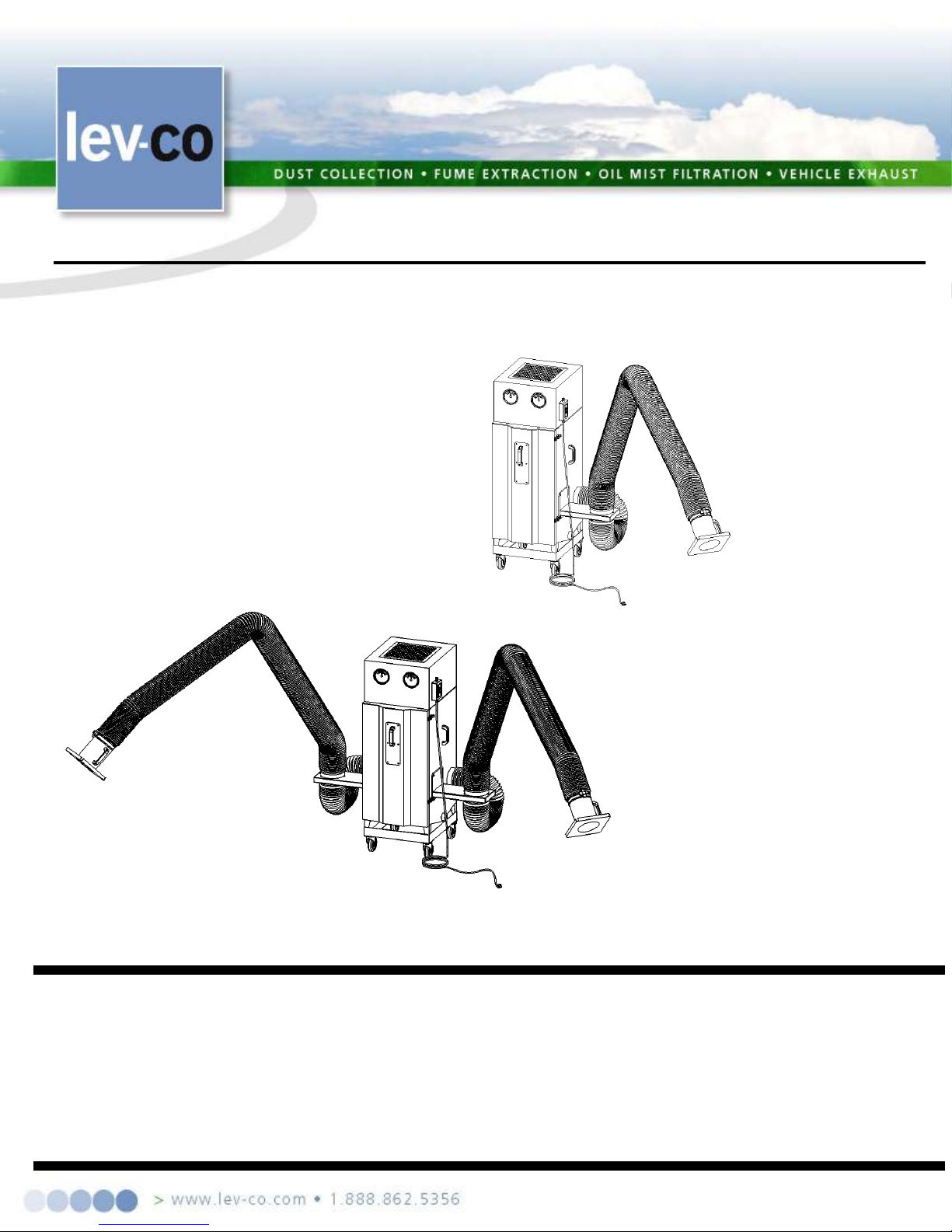
OWNER’S MANUAL
MODEL
MULTI
-
FLEX
•
INTRODUCTION
***IMPORTANT***
ANT.
A
•
SPECIFICATIONS
• UNPACKING
• INSTALLATION
• ELECTRICAL
• OPERATION
• MAINTENANCE
• TROUBLESHOOTING
• REPLACEMENT PARTS
• MOTOR TROUBLE GUIDE
THIS MANUAL CONTAINS PRECAUTIONARY STATEMENTS RELATING TO WORKER SAFETY. READ AND SAVE
THIS MANUAL COMPLETELY AND COMPLY AS DIRECTED. ALL THE POTENTIAL HAZARDS OF DUST AND MIST
CONTROL SYSTEMS AND EQUIPMENT ARE IMPOSSIBLE TO LIST; THEREFORE, OBTAIN THE SERVICES OF A
PROFESSIONAL INSTALLER.
PRODUCT IS INTENDED FOR USES WHICH PRESENT A POTENTIAL RISK OF FIRE OR FIRE PROPAGATION. REFER
TO APPROPRIATE AUTHORITIES, AND DISCUSS YOUR INTENDED USE WITH A LEV-CO REPRESENT
WORKERS HANDLING EQUIPMENT OR SYSTEMS SHOULD BE INSTRUCTED TO CONDUCT THEMSELVES IN
SAFE MANNER.
A FIRE PROTECTION EXPERT SHOULD BE OBTAINED IN THE EVENT THE
Page: 1/15 .
Page 2

ALWAYS USE
LEV-CO REP
L
ACEM
ENT
PAR
T
S AND FI
LTERS TO MAINTAIN
WARRANTY.
TO ORD
E
R SPARE
P
ARTS:
CO
NTA
C
T US:
1050 BROCK ROAD, Unit 22
-24
Phon
e 905.831.7001 or 888.862.5356
E-m
ail:
sales@lev
-co.com
Website: http://www.lev
-
co.com
Pickering, ON, CANADA L1W 3X4
Fax: 905.831.7443 or 866.840.9923
Page: 2/15 .
Page 3
REA
D INSTRUCTION
S CAREFULL
Y B
EFOR
E ATTEMPTIN
G TO IN
STALL
, OPERAT
E OR
SERVICE
YOUR MODEL MINI-VAC UNIT. RETAIN THESE INSTRUCTIONS FOR FUTURE REFERENCE.
Page: 3/15 .
Page 4

SAFETY RULES
Follow all electrica
l and
safety code
s as well as the
National
Elec
tric Code (NEC)
, National Fire Pr
otect
ion
Association (NFPA), and the Occupational Safety and Health Act (OSHA). All electrical connections and
wiring
n
o
found
GENERA
L OPERA
T
IONA
L WARNING
1. Do not mix material
s being
collected by a
dust
collecto
r unles
s it is determine
d that mi
xing of material
s does
not
caus
e hazardou
s condition
s to
occu
r or
creates a
conditio
n of
operatio
n for which the
equipmen
t was not intended.
2. Unde
r no
condit
ion should bur
ning ci
garet
tes or any
burn
ing objec
t be
allow
ed into the hood or ducting of any
dust control
system.
3. When dust
collec
tors are
used to collect em
issions from steel or combin
ed metal sanding, the
dust
collec
tor
should be
locate
d an adequate dis
tance away to minimize the
chanc
e of
ignitio
n of
duct sy
stem
residue from hot metal
dust
nt
4. Al
ways disconnect unit from
power
s
ource before inspecting or servicing.
LEV
-
CO
S
ETS THE
STANDARD
The Lev-co MULTI
-
FLEX
collects
dust,
welding smoke,
mist and other
atm
ospheric pollutants in industrial
1.
Mist/vapor control package which consists of a 2” i
m
ping
e
ment pre
-
filter or a 4" Chevro
n
pre-filter.
charcoal
modules (total of 50# charcoal
- no
t included) and a 1" poly after
-
filter.
3. High
eff
iciency
colle
c
tion package
consisting
of a 2"
aluminum
pre-f
ilter,
a
12" 95%
bag f
ilter and a 99%
DOP or 99.
97% HEPA f
i
lter.
otor
should be performed by qualified personnel only.
National Fire Protection Association (NFPA) standards require specific duct design and dust collector configuratio
when collecting potentially reactive metal dusts, such as aluminum and magnesium, and other materials. NFPA als
covers other dusts such as grain, plastics, etc. A guideline for determining the precautions to be taken can be
thru NFPA. Consult current NFPA standards, available from NFPA, 1 Batterymarch Park, Quincy, MA, 02269, 1-800344-3555, for applicable safeguards which may required for the Installation, Operation, and Service of this product.
Fire suppression equipment provided by others.
Additional references are the Uniform Building Code and Uniform Mechanical Code.
chips and sparks. Should further protection from fire be required, adequate duct systems from capture hoods and
collector should be provided so that a fire protection specialist can install extinguishing equipment. You may also wa
to contact your insurance underwriter.
plants, shops, schools and factories. The MULTI-FLEX is available in multiple configurations each specific for the
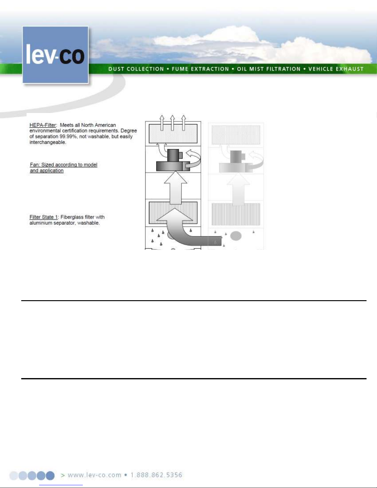
type of pollutant requiring capture. The general theory of operation ( for the standard configuration unit ) is that air
bearing pollutants passes through the inlet section into the dust pan located in the plenum section where large
particles and sparks fall out of the air stream. The particulate laden air then makes a 180o turn to pass through the 2"
30% aluminum mesh pre-filter. A second dust tray is located in this section as well. Once passing through the
aluminum pre-filter, the air is drawn through the main 95% bag filter where the +1 and sub-micron particles are
captured. This main filter has 88 ft2 collection area for maximum intervals between service. An optional shaker
handle is available for dry dust applications.
Optional filter arrangements for special conditions are as follows:
2.
Odor control package which uses a 12" deep 95% bag (36 ft2) followed by two refillable Adsorption
The particulate laden air is drawn through the filter section. The high static pressure blower and m
discharges the clean air into a built-in silencer for maximum noise reduction.
Page: 4/15 .
Page 5
The MULTI
-
FLEX
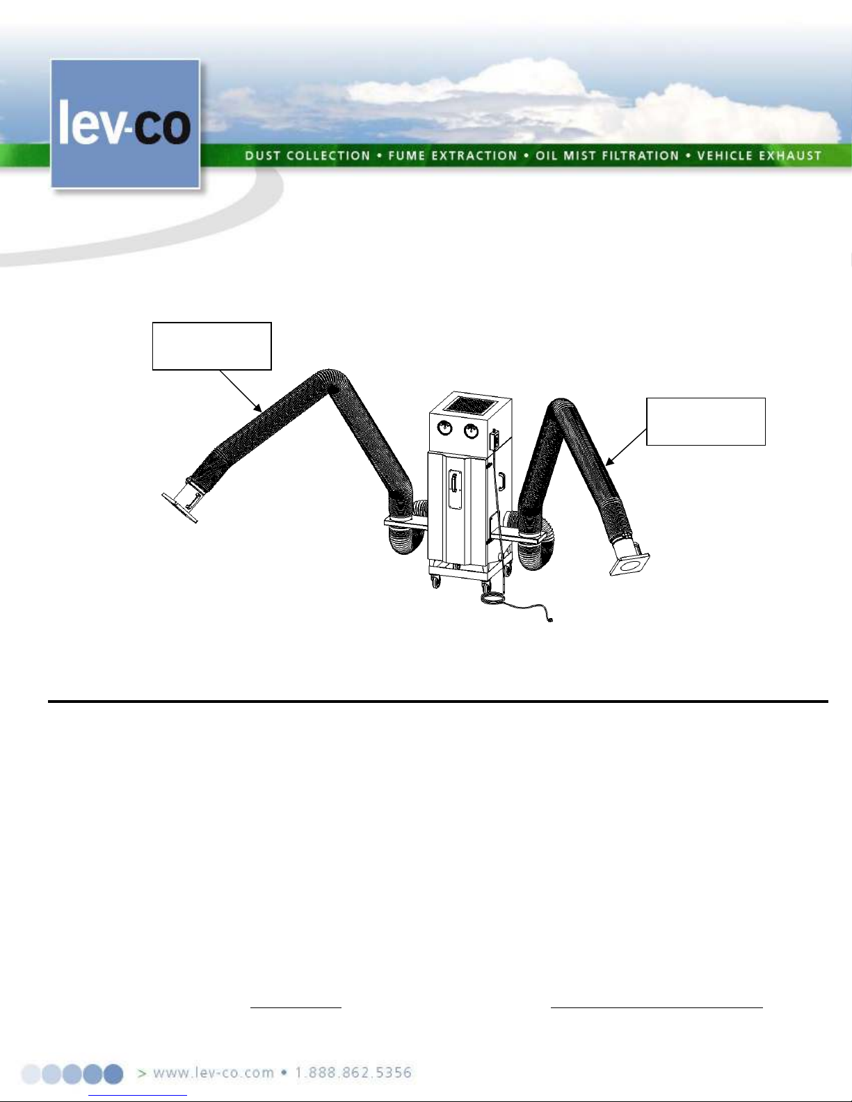
is a complete portable
or
stationary
collector.
The unit comes equipped
with
four 5"
industrial duty casters (2 swivel, 2 fixed). It comes standard with a single 8" diameter, 10' long (or optional dual 8"
Figure 1.
SPECIFICATIONS(*):
MULTI
-
FLEX
STD DIM:
27
" W x 76" H x 50.5
" D [1.02m W x 1.67m H x 0.66m
D]
paint.
Includes
side access
doors,
dust
pan door,
5"
casters,
self supporting
6.75"
dia by
10' long
extractor
arm,
and
NOISE LEVEL:
STD
78 dBA @ 5
'
, 68 dBA @ 5'
with optional silencer
1.5 HP, 115/208
-
230/1/60 @ 17.0/8.5 A
Dual
Arm Option:
switch; others ter
m
inated
at J-box on unit exterior
STANDA
RD
OPTIONAL (vario
u
s available)
1st Stage:
12” 95% Main filter
STANDARD
OPTIONAL
diameter 10' long) Internally supported arms for at-the-source capture of pollutants. Optional 7’ and 13’ long
arms are available.
2-nd arm
1-st arm
WEIGHT:
CONSTRUCTION:
197 lb. (STD)
16 gauge welded zinc coated steel cabinet, finished with a two part chemical and oil resistant
ULTRA-SEAL filter sealing system to prevent by-pass.
ELECTRICAL:
Standard Motor:
Opt: 1.5 HP, 208-230/460/3/60 @ 4.9-4.6/2.3 A
Opt: 3 HP, HP 208-230/460/575/3/60 @ 8.0/4.0 A
STD 2 HP 208-230/460/575/3/60 @ 5.7-5.4/2.7 A * 1.5 HP 115V AC wired with cord and
BLOWER: Direct drive radial blower
FILTRATION:
12” 95% main filter
2nd Stage:
12" 99% main filter
2 – 12” AD/Carbon filter modules
Page: 5/15 .
Page 6
3rd Stag
e: Optional 12”
HEPA filer
Optional 12” Hepa Filter
Figure 2.
INSPECT
I
ON AND UNPACKING
Inspec
t your
LEV
-CO unit for shipping damage immediately
upon re
ceipt
, save all packaging material
s until
t
the
ms
Y
ilter and
PRE
P
ARATION AND INSTAL
LATION
After initial
inspe
c
tion for
shipping
dam
age, open
the cabinet
and motor
access
door.
Rem
ove all
packing
l
nd electrical codes required for the unit. Authorities having jurisdiction should
National
If
Table
re
panied
(*) Lev-co has a policy of continuous research and improvement, and reserves the right to change design and specifications without notice.
unit has been received, inspected and accepted.. Damaged carton(s), broken crate(s), etc. are indications that the uni
may have been damaged in shipment. It is also possible shipping damage may be concealed and not noticed until
unit is installed and in operation. If any damage is found, notify your delivery carrier at once and enter a claim. Clai
must be filed within 24 hrs of receipt of shipment. FREIGHT DAMAGE CLAIMS ARE THE RESPONSIBILIT
OF THE PURCHASER, NOT LEV-CO. After initial inspection for shipping damage, check the cabinet f
motor/blower compartments for any packing materials and remove.
materials and filters to avoid damage and to facilitate the installation. The installation should conform to all loca
ordinances associated with building a
be consulted before installation is made. If there are no local codes, the installation should conform to the
Electrical Code. The MULTI-FLEX can be used as either a roll-around portable unit, wall mounted or suspended.
using an extension cord with the portable unit refer to the Appendix, Motor Troubleshooting Guide,
A for the correct wire gauge. The following section discusses both physical installation and electrical tie-in. Fi
suppression equipment provided by others. If an optional light kit was ordered, this manual will be accom
by a Light Kit Manual with an instruction sheet for light kit service and operation.
Page: 6/15 .
Page 7
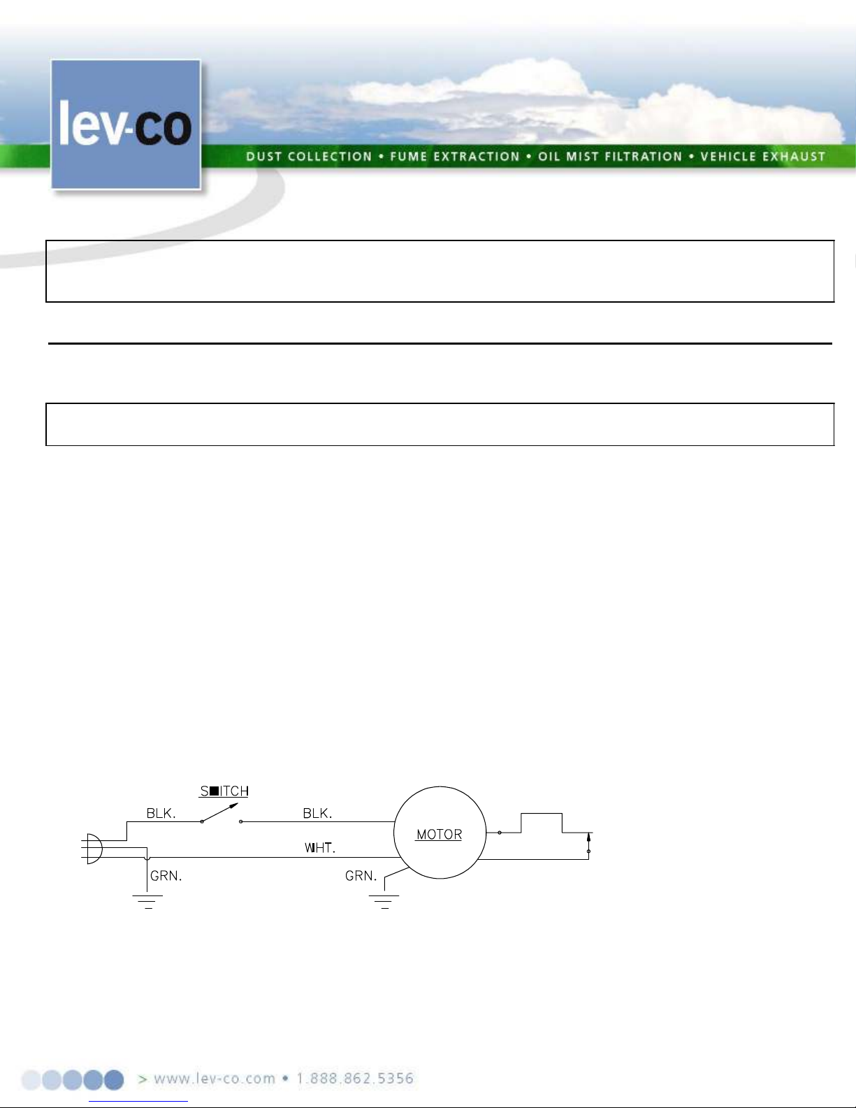
CAUTION
ELECTR
I
CAL
CAUTION
The MULTI
-
FLEX
is
equipped
with
a
side mounted
junction
box.
All 115V
AC
units
have
an
ON/OFF
ters and disconnects are not
Motors
box
have
.
meplate rating. These specifications can be
wiring
Figure 3.
WHEN USING THE MULTI-FLEX IN THE PORTABLE CONFIGURATION, DO NOT OVER EXTEND
THE POWER CORD REACH. DISCONNECTING THE POWER SOURCE WHILE UNIT IS IN
OPERATION CAN CAUSE SPARKING.
CABINET DOORS MUST BE CLOSED WHEN RUNNING BLOWER. MOTOR WILL BE
OVERLOADED IF RUNNING WITH DOORS OPEN.
switch and
cord with plug. Three phase units have wiring terminated inside junction box; motor star
supplied with the unit (unless purchased as an option), and must meet local and National Electrical Code.
are typically multiple voltage type (e.g. 115/230 or 208/230/480). Make sure connections in motor junction
correspond to the line voltage you plan to use. Three phase motor starters (manual or magnetic type) must
properly sized thermal overloads for the voltage and current required at the motors.
Motor checkout should be performed with the unit running, all filters in place and cabinet doors closed
Measured motor current readings should be equal to or below motor na
found on the motor name plate or in the specifications section of this manual.
The single phase 115V AC motors supplied in the MULTI-FLEX have thermal overload protection.
Motor rotation may be changed, if required, by reversing two internal motor leads located under the
cover. The motor cover plate shows an internal schematic of the motor and should be consulted for this operation.
Page: 7/15 .
Page 8

THREE
PHASE
MOTORS
Three
phase motors
do
not have
overload
protection
in
cluded
in
the standard
configuration
and m
ust be
supplied by the end user. They are also available from the factory as a pre-installed option. If these
protective
other
On the three
phase
mo
dels,
the motor
can operate
in
either direction.
However,
for proper
suction
and
Figure 4.
s
hows
details
on
changing
the wiring
configurations.
The m
ain power
tor rotation
s
the
Figure 5.
CAUTION
OTH
E
R OPTIONS
- EL
ECTRI
CAL
The standard
Light
Kit will require
an
additional
4.0 A at 1
15V
AC minimum, be sure to add this into the
only
switching
MAINTENANCE
OR
T
TO ANOTHER, YOU MAY BE
RUN
ED TO
circuits are not ordered from the factory, use equipment as specified by the National Electric Code or
applicable authority.
airflow, the blower motor should be turning in a Centrifugal direction when viewed
from the top of the unit. To verify the correct rotation, open the blower access
panel and bump start motor (turn on briefly then turn off). Look at the top of motor,
using an inspection mirror if necessary, and make sure the motor is turning
clockwise as illustrated in Figure 4, or corresponds to the arrow on the blower
housing.
If the direction of rotation is not as specified, reverse any two wires of the
incoming power and motor will reverse direction (3 PHASE ONLY). Figure 5
leads, L1, L2, and L3 are not differentiated by color. If mo
must be changed, then reversing any two of the leads will produce thi
result (e.g. reverse L1 and L2 or L2 and L3). Figure 5 shows
electrical hook-ups on the three phase motor.
IN LARGE PLANTS, WHEN ROLLING UNIT FROM ONE BUILDING
ON A DIFFERENT SUBSTATION TRANSFORMER. THE BLOWER MOTOR MAY
BACKWARDS. CHECK ROTATION IN EACH LOCATION WHERE THE UNIT WILL BE US
ENSURE THAT BLOWER MOTOR ROTATES IN PROPER DIRECTION.
power requirements when allocating circuits for the MULTI-FLEX unit. The standard light will come on
when the unit is operating as the unit ON/OFF switch also controls the light circuit. Optional remote
of motor and light is available.
1. Wash or change the main & Final filters when the suction drops below an acceptable level.
2. Replace HEPA filters when Pressure drop exceeds 4” of SP
3. Change the carbon when lab testing indicates or when Off-Gasing commences (strong smell even when the unit
is off)… We recommend keep spare carbon in stock! And change the carbon in a VERY well ventilated area…
Carbon is dusty and spent carbon can release high levels of adsorbed contaminants.
ALWAYS DISCONNECT THE UNIT FROM THE POWER SOURCE BEFORE WORKING ON
NEAR THE MOTOR OR WIRING ASSEMBLIES. LOCK OUT DISCONNECTS TO PREVEN
UNEXPECTED APPLICATION OF POWER.
Page: 8/15 .
Page 9
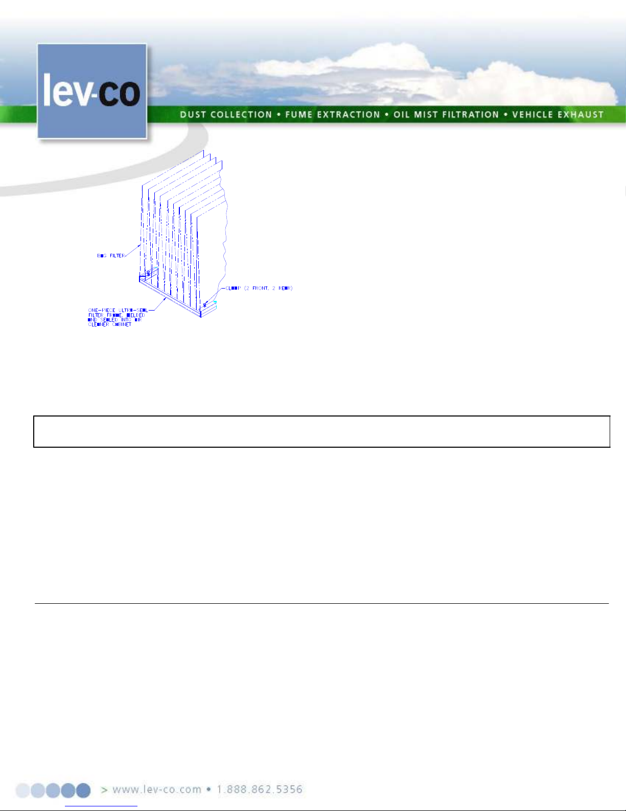
The 95% and 99% filters
self-
cleans by
gravity
-draining
Figure 6.
The Adsorption
Module
(AD)
option
is com
prised
of
(2) refillable,
finely
perforated
containers
to
hold
FILT
ER SERVICE
Filter service is required
when
a
reduction
of airf
low (sucti
on) is
notice
d, or on models
so
equi
p
ped,
reading on the gauge, (see diagram included with gauge for
ng is 1.0" the second mark
rns at or close to
to the sump pan. It will be necessary to occasionally
clean the filters if both grit and a mist are being collected.
Dry particulate can be removed from any of the pre-filter
assemblies by shaking or vacuum.
Tacky or embedded matter should be washed off in the
appropriate solvent.
Be sure when installing filters to observe the airflow direction as noted by an arrow on the side of the filter.
The unit will not be damaged if incorrectly installed, however performance will be degraded.
the
adsorption material in the air stream. As with the HEPA, it is located above the 95% filter.
The final filter configuration option available is the External Module. This external module can house either
a HEPA filter or an adsorption bank or a “DOUBLE BY-PASS” carbon fitler module. Filter access is from the top
cover of the module. The HEPA is secured with a clamping system
when
the optional pressure gauge indicates a restriction.
The optional pressure gauge is calibrated as follows:
With clean filters, turn unit on and mark the pressure
hook up). Make a second mark at 2.0" higher than initial reading (i.e. if initial readi
should be at 3.0").
Whether using a gauge or when airflow reduction is noticed, the following procedure should be followed.
1. Clean/replace pre-filter, turn unit back on, check performance. Normally, performance retu
original setting for the first several cleanings of the pre-filter.
2. If no performance improvement is evident after cleaning the pre-filter, replace or clean main filter.
Page: 9/15 .
Page 10

NOTE
FILTER
CLEAN
I
NG
1. Turn unit off and let
motor/blower co
m
e to a co
m
plete stop.
ent of the
return
FILTER
REPLACEMENT
1. Turn unit off and unp
l
ug from
electrical circuit.
HEPA
FILTER
: (on m
odels
so equipped)
cannot
be cleaned.
See your
distributor
for
replace
m
ent.
OTHER S
E
RVICE
Most other co
m
ponents of your MULTI
-
FLEX air cleaner requi
re little or no
routine servicing. Ite
ms
Unit can continue to run safely beyond the 2.0" pressure differential recommended, however
performance
will be reduced. Do not exceed 6.0" pressure differential across the filters.
2. Remove filter access panel.
3. Remove pre-filter.
4. Un-clip main filter in place
5. Slide out main filter.
6. Empty inlet and main dust trays to prevent dust from recollecting on filter.
7. To re-install, reverse the above steps.
8. Turn unit on and check suction and/or pressure gauge. If suction/pressure is still inadequate, replacem
main filter is required. If an optional third stage filter is used, ( i.e. HEPA or AD) and the above steps do not
the unit to specified performance, then replacement of the third stage filter will be necessary.
9. Oil smoke or vapor may cause decreased filter life.
2. Remove filter access panel.
3. Clean or replace pre-filter per above instructions.
4. Release filter retaining clamps located on filter holding frame (see Figure 6).
5. Slide filters out of the holding frame.
6. To replace, reverse the procedure above.
such as motors, blower wheels, friction joints of arms, pickup-hose and gaskets should be checked twice a year
under normal usage; more frequently under severe 24-hour-per-day usage. Clean, repair or replace parts as
Page: 10/15 .
Page 11
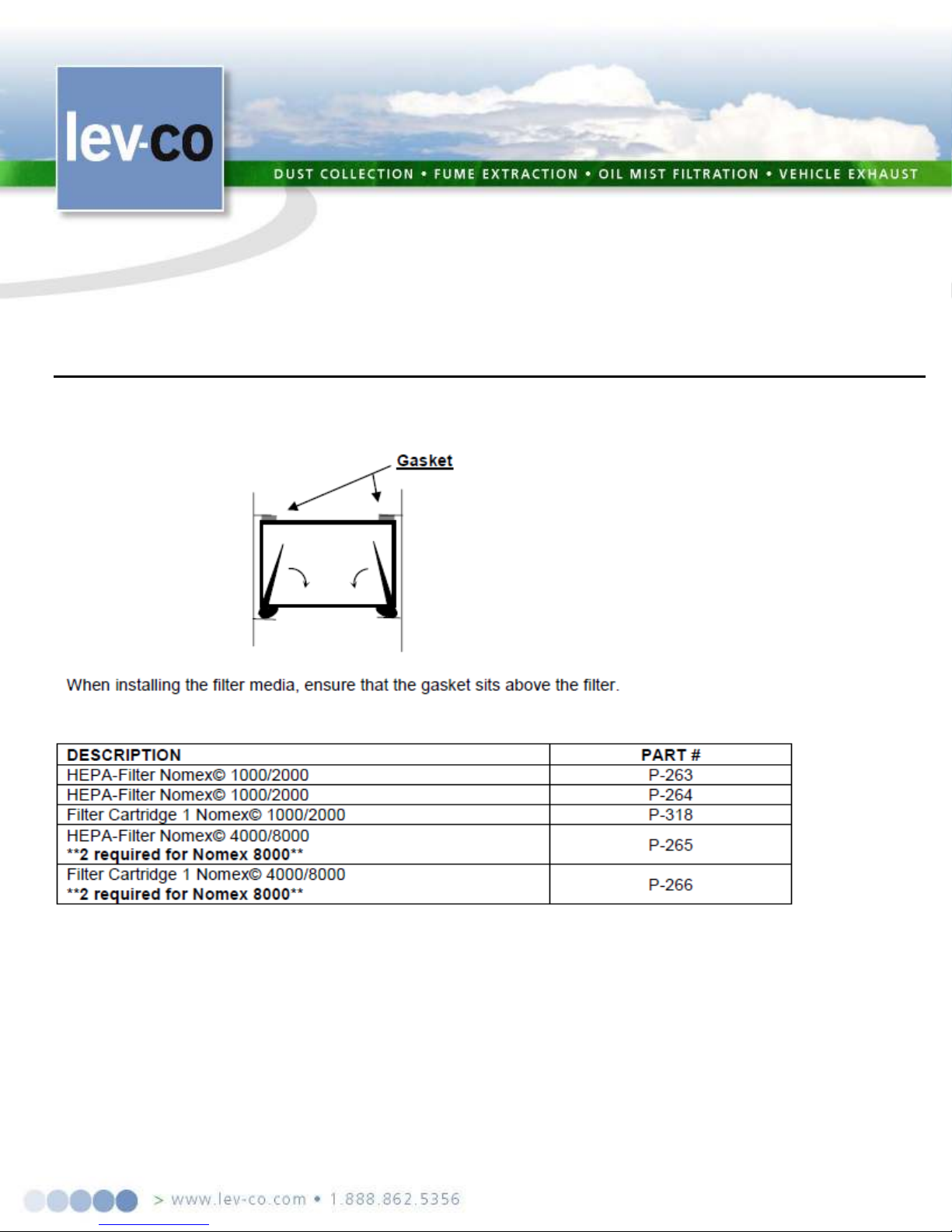
Check for dirt build
-
up on blower wheel and other r
o
tating parts, which can ca
u
se un
b
alance and resultant
vibration, noise, and short bearing life;
parts
and clean as necessary. An occasional drop of oil on the caster wheel bearing will keep them moving freely.
Replacement parts are available from your Lev-co distributor. The following section lists replacement
for the MULTI-FLEX unit.
REPLACEMENT PARTS
Page: 11/15 .
Page 12

TROUBLESHOOTING
The troubleshooting
guide
included
in
this m
anual
is
for qualified
personnel
only.
A
Motor
Trouble
Guide
is
included in Appendix A. If the unit does not function properly after following the guidelines in this manual, c
onsult
TROUBLESHOOTING
PROBL
E
M POSSIBLE
CAUSE
CORR
ECT
IVE ACT
I
ON
1. Light
(Optional)
1. La
m
p bu
r
ned out
1. Replace
Lamp
put
4. No input voltage
2. Motor won
'
t operate
1. Motor ove
r
load
1. Too
much airflow.
2. Failed
m
otor
3. Relay or
Starter failure
4. No input voltage
3. Low air flow
1. Duct disconnected
1. Inspect
an
d repair
4. Motor running slow
NOTES
a Lev-co representative for further help.
won't light
2. Control cable unplugged
3. Transformer burned out
2. Prefilter/filter plugged
3. Motor running backwards
2. Plug in connectors
3. Replace transformer.
With voltmeter check in
volts and 12 volt output
4. Check circuit breaker
Be sure arm, hose (or ducts),and
doors are installed before running.
2. Replace motor.
Check amps to ensure proper
operation.
3. Check overload reset.
Check magnet coil for failure
4. Check circuit breaker
2. Clean filter
3. Check rotation.
(3 phase only)
4. Check line voltage
Check motor current
Page: 12/15 .
Page 13

RECORD START UP
DAT
A H
E
RE
MODEL
:
MULTI
-
FLE
X
SERIAL
N
O.:
DATE
PUR
CHA
SED:
DATE IN
S
TALL
ED:
MOTOR
V
OLT
A
GE (MEASU
RE
D):
MOTOR
C
URR
E
NT (MEASU
RE
D):
MOTOR
FL
A (FROM
N
AMEPLA
TE):
MOTOR
VOLTAGE (FROM NAMEPLTE):
ALWAYS USE
LEV-CO REP
L
ACEM
ENT
PAR
T
S AND FI
LTERS TO MAINTAIN
W
ARRANTY
TO OR
DER SPARE
P
ARTS CONTACT
LEV-
CO
1050 BROCK ROAD, Unit 22
-24
Pickering, ON, CANADA L1W 3X4
Phone 905.831.7001 or 888.862.5356
E-MAIL:
sales@le
v-co.com
INTERNET: htt
p
://www.lev
-co.
com
FAX: 905.831.7443 or 866.840.9923
Page: 13/15 .
Page 14
(BRANCH CIRCUIT)
if
MOTOR WIRING GUIDE
WIRING
To connect motor for proper voltage and rotation, refer to connection diagram on nameplate or inside terminal/conduit box. If power factor
correction capacitors are used for individual motor power factor correction, do not exceed maximum recommended value.
All aspects of the installation must conform to the requirements of the NEC, including Article 430 (Motor Circuits and Controllers), and all
local codes. Wherever possible, each motor should be powered from a separate circuit of adequate capacity to keep voltage drop to a minimum during
starting and running. Increase wire size where motor is located a distance from the power source. Wire size must be adequate to minimize voltage drop
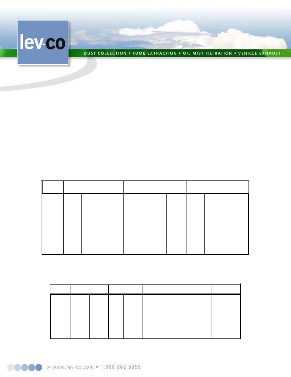
during starting and running. Refer to Tables A and B for suggested wire sizes. Distances shown are one-way between source and load. Portable cords,
used, should be as short as possible to minimize voltage drop. Long or inadequately sized cords, especially on hard starting loads, can cause motor
failure. Insulate and protect motor lead connections to prevent cut-through from sharp edges and vibration. Tape wire nuts to prevent loosening. All
electrical connections in system must be secure to prevent voltage drop and localized heating.
Determine direction of rotation before connecting driven equipment to prevent damage. Remove shaft key if motor is to be operated at noload. On three phase motors, interchange any two line leads (not motor leads) to reverse rotation. On air compressors, rotation of flywheel should direct
air towards the cylinders. Look for rotational arrow on flywheel.
All motors must be securely and adequately grounded by wiring with a grounded, metal-clad raceway system, using a separate ground bond
wire connected to bare metal on the motor frame, or other suitable means. Refer to NEC Article 250 (Grounding) for additional information.
Explosion-proof motors incorporating overtempature thermostats should be controlled with a magnetic starter. The thermostat circuit must be
wired in series with the holding coil circuit, as shown on tag or nameplate on motor, to remove power from the starter coil if motor overheats.
TABLE A - MINIMUM WIRE SIZES FOR THREE-PHASE MOTORS
MOTOR
HP
1/8
1/6
1/4
1/3
1/2
3/4
1
1½
2
3
[*]Type S, SO, SJ, SJO, etc. flexible cable wire sizes. See NEC Article 400 for ampacity
Note: Above wire sizes based on approximate 5% voltage drop during starting; copper conductors; and 75°C type TH, THW, RH, RHW, etc. insulation. For
wire, increase two wire size steps minimum. See NEC Article 310 for ampacities of aluminum conductors and 60°C type RUW, T, etc.
25 FT TO 50 FT
200V 230V 460V
14(18)*
14(18)*
14(18)*
14(18)*
14(18)*
14(18)*
14(18)*
14(18)*
14(16)*
14(18)*
14
14(16)*
14
14(16)*
12
12
10
200V 230V
14(18)*
14(18)*
14(18)*
14(18)*
14(18)*
14(18)*
14(18)*
14
14(18)*
12
14(18)*
12
14(18)*
14(18)*
14(18)*
14(16)*
14(16)*
14
12
10
10
8
8
100
FEET
460V
14(18)*
14(18)*
14(18)*
14(18)*
14(18)*
14(18)*
14(16)*
14(18)*
14
14(18)*
14
14(18)*
12
14(18)*
10
14(16)*
10
14(16)*
8
.
14
150 FT TO 200 FT
200V 230V 460V
14(16)*
14(18)*
14(16)*
14(16)*
14
12
10
8
8
6
6
4
14
14
12
10
10
8
6
6
14(18)*
14(18)*
14(18)*
14(18)*
14(18)*
14(16)*
14
14
12
12
insulation.
TABLE B - MINIMUM WIRE SIZES FOR SINGLE-PHASE MOTORS
MOT0R
HP
1/8
1/6
1/4
1/3
1/2
3/4
1
1½
2
3
[*] Type S, SO, SJ, SJO, etc. flexible cable wire sizes. See NEC Article 400 for ampacity.
Note:
Above wire sizes based on approximate 5% voltage drop during starting; copper conductors;and 75°C type TH, THW, RH, RHW, etc. insulation. For aluminum wire,
increase two wire size steps minimum. See NEC Article 310 for ampacities of aluminum conductors and 60°C type RUW, T, etc. insulation.
115V
14(16)*
14
14
14
14
12
10
10
8
8
25 FT
14(18)*
14(18)*
14(18)*
14(18)*
14(18)*
14(18)*
14(16)*
14(16)*
230V
14
10
50 FT
115V
14
12
12
10
10
230V
14(18)*
14(18)*
14(18)*
14(16)*
14(16)*
8
8
6
6
4
14
14
12
12
10
100 FT
115V
10
10
230V
14(16)*
14(16)*
8
8
8
6
4
4
3
2
14
14
14
12
10
10
8
8
150 FT
115V
10
8
6
6
6
4
4
2
2
1/0
230V
14(16)*
14
12
12
12
10
8
8
6
6
200 FT
115V
8
6
6
4
4
3
2
1
1/0
2/0
230V
14
12
12
10
10
8
8
6
6
4
aluminum
Page: 14/15 .
Page 15
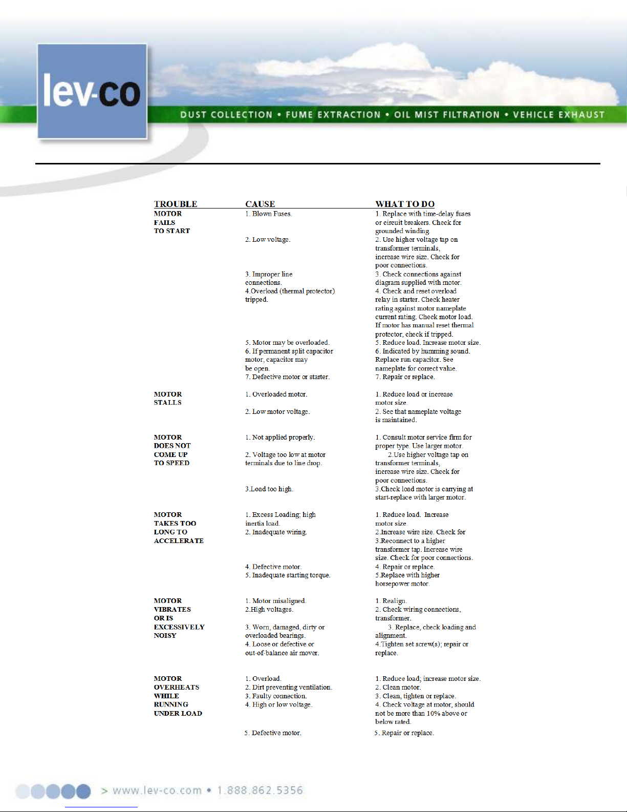
MOTOR TROUBLE GUID
E
The purpose of this guide is to suggest common answers to electrical problems. The information is not all-inclusive and does not necessarily apply in
all cases. When unusual operating conditions, repetitive failures, or other problems occur, consult an electric motor service firm for assistance.
Page: 15/15 .
 Loading...