

Page 1

TNT 35
Test monitoring units
607112 - 2010/11
Subject to change wit-
hout prior notice
CONNECTING AND OPERATING INSTRUCTIONS
Original Instructions
Page 2

Notes on Connecting and Operating Instructions
DEUTSCH ENGLISH FRANÇAIS ITALIANO ESPAÑOL NEDERLANDS
This conecting and operating instructions manual contains information on the proper use of
test monitoring units TNT
All the information contained herein, in particular the safety notes, need to be carefully
observed.
Notes regarding safety and warnings are marked by this symbol .
Notes regarding important pieces of information are marked by the symbol .
This connecting and operating instructions manual must be stored carefully. It must be
available for the entire operating time of the test monitoring units TNT
24V.
The Leuze electronic GmbH + Co. KG is not liable for damages caused by improper
use. Acquaintance with these instructions is an element of the knowledge required
for proper use.
© Reprints and reproduction, in whole or in part, are permitted only with the explicit
permission of
Leuze electronic GmbH + Co. KG
In der Braike 1
D-73277 Owen - Teck / Germany
Phone +49 (0) 7021 / 573-0
Fax +49 (0) 7021 / 573-199
info@leuze.de
www.leuze.com
35 and TNT 35/7-24V in accordance with its intended purpose.
35 and TNT 35/7-
2 TNT 35 und TNT 35/7-24V Leuze electronic
Page 3

Contents
1 General Information...........................................................................................................5
1.1 Certifications ........................................................................................................................5
1.2 General Information .............................................................................................................5
1.3 Definition of Terms...............................................................................................................5
1.4 Selection of Optical Electronic Protective Devices...............................................................6
2 Safety ..................................................................................................................................8
2.1 Approved purpose and foreseeable improper operation ......................................................8
2.1.1 Proper use............................................................................................................................8
2.1.2 Foreseeable misuse...........................................................................................................10
2.2 Competent personnel.........................................................................................................10
2.3 Responsibility for safety .....................................................................................................10
2.4 Exemption of liability ....................................................................................................................11
3 Mounting of the Safety System.......................................................................................12
3.1 Mounting of the Protective Photoelectric Sensor ...............................................................12
3.1.1 Multi-axle installation..........................................................................................................13
4 Function and Commissioning of the TNT 35.................................................................15
4.1 Function characteristics of the safety system ....................................................................15
4.1.1 Display and Operating Instruments....................................................................................15
4.2 Electrical Installation ..........................................................................................................16
4.2.1 Supply wiring......................................................................................................................17
4.2.2 Start input wiring ................................................................................................................18
4.2.3 Wiring of single-beam protective photoelectric sensors .....................................................20
4.2.4 Wiring of single-beam protective photoelectric sensors in series ......................................21
4.2.5 Wiring safety output ...........................................................................................................22
4.2.6 Wiring of the message outputs...........................................................................................25
4.2.7 Setting of the operating mode ............................................................................................26
4.3 Operating states without start- and restart-disable. .....................................................................28
4.4 Operating states with start- and restart-disable without relay monitoring (EDM).........................31
4.5 Operating states with start- and restart-disable and with relay monitoring (EDM).......................35
4.6 Fault indication and device reset........................................................................................38
4.7 Technical Data...................................................................................................................40
DEUTSCHENGLISHFRANÇAISITALIANOESPAÑOLNEDERLANDS
TNT 35/7-24V
Leuze electronic TNT 35 und TNT 35/7-24V 3
Page 4

Contents
5 Function and Commissioning of TNT 35/7-24V ............................................................ 42
5.1 Function characteristics of the safety system.................................................................... 42
DEUTSCH ENGLISH FRANÇAIS ITALIANO ESPAÑOL NEDERLANDS
5.1.1 Display and Operating Instruments.................................................................................... 43
5.2 Electrical Installation ..........................................................................................................43
5.2.1 Supply wiring...................................................................................................................... 44
5.2.2 Sensor voltage supply........................................................................................................44
5.2.3 Start input wiring ................................................................................................................ 45
5.2.4 Wiring of single-beam protective photoelectric sensors..................................................... 47
5.2.5 Wiring of single-beam protective photoelectric sensors in series ...................................... 48
5.2.6 Wiring safety output ........................................................................................................... 49
5.2.7 Wiring of the message outputs .......................................................................................... 51
5.2.8 Setting of the operating mode............................................................................................ 52
5.3 Operating states without start- and restart-disable. ........................................................... 54
5.4 Operating states with start- and restart-disable without relay monitoring (EDM).........................57
5.5 Operating states with start- and restart-disable and with relay monitoring (EDM).......................61
5.6 Fault indication and device reset ....................................................................................... 64
5.7 Technical Data ............................................................................................................................. 66
6 Applications .....................................................................................................................68
6.1 Example with retro-reflective photoelectric safety sensor SRK 96 .................................... 68
6.2 Example with a protective photoelectric sensor SLS 96 .............................................................70
6.3 Example with a protective light barrier ECO ................................................................................ 71
6.4 Example with a protective photoelectric barrier ROBUST...........................................................72
6.5 Example of a TNT 35 with protective photoelectric sensor SLS 96 and
6.6 Example of a TNT 35/7-24V with a retro-reflective photoelectric safety sensor SRK 96.............74
6.7 Example of a TNT 35/7-24V with two retro-reflective photoelectric safety sensors SRK 96 ....... 75
EMERGENCY SHUT-DOWN function......................................................................................... 73
7 Appendix........................................................................................................................... 76
7.1 Remaining Risks (EN ISO 12100-1) ..................................................................................76
8 EC Declaration of Conformity......................................................................................... 77
4 TNT 35 und TNT 35/7-24V Leuze electronic
Page 5

1 General Information
1.1 Certifications
The TNT 35 and TNT 35/7-24V monitoring units have been developed and manufactured
in accordance with the applicable European standards and directives.
The manufacturer of the product, Leuze electronic GmbH + Co. KG in D-73277 Owen -
, possesses a certified quality assurance system in accordance with ISO 9001.
Teck
TÜV NORD CERT GmbH
Zertifizierungsstelle für Produktsicherheit
Benannte Stelle 0044
Langemarckstr. 20
45141 Essen
1.2 General Information
Note!
There are two device variations described in this connecting and operating instructions.
The difference between the two devices is in their supply voltage. The TNT
DC operation. The TNT 35/7-24V is intended for 24V AC operation. The basic
for 24V
remarks concerning the functioning and assembly of the safety system are valid for both
device variations.
General Information
DEUTSCHENGLISHFRANÇAISITALIANOESPAÑOLNEDERLANDS
35 is intended
An active optoelectronic protective device is part of the electrical equipment which has to
be applied to those machines which contain the potential risk of bodily injury. They provide
protection by causing the machine to move into a safe operating state before a person can
get into a dangerous situation (EN 61496-1).
1.3 Definition of Terms
AOPD type 2
The EN 61496 describes two types of active optical electronic protective devices (AOPD)
with respect to the requirements concerning safety relevant parts of control units
ISO 13849-1).
(
The AOPD type 2 fulfills the requirements of category 2 acc. to ISO 13849-1. A periodic
function test has to detect malfunctions in the safety function. In case of a failure, the next
machine cycle may not be released. A malfunction of the AOPD type 2 between the
testings can cause the loss of the safety function. In normal function, at least one output
switching element of the AOPD type 2 has to move into the OFF-position if the sensor
reacts or if the power supply of the AOPD is interrupted.
Leuze electronic TNT 35 und TNT 35/7-24V 5
TNT 35/7-24V
Page 6

General Information
DEUTSCH ENGLISH FRANÇAIS ITALIANO ESPAÑOL NEDERLANDS
Contactless active protective device (BWS)
Corresponds to AOPD
Output switching element (OSSD)
The part of the AOPD which is connected to the machine control and which moves into the
OFF-position
Start disable
An equipment which disables the automatic machine start if the power supply of the
contactless active protective device is switched on or if it had been interrupted and
switched on again.
Start testing
A manual or automatic test which is performed after the contactless active protective
device has been switched on. It tests the complete safety-relevant control system before
the normal machine operation is induced.
Muting
The intentional bridging of the safety function, e.g. during material transport into the
hazardous area.
Muting sensors
Muting sensors define between persons and transported material. If the muting sensors are
activated simultaneously or in the intended order, the safety function of the AOPD is
bridged. Material can be brought into the hazardous area without taking the machine out of
operation.
Relay monitoring
The relay monitoring checks before every release of the switching outputs if the succeeding
contactors are open. Only then, a new release is possible.
as soon as the sensor part reacts during normal operation.
Restart-disable
A function which prevents an automatic restart of a machine after
• sensor detection during a potentially dangerous motion of the machine,
• a change in the operating mode of the machine and
• a change in the actuation mode of the machine.
1.4 Selection of Optical Electronic Protective Devices
The following strategy is to be applied (iterative process):
1. Determination of the protected area
2. Determination of the protective function
• Finger or hand protection
• Access protection for persons
• Presence detection
3. Determination of the control category
4. Calculation of the safety distance
6 TNT 35 und TNT 35/7-24V Leuze electronic
Page 7

General Information
Determination of the protected area
Through risk calculation, the following has to be observed:
• the size of the safety field
• the access points
• the hazardous areas
• bypassing possibilities
Determination of the protective function:
Finger and hand protection: The user is close to the hazardous area.
Access protection: Access to the hazardous area is protected.
Presence detection: A hazardous area which is completely surrounded by per-
manently installed protective devices is monitored for presence of objects or access protection and presence
detection are combined.
DEUTSCHENGLISHFRANÇAISITALIANOESPAÑOLNEDERLANDS
Leuze electronic TNT 35 und TNT 35/7-24V 7
TNT 35/7-24V
Page 8

Safety
2 Safety
DEUTSCH ENGLISH FRANÇAIS ITALIANO ESPAÑOL NEDERLANDS
Before using the Test Monitoring Unit, a risk evaluation must be performed according to
valid standards (e.g. EN
62061). The result of the risk assessment determines the required safety level of the
EN
Test Monitoring Unit (see
"TNT 35 Test Monitoring Units" as well as all applicable national and international
standards, regulations, rules and directives must be observed. Relevant and supplied
documents must be observed, printed out and handed to the affected personnel.
Before working with the Test Monitoring Unit, completely read and understand the
documents applicable to your task.
In particular, the following national and international legal regulations apply for the start-up,
technical inspections and work with Test Monitoring Units:
• Machinery directive 2006/42/EC
• Low voltage directive 2006/95/EC
• Electromagnetic compatibility directive 2004/108/EC
• Use of Work Equipment Directive 89/655/EEC supplemented by Directive 95/63 EC
• OSHA 1910 Subpart 0
• Safety regulations
• Accident-prevention regulations and safety rules
• Ordinance on Industrial Safety and Health and Labor Protection Act
• Device Safety Act
Notice!
For safety-related information you may also contact the local authorities (e.g., industrial
inspectorate, employer's liability insurance association, labor inspectorate, occupational
safety and health authority).
ISO 14121, EN ISO 12100-1, ISO 13849-1, IEC 61508,
Table 2.1-1). For mounting, operating and testing, document
2.1 Approved purpose and foreseeable improper operation
Warning!
A running machine can cause severe injuries!
Make certain that, during all conversions, maintenance work and inspections, the system is
securely shut down and protected against being restarted again.
2.1.1 Proper use
The Test Monitoring Unit must only be used after it has been selected in accordance with
the respectively applicable instructions and relevant standards, rules and regulations
regarding labor protection and occupational safety, and after it has been installed on the
machine, connected, commissioned, and checked by a competent person.
When selecting the Test Monitoring Unit it must be ensured that its safety-related capability
meets or exceeds the required performance level PL
8 TNT 35 und TNT 35/7-24V Leuze electronic
ascertained in the risk assessment.
r
Page 9

Safety
The following table shows the safety-related characteristic parameters of the TNT 35 and
35/7-24V series.
TNT
Type in accordance with IEC/EN 61496 Type 2
Performance Level (PL) in accordance with
ISO 13849-1: 2008
Category in accordance with ISO 13849-1 Cat. 2
Average probability of a failure to danger
per hour (PFH
Mean time to dangerous failure (MTTFd) 69 years
)
d
PL d
8.8 x 10⁻⁸ 1/h
DEUTSCHENGLISHFRANÇAISITALIANOESPAÑOLNEDERLANDS
Table 2.1-1: Safety-related characteristic parameters of the
• The Test Monitoring Unit is used in combination with one or more Multiple Light Beam
Safety Devices or Safety Light Curtains to safeguard danger zones or points of
operation.
• The control of the machine or system that is to be safeguarded must be electrically
influenceable. A switch command initiated by a TNT 35 or TNT 35/7-24V must result in
an immediate shutdown of the dangerous movement.
• The "Reset" acknowledgment button for unlocking the start/restart interlock must be
mounted outside the danger zone and in such a way that the entire danger zone can be
seen from its mounting location.
• Message outputs (state outputs) must not be used for switching safety-relevant signals.
• The Test Monitoring Unit is designed for installation in a cabinet or a protective housing
with a protection rating of at least IP
• The 24 V DC ±20% power supply must guarantee safe isolation from the mains voltage
and be able to bridge a power outage period of 20
• Depending on external wiring, dangerous voltages may be present at the switching
outputs. In addition to the power supply, these must be switched off and safeguarded
against being switched back on prior to all work on the TNT
• These operating instructions must be included with the documentation of the machine on
which the protective device is installed so that they are available to the operator at all
times.
• Manipulating the Test Monitoring Unit also voids all warranty claims against the
manufacturer of the Test Monitoring Unit.
• The Test Monitoring Unit must be tested regularly by competent personnel.
• The safety distance between the AOPD and the point of operation is to be maintained. It
is calculated according to the formulas for machine-specific C standards or given in the
general B1 standard ISO
braking time of the machine must be taken into account.
• Two switching contacts must always be looped into the switch-off circuit of the machine.
To prevent welding, relay switching contacts must be fused/protected externally accord
ing to the technical data.
• The Test Monitoring Unit must be exchanged after a maximum of 20 years. Repairs or
the exchange of parts subject to wear and tear do not extend the service life.
TNT 35 and TNT 35/7-24V series
54.
ms.
35.
13855. The reaction time of the Test Monitoring Unit and the
-
TNT 35/7-24V
Leuze electronic TNT 35 und TNT 35/7-24V 9
Page 10

Safety
2.1.2 Foreseeable misuse
DEUTSCH ENGLISH FRANÇAIS ITALIANO ESPAÑOL NEDERLANDS
Any use other than that defined under the "intended use" or which goes beyond that use is
considered improper use!
e.g.
• applications in explosive or easily flammable atmospheres
• use on machines with long periods of downtime
Attention!
Such instances can jeopardize the health and lives of the personnel operating the
machinery and/or may cause damage to property.
2.2 Competent personnel
Prerequisites for competent personnel:
• he has a suitable technical education
• he knows the rules and regulations for occupational safety, safety at work and safety
technology and can assess the safety of the machine
• he knows the instructions for the Test Monitoring Unit and the machine
• he has been instructed by the responsible person on the mounting and operation of the
machine and of the Test Monitoring Unit
2.3 Responsibility for safety
Manufacturer and operating company must ensure that the machine and implemented Test
Monitoring Unit function properly and that all affected persons are adequately informed and
trained.
The type and content of all imparted information must not lead to unsafe actions by users.
The manufacturer of the machine is responsible for:
• safe machine construction
• safe implementation of the Test Monitoring Unit
• imparting all relevant information to the operating company
• adhering to all regulations and directives for the safe starting-up of the machine
The company operating the machine is responsible for:
• instructing the operating personnel
• maintaining the safe operation of the machine
• adhering to all regulations and directives for occupational safety and safety at work
• regular testing by competent personnel
10 TNT 35 und TNT 35/7-24V Leuze electronic
Page 11

2.4 Exemption of liability
Leuze electronic GmbH + Co. KG is not liable in the following cases:
• Test Monitoring Unit is not used as intended
• safety notices are not adhered to
• reasonably foreseeable misuse is not taken into account
• mounting and electrical connection are not properly performed
• proper function is not tested
• changes are made to the Test Monitoring Unit
Safety
DEUTSCHENGLISHFRANÇAISITALIANOESPAÑOLNEDERLANDS
Leuze electronic TNT 35 und TNT 35/7-24V 11
TNT 35/7-24V
Page 12

Mounting of the Safety System
3 Mounting of the Safety System
DEUTSCH ENGLISH FRANÇAIS ITALIANO ESPAÑOL NEDERLANDS
Note!
The mounting instructions in this chapter have to be heeded for fault-free functioning of the
whole safety system.
3.1 Mounting of the Protective Photoelectric Sensor
It is absolutely mandatory that the valid guidelines and standards are observed when
mounting the protective photoelectric sensors.
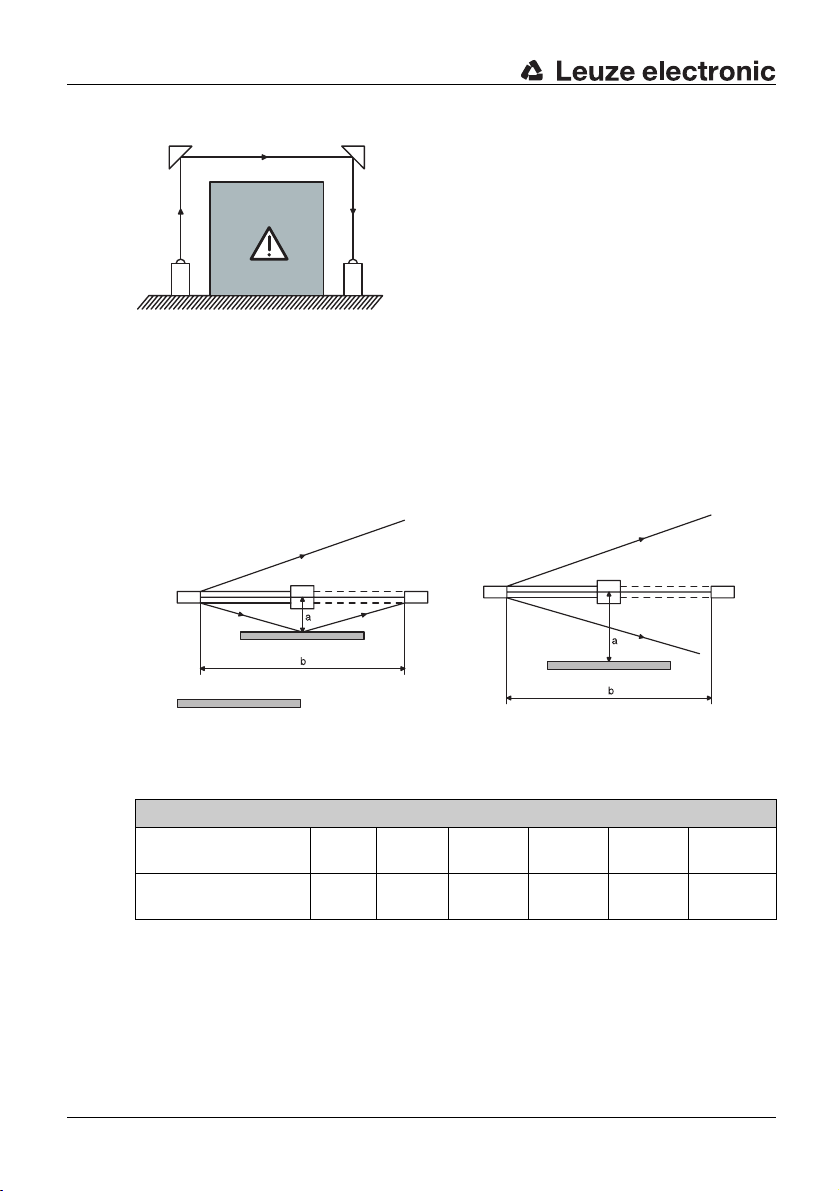
Safety distance
A certain time delay applies between the interruption of the light beam of the protective
photoelectric sensors and the stand-still of the machine. The photoelectric sensors have to
be installed in such a way that the dangerous area cannot be reached within this time
delay. The minimum distance for safeguarding the hazardous area is 850
mm.
Figure 3.1-1:Safety distance S between photoelectric sensor and hazardous area
Calculation of the safety distance
The safety distance S between photoelectric sensor and hazardous area is calculated acc.
to IS0 13855 using the following formula:
S = K * T+C
S = Safety distance between photoelectric sensor and hazardous area
K = Grip and approach speed
T = Time delay between interruption of the light beam and stand-still of the machine
C = Safety constant
1200 mm for single-axle arrangement,
850 mm for multi-axle arrangement
Example for the calculation of the safety distance:
A machine with a system response time of 100 ms has to be equipped with a two-beam
safeguarding. The response time of the two-beam AOPD and the test monitoring unit
35 is 20 ms.
TNT
12 TNT 35 und TNT 35/7-24V Leuze electronic
Page 13

Application of the formula: S = K * T+C
Where:
S = the minimum distance of the two-beam AOPD from the hazardous area
K = approach speed 1600 mm/s (IS0 13855)
T = sum of the system response time of the machine and response time of the AOPD
850 mm with multi-axle installation
This results in:
S = (1600 mm/s * (100 ms + 20 ms)) + 850 mm
S = 1042 mm
3.1.1 Multi-axle installation
For the safeguarding of hazardous areas, the level of desired protection and the number of
light beams are determined in IS0 13855 or through a risk analysis acc. to
With multi-axle installation, parallel light beams always have to run in opposite directions.
Otherwise the light beams can cause mutual interference and disturb proper functioning.
Depending on the number of photoelectric sensor pairs, the single systems have to be
mounted at different heights acc. to IS0 13855. The number of needed systems results
from the corresponding type C standard or risk evaluation.
Mounting of the Safety System
DEUTSCHENGLISHFRANÇAISITALIANOESPAÑOLNEDERLANDS
ISO 13849-1.
T
R
T
Figure 3.1-2:Multi-axle installation
Deflection mirrors
A number of important factors have to be observed when using deflection mirrors:
• With any light beam deflection, a loss of operating range occurs. Per deflection mirror,
the loss is approx. 15
• Contamination of the deflection mirrors should be avoided.
• Environmental conditions such as steams and dust-containing air heavily limit the
operating range.
• When installing deflection mirrors, the optical axis of the photoelectric sensor must be
centered to the mirror.
• A laser alignment aid made by Leuze, e.g. ARH 2 facilitates alignment over large
distances.
Leuze electronic TNT 35 und TNT 35/7-24V 13
%.
R
T
R
TNT 35/7-24V
Page 14
Mounting of the Safety System
DEUTSCH ENGLISH FRANÇAIS ITALIANO ESPAÑOL NEDERLANDS
Figure 3.1-3:Arrangement of the deflection mirrors
Reflection bypass
Surfaces located parallel to the light beam can cause a reflection bypass. An object within
the light path is then no longer detected.
The photoelectric sensor has to be mounted with a minimum lateral distance to the
reflecting surface. This distance results from the opening angle (±4°) and the distance
between transmitter and receiver.
reflecting surface
Wrong arrangement
Figure 3.1-4:Reflection bypass
Minimum distance to the reflecting surface
Between transmitter
and receiver
To light beam (a)
approx.
14 TNT 35 und TNT 35/7-24V Leuze electronic
(b)
2 m 3 m 4 m 5 m 6 m 10 m
0.20 m 0.30 m 0.40 m 0.50 m 0.60 m 1.0 m
Correct arrangement
Page 15

Function and Commissioning of the TNT 35
4 Function and Commissioning of the TNT 35
4.1 Function characteristics of the safety system
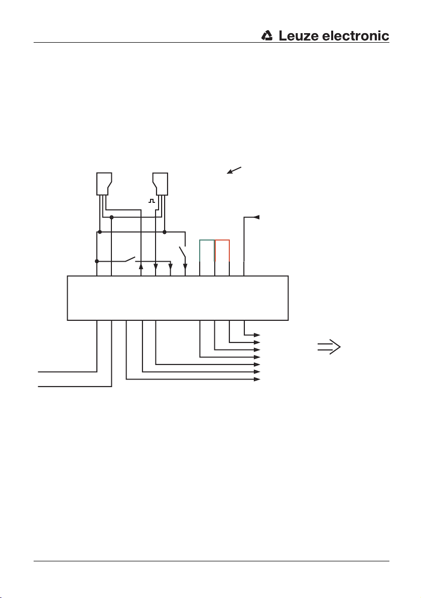
The complete safety system consists of a TNT 35 and accompanying protective photoelectric sensors or light barriers.
The operating mode is selected using a jumper
between:
terminal 22 & 23 (with start-/restart-disable)
Transmitter
Start/
Active
Active
Receiver
Operation with start-/
and restart-disable
Operation without start-/
and restart-disable
Reset
15
2414
or
terminal 23 & 24 (without start-/restart-disable)
The device is shipped from the factory with the
jumper set between terminal 22 and 23
(with start-/restart-disable function)
EDM (relay monitoring, feedback circuit)
13232216 21
TNT 35
GND
5
6
302978
3231
Safety output 2
}
Safety output 1
}
Message output "Safety
On"
Emergency
shut-down
DEUTSCHENGLISHFRANÇAISITALIANOESPAÑOLNEDERLANDS
+24V
Figure 4.1-1:Installation of the complete safety system
After the TNT 35 is switched on via the start input, the functionality of the protective
photoelectric sensors is monitored in two-second cycles.
The electrical integration into the controller has to be performed acc. to the corresponding
safety category acc. to
ISO 13849-1. The voltage free safety relay outputs can be directly
used for shut-down of the dangerous movement.
Inside the monitoring unit TNT 35, a selectable start- and restart-disable, as well as a
selectable relay monitoring input are integrated.
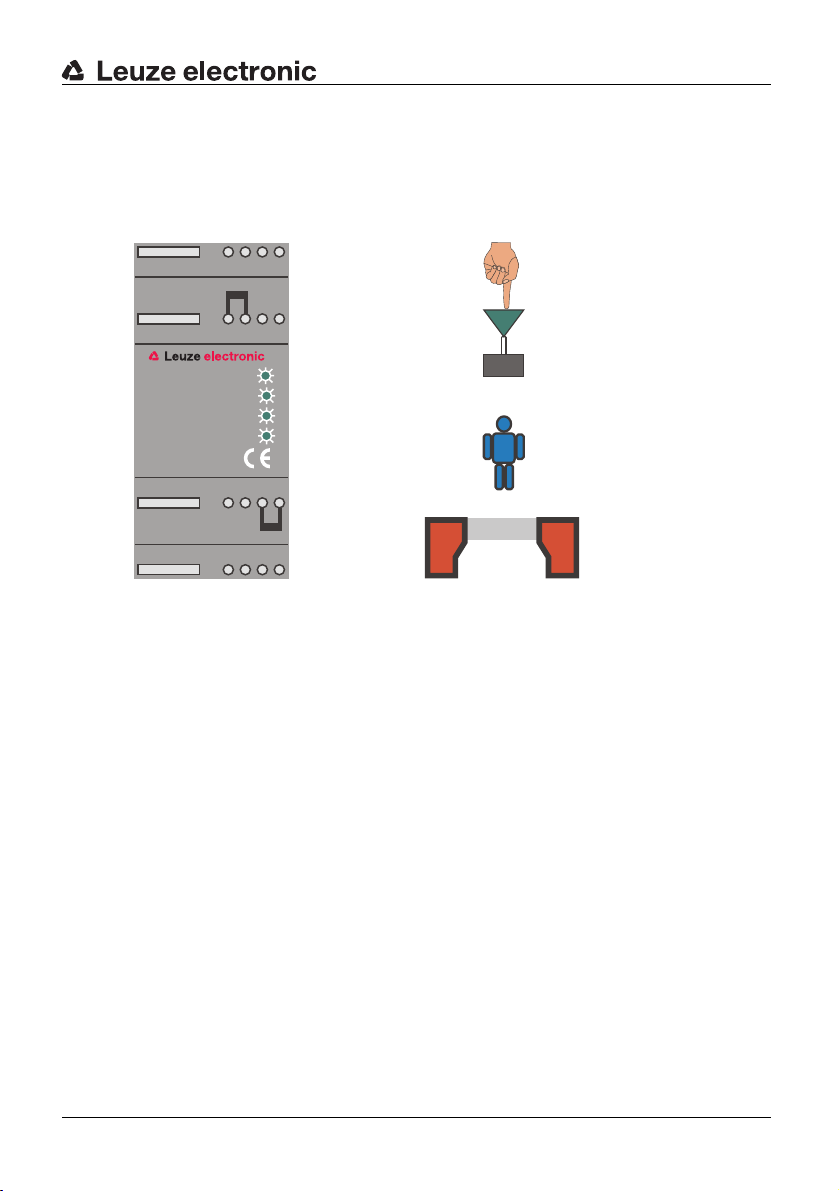
4.1.1 Display and Operating Instruments
The test monitoring unit TNT 35 features integrated LEDs to indicate the state of the
system.
The start- and restart-disable, as well as the relay monitoring functions are set on the
35 using the corresponding jumpers on the connection terminals.
TNT
Leuze electronic TNT 35 und TNT 35/7-24V 15
TNT 35/7-24V
Page 16

Function and Commissioning of the TNT 35
Overview - Display Elements
DEUTSCH ENGLISH FRANÇAIS ITALIANO ESPAÑOL NEDERLANDS
• LED "Sensor"
Status of the safety field state
• LED "Start/Active"
Status of the start and activation input
•LED "EDM"
Status of the relay monitoring
• LED "OFF/ON"
Status of the safety circuit (open or closed)
5 6 87
13 14 15 16
Sensor
Start/Active
EDM
OFF/ON
TNT35
21 22 23 24
29 30 31 32
Figure 4.1-2:Display elements TNT 35
4.2 Electrical Installation
Warning!
The electrical installation is only to be performed by specialised personnel.
Supply and signal lines have to be installed separately from power lines during installation.
Inside the switching cabinet, suitable spark extinction has to be provided if using
contactors.
When installing drive motors and brakes, the corresponding installation manuals have to be
observed.
The power supply for the TNT 35 must be equipped with a protective mains separation
device according to IEC 60742. The power supply unit used to operate the TNT
be able to compensate for changes and interruptions of the supply voltage acc. to
61496-1.
EN
16 TNT 35 und TNT 35/7-24V Leuze electronic
35 has to
Page 17

4.2.1 Supply wiring
The test monitoring unit TNT 35 is supplied with 24V DC +/- 15%. The max. current
consumption is 200mA.
The +24V supply voltage is connected to terminal 5 and the GND is connected to
6.
terminal
+24V GND
5 6 87
13 14 15 16
Sensor
Start/Active
EDM
OFF/ON
TNT35
21 22 23 24
29 30 31 32
Function and Commissioning of the TNT 35
DEUTSCHENGLISHFRANÇAISITALIANOESPAÑOLNEDERLANDS
Figure 4.2-1:Supply wiring
Leuze electronic TNT 35 und TNT 35/7-24V 17
TNT 35/7-24V
Page 18

Function and Commissioning of the TNT 35
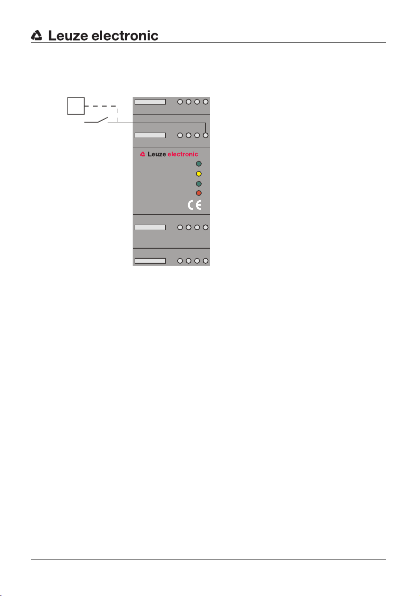
4.2.2 Start input wiring
DEUTSCH ENGLISH FRANÇAIS ITALIANO ESPAÑOL NEDERLANDS
The Start input (terminal 16) works both in the operating mode "with start- and restartdisable" and "without start- and restart-disable" in different ways:
• In the operating mode with start- and restart-disable, the TNT 35 expects two signal
changes (push-button function) as switch-on signal. A failure in the
start-/restart button, e.g. due to contact malfunction is safely detected by the TNT 35.
PLC
+24V
5 6 87
13 14 15 16
Sensor
Start/Active
EDM
OFF/ON
TNT35
21 22 23 24
29 30 31 32
Figure 4.2-2:Wiring of the start input "with start- and restart-disable"
18 TNT 35 und TNT 35/7-24V Leuze electronic
Page 19
Function and Commissioning of the TNT 35
• In the operating mode without start- and restart-disable, the start input works as
activation input. As soon as a HIGH active signal is present at the start input (terminal
16) and the safety field is free, the safety outputs are closed.
PLC
+24V
5 6 87
13 14 15 16
Sensor
Start/Active
EDM
OFF/ON
TNT35
21 22 23 24
29 30 31 32
Figure 4.2-3:Wiring of the start input "without start- and restart-disable"
DEUTSCHENGLISHFRANÇAISITALIANOESPAÑOLNEDERLANDS
Leuze electronic TNT 35 und TNT 35/7-24V 19
TNT 35/7-24V
Page 20

Function and Commissioning of the TNT 35
4.2.3 Wiring of single-beam protective photoelectric sensors
DEUTSCH ENGLISH FRANÇAIS ITALIANO ESPAÑOL NEDERLANDS
The activation input of the protective photoelectric sensor can be directly connected to
terminal 14 on the TNT
35. The switching output of the receiver can be directly connected
to terminal 15.
The GND potential present on terminal 6 serves as a reference potential for both signals.
The supply of the protective photoelectric sensors comes directly from the 24V power
supply unit.
+24V
GND
T
Active
R
+24V
GND
5 6 87
13 14 15 16
Sensor
Start/Active
EDM
OFF/ON
TNT35
21 22 23 24
29 30 31 32
Figure 4.2-4:Wiring of single-beam protective photoelectric sensors
20 TNT 35 und TNT 35/7-24V Leuze electronic
Page 21

Function and Commissioning of the TNT 35
4.2.4 Wiring of single-beam protective photoelectric sensors in series
Several photoelectric sensor pairs can be connected in series with multi-axle arrangements
on a machine or system. The adjacent picture shows a three-axle photoelectric sensor
arrangement. It is possible to operate up to six photoelectric sensor pairs on one TNT
35.
+24V
GND
+24V
GND
T
R
Active
Active
R
+24V
GND
5 6 87
13 14 15 16
T
+24V
GND
Sensor
Start/Active
EDM
OFF/ON
TNT35
Active
R
+24V
GND
21 22 23 24
29 30 31 32
+24V
GND
T
Figure 4.2-5:Wiring of single-beam protective photoelectric sensors in series
Function characteristics:
The TNT 35 (terminal 14) activates the first photoelectric sensor transmitter. The receiver is
activated via the first optical path and, by using its output, activates the second
photoelectric sensor transmitter. The supply has to provided on each photoelectric
transmitter and receiver. The feedback to the TNT
35 (terminal 15) is done by the last
photoelectric sensor receiver within the series connection.
Any time the light axis is interrupted, a message is issued to the TNT 35 through the series
connection.
The series connection tests every transmitter and receiver for function capability while
performing the testing procedure.
DEUTSCHENGLISHFRANÇAISITALIANOESPAÑOLNEDERLANDS
TNT 35/7-24V
Leuze electronic TNT 35 und TNT 35/7-24V 21
Page 22

Function and Commissioning of the TNT 35
4.2.5 Wiring safety output
DEUTSCH ENGLISH FRANÇAIS ITALIANO ESPAÑOL NEDERLANDS
Integration in a one-channel release circuit without relay monitoring
Two safety relay outputs are connected in series. The release circuit can be connected to
further components which are then wired to a common EMERGENCY SHUT-DOWN
device.
5 6 87
13 14 15 16
Sensor
Start/Active
EDM
OFF/ON
TNT35
21 22 23 24
29 30 31 32
Release circuit
Figure 4.2-6:Wiring safety output (one-channel release circuit)
Note!
For the operating mode without relay monitoring, the jumper that short-circuits terminals 13
and 14 must be set.
22 TNT 35 und TNT 35/7-24V Leuze electronic
Page 23

Function and Commissioning of the TNT 35
Integration in a two-channel release circuit without relay monitoring
Both safety relay outputs are integrated seperately into the release circuits. These circuits
can be connected with additional components which trigger a common EMERGENCY
SHUT-DOWN device.
5 6 87
13 14 15 16
Sensor
Start/Active
EDM
OFF/ON
TNT35
21 22 23 24
29 30 31 32
Release circuit 1
Release circuit 2
Figure 4.2-7:Wiring safety output (two-channel release circuit)
Note!
For the operating mode without relay monitoring, the jumper that short-circuits terminals 13
and 14 must be set.
DEUTSCHENGLISHFRANÇAISITALIANOESPAÑOLNEDERLANDS
TNT 35/7-24V
Leuze electronic TNT 35 und TNT 35/7-24V 23
Page 24
Function and Commissioning of the TNT 35
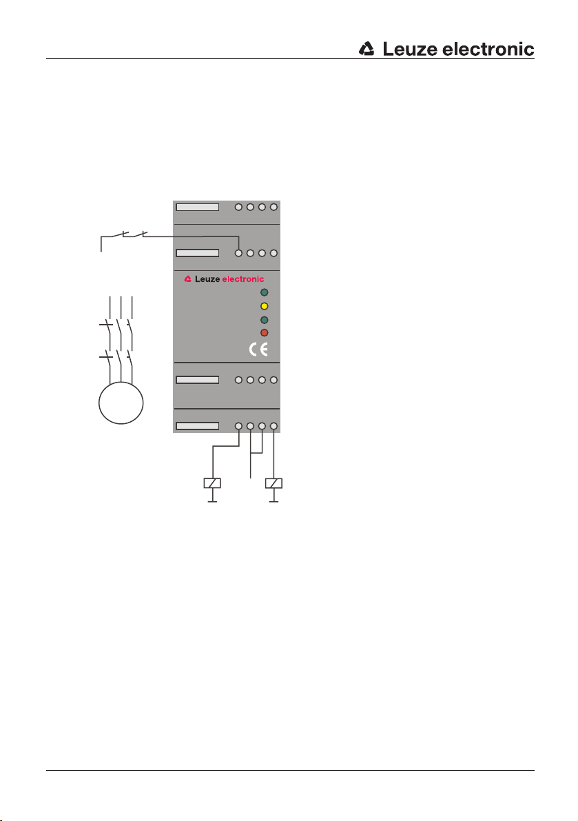
Integration with relay monitoring as EMERGENCY SHUT-DOWN device
DEUTSCH ENGLISH FRANÇAIS ITALIANO ESPAÑOL NEDERLANDS
The motor contactors for dangerous movement are connected to both safety relay outputs.
For this purpose, forced contactors have to be used. In the connection diagram, no fuses
are included. However, for correct function fuses are absolutely required. The maximum
contact load of the safety relay outputs is 4A with 24VDC.
Control of the motor contactors happens via K1 and K2. If a contact of K1 and K2 should
weld, a message is issued to the TNT
the unit is possible only after removal of the failure in the output circuit.
35 through the feedback circuit (EDM). A new start of
5 6 87
13 14 15 16
Sensor
Start/Active
EDM
OFF/ON
21 22 23 24
29 30 31 32
+24V
K2
+24V
K1 K2
M
K1
K2
TNT35
K1
Figure 4.2-8:Wiring of the safety output with relay monitoring
24 TNT 35 und TNT 35/7-24V Leuze electronic
Page 25

Function and Commissioning of the TNT 35
4.2.6 Wiring of the message outputs
Two message outputs are integrated in the TNT 35. Both are HIGH active, positive
switching semiconductor outputs and can be either directly connected to a PLC or control a
status display of a machine.
The message output "Safety on" is always active if the safety relay outputs are closed.
The message output "Error" is always active if the TNT 35 detects an error. Those errors
can be internal or external.
Through linking of the status outputs in the controller, the following system states can be
detected:
1. "Safety on" active, "Error" inactive
Normal operation of the TNT 35, no error detected
2. "Safety on" inactive, "Error" active
The TNT 35 detected a safety relevant failure which led to the switching off of the safety
outputs.
Message output "Error"
Message output "Safety On"
5 6 87
13 14 15 16
Sensor
Start/Active
EDM
OFF/ON
TNT35
21 22 23 24
DEUTSCHENGLISHFRANÇAISITALIANOESPAÑOLNEDERLANDS
29 30 31 32
Figure 4.2-9:Wiring of the message outputs
Leuze electronic TNT 35 und TNT 35/7-24V 25
TNT 35/7-24V
Page 26

Function and Commissioning of the TNT 35
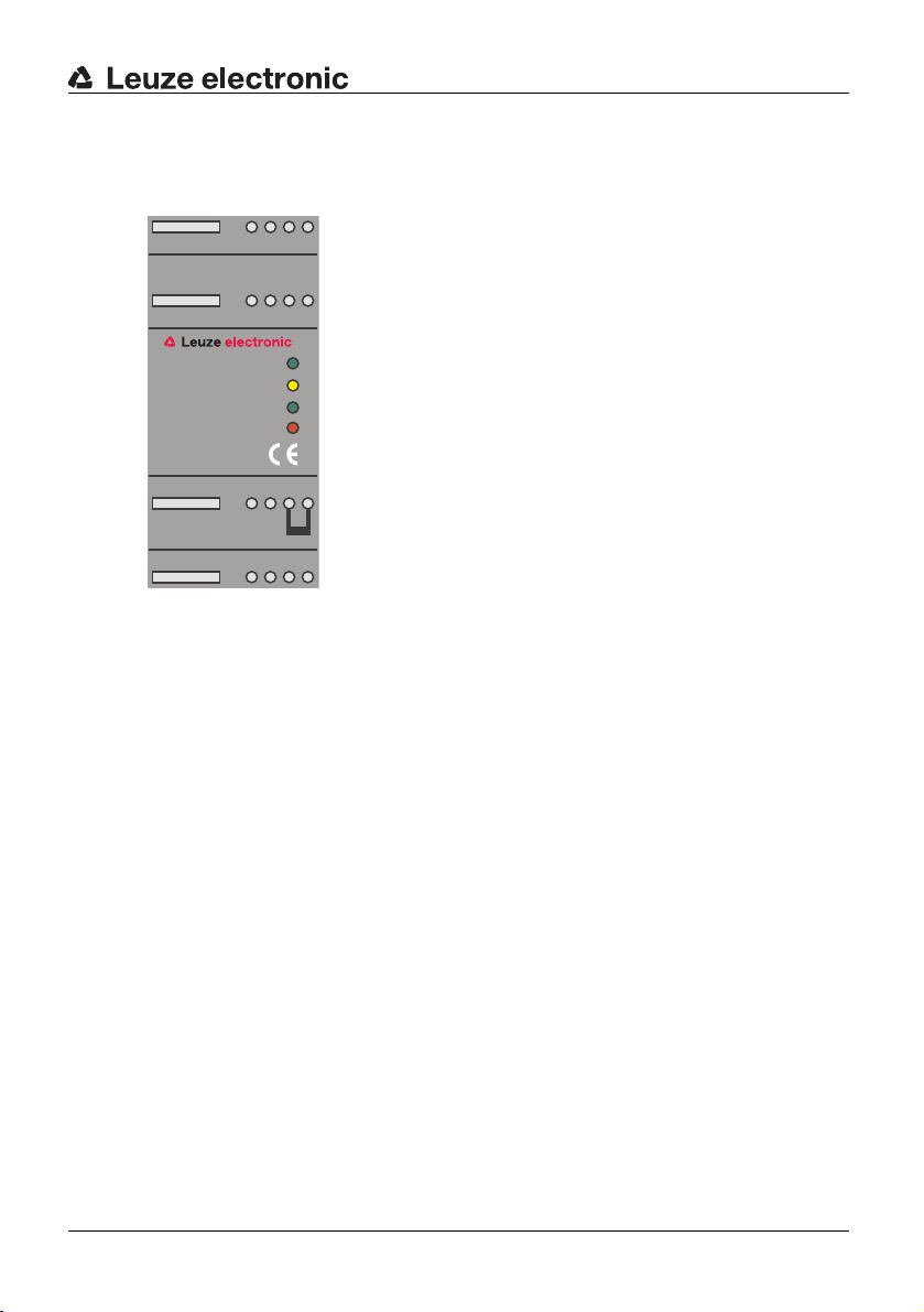
4.2.7 Setting of the operating mode
DEUTSCH ENGLISH FRANÇAIS ITALIANO ESPAÑOL NEDERLANDS
The start- and restart-disable function is selected on the device by setting a jumper
between terminals 22 and 23 or terminals 23 and 24.
Warning!
Terminals 22, 23 and 24 may only be used to for selecting the operating mode using the
included short circuit jumpers.
With start- and restart-disable:
The device is shipped with a jumper between terminals 22 and 23, i.e. the start- and
restart-disable is active.
5 6 87
13 14 15 16
Sensor
Start/Active
EDM
OFF/ON
TNT35
21 22 23 24
29 30 31 32
Figure 4.2-10:Operating mode "with start- and restart-disable"
26 TNT 35 und TNT 35/7-24V Leuze electronic
Page 27
Function and Commissioning of the TNT 35
Without start- and restart-disable:
The start- restart-disable is set to inactive by connecting a jumper between terminals 23
and 24.
5 6 87
13 14 15 16
Sensor
Start/Active
EDM
OFF/ON
TNT35
21 22 23 24
29 30 31 32
Figure 4.2-11:Operating mode "without start- and restart-disable"
Completing the setting:
After the setting has been changed, the new device setting must be saved. This is done
either by triggering the Reset input (terminal 21) or by switching the suppy voltage on and
off for a short time.
DEUTSCHENGLISHFRANÇAISITALIANOESPAÑOLNEDERLANDS
Leuze electronic TNT 35 und TNT 35/7-24V 27
TNT 35/7-24V
Page 28

Function and Commissioning of the TNT 35
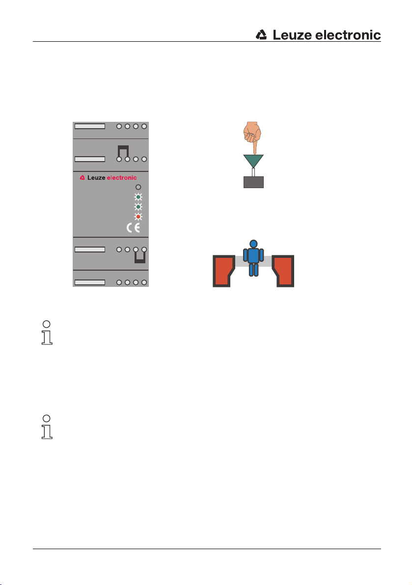
4.3 Operating states without start- and restart-disable.
DEUTSCH ENGLISH FRANÇAIS ITALIANO ESPAÑOL NEDERLANDS
Stand-by operation:
The free light path is displayed by the green LED "Sensor".
Activation is not used.
The safety outputs are open. This state is displayed by the red LED.
The display for the relay monitoring (EDM) is active.
5 6 87
13 14 15 16
Sensor
Start/Active
EDM
OFF/ON
Start
Activation
TNT35
21 22 23 24
SLS
29 30 31 32
Figure 4.3-1:Display of the TNT 35 in stand-by operation
28 TNT 35 und TNT 35/7-24V Leuze electronic
Page 29
Function and Commissioning of the TNT 35
Safety operation:
In safety operation, the function of the protective photoelectric sensor is cyclically tested
every two seconds. The free safety field is displayed by the green LED.
Activation is used (green LED). The safety output is closed which is displayed by the green
LED.
5 6 87
DEUTSCHENGLISHFRANÇAISITALIANOESPAÑOLNEDERLANDS
13 14 15 16
Sensor
Start/Active
EDM
OFF/ON
Start
Activation
TNT35
21 22 23 24
SLS
29 30 31 32
Figure 4.3-2:Display of the TNT 35 in safety operation
TNT 35/7-24V
Leuze electronic TNT 35 und TNT 35/7-24V 29
Page 30
Function and Commissioning of the TNT 35
Safety field interruption:
DEUTSCH ENGLISH FRANÇAIS ITALIANO ESPAÑOL NEDERLANDS
If during safety operation the protective photoelectric sensor is interrupted or the +24V
activation signal on the active input is switched off, then the safety output is opened.
After the safety field has been cleared again and the startup test has been completed
successfully, the TNT
Sensor
Start/Active
OFF/ON
35 automatically switches the safety relay output back on again.
5 6 87
13 14 15 16
EDM
TNT35
21 22 23 24
29 30 31 32
Figure 4.3-3:Display of the TNT 35 during a safety field interruption
Start
Activation
SLS
Note!
The input for the relay monitoring (terminal 13) always must be wired. For operation without
the relay monitoring function, a jumper can be set between terminal 13 and terminal 14.
Connected relays can be monitored if the wiring of the input to terminal 13 is carried out
according to the connection diagram "Operation with relay monitoring as EMERGENCY
SHUT-DOWN device".
Faulty wiring results in the the safety outputs not switching on. If a fault occurs, the safety
outputs switch off with a maximum delay of two seconds.
Note!
The activation input must be wired with +24V in order for the safety inputs to switch on!
30 TNT 35 und TNT 35/7-24V Leuze electronic
Page 31

Function and Commissioning of the TNT 35
4.4 Operating states with start- and restart-disable without relay monitoring (EDM)
Stand-by operation:
The free light path is displayed by the green LED "Sensor".
The start input has not been activated.
The safety output is open. This state is displayed by the red LED "OFF/ON". The yellow
LED "Start" displays the lock of the start- and restart-disable.
5 6 87
13 14 15 16
Sensor
Start/Active
EDM
OFF/ON
TNT35
21 22 23 24
29 30 31 32
Start
Activation
SLS
DEUTSCHENGLISHFRANÇAISITALIANOESPAÑOLNEDERLANDS
Figure 4.4-1:Display of the TNT 35 in stand-by operation
Leuze electronic TNT 35 und TNT 35/7-24V 31
TNT 35/7-24V
Page 32

Function and Commissioning of the TNT 35
Test operation:
DEUTSCH ENGLISH FRANÇAIS ITALIANO ESPAÑOL NEDERLANDS
In test operation, the proper functioning of both the protective photoelectric sensor and the
test monitoring unit is checked.
To induce the test operation, the start input is activated (green LED "Start").
As long as the start-/restart button is pressed, the test operation remains active.
After release of the start-/restart button, the TNT 35 changes from test operation to safety
operation.
5 6 87
13 14 15 16
Sensor
Start/Active
EDM
OFF/ON
TNT35
21 22 23 24
29 30 31 32
Start
Activation
SLS
Figure 4.4-2:Display of the TNT 35 in test operation
32 TNT 35 und TNT 35/7-24V Leuze electronic
Page 33

Function and Commissioning of the TNT 35
Safety operation:
In safety operation, the function of the protective photoelectric sensor is cyclically tested
every two seconds. The free safety field is displayed by the green LED "Sensor".
The safety outputs are closed which is displayed by the green LED "OFF/ON".
5 6 87
13 14 15 16
Sensor
Start/Active
EDM
OFF/ON
Start
Activation
TNT35
21 22 23 24
SLS
29 30 31 32
Figure 4.4-3:Display of the TNT 35 in safety operation
DEUTSCHENGLISHFRANÇAISITALIANOESPAÑOLNEDERLANDS
TNT 35/7-24V
Leuze electronic TNT 35 und TNT 35/7-24V 33
Page 34

Function and Commissioning of the TNT 35
Safety field interruption:
DEUTSCH ENGLISH FRANÇAIS ITALIANO ESPAÑOL NEDERLANDS
The safety outputs of the TNT 35 are opened (LED "OFF/ON" on red) if during safety
operation the light beam of the protective photoelectric sensor is interrupted.
The restart-disable inside the TNT 35 becomes active and prevents an automatic restart of
the machine. The yellow LED "Start" displays the function of the restart-disable.
The TNT 35 is in waiting state and can be restarted by pressing the start-/restart button
after the safety field is free.
5 6 87
13 14 15 16
Sensor
Start/Active
EDM
OFF/ON
TNT35
21 22 23 24
29 30 31 32
Figure 4.4-4:Display of the TNT 35 during a safety field interruption
Start
Activation
SLS
34 TNT 35 und TNT 35/7-24V Leuze electronic
Page 35

Function and Commissioning of the TNT 35
4.5 Operating states with start- and restart-disable and with relay monitoring (EDM)
Stand-by operation:
The free light path is displayed by the green LED "Sensor".
The relay monitoring (EDM) is active (green LED "EDM").
The safety output is open. This state is displayed by the red LED "OFF/ON". The yellow
LED "Start" displays the lock of the start- and restart-disable.
5 6 87
13 14 15 16
DEUTSCHENGLISHFRANÇAISITALIANOESPAÑOLNEDERLANDS
Sensor
Start/Active
EDM
OFF/ON
Start
Activation
TNT35
21 22 23 24
SLS
29 30 31 32
Figure 4.5-1:Display of the TNT 35 in stand-by operation
TNT 35/7-24V
Leuze electronic TNT 35 und TNT 35/7-24V 35
Page 36

Function and Commissioning of the TNT 35
Test operation:
DEUTSCH ENGLISH FRANÇAIS ITALIANO ESPAÑOL NEDERLANDS
In test operation, the proper functioning of both the protective photoelectric sensor and the
test monitoring unit is checked.
To induce the test operation, the start input is activated (green LED "Start").
As long as the start-/restart button is pressed, the test operation remains active.
After release of the start-/restart button, the TNT 35 changes from test operation to safety
operation.
5 6 87
13 14 15 16
Sensor
Start/Active
EDM
OFF/ON
TNT35
21 22 23 24
29 30 31 32
Start
Activation
SLS
Figure 4.5-2:Display of the TNT 35 in test operation
36 TNT 35 und TNT 35/7-24V Leuze electronic
Page 37

Function and Commissioning of the TNT 35
Safety operation:
In safety operation, the function of the protective photoelectric sensor is cyclically tested
every two seconds. The free safety field is displayed by the green LED "Sensor".
The relay monitoring is inactive in safety operation (green LED "EDM" off).
The safety outputs are closed which is displayed by the green LED "OFF/ON".
5 6 87
13 14 15 16
DEUTSCHENGLISHFRANÇAISITALIANOESPAÑOLNEDERLANDS
Sensor
Start/Active
EDM
OFF/ON
Start
Activation
TNT35
21 22 23 24
SLS
29 30 31 32
Figure 4.5-3:Display of the TNT 35 in safety operation
TNT 35/7-24V
Leuze electronic TNT 35 und TNT 35/7-24V 37
Page 38

Function and Commissioning of the TNT 35
Safety field interruption:
DEUTSCH ENGLISH FRANÇAIS ITALIANO ESPAÑOL NEDERLANDS
The safety outputs of the TNT 35 are opened (LED "OFF/ON" on red) if during safety
operation the light beam of the protective photoelectric sensor is interrupted.
The restart-disable inside the TNT 35 becomes active and prevents an automatic restart of
the machine. The yellow LED "Start" displays the function of the restart-disable.
The TNT 35 is in waiting state and can be restarted by pressing the start-/restart button
after the safety field is free.
5 6 87
13 14 15 16
Sensor
Start/Active
EDM
OFF/ON
Start
Activation
TNT35
21 22 23 24
SLS
29 30 31 32
Figure 4.5-4:Display of the TNT 35 during a safety field interruption
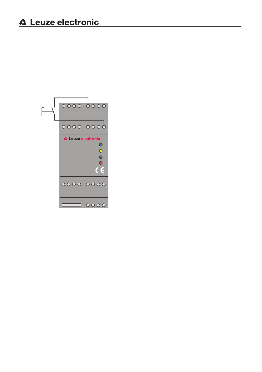
4.6 Fault indication and device reset
Faults of the test monitoring unit TNT 35 are indicated by the blinking of the red "ON/OFF"
LED. The possible faults are:
Fault in the operating mode selection:
The selected operating mode of the device at startup (with/without start- and restartdisable) changed during operation. The jumper (terminal 22 to terminal 23 or terminal 23 to
terminal 24) should be checked that it is set to the desired operating mode.
Fault in the relay monitoring:
A fault in the wiring or soldered safety contacts was detected by the TNT 35. The wiring
and connected contacts should be checked.
Internal device failures:
Equipment faults that are caused by an internal defect result in the unit going into locked
state.
38 TNT 35 und TNT 35/7-24V Leuze electronic
Page 39

Function and Commissioning of the TNT 35
Resetting from a locked state:
Resetting from a locked state is carried out by disconnecting the supply voltage for a short
time or by applying a reset signal (+24V potential) to the reset input (terminal 21).
The LED will stop blinking after the fault has been eliminated and the device reset from the
locked state.
5 6 87
13 14 15 16
Sensor
Start/Active
EDM
OFF/ON
TNT35
21 22 23 24
+24V
29 30 31 32
Figure 4.6-1:Resetting from a locked state
DEUTSCHENGLISHFRANÇAISITALIANOESPAÑOLNEDERLANDS
TNT 35/7-24V
Leuze electronic TNT 35 und TNT 35/7-24V 39
Page 40

Function and Commissioning of the TNT 35
4.7 Technical Data
DEUTSCH ENGLISH FRANÇAIS ITALIANO ESPAÑOL NEDERLANDS
Safety-relevant technical data
Type in accordance with
IEC/EN 61496
Performance Level (PL) in accor-
dance with ISO 13849-1: 2008
Category in accordance with
13849-1
ISO
Average probability of a failure
to danger per hour (PFH
)
d
Mean time to dangerous failure
)
(MTTF
d
Degree of cover DC 94%
Number of cycles until 10 % of
the components have a
failure to danger (B
10d
)
Service life (TM) 20 years
Electrical data
Supply voltage Ub 24V DC +/-15 %
Residual ripple < 15 %
Current consumption approx. 200 mA
Response time < 20 ms
Delay before start-up approx. 2 s
Type 2
PL d
Cat. 2
8.8 x 10⁻⁸ 1/h
69 years
DC 13 - 24 V: 10 million switching cycles (2 A)
AC 15 - 230 V: 100,000 switching cycles (2 A)
600,000 switching cycles (1 A)
1.3 million switching cycles (0.5 A)
Sensors
Transmitter activation PNP (HIGH active)
Receiver input optical coupler input,
input current approx. 10 mA
40 TNT 35 und TNT 35/7-24V Leuze electronic
Page 41

Function and Commissioning of the TNT 35
In- and outputs
Start input optical coupler input (High active)
input current approx. 10 mA
Reset input optical coupler input (High active)
input current approx. 10 mA
Relay monitoring (EDM) optical coupler input (High active)
input current approx. 10 mA
Message output Safety on PNP transistor output, 100 mA
short circuit- and polarity reversal protection
Message output Error PNP transistor output, 100 mA
short circuit- and polarity reversal protection
Safety output voltage free make-contact
max. switching voltage 250V AC
max. current load 4 A
Safeguarding externally with max. 4 A slow blow
Overvoltage category 2 for rating voltage 300V AC
according to VDE 0110 part 1
Environmental data
Ambient temperature -20°C - +60°C
Storage temperature -30°C - +70°C
Protection class IP 40 (only for application in electrical operating
rooms/switching cabinet with minimum protection
class IP 54 is suitable)
DEUTSCHENGLISHFRANÇAISITALIANOESPAÑOLNEDERLANDS
Impact resistance/Vibration resistance
EMB/EMV acc. to EN 61496-1
Contact protection acc. to VBG 4 and VDE 0106 part 100
Mechanical data
Housing Polyamide PA 6.6/grey
Connection Screw terminals,
connection cross-section 0.2 - 2.5 mm
Mounting snap-on mounting for standard rail
according to EN 50022
Weight approx. 200 g
Dimensions (WxHxD) 45 mm x 100 mm x 115 mm
Leuze electronic TNT 35 und TNT 35/7-24V 41
TNT 35/7-24V
Page 42
Function and Commissioning of TNT 35/7-24V
5 Function and Commissioning of TNT 35/7-24V
DEUTSCH ENGLISH FRANÇAIS ITALIANO ESPAÑOL NEDERLANDS
5.1 Function characteristics of the safety system
The TNT 35/7-24V has been designed for mounting on a standard rail in a suitable
switching cabinet. The complete safety system consists of a TNT
nying protective photoelectric sensors or light barriers.
The operating mode is selected using a jumper between:
terminal 22 & 23 (with start-/restart-disable)
or
Transmitter
Receiver
Active
terminal 23 & 24 (without start-/restart-disable)
The device is shipped from the factory with the jumper
set between terminal 23 and 24
(without start-/restart-disable function)
35/7-24V and accompa-
Reset
Start/
Active
15
10 2
20
14 4 12
513232216 21
TNT 35/7-24V
19 17 18
91
24V AC
Figure 5.1-1:Installation of the complete safety system
After the TNT 35/7-24V is switched on via the start input, the functionality of the protective
photoelectric sensors is monitored in two-second cycles.
The electrical integration into the control has to be performed acc. to the corresponding
safety category acc. to
ISO 13849-1. The voltage free safety relay outputs can be directly
used for shut-down of the dangerous movement.
Inside the Test Monitoring unit TNT 35/7-24V, a selectable start- and restart-disable, as
well as a selectable
relay monitoring input are integrated.
786
EDM (relay monitoring, feedback circuit)
Operation with start-/
and restart-disable
Operation without start-/
and restart-disable
24
3029
311
3231
Safety output 2
}
Safety output 1
}
Message output "Safety off"
Message output "Safety on"
Emergency
shut-down
42 TNT 35 und TNT 35/7-24V Leuze electronic
Page 43

Function and Commissioning of TNT 35/7-24V
5.1.1 Display and Operating Instruments
The test monitoring unit TNT 35/7-24V features integrated LEDs to indicate the state of the
system.
The start- and restart-disable, as well as the relay monitoring functions are set on the
35/7-24 using the corresponding jumpers on the connection terminals.
TNT
Overview - Display Elements
• LED "Sensor"
Status of the safety field state
• LED "Start/Active"
Status of the start and activation input
•LED "EDM"
Status of the relay monitoring
• LED "OFF/ON"
Status of the safety circuit (open or closed)
DEUTSCHENGLISHFRANÇAISITALIANOESPAÑOLNEDERLANDS
243
1
9101112
5 6 87
13 14 15 16
Sensor
Start/Active
EDM
OFF/ON
TNT35/7-24V
17 18 19 20
21 22 23 24
29 30 31 32
Figure 5.1-2:Display elements TNT 35/7-24V
5.2 Electrical Installation
Warning!
The electrical installation is only to be performed by specialised personnel.
Supply and signal lines have to be installed separately from power lines during installation.
Inside the switching cabinet, suitable spark extinction has to be provided if using
contactors. In connection with driving motors and breaks, the corresponding manuals have
to be observed.
The power supply for the TNT 35/7-24V must be equipped with a protective mains
separation device according to IEC
35/7-24V has to be able to compensate for changes and interruptions of the supply
TNT
voltage acc. to EN
61496-1.
TNT 35/7-24V
60742. The power supply unit used to operate the
Leuze electronic TNT 35 und TNT 35/7-24V 43
Page 44

Function and Commissioning of TNT 35/7-24V
5.2.1 Supply wiring
DEUTSCH ENGLISH FRANÇAIS ITALIANO ESPAÑOL NEDERLANDS
5.2.2 Sensor voltage supply
The test monitoring unit TNT 35/7-24V is supplied with 24VAC -10/+15%. Current consumption is max. 200mA (without safety sensors). The supply voltage 24V AC is connected
to terminals 1 and 9.
The built-in power suppy of the TNT 35/7-24V also supplies the connected safety sensors.
A supply voltage of +24VDC is available at terminals 5, 10 and 11. The corresponding GND
potential is available on terminals 2, 3 and 6. The maximum current consumption of the
safety sensors may not exceed 200
24VAC
GND for the
supply of the
sensors
+24V GND
mA.
1 243
10 11 12
9
5 6 87
13 14 15 16
Sensor
Start/Active
EDM
OFF/ON
+24V for the
supply of the
sensors
TNT35/7-24V
17 18 19 20
21 22 23 24
29 30 31 32
Figure 5.2-1:Supply wiring
Warning!
The supply voltage may only be used for the connected safety sensors and the
corresponding start and reset signals. Connecting additional components can damage the
device!
44 TNT 35 und TNT 35/7-24V Leuze electronic
Page 45
5.2.3 Start input wiring
The Start input (terminal 16) works both in the operating mode "with start- and restartdisable" and "without start- and restart-disable" in different ways:
• In the operating mode with start- and restart-disable, the TNT 35/7-24V expects two
signal changes (push-button function) as switch-on signal. A failure in the start-/restart
+24V
button, e.g. due to contact malfunction is safely detected by the TNT
Start
A 24V suppy terminal (e.g. terminals 5, 10 or 11) can be used for the start signal.
+24V
Start
1 243
Function and Commissioning of TNT 35/7-24V
35/7-24V.
5 6 87
DEUTSCHENGLISHFRANÇAISITALIANOESPAÑOLNEDERLANDS
10 11 12
9
13 14 15 16
Sensor
Start/Active
EDM
OFF/ON
TNT35/7-24V
17 18 19 20
21 22 23 24
29 30 31 32
Figure 5.2-2:Wiring of the start input "with start- and restart-disable"
TNT 35/7-24V
Leuze electronic TNT 35 und TNT 35/7-24V 45
Page 46

Function and Commissioning of TNT 35/7-24V
• In the operating mode without start- and restart-disable, the start input works as
DEUTSCH ENGLISH FRANÇAIS ITALIANO ESPAÑOL NEDERLANDS
activation input. As soon as a HIGH active signal is present at the start input (terminal
16) and the safety field is free, the safety outputs are closed.
A 24V suppy terminal (e.g. terminals 5, 10 or 11) can be used for the activation signal.
+24V
Start
1 243
5 6 87
10 11 12
9
13 14 15 16
Sensor
Start/Active
EDM
OFF/ON
TNT35/7-24V
17 18 19 20
21 22 23 24
29 30 31 32
Figure 5.2-3:Wiring of the start input "without start- and restart-disable"
46 TNT 35 und TNT 35/7-24V Leuze electronic
Page 47

Function and Commissioning of TNT 35/7-24V
5.2.4 Wiring of single-beam protective photoelectric sensors
The activation input of the protective photoelectric sensor can be directly connected to
14 on the TNT 35/7-24V.
terminal
The switching output of the receiver can be directly connected to terminal 15.
The +24V supply for the safety sensors is taken from the supply terminals 5, 10 and 11, the
GND reference potential is taken from terminals 2, 3 and 6.
DEUTSCHENGLISHFRANÇAISITALIANOESPAÑOLNEDERLANDS
T
GND
+24V
Active
R
GND
+24V
1 243
10 11 12
9
5 6 87
13 14 15 16
Sensor
Start/Active
EDM
OFF/ON
TNT35/7-24V
17 18 19 20
21 22 23 24
29 30 31 32
Figure 5.2-4:Wiring of single-beam protective photoelectric sensors
TNT 35/7-24V
Leuze electronic TNT 35 und TNT 35/7-24V 47
Page 48

Function and Commissioning of TNT 35/7-24V
5.2.5 Wiring of single-beam protective photoelectric sensors in series
DEUTSCH ENGLISH FRANÇAIS ITALIANO ESPAÑOL NEDERLANDS
Several photoelectric sensor pairs can be connected to the TNT 35/7-24 in series with
multi-axle arrangements on a machine or system. The adjacent picture shows a three-axle
photoelectric sensor arrangement. It is possible to operate up to three photoelectric sensor
T
Active
35/7-24V.
R
+24V
GND
1 243
5 6 87
pairs on one TNT
+24V
GND
+24V
GND
+24V
GND
R
T
Active
Active
10 11 12
9
T
+24V
GND
+24V
GND
TNT35/7-24V
17 18 19 20
R
13 14 15 16
Sensor
Start/Active
EDM
OFF/ON
21 22 23 24
29 30 31 32
Figure 5.2-5:Wiring of single-beam protective photoelectric sensors in series
Function characteristics:
The TNT 35/7-24V (terminal 14) activates the first photoelectric sensor transmitter. The
receiver is activated via the first optical path and, by using its output, activates the second
photoelectric sensor transmitter. The supply has to provided on each photoelectric
transmitter and receiver. The feedback to the TNT
35/7-24V (terminal 15) is done by the
last photoelectric sensor receiver within the series connection.
Any time the light axis is interrupted, a message is issued to the TNT 35/7-24V through the
series connection.
The series connection tests every transmitter and receiver for function capability while
performing the testing procedure.
48 TNT 35 und TNT 35/7-24V Leuze electronic
Page 49

5.2.6 Wiring safety output
Integration in a one-channel release circuit without relay monitoring
Two safety relay outputs are connected in series. The release circuit can be connected to
further components which are then wired to a common EMERGENCY SHUT-DOWN
device.
1 243
5 6 87
Function and Commissioning of TNT 35/7-24V
DEUTSCHENGLISHFRANÇAISITALIANOESPAÑOLNEDERLANDS
10 11 12
9
13 14 15 16
Sensor
Start/Active
EDM
OFF/ON
TNT35/7-24V
17 18 19 20
Release circuit
21 22 23 24
29 30 31 32
Figure 5.2-6:Wiring safety output (one-channel release circuit)
TNT 35/7-24V
Leuze electronic TNT 35 und TNT 35/7-24V 49
Page 50

Function and Commissioning of TNT 35/7-24V
Integration in a two-channel release circuit without relay monitoring
DEUTSCH ENGLISH FRANÇAIS ITALIANO ESPAÑOL NEDERLANDS
Both safety relay outputs are integrated seperately into the release circuits. These circuits
can be connected with additional components which trigger a common EMERGENCY
SHUT-DOWN device.
1 243
10 11 12
9
5 6 87
13 14 15 16
Sensor
Start/Active
EDM
OFF/ON
TNT35/7-24V
17 18 19 20
Release circuit 1
Release circuit 2
21 22 23 24
29 30 31 32
Figure 5.2-7:Wiring safety output (two-channel release circuit)
50 TNT 35 und TNT 35/7-24V Leuze electronic
Page 51

Function and Commissioning of TNT 35/7-24V
Integration with relay monitoring as EMERGENCY SHUT-DOWN device
The motor contactors for dangerous movement are connected to both safety relay outputs.
For this purpose, forced contactors have to be used. In the connection diagram, no fuses
are included. However, for correct function fuses are absolutely required. The maximum
contact load of the safety relay outputs is 4A with 24VDC.
The suply of the relay monitoring (EDM) is made from the supply terminals 5, 10 or 11.
Control of the motor contactors happens via K1 and K2. If a contact of K1 and K2 should
fuse together, a message is issued to the TNT
(EDM). A new start of the unit is possible only after removal of the failure in the output
circuit.
35/7-24V through the feedback circuit
DEUTSCHENGLISHFRANÇAISITALIANOESPAÑOLNEDERLANDS
K1 K2
+24V from terminal
5, 10 or 11
K1
K2
1 243
10 11 12
9
Sensor
Start/Active
OFF/ON
TNT35/7-24V
17 18 19 20
M
K1 K2
Figure 5.2-8:Wiring of the safety output with relay monitoring
5.2.7 Wiring of the message outputs
Two message outputs are integrated in the TNT 35/7-24V. Both are high-active, positive
switching semiconductor outputs and can be connected to potential free inputs of an SPS.
This requires connection to the GND potential of terminal 2, 3 or 6 as reference.
5 6 87
13 14 15 16
EDM
21 22 23 24
29 30 31 32
+24V
TNT 35/7-24V
Warning!
The reference potential on terminals 2, 3 and 6 may not be connected with the GND
potential of the machine
or the controller.
A faulty connection can damage the device!
Leuze electronic TNT 35 und TNT 35/7-24V 51
Page 52

Function and Commissioning of TNT 35/7-24V
The Message output "Safety" is a potential free relay output. The relay actuation input is at
DEUTSCH ENGLISH FRANÇAIS ITALIANO ESPAÑOL NEDERLANDS
terminal 17. The make-contact (terminal 19) is always active when the safety outputs are
closed. The break-contact (terminal 18) is active if the safety outputs are open.
The message output "Error" is always active if the TNT 35/7-24V detects an error. Those
errors can be internal or external.
Message output "Error"
Message output "Safety On"
1 243
10 11 12
9
5 6 87
13 14 15 16
Sensor
Start/Active
EDM
OFF/ON
TNT35/7-24V
Message out-
put "Safety"
Switch-over
Break-contact
Make-contact
17 18 19 20
21 22 23 24
29 30 31 32
Figure 5.2-9:Wiring of the message outputs
Warning!
The message outputs on terminals 17, 18 and 19 are only approved for 24V DC operation.
Do not connect to higher voltages!
5.2.8 Setting of the operating mode
The start- and restart-disable function is selected on the device by setting a jumper
between terminals 22 and 23 or terminals 23 and 24.
Warning!
Terminals 22, 23 and 24 may only be used to for selecting the operating mode using the
included short circuit jumpers.
52 TNT 35 und TNT 35/7-24V Leuze electronic
Page 53

Function and Commissioning of TNT 35/7-24V
With start- and restart-disable:
The device is shipped with a jumper between terminals 22 and 23, i.e. the start- and
restart-disable is active.
1 243
10 11 12
9
5 6 87
13 14 15 16
Sensor
Start/Active
EDM
OFF/ON
TNT35/7-24V
17 18 19 20
21 22 23 24
29 30 31 32
Figure 5.2-10:Operating mode "with start- and restart-disable"
Without start- and restart-disable:
The start- and restart-disable is set to inactive by connecting a jumper between terminals
23 and 24.
1 243
10 11 12
9
5 6 87
13 14 15 16
Sensor
Start/Active
EDM
OFF/ON
TNT35/7-24V
17 18 19 20
21 22 23 24
DEUTSCHENGLISHFRANÇAISITALIANOESPAÑOLNEDERLANDS
TNT 35/7-24V
29 30 31 32
Figure 5.2-11:Operating mode "with start- and restart-disable"
Leuze electronic TNT 35 und TNT 35/7-24V 53
Page 54

Function and Commissioning of TNT 35/7-24V
Completing the setting:
DEUTSCH ENGLISH FRANÇAIS ITALIANO ESPAÑOL NEDERLANDS
After the setting has been changed, the new device setting must be saved. This is done
either by triggering the Reset input (terminal 21) or by switching the suppy voltage on and
off for a short time.
5.3 Operating states without start- and restart-disable.
Stand-by operation:
The free light path is displayed by the green LED "Sensor".
Activation is not used. The safety outputs are open. This state is displayed by the red LED.
The display for the relay monitoring (EDM) is active.
1 243
10 11 12
9
5 6 87
13 14 15 16
Sensor
Start/Active
EDM
OFF/ON
Start
Activation
TNT35/7-24V
17 18 19 20
21 22 23 24
SLS
29 30 31 32
Figure 5.3-1:Display of the TNT 35/7-24V in stand-by operation
54 TNT 35 und TNT 35/7-24V Leuze electronic
Page 55

Function and Commissioning of TNT 35/7-24V
Safety operation:
In safety operation, the function of the protective photoelectric sensor is cyclically tested
every two seconds. The free safety field is displayed by the green LED.
Activation is used (green LED). The safety output is closed which is displayed by the green
LED.
1 243
10 11 12
9
5 6 87
13 14 15 16
Start
Sensor
Start/Active
EDM
OFF/ON
Activation
TNT35/7-24V
17 18 19 20
21 22 23 24
SLS
29 30 31 32
Figure 5.3-2:Display of the TNT 35/7-24V in safety operation
DEUTSCHENGLISHFRANÇAISITALIANOESPAÑOLNEDERLANDS
TNT 35/7-24V
Leuze electronic TNT 35 und TNT 35/7-24V 55
Page 56

Function and Commissioning of TNT 35/7-24V
Safety field interruption:
DEUTSCH ENGLISH FRANÇAIS ITALIANO ESPAÑOL NEDERLANDS
If during safety operation the protective photoelectric sensor is interrupted or the +24V
activation signal on the active input is switched off, then the safety output is opened.
After the safety field has been cleared again and the startup test has been completed
successfully, the TNT
35/7-24V automatically switches the safety relay output back on
again.
1 243
10 11 12
9
5 6 87
13 14 15 16
Start
Sensor
Start/Active
EDM
OFF/ON
Activation
TNT35/7-24V
17 18 19 20
21 22 23 24
SLS
29 30 31 32
Figure 5.3-3:Display of the TNT 35/7-24V during a safety field interruption
Note!
The input for the relay monitoring (terminal 13) always must be wired. For operation without
the relay monitoring function, a jumper can be set between terminal 13 and terminal 14.
Connected relays can be monitored if the wiring of the input to terminal 13 is carried out
according to the connection diagram "Operation with relay monitoring as EMERGENCY
SHUT-DOWN device".
Faulty wiring results in the safety outputs not switching on. If a fault occurs, the safety
outputs switch off with a maximum delay of two seconds.
Note!
The activation input must be wired with +24V in order for the safety inputs to switch on!
56 TNT 35 und TNT 35/7-24V Leuze electronic
Page 57

Function and Commissioning of TNT 35/7-24V
5.4 Operating states with start- and restart-disable without relay monitoring (EDM)
Stand-by operation:
The free light path is displayed by the green LED "Sensor".
The start input has not been activated.
The safety output is open. This state is displayed by the red LED "OFF/ON". The yellow
LED "Start" displays the lock of the start- and restart-disable.
DEUTSCHENGLISHFRANÇAISITALIANOESPAÑOLNEDERLANDS
1 243
10 11 12
9
5 6 87
13 14 15 16
Sensor
Start/Active
EDM
OFF/ON
TNT35/7-24V
17 18 19 20
21 22 23 24
29 30 31 32
Figure 5.4-1:Display of the TNT 35/7-24V in stand-by operation
Note!
For the operating mode without relay monitoring, the jumper that short-circuits terminals 13
and 14 must be set.
TNT 35/7-24V
Leuze electronic TNT 35 und TNT 35/7-24V 57
Page 58

Function and Commissioning of TNT 35/7-24V
Test operation:
DEUTSCH ENGLISH FRANÇAIS ITALIANO ESPAÑOL NEDERLANDS
In test operation, the proper functioning of both the protective photoelectric sensor and the
test monitoring unit is checked.
To induce the test operation, the start input is activated (green LED "Start").
As long as the start-/restart button is pressed, the test operation remains active.
After release of the start-/restart button, the TNT 35/7-24V changes from test operation to
safety operation.
1 243
10 11 12
9
5 6 87
13 14 15 16
Start
Sensor
Start/Active
EDM
OFF/ON
Activation
TNT35/7-24V
17 18 19 20
21 22 23 24
SLS
29 30 31 32
Figure 5.4-2:Display of the TNT 35/7-24V in test operation
Note!
For the operating mode without relay monitoring, the jumper that short-circuits terminals 13
and 14 must be set.
58 TNT 35 und TNT 35/7-24V Leuze electronic
Page 59

Function and Commissioning of TNT 35/7-24V
Safety operation:
In safety operation, the function of the protective photoelectric sensor is cyclically tested
every two seconds. The free safety field is displayed by the green LED "Sensor".
The safety outputs are closed which is displayed by the green LED "OFF/ON".
1 243
10 11 12
9
5 6 87
13 14 15 16
Sensor
Start/Active
EDM
OFF/ON
Start
Activation
TNT35/7-24V
17 18 19 20
21 22 23 24
SLS
29 30 31 32
Figure 5.4-3:Display of the TNT 35/7-24V in safety operation
DEUTSCHENGLISHFRANÇAISITALIANOESPAÑOLNEDERLANDS
TNT 35/7-24V
Leuze electronic TNT 35 und TNT 35/7-24V 59
Page 60

Function and Commissioning of TNT 35/7-24V
Safety field interruption:
DEUTSCH ENGLISH FRANÇAIS ITALIANO ESPAÑOL NEDERLANDS
The safety outputs of the TNT 35/7-24V are opened (LED "OFF/ON" on red) if during
safety operation the light beam of the protective photo electric sensor is interrupted.
The restart-disable inside the TNT 35/7-24V becomes active and prevents an automatic
restart of the machine. The yellow LED "Start" displays the function of the restart-disable.
The TNT 35/7-24V is in waiting state and can be restarted by pressing the start-/restart
button after the safety field is free.
1 243
10 11 12
9
5 6 87
13 14 15 16
Sensor
Start/Active
EDM
OFF/ON
Start
Activation
TNT35/7-24V
17 18 19 20
21 22 23 24
SLS
29 30 31 32
Figure 5.4-4:Display of the TNT 35/7-24V during a safety field interruption
60 TNT 35 und TNT 35/7-24V Leuze electronic
Page 61

Function and Commissioning of TNT 35/7-24V
5.5 Operating states with start- and restart-disable and with relay monitoring (EDM)
Stand-by operation:
The free light path is displayed by the green LED "Sensor".
The relay monitoring (EDM) is active (green LED "EDM").
The safety output is open. This state is displayed by the red LED "OFF/ON". The yellow
LED "Start" displays the lock of the start- and restart-disable.
DEUTSCHENGLISHFRANÇAISITALIANOESPAÑOLNEDERLANDS
1 243
10 11 12
9
5 6 87
13 14 15 16
Sensor
Start/Active
EDM
OFF/ON
Start
Activation
TNT35/7-24V
17 18 19 20
21 22 23 24
SLS
29 30 31 32
Figure 5.5-1:Display of the TNT 35/7-24V in stand-by operation
TNT 35/7-24V
Leuze electronic TNT 35 und TNT 35/7-24V 61
Page 62

Function and Commissioning of TNT 35/7-24V
Test operation:
DEUTSCH ENGLISH FRANÇAIS ITALIANO ESPAÑOL NEDERLANDS
In test operation, the proper functioning of both the protective photoelectric sensor and the
test monitoring unit is checked.
To induce the test operation, the start input is activated (green LED "Start").
As long as the start-/restart button is pressed, the test operation remains active.
After release of the start-/restart button, the TNT 35/7-24V changes from test operation to
safety operation.
1 243
10 11 12
9
5 6 87
13 14 15 16
Sensor
Start/Active
EDM
OFF/ON
Start
Activation
TNT35/7-24V
17 18 19 20
21 22 23 24
SLS
29 30 31 32
Figure 5.5-2:Display of the TNT 35/7-24V in test operation
62 TNT 35 und TNT 35/7-24V Leuze electronic
Page 63

Function and Commissioning of TNT 35/7-24V
Safety operation:
In safety operation, the function of the protective photoelectric sensor is cyclically tested
every two seconds. The free safety field is displayed by the green LED "Sensor".
The relay monitoring is inactive in safety operation (green LED "EDM" off).
The safety outputs are closed which is displayed by the green LED "OFF/ON".
1 243
10 11 12
9
TNT35/7-24V
17 18 19 20
Figure 5.5-3:Display of the TNT 35/7-24V in safety operation
5 6 87
13 14 15 16
Sensor
Start/Active
EDM
OFF/ON
21 22 23 24
29 30 31 32
Start
Activation
SLS
DEUTSCHENGLISHFRANÇAISITALIANOESPAÑOLNEDERLANDS
Leuze electronic TNT 35 und TNT 35/7-24V 63
TNT 35/7-24V
Page 64

Function and Commissioning of TNT 35/7-24V
Safety field interruption:
DEUTSCH ENGLISH FRANÇAIS ITALIANO ESPAÑOL NEDERLANDS
The safety outputs of the TNT 35/7-24V are opened (LED "OFF/ON" on red) if during
safety operation the light beam of the protective photo electric sensor is interrupted.
The restart-disable inside the TNT 35/7-24V becomes active and prevents an automatic
restart of the machine. The yellow LED "Start" displays the function of the restart-disable.
The TNT 35/7-24V is in waiting state and can be restarted by pressing the start-/restart
button after the safety field is free.
1 243
10 11 12
9
5 6 87
13 14 15 16
Sensor
Start/Active
EDM
OFF/ON
Start
Activation
TNT35/7-24V
17 18 19 20
21 22 23 24
SLS
29 30 31 32
Figure 5.5-4:Display of the TNT 35/7-24V during a safety field interruption
5.6 Fault indication and device reset
Faults of the test monitoring unit TNT 35/7-24 are indicated by the blinking of the red "ON/
OFF" LED. The possible faults are:
Fault in the operating mode selection:
The selected operating mode of the device at startup (with/without start- and restartdisable) changed during operation. The jumper (terminal 22 to terminal 23 or terminal
terminal 24) should be checked that it is set to the desired operating mode.
23 to
Fault in the relay monitoring:
A fault in the wiring or soldered safety contacts was detected by the TNT 35/7-24. The
wiring and connected contacts should be checked.
Internal device failures:
Equipment faults that are caused by an internal defect result in the unit going into locked
state.
64 TNT 35 und TNT 35/7-24V Leuze electronic
Page 65

Function and Commissioning of TNT 35/7-24V
Resetting from a locked state:
Resetting from a locked state is carried out by disconnecting the supply voltage for a short
time or by applying a reset signal (+24V potential) to the reset input (terminal 21). The
+24V potential for the reset signal can be taken from terminals 5, 10 or 11.
The LED will stop blinking after the fault has been eliminated and the device reset from the
locked state.
1 243
5 6 87
DEUTSCHENGLISHFRANÇAISITALIANOESPAÑOLNEDERLANDS
9101112
13 14 15 16
Sensor
Start/Active
EDM
OFF/ON
TNT35/7-24V
17 18 19 20
21 22 23 24
29 30 31 32
Figure 5.6-1:Resetting from a locked state
TNT 35/7-24V
Leuze electronic TNT 35 und TNT 35/7-24V 65
Page 66

Function and Commissioning of TNT 35/7-24V
5.7 Technical Data
DEUTSCH ENGLISH FRANÇAIS ITALIANO ESPAÑOL NEDERLANDS
Safety-relevant technical data
Type in accordance with
IEC/EN 61496
Performance Level (PL) in accor-
dance with ISO 13849-1: 2008
Category in accordance with
13849-1
ISO
Average probability of a failure
to danger per hour (PFH
)
d
Mean time to dangerous failure
)
(MTTF
d
Degree of cover DC 94%
Number of cycles until 10 % of
the components have a
failure to danger (B
10d
)
Service life (TM) 20 years
Electrical data
Supply voltage U
b
Frequency 50 Hz/60 Hz
Current consumption approx. 200 mA
Response time < 20 ms
Delay before start-up approx. 2 s
Type 2
PL d
Cat. 2
8.8 x 10⁻⁸ 1/h
69 years
DC 13 - 24 V: 10 million switching cycles (2 A)
AC 15 - 230 V: 100,000 switching cycles (2 A)
600,000 switching cycles (1 A)
1.3 million switching cycles (0.5 A)
24V AC +15 %/-10 %
Sensors
Transmitter activation PNP (HIGH active)
Receiver input optical coupler input,
input current approx. 10 mA
Sensor voltage supply 24V DC, max. 200 mA
In- and outputs
Start input optical coupler input (High active)
input current approx. 10 mA
Reset input optical coupler input (High active)
input current approx. 10 mA
Relay monitoring (EDM) optical coupler input (High active)
input current approx. 10 mA
66 TNT 35 und TNT 35/7-24V Leuze electronic
Page 67

Function and Commissioning of TNT 35/7-24V
In- and outputs
Message output "Safety on" PNP transistor output, 100 mA
short circuit- and polarity reversal protection
Message output "Safety" potential free relay contacts
max. switching voltage 24V DC
make-contact/break-contact combination
max. current load 4 A at 24V DC
Message output "Error" PNP transistor output, 100 mA
short circuit- and polarity reversal protection
Safety output voltage free make-contact
max. switching voltage 250V AC
max. current load 4A
Safeguarding externally with max. 4 A slow blow
Overvoltage category 2 for rating voltage 300V AC
according to VDE 0110 part 1
Environmental data
Ambient temperature -20°C - +60°C
Storage temperature -30°C - +70°C
Protection class IP 40 (only for application in electrical operating
rooms/switching cabinet with minimum protection
class IP 54 is suitable)
DEUTSCHENGLISHFRANÇAISITALIANOESPAÑOLNEDERLANDS
Impact resistance/Vibration resistance
EMB/EMV acc. to EN 61496-1
Contact protection acc. to VBG 4 and VDE 0106 part 100
Mechanical data
Housing Polyamide PA 6.6/grey
Connection Screw terminals,
connection cross-section 0.2 - 2.5 mm
Mounting snap-on mounting for standard rail
according to EN 50022
Weight approx. 300 g
Dimensions (WxHxD) 45 mm x 100 mm x 115 mm
Leuze electronic TNT 35 und TNT 35/7-24V 67
TNT 35/7-24V
Page 68

Applications
6 Applications
DEUTSCH ENGLISH FRANÇAIS ITALIANO ESPAÑOL NEDERLANDS
6.1 Example with retro-reflective photoelectric safety sensor SRK 96
In the following chapter, a number of examples of applications are given, which illustrate
the wide application areas of the TNT
35 and TNT 35/7-24V.
Up to three SRK 96 retro-reflective photoelectric safety sensors can be connected in series
directly to the TNT
35. The supply of the retro-reflective photoelectric safety sensors comes
directly from the power supply of the installation/machine. Test monitoring of the photoelec
tric sensors is carried out by the TNT 35.
-
Retro-reflective photoelectric safety sensor
Active
Operation with start-/
Reset
Start/
Active
15
TNT 35
5
6
GND
+24V
Figure 6.1-1:Connection diagram for connecting an SRK 96
The operating mode is selected using a jumper
between:
terminal 22 & 23 (with start-/restart-disable)
or
terminal 23 & 24 (without start-/restart-disable)
EDM (relay monitoring, feedback circuit
Operation without start-/
and restart-disable
and restart-disable
2414
13232216 21
302978
3231
Safety output 2
}
Safety output 1
}
Message output "Safety On"
Message output "Error"
Emergency
shut-down
68 TNT 35 und TNT 35/7-24V Leuze electronic
Page 69

Retro-reflective photoelectric safety sensors
t
y
Applications
The operating mode is selected using a jumper
between:
terminal 22 & 23 (with start-/restart-disable)
or
terminal 23 & 24 (without start-/restart-disable)
Active
Active
Operation with start-/
and restart-disable
Reset
Start/
Active
15
TNT 35
5
6
GND
+24V
Figure 6.1-2:Connection diagram for connecting two SRK 96s
302978
DEUTSCHENGLISHFRANÇAISITALIANOESPAÑOLNEDERLANDS
EDM (relay monitoring, feedback circui
Operation without start-/
and restart-disable
2414
13232216 21
3231
Safety o utput 2
}
Safety o utput 1
}
Message output "Safety On"
Message output "Error"
Emergenc
shut-down
TNT 35/7-24V
Leuze electronic TNT 35 und TNT 35/7-24V 69
Page 70

Applications
t
y
6.2 Example with a protective photoelectric sensor SLS 96 ...
DEUTSCH ENGLISH FRANÇAIS ITALIANO ESPAÑOL NEDERLANDS
Up to six pairs of SLS 96 protective photoelectric sensors can be connected in series
directly to the TNT
35. The supply of the protective photoelectric sensors comes directly
from the power supply of the installation/machine. Test monitoring of the photoelectric
sensors is carried out by the TNT
35.
Protective photo electric sensors
Transmitter
Start/
Active
Active
Receiver
Reset
15
TNT 35
5
6
GND
+24V
Figure 6.2-1:Connection diagram for a pair of SLS 96s
The operating mode is selected using a jumper
between:
terminal 22 & 23 (with start-/restart-disable)
or
terminal 23 & 24 (without start-/restart-disable)
EDM (relay monitoring, feedback circui
Operation with start-/
and restart-disable
Operation without start-/
and restart-disable
2414
13232216 21
302978
3231
Safety output 2
}
Safety output 1
}
Message output "Safety On"
Message output "Error"
Emergenc
shut-down
70 TNT 35 und TNT 35/7-24V Leuze electronic
Page 71

6.3 Example with a protective light barrier ECO
+
t
y
Up to three pairs of protective photoelectric barriers of type ECO can be connected in
series directly to the TNT
directly from the power supply of the installation/machine. Test monitoring of the photoelec
tric barriers is carried out by the TNT 35.
Safety light barrier
Transmitter
Test input
(PIN 4)
Start/
Active
35. The supply of the protective photoelectric barriers comes
The operating mode is selected using a jumper
between:
terminal 22 & 23 (with start-/restart-disable)
or
terminal 23 & 24 (without start-/restart-disable)
EDM (relay monitoring, feedback circui
and restart-disable
2414
13232216 2115
Switching
output
(PIN 4)
Reset
Receiver
Operation with start-/
and restart-disable
Operation without start-/
TNT 35
5
6
302978
3231
}
}
GND
24V
Safety output 2
Safety output 1
Message output "Safety On"
Message output "Error"
Applications
Emergenc
shut-down
-
DEUTSCHENGLISHFRANÇAISITALIANOESPAÑOLNEDERLANDS
Figure 6.3-1:Connection diagram for a pair of ECOs
TNT 35/7-24V
Leuze electronic TNT 35 und TNT 35/7-24V 71
Page 72

Applications
+
t
y
6.4 Example with a protective photoelectric barrier ROBUST
DEUTSCH ENGLISH FRANÇAIS ITALIANO ESPAÑOL NEDERLANDS
Up to six pairs of ROBUST 22 protective photoelectric barriers or up to two pairs of
ROBUST 23 protective photoelectric barriers can be connected in series directly to the
35. The supply of the protective photoelectric barriers comes directly from the power
TNT
supply of the installation/machine. Test monitoring of the photoelectric barriers is carried
out by the TNT
ROBUST 22
35.
Safety light barrier
Switching
output
Active
Start/
Active
PM2
Reset
The operating mode is selected using a jumper
between:
terminal 22 & 23 (with start-/restart-disable)
or
terminal 23 & 24 (without start-/restart-disable)
EDM (relay monitoring, feedback circui
Operation with start-/
and restart-disable
Operation without start-/
and restart-disable
2414
13232216 2115
TNT 35
5
6
302978
3231
Safety o utput 2
GND
24V
}
Safety o utput 1
}
Message output "Safety On"
Message output "Error"
Emergenc
shut-down
Figure 6.4-1:Connection diagram for connecting a ROBUST 22
72 TNT 35 und TNT 35/7-24V Leuze electronic
Page 73

Applications
o
o
o
6.5 Example of a TNT 35 with protective photoelectric sensor SLS 96 and EMERGENCY SHUT-DOWN function
In certain situations (with simple machines), the TNT 35 can also function as a EMERGENCY SHUT-DOWN module. Up to six pairs of SLS 96 protective photoelectric sensors
can be connected in series directly to the TNT
tric sensors comes directly from the power supply of the installation/machine. Test
monitoring of the photoelectric sensors is carried out by the TNT
SHUT-DOWN button(s) can be wired into the voltage supply of the TNT
EMERGENCY SHUT-DOWN situation occurs, the TNT
voltage supply, resulting in the outputs switching off. The dangerous motion will be
stopped.
35. The supply of the protective photoelec-
35. The EMERGENCY
35. If an
35 will be disconnected from its
DEUTSCHENGLISHFRANÇAISITALIANOESPAÑOLNEDERLANDS
GND
+24V
Protective photo electric sensors
Transmitter
Active
Start
button
EMERGENCY
SHUT-DOWN
button
5
Reset
(optional)
6
Receiver
TNT 35
+24V
K1
K1
K2
K2
Operation with start-/
and restart-disable
K1 + K2 = Forced c
tactors that switch
the dangerous moti
M
2414
13232216 2115
+24V
302978
3231
Message output "Safety On"
Message output "Error"
+24V
K1
Figure 6.5-1:Connection diagram with a protective photoelectric sensor SLS 96 and
EMERGENCY SHUT-DOWN function
Warning!
The maximum fall-delay time of the relay can be up to 130 ms! This time must be included
in the calculation of the safety distances!
K2
TNT 35/7-24V
Leuze electronic TNT 35 und TNT 35/7-24V 73
Page 74

Applications
SRK1
Output
+
Activ
6.6 Example of a TNT 35/7-24V with a retro-reflective photoelectric
DEUTSCH ENGLISH FRANÇAIS ITALIANO ESPAÑOL NEDERLANDS
safety sensor SRK 96
Up to three SRK 96 retro-reflective photoelectric safety sensors can be connected in series
directly to the TNT
comes directly from the TNT
Test monitoring of the photoelectric sensors is carried out by the TNT 35/7-24.
35/7-24V. The supply of the retro-reflective photoelectric safety sensors
35/7-24V.
Selecting the operating mode:
without start- and restart-disable
12214 11 2924
Release circuit 1
Release circuit 2
3110
3230234153
Emergency
shut-down
TNT 35/7-24V
78651316
4V AC
91
22 20
Activation TNT 35
17 1921
18
Figure 6.6-1:Connection diagram for connecting an SRK 96
Warning!
In the above example, the start- and restart-disable function is deactivated. The start- and
restart-disable function must be activated or deactivated depending on the application.
Reference potential:
Message output "Safety On"
Message output "Error"
Message output Make-contact
Message output Break-contact
24V DC
74 TNT 35 und TNT 35/7-24V Leuze electronic
Page 75

Applications
SRK1
Output
+
Activ
SRK2
Output
+
Activ
a
D
y
6.7 Example of a TNT 35/7-24V with two retro-reflective photoelectric safety sensors SRK 96
Up to three SRK 96 retro-reflective photoelectric safety sensors can be connected in series
directly to the TNT
comes directly from the TNT
Test monitoring of the photoelectric sensors is carried out by the TNT 35/7-24.
35/7-24V. The supply of the retro-reflective photoelectric safety sensors
35/7-24V.
Selecting the operating mode:
without start- and restart-disable
DEUTSCHENGLISHFRANÇAISITALIANOESPAÑOLNEDERLANDS
12214 11 2924
Release circuit 1
Release circuit 2
3110
3230234153
Emergenc
shut-down
TNT 35/7-24V
78651316
Message output "Safety On"
Message output "Error"
Message output Make-contact
Message output Break-contact
24V AC
91
22 20
Activation TNT 35
18 17 1921
Figure 6.7-1:Connection diagram for connecting two SRK 96s
Warning!
In the above example, the start- and restart-disable function is deactivated. The start- and
restart-disable function must be activated or deactivated depending on the application.
Reference potenti
24V
TNT 35/7-24V
Leuze electronic TNT 35 und TNT 35/7-24V 75
Page 76

Appendix
7 Appendix
DEUTSCH ENGLISH FRANÇAIS ITALIANO ESPAÑOL NEDERLANDS
7.1 Remaining Risks (EN ISO 12100-1)
The circuit proposals as shown in this manual have been tested and checked with the
highest possible care. The current standards and guidelines are fulfilled if using the shown
components and the corresponding wiring. Remaining risks are present if:
• the proposed circuit concept is changed and the connected safety-relevant components
or protective devices are possibly not or insufficiently included in the safety circuit.
• the user did not comply with the current safety regulations for operation, adjustment and
maintenance of the machine. Strict compliance with the intervals for checking and
maintenance of the machine is mandatory.
76 TNT 35 und TNT 35/7-24V Leuze electronic
Page 77

8 EC Declaration of Conformity
EC Declaration of Conformity
DEUTSCHENGLISHFRANÇAISITALIANOESPAÑOLNEDERLANDS
You can download this EC Declaration of Conformity on the Internet at
http://www.leuze.com/interfaces
Leuze electronic TNT 35 und TNT 35/7-24V 77
TNT 35/7-24V
 Loading...