

Leuze electronic SD4T 14, SOLID-4, SD4R 20, SD4T 30, SD4T 40 Connecting And Operating Instructions
...Page 1

SOLID-4
Safety Light Curtain
604049 - 2011/02
Subject to change
without prior notice
CONNECTING AND OPERATING INSTRUCTIONS
Original Instructions
Page 2

Notes on Connecting and Operating Instructions
DEUTSCH ENGLISH FRANÇAIS ITALIANO ESPAÑOL NEDERLANDS
This connecting and operating instructions manual contains information on the proper use of
SOLID-4 Safety Light Curtains in accordance with its intended purpose. It is included with
delivery.
All the information contained herein, in particular the safety notes, must be carefully
observed.
This connecting and operating instructions manual must be stored carefully. It must be
a
ailable for the entire operating time of the optical safety device.
v
Notes regarding safety and warnings are identified with the symbol.
Notes regarding important pieces of information are identified with the symbol.
Leuze electronic GmbH + Co. KG is not liable for damage resulting from improper use
of
its equipment. Familiarity with these instructions is an element of the knowledge
required for proper use.
© Reprints and reproduction, in whole or in part,
permission o
Leuze electronic GmbH + Co. KG
In der Braike 1
D-73277 Owen - Teck / Germany
Phone+49 (0) 7021 / 573-0
Fax +49 (0) 7021 / 573-199
info@leuze.de
www.leuze.com
f
are permitted only with the explicit
2 SOLID-4 Leuze electronic
Page 3

Contents
1 General................................................................................................................................ 6
1.1 Certifications ........................................................................................................................6
1.2 Symbols and terms ........................................................................................................................7
1.3 SOLID-4 selection................................................................................................................9
2 Safety ................................................................................................................................10
2.1 Approved purpose and foreseeable improper operation....................................................10
2.1.1 Proper use..........................................................................................................................10
2.1.2 Foreseeable misuse...........................................................................................................11
2.2 Competent personnel...................................................................................................................12
2.3 Responsibility for safety .....................................................................................................12
2.4 Exemption of liability ..........................................................................................................12
2.5 SOLID-4 Safety Light Curtains with a resolution of 14 mm to 40 mm..........................................13
2.6 SOLID-4 Safety Light Curtains with a resolution of ≥ 40 mm.............................................13
2.7 Additional safety instructions for access guarding with SOLID-4.......................................14
3 System setup and possible uses....................................................................................15
3.1 The opto-electronic protective device ................................................................................15
3.2 Cascading option .........................................................................................................................16
4 Functions..........................................................................................................................18
4.1 Selectable functions of the SD4T Transmitter....................................................................18
4.1.1 Transmission channel ........................................................................................................18
4.2 Selectable functions of the SD4R-E Receiver....................................................................18
4.2.1 Transmission channel ........................................................................................................18
4.2.2 Start/restart interlock (RES) ...............................................................................................19
4.2.3 Contactor monitoring (EDM) ..............................................................................................20
4.3 Functions of receiver SD4R ...............................................................................................21
4.4 Diagnostics function: Dirt and error signal output ..............................................................21
4.5 Test input ........................................................................................................................... 21
5 Display elements..............................................................................................................22
5.1 SD4T Transmitter status displays......................................................................................22
5.2 SD4R-E Receiver status displays ................................................................................................23
5.2.1 7-segment displays ............................................................................................................23
5.2.2 LED displays ......................................................................................................................24
5.3 SD4R Receiver status displays..........................................................................................24
5.3.1 7-segment display.............................................................................................................. 25
5.3.2 LED displays ......................................................................................................................25
DEUTSCHENGLISHFRANÇAISITALIANOESPAÑOLNEDERLANDS
TNT 35/7-24V
Leuze electronic SOLID-4 3
Page 4

Contents
6 Installation........................................................................................................................ 26
6.1 Calculating minimum distances .........................................................................................26
DEUTSCH ENGLISH FRANÇAIS ITALIANO ESPAÑOL NEDERLANDS
6.1.1 Safety distance for point of operation guarding ................................................................. 26
6.1.2 Safety distance for danger zone guarding ......................................................................... 28
6.1.3 Safety distance and beam heights for Safety Light Curtains as access guarding ............. 30
6.1.4 Minimum distance from reflective surfaces........................................................................ 32
6.2 Mounting notes .................................................................................................................. 33
6.3 Mechanical mounting ......................................................................................................... 34
6.4 Mounting types ............................................................................................................................ 35
6.4.1 Standard mounting............................................................................................................. 35
6.4.2 Option: Mounting with swiveling brackets .......................................................................... 35
6.4.3 Option: Side mounting .......................................................................................................36
7 Electrical connection....................................................................................................... 37
7.1 M12 coupling...................................................................................................................... 37
7.1.1 Transmitter......................................................................................................................... 37
7.1.2 Receiver SD4R-E............................................................................................................... 38
7.1.3 Receiver SD4R .................................................................................................................. 41
7.2 Connection examples ........................................................................................................ 42
7.2.1 Connection example for transmission channel 1(TC1) ......................................................42
7.2.2 Connection example for transmission channel 2 (TC2) .....................................................43
7.2.3 SOLID-4 connection example with downstream relay module, MSI-RM2 ......................... 44
7.2.4 Connection example of SOLID-4 with downstream MSI-SR4 Safety Interface Device ..... 45
8 Startup .............................................................................................................................. 46
8.1 Switching on....................................................................................................................... 46
8.1.1 Display sequence with SD4T Transmitter.......................................................................... 46
8.1.2 Display sequence with SD4R-E Receiver..........................................................................47
8.1.3 Display sequence on receiver SD4R ................................................................................. 48
8.2 Aligning transmitter and receiver ....................................................................................... 48
8.2.1 Optimizing alignment by turning and/or tilting the transmitter and receiver ....................... 48
9 Testing ..............................................................................................................................49
9.1 Testing before first startup.................................................................................................49
9.2 Regular tests...................................................................................................................... 49
9.3 Daily testing with the test rod.............................................................................................49
9.4 Cleaning the front screens ........................................................................................................... 51
4 SOLID-4 Leuze electronic
Page 5

Contents
10 Troubleshooting...............................................................................................................52
10.1 What do I do if an error occurs?.........................................................................................52
10.2 Diagnostics......................................................................................................................... 52
10.2.1 SD4T Transmitter diagnostic..............................................................................................52
10.2.2 SD4R-E Receiver diagnostics............................................................................................52
10.3 AutoReset ....................................................................................................................................54
11 Technical data..................................................................................................................55
11.1 General data ...................................................................................................................... 55
11.1.1 Protective field data............................................................................................................55
11.1.2 Safety-relevant technical data............................................................................................55
11.1.3 General system data ..........................................................................................................55
11.1.4 SD4T Transmitter signal input............................................................................................56
11.1.5 SD4R-E Receiver signal inputs/outputs .............................................................................56
11.1.6 Safety-related transistor outputs ........................................................................................57
11.2 Safety Light Curtain/host dimensions, weights, response times ..................................................58
11.3 Safety Light Curtain/guest dimensions, weights, response times ......................................59
11.4 Number of beams for host / guest devices.........................................................................59
11.5 Bracket dimensions............................................................................................................ 61
12 Appendix...........................................................................................................................63
12.1 SOLID-4 scope of delivery.................................................................................................63
12.2 SOLID-4 ordering information ............................................................................................63
12.2.1 SOLID-4E Host ordering information .................................................................................65
12.2.2 SOLID-4 Guest ordering information..................................................................................66
12.3 SOLID-4 accessories ordering information ..................................................................................67
12.4 Checklists...........................................................................................................................69
12.4.1 Checklist for point of operation guarding............................................................................70
12.4.2 Checklist for danger zone guarding ...................................................................................71
12.4.3 Checklist for access guarding ............................................................................................72
12.5 EC Declaration of Conformity.......................................................................................................73
DEUTSCHENGLISHFRANÇAISITALIANOESPAÑOLNEDERLANDS
TNT 35/7-24V
Leuze electronic SOLID-4 5
Page 6

General
1 General
DEUTSCH ENGLISH FRANÇAIS ITALIANO ESPAÑOL NEDERLANDS
1.1 Certifications
SOLID-4 Safety Light Curtains are type 4 Active Opto-electronic Protective Devices (Active
Opto-electronic Protective Devices, AOPDs) in accordance with EN IEC 61496-1 and
prEN/I
All SOLID-4 Safety Light Curtains with a type SD4R-E Receiver hav
and contactor monitoring function that can be selected and deselected, as well as display
elements (LEDs and 7-segment) for convenient startup and diagnostics.
The SOLID-4 series is equipped with 2 OSSDs (t
with M12 connection system as standard features.
To provide the best possible solutions for specific applicat
available in various resolutions and protective field heights.
Company
Leuze electronic GmbH + Co. KG in D-73277 Owen - Teck, Germany, has a certified
qualit
Products
EC 61496-2.
ransis
y assurance system in compliance with ISO 9001.
e start/restart interlock
tor safety-related switching outputs)
ions, SOLID-4 series devices are
SOLID-4 Safety Light Curtains are develo
applicable European directives and standards.
EC Prototype Test in accordance with
EN IEC 61496-1 and prEN IEC 61496-2
carried out by:
TÜV PRODUCT SERVICE GmbH, IQSE
Ridlerstrasse 65
D-80339 Munich
6 SOLID-4 Leuze electronic
ped and manufactured in compliance with
Page 7

1.2 Symbols and terms
Symbols used
W
Please pay especially close attention to these instructions!
Sign indicating important information.
General
arning sign – This symbol indicates possible dangers.
DEUTSCHENGLISHFRANÇAISITALIANOESPAÑOLNEDERLANDS
➢ A note, which also refers to a course of action, provides informa-
tion about special attributes or des
Symbols for SOLID-4 Transmitter
General transmitter symbol
Transmitter not active
Transmitter active
Symbols for SOLID-4 Receiver
General receiver symbol
The receiver’s active protective field is not free, outputs in
O
The receiver’s active protective field is free. Outputs in ON-state
The receiver’s active protective field is free. Outputs in OFF-state
Signal output
Signal input
Signal input and/or output
Table 1.2-1: Symbols
F-state
F
cribes setting procedures.
TNT 35/7-24V
Leuze electronic SOLID-4 7
Page 8

General
DEUTSCH ENGLISH FRANÇAIS ITALIANO ESPAÑOL NEDERLANDS
Terms used in this manual
Access guarding Detection of a person’s body on entry int
AOPD Active Opt
AOPD response time Time between penetration/entry into the active protective field of
AutoReset When an error indication occurs, caused, for example, by faulty
Contactor monitoring
(ED
M)
Danger zone guarding Requires detection in the foot/leg area
EDM External Device Monitoring
FC Feedback circuit for EDM
OSSD1
OSSD2
Point of operation
guarding
RES Start/REStart interlock.
Scan All beams, beginning with the synchronization beam, are pulsed
SD4 SOLID-4 consisting of transmitter and receiver
SD4R SOLID-4 Receiver
SD4R-E SOLID-4 Receiver with selectable start/restart interlock and con-
SD4T SOLID-4 Transmitter
SingleScan A switch-off is made if a beam is interrupted in the first scan of the
SOLID-4E SOLID-4 consisting of SD4T Transmitter and SD4R-E Receiver
Start/
restart interlock
(RES)
TC1/TC2 Transmission channel 1 and transmission channel 2
required.
o-electronic Protective Device
PD and when the OSSDs actually switch off.
the AO
exte
rnal wiring, the AOPD attempts to start again. If the error no
longer exists, the AOPD returns to the normal state.
The contactor monitoring monitors the normally closed contacts
of downstream positive-guided contactors and relays.
Safety-related switching output
put Si
Out
Requires
by the t
tactor monitoring function (EDM)
Light
RES prevents automatic start after the supply voltage has been
t
u
entered.
gnal Switching Device
finger, hand or arm detection
ransmitter in cycles one after the other.
Curt
ain.
rned on and after the protective field has been penetrated/
o the danger zone is
Table 1.2-2: Te
8 SOLID-4 Leuze electronic
rms/terminology, SOLID-4 Safety Light Curtains
Page 9

1.3 SOLID-4 selection
General
SOLID-4
t - Type of device
T: Transmitter
R: Receiver
rr - Resolution/range
14: 14 mm / 0.3 – 6 m
20: 20 mm / 0.7 – 14 m
30: 30 mm / 0.5 – 9 m
40: 40 mm / 0.9 – 20 m
90: 90 mm / 0.9 – 20 m
hhhh – Protective field heights
150 ... 1,800 mm
v – Functions (only with receiver)
E: With selectable start/restart interlock and monitoring
func
tion
DEUTSCHENGLISHFRANÇAISITALIANOESPAÑOLNEDERLANDS
k – Version/mode (only
Without
H
G
L
SD4trr-hhhhvk
Fig. 1.3-1: Select
Leuze electronic SOLID-4 9
U
a SOLID-4 Safety Light Curtain
ing
Standard model
Host
Guest
L-Shape
U-Shape
available with function "E")l
TNT 35/7-24V
Page 10
Safety
2 Safety
DEUTSCH ENGLISH FRANÇAIS ITALIANO ESPAÑOL NEDERLANDS
Before using the safety sensor, a risk evaluation must be performed according to valid
standards (e.g. EN ISO 14121, EN ISO 12100-1, ISO 13849-1, IEC 61508, EN 62061).
Th
e result of the risk assessment determines the required safety level of the safety sensor
(see Table 2.1-1). For mounting, operating and testing, document "SOLID-4 Safety Light
Curtain" as well as all applicable national and international standards, regulations, rules
and direct
printed out and handed to the affected personnel.
Before working with the safety sensor, c
applicable to your task.
In particular, the following national and international legal regulations apply for the start-up,
te
• Machinery directive 2006/42/EC
• Low voltage directive 2006/95/EC
• Electromagnetic compatibility directive 2004/108/EC
• Use of Work Equipment Directive 89/655/EEC supplemented by Directive 95/63 EC
• OSHA 1910 Subpart 0
• Safety regulations
• Accident-prevention regulations and safety rules
• Ordinance on Industrial Safety and Health and Labor Protection Act
• Device Safety Act
Notice!
For safety-related information you may also contact the local authorities (e.g., industrial
n
i
safety and health authority).
i
ves must be observed. Relevant and supplied documents must be observed,
mpletely read and understand the documents
o
chnical inspections and work with safety sensors:
spectorate, employer's liability insurance association, labor inspectorate, occupational
2.1 Approved purpose and foreseeable improper operation
Warning!
A running machine can cause severe injuries!
Make certain that, during all conversions, maintenance work and inspections, the system is
securely shut down and protected against being restarted again.
2.1.1 Proper use
The safety sensor must only be used after it has been selected in accordance with the
respectively applicable instructions and relevant standards, rules and regulations regarding
labor protection and occupational safety, and after it has been installed on the machine,
connected, commissioned, and checked by a competent person.
When selecting the safety sensor it must be ensured that its safety-related capability meets
or e
10 SOLID-4 Leuze electronic
the required performance level PL
xceeds
ascertained in the risk assessment.
r
Page 11

Safety
The following table shows the safety-related characteristic parameters of the SOLID-4
Safety Light Curtain.
Type in accordance with IEC/EN 61496 Type 4
SI
L in accordance with IEC 61508 SIL 3
SILCL in accordance with IEC/EN 62061 SILCL 3
Performance Level (PL) in accordance with ISO 13849-1: 2008 PL e
Category in accordance with ISO 13849 Cat. 4
Average probability of a failure to danger per hour (PFH
For protective field heights up to 900 mm, all resolutions
For protective field heights up to 1800 mm, all resolutions
For protective field heights up to 2850 mm, all resolutions
Service life (T
) 20 years
M
)
d
-9 1
6.0 x 10
7.3 x 10⁻⁹ 1/
On request
/
h
h
DEUTSCHENGLISHFRANÇAISITALIANOESPAÑOLNEDERLANDS
Table 2.1-1: Safety-related characteristic parameters of the SOLID-4 Safety Light
Curtain
• The safety sensor protects persons at access
machines and plants.
• The safety sensor with vertical mounting detect
points of operation or by the body at access points.
• The safety sensor only detects persons upon entry
persons who are located within the danger zone. For this reason, a start/restart interlock
is mandatory.
• The safety sensor with horizontal mounting detect
danger zone (presence detection).
• The construction of the safety sensor must not be altered. When manipulating the safety
, the protective function is no longer guaranteed. Manipulating the safety sensor
sensor
also voids all warranty claims against the manufacturer of the safety sensor.
• The safety sensor must be tested regularly b
• The safety sensor must be exchanged after a maximum of 20 years. Repairs or the
change of parts subject to wear and tear do not extend the service life.
ex
2.1.2 Foreseeable misuse
In principle, the safety sensor is not suitable as a protective device in case of:
• danger of objects being expelled or hot or dangerous liquids spurting from the danger
zone
applications in explosive or easily fl
•
points or at points of operation of
s the penetration by fingers and hands at
to the danger zone; it does not detect
s persons who are located within the
y competent personnel.
TNT 35/7-24V
ammable atmospheres
Leuze electronic SOLID-4 11
Page 12

Safety
2.2 Competent personnel
DEUTSCH ENGLISH FRANÇAIS ITALIANO ESPAÑOL NEDERLANDS
Prerequisites for competent personnel:
• he has a suitable technical education
• he knows the rules and regulations for occupational safety, safety at work and safety
chnology and can assess the safety of the machine
te
• he knows the instructions for the safety sensor and the machine
• he has been instructed by the responsible person on t
machine and of the safety sensor
2.3 Responsibility for safety
Manufacturer and operating company must ensure that the machine and implemented
safety sensor function properly and that all affected persons are adequately informed and
trained.
The type and content of all imparted information must not lead to unsafe actions by users.
The manufacturer of the machine is responsible for:
• safe machine construction
• safe implementation of the safety sensor
• imparting all relevant information to the operating company
• adhering to all regulations and directives for the safe starting-up of the machine
The operator of the machine is responsible for:
• instructing the operating personnel
• maintaining the safe operation of the machine
• adhering to all regulations and directives for occupational safety and safety at work
• regular testing by competent personnel
he mounting and operation of the
2.4 Exemption of liability
Leuze electronic GmbH + Co. KG is not liable in the following cases:
• safety sensor is not used as intended
• safety notices are not adhered to
• reasonably foreseeable misuse is not taken into account
ly performed
• mounting and electrical connection are not
• proper function is not tested (see Chapter 9).
• changes (e.g., constructional) are made to the safety sensor
12 SOLID-4 Leuze electronic
proper
Page 13

Safety
2.5 SOLID-4 Safety Light Curtains with a resolution of 14 mm to 40 mm
are used for point of operation guarding, preferably in a vertical position.
(See Fig. 6.1-1). Depending on the resolution selected, they can detect:
Device type Resolution Detection with
SD4T 14-.. /
SD4R 14-..
SD4T 20-.. /
SD4R 20-..
SD4T 30-.. /
SD4R 30-..
SD4T 40-.. /
SD4R 40-..
Table 2.5-1: SOLI
Warning!
Safety Light Curtains with > 40 mm resolution are not suitable for protection of points of
operation
for which finger, hand or arm resolution is required.
14 mm F
20 mm Hand 0.
30 mm Hand 0.
40 mm Arm 0.
D-4 Safety Light Curtains for point of operation guarding
persons age
14
and over
inger 0.3 to 6 m Point of operation
Range Preferred area of
application
guarding
7 to 14 m Point of operation
guarding
5 to 9 m Point of operation
guarding
9 to 20 m Point of operation
guarding
2.6 SOLID-4 Safety Light Curtains with a resolution of ≥ 40 mm
are preferably used for danger zone guarding (see Fig. 6.1-2). Predominantly in a
horizontal position, the presence of
monitored.
Device type Resolution Detection with
SD4T 40-.. /
SD4R 40-..
SD4T 90-.. /
SD4R 90-..
Table 2.6-1: SOLI
40 mm F
90 mm F
D-4 Safety Light Curtains for danger zone guarding
people within the protective field is continuously
persons age
14
and over
rom the feet
upwards
rom the thigh
upwards
Range Preferred area of
application
0.9 to 20 m Danger zone
guarding
0.9 to 20 m Danger zone
guarding
DEUTSCHENGLISHFRANÇAISITALIANOESPAÑOLNEDERLANDS
TNT 35/7-24V
Note!
As an alternative to horizontal installation of Safety Light Curtains for danger zone
guarding, a
category 3/PL d acc. to ISO 13849 is sufficient (information on ROTOSCAN Safety Laser
S
anners can be obtained via our branch offices and partners or at www.leuze.de).
c
Leuze electronic SOLID-4 13
Safety Laser Scanner with configurable protective field can be used if safety
Page 14
Safety
2.7 Additional safety instructions for access guarding with SOLID-4
DEUTSCH ENGLISH FRANÇAIS ITALIANO ESPAÑOL NEDERLANDS
Warning!
SOLID-4 Safety Light Curtains with a resolution of 14, 20, 30 or 40 mm detect hands, arms
or bodies of a pers
danger zone than Safety Light Curtains with a resolution of 90 mm. In this case, the height
of the highest and lowest beam above the reference plane must be selected in accordance
with EN ISO 3857.
on entering the danger zone, and therefore can be placed closer to the
It applies for all versions that people are only det
the danger zone, however, is not detected! When one or more beams are interrupted by a
person, the machine control unit must therefore go into safe interlock.
The start/restart interlock function is theref
restart button for unlocking the device must be mounted in such a way that it cannot be
reached from inside the danger zone and the entire danger zone is fully visible from its
installation position. For this, see also Chapter 6.1.3.
ec
ted during the access, their presence in
ore obligat
ory for access guarding! The start/
14 SOLID-4 Leuze electronic
Page 15

System setup and possible uses
a
b
3 System setup and possible uses
3.1 The opto-electronic protective device
Mode of operation
SOLID-4 consists of an SD4T transmitter and an SD4R
beam (the synchronizing beam) directly after the display panel, the transmitter pulses
beam for beam in rapid sequence. The synchronization between transmitter and receiver is
performed optically.
a = Transmitter
b = Receiver
Fig. 3.1-1: Working principle of the opto-electronic protective device
The SD4R receiver recognizes the specially f
and opens the corresponding receiver elements in sequence in the same rhythm. A
protective field is consequently formed in the area between the transmitter and receiver,
the height of which depends on the geometrical dimensions of the optical protective device,
the width of which depends on the distance selected between the transmitter and receiver
within the permissible range.
Basic functions, such as start/restart interlock
be performed by the electronics of receiver model SD4R-E. As a result, no downstream
Safety Interface Device is generally necessary if receiver model SD4R-E is chosen.
rmed pulse bundles of the transmitter beams
o
and/
receiver. Beginning with the first
or contactor monitoring, can optionally
DEUTSCHENGLISHFRANÇAISITALIANOESPAÑOLNEDERLANDS
TNT 35/7-24V
Leuze electronic SOLID-4 15
Page 16

System setup and possible uses
c
a
b
d
c
a
b
d
e
3.2 Cascading option
DEUTSCH ENGLISH FRANÇAIS ITALIANO ESPAÑOL NEDERLANDS
To implement multiple linked protective fields, SOLID-4E Safety Light Curtains can be
switched one after the other by cascading via plug-in cable connections or as fixedconnected L or U-shapes.
a = SDT transmitter, host (H)
b = SDT transmitter, guest (G)
c = SDR receiver, host (H)
d = SDR receiver, guest (G)
Fig. 3.2-1: Cascaded system setup with cable connection
a = SDT transmitter, host (H)
b = SDT transmitter, guest (G)
Fig. 3.2-2: Cascaded system setup as fixed-connected L or U-shape
Cascading devices makes it possible to implement adja
c = SDR receiver, host (H)
d = SDR receiver, guest (G)
e = Optional guest for U-shape
cent protective fields, for rear area
protection without any additional expense for control and connection, for example. The host
system is responsible here for all processor tasks, displays and the receiver-side interfaces
to the machine and control devices.
16 SOLID-4 Leuze electronic
Page 17

System setup and possible uses
The following limits must be observed:
• The height of the protective field for the first Light Curtain (host) must be at least 225mm.
• Ensure that the required range of the cascaded system is within the maximum range of
all individual component
• The maximum number of beams of all components must not exceed 240. For the number
of
beams n, for the individual components, please refer to the tables in Chapter 11.
• The connection cables between the individual components are part of the guest. The
standard
An additional terminating plug must be used to be able to operate a host-guest without
connect
Note!
With cascaded devices the response time of the entire system is always produced by the
response
Warning!
With fixed-connected L and U-shapes, the resoluti
greater than the resolution of the individual devices used (see L and U-Shape datasheet).
Devices with different resolutions can be combined for the variant with connection cable.
On
ly devices with the same resolution can be combined for the variant with fixedconnected L and U-shape. All cascadable devices are only available as extended version
with integrated start/restart interlock, contactor monitoring and reversible transmission
channels.
Warning!
The safety distance must be calculated in accordance with the set resolution and the
res
ponse
length is 300 mm. The connection to the host is made with an M12 plug.
ed guest (see Chapter 12.3).
time of the individual devices used.
time of the entire system (see Chapter 6).
s.
on at the point of intersection can be
DEUTSCHENGLISHFRANÇAISITALIANOESPAÑOLNEDERLANDS
Leuze electronic SOLID-4 17
TNT 35/7-24V
Page 18

Functions
a
b
4 Functions
DEUTSCH ENGLISH FRANÇAIS ITALIANO ESPAÑOL NEDERLANDS
4.1 Selectable functions of the SD4T Transmitter
4.1.1 Transmission channel
The infrared beams are modulated with specially shaped pulse bundles so that they are
distinct from ambient light and undisturbed operation is consequently ensured. Welding
sparks or warning flash lights from passing forklifts do not having any effect on the
protective field.
If two protective fields are located directly next
measures must, however, be implemented so that the optical protective devices do not
affect each other.
Both transmitters should first be set up "back to back" so that the beams run in opposite
direct
ons. It is consequently impossible for them to affect each other.
i
Another possible way to suppress mutual influences is to
devices from transmission channel 1 to 2, thereby switching them to differently formed
pulse bundles. This solution should be considered when more than two optical protective
devices must be arranged next to each other.
to each other for two adjacent machines,
switch one of the two protective
a = AOPD "A" transmission channel 1
b = AOPD "B" transmission channel 2, not affected by AOPD "A"
Fig. 4.1-1: Transmission channel selection
The change from transmission channel 1 to 2
the receiver of the optical protective device in question. You will find more detailed
information in Chapter 7.
ust be made both on the transmitter and
m
4.2 Selectable functions of the SD4R-E Receiver
4.2.1 Transmission channel
If the corresponding transmitter is switched to transmission channel 2, the receiver must
also be set to transmission channel 2. For this, see also Chapter 7.
18 SOLID-4 Leuze electronic
Page 19

4.2.2 Start/restart interlock (RES)
0
I
0
I
The start/restart interlock function prevents the safety circuits from being released
automatically when the machine is turned on or the power supply is restored after a power
outage. Only by pressing and releasing the start button within a time window is the receiver
switched to the ON-state.
Functions
DEUTSCHENGLISHFRANÇAISITALIANOESPAÑOLNEDERLANDS
Fig. 4.2-1: Start
/restart interlock function in effect when the supply voltage is turned
on
If the protective field is penetrated, the start
restart interlock function ensures that the
/
receiver will remain in the OFF state after the protective field is released again. The
receiver will then not be switched back to the ON state until the start button is pressed and
released again within a time window of 0.3 to 4 seconds.
Note!
The start button may not be pressed for longer than 10 seconds. An error message
appear
Fig. 4.2-2: Start
this is exceeded.
s if
/restart interlock function after interrupting the protective field
Warning!
Without the start/restart interlock, the receiver outputs immediately switch to the ON state
aft
er the machine has been turned on or the power supply has been restored and after the
protective field has been freed! The operation of the protective device without start/restart
interlock is only permitted in a few exceptional cases and under the conditions of controlling
protective devices in accordance with EN ISO 12100-1 and EN ISO 12100-2. It must in
part
i
cular be ensured here that it is impossible to walk or slip through the protective field.
In the case of access guarding applications, the start/restart interlock function is obligatory
due t
o the fact that only access, and NOT the area between the protective field and the
points of operation is monitored.
TNT 35/7-24V
Warning!
Before unlocking the start/restart interlock, the operator must be absolutely certain that
nobody
Leuze electronic SOLID-4 19
inside the danger zone.
is
Page 20

Functions
Activate the start/restart interlock:
DEUTSCH ENGLISH FRANÇAIS ITALIANO ESPAÑOL NEDERLANDS
4.2.3 Contactor monitoring (EDM)
➢ with corresponding connection of the SOLID-4E receiver (see Chapt
➢ or in the downstream safety interface (e.g. M
control functions)
➢ or in the downstream machine control unit
➢ or in the downstream safety PLC
f the internal start/restart interlock is activated as described in Chapter 7, the interlock
I
functions are monitored dynamically. T
ON-state after the start button has been pressed and released again. A further precondition
here is, of course, that the active protective field is free.
If both the SOLID-4E-internal and a subsequent start
SOLID-4E will only perform a reset function with its assigned start button (confirmation).
Warning!
The contactor monitoring of the SOLID-4E can be activated with corresponding connection
(see Chapter 7)!
SI series also for Leuze electronic muting or
he SD4R-E receiver is only switched back to the
restart interlock are activated, the
/
er 7)
The "Contactor monitoring" function dynamically monit
downstream from the SOLID-4E. Precondition here are switching elements with positiveguided feedback contacts (normally closed).
Fig. 4.2-3: Cont
You can implement the contactor monitoring function
➢ wi
th corresponding connection of the SOLID-4E receiver (see Chapt
➢ or the external contactor monitoring of
(e.g. Leuze electronic MSI series)
➢ or the contactor monitoring of the downstream safety PLC
ional, connected via a safety bus)
(opt
If the contactor monitoring function is activated (see Chapter 7), it works dynamically, i.e. in
addition to verifying that the feedback circuit is closed before turning on the OSSDs, the
sys
em checks whether the feedback circuit has opened within 500 ms of being enabled
t
and whether it has closed again within 500 ms when turning off the OSSDs. If this is not the
case, the OSSDs return to the OFF state again after being briefly switched on. An error
code appears on the 7 segment display (F34) and the receiver goes to the error locking
status, from which it can only be returned to normal operation by switching the supply
voltage off and back on again.
or monitoring function, combined in this example with RES
act
interlock
the downstream safety interface
ors contactors, relays or valves
er 7)
20 SOLID-4 Leuze electronic
Page 21

4.3 Functions of receiver SD4R
No functions can be selected on receiver SD4R.
Attention!
Without start/restart interlock, the outputs of the receiver switch to the ON state immediately after the device is switched on or afte
each release of the protective field! The protective device may only be operated without
start/restart interlock in certain exceptional cases and under the conditions of controlling
protective devices acc. to EN ISO 12100-1, EN ISO 12100-2. In this case, care must be
t
a
ken to ensure that it is impossible to step or slip past the optical protective device.
Notice!
To guarantee proper operation, the transmitter that
must be set to transmission channel 1.
r the supply voltage is restored and following
communicates with receiver SD4R
4.4 Diagnostics function: Dirt and error signal output
For diagnostic purposes SOLID-4 has a short circuit-proof "Weak Beam/Error Indication"
signal output for forwarding to the machine control unit. Information on connection of the
signal output and a connection example can be found in Chapter 7.
4.5 Test input
As a type 4 AOPD, SOLID-4 has a constant self-monitoring function that independently
detects errors in the system as well as cross and short circuits on the output cables of the
machine interface. An external test signal is not required for this. To test the downstream
contactors, an external control (e.g. protective combination) via a test signal (= pin4 of the
transmitter to 0 V or free) can switch off the OSSD outputs of the receiver and test the dropout
of
the switching elements. The test time signal time is a maximum 3 seconds. After the
test the OSSDs also go to the ON-state with activated start/restart interlock, provided the
protective field is not interrupted.
Functions
DEUTSCHENGLISHFRANÇAISITALIANOESPAÑOLNEDERLANDS
Leuze electronic SOLID-4 21
TNT 35/7-24V
Page 22

Display elements
a
b
5 Display elements
DEUTSCH ENGLISH FRANÇAIS ITALIANO ESPAÑOL NEDERLANDS
5.1 SD4T Transmitter status displays
If the transmitter’s green LED1 is lit, this indicates that the supply voltage is present.
Fig. 5.1-1: Transmitter status displays
Display Meaning
LED1 green LED2 off Operating voltage present, TC1 selected
LED1 green LED2 green Operating voltage present, TC2 selected
LED1 green LED2 red Operating voltage present, TC1 or TC2 selected,
LED1 red LED2 any Device fault
a = LED1 (green/red)
b = LED2 (green/red)
e
rnal test signal activated
ext
Table 5.1-1: Transmitter, LED status displays
22 SOLID-4 Leuze electronic
Page 23

5.2 SD4R-E Receiver status displays
b
d
a
c
F
x
Two LEDs and one 7-segment display report the receiver's operating status.
Fig. 5.2-1: SD4R-E Receiver status displays
5.2.1 7-segment displays
After the electrical supply voltage is turned on, the following data appear on the receiver’s
7- segment display:
7-segment display Meaning
8. Hardware reset when turned on
S Self test running (for approx. 1.5 s)
1 Normal operation, channel 1
2 Normal operation, channel 2
F = Device fault
x = Fault number, alternating with "F"
1 or 2 flashing Flashing transmission channel number → W
Table 5.2-1: SD4R-E R
optimally aligned or dirty
eceiver 7-segment display
a = Symbol for OSSDs
b = LED1 (green/red)
c = Symbol for RES
d = LED2, yellow
Display elements
eak signal,
device not
DEUTSCHENGLISHFRANÇAISITALIANOESPAÑOLNEDERLANDS
TNT 35/7-24V
Leuze electronic SOLID-4 23
Page 24

Display elements
b
a
5.2.2 LED displays
DEUTSCH ENGLISH FRANÇAIS ITALIANO ESPAÑOL NEDERLANDS
LED Color Meaning
LED1 Red RED = OSSDs safety outputs in the OFF state
LED1 Green GREEN = OSSD safety outputs in the ON state
LED2 Yellow ON = Internal RES interlock activated; the OSSD safety outputs are
OFF = If the OSSDs are in ON state (LED1 = green): Internal RES is
Table 5.2-2: SD
Note!
If all LED displays are in the OFF state at the same time, there is no supply voltage.
4R-E Receiver LED displays
5.3 SD4R Receiver status displays
One LED and one 7-segment display report the receiver's operating status.
wit
ched to the OFF state. If the protective field is free, the de-
s
vice can be unlocked by pressing and releasing the start/restart button in a time window of 300 ms to 4 s.
unloc
If OSSDs are in OFF state (LED1 = red): Internal RES is
lock
or not selected.
ked
d the protective field is not free.
ed an
a=ymbol for OSSDs
b=LED1 (green/red)
Bild 5.3-1: SD4R Receiver status displays
24 SOLID-4 Leuze electronic
Page 25

5.3.1 7-segment display
F
x
After switching-on the supply voltage, the following data appears on the 7-segment display
of the receiver:
7-segment display Meaning
8. Hardware reset at the moment of turn-on
S Self test running (for approx. 1.5 sec)
1 Normal operation, channel 1
1 or 2 flashing Flashing number of the transmission channel → weak
Table 5.3-1: 7-segment
5.3.2 LED displays
LED Color Meaning
LED1 red RED = OSSD safety outputs in the OFF state
LED1 green GREEN = OSSD safety outputs in the ON state
Table 5.3-2: LED displays –
Notice!
If all LED displays are simultaneously in the O
Display elements
F = device fault
x = fault number; display alternates between this and "F"
vice not optimally aligned or dirty
display receiver SD4R
r
eceiver SD4R
FF state, no supply voltage is present.
signal,
DEUTSCHENGLISHFRANÇAISITALIANOESPAÑOLNEDERLANDS
de-
Leuze electronic SOLID-4 25
TNT 35/7-24V
Page 26

Installation
6 Installation
DEUTSCH ENGLISH FRANÇAIS ITALIANO ESPAÑOL NEDERLANDS
6.1 Calculating minimum distances
This section contains important information on installing the SOLID-4. The SOLID-4's
protective function is only guaranteed if the following installation specifications are
observed. These installation specifications are based on the respective applicable versions
of European standards, such as EN 999 and EN ISO 13857. If a SOLID-4 is used in
count
ries out
observed.
Installation is dependent on the type of protection as described in Chapter „Safety“.
Bec
ause o
• Point of operation guarding
• Danger zone guarding
• Access guarding
are considered separately below. The applicable dist
reflective surfaces in the surrounding area is presented for all types of protection based on
these situations.
Light Curtains can only perform their protective function if they are mounted with a
sufficient safety distance.
The calculation formulas for the safety distance depend on the type of protection. In the
harmoni
approach speed of parts of the human body", the installation situations and calculation
formulas for safety distance are described for the types of protection named above.
The formulas for the required distances to reflective surfaces are based on the European
st
andard f
side of the EU, the valid requirements in those countries must also be
f this, the situations of:
zed European standard EN 999, "Positioning of protective devices with regard to
or "Active opto-electronic protective devices" prEN IEC 61496-2.
ance f
rom the protective device to
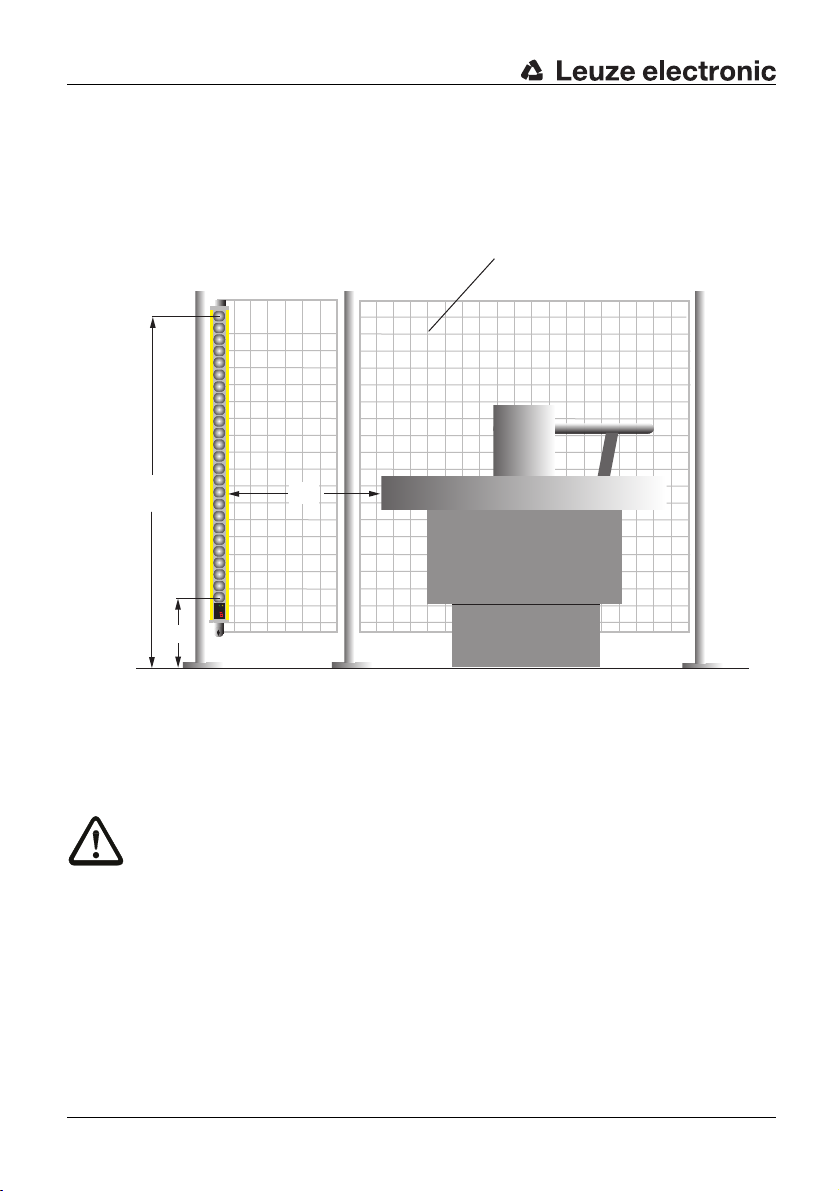
6.1.1 Safety distance for point of operation guarding
Calculation of the safety distance for a SOLID-4 Safety Light Curtain with resolution of 14,
20, 30 or 40 mm for point of operation guarding:
The safety distance "S" for point of operation guarding is calculated in accordance with EN
999 with t
S [mm] = K [mm/s] x T [s] + C [mm]
26 SOLID-4 Leuze electronic
he formula:
Page 27

S = Safety distance in mm
f
d
b
a
e
c
the result is less than 100 mm, a distance of at least 100 mm must still be maintained.
If
K = Approach speed in mm/s
In the close area of 500 mm, 2,000 mm/s is used for the calculation. If the distance is greater than 500 mm, K = 1,600 mm/s can be used for the calculation. In this case, however, a
minimum of 500 mm applies for the safety distance.
T = Total delay time in seconds;
total from:
The response time of the protective device, t
The response time of the safety interface, if any, t
The machine’s stopping time, t
Machine
c)
a)
AOPD
Safety interface
b)
C = 8 x (d-14) in mm
Additional amount depending on the depth of penetration into the protective field before
turning on the AOPD
d = Resolution of the AOPD
a)
See Chapter 11.2
b)
See safety interface technical data
c)
See technical data of the machine or stopping time measurement
Installation
DEUTSCHENGLISHFRANÇAISITALIANOESPAÑOLNEDERLANDS
a = Safety distance (S)
b = Measures to prevent penetration from above
c = Measures to prevent penetration from the sides
d = Measures to prevent penetration from the rear
e = Measures to prevent penetration from below
Fig. 6.1-1: Safety distance (a) for point of operation guarding
*) If this value cannot be achieved because of the safety distance, other measures, e.g. mechanical
barriers, must guarantee the required maximum distance of 75 mm.
f = 75 mm – Maximum distance to avoid walking behind*
TNT 35/7-24V
Warning!
≤
If AOPDs with additional control functions are used, the resolution must be
minimum distance must be S
≥
150 mm.
30 mm and the
S [mm] = 2000 [mm/s] x (t
AOPD
+ t
Safety interface
+ t
) [s] + 8 x (d-14) [mm]
Machine
Leuze electronic SOLID-4 27
Page 28

Installation
a
c
d
Calculation example for point of operation guarding:
DEUTSCH ENGLISH FRANÇAIS ITALIANO ESPAÑOL NEDERLANDS
6.1.2 Safety distance for danger zone guarding
A Safety Light Curtain with a resolution of 20 mm, protective field height 1500 mm is used
on a machine wit
h a stopping time of 150 ms. The response time of the safety interface is
20 ms.
Stopping time of the machine t
Response time t
Response time t
= 25 ms
AOPD
Safety interface
Machine
= 20 ms
Resolution d of the AOPD = 20 mm
T = 0.150 s + 0.025 s + 0.020 s = 0.195 s
S = 2000 x 0.195 + 8 x (20 -14) =
Warning!
Make certain during assembly that it is not po
walk behind the protective device.
Calculation of the safety distance and required resolution for a Safety Light Curtain for
danger zone guarding.
= 150 ms
438 mm
ssible t
o reach over, around or under or to
a = Safety distance (S)
b = Measures to prevent access from the sides
c = Height above floor
d = 50 mm – Maximum distance to avoid walking behind*
Fig. 6.1-2: Safety distance (a) and height (c) for danger zone guarding
*) If this value cannot be achieved because of the safety distance, other measures, e.g. mechanical
barriers, must guarantee the required maximum distance of 50 mm. From 375 mm height above the
floor 75 mm are permissible.
28 SOLID-4 Leuze electronic
Page 29
Installation
The height of the protective field H above the reference plane and the resolution d of the
AOPD are related to each other as follows:
H
[mm] = 15 x (d -50) [mm] or d [mm] = H
min
H
= Minimum height of the protective field above the reference plane,
min
maximum height = 1000 mm
Heights equal to or less than 300 mm are considered too low for adults to crawl
under
d = Resolution of the AOPD
/15 + 50 [mm]
min
DEUTSCHENGLISHFRANÇAISITALIANOESPAÑOLNEDERLANDS
The safety distance "S" for danger zone guarding is
ed in accordance with EN 999
calculat
using the formula:
S [mm] = K [mm/s] x T [s] + C [mm]
S = Safety distance in mm
K = Approach speed of 1600 in mm/s.
T = Total delay time in seconds;
total from:
The response time of the protective device, t
The response time of the safety interface, if any, t
The machine’s stopping time, t
Machine
c)
a)
AOPD
Safety interface
C = (1200 mm – 0,4 H), but not less than 850 mm (arm’s length)
H = Height of the protective field above the floor
a)
See Chapter 11.2
b)
See safety interface technical data
c)
See technical data of the machine or stopping time measurement
S [mm] = 1600 [mm/s] x (t
AOPD
+ t
Safety interface
+ t
) [s] + (1200-0.4 H) [mm]
Machine
b)
TNT 35/7-24V
Leuze electronic SOLID-4 29
Page 30
Installation
a
d
c
b
6.1.3 Safety distance and beam heights for Safety Light Curtains as access
DEUTSCH ENGLISH FRANÇAIS ITALIANO ESPAÑOL NEDERLANDS
guarding
Determination of the beam heights and calculation of the safety distance of Safety Light
Curtains with a resolution of 14, 20, 30 or 40 mm for use as access guarding, for example
with l
imited space between the protective field and point of operation.
a = Safety distance (protective field/point of operation)
b = Height of the lowest beam above the reference level, see table 6.1-1
c = Height of the highest beam, see table 6.1-1
d = Measures to prevent access from the sides
Fig. 6.1-3: Access guarding with Safety Light Curtain, resolution of 14, 20, 30 or
40 mm
Warning!
Please also observe the additional safety instructions for access guarding with SOLID-4 in
Chapter 2.7.
30 SOLID-4 Leuze electronic
Page 31

Installation
Beam heights with use of Safety Light Curtains for access guarding in accordance
with EN 999 and EN ISO 13857:
Version Resolu-
tion
SD4-14-hhhh 14 mm As per EN ISO 13857 As per EN ISO 13857 0 mm
SD4-20-hhhh 20 mm As per EN ISO 13857 As per EN ISO 13857 48 mm
SD4-30-hhhh 30 mm As per EN ISO 13857 As per EN ISO 13857 128 mm
SD4-40-hhhh 40 mm As per EN ISO 13857 As per EN ISO 13857 208 mm
SD4-90-hhhh 90 mm 300 mm 1200 mm 850 mm
Lowest beam above
reference plane
Highest beam above
reference plane
Additional
amount C
(see formula)
DEUTSCHENGLISHFRANÇAISITALIANOESPAÑOLNEDERLANDS
Table 6.1-1: Beam height
s above the reference plane and additional amount C for
access guarding applications
Calculation formula for safety distance S based on EN 999:
Calculation of the safety distance for a Safety Light Curtain with a resolution of up to 40
mm
, used for access guarding. The safety distance S is calculated as per EN 999
according to the formula:
S [mm] = K [mm/s] x T [s] + C [mm]
S = Safety distance in mm
K = Approach speed in mm/s
In the close area of 500 mm, 2,000 mm/s is used for the calculation. If the dis-
s
tance is greater than 500 mm, K = 1,600 mm/
can be used for the calculation.
In this case, however, a minimum of 500 mm applies for the safety distance.
T = Total delay time in seconds;
total from:
The response time of the protective device, t
The response time of the safety interface, if any, t
c)
The machine’s stopping time, t
Machine
a)
AOPD
Safety interface
b)
C = 8 x (d-14) in mm
Additional amount depending on the depth of penetration into the protective field
before t
urning on the AOPD
d = Resolution of AOPD up to a maximum of 40 mm
a) See Chapter 11.2
b) See technical data of the safety interface
c) See technical data of the machine or stopping time measurement
S [mm] = 2000 [mm/s] x (t
AOPD
+ t
Safety interface
+ t
) [s] + 8 x (d-14) [mm]
Machine
TNT 35/7-24V
Leuze electronic SOLID-4 31
Page 32

Installation
a
c
b
If the resolution is greater than 40 mm, for example for SOLID-4 Safety Light Curtains with
DEUTSCH ENGLISH FRANÇAIS ITALIANO ESPAÑOL NEDERLANDS
6.1.4 Minimum distance from reflective surfaces
a resolution of 90 mm, an additional amount is required:
C = 850 mm (arm’s length)
The safety distance with 90 mm is therefore calculated according to the following formula:
S [mm] = 1600 [mm/s] x (t
AOPD
+ t
Warning!
Please also observe the additional safety instructions for access guarding with SOLID-4 in
Chapter 2.7.
Warning!
When using access guarding, it must be ensured that t
active and that unlocking from inside the danger zone is not possible.
Warning!
Reflective surfaces near optical protective devices c
beams into the receiver. This can cause an object in the protective field not to be detected!
Therefore, all reflective surfaces and objects (material containers, cans, etc.) must be kept
at a minimum distance from the protective field. The minimum distance depends on the
distance "b" between the transmitter and the receiver.
Safety interface
+ t
Machine
) [s] +850 [mm]
he start/restart interlock function is
an indirectly deflect the transmitter's
a = Distance
b = Protective field width
c = Reflective surface
Fig. 6.1-4: Minimum distances from reflective surfaces
With the calculation of the minimum distance to reflective surfaces it must be ensured that
wit
h
a protective field width of 3 m or less, at least a minimum distance of 131 mm is
achieved.
using the
With protective field widths over 3 m the minimum distance "a" is calculated
following formula:
a [m] = 0.044 x b [m]
32 SOLID-4 Leuze electronic
Page 33

a = Distance [mm]
130
b
a
b = Protective field width [m]
Fig. 6.1-5: Minimum distances from reflective surfaces as a function of the width of
the protective field
6.2 Mounting notes
Special notes on mounting a SOLID-4 Safety Light Curtain for point of operation
guarding:
➢ Calculate the safety distance according to the formula in Chapt
➢ Ensure that it is impossible to reach under, over,
Curtain.
➢ Observe the maximum distance between machine table and protective field of 75 mm,
h reference to a table height of 750 mm. If this is not possible because the safety
wit
distance is too big, a mechanical barrier must be provided.
➢ Observe the minimum required distance to reflective surfaces.
Installation
DEUTSCHENGLISHFRANÇAISITALIANOESPAÑOLNEDERLANDS
er 6.1.1.
around or walk behind the Safety Light
TNT 35/7-24V
Leuze electronic SOLID-4 33
Page 34
Installation
DEUTSCH ENGLISH FRANÇAIS ITALIANO ESPAÑOL NEDERLANDS
Special notes on mounting a SOLID-4 Safety Light Curtain for danger zone guarding:
➢ Calculate the safety distance according to the formula in Chapt
determines the minimum height of the protective field above the floor.
➢ Ensure that the maximum height of the protective field above the reference plane of
1000 mm
impossible for an adult to crawl under (also see EN 999).
➢ It must not be possible to step into the danger zone from the sides. Suitable hard guards
must
➢ When mounting the device, ensure that it is impos
optical components (thereby allowing entrance into the danger zone).
Note!
Positioning behind corresponding cutouts on the hard
stepping onto transmitter or receiver housings.
is not exceeded and only heights equal to or less than 300 mm are considered
be provided.
sible to pass onto the housings of the
er 6.1.2. The resolution
guards on the sides prevents
➢ Consider the
stand undetected between this light beam and the machine.
Special notes on mounting a SOLID-4 Safety Light Curtain for access gu
➢ Calculate the safety distance according to the formula in Chapter 6.
➢ The highest and the lowest light beam and therefore the height of the protective field for
ety Light Curtains with a resolution of 14, 20, 30 or 40 mm is determined by the
Saf
requirements in acc. with EN ISO 13857.
➢ Access guarding may only be operated with the start/restart interlock function. Activate
t
he internal RES interlock function of the SD4R-E or the RES interlock function of the
downstream interface and check their effectiveness.
➢ Ensure while installing the start/restart button, that it is impossible to press this button
f
rom inside the danger zone. Make sure that the complete danger zone can be seen from
the location of the button.
position of the last light beam before the machine. It must not be possible to
6.3 Mechanical mounting
What should generally be taken into consideration during installation?
➢ Ensure that transmitter and receiver are mounted on an even surface at the same height.
➢ Use screws
➢ Fix the transmitter and receiver in position so that they cannot be shifted. Securing
ransmitter and receiver so they cannot be moved or swiveled is especially important in
t
the close area with a narrow protective field.
➢ The connections of transmitter and receiver must be pointing in the same direction.
➢ The safety distance between the protective field and the point of operation must be
observ
➢ Ensure that access to the point of operation/
protective field. Additional access points must be guarded separately (e.g. by hard
guards, additional Light Curtains or doors with locking devices).
for mounting that can only be loosened with a tool.
ed.
arding:
1.3.
danger zone is only possible through the
34 SOLID-4 Leuze electronic
Page 35

6.4 Mounting types
6.4.1 Standard mounting
Four brackets that can rotate 360° (two each for transmitter and receiver) are included with
delivery.
Installation
DEUTSCHENGLISHFRANÇAISITALIANOESPAÑOLNEDERLANDS
Fig. 6.4-1: 360° rot
ation bracket, mounting examples
6.4.2 Option: Mounting with swiveling brackets
Four swivel mounting brackets with shock absorbers can be ordered optionally. They are
not included with delivery. The swivel range is ± 8°.
Fig. 6.4-2: Swiveling bracke
t with shock absorber
TNT 35/7-24V
Leuze electronic SOLID-4 35
Page 36

Installation
6.4.3 Option: Side mounting
DEUTSCH ENGLISH FRANÇAIS ITALIANO ESPAÑOL NEDERLANDS
Mounting is optionally possible with mounting brackets with sliding nuts on the side slot.
They are not included with delivery.
L-mounting bracket Z-mounting bracket
Fig. 6.4-3: Mounting examples, L-mounting bracket and Z-mounting bracket
36 SOLID-4 Leuze electronic
Page 37

7 Electrical connection
FE
2
• The electrical connection must be performed by experienced personnel. Knowledge of all
safety notes contained in these operating instructions is part of this competence.
• The external supply voltage of 24 V DC +/- 20% must guarantee safe isolation from the
ns voltage in accordance with IEC 60742 and be able to bridge a power outage
mai
period of at least 20 ms. Leuze electronic offers suitable power supplies (see list of
acc
ssories in the Appendix Chapter 12). Transmitters and receivers must be supplied
e
from a shared power supply and must
• Basically both safety switching outputs OSSD1 and OSSD2 must be looped into the
king circuit of the machine.
wor
• Signal outputs may not be used for switching safety-relevant signals.
• The start/restart button for unlocking the restart interlock must be mounted in such a way
at it cannot be reached from the danger zone and the entire danger zone is fully visible
th
from its installation position.
• It is vital during the electrical installation that the power of the machine or system to be
protect
ed is switched off and locked, so that the dangerous movements cannot be
started unintentionally.
7.1 M12 coupling
Transmitter and receiver are equipped with an M12 coupling; the transmitter with a 5-pin
M12 coupling and the receiver with an 8-pin M12 coupling.
Warning!
To ensure safe operation of the SOLID-4, onl
Chapter 12.3 – Accessories may be used.
Electrical connection
used against overcurrent (see Chapter 7.2).
be f
y the connecting cables listed in
DEUTSCHENGLISHFRANÇAISITALIANOESPAÑOLNEDERLANDS
7.1.1 Transmitter
Fig. 7.1-1: SD4T 5-pin (view of the pins)
Leuze electronic SOLID-4 37
TNT 35/7-24V
Page 38

Electrical connection
FE
DEUTSCH ENGLISH FRANÇAIS ITALIANO ESPAÑOL NEDERLANDS
Pin Cable
1 Brown Supply voltage 24 V DC for TC1 and 0 V for TC2
2Whitenc
3 Blue Supply voltage 0 V for TC1 and 24 V DC for TC2
4 Black Test in Test input
5 Gray Device internally
Mounting
plug
housing
Table 7.1-1: Transmitter, connection assignment
The polarity of the power supply from Pin1 and Pin3 determines the selected optical
transmission channel. If 24 V DC is present on Pin1 and 0 V on Pin3, transmission
channel 1 is selected. If 0 V is present on Pin1 and 24 V DC on Pin3, transmission
channel 2 is selected.
Note!
Make certain you select the same transmission channel for both, for transmitter and
recei
For optimum shielding, connecting cables with which t
of the housing coupling must be used (suitable cables are listed under accessories in
Chapter 12.3).
colors
Braided
shield
er.
v
Assignment Inputs/outputs
Connected to 24 V DC
→ Normal operation
to 0 V or free
→ External test activated
Functional earth
wired on housing
Shield Functional earth
he shield is routed on the knurled nut
7.1.2 Receiver SD4R-E
Fig. 7.1-2: SD4R-E 8-pin (view of the pins)
38 SOLID-4 Leuze electronic
Page 39

Electrical connection
Pin Color Assignment Function
1 White Input:
2 Brown Supply voltage 24 V DC for TC 1 and 0 V for TC 2
3 Green Input:
4 Yellow Input:
5 Gray Output OSSD1, transistor switching output
6 Pink Output OSSD2, transistor switching output
7 Blue Supply voltage 0 V for TC 1 and 24 V DC for TC 2
8 Red Device internally
Mounting
plug housi
Table 7.1-2: SD4R-E
ng
Braided
shield
Start/restart
Signal output:
Weak signal/
erro
r
Operating
m
feedback
ode/
circuit, EDM
Operating mode
wired on
hous
i
ng
Shield Functional earth
Receiver connection assignment
Start/restart normally open contacts
against
24
Weak signal/error:
24 V DC light reception, strong,
0 V light reception weak or error
Contactor monitoring (EDM):
24 V DC: Without EDM
0 V: With EDM and FC closed
High impedance: With EDM and FC open
Start/restart interlock
(RES):
24 V DC: With RES
Jumper to Pin1: Without RES (note: signal
out
Functional earth
V DC
put
remains functional)
DEUTSCHENGLISHFRANÇAISITALIANOESPAÑOLNEDERLANDS
7.1.2.1 Transmission channel selection
The polarity of the power supply from Pin2 and Pin7 determines the selected optical
transmission channel.
If 24 V DC is present on Pin2 and 0 V on Pin3, transmission channel 1 is selected. If 0 V is
pres
on Pin2 and 24 V DC on Pin7, transmission channel 2 is selected.
ent
Note!
Make sure that you select the same transmission channel for both transmitter and receiver.
For optimum shielding, connecting cables with which
of the housing coupling must be used (suitable cables are listed under accessories in
Chapter 12.4).
Leuze electronic SOLID-4 39
the shield is routed on the knurled nut
TNT 35/7-24V
Page 40

Electrical connection
7.1.2.2 Operating mode selection, start/restart interlock (RES) and contactor
DEUTSCH ENGLISH FRANÇAIS ITALIANO ESPAÑOL NEDERLANDS
monitoring (EDM).
The SD4R-E Receiver must be connected via an 8-pin M12 coupling. The RES/EDM
functions can be activated via the operating mode selections, Pin3 and Pin4.
Warning!
The operating mode switchover must only be made in the switched-off state. Operating
mode swit
removed by interrupting the voltage supply.
Pin3 24 V DC 24 V DC 0 V via closed feed-
Pin4 Jumper to Pin1 24 V DC Jumper to Pin1 24 V DC
Note on
Pin
Table 7.1-3: S
chovers (RES/EDM) during operation cause a fault (F32/F33), which can only be
1
Without EDM
Without RES
Signal output,
weak signal/
LID-4 SD4R-E Receiver operating mode selection
O
Without EDM
With RES
Start button, nor-
error
mally open contact to 24 V DC
and signal out
weak signal/error
With EDM
Without RES
back circuit
Signal output, weak
signal/
er
ut,
p
ror
With EDM
With RES
0 V via closed feedback circuit
Start button, normally open contact
to 2
4 V DC and
signal output
weak signal/error
,
40 SOLID-4 Leuze electronic
Page 41

7.1.3 Receiver SD4R
FE
2
Electrical connection
DEUTSCHENGLISHFRANÇAISITALIANOESPAÑOLNEDERLANDS
Fig. 7.1-3: SD4R 5-pin (view of
Pin Color Assignment Function
1 Brown Supply voltage 24 V DC
2 White Output OSSD1, transistor switching output
3 Blue Supply voltage 0 V
4 Black Output OSSD2, transistor switching output
5 Gray Device internally
Mounting
plug housi
Table 7.1-4: SD4R Receiver
Notice!
When using an SD4R receiver, make certain to select transmission channel 1 on the
esponding transmitter.
corr
For the best-possible shielding, use connecting cabl
knurled nut of the housing coupling (suitable cables are listed under accessories,
Chapter 12.4).
ng
Braided
shield
he pins)
t
wired on
hous
ng
i
Shield Functional earth
connection assignment
Functional earth
es on which the shield extends to the
TNT 35/7-24V
Leuze electronic SOLID-4 41
Page 42
Electrical connection
1
2
3 4
5
1
2 3
4
5
k1
k2
SOLID-4
SD4R-E
SOLID-4
SD4T
K1
K2
+24 V DC
GND
FE
nc
F
6 7
8
k1 k2
k1
k2
e
f
h
g
f
f
a
b
d
c
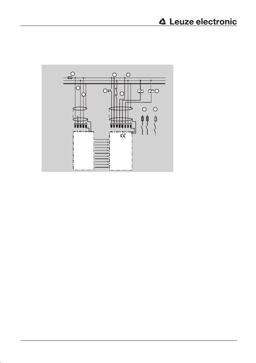
7.2 Connection examples
DEUTSCH ENGLISH FRANÇAIS ITALIANO ESPAÑOL NEDERLANDS
7.2.1 Connection example for transmission channel 1(TC1)
a = EDM feedback circuit
b = Positive-driven relays, spark suppression is pro-
vided by the receiver
c = Release circuit, 2-channel*
d = Release circuit, 1-channel*
e = External testing selected
f = Polarity for transmission channel 1
g = Start/restart button
h = 2 A fine-wire fuse, melting fuse
*) Always use both of the contacts in the release circuit; protect against overcurrent.
Fig. 7.2-1: SD4R-E Receiver, TC 1, with RES, with EDM
42 SOLID-4 Leuze electronic
Page 43

Electrical connection
1
2 3 4 5
1
2 3 4 5
k1
k2
SOLID-4
SD4R-E
SOLID-4
SD4T
K1
K2
+24 V DC
GND
FE
nc
f
F
6
7 8
k1
k2
k1
k2
h
e
g
f
f
a
c d
b
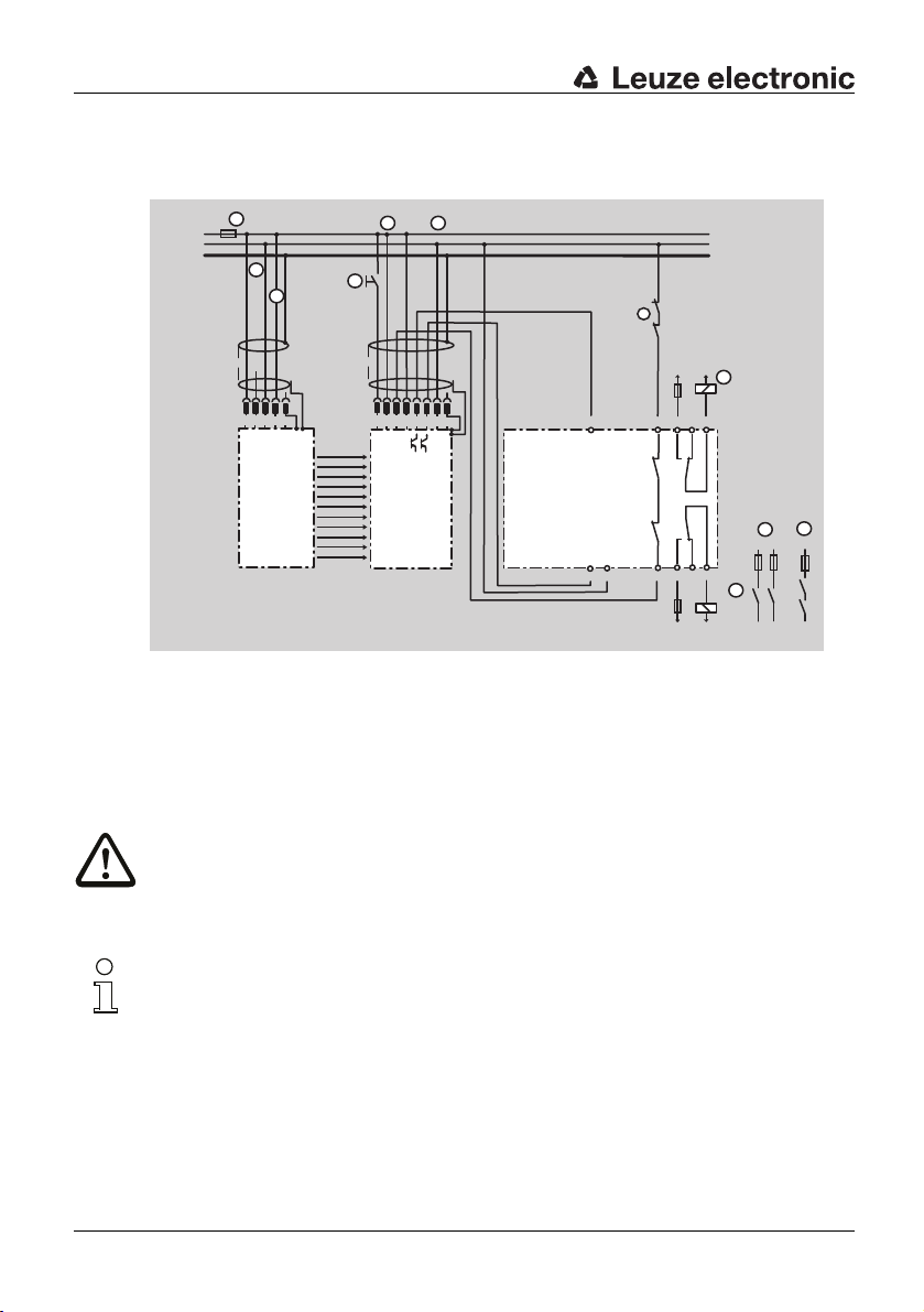
7.2.2 Connection example for transmission channel 2 (TC2)
When selecting TC 2, the polarity of the supply voltage on the transmitter and the receiver
must be reversed.
DEUTSCHENGLISHFRANÇAISITALIANOESPAÑOLNEDERLANDS
a = EDM feedback circuit
b = Positive-driven relays, spark suppression is
provi
c = Release circuit, 2-channel*
ded by the receiver
d = Release circuit, 1-channel*
e = External testing selected
f = Polarity for transmission channel 2
g = Start/restart button
h = 2 A fine-wire fuse, melting fuse
*) Always use both contacts in the release circuit.
Fig. 7.2-2: SD4R-E Receiver, TC2, with RES, with EDM
Leuze electronic SOLID-4 43
TNT 35/7-24V
Page 44
Electrical connection
1
2 3
4
5
1
2
3 4 5
SOLID-4
SD4R-E
SOLID-4
SD4T
+24 V DC
GND
FE
nc
6 7 8
K5
K4
k4 k5
k5
k4
k5
k4
a
Y1
Y2
B3
A2
B1
14
12
11
24
2221
L+PhL-
N
F
h
L+
Ph
LN
MSI-RM2
f
e
g
f
f
b
b
c d
7.2.3 SOLID-4 connection example
DEUTSCH ENGLISH FRANÇAIS ITALIANO ESPAÑOL NEDERLANDS
with downstream relay module, MSI-RM2
a = EDM feedback circuit
b = Positive-driven relays, spark suppression
required
c = Release circuit, 2-channel*
*) Always use both contacts in the release circuit.
Fig. 7.2-3: SD4R-E Receiver, TC1, with RES, with EDM and MSI-RM2
d = Release circuit, 1-channel*
e = External testing selected
f = Polarity for transmission channel 1
g = Start/restart button
h = 2 A fine-wire fuse, melting fuse
Warning!
If K4 and K5 are installed in the same switching rack as the MSI-RM2, each relay must be
44 SOLID-4 Leuze electronic
ed via a separate connecting cable with the MSI-RM2. The connecting cables must
connect
be routed in a strong conduit so that mechanical damage is prevented. Also be sure to
follow the MSI-RM2 connection and operating instructions.
Note!
Additional functions such as Muting or Cycle
safety interfaces of the MSI series from Leuze electronic. For this, see accessories in
Chapter 12.3.
trol can be implemented with intelligent
Con
Page 45

Electrical connection
SOLID-4 / SD4R
+24V
+24V
Test
OSSD1
SOLID-4 / SD4T
OSSD2
0V
FE
FE
0V
Var. B
Var. A
4
142
-A1
1 234
-A2
1 2
3
14
-W1 -W2
5
-W2
SH3
-W1
5
SH3
-K3 -K4-K4
-K3
0V
PE
+24V
PE.
+24V
0V.
n.c.
14 24 42
13 23 41
A1
A2
-K3
121
2
L+ L+
L- L-
-S1
-K3
-K4
+24V
0V
MSI-SR4
A1
-A3
A2
S22 S12 S31 S33 S34 S35
2 AOPD-
1 AOPD+
33
34
A1
A2
-K4
2 AOPD+
IV-0
RES-0
RES-I
1
2
*
*
7.2.4 Connection example of SOLID-4 with downstream MSI-SR4 Safety Interface Device
Figure 7.2-4:Rec
Attention!
If K3 and K4 are installed in the same switching rack as the MSI-SR4, each relay must be
ed via a separate connecting cable with the MSI-SR4. The connecting cables must
connect
be routed in a strong conduit so that mechanical damage is prevented. Also be sure to
follow the MSI-SR4 connection and operating instructions.
e
iver SD4R with MSI-SR4
DEUTSCHENGLISHFRANÇAISITALIANOESPAÑOLNEDERLANDS
Leuze electronic SOLID-4 45
TNT 35/7-24V
Page 46

Startup
8 Startup
DEUTSCH ENGLISH FRANÇAIS ITALIANO ESPAÑOL NEDERLANDS
Warning!
Before starting up the SOLID-4 on a power-driven production machine for the first time, an
experienced and
and the integration of the opto-electronic protective device into the machine control system.
Before switching on the supply voltage for the first time and while the transmitters and
receiver
protective device do not have any effect on the machine. The switching elements that
finally set the dangerous machine in motion must be safely switched off and secured from
restarting.
The same precautionary measures apply after
of the optical protective device, after repairs or during maintenance work.
Only after it has been determined that the optical protect
be integrated into the machine's control circuit!
8.1 Switching on
Warning!
Without internal start/restart interlock function and with free protective field the OSSDs
im
commissioned person with suitable training must check the entire setup
s are being al
mediately switch to the ON state!
igned, it must also be ensured that the outputs of the optical
each c
hange in parameter-based functions
ive device functions correctly can it
Make sure that the transmitter and receiver are prot
see Chapter 7.2). There are special requirements for the supply voltage: The power supply
must guarantee secure mains supply isolation, have a load current reserve of at least
250 mA and be able to bridge a power outage for at least 20 ms.
ected against overcurrent (for fuse size
8.1.1 Display sequence with SD4T Transmitter
After the power supply is turned on and the self-test is completed, the LEDs indicate the
current operating status (see Chapter 5.1).
Warning!
If the transmitter signals with error display (LED1 lights permanently red/LED2 any display),
the 24
V DC supply voltage and the wiring must be checked. If the error remains after it is
tu
rned on again, stop the startup process immediately and send in the defective transmitter
to be checked.
46 SOLID-4 Leuze electronic
Page 47

8.1.2 Display sequence with SD4R-E Receiver
After the device is turned on, "8." appears for a few moments on the transmitter display
followed by an "S" for about 1.5 seconds for the self test. The display then switches and
permanently shows the selected transmission channel, "1" or "2".
Startup
Warning!
If the receiver signals with the error display, the 24 V DC supply voltage and the wiring
m
st be checked. If the display remains after it is turned on again, stop the startup process
u
immediately and send in the defective receiver to be checked.
The displays of the receiver LEDS after switching on: without start/restart interlock function
(RE
, FS).
S
Warning!
The receiver switches to the ON-state as soo
LED Without internal RES, transmitter/re-
LED1 Green = ON-state of the
LED2 No display = RES not locked No display = RES not locked
Table 8.1-1: LED displays,
The LED displays of the SD4R-E Receiver with a
function after it is turned on (for activation see Chapter 7.1.2):
LED With internal RES, before unlocking
LED1 Red = OFF state of the
LED2 Yellow = RES locked No display = RES locked
Table 8.1-2: LED displays,
ceiver aligned and protective field free
OSSDs
receiver SD4R-E with start/restart interlock not activated
(RES)
with the start/restart button while the
protective field is free
OSSDs
receiver SD4R-E with start/restart interlock activated (RES)
n as it receives all beams!
Without internal RES, transmitter/receiver not aligned or protective field
no
t free
Red = O
ctivated internal start/restart interlock
With internal RES, before unlocking
with the start/restart button while the
protective field is interrupted
Red = O
FF state of the
OSSDs
FF state of the
OSSDs
DEUTSCHENGLISHFRANÇAISITALIANOESPAÑOLNEDERLANDS
TNT 35/7-24V
LED With internal RES, after unlocking
LED1 Green = ON-state of the
LED2 No dis
Table 8.1-3: LED displays,
Leuze electronic SOLID-4 47
with the start/restart button while the
protective field is free
OSSDs
play = RES unlocked
receiver SD4R-E with start/restart interlock activated (RES)
Page 48

Startup
8.1.3 Display sequence on receiver SD4R
DEUTSCH ENGLISH FRANÇAIS ITALIANO ESPAÑOL NEDERLANDS
After switch-on, "8." appears on the transmitter display for a few moments followed by an
"S" for approx. 1.5 sec. indicating a self test. The display then switches and constantly
displays the selected transmission channel, either "1" or "2".
Attention!
If the receiver responds with the error display, the 24 V DC connection voltage and wiring
are t
be inspected. If the display persists after switching on again, immediately interrupt
o
start-up and return the defective receiver to us for inspection.
The displays on the receiver LEDs after switch-on:
Attention!
As soon as the receiver receives all beams, it switches to the ON state!
LED Transmitter/receiver aligned and pro-
LED1 green = ON-state of the OSSDs red = OFF-state of the OSSDs
Table 8.1-4: LED display
tective field clear
– receiver SD4R
Transmitter/receiver not aligned or
protective field not clear
8.2 Aligning transmitter and receiver
Transmitter and receiver must be at the same height or, if installed in a horizontal position,
be at the same distance from the reference surface and lightly fastened at first. The narrow
specified angle of beam spread of ± 2° requires increased precision in aligning the two
components with each other before the devices are screwed firmly into place.
Note!
If cascaded AOPDs are aligned with each other, it must
then guest.
8.2.1 Optimizing alignment by turning and/or tilting the transmitter and receiver
The difference between free protective field (display shows the numbers of the transmission channel) and weak signal (channel number flashes on t
optimization.
If the components are already aligned, it is recomm
e.g. by turning the receiver. Turn the receiver with slightly loosened brackets until the 7segment display starts to flash. Take note of the position. Now turn the receiver in the
opposite direction until the display lights constantly and further, until it flashes again. Now
turn the receiver back in between the two positions determined. Screw the receiver firmly
into place to prevent turning. Now do the same with the transmitter.
For cascaded systems, the procedure can be performed for all transmitters and receivers
one af
er the other, beginning with the host. A precise preliminary alignment of all
t
components is also required here.
ended that you optimize the alignment,
be in the order of host first,
always
he display) enables alignment
48 SOLID-4 Leuze electronic
Page 49

9 Testing
9.1 Testing before first startup
Testing by an experienced technician before first startup must ensure that the optical
protective device and any other safety components that might be present have been
selected in accordance with local regulations and applicable European Directives, especially the European Machine and Work Equipment
required protection when properly operated.
➢ Use the regulations listed above, where required,
in the Appendix of these instructions, to check that the protective devices are properly
installed, that they are properly wired into the controls and that they work in all machine
operating modes. When selecting the checklist, note the type of protection (point of
operation, danger zone or access guarding).
➢ T
he same testing requirements apply if the machine in question has not been operated
f
or a longer period of time and after major modifications or repairs if this could affect the
safety of the machine.
➢ Observe the specifications regarding the i
enced technicians before work is started. Instruct
machine owner.
The results of this test are documented for the machine owner in accordance with
ISO
9000 ff.
9.2 Regular tests
Regular tests must also be carried out in accordance with local regulations. These are
designed to discover changes (e.g. in stopping times) or manipulations to the machine or
protective device.
➢ You
must have the effectiveness of the protect
technician at suitable intervals, but at least once a year.
➢ The applicable checklist in the Appendix may also be used during regular testing.
e electronic also provides a specialist serv
Leuz
Testing
Direct
ive and that they provide the
with the help of the checklists provided
nstructing of operation personnel by experi-
ing personnel is the responsibility of the
ive device checked by an experienced
ice for regular tests.
DEUTSCHENGLISHFRANÇAISITALIANOESPAÑOLNEDERLANDS
9.3 Daily testing with the test rod
SOLID-4 are self-monitoring Safety Light Curtains. Nevertheless it is very important to
check the effectiveness of the protective field every day to be sure that the protection also
remains effective at every point after a parameter or tool change.
Warning!
Never use your fingers, hand or arm for checking the system!
Leuze electronic SOLID-4 49
TNT 35/7-24V
Page 50
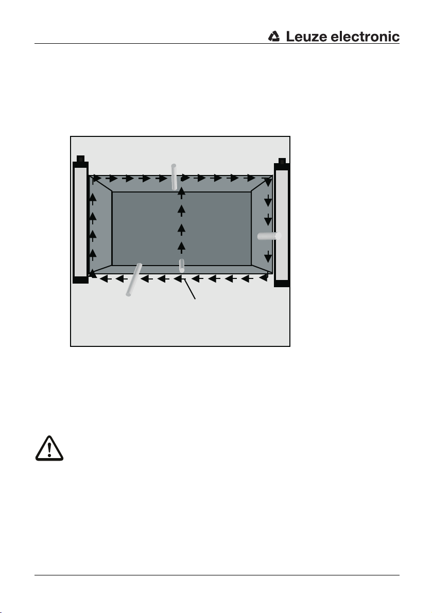
Testing
a
DEUTSCH ENGLISH FRANÇAIS ITALIANO ESPAÑOL NEDERLANDS
➢ When selecting the test rod, use the identification plate of the receiver with the resolution
information as a guideline.
➢ If the internal start/restart interlock function is selected, but the AOPD is released, LED1
l
ights up green on the SD4R-E Receiver. When the test rod is inserted, LED1 switches to
red, and the restart interlock locks. During the testing procedure, LED2 must not light up
at any position of the protective field. Only after the test rod has been taken out of the
protective field does LED2 light up yellow (restart interlock locked).
a = Test start
Fig. 9.3-1: Testing the protective field with the test rod
➢ I
f the AOPD is being operated without the internal start/restart interlock, it is sufficient to
wat
ch LED1 on the receiver during the testing procedure. When the test rod is inserted
into the protective field, this LED1 must switch from "green" to "red" and must not switch
back to "green" at any point during the test.
Warning!
If the test does not provide the desired result, the cause could be a protective field height
t
is too low or reflections from reflective metals or tools brought into the area. In this
hat
case the installation of the Safety Light Curtain must be checked by a specialist. If the
cause cannot be clearly defined and remedied, the machine or system may not be used!
50 SOLID-4 Leuze electronic
Page 51

9.4 Cleaning the front screens
The front screens on the transmitters and receivers must be cleaned regularly depending
on how dirty they are. A flashing 7-segment display with the protective field free (LED1 is
green) indicates a "weak signal reception"; cleaning the front screen is then required. If
cleaning the screens does not improve this, the range and alignment must be checked. We
recommend using a mild cleanser for cleaning the Plexiglas front screens. The screens are
resistant to diluted acids or alkalis and resistant to organic solvents within limits.
Testing
DEUTSCHENGLISHFRANÇAISITALIANOESPAÑOLNEDERLANDS
Leuze electronic SOLID-4 51
TNT 35/7-24V
Page 52

Troubleshooting
10 Troubleshooting
DEUTSCH ENGLISH FRANÇAIS ITALIANO ESPAÑOL NEDERLANDS
10.1 What do I do if an error occurs?
10.2 Diagnostics
10.2.1 SD4T Transmitter diagnostic
The following information is used for rapid troubleshooting in the event of a malfunction.
If the AOPD shows an error on the display, the machine must be stopped immediately and
checked by an experienced technician. If it is determined that the error cannot be clearly
defined and remedied, your local Leuze office and or the Leuze electronic hotline can
assist.
Operational malfunctions often have simple causes that you can remedy yourself. The
following tables will help you do this.
Symptom Activity for removing errors
LED is not lit Check supply voltage
LED1 is lit red
c
inuously
ont
LED2 is lit red
cont
inuously
Table 10.2-1: T
Check connecting cable
Replace transmitter if necessary
Hardware error, replace transmitter
Transmitter in test mode
Check test input, connect to 24 V DC
ansmitter diagnostics
r
10.2.2 SD4R-E Receiver diagnostics
The receiver displays faults and errors with Fxx codes. All possible codes and corresponding activities are then performed.
Code Cause/significance Activity for removing errors
LEDs and 7-segment displays are not lit 24 V DC supply voltage, check connect-
F4 Internal hardware fault Send the device in
F6* Short circuit between ground and
F7 OSSD short circuit after VCC or cross
F8* Short circuit between ground and
*) Locking error - a system reset is only achieved by switching the supply voltage off and on.
52 SOLID-4 Leuze electronic
SD1 or cross circuit
OS
circ
t, output 1
ui
O
SD2 or cross circuit
S
ing cable,
replace the receiver if necessary
Remove short circuit between ground,
overload or cross circuit; turn supply voltage off and on again
Remove short circuit after VCC or cross
circuit; if it occurs again, send the device
in
Remove short circuit between ground,
overload or cross circuit; turn supply voltage off and on again
Page 53

Troubleshooting
Code Cause/significance Activity for removing errors
F9 OSSD short circuit after VCC or cross
ci
rcuit, output 2
F10 Undervoltage on power supply Check power supply and feed
F20 Internal hardware fault Send the device in
F21 Internal hardware fault Send the device in
F22 Internal hardware fault Send the device in
F23 Internal hardware fault Send the device in
F24 Internal hardware fault Send the device in
F25* Different transmission channels discov-
ered (during operation)
F26* Different evaluation procedures (SCAN)
F27 Internal hardware fault Send the device in
F28 Internal hardware fault Send the device in
F29 Internal hardware fault Send the device in
F30 Error in semiconductor test (timeout or
F32* RES operating mode changed
F33* EDM operating mode changed
F34* EDM timeout exceeded (feedback circuit
F35* Start/restart button pressed longer than
F36 Test identification signal from transmitter
F37* EDM configuration error Check EDM wiring, turn supply voltage
F38 Internal hardware fault
*) Locking error - a system reset is only achieved by switching the supply voltage off and on.
overed (during operat
disc
ltifuse)
mu
(during oper
(during operation)
cl
oses or will not open)
10 seconds
longer than
ation)
3 seconds
ion)
Remove short circuit after VCC or cross
circuit; if it occurs again, send the device
in
Switch supply voltage off and on again
Switch supply voltage off and on again
Turn supply voltage off and on again; if it
occurs again, send the device in
Switch supply voltage off and on again
Switch supply voltage off and on again
Check EDM wiring, turn supply voltage
off and on again
Check the start button wiring
Check transmitter test input
off
and on again
Send the device in
DEUTSCHENGLISHFRANÇAISITALIANOESPAÑOLNEDERLANDS
TNT 35/7-24V
Table 10.2-2: Receiver diagnostics
Leuze electronic SOLID-4 53
Page 54

Troubleshooting
10.3 AutoReset
DEUTSCH ENGLISH FRANÇAIS ITALIANO ESPAÑOL NEDERLANDS
After an error or a fault has been detected and indicated, with the exception of the locking
error/fault, a restart follows automatically
• in the transmitter after about 10 seconds and
• in the receiver after about 10 seconds.
for the device in question. If the error or fa
application can be started again. The temporary error signal, however, is then lost.
*With locking errors (F6, F8, F10, F25, F26, F32, F33, F34, F35, F37 [conditional: F30]) the
receiver i
locking status, from which it can only come out of by switching the supply voltage off and
back on again.
s not automatically reset after 10 seconds. The receiver goes instead to the error
ult is then no longer present, the machine/
54 SOLID-4 Leuze electronic
Page 55

11 Technical data
11.1 General data
Technical data
11.1.1 Protective field data
Safety Light
Curtain
SD4-14 0.3 m 6 m 14 mm 150 mm 1,800 mm
SD4-20 0.7 m 14 m 20 mm 150 mm 1,800 mm
SD4-30 0.5 m 9 m 30 mm 150 mm 1,800 mm
SD4-40 0.9 m 20 m 40 mm 150 mm 1,800 mm
SD4-90 0.9 m 20 m 90 mm 600 mm 1,800 mm
Table 11.1-1: Beam
Range Physical
min. max. min. max.
and
protective field data
11.1.2 Safety-relevant technical data
Type in accordance with IEC/EN 61496 Type 4
SIL in accordance with IEC 61508 SIL 3
SILCL in accordance with IEC/EN 62061 SILCL 3
Performance Level (PL) in accordance with ISO 13849-1: 2008 PL e
Category in accordance with ISO 13849 Cat. 4
Average probability of a failure to danger per hour (PFH
For protective field heights up to 900 mm, all resolutions
For protective field heights up to 1800 mm, all resolutions
For protective field heights up to 2850 mm, all resolutions
Service life (T
Table 11.1-2: Safe
) 20 years
M
ty-relevant technical data
resolution
DEUTSCHENGLISHFRANÇAISITALIANOESPAÑOLNEDERLANDS
Prot. field height
)
d
-9 1
6.0 x 10
7.3 x 10⁻⁹ 1/
On request
/
h
h
TNT 35/7-24V
11.1.3 General system data
Supply voltage Uv
Transmitter and receiver
Residual ripple of supply voltage ± 5 % within the limits of Uv
T
ransmitter power consumption 75 mA
Receiver power consumption 110 mA without external load
Shared value for external fuse in the sup-
ply line for Transmitter and Receiver
*) Without additional measures the devices are not suited for outdoor use.
Table 11.1-3: General system data
Leuze electronic SOLID-4 55
24 V DC, ± 20 %, (SELV), equalization with a
20 ms voltage dip where required, at least
250 mA (plus OSSD load)
2 A melting fuse
Page 56

Technical data
Transmitter
DEUTSCH ENGLISH FRANÇAIS ITALIANO ESPAÑOL NEDERLANDS
Class
Wavelength
Power
Synchronization Optical between transmitter and receiver
Safety class (IEC EN 61140): III
Type of protection IP65*
Ambient temperature, operation 0 ... 55 °C
Ambient temperature, storage -25 ... 70 °C
Relative humidity 15 ... 95 %
Vibration fatigue limit 5 g, 10 - 55 Hz in acc. with IEC/EN 60068-2-6
Resistance to shock 10 g, 16 ms in acc. with IEC/EN 60068-2-29
Dimensions See dimensional drawings and tables
Weight See table, Chapter 11.2
*) Without additional measures the devices are not suited for outdoor use.
Table 11.1-3: General system data
11.1.4 SD4T Transmitter signal input
Pin4:
Test input Input: Contact or transistor against 24 V DC
Table 11.1-4: Transmitter, signal input
Light-emitting diodes in acc. with
EN 60825-1:1994 + A1:2002 + A2:2001
1
950 nm
< 50µW
Chapter 11.2
0 V or free = test
current load: 20 mA max.
11.1.5 SD4R-E Receiver signal inputs/outputs
Pin1:
Start/restart button Input: Contact (normally open) against 24 V DC
current load: 15 mA max.
Collective malfunction/
s
ignal
dirt
Pin3:
EDM (contactor
monit
oring)
Without EDM Connection to 24 V DC
Pin4:
With RES Input: 24 V DC
Without RES Jumper to Pin1
Table 11.1-5: Rec
56 SOLID-4 Leuze electronic
Output: pnp: Typical 22 V DC switching, max. 80 mA
Input: Contacts (normally closed) against 0 V
current load: 15 mA max.
e
iver, machine interface, status and control signals
Page 57

11.1.6 Safety-related transistor outputs
Technical data
OSSDs safety
switching outputs
Switching voltage high active
(Uv – 1.6 V)
with ohmic load I
Switching voltage low
Switching current
Leakage current
Load capacity
Load inductivity
Permissible wire resistance for load < 300 Ω*)
Permissible cable length between
receiver and load (at 0.25 mm²)
Test pulse width 30 µs 100 µs
Test pulse distance 22 ms
OSSD restart time after
beam interruption
OSSD response time See tables, Chapter 11.2
*) Note the additional restrictions caused by cable length and load current.
**) Fast de-excitation voltage with contactors, otherwise 0 V
Table 11.1-6: Receiver, machine interface, safety related transistor outputs
Note!
The output transistors perform the spark extinction. With transistor outputs, it is therefore
not necess
manufacturers etc. (RC modules, varistors or recovery diodes). These extend the delay
times of inductive switching elements.
ary to use the spark extinction elements recommended by contactor/valve
nominal
= 250 mA
2 safety-related pnp semiconductor outputs,
cross circuit monitored, resistant to short
circuits
Minimum Typical Maximum
+22 V DC
- 80 V**)
250 mA
< 5 µA
40 ms 100 ms
0 V
+ 2.8 V
< 20 µA
< 220 nF
< 2 H
100 m
DEUTSCHENGLISHFRANÇAISITALIANOESPAÑOLNEDERLANDS
TNT 35/7-24V
Leuze electronic SOLID-4 57
Page 58

Technical data
11.2 Safety Light Curtain/host dimensions, weights, response times
DEUTSCH ENGLISH FRANÇAIS ITALIANO ESPAÑOL NEDERLANDS
Type Dim. [mm] Weight
[kg]
Dim. A Dim. B SD4T/
SD4R
SD4trrv-150 150 225.
SD4trrv-225 225 300.
SD4trrv-300 300 375.
SD4trrv-450 450 525.
SD4trrv-600 600 675.
SD4trrv-750 750 825.
SD4trrv-900 900 975.
SD4trrv-105
SD4trrv-120
SD4trrv-135
SD4trrv-150
SD4trrv-165
SD4trrv-180
Table 11.2-1: Sa
0 1050 1125.5 1.2 23 18 10 10 7
0 1200 1275.5 1.3 26 21 11 11 8
0 1350 1425.5 1.5 29 23 12 12 9
0 1500 1575.5 1.6 32 26 13 13 9
0 1650 1725.5 1.8 35 28 15 15 10
0 1800 1875.5 1.9 38 31 16 16 11
fety Light Curtains host, dimensions and response times
5 0.3 7 11 6 6
5 0.4 9 9 9
5 0.4 13 11 11 11
5 0.6 10 9 9 9
5 0.7 13 11 11 11 8
5 0.9 17 13 13 13 9
5 1.0 20 16 9 9 11
Response time [ms]
S
D4-14 SD4-20 SD4-30 SD4-40 SD4-90
ø24
8
9
12.6
37
20
8.6
A = Prot. field height B = Total without plug
B
A
C
D
SOLID-4
Receiver
Transmitter
SOLID-4
34.6
17
11
29
Power
Fig. 11.2-1: Transmitter, receiver dimensions
58 SOLID-4 Leuze electronic
Page 59

Technical data
11.3 Safety Light Curtain/guest dimensions, weights, response times
Type Prot.
field
height
[mm]
SD4trrv-150G 150 0.
SD4trrv-225G 225 0.
SD4trrv-300G 300 0.
SD4trrv-450G 450 0.
SD4trrv-600G 600 0.
SD4trrv-750G 750 0.
SD4trrv-900G 900 1.
SD4trrv-1050G 1050 1.
SD4trrv-1200G 1200 1.
SD4trrv-1350G 1350 1.
SD4trrv-1500G 1500 1.
SD4trrv-1650G 1650 1.
SD4trrv-1800G 1800 1.
Weight
SDT-..G
SDR-..G
[kg]
SD4T/SD4R SD4-14 SD4-20 SD4-30 SD4-40 SD4-90
Response time [ms]
3 7 11 6 6
4 9 9 9
4 13 11 11 11
6 10 9 9 9
7 13 11 11 11 8
9 17 13 13 13 9
0 20 16 9 9 11
2 23 18 10 10 7
3 26 21 11 11 8
5 29 23 12 12 9
6 32 26 13 13 9
8 35 28 15 15 10
9 38 31 16 16 11
11.4 Number of beams for host / guest devices
Type Number of beams
SD4-14 SD4-20 SD4-30 SD4-40 SD4-90
SD4trrv-150 15 12 6 6
4trrv-225 18 9 9
SD
4trrv-300 30 24 12 12
SD
4trrv-450 45 36 18 18
SD
4trrv-600 60 48 24 24 8
SD
4trrv-750 75 60 30 30 10
SD
4trrv-900 90 72 36 36 12
SD
4trrv-1050 105 84 42 42 14
SD
4trrv-1200 120 96 48 48 16
SD
4trrv-1350 135 10
SD
SD4trrv-1500 150 12
SD4trrv-1650 165 13
SD4trrv-1800 180 14
Table 11.4-1: Number of
8 54 54 18
0 60 60 20
2 66 66 22
4 72 72 24
beams for host / guest devices
DEUTSCHENGLISHFRANÇAISITALIANOESPAÑOLNEDERLANDS
TNT 35/7-24V
Leuze electronic SOLID-4 59
Page 60

Technical data
A
A
300 B-18
8
8
9 9
23 11
B
A
B-18 300
23
9
8
A
B
11
8
9
DEUTSCH ENGLISH FRANÇAIS ITALIANO ESPAÑOL NEDERLANDS
Fig. 11.4-1: Host-guest cascade
60 SOLID-4 Leuze electronic
Page 61

11.5 Bracket dimensions
Fig. 11.5-1: Bracket, 360° rotation
Technical data
DEUTSCHENGLISHFRANÇAISITALIANOESPAÑOLNEDERLANDS
a = Slot 13 x 6
b = Swiveling angle ± 8°
Fig. 11.5-2: Option: Swiveling mounting bracket with shock absorber
Leuze electronic SOLID-4 61
TNT 35/7-24V
Page 62
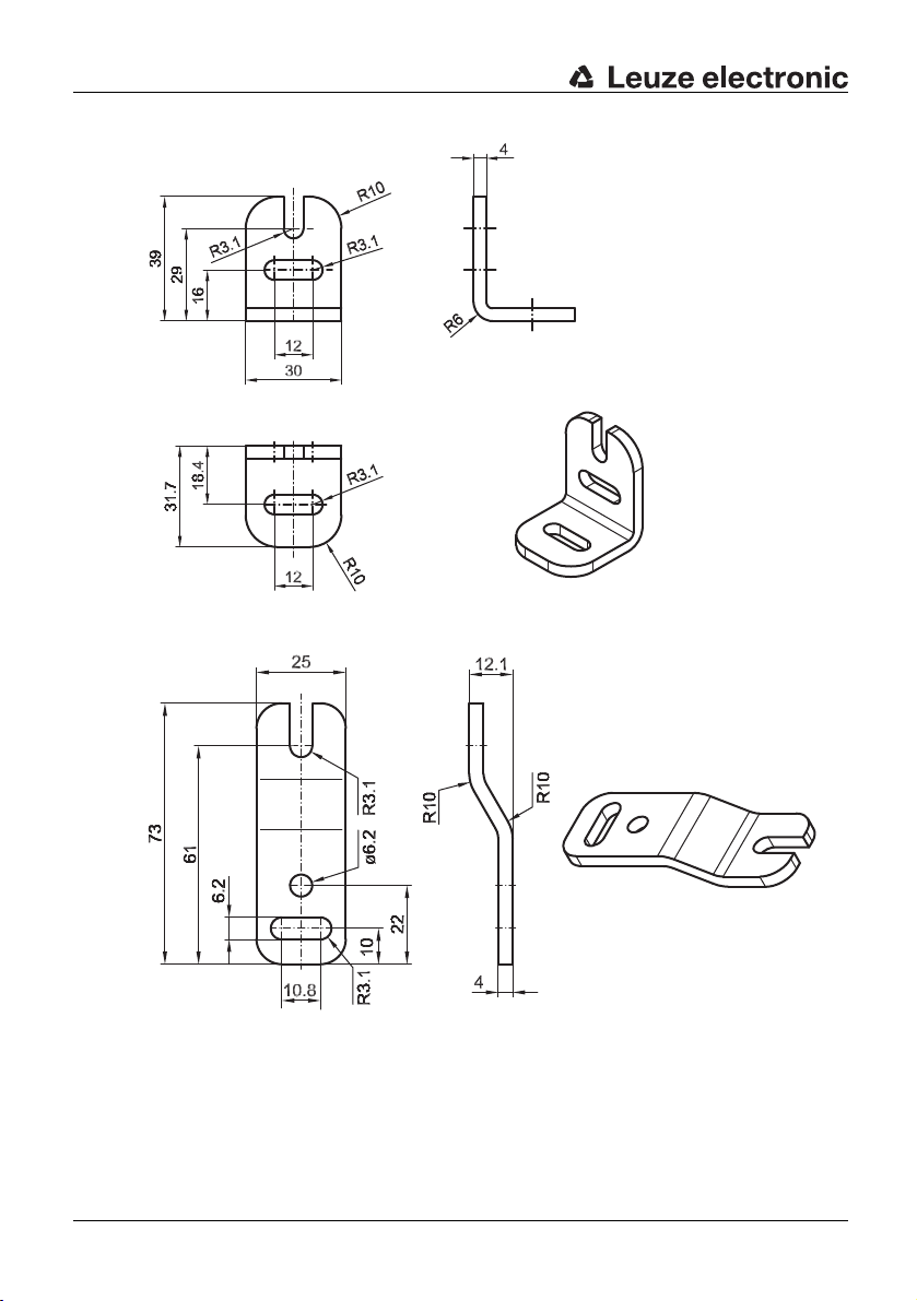
Technical data
DEUTSCH ENGLISH FRANÇAIS ITALIANO ESPAÑOL NEDERLANDS
Fig. 11.5-3: Option: L-mounting bracket
Fig. 11.5-4: Op
62 SOLID-4 Leuze electronic
tion: Z-mounting bracket
Page 63

12 Appendix
12.1 SOLID-4 scope of delivery
SOLID-4 Safety Light Curtains are delivered with:
• 1 SD4T Transmitter unit
• 1 SD4R Receiver unit
• 4 brackets, 360° rotation
• 1 connecting and operating instructions manual
Also delivered for the series SD4 14, SD4 20, SD4 30 and SD4 40:
• 1 test rod AC-TB14/30 (SD4 14/30), AC-TB20 (SD4 20) or AC-TB40 (SD4 40)
12.2 SOLID-4 ordering information
Transmitter SD4T SD4T-14 SD4T-20 SD4T-30 SD4T-40 SD4T-90
SD4Txx-150 67843501 67841701 67841801 67841901
SD4Txx-225 67841702 67841802 67841902
SD4Txx-300 67843503 67841703 67841803 67841903
SD4Txx-450 67843504 67841704 67841804 67841904
SD4Txx-600 67843506 67841706 67841806 67841906 67842006
SD4Txx-750 67843507 67841707 67841807 67841907 67842007
SD4Txx-900 67843509 67841709 67841809 67841909 67842009
SD4Txx-1050 67843510 67841710 67841810 67841910 67842010
SD4Txx-1200 67843512 67841712 67841812 67841912 67842012
SD4Txx-1350 67843513 67841713 67841813 67841913 67842013
SD4Txx-1500 67843515 67841715 67841815 67841915 67842015
SD4Txx-1650 67843516 67841716 67841816 67841916 67842016
SD4Txx-1800 67843518 67841718 67841818 67841918
Receiver SD4R-E SD4R-14 SD4R-20 SD4R-30 SD4R-40 SD4R-90
SD4Rxx-150E 67843401 67840401 67840801 67841201
SD4Rxx-225E 67840402 67840802 67841202
SD4Rxx-300E 67843403 67840403 67840803 67841203
SD4Rxx-450E 67843404 67840404 67840804 67841204
SD4Rxx-600E 67843406 67840406 67840806 67841206 67841606
SD4Rxx-750E 67843407 67840407 67840807 67841207 67841607
SD4Rxx-900E 67843409 67840409 67840809 67841209 67841609
SD4Rxx-1050E 67843410 67840410 67840810 67841210 67841610
SD4Rxx-1200E 67843412 67840412 67840812 67841212 67841612
SD4Rxx-1350E 67843413 67840413 67840813 67841213 67841613
SD4Rxx-1500E 67843415 67840415 67840815 67841215 67841615
SD4Rxx-1650E 67843416 67840416 67840816 67841216 67841616
SD4Rxx-1800E 67843418 67840418 67840818 67841218 67841618
Appendix
DEUTSCHENGLISHFRANÇAISITALIANOESPAÑOLNEDERLANDS
67842018
TNT 35/7-24V
Leuze electronic SOLID-4 63
Page 64

Appendix
DEUTSCH ENGLISH FRANÇAIS ITALIANO ESPAÑOL NEDERLANDS
Receiver SD4R SD4R-14 SD4R-20 SD4R-30 SD4R-40 SD4R-90
SD4Rxx-150 67843201 67840201 67840601 67841001
SD4Rxx-225 67840202 67840602 67841002
SD4Rxx-300 67843203 67840203 67840603 67841003
SD4Rxx-450 67843204 67840204 67840604 67841004
SD4Rxx-600 67843206 67840206 67840606 67841006 67841406
SD4Rxx-750 67843207 67840207 67840607 67841007 67841407
SD4Rxx-900 67843209 67840209 67840609 67841009 67841409
SD4Rxx-1050 67843210 67840210 67840610 67841010 67841410
SD4Rxx-1200 67843212 67840212 67840612 67841012 67841412
SD4Rxx-1350 67843213 67840213 67840613 67841013 67841413
SD4Rxx-1500 67843215 67840215 67840615 67841015 67841415
SD4Rxx-1650 67843216 67840216 67840616 67841016 67841416
SD4Rxx-1800 67843218 67840218 67840618 67841018 67841418
64 SOLID-4 Leuze electronic
Page 65

12.2.1 SOLID-4E Host ordering information
Transmitter SD4T-H SD4T-14 SD4T-20 SD4T-30 SD4T-40 SD4T-90
SD4Txx-300H 67845003 67845103 67845203 67845303 67845403
SD4Txx-450H 67845004 67845104 67845204 67845304 67845404
SD4Txx-600H 67845006 67845106 67845206 67845306 67845406
SD4Txx-750H 67845007 67845107 67845207 67845307 67845407
SD4Txx-900H 67845009 67845109 67845209 67845309 67845409
SD4Txx-1050H 67845010 67845110 67845210 67845310 67845410
SD4Txx-1200H 67845012 67845112 67845212 67845312 67845412
SD4Txx-1350H 67845013 67845113 67845213 67845313 67845413
SD4Txx-1500H 67845015 67845115 67845215 67845315 67845415
SD4Txx-1650H 67845016 67845116 67845216 67845316 67845416
SD4Txx-1800H 67845018 67845118 67845218 67845318
Receiver SD4R-EH SD4R-14 SD4R-20 SD4R-30 SD4R-40 SD4R-H-90
SD4Rxx-300EH 67844103 67844303 67844503 67844703 67844903
SD4Rxx-450EH 67844104 67844304 67844504 67844704 67844904
SD4Rxx-600EH 67844106 67844306 67844506 67844706 67844906
SD4Rxx-750EH 67844107 67844307 67844507 67844707 67844907
SD4Rxx-900EH 67844109 67844309 67844509 67844709 67844909
SD4Rxx-1050EH 67844110 67844310 67844510 67844710 67844910
SD4Rxx-1200EH 67844112 67844312 67844512 67844712 67844912
SD4Rxx-1350EH 67844113 67844313 67844513 67844713 67844913
SD4Rxx-1500EH 67844115 67844315 67844515 67844715 67844915
SD4Rxx-1650EH 67844116 67844316 67844516 67844716 67844916
SD4Rxx-1800EH 67844118 67844318 67844518 67844718 67844918
Appendix
DEUTSCHENGLISHFRANÇAISITALIANOESPAÑOLNEDERLANDS
67845418
TNT 35/7-24V
Leuze electronic SOLID-4 65
Page 66

Appendix
12.2.2 SOLID-4 Guest ordering information
DEUTSCH ENGLISH FRANÇAIS ITALIANO ESPAÑOL NEDERLANDS
Transmitter SD4T-14 SD4T-20 SD4T-30 SD4T-40 SD4T-90
SD4Txx-150G 67847001 67847101 67847201 67847301 67847401
SD4Txx-225G 67847102 67847202 67847302 67847402
SD4Txx-300G 67847003 67847103 67847203 67847303 67847403
SD4Txx-450G 67847004 67847104 67847204 67847304 67847404
SD4Txx-600G 67847006 67847106 67847206 67847306 67847406
SD4Txx-750G 67847007 67847107 67847207 67847307 67847407
SD4Txx-900G 67847009 67847109 67847209 67847309 67847409
SD4Txx-1050G 67847010 67847110 67847210 67847310 67847410
SD4Txx-1200G 67847012 67847112 67847212 67847312 67847412
SD4Txx-1350G 67847013 67847113 67847213 67847313 67847413
SD4Txx-1500G 67847015 67847115 67847215 67847315 67847415
SD4Txx-1650G 67847016 67847116 67847216 67847316 67847416
SD4Txx-1800G 67847018 67847118 67847218 67847318
Receiver SD4R-14 SD4R-20 SD4R-30 SD4R-40 SD4R-90
SD4Rxx-150G 67846001 67846201 67846401 67846601 67846801
SD4Rxx-225G 67846202 67846402 67846602 67846802
SD4Rxx-300G 67846003 67846203 67846403 67846603 67846803
SD4Rxx-450G 67846004 67846204 67846404 67846604 67846804
SD4Rxx-600G 67846006 67846206 67846406 67846606 67846806
SD4Rxx-750G 67846007 67846207 67846407 67846607 67846807
SD4Rxx-900G 67846009 67846209 67846409 67846609 67846809
SD4Rxx-1050G 67846010 67846210 67846410 67846610 67846810
SD4Rxx-1200G 67846012 67846212 67846412 67846612 67846812
SD4Rxx-1350G 67846013 67846213 67846413 67846613 67846813
SD4Rxx-1500G 67846015 67846215 67846415 67846615 67846815
SD4Rxx-1650G 67846016 67846216 67846416 67846616 67846816
SD4Rxx-1800G 67846018 67846218 67846418 67846618 67846818
67847418
Device variants with fixed-connected L and U-shape on request.
66 SOLID-4 Leuze electronic
Page 67

12.3 SOLID-4 accessories ordering information
Article
no.
429050 BT-360° Bracket, 360° rotation
429055 BT-360°-SET Mounting bracket set, consisting of 2 BT-360°
429051 BT-L L-mounting bracket
429052 BT-Z Z-mounting bracket
429056 BT-L-mounting set Consisting of 2 L-type mounting brackets
429057 BT-Z-mounting set Consisting of 2 Z-mounting brackets
560300 BT-SSD Mounting bracket, swiveling with shock
Connecting cable, 5-pin for transmitter
429071 CB-M12-5000S-5GF Connecting cable shielded with M12 coupling,
429072 CB-M12-5000S-5WF Connecting cable shielded with M12 coupling,
429073 CB-M12-10000S-5GF Connecting cable shielded with M12 coupling,
429074 CB-M12-10000S-5WF Connecting cable shielded with M12 coupling, angled,
429075 CB
429076 CB
429171 CB
429172 CB-M12-25000S-5WF Connecting cable, shielded with M12 coupling, 5-pin,
Connecting cable, 8-wire for SD4R-E Receiver
429081 CB-M12-5000S-8GF Connecting cable shielded with M12 coupling, straight,
429082 CB
429083 CB
429084 CB
429085 CB
429086 CB
429181 CB
429182 CB-M12-25000S-8WF Connecting cable, shielded with M12 coupling, 8-pin,
Article Description
incl. 2 screws and 2 sliding nuts
straight, 5 m long
angled, 5 m long
straight, 10 m long
10 m
long
-M12-15000S-5GF Connecting cable shielded with M12 coupling, straight,
-M12-15000S-5WF Connecting cable shielded with M12 coupling, angled,
-M12-25000S-5GF Connecting cable, shielded with M12 coupling, 5-pin,
-M12-5000S-8WF Connecting cable shielded with M12 coupling, angled,
-M12-10000S-8GF Connecting cable shielded with M12 coupling, straight,
-M12-10000S-8WF Connecting cable shielded with M12 coupling, angled,
-M12-15000S-8GF Connecting cable shielded with M12 coupling, straight,
-M12-15000S-8WF Connecting cable shielded with M12 coupling, angled,
-M12-25000S-8GF Connecting cable, shielded with M12 coupling, 8-pin,
15 m long
15 m long
25 m
, straight/open end
25 m,
angled/open end
5 m long
5 m long
10 m long
10 m long
15 m long
15 m long
25 m
, straight/open end
25 m,
angled/open end
Appendix
DEUTSCHENGLISHFRANÇAISITALIANOESPAÑOLNEDERLANDS
absorber
TNT 35/7-24V
Leuze electronic SOLID-4 67
Page 68

Appendix
DEUTSCH ENGLISH FRANÇAIS ITALIANO ESPAÑOL NEDERLANDS
Article
no.
Host terminating plug
426122 AC-H-END Terminating plug set for SOLID-4E Host, Transmitter
Protective Screens
346803 PS-SD-300 Protective Screen, 300 mm, 341.5 mm long
346804 PS-SD-450 Protective Screen, 450 mm, 491.5 mm long
346806 PS-SD-600 Protective Screen, 600 mm, 641.5 mm long
346807 PS-SD-750 Protective Screen, 750 mm, 791.5 mm long
346809 PS-SD-900 Protective Screen, 900 mm, 941.5 mm long
346810 PS-SD-1050 Protective Screen, 1,050 mm, 1,091.5 mm long
346812 PS-SD-1200 Protective Screen, 1,200 mm, 1,241.5 mm long
346813 PS-SD-1350 Protective Screen, 1,350 mm, 1,391.5 mm long
346815 PS-SD-1500 Protective Screen, 1,500 mm, 1,541.5 mm long
346816 PS-SD-1650 Protective Screen, 1,650 mm, 1,691.5 mm long
346818 PS-SD-1800 Protective Screen, 1,800 mm, 1,841.5 mm long
429042 AC-PS-MB-SD-1 Set Mounting bracket consisting of two brackets, suitable
429043 AC-PS-MB-SD-2 Set Mounting bracket consisting of th
Power Supplies
520060 SITOPpower Power supply, 120/230 V AC
520061 LOGO! power Power supply, 120/230 V AC
Test Rods
349945 AC-TB14/30 Test Rod, 14 mm/30 mm
349557 AC-TB40 Test Rod, 40 mm
Safety Relays
549918 MSI-RM2 Relay module, two-channel, for AOPDs with 2 OSSDs
549986 MSI-SR4
Article Description
eiver
and Rec
r lengths 300 mm - 1,050 mm
o
f
for lengths 1,200 mm - 1,800 mm
→ 24 V DC/5 A, regulated
→ 24 V DC/1.3 A, regulated
and E
DM
E-STOP switching device, cat. 4
ree brackets, suitable
68 SOLID-4 Leuze electronic
Page 69
Appendix
Article
no.
Safety Interfaces
549900 MSI-s/R Type 4 safety interface, relay output
549901 MSI-sx/Rx Type 4 safety interface, extended, relay-output
549902 MSI-i/R Type 4 safety interface, cycle control, relayoutput
549903 MSI-ix/Rx Type 4 safety interface, cycle control, extended, relay
549904 MSI-m/R Type 4 safety interface, muting, relay-output
549980 MSI-mE/R Type 4 safety interface, muting, relay output, UL/CSA,
549905 MSI-mx/Rx Type 4 safety interface, muting, extended, relay output
549982 MSI-mxE/Rx Type 4 safety interface, muting, extended, relay output,
549906 MSI-mi/R Type 4 safety interface, muting and cycle control, relay
549907 MSI-mix/Rx
Article Description
12.4 Checklists
The inspection before first startup determines the safety-related flawless integration of the
active opto-electronic protective device (AOPD) into the machine and its control system.
The results of the inspection must be recorded in writing and kept with the machine
documents. They can then be used as a reference during subsequent regular inspections.
out
pu
t
ext.
temperature range, 60 °C
UL
/CSA,
ext. temperature range, 60 °C
out
t
pu
Type 4 safety interface, muting and cycle control,
extended, relay output
DEUTSCHENGLISHFRANÇAISITALIANOESPAÑOLNEDERLANDS
Leuze electronic SOLID-4 69
TNT 35/7-24V
Page 70

Appendix
12.4.1 Checklist for point of operation guarding
DEUTSCH ENGLISH FRANÇAIS ITALIANO ESPAÑOL NEDERLANDS
For a SOLID-4 Safety Light Curtain (resolution 14 mm to 40 mm), with normal approach to
the protective field.
This checklist is intended as a help tool. It supports but does not replace the inspection
before first startup or the respective regular inspections by an expert.
• Is the safety distance calculated in accordance with the valid formulas for
poin
t of operation guarding, while taking the effective resolution and the
response time of the AOPD, the response time of a possibly used safety
interface and the stopping time of the machine into consideration, and has
this minimum distance between the protective field and the point of
operation been observed?
• Is access to the point of operation only possible through the protective field
of
he AOPD and are other possible accesses protected by suitable safety
t
components?
• Is the protective field effective at each side and positively tested according
to
• Is reaching-over, reaching-under or r
effectively prevented, e.g. by mechanical measures (welded or screwed)?
• Is unprotected presence between the protecti
safely excluded, e.g. with fixed physical measures or with the control of
monitored physical components?
• Are transmitter and receiver fixed against displacement/turning after the
al
• Are the protective device and the control devices in good, fault-free
conditi
• Are all connectors and connecting cables in fault-free conditions? Yes No
• Is the start/restart button for resetting the AOPD positioned outside the
danger zone i
• Are the safety switching outputs (OSSDs), linked into the downstream
machine control
• Are the downstream circuit elements controlled by the AOPD monitored by
the
safety valves?
• Does the actual integration of the AOPD into the machine control unit match
t
• Is the AOPD effective during the entire dangerous movement of the
machine?
• Is the dangerous movement stopped immediately if the supply voltage of the
AO
machine again after the supply voltage returns?
er 9.3?
Chapt
eaching-around the protective field
ve field and point of operation
ent?
ignm
on?
n line with specifications and is it effective?
unit in accordance with the required safety category?
feedback circuit (EDM), e.g. contactors with positive-guided contacts or
he circuit
diagrams?
PD is interrupted and is the start/restart button required to start the
Yes No
Yes No
Yes No
Yes No
Yes No
Yes No
Yes No
Yes No
Yes No
Yes No
Yes No
Yes No
Yes No
70 SOLID-4 Leuze electronic
Page 71

12.4.2 Checklist for danger zone guarding
For a SOLID-4 Safety Light Curtain with parallel approach to the protective field
This checklist is intended as a help tool. It supports but does not replace the inspection
before first startup or the respective regular inspections by an expert.
• The minimum height of the protective field above the reference plane relates
to
the resolution of the AOPD. Was the resolution used when calculating the
minimum height and is this height ensured?
• Is the safety distance calculated in acc
for danger zone guarding and is this minimum distance between the most
distant effective beam and the point of operation observed?
• During risk assessment, has it been ensured that only protective field
height
s
less than 300 mm above the floor are regarded as low enough not to
be crawled under (EN 999)?
• Is the access to the point of operation only possible through the protective
f
i
eld of the AOPD and are other access possibilities, especially from the
sides, protected by suitable hard guards or other means?
• Is unprotected presence between the next beam and the point of operation
def
i
nitively excluded?
• Are transmitter and receiver fixed against displacement/turning after the
alignment?
Are the protective device and the control devices in good, fault-free
•
• Are all connectors and connecting cables in fault-free conditions? Yes No
• Is the start/restart button for starting/restarting the AOPD positioned outside
• Are the safety outputs (OSSDs) linked into the downstream machine control
• Are the downstream circuit elements controlled by the AOPD monitored by
• Does the actual integration of the AOPD into the machine control unit match
• Is the AOPD effective during the entire dangerous movement of the
•
on?
conditi
th
e danger zone and is it effective?
in accordance with the required safety category?
unit
e feedback circuit (EDM), e.g. contactors with positive-guided contacts or
th
safety valves?
t
h
e circuit diagrams?
machine?
Does the dangerous movement stop immediately if the supply voltage of the
PD is interrupted and is the start/restart button required to reset the
AO
machine again after the supply voltage returns?
ordance wit
h the applicable formulas
Appendix
DEUTSCHENGLISHFRANÇAISITALIANOESPAÑOLNEDERLANDS
Yes No
Yes No
Yes No
Yes No
Yes No
Yes No
Yes No
Yes No
Yes No
Yes No
TNT 35/7-24V
Yes No
Yes No
Yes No
Leuze electronic SOLID-4 71
Page 72
Appendix
12.4.3 Checklist for access guarding
DEUTSCH ENGLISH FRANÇAIS ITALIANO ESPAÑOL NEDERLANDS
For a SOLID-4 Safety Light Curtain with normal approach to the protective field
This checklist is intended as a help tool. It supports but does not replace the inspection
before first startup or the respective regular inspections by an expert.
• Has the safety distance been calculated in accordance with the applicable
regulations
point of operation been observed?
• Are the required beam heights of the lowest and the highest beam complied
wi
th
• If access to the point of operation is possible through routes other than the
protec
by other means?
• Are the protective device and the control devices in good, fault-free
condit
• Are transmitter and receiver fixed against displacement/turning after the
alignm
• Are all connectors and connecting cables in fault-free conditions? Yes No
• Is the start/restart button for resetting the AOPD positioned outside of the
danger zone in line wit
inside? Is there a complete overview of the danger zone from the start/
restart button position?
• Are both safety-related switching outputs (OSSDs) linked into the downstream machine control unit in accordance with the required safety category?
• Are the subsequent switching elements controlled by the AOPD, e.g.
cont
feedback circuit (EDM)?
• Does the actual integration of the AOPD into the machine control unit match
t
he circuit
• Does the AOPD respond correctly when any beam is interrupted and does
the st
absolutely necessary, as the access, not the presence in the danger zone is
recorded.
• Does the dangerous movement stop immediately if the supply voltage of the
A
O
electronic protective device again after the supply voltage returns?
, and has this minimum distance between protective field and the
(see Chapter 6.1.3)?
tive field of the AOPD, are the other access options suitably secured
i
on?
ent?
h
specifications so that it cannot be reached from
ors with positive-guided contacts or safety valves monitored via the
act
diagrams?
art/restart interlock lock when the beam is interrupted? This is
PD is interrupted and is the start/restart button required to reset the opto-
Yes No
Yes No
Yes No
Yes No
Yes No
Yes No
Yes No
Yes No
Yes No
Yes No
Yes No
72 SOLID-4 Leuze electronic
Page 73

12.5 EC Declaration of Conformity
Appendix
DEUTSCHENGLISHFRANÇAISITALIANOESPAÑOLNEDERLANDS
You can download this EC Declaration of Conformity from the Internet under:
http://www.leuze.com/sol
Leuze electronic SOLID-4 73
id
TNT 35/7-24V
 Loading...