

Leuze electronic SOLID-2, SD2R20, SD2T20, SD2T30, SD2R30 Connecting And Operating Instructions
...Page 1

SOLID-2
Safety Light Curtain
607374 - 2015/04
Subject to change wit-
hout prior notice
CONNECTING AND OPERATING INSTRUCTIONS
Original Instructions
Page 2

Notes on Connecting and Operating Instructions
DEUTSCH ENGLISH FRANÇAIS ITALIANO ESPAÑOL NEDERLANDS
This connecting and operating instructions manual contains information on the proper use
of SOLID-2 Safety Light Curtains in accordance with its intended purpose.
All the information contained herein, in particular the safety notes, need to be carefully
observed.
Notes regarding safety and warnings are marked by this symbol .
Notes regarding important pieces of information are marked by the symbol .
This connecting and operating instructions manual must be stored carefully. It must be
available for the entire operating time of the SOLID-2.
The Leuze electronic GmbH + Co. KG is not liable for damages caused by improper use.
Acquaintance with these instructions is an element of the knowledge required for proper
use.
© Reprints and reproduction, in whole or in part, are permitted only with the explicit
permission of
Leuze electronic GmbH + Co. KG
In der Braike 1
D-73277 Owen - Teck / Germany
Telefon +49 (0) 7021 / 573-0
Fax +49 (0) 7021 / 573-199
info@leuze.de
www.leuze.com
2 SOLID-2 Leuze electronic
Page 3

Contents
1 General . . . . . . . . . . . . . . . . . . . . . . . . . . . . . . . . . . . . . . . . . . . . . . . . . . . . . . . . . . . . . . . . . . . . . 5
1.1 Certifications . . . . . . . . . . . . . . . . . . . . . . . . . . . . . . . . . . . . . . . . . . . . . . . . . . . . . . . . . . . . 5
1.2 Symbols and terms . . . . . . . . . . . . . . . . . . . . . . . . . . . . . . . . . . . . . . . . . . . . . . . . . . . . . . . 6
1.3 Selecting a SOLID-2 . . . . . . . . . . . . . . . . . . . . . . . . . . . . . . . . . . . . . . . . . . . . . . . . . . . . . . 8
1.3.1 SOLID-2 Safety Light Curtains . . . . . . . . . . . . . . . . . . . . . . . . . . . . . . . . . . . . . . . . 8
2Safety . . . . . . . . . . . . . . . . . . . . . . . . . . . . . . . . . . . . . . . . . . . . . . . . . . . . . . . . . . . . . . . . . . . . . . 9
2.1 Approved purpose and foreseeable improper operation . . . . . . . . . . . . . . . . . . . . . . . . . 9
2.1.1 Proper use . . . . . . . . . . . . . . . . . . . . . . . . . . . . . . . . . . . . . . . . . . . . . . . . . . . . . . . . 9
2.1.2 Foreseeable misuse . . . . . . . . . . . . . . . . . . . . . . . . . . . . . . . . . . . . . . . . . . . . . . . 10
2.2 Competent personnel . . . . . . . . . . . . . . . . . . . . . . . . . . . . . . . . . . . . . . . . . . . . . . . . . . . . 11
2.3 Responsibility for safety . . . . . . . . . . . . . . . . . . . . . . . . . . . . . . . . . . . . . . . . . . . . . . . . . . 11
2.4 Exemption of liability . . . . . . . . . . . . . . . . . . . . . . . . . . . . . . . . . . . . . . . . . . . . . . . . . . . . . 11
2.5 Additional safety instructions for access guarding with SOLID-2 . . . . . . . . . . . . . . . . . . 11
3 System design and selectable functions . . . . . . . . . . . . . . . . . . . . . . . . . . . . . . . . . . . . . . . . 13
3.1 The opto-electronic protective device . . . . . . . . . . . . . . . . . . . . . . . . . . . . . . . . . . . . . . . 13
3.2 Functions of the Transmitter . . . . . . . . . . . . . . . . . . . . . . . . . . . . . . . . . . . . . . . . . . . . . . . 13
3.2.1 Transmission channel . . . . . . . . . . . . . . . . . . . . . . . . . . . . . . . . . . . . . . . . . . . . . . 13
3.2.2 Internal or external testing . . . . . . . . . . . . . . . . . . . . . . . . . . . . . . . . . . . . . . . . . . 14
3.3 Selectable function of the Receiver Standard and Extended . . . . . . . . . . . . . . . . . . . . . 14
3.3.1 Transmission channel . . . . . . . . . . . . . . . . . . . . . . . . . . . . . . . . . . . . . . . . . . . . . . 14
3.4 Additional functions of the Receiver Extended . . . . . . . . . . . . . . . . . . . . . . . . . . . . . . . . 15
3.4.1 Start/restart interlock (RES) . . . . . . . . . . . . . . . . . . . . . . . . . . . . . . . . . . . . . . . . . . 15
3.4.2 Contactor monitoring (EDM) . . . . . . . . . . . . . . . . . . . . . . . . . . . . . . . . . . . . . . . . . . . . . . 16
4 Display elements . . . . . . . . . . . . . . . . . . . . . . . . . . . . . . . . . . . . . . . . . . . . . . . . . . . . . . . . . . . . 17
4.1 Transmitter status displays . . . . . . . . . . . . . . . . . . . . . . . . . . . . . . . . . . . . . . . . . . . . . . . . 17
4.2 Receiver status displays . . . . . . . . . . . . . . . . . . . . . . . . . . . . . . . . . . . . . . . . . . . . . . . . . . 18
4.2.1 7-segment display . . . . . . . . . . . . . . . . . . . . . . . . . . . . . . . . . . . . . . . . . . . . . . . . 18
4.2.2 LED displays . . . . . . . . . . . . . . . . . . . . . . . . . . . . . . . . . . . . . . . . . . . . . . . . . . . . . 19
DEUTSCHENGLISHFRANÇAISITALIANOESPAÑOLNEDERLANDS
5 Installation . . . . . . . . . . . . . . . . . . . . . . . . . . . . . . . . . . . . . . . . . . . . . . . . . . . . . . . . . . . . . . . . . 21
5.1 Calculating minimum distances . . . . . . . . . . . . . . . . . . . . . . . . . . . . . . . . . . . . . . . . . . . . 21
5.1.1 Safety distance for safeguarding danger points . . . . . . . . . . . . . . . . . . . . . . . . . 21
5.1.2 Safety distance for safeguarding danger areas . . . . . . . . . . . . . . . . . . . . . . . . . . 23
5.1.3 Safety distance and beam heights for access guarding . . . . . . . . . . . . . . . . . . . . . . . . 25
5.1.4 Minimum distance from reflective surfaces . . . . . . . . . . . . . . . . . . . . . . . . . . . . . . . . . . 27
5.2 Mounting notes . . . . . . . . . . . . . . . . . . . . . . . . . . . . . . . . . . . . . . . . . . . . . . . . . . . . . . . . . 28
5.3 Mechanical mounting . . . . . . . . . . . . . . . . . . . . . . . . . . . . . . . . . . . . . . . . . . . . . . . . . . . . 29
5.4 Mounting types . . . . . . . . . . . . . . . . . . . . . . . . . . . . . . . . . . . . . . . . . . . . . . . . . . . . . . . . . 29
5.4.1 Standard mounting . . . . . . . . . . . . . . . . . . . . . . . . . . . . . . . . . . . . . . . . . . . . . . . . 29
5.4.2 Option: Mounting with swiveling brackets . . . . . . . . . . . . . . . . . . . . . . . . . . . . . . . . . . . 30
5.4.3 Option: Side mounting . . . . . . . . . . . . . . . . . . . . . . . . . . . . . . . . . . . . . . . . . . . . . 30
6 Electrical connection . . . . . . . . . . . . . . . . . . . . . . . . . . . . . . . . . . . . . . . . . . . . . . . . . . . . . . . . 31
6.1 M12 connection . . . . . . . . . . . . . . . . . . . . . . . . . . . . . . . . . . . . . . . . . . . . . . . . . . . . . . . . 31
6.1.1 Transmitter . . . . . . . . . . . . . . . . . . . . . . . . . . . . . . . . . . . . . . . . . . . . . . . . . . . . . . 31
6.1.2 Receiver Standard . . . . . . . . . . . . . . . . . . . . . . . . . . . . . . . . . . . . . . . . . . . . . . . . 33
6.1.3 Receiver Extended . . . . . . . . . . . . . . . . . . . . . . . . . . . . . . . . . . . . . . . . . . . . . . . . . . . . . 35
Leuze electronic SOLID-2 3
TNT 35/7-24V
Page 4

7 Commissioning . . . . . . . . . . . . . . . . . . . . . . . . . . . . . . . . . . . . . . . . . . . . . . . . . . . . . . . . . . . . . 37
DEUTSCH ENGLISH FRANÇAIS ITALIANO ESPAÑOL NEDERLANDS
7.1 Startup . . . . . . . . . . . . . . . . . . . . . . . . . . . . . . . . . . . . . . . . . . . . . . . . . . . . . . . . . . . . . . . . 37
7.1.1 Transmitter display . . . . . . . . . . . . . . . . . . . . . . . . . . . . . . . . . . . . . . . . . . . . . . . . 37
7.1.2 Receiver display . . . . . . . . . . . . . . . . . . . . . . . . . . . . . . . . . . . . . . . . . . . . . . . . . . 37
7.2 Aligning transmitter and receiver . . . . . . . . . . . . . . . . . . . . . . . . . . . . . . . . . . . . . . . . . . . 39
7.2.1 Optimized aligning with the aid of the Receiver’s 7-segment display . . . . . . . . . 39
8 Testing . . . . . . . . . . . . . . . . . . . . . . . . . . . . . . . . . . . . . . . . . . . . . . . . . . . . . . . . . . . . . . . . . . . . 40
8.1 Testing before setting the protective device in service the first time . . . . . . . . . . . . . . . . 40
8.2 Regular tests . . . . . . . . . . . . . . . . . . . . . . . . . . . . . . . . . . . . . . . . . . . . . . . . . . . . . . . . . . . 40
8.3 Daily testing with the test rod . . . . . . . . . . . . . . . . . . . . . . . . . . . . . . . . . . . . . . . . . . . . . . 40
8.4 Cleaning the front screens . . . . . . . . . . . . . . . . . . . . . . . . . . . . . . . . . . . . . . . . . . . . . . . . 41
9 Troubleshooting . . . . . . . . . . . . . . . . . . . . . . . . . . . . . . . . . . . . . . . . . . . . . . . . . . . . . . . . . . . . 42
9.1 What should I do if an error occurs? . . . . . . . . . . . . . . . . . . . . . . . . . . . . . . . . . . . . . . . . . 42
9.2 Diagnostics . . . . . . . . . . . . . . . . . . . . . . . . . . . . . . . . . . . . . . . . . . . . . . . . . . . . . . . . . . . . 42
9.2.1 Transmitter diagnostics . . . . . . . . . . . . . . . . . . . . . . . . . . . . . . . . . . . . . . . . . . . . . 42
9.2.2 Receiver diagnostics . . . . . . . . . . . . . . . . . . . . . . . . . . . . . . . . . . . . . . . . . . . . . . . 42
9.3 AutoReset . . . . . . . . . . . . . . . . . . . . . . . . . . . . . . . . . . . . . . . . . . . . . . . . . . . . . . . . . . . . . 43
10 Technical data . . . . . . . . . . . . . . . . . . . . . . . . . . . . . . . . . . . . . . . . . . . . . . . . . . . . . . . . . . . . . . 44
10.1 General data . . . . . . . . . . . . . . . . . . . . . . . . . . . . . . . . . . . . . . . . . . . . . . . . . . . . . . . . . . . 44
10.1.1 Protective field data . . . . . . . . . . . . . . . . . . . . . . . . . . . . . . . . . . . . . . . . . . . . . . . . 44
10.1.2 Safety relevant technical data . . . . . . . . . . . . . . . . . . . . . . . . . . . . . . . . . . . . . . . . 44
10.1.3 General system data . . . . . . . . . . . . . . . . . . . . . . . . . . . . . . . . . . . . . . . . . . . . . . . . . . . . 45
10.1.4 Transmitter signal inputs . . . . . . . . . . . . . . . . . . . . . . . . . . . . . . . . . . . . . . . . . . . . 45
10.1.5 Receiver Extended signal inputs . . . . . . . . . . . . . . . . . . . . . . . . . . . . . . . . . . . . . . 46
10.1.6 Receiver transistor safety switch outputs . . . . . . . . . . . . . . . . . . . . . . . . . . . . . . . . . . . . 47
10.2 Dimensions, weights and response times . . . . . . . . . . . . . . . . . . . . . . . . . . . . . . . . . . . . 48
10.2.1 Safety Light Curtains . . . . . . . . . . . . . . . . . . . . . . . . . . . . . . . . . . . . . . . . . . . . . . . 48
10.2.2 Dimensions of mounting brackets . . . . . . . . . . . . . . . . . . . . . . . . . . . . . . . . . . . . . 49
11 Appendix . . . . . . . . . . . . . . . . . . . . . . . . . . . . . . . . . . . . . . . . . . . . . . . . . . . . . . . . . . . . . . . . . . 52
11.1 SOLID-2 scope of delivery . . . . . . . . . . . . . . . . . . . . . . . . . . . . . . . . . . . . . . . . . . . . . . . . 52
11.2 Order numbers . . . . . . . . . . . . . . . . . . . . . . . . . . . . . . . . . . . . . . . . . . . . . . . . . . . . . . . . . 52
11.3 Accessories . . . . . . . . . . . . . . . . . . . . . . . . . . . . . . . . . . . . . . . . . . . . . . . . . . . . . . . . . . . . 53
11.4 Checklists . . . . . . . . . . . . . . . . . . . . . . . . . . . . . . . . . . . . . . . . . . . . . . . . . . . . . . . . . . . . . 54
11.4.1 Checklist for safeguarding danger points . . . . . . . . . . . . . . . . . . . . . . . . . . . . . . . . . . . . 55
11.4.2 Checklist for safeguarding danger areas . . . . . . . . . . . . . . . . . . . . . . . . . . . . . . . . . . . . 56
11.4.3 Checklist for access guarding . . . . . . . . . . . . . . . . . . . . . . . . . . . . . . . . . . . . . . . . . . . . . 57
4 SOLID-2 Leuze electronic
Page 5

1 General
SOLID-2 Safety Light Curtains are type 2 Active Opto-electronic Protective Devices,
(AOPDs) in accordance with EN/IEC 61496-1, EN/IEC 61496-2, PL c in accordance with
ISO 13849-1, designed to Safety Integrated Level 1 (SIL 1) as per EN IEC 61508.
All SOLID-2 Safety Light Curtains are equipped with integrated cyclical testing and
display elements (LEDs and 7-segment display).
placing a unit in service or performing diagnostics.
The SOLID-2 is equipped with 2 OSSDs (transistor outputs) with M12 connectors as
standard features.
In addition to the features of the Standard version, the Extended version also offers a
selectable start/restart interlock and contactor monitoring feature.
To provide the best possible solutions for specific applications, SOLID-2 series devices
are available in various resolutions and protective field heights.
1.1 Certifications
Company
Leuze electronic GmbH & Co. KG in D-73277 Owen - Teck, Germany, has a certified
quality assurance system in compliance with ISO 9001.
General
This is especially convenient when
DEUTSCHENGLISHFRANÇAISITALIANOESPAÑOLNEDERLANDS
Products
SOLID-2 Safety Light Curtains are developed and manufactured in compliance with
applicable European directives and international standards.
EC prototype testing in accordance with
EN IEC 61496 Part 1 and Part 2
TÜV PRODUCT SERVICE GmbH, IQSE
Ridlerstrasse 65
D-80339 Munich
Leuze electronic SOLID-2 5
TNT 35/7-24V
Page 6

General
1.2 Symbols and terms
DEUTSCH ENGLISH FRANÇAIS ITALIANO ESPAÑOL NEDERLANDS
Symbols used:
Warning notice. This symbol indicates possible dangers.
Please pay especially close attention to these instructions!
Table 1.2-1: Symbols
A note, which also refers to a course of action, provides information
about special attributes or describes set-up procedures
Notice on important information
Symbols of the Transmitter SD2T
General transmitter symbol
Transmitter not active
Transmitter active
Symbols for Receiver SD2R
General receiver symbol
The receiver’s active protective field is not free. Outputs in OFF state
The receiver’s active protective field is free. Outputs in ON state
The receiver’s active protective field is free. Outputs in OFF state
Signal output
Signal input
Signal input and/or output
6 SOLID-2 Leuze electronic
Page 7

General
Terms used in this manual:
AOPD Active Opto-electronic Protective Device
AutoReset After an error indication, for example because of a faulty
Contactor monitoring
(EDM)
OSSD1, OSSD2 Safety-related switch output
RES Start/REStart interlock
Response time of AOPD The time lag between penetration into the active protective field
Scan All beams, beginning with the synchronization beam, are
Start/restart interlock
(RES)
TC1 Transmission channel 1
TC2 Transmission channel 2
Table 1.2-2: Terms
external wiring, the AOPD attempts to start again. If the
error is no longer present, the AOPD returns to normal state.
Also called External Device Monitoring (EDM), monitors
dynamically the positive-guided normally closed contacts of
downstream relays, contactors or valves
Output Signal Switching Device
of the AOPD and the actual switching off of the OSSDs
pulsed by the transmitter in cycles one after the other
Prevents automatic start after the supply voltage has been
turned on, or after the protective field has been penetrated
DEUTSCHENGLISHFRANÇAISITALIANOESPAÑOLNEDERLANDS
Leuze electronic SOLID-2 7
TNT 35/7-24V
Page 8

General
SD2trr-xxxx v*
SOLID-2
t - Type of device
T: Transmitter
R: Receiver
r - Resolution
20: 20 mm
30: 30 mm
40: 40 mm
90: 90 mm
xxxx- Protective field height
150 ..... 1800 mm (for 20, 30 and 40 mm resolution)
600..... 3000 mm (for 90 mm resolution)
v- Function version
E: Extended version (with selectable start/restart
interlock and contactor monitoring)
Standard version (automatic start/restart without
contactor monitoring)
*) In the Standard version this place in the product
designation is not used
1.3 Selecting a SOLID-2
DEUTSCH ENGLISH FRANÇAIS ITALIANO ESPAÑOL NEDERLANDS
1.3.1 SOLID-2 Safety Light Curtains
Fig. 1.3-1: Selecting a SOLID-2 Safety Light Curtain
8 SOLID-2 Leuze electronic
Page 9

2Safety
Before using the safety sensor, a risk evaluation must be performed according to valid
standards (e.g. EN
result of the risk assessment determines the required safety level of the safety sensor (see
Table 2.1-1). For mounting, operating and testing, document "SOLID-2 Safety Light
Curtain" as well as all applicable national and international standards, regulations, rules
and directives must be observed. Relevant and supplied documents must be observed,
printed out and handed to the affected personnel.
Before working with the safety sensor, completely read and understand the documents
applicable to your task.
In particular, the following national and international legal regulations apply for the startup, technical inspections and work with safety sensors:
• Machinery directive 2006/42/EC
• Low voltage directive 2006/95/EC
• Electromagnetic compatibility directive 2004/108/EC
• Use of Work Equipment Directive 89/655/EEC supplemented by Directive 95/63 EC
• OSHA 1910 Subpart 0
• Safety regulations
• Accident-prevention regulations and safety rules
• Ordinance on Industrial Safety and Health and Labor Protection Act
• Device Safety Act
Notice!
For safety-related information you may also contact the local authorities (e.g., industrial
inspectorate, employer's liability insurance association, labor inspectorate, occupational
safety and health authority).
Safety
ISO 14121, EN ISO 12100-1, ISO 13849-1, IEC 61508, EN 62061). The
DEUTSCHENGLISHFRANÇAISITALIANOESPAÑOLNEDERLANDS
2.1 Approved purpose and foreseeable improper operation
Warning!
A running machine can cause severe injuries!
Make certain that, during all conversions, maintenance work and inspections, the system is
securely shut down and protected against being restarted again.
2.1.1 Proper use
The safety sensor must only be used after it has been selected in accordance with the
respectively applicable instructions and relevant standards, rules and regulations regard
ing labor protection and occupational safety, and after it has been installed on the
machine, connected, commissioned, and checked by a competent person.
When selecting the safety sensor it must be ensured that its safety-related capability
meets or exceeds the required performance level PL
Leuze electronic SOLID-2 9
ascertained in the risk assessment.
r
TNT 35/7-24V
-
Page 10

Safety
DEUTSCH ENGLISH FRANÇAIS ITALIANO ESPAÑOL NEDERLANDS
The following table shows the safety-related characteristic parameters of the SOLID-2
Safety Light Curtain.
Type in accordance with IEC/EN 61496 Type 2
SIL in accordance with IEC 61508 SIL 1
SILCL in accordance with IEC/EN 62061 SILCL 1
Performance Level (PL) in accordance with ISO 13849-1: 2008 PL c
Category in accordance with ISO 13849 Cat. 2
Average probability of a failure to danger per hour (PFHd)
For protective field heights up to 900 mm, all resolutions
For protective field heights up to 1800 mm, all resolutions
For protective field heights up to 2850 mm, all resolutions
Service life (TM) 20 years
8.2 x 10⁻⁸ 1/
8.9 x 10⁻⁸ 1/
On request
h
h
Table 2.1-1: Safety-related characteristic parameters of the SOLID-2 Safety Light
• The safety sensor protects persons at access points or at points of operation of
machines and plants.
• The safety sensor with vertical mounting detects the penetration by fingers and hands
at points of operation or by the body at access points.
• The safety sensor only detects persons upon entry to the danger zone; it does not
detect persons who are located within the danger zone. For this reason, a start/restart
interlock is mandatory.
• The safety sensor with horizontal mounting detects persons who are located within the
danger zone (presence detection).
• The construction of the safety sensor must not be altered. When manipulating the safety
sensor, the protective function is no longer guaranteed. Manipulating the safety sensor
also voids all warranty claims against the manufacturer of the safety sensor.
• The safety sensor must be tested regularly by competent personnel.
• The safety sensor must be exchanged after a maximum of 20 years. Repairs or the
exchange of parts subject to wear and tear do not extend the service life.
Curtain
2.1.2 Foreseeable misuse
In principle, the safety sensor is not suitable as a protective device in case of:
• danger of objects being expelled or hot or dangerous liquids spurting from the danger
zone
• applications in explosive or easily flammable atmospheres
10 SOLID-2 Leuze electronic
Page 11

2.2 Competent personnel
Prerequisites for competent personnel:
• he has a suitable technical education
• he knows the rules and regulations for occupational safety, safety at work and safety
technology and can assess the safety of the machine
• he knows the instructions for the safety sensor and the machine
• he has been instructed by the responsible person on the mounting and operation of the
machine and of the safety sensor
2.3 Responsibility for safety
Manufacturer and operating company must ensure that the machine and implemented
safety sensor function properly and that all affected persons are adequately informed and
trained.
The type and content of all imparted information must not lead to unsafe actions by users.
The manufacturer of the machine is responsible for:
• safe machine construction
• safe implementation of the safety sensor
• imparting all relevant information to the operating company
• adhering to all regulations and directives for the safe starting-up of the machine
The company operating the machine is responsible for:
• instructing the operating personnel
• maintaining the safe operation of the machine
• adhering to all regulations and directives for occupational safety and safety at work
• regular testing by competent personnel
Safety
DEUTSCHENGLISHFRANÇAISITALIANOESPAÑOLNEDERLANDS
2.4 Exemption of liability
Leuze electronic GmbH + Co. KG is not liable in the following cases:
• safety sensor is not used as intended
• safety notices are not adhered to
• reasonably foreseeable misuse is not taken into account
• mounting and electrical connection are not properly performed
• Proper function is not tested (see Chapter 8)
• changes (e.g., constructional) are made to the safety sensor
2.5 Additional safety instructions for access guarding with SOLID-2
Warning!
SOLID-2 Safety Light Curtains with a resolution of 20, 30 or 40 mm detect hands, arms or
bodies of a person entering the protective field, and therefore, it can be placed closer to the
danger point or points than Safety Light Curtains with a resolution of 90 mm. In this case,
Leuze electronic SOLID-2 11
TNT 35/7-24V
Page 12

Safety
DEUTSCH ENGLISH FRANÇAIS ITALIANO ESPAÑOL NEDERLANDS
the height of the highest and lowest beam above the reference plane must be selected in
accordance with EN ISO 13857.
Valid for all design types: In case of access guarding applications, the start/restart
interlock function is obligatory due to the fact that only access to the danger zone, but not
the area between the protective field and the danger points is monitored.
The start/restart button for unlocking the device must be mounted in such a way that it
cannot be reached from inside the danger zone and the entire danger zone is fully visible
form its installation position.
12 SOLID-2 Leuze electronic
Page 13

System design and selectable functions
a
b
3 System design and selectable functions
3.1 The opto-electronic protective device
Working principle
SOLID-2 consists of a transmitter and a receiver. Beginning with the first beam (the
synchronizing beam) directly after the display panel, the transmitter pulses beam for
beam in rapid sequence. The synchronization between transmitter and receiver is
performed optically.
Fig. 3.1-1: Working principle of the opto-electronic protective device
The receiver recognizes the specially coded pulse packages of the transmitter beams
and opens the corresponding receiver elements in sequence in the same rhythm. A
protective field is consequently formed in the area between transmitter and receiver.
Its height depends on the geometrical dimensions of the protective device and its width is
determined by the distance selected between the transmitter and receiver within the
permissible detection range.
Functions such as start/restart interlock or contactor monitoring can optionally be
performed by the Receiver Extended version.
3.2 Functions of the Transmitter
3.2.1 Transmission channel
The infrared beams are modulated with specially coded pulse packages so that the are
distinct from ambient light, thus ensuring undisturbed operation.
Welding sparks or warning flash lights from passing forklifts do not having any effect on
the protective field.
If two protective fields are located directly next to each other for two adjacent machines,
however, measures must be taken to ensure the optical protective devices do not affect
each other.
Both transmitters should first be assembled “back to back“ so that the beams radiate in
opposite directions. This prevents one system from affecting the other.
a=Transmitter
b=Receiver
DEUTSCHENGLISHFRANÇAISITALIANOESPAÑOLNEDERLANDS
TNT 35/7-24V
Leuze electronic SOLID-2 13
Page 14

System design and selectable functions
a
b
Another possible way to suppress mutual influence is to switch one of the two protective
DEUTSCH ENGLISH FRANÇAIS ITALIANO ESPAÑOL NEDERLANDS
3.2.2 Internal or external testing
devices from transmission channel 1 to 2 and thus to differently formed pulse packages.
This solution should be considered when more than two optical safety systems must be
arranged
a=AOPD “A“ transmission channel 1
b=AOPD “B“ transmission channel 2, not affected by AOPD “A“
Fig. 3.2-1: Transmission channel selection
Both the transmitter and the receiver of the optical protective system in question must be
switched from transmission channel 1 to 2. For additional information, see Chapter 6.
If external testing is desired, the test input of the transmitter must be wired in accordance
with the connection and operating instructions of the selected testing safety interface. The
testing safety interface will turn the transmitter off and back on, verifying that the selected
single OSSD of the receiver is turned off and on in accordance. For more details, see
Chapter
In most cases, however, internal cyclical testing is sufficient. For this purpose, the
transmitter‘s test input must be connected with +24V DC. Both OSSDs must be integrated
into the safety circuit as a two-channel system.
next to each other.
6.1.1.2.
3.3 Selectable function of the Receiver Standard and Extended
3.3.1 Transmission channel
If the transmitter is switched to transmission channel 2, the corresponding receiver must
also be set to transmission channel 2
14 SOLID-2 Leuze electronic
. See Chapter 6.
Page 15

System design and selectable functions
3.4 Additional functions of the Receiver Extended
3.4.1 Start/restart interlock (RES)
If the start/restart interlock function is activated, it prevents the safety circuits from being
released automatically when the machine is turned on or the power supply is switched on
or is restored after a power outage. The receiver only switches to the ON state by pressing
and releasing the start/resart button within a time window.
DEUTSCHENGLISHFRANÇAISITALIANOESPAÑOLNEDERLANDS
Fig. 3.4-1: Start/restart interlock function in effect when the supply voltage is turned
If the protective field is interrupted, the start/restart interlock function ensures that the
receiver will remain in the OFF
rece
iver will then not be switched back to the ON state until the start/restart button is
pressed and released again.
Fig. 3.4-2: The start/restart interlock function after the protective field has been
Activate the start/restart interlock:
✟ with the circuitry in the Receiver Extended (see Chapter 6.1.3)
✟ or in the downstream machine control unit
✟ or in the downstream safety PLC
Once the internal start/restart interlock is activated as described in Chapter 6.1.3, this
function is monitored dynamically. The receiver cannot be switched back to the ON state
until the start/restart button is pressed and released again within a time window of 300
to 5
s, with the protective field free.
on
state after the protective field is released again. The
penetrated
ms
TNT 35/7-24V
Leuze electronic SOLID-2 15
Page 16

System design and selectable functions
3.4.2 Contactor monitoring (EDM)
DEUTSCH ENGLISH FRANÇAIS ITALIANO ESPAÑOL NEDERLANDS
If the “Contactor monitoring” function is activated, it dynamically monitors contactors,
relays or valves downstream from the SOLID-2. Precondition here are switching elements
with positive-guided feedback contacts (normally closed).
Fig. 3.4-3: Contact monitoring function, combined in this example with a start/
You can implement the contactor monitoring function with:
✟ The internal contactor monitoring in the Receiver Extended (see Chapter 6.1.3)
✟ or via a downstream safety PLC
If the internal contactor monitoring function is activated, it works dynamically, i.e. in
addition to verifying that the feedback loop is closed before turning on the OSSDs the
system checks whether the feedback circuit has opened within 500 ms of being enabled
and whether it has closed again within 500 ms when turning off the
the case, the OSSDs will assume an OFF state again shortly after turning on.
message appears at the 7-segment display, E 30.
restart interlock
OSSDs. If this is not
A error
16 SOLID-2 Leuze electronic
Page 17

4 Display elements
ab
4.1 Transmitter status displays
When the transmitter’s green LED1 is lit, this indicates that the supply voltage is available.
Fig. 4.1-1: Transmitter, LED status displays
Display of the current state of the transmitter:
Indication Meaning
LED1 green LED2 off Supply voltage present, TC1 selected
LED1 green LED2 green Supply voltage present, TC2 selected
LED1 green LED2 red Supply voltage present, TC1 or TC2 selected, external
LED1 red LED2 any state Device fault
Table 4.1-1: Transmitter, LED status displays
a = LED1 (green/red)
b = LED2 (green/red)
test signal activated
Display elements
DEUTSCHENGLISHFRANÇAISITALIANOESPAÑOLNEDERLANDS
TNT 35/7-24V
Leuze electronic SOLID-2 17
Page 18

Display elements
bd
c
a
4.2 Receiver status displays
DEUTSCH ENGLISH FRANÇAIS ITALIANO ESPAÑOL NEDERLANDS
4.2.1 7-segment display
LED1 and the 7-segment display report on the operating states of the Receiver Standard.
LED2 is added in case of Receiver Extended.
Fig. 4.2-1: Receiver, status displays
After the electrical supply voltage is turned on, the following data appear on the receiver’s
7- segment display:
7-segment
display
1 or 2 Indication of transmission channel TC1 or TC2
a=Symbol for OSSDs
b=LED1 = red/green
c=Symbol for interlocking state
d=LED2 = yellow
Meaning
Permanent display after startup
Table 4.2-1: Receiver, 7-segment permanent displays
7-segment
Meaning
display
Temporary event displays, 1 s per display
E xx Locking status display “error“, which can be eliminated by the user
E xx = Error code (for example contactor monitoring error E 30, see Chapter 9). The display shows repeating the sequence of E, 3 (1st position)
and 0 (2nd position).
F xx Locking status display „device fault“ and an internal fault code.
Receiver must be replaced.
1 or 2
flashing
Table 4.2-2: Receiver, 7-segment temporary event display
Flashing transmission channel number → weak signal display, device not
adjusted optimally or contaminated front screens
18 SOLID-2 Leuze electronic
Page 19

4.2.2 LED displays
4.2.2.1 Receiver Standard, LED status displays
LED Color Meaning
LED1 red/
green
Table 4.2-3: Receiver Standard, LED status displays
red = OSSDs safety outputs in the OFF state
green = OSSDs safety outputs in the ON state
No display = Device without supply voltage
4.2.2.2 Receiver Extended, LED status displays
If the internal start/restart function is not activated, the Receiver Extended indicates only
the status of the OSSDs safety outputs in the same way like the Receiver Standard,
described under
The following table is valid, if the internal start/restart function is activated.
LED Color Meaning
LED1 red/
LED2 yellow ON = Internal start/restart interlock activated; The OSSDs
green
4.2.2.1.
red = OSSDs safety outputs in the OFF state
green = OSSDs safety outputs in the ON state
No display = No supply voltage to the device
safety outputs are switched to the OFF state. If the
protective field is free,
the device can be unlocked by pressing and
releasing the start/restart button in a time window of
300 ms to 5 s.
OFF = If the OSSDs are in ON state (LED1 green):
Internal start/restart interlock function is not activated.
If OSSDs are in OFF state (LED1 red):
Internal start/restart function is activated and the
protective field is not free.
Display elements
DEUTSCHENGLISHFRANÇAISITALIANOESPAÑOLNEDERLANDS
TNT 35/7-24V
Table 4.2-4: Receiver Extended, LED status displays when start/restart interlock
Leuze electronic SOLID-2 19
function is activated
Page 20

Display elements
4.2.2.3 Receiver Extended, LED displays and protective field states when the internal
DEUTSCH ENGLISH FRANÇAIS ITALIANO ESPAÑOL NEDERLANDS
start/restart interlock function is activated:
LED1 LED2 Protective
field
green OFF free LED1
red OFF interrupted LED1 red = OSSDs safety outputs in the OFF state
red yellow free LED1 red = OSSDs safety outputs in the OFF state
Table 4.2-5: Receiver Extended with selected internal start/restart interlock function
The following illustrations show the behaviour of the LEDs and OSSDs in start/restart
interlock operating mode.
a b c d e
Meaning
green
LED2 OFF = Start/restart interlock not active, see Fig.
LED2 OFF = Start/restart interlock not active.
LED2
yellow
= OSSDs safety outputs in the ON state
4.2-2 a
As long as the protective field is interrupted, it is not possible to start/restart the device, see Fig. 4.2-2 b
= Start/restart interlock active. The OSSDs
safety outputs are only turned on again af
ter pressing and releasing the start/restart
button in a time window of 300 ms to 5 s,
see Fig. 4.2-2 c-e
-
LED1: green
LED2: OFF
OSSDs: ON
Fig. 4.2-2: Start/restart interlock function after intrusion into the protective field
20 SOLID-2 Leuze electronic
LED1: red
LED2: OFF
OSSDs: OFF
LED1: red
LED2: yellow
OSSDs: OFF
LED1: green
LED2: OFF
OSSDs: ON
Page 21

5 Installation
This section contains important information on installing the SOLID-2. The effects of its
effective protection are only guaranteed if the following installation requirements are
observed. These installation specifications are based on the respective applicable
versions of European standards such as EN 999 and EN
countries outside of the EU, the valid requirements in those countries must also be
observed. The installation depends greatly on the type of protection being provided.
Because of this, the situations of:
• Safeguarding danger points
• Safeguarding danger areas
• Access guarding
are considered separately below. The applicable distance from the protective device to
reflective surfaces in the surrounding area are presented for all types of protection based
on these situations.
5.1 Calculating minimum distances
Light curtains can only perform their protective function if they are mounted with a
sufficient safety distance. The calculation formulas for the safety distance depend on the
type of protection. In the harmonized European standard EN 999, “Positioning of
protective devices with regard to approach speed of parts of the human body“, the
installation situations and calculation formulas for safety distance are described for the
types of protection named above.
The formulas for the required distances to reflective surfaces are based on the European
standard for “Active opto-electronic protective devices“ prEN IEC 61496-2.
Installation
ISO 13857. If SOLID-2 is used in
DEUTSCHENGLISHFRANÇAISITALIANOESPAÑOLNEDERLANDS
5.1.1 Safety distance for safeguarding danger points
Calculation of the safety distance for a SOLID-2 Safety Light Curtain with resolution of 20,
30 or 40 mm to safeguard danger points:
The safety distance S for safeguarding danger points is derived in accordance with EN
999 from the formula:
S [mm] = K [mm/s] x T [s] + C [mm]
Leuze electronic SOLID-2 21
TNT 35/7-24V
Page 22

Installation
b
c
d
f
e
a
DEUTSCH ENGLISH FRANÇAIS ITALIANO ESPAÑOL NEDERLANDS
S = Safety distance in mm
If the result is less than 100 mm, a distance of at least 100 mm must still be
maintained.
K = Approach speed in mm/s
In the close range of 500 mm, 2000 mm/s is used for the calculation. If the distance greater than 500 mm is calculated, K = 1600 mm/s may be used.
However, in this case a minimum safety distance of 500 mm is applied.
T = Total time of the delay in seconds;
Total of:
the response time of the protective device t
the response time of the safety interface, if any t
and the machine‘s stopping time t
Machine
a)
AOPD
c)
Interface
b)
C = 8 x (d-14) in mm
Additional amount depending on depth of penetration into the protective field
before switching of the AOPD
d = Resolution of the AOPD
a)
see Chapter 10.2
b)
see specifications of the safety interface
c)
Specifications of the machine or stopping time measurement
a = Safety distance (S)
b = Measures to prevent penetration from above
c = Measures to prevent penetration from the sides
d = Measures to prevent penetration from the rear
e = Measures to prevent penetration from below
f = 75 mm – Maximum distance to avoid walking
behind*
Fig. 5.1-1: Safety distance (a) for safeguarding danger points
*) If because of the safety distance this value cannot be achieved, other measures e.g.mechanical
barriers must provide this distance.
S [mm] = 2000 [mm/s] x (t
AOPD
+ t
Interface
+ t
) [s] + 8 x (d-14) [mm]
Machine
22 SOLID-2 Leuze electronic
Page 23

Calculation example for safeguarding danger points:
c
b
d
a
A light curtain with a resolution of 20 mm, protective field height 1500 mm is used on a
machine with a stopping time of 150 ms. The response time of the safety interface is
20
ms.
Stopping time of the machine t
Response time t
Response time t
AOPD
= 20 ms
Interface
= 150 ms
Machine
= 49 ms
Resolution d of the AOPD = 20 mm
T = 0.150 s + 0.049 s + 0.020 s = 0.219 s
S = 2000 x 0.219 + 8 x (20 -14) = 486 mm
Make certain during assembly that it is not possible to reach over, around or under or to
walk behind the
protective device.
5.1.2 Safety distance for safeguarding danger areas
Calculation of the safety distance and required resolution for a Safety Light Curtain to
secure danger areas.
Installation
DEUTSCHENGLISHFRANÇAISITALIANOESPAÑOLNEDERLANDS
a = Safety distance (S)
b = Measures to prevent access from the sides
c = Height above the reference plane
d = max. distance < 75 mm*
Fig. 5.1-2: Safety distance (a) and height (c) for safeguarding danger areas
*) If this value can not be achieved because of the safety distance, other measures, e.g. mechanical
barriers, must guarantee for that required maximum distance of 75 mm.
Leuze electronic SOLID-2 23
TNT 35/7-24V
Page 24

Installation
DEUTSCH ENGLISH FRANÇAIS ITALIANO ESPAÑOL NEDERLANDS
The height of the protective field H above the reference plane and the resolution d of the
AOPD are related to each other as follows:
Hmin [mm] = 15 x (d -50) [mm] or d [mm] = H/15 + 50 [mm]
H = Height of the protective field above the reference plane, maximum 1000 mm
Heights equal to or less than 300 mm are considered too low for adults to crawl
under
d = Resolution of the AOPD
The safety distance S for safeguarding danger areas is derived in accordance with EN
999 from the formula:
S [mm] = K [mm/s] x T [s] + C [mm]
S = Safety distance in mm
K = Approach speed of 1600 in mm/s.
T = Total time of the delay in seconds;
Total of:
the response time of the protective device t
the response time of the safety interface, if any t
and the stopping time of the machine t
Machine
AOPD
c)
a)
Interface
b)
C = (1200 mm – 0,4 H), but not less than 850 mm (arm’s length)
H = Height of the protective field above the floor
a)
see Chapter 10.2
b)
see specifications of the safety interface
c)
Specifications of the machine or stopping time measurement
S [mm] = 1600 [mm/s] x (t
AOPD
+ t
Interface
+ t
) [s] + (1200 – 0,4 H) [mm]
Machine
24 SOLID-2 Leuze electronic
Page 25

5.1.3 Safety distance and beam heights for access guarding
a
b
c
d
Determination of the beam heights and calculation of the safety distance of Safety Light
Curtains with a resolution of 20, 30 or 40
limited space between the protective field and a danger point.
mm for use as access guarding, for example with
Installation
DEUTSCHENGLISHFRANÇAISITALIANOESPAÑOLNEDERLANDS
a = Safety distance (protective field/danger
point),
b = Height of the lowest beam above reference
plane, see Table 5.1-1
c = Height of the highest beam, see Table 5.1-1
d = Measures to prevent access from the sides
Fig. 5.1-3: Access guarding with Safety Light Curtain, resolution of 20, 30 or 40 mm
Warning!
Please consider the additional safety instructions for access guarding with SOLID-2 in
Chapter 2.5.
Beam heights with use of Safety Light Curtain to guard access in accordance with
EN 999 and EN ISO 13857:
Design Resolu-
ion
Lowest beam above
reference plane
Highest beam above reference plane
Additional
amount C
(see formula
Chapter 5.1.1)
SD2-20-xxxx 20 mm As per EN ISO 13857 As per EN ISO 13857 48 mm
SD2-30-xxxx 30 mm As per EN ISO 13857 As per EN ISO 13857 128 mm
SD2-40-xxxx 40 mm As per EN ISO 13857 As per EN ISO 13857 208 mm
SD2-90-xxxx 90 mm 300 mm 1200 mm 850 mm
Table 5.1-1: Beam heights above the reference plane and additional amount C for
access guarding applications
Leuze electronic SOLID-2 25
TNT 35/7-24V
Page 26

Installation
DEUTSCH ENGLISH FRANÇAIS ITALIANO ESPAÑOL NEDERLANDS
Calculation formula for safety distance S based on EN 999:
Calculation of the safety distance for a Safety Light Curtain with a resolution of up to
40
mm, used to guard access. The safety distance S is calculated as described by
EN
999 according to the formula:
S [mm] = K [mm/s] x T [s] + C [mm]
S = Safety distance in mm
K = Approach speed in mm/s
In the close area of 500 mm, the speed is calculated at 2000 mm/s. If the distance is greater than 500 mm, K can be calculated as 1600 mm/s. In this case,
however, a minimum of 500 mm applies to the safety distance.
T = Total time of the delay in seconds;
Total of:
the response time of the protective device t
the response time of the safety interface, if any tI
and the stopping time of the machine t
Machine
AOPD
c)
a)
nterface
b)
C = 8 x (d-14) in mm
Additional amount depending on the depth of penetration into the protective
field before turning on the AOPD
d = Resolution of AOPD up to a maximum of
40
mm
a)
see Chapter10.2
b)
see specifications of the safety interface
c)
Specifications of the machine or stopping time measurement
S [mm] = 2000 [mm/s] x (t
AOPD
+ t
Interface
+ t
) [s] + 8 x (d-14) [mm]
Machine
If the resolution is greater than 40 mm for example for SOLID-2 Safety Light Curtains with a
resolution of 90 mm, an additional amount is required:
C = 850 mm (arm’s length)
The safety distance is thus calculated according to the following formula:
S [mm] = 1600 [mm/s] x (t
AOPD
+ t
Interface
+ t
) [s] + 850 [mm]
Machine
Warning!
Please consider the additional safety instructions for access guarding with SOLID-2 in
Chapter 2.5.
26 SOLID-2 Leuze electronic
Page 27

5.1.4 Minimum distance from reflective surfaces
c
b
a
4°± 25%
4°± 25%
130
a
b
Reflective surfaces in the area of opto-electronic protective devices can indirectly deflect
beams from the transmitter into the receiver. This can cause an object in the protective
field not to be detected! All reflective surfaces and objects (for example material
containers, sheets) must be kept at a minimum distance „a“ . The minimum distance
depends on the distance „b“ between the transmitter and the receiver.
a = Minimum distance
b = Reflective surface
c = Protective field width
Fig. 5.1-4: Minimum distances from reflective surfaces
Installation
DEUTSCHENGLISHFRANÇAISITALIANOESPAÑOLNEDERLANDS
a=Required distance from reflective surfaces [mm]
b=Width of protective field [m]
Fig. 5.1-5: Minimum distances from reflective surfaces as a function of the width of
the protective field
Safety light curtains of the SOLID-2 product line are equipped with an optics of less beam
aperture than required by EN IEC 61496-1, -2. Thus, less distances between reflecting
surfaces and protective field are needed than typically required.
Warning!
Replacing with safety light curtains of different production lines fulfilling the minimum
requirements of the above mentioned standards may request higher distances.
Leuze electronic SOLID-2 27
TNT 35/7-24V
Page 28

Installation
5.2 Mounting notes
DEUTSCH ENGLISH FRANÇAIS ITALIANO ESPAÑOL NEDERLANDS
Special notes on mounting a SOLID-2 Safety Light Curtain for safeguarding danger
points (
✟ Calculate the safety distance according to the formula in Chapter 5.1.1.
✟ Ensure that it is impossible to reach under, over, around or walk behind the protective
field.
✟ Observe the maximum distance between machine table and protective field of 75 mm,
with reference to a table height of 750 mm. If this is not possible because the safety
distance is too big, e.g. a mechanical barrier must be provided.
✟ Observe the minimum required distance to reflective surfaces.
Special notes on mounting a SOLID-2 Safety Light Curtain for safeguarding danger areas
(
see Fig. 5.1-2):
✟ Calculate the safety distance according to the formula in Chapter 5.1.2.
✟ The resolution determines the minimum height of the protective field above the floor.
The calculation formula can also be found in Chapter
✟ Ensure that the maximum height of the protective field above the reference plane of
1000 mm is not exceeded and only heights equal to or less than 300 mm are
considered impossible for an adult to crawl under (also see EN 999).
✟ It must not be possible to step into the danger area from the sides. Suitable hard guards
must be provided.
✟ Consider the position of the last light beam before the machine. It must not be possible
to stand undetected between this light beam and the machine.
Special notes on mounting a SOLID-2 Safety Light Curtain for access guarding (see
Fig. 5.1-3):
✟ Calculate the safety distance according to the formula in Chapter 5.1.3.
✟ The highest and the lowest light beam and thus the height of the protective field for
Safety Light Curtains with a resolution of 20, 30 or 40
requirements described in EN
✟ Access guarding systems must only be operated with start/restart interlock. Activate the
start/restart interlock internal or of a downstream safety interface and
sure it is working.
✟ Ensure while installing the start/restart button, that it must only be impossible to press
this button from the inside the danger zone. Make sure, that from the location of the
button there is a complete overview over the danger zone.
see Fig. 5.1-1):
5.1.2.
mm is determined from the
ISO 13857.
check to make
28 SOLID-2 Leuze electronic
Page 29

5.3 Mechanical mounting
What should generally be taken into consideration during installation?
✟ Make certain that the transmitter and receiver are mounted on even surfaces.
✟ The transmitter and receiver must be positioned at the same height and their
connection plugs must be pointing in the same direction.
✟ Use screws for mounting that can only be loosened with a tool.
✟ Fasten and secure the transmitter and receiver so that they cannot be swiveled or
moved. Securing transmitter and receiver so they cannot be moved or swiveled is
especially important in the close area with a narrow protective field.
✟ The safety distance between the protective field and the danger zone must be
observed.
✟ Make certain that access to the danger point/danger area is only possible through the
protective field. Additional access routes must be secured separately (for example by
hard guards, additional safety light curtains or doors with locking devices).
5.4 Mounting types
5.4.1 Standard mounting
Four standard mounting brackets (two each for transmitter and receiver) are included with
delivery.
Installation
DEUTSCHENGLISHFRANÇAISITALIANOESPAÑOLNEDERLANDS
Fig. 5.4-1: Standard mounting bracket examples
Leuze electronic SOLID-2 29
TNT 35/7-24V
Page 30
Installation
L-mounting bracket
Z-mounting bracket
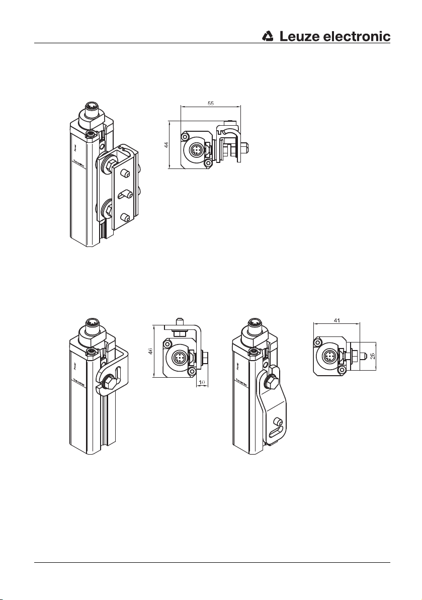
5.4.2 Option: Mounting with swiveling brackets
DEUTSCH ENGLISH FRANÇAIS ITALIANO ESPAÑOL NEDERLANDS
5.4.3 Option: Side mounting
Four swivel mounting brackets with shock absorbers can be ordered optionally. They are
not included with delivery.
Fig. 5.4-2: Swiveling mounting bracket with shock absorber
Optionally, mounting is possible with L- or Z-mounting brackets (with sliding nuts and
screws) using the side groove. They are not included with delivery.
The swivel range is ± 8°.
Fig. 5.4-3: Mounting examples, L-mounting bracket and Z-mounting bracket
30 SOLID-2 Leuze electronic
Page 31

6 Electrical connection
• The electrical connection must be performed by experienced personnel. Knowledge of
all safety instructions in these connecting and operating instructions is part of this
competence.
• The external supply voltage of 24V DC ± 20 % must guarantee safe isolation from mains
voltage and be able to bridge a power outage period of at least 20 ms. Leuze
electronic offers suitable power supplies (see list of accessories in the Appendix).
• The power supply selected must not support any other parts of the machine with power
other than the safety components connected. It must provide at least 1 A. Transmitter
and receiver must be fused against overcurrent.
• It is vital during the electrical installation for the power of the machine or system to be
protected is switched off and locked, so that the dangerous movements cannot be
started unintentionally. Only after the safety function on the protective device is entirely
checked, its connection to the machine is permissible. For more details see
and 11.4.
6.1 M12 connection
Transmitter and Receiver Standard are equipped with M12, 5-pin plugs while the Receiver
Extended providing additional functions is equipped with a M12, 8-pin plug.
6.1.1 Transmitter
Fig. 6.1-1: SD2T 5-pin (view of the pins)
1 = brown
3 = blue
4 = black
5=grey
Electrical connection
DEUTSCHENGLISHFRANÇAISITALIANOESPAÑOLNEDERLANDS
Chapter 8
Pin Color Assignment Inputs/outputs
1 brown Supply voltage +24V DC for TC1 or 0V for TC2
2 white nc.
3 blue Supply voltage 0V for TC1 or +24V DC for TC2
4 black Test in Test input
5 grey/
connector
enclosure
Table 6.1-1: Transmitter, connection assignment
Leuze electronic SOLID-2 31
Shield Functional earth
Connected to +24V DC
→ internal test activated
Connected to 0V or disconnected
→ external test activated
TNT 35/7-24V
Page 32

Electrical connection
+24V DC
b
a
2 K
External test signal
8 - 150 ms
c
OSSD output
6 ms 6 ms
d
+24V DC
+24V DC
The polarity of of the power supply at Pin1 and Pin3 determines the selected optical
DEUTSCH ENGLISH FRANÇAIS ITALIANO ESPAÑOL NEDERLANDS
6.1.1.1 Internal cyclical testing
6.1.1.2 External test signal
transmission channel. If +24V DC is present on Pin1 and 0V on Pin3 transmission
channel
1 is selected. If 0V is present on Pin1 and +24V DC on Pin3 transmission
channel
2 is selected.
Make certain to select the same transmission channel for both, for transmitter and
receiver.
Warning!
For optimal shielding cables must be used, where the shield is led on the knurled nut of the
connecting cable socket (such cables are listed under accessories in Chapter
To activate internal cyclical testing, connect Pin4 of the transmitter to +24V DC.
Warning!
While using the internal cyclical testing both of the OSSDs must by used to open the safety
circuit redundant.
To use the external testing option, connect the test output of the corresponding testing
safety interface with Pin4 of the transmitter. In case of using the external testing procedure
in combination with a testing safety interface, only one of the OSSDs needs to be
connected to the testing safety interface.
Note:
External testing takes precedence over the internal testing.
11.3).
Test input Pin4 Transmitter: +24V DC test = not activated
high impedance or 0V test = activated
32 SOLID-2 Leuze electronic
a = transmitter
b = test input pin4
Fig. 6.1-2: Transmitter, external testing
c = high impedance or 0V
d = high impedance
Page 33

6.1.2 Receiver Standard
Fig. 6.1-3: SD2R 5-pin (view of the pins)
Pin Color Assignment Inputs/outputs
1 brown ⇐ Supply volta-
2 white Output OSSD2, switching semicontactor output
3 blue ⇐ Supply volta-
4 black Output OSSD1, switching semicontactor output
5 grey/
connector
enclosure
Table 6.1-2: Receiver Standard, connection assignment
Warning!
The Receiver Standard does not offer the functions start/restart interlock and EDM. These
functions have to be carried out by the downstream machine control unit if required by the
safety category.
1 = brown
2 = white
3 = blue
4 = black
5=grey
+24V DC for TC1 or 0V for TC2
ge
0V for TC1 or +24V DC for TC2
ge
⇐ Shield Functional earth
Electrical connection
DEUTSCHENGLISHFRANÇAISITALIANOESPAÑOLNEDERLANDS
Note:
For optional shielding cables must be used, where the shield is led on the knurled nut of the
connecting cable socket (such cables are listed under assessories in Chapter 11.3).
The polarity of of the power supply at Pin1 and Pin3 determines the selected optical
transmission channel. If +24V DC is present on Pin1 and 0V on Pin3 transmission channel
1 is selected. If 0V is present on Pin1 and +24V DC on Pin3 transmission channel 2 is
selected.
Note:
Make certain to select the same transmission channel for both, for receiver and transmitter.
Leuze electronic SOLID-2 33
TNT 35/7-24V
Page 34

Electrical connection
SOLID-2 / SD2R
+24V
+24V
Tes t
OSSD1
SOLID-2 / SD2T
OSSD2
0V
FE
FE
0V
Var. B
Var. A
4
142
-A1
1 234
-A2
1 2
3
14
-W1 -W2
5
-W2
SH3
-W1
5
SH3
-K3 -K4-K4
-K3
0V
PE
+24V
PE.
+24V
0V.
n.c.
14 24 42
13 23 41
A1
A2
-K3
121
2
L+ L+
L- L-
-S1
-K3
-K4
+24V
0V
MSI-SR4
A1
-A3
A2
S22 S12 S31 S33 S34 S35
2 AOPD-
1 AOPD+
33
34
A1
A2
-K4
2 AOPD+
IV-0
RES-0
RES-I
1
2
*
*
DEUTSCH ENGLISH FRANÇAIS ITALIANO ESPAÑOL NEDERLANDS
Fig. 6.1-4: Connection example SOLID-2 with MSI-SR4 Safety Relay
34 SOLID-2 Leuze electronic
Page 35

6.1.3 Receiver Extended
Fig. 6.1-5: SD2R 8-pin (view of the pins)
Pin Color Assignment Inputs/outputs
1 white Operating
2 brown Supply voltage +24V DC for TC1 or 0V for TC2
3 green Operating
4 yellow nc
5 grey Output OSSD1, switching semicontactor output
6 pink Output OSSD2, switching semicontactor output
7 blue Supply voltage 0V for TC1 or +24V DC for TC2
8 black/
connector
enclosure
1 = white
2 = brown
3 = green
4 = yellow
5=grey
6=pink
7=blue
8 = black
Input BA1
mode selection
Input BA2
mode selection
Shield Functional earth
Electrical connection
DEUTSCHENGLISHFRANÇAISITALIANOESPAÑOLNEDERLANDS
Table 6.1-3: Receiver Extended, connection assignment
6.1.3.1 Selection of the transmission channel
The polarity of of the power supply at pin2 and pin7 determines the selected optical
transmission channel:
If +24V DC is present on pin2 and 0V on pin7 transmission channel 1 is selected.
If 0V is present on pin2 and +24V DC on pin7 transmission channel 2 is selected.
Note:
Make certain to select the same transmission channel for both, for transmitter and receiver.
For optimal shielding cables must be used, where the shield is led on the knurled nut of
the connecting cable socket (such cables are listed under accessories in Chapter
11.3).
6.1.3.2 Operating mode selection RES and contactor monitoring (EDM)
The Receiver Extended has to be connected via the 8-pin M12 connector. The operating
modes S/R and EDM can be activated in several combinations using the pins BA1 (pin1)
and BA2 (pin3) .
Leuze electronic SOLID-2 35
TNT 35/7-24V
Page 36

Electrical connection
BA1
BA2
+24V DC
GND
BA1 BA2
GND
BA2BA1
+24V DC
k2
k1
BA1 BA2
GND
k1
k2
OSSD2
0V
FE
FE
0V BA1
SOLID-2 E / SD2R E
+24V
Tes t
n.c.
+24V
SOLID-2 E/ SD2T MSI-RM2
n.c.
OSSD1
BA2
Var. B
Var. A
A1
A2
-K3
65
1
2
1
2
3SH
8
-W1
7SH
-W2
-S1
A2
5
14B36Y1
1
B1
4
-A3
11
3
12 22
2
-K4
-K3
A1
A2
-K4
21Y2
-W1
41
5
-W2
7
21
-A2
4
3
24
1
-A1
3
2
-K3 -K4-K4
-K3
0V
PE
+24V.
0V
+24V
PE
0V
L+L+
L- L-
Warning!
DEUTSCH ENGLISH FRANÇAIS ITALIANO ESPAÑOL NEDERLANDS
The adaptation of the operating mode is only be carried out in the switched off state of the
receiver. If the adaptation is made during operation, the new values will not be accepted
until the power supply was switched off.
Without RES Without EDM
BA1
0V Start/restart button
pin1
BA2
+24V DC 0V n.c. Via start/restart
pin3
Connection
Table 6.1-4: Receiver Extended, operating mode selection
6.1.3.3 Connection example
With RES
Without EDM
to BA2
Without RES
With EDM
EDM feedback
loop k1/k2 at
+24V
DC
With RES
With EDM
EDM feedback
loop k1/k2 at BA2
button to 0V
Fig. 6.1-6: Connection example SOLID-2E with MSI-RM2 Safety Relay
36 SOLID-2 Leuze electronic
Page 37

7 Commissioning
Warning!
Before placing the SOLID-2 in operation for the first time on a power-driven production
machine, an experienced and commissioned person with suitable training must check the
entire setup and the integration of the opto-electronic protective device into the machine
control system.
Before connecting the supply voltage for the first time and while the transmitter and
receiver are being aligned, it must be ensured that the outputs of the protective device do
not have any effect on the machine. The switching elements that finally set the dangerous
machine in motion must be safely switched off and secured form restarting.
The same precautionary measures apply after every change in operating mode made to
the protective device, after repairs or during maintenace work.
Only after it has been determined that the optical protective device functions are correct it
can be integrated into the machine’s control circuit!
7.1 Startup
Warning!
Without internal start/restart interlock function and the protective field is free the OSSDs
immediately switch to the ON state!
Make certain that the transmitter and receiver are protected against overcurrent (for fuse
size see Chapter
power supply must have a load current reserve of at least 1 A and the ability to bridge a
power outage for at least 20 ms, and it must guarantee secure mains supply isolation.
10.1.2). There are special requirements for the supply voltage: The
Commissioning
DEUTSCHENGLISHFRANÇAISITALIANOESPAÑOLNEDERLANDS
7.1.1 Transmitter display
After the power supply is turned on and the selftest is completed, the LEDs indicate the
current operating status (see Chapter
Warning!
If the transmitter’s LED1 lights permanently red, the 24V DC supply voltage and the wiring
must be checked. If the error remains after it is turned on again, discontinue the setup
process immediately and send in the malfunctioning transmitter to be checked.
4.1).
7.1.2 Receiver display
After the receiver is turned on or restarted, the number of the selected transmission
channel appears.
Warning!
In the event of an error or fault, the receiver’s 7-segment display reports it with ”E xx“ or ”F
xx“. The error code in Chapter 9 provides information on whether it is an error (E xx) in
external wiring or an internal device fault (F xx). For internal faults, immediately interrupt
the installation and send in the malfunctioning receiver to be checked.
Leuze electronic SOLID-2 37
TNT 35/7-24V
Page 38

Commissioning
bd
c
a
DEUTSCH ENGLISH FRANÇAIS ITALIANO ESPAÑOL NEDERLANDS
However, if errors are found and cleared in the external wiring, the receiver will be
restored to normal operation mode and startup can be continued.
Warning!
The Receiver Standard and the Receiver Extended without selected start/restart interlock
does not show the yellow LED2 lit after turning on and the OSSDs immediately switch to
the ON-state if the protective field is free. In this case, a downstream safety interface must
provide the start/restart interlock function:
LED Without internal RES, transmitter/
receiver aligned and protective field
free
Without internal RES, transmitter/
receiver not aligned or protective field
not free
LED1 green ON = OSSDs in the ON state red ON = OSSDs in the OFF state
LED2 OFF = RES interlock not availab-
le or not activated
OFF = RES interlock not available
or not activated
Table 7.1-1: Receiver Standard or Receiver Extended with start/restart interlock not
activated, LED displays
The LEDs display of the Receiver Extended with activated internal start/restart interlock
function after it is turned on (for activation see Chapter
LED With internal RES, before unlocking
by the start/restart button while the
protective field is free
6.1.3.2):
With internal RES, after unlocking the
start/restart button while the protective
field is free
LED1 red ON = OSSDs in the OFF state green ON = OSSDs in the ON state
LED2 yellow ON = RES locked OFF = RES unlocked
Table 7.1-2: Receiver Extended with start/restart interlock activated, LED displays
a=Symbol for OSSDs
b=LED1 = red/green
c=Symbol for interlocking state
d=LED2 = yellow
Fig. 7.1-1: Receiver Extended, LED display
38 SOLID-2 Leuze electronic
Page 39

Commissioning
7.2 Aligning transmitter and receiver
Transmitter and receiver must be mounted in place at the same height or, if they are used
horizontally, at the same distance from the reference level.
7.2.1 Optimized aligning with the aid of the Receiver’s 7-segment display
The distinction between protecting field is free (channel number is shown continuously)
and the weak signal mode (channel number is flashing) can be used as a convenient
alignment tool.
When the components are already almost aligned it is recommended to improve the
alignment e.g. by turning the receiver. Turn the receiver with slightly loosened brackets
until the 7-segment display starts to blink. Memorize this position. Now turn the receiver in
the opposite direction until the display lights constantly and further, until it is blinking
again. Now turn the receiver back in between the two positions determined. Screw the
receiver firmly into place to prevent turning. Proceed with the transmitter in the same
manner.
DEUTSCHENGLISHFRANÇAISITALIANOESPAÑOLNEDERLANDS
Leuze electronic SOLID-2 39
TNT 35/7-24V
Page 40
Testing
8 Testing
DEUTSCH ENGLISH FRANÇAIS ITALIANO ESPAÑOL NEDERLANDS
8.1 Testing before setting the protective device in service the first time
Testing by an experienced technician before initial startup must ensure that the optical
protective device and any other safety components that might be present have been
selected in accordance with the required specifications, especially the European Machine
and Machine Utilization Directive, and that they provide the necessary protection when
properly operated.
✟ Use the regulations listed above, where required, with the help of the checklists
provided in the Appendix of these instructions, to check that the protective devices are
properly installed, that they are properly wired into the controls and that they work in all
machine operating modes. When selecting the checklist, note the type of protection
(danger point, danger area or access guarding).
✟ The same testing requirements apply if the machine in question has not been operated
for a longer period of time and after major modifications or repairs if this could affect the
safety of the machine.
✟ Observe the specifications regarding the instructing of operation personnel by experi-
enced technicians before work is started. Instruction of personnel is the responsibility of
the machine owner.
Leuze electronic offers a specialist service, which undertakes the required testing and
monitoring tasks in accordance with the European regulations (www.leuze.de). The results
of these tests are documented for the machine owner consistent with ISO
8.2 Regular tests
Regular tests must also be carried out in accordance with local regulations. They are
designed to discover changes (e.g. in machine stopping times) or manipulations to the
machine controls or protective device.
✟ You must have the effectiveness of the protective device checked by an experienced
technician at suitable intervals, but at least once per year.
✟ The applicable checklist in the Appendix may also be used during regular testing.
Leuze electronic also provides a specialist service for regular tests.
9000.
8.3 Daily testing with the test rod
SOLID-2 Safety Light Curtains are subject to a cyclical testing. Nevertheless it is very
important to check the protective field for its effectiveness daily to ensure that the
protection stays effective at every point after an operation mode or tool change.
Warning!
Use the appropriate test rod (Accessory) but never your fingers, hand or arm for checking
the system!
✟ When selecting the test rod’s diameter, use the nameplate of the receiver indicating the
resolution as a guideline.
✟ If for Receiver Extended the internal start/restart interlock function is selected and the
AOPD is released, LED1 lights up green. When the test rod is inserted, LED1 switches
40 SOLID-2 Leuze electronic
Page 41

Testing
a
to red and LED2 stays in the OFF state. During the test procedure, the yellow LED2
must not light up at any point. Only after the test rod is removed out of the protective
field, the LED2 is allowed to turn to yellow.
a = Beginning of test
Fig. 8.3-1: Testing the protective field with the test rod
✟ If the AOPD is being operated without the internal start/restart interlock, it is sufficient to
watch LED1 on the receiver during the testing procedure. When the test rod is inserted
into the protective field, this LED1 must switch from “green” to “red” and must not switch
back to “green” at any point during the test procedure.
DEUTSCHENGLISHFRANÇAISITALIANOESPAÑOLNEDERLANDS
Warning!
If the test does not yield the desired result, the cause could be a protective field height that
is too low or reflections from reflective metals or tools brought into the area. In this case the
installation of the safety light curtain must be checked by a specialist. If the cause cannot
be clearly defined and remedied, the machine or system must not beoperated any more!
8.4 Cleaning the front screens
The front screens on the transmitters and receivers must be cleaned regularly depending
on how dirty they are. A blinking 7-segment display with the protective field is free (LED1
is green) indicates a “weak signal reception”, cleaning is then required.
If cleaning the screens does not improve this, the detection range and alignment must be
checked.
We recommend using a mild cleanser for cleaning the front screens. The screens are
resistant to thinned acids or alkalis and resistant to organic solvents within limits.
Leuze electronic SOLID-2 41
TNT 35/7-24V
Page 42

Troubleshooting
9 Troubleshooting
DEUTSCH ENGLISH FRANÇAIS ITALIANO ESPAÑOL NEDERLANDS
9.1 What should I do if an error occurs?
9.2 Diagnostics
9.2.1 Transmitter diagnostics
The following information is used for rapid troubleshooting in the event of a malfunction.
If the AOPD shows an error on the display, the machine must be stopped immediately and
checked by an experienced technician. If it is found that the error cannot be clearly
defined and remedied, your local Leuze office and or the Leuze electronic hotline can
assist.
Operational malfunctions often have simple causes that you can remedy yourself. The
following tables will help you do this.
Symptom Measure to eliminate error
LED
is not lit
LED1 is lit red
continuously
Table 9.2-1: Transmitter diagnostics
Check + 24 V DC supply voltage
Check connection cable
Replace transmitter if necessary
Check the test input, hardware fault, replace transmitter if necessary
9.2.2 Receiver diagnostics
The receiver distinguishes between error codes (E xx) and fault codes (F xx). Only error
messages (E) provide information about events or states that you can eliminate. If the
receiver shows a fault code (F), it must be replaced. Consequently, only error codes (E)
are shown in the table below:
Code Cause / significance Measure to eliminate error
LEDs and 7-segment displays are not
lit
8 Lights continuously Hardware error Replace receiver
F xx Internal hardware fault Replace receiver
E 00 Source of failure in the ambient area Eliminate the source of the failure
E 01 Short circuit between OSSD1 and
OSSD 2
Table 9.2-2: Receiver diagnostics
42 SOLID-2 Leuze electronic
Check the + 24 V DC supply voltage
Check the connection cable, replace
the receiver if necessary
Eliminate short circuit
Page 43

Troubleshooting
Code Cause / significance Measure to eliminate error
E 06 Short circuit between GND and
OSSD1
E 07 Short circuit between +24V DC and
OSSD1
E 08 Short circuit between GND and
OSSD2
E 09 Short circuit between +24V DC and
OSSD2
E 14 Power supply undervoltage Check power supply/load
E 17 Operating mode setting incorrect or
start/restart button longer than 60
pressed
E 18 Test signal time-limit exceeded Test signal > 150 ms; check external
E 22 Power supply overvoltage Check the power supply
E 30 EDM error Check connection of feed back con-
Table 9.2-2: Receiver diagnostics
Eliminate short circuit
Eliminate short circuit
Eliminate short circuit
Eliminate short circuit
Invalid wiring combination, check the
wiring and/or button
s
test signal
tacts. Switch off power supply for setting back the system.
DEUTSCHENGLISHFRANÇAISITALIANOESPAÑOLNEDERLANDS
9.3 AutoReset
After an error or a fault has been detected and displayed, an automatic restart occurs
within
• about 2 seconds for the transmitter
• about 10 seconds for the receiver
for the device in question. If the error or fault is no longer present at that time, the machine
or system can be started again.
For EDM errors (E 30) no AutoReset occurs. The Receiver Extended turns to a locking
state. Recovering is possible by removing the supply voltage and checking out the
contactors and wiring of the feed back loop. After the error has been eliminated, connect
the supply voltage again.
Leuze electronic SOLID-2 43
TNT 35/7-24V
Page 44
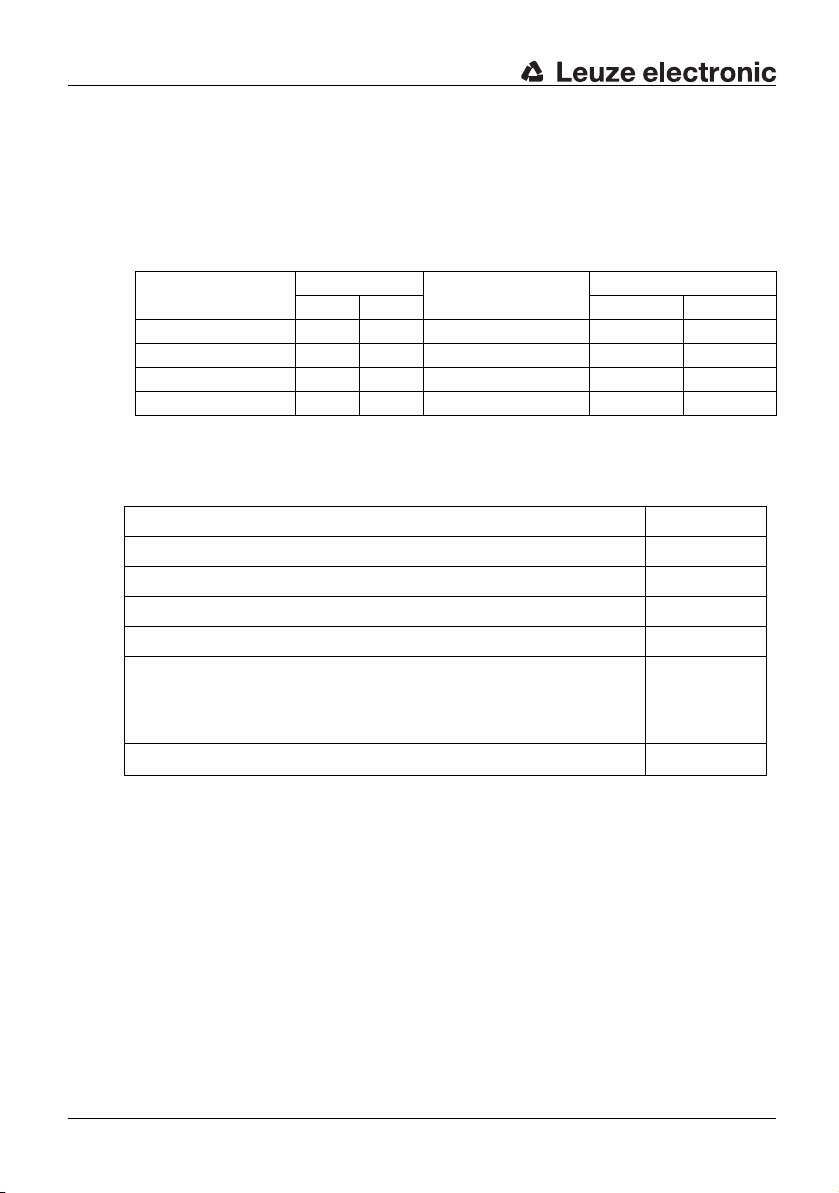
Technical data
10 Technical data
DEUTSCH ENGLISH FRANÇAIS ITALIANO ESPAÑOL NEDERLANDS
10.1 General data
10.1.1 Protective field data
Safety light curtain Range Physical resolution Protective field height
SD2-20 0,5 m 15 m 20 mm 150 mm 1800 mm
SD2-30 0.2 m 10 m 30 mm 150 mm 1800 mm
SD2-40 0.8 m 20 m 40 mm 150 mm 1800 mm
SD2-90 0.8 m 20 m 90 mm 600 mm 1800 mm
Table 10.1-1: Beam and protective field data
10.1.2 Safety relevant technical data
Type in accordance with IEC/EN 61496 Type 2
SIL in accordance with IEC 61508 SIL 1
SILCL in accordance with IEC/EN 62061 SILCL 1
Performance Level (PL) in accordance with ISO 13849-1: 2008 PL c
Category in accordance with ISO 13849 Cat. 2
Average probability of a failure to danger per hour (PFHd)
For protective field heights up to 900 mm, all resolutions
For protective field heights up to 1800 mm, all resolutions
For protective field heights up to 2850 mm, all resolutions
Service life (TM) 20 years
min. max. min. max.
8.2 x 10⁻⁸ 1/
8.9 x 10⁻⁸ 1/
On request
h
h
Table 10.1-2: Safety relevant technical data
44 SOLID-2 Leuze electronic
Page 45

10.1.3 General system data
Technical data
Supply voltage Uv
transmitter and receiver
Residual ripple of supply voltage ± 5 % within the limits of Uv
Power consumption of transmitter 75 mA
Power consumption of receiver 140 mA without external load
Shared value for external fuse in the
supply line for transmitter and receiver
Permissible wire cross-section,
Transmitter/Receiver Standard
Receiver Extended
Transmitter:
Class:
Wave length:
Pulse duration:
Pulse pause:
Output:
Synchronization Optical between transmitter and receiver
Test repetition time for integrated
cyclical test
Safety class (VDE 106)
Type of protection
Ambient temperature, operation 0 ... 50 °C
Ambient temperature, storage -25 ... 70 °C
Relative humidity 15 ... 95 %
Dimensions See dimensional drawings and tables
Weight See table in 10.2.1
*)The circuits connected to the input and outputs must maintain the clearance distances for safe
isolation in the relevant standards
**) Not suited for external operation areas.
+ 24V DC, ± 20 %, external power supply with secure mains supply isolation and equalization for
a 20 ms power outage, minimum 1 A load current
reseve
1A
0,25 mm²
0,14 mm²
Light-emitting diodes as defined by EN 608251:1994+ A1:2002+A2:2001
1
950 nm
7 μs
3,1 ms
< 10 μW
100 ms
III*)
)
IP65**
DEUTSCHENGLISHFRANÇAISITALIANOESPAÑOLNEDERLANDS
TNT 35/7-24V
Table 10.1-3: General system data
10.1.4 Transmitter signal inputs
Test input Input: Contact or semiconductor to +24V DC
Table 10.1-4: Transmitter, Signal input
Leuze electronic SOLID-2 45
Current load: 20 mA max.
Page 46

Technical data
10.1.5 Receiver Extended signal inputs
DEUTSCH ENGLISH FRANÇAIS ITALIANO ESPAÑOL NEDERLANDS
BA1: Signal input: Input: Contact or semiconductor to +24V DC
BA2: Signal input: Input: Contact or semiconductor to +24V DC
Table 10.1-5: Receiver Extended, Signal inputs
or to GND
Current load: 10 mA max.
or to GND
Current load: 10 mA max.
46 SOLID-2 Leuze electronic
Page 47

10.1.6 Receiver transistor safety switch outputs
Technical data
OSSDs
transistor safety switch outputs
2 safety pnp transistor outputs, cross-circuit
monitoring, short-circuit-proof
Minimum Typical Maximum
Switching voltage high active
Switching voltage low
Switching current
Leakage current
Load capacity
Load inductivity
Permissible wire resistance for load – –
Uv - 1,9 V Uv – 1 V
200 mV
< 2 μA*)
Uv - 0,8 V
+ 1 V
250 mA
< 2,2 μF
2,0 H
< 50 Ω**
)
Permissible wire cross-section
Receiver Standard
Receiver Extended
Permissible cable length between
– – 100 m***)
0,25 mm² 0,14
mm²
Receiver and load
Auxiliary pulse width 20 μs – 230 μs
Auxiliary pulse spacing 3,7 ms – 46 ms
OSSD restart after beam interruption
– 100 ms –
w/o RES
OSSD response time Depends on the number of beams. See the tables
in Chapter
*)In the event of an error (if the GND line is interrupted) the output behaves like a 120 kΩ to Uv. A
downstream safety interface/PLC must not detect this as a logical “1“.
**) Note the additional restrictions caused by cable length and load current.
***) The specified cable length may be limited by inductive or capacitive loads.
This limitation can eliminated by terminal resistors (2 kΩ) in parallel to each of the loads,
connected between the OSSDS wire ends and 0V (Ground).
10.2
• Spark suppression is carried out by the transistor outputs. It is therefore not necessary
to use spark extinguishers recommended by manufacturers of contactors and valves
(RC modules, varistors or recovery diodes) with transistor outputs. These would extend
the delay time of the inductive switching elements.
DEUTSCHENGLISHFRANÇAISITALIANOESPAÑOLNEDERLANDS
TNT 35/7-24V
Table 10.1-6: Receiver, Transistor outputs
Leuze electronic SOLID-2 47
Page 48

Technical data
10.2 Dimensions, weights and response times
DEUTSCH ENGLISH FRANÇAIS ITALIANO ESPAÑOL NEDERLANDS
10.2.1 Safety Light Curtains
Type Dimensions [mm] Weight [kg] Response time [ms]
Dim.A Dim.B SD2T/SD2R SD2-20 SD2-30 SD2-40 SD2-90
SD2trr-150 150 225,5 0,3 12 7 7
SD2trr -225 225 300,5 0,4 9 9 9
SD2trr -300 300 375,5 0,4 12 12 12
SD2trr -450 450 525,5 0,6 17 9 9
SD2trr -600 600 675,5 0,7 21 12 12 8
SD2trr -750 750 825,5 0,9 26 14 14 10
SD2trr -900 900 975,5 1,0 31 17 17 12
SD2trr -1050 1050 1125,5 1,2 36 19 19 8
SD2trr -1200 1200 1275,5 1,3 41 21 21 8
SD2trr -1350 1350 1425,5 1,5 46 24 24 9
SD2trr -1500 1500 1575,5 1,6 51 26 26 10
SD2trr -1650 1650 1725,5 1,8 55 29 29 11
SD2trr -1800 1800 1875,5 1,9 60 31 31 12
Table 10.2-1: Safety Light Curtains, dimensions and response times
48 SOLID-2 Leuze electronic
Page 49

A = Protective field height B = Total height without plug
Fig. 10.2-1: Dimensions of Safety Light Curtains
Technical data
DEUTSCHENGLISHFRANÇAISITALIANOESPAÑOLNEDERLANDS
10.2.2 Dimensions of mounting brackets
Fig. 10.2-2: 360° mounting bracket
Leuze electronic SOLID-2 49
TNT 35/7-24V
Page 50

Technical data
DEUTSCH ENGLISH FRANÇAIS ITALIANO ESPAÑOL NEDERLANDS
a = Slot 13 x 6
b = Swiveling angle ±8°
Fig. 10.2-3: Option: Swiveling mounting bracket with shock absorber
50 SOLID-2 Leuze electronic
Page 51

Fig. 10.2-4: Option: L-mounting bracket
Technical data
DEUTSCHENGLISHFRANÇAISITALIANOESPAÑOLNEDERLANDS
Fig. 10.2-5: Option: Z-mounting bracket
Leuze electronic SOLID-2 51
TNT 35/7-24V
Page 52

Appendix
11 Appendix
DEUTSCH ENGLISH FRANÇAIS ITALIANO ESPAÑOL NEDERLANDS
11.1 SOLID-2 scope of delivery
SOLID-2 Safety Light Curtains are delivered with:
1 SD2T transmitter unit
1 SD2R receiver unit
4 360° mounting bracket
1 Connection and Operating Instructions Manual
11.2 Order numbers
Transmitter SD2-20 SD2-30 SD2-40 SD2-90
SD2Txx-150 67821701 67821801 67821901
SD2Txx-225 67821702 67821802 67821902
SD2Txx-300 67821703 67821803 67821903
SD2Txx-450 67821704 67821804 67821904
SD2Txx-600 67821706 67821806 67821906 67822006
SD2Txx-750 67821707 67821807 67821907 67822007
SD2Txx-900 67821709 67821809 67821909 67822009
SD2Txx-1050 67821710 67821810 67821910 67822010
SD2Txx-1200 67821712 67821812 67821912 67822012
SD2Txx-1350 67821713 67821813 67821913 67822013
SD2Txx-1500 67821715 67821815 67821915 67822015
SD2Txx-1650 67821716 67821816 67821916 67822016
SD2Txx-1800 67821718 67821818 67821918 67822018
Receiver Standard SD2-20 SD2-30 SD2-40 SD2-90
SD2Rxx-150 67820201 67820601 67821001
SD2Rxx-225 67820202 67820602 67821002
SD2Rxx-300 67820203 67820603 67821003
SD2Rxx-450 67820204 67820604 67821004
SD2Rxx-600 67820206 67820606 67821006 67821406
SD2Rxx-750 67820207 67820607 67821007 67821407
SD2Rxx-900 67820209 67820609 67821009 67821409
SD2Rxx-1050 67820210 67820610 67821010 67821410
SD2Rxx-1200 67820212 67820612 67821012 67821412
SD2Rxx-1350 67820213 67820613 67821013 67821413
SD2Rxx-1500 67820215 67820615 67821015 67821415
52 SOLID-2 Leuze electronic
Page 53

SD2Rxx-1650 67820216 67820616 67821016 67821416
SD2Rxx-1800 67820218 67820618 67821018 67821418
Receiver Extended SD2-20 SD2-30 SD2-40 SD2-90
SD2Rxx-150E 67820401 67820801 67821201
SD2Rxx-225E 67820402 67820802 67821202
SD2Rxx-300E 67820403 67820803 67821203
SD2Rxx-450E 67820404 67820804 67821204
SD2Rxx-600E 67820406 67820806 67821206 67821606
SD2Rxx-750E 67820407 67820807 67821207 67821607
SD2Rxx-900E 67820409 67820809 67821209 67821609
SD2Rxx-1050E 67820410 67820810 67821210 67821610
SD2Rxx-1200E 67820412 67820812 67821212 67821612
SD2Rxx-1350E 67820413 67820813 67821213 67821613
SD2Rxx-1500E 67820415 67820815 67821215 67821615
SD2Rxx-1650E 67820416 67820816 67821216 67821616
SD2Rxx-1800E 67820418 67820818 67821218 67821618
11.3 Accessories
Order
number
429050 BT-360° mounting bra-
429055 BT-360°-SET Mounting set, consisting of 2 BT-360° mounting bra-
429056 BT-L-mounting set Consisting of 2 L-type mounting brackets, sliding
429057 BT-Z-mounting set Consisting of 2 Z-mounting brackets, sliding bra-
560300 BT-SSD Mounting bracket, swiveling with shock absorber
Connection cable, 5-wire for Transmitter and Receiver Standard
429071 CB-M12-5000S-5GF Connection cable shielded with M12 connection,
429072 CB-M12-5000S-5WF Connection cable shielded with M12 connection,
429073 CB-M12-10000S-5GF Connection cable shielded with M12 connection,
429074 CB-M12-10000S-5WF Connection cable shielded with M12 connection,
Table 11.3-1: Accessories
Item Description
cket
Support, 360° f.SOLID-2
ckets
brackets included
ckets included
straight, length 5
angled, length 5
straight, length 10
angled, length 10
m
m
m
m
Appendix
DEUTSCHENGLISHFRANÇAISITALIANOESPAÑOLNEDERLANDS
TNT 35/7-24V
Leuze electronic SOLID-2 53
Page 54

Appendix
DEUTSCH ENGLISH FRANÇAIS ITALIANO ESPAÑOL NEDERLANDS
Order
number
429075 CB-M12-15000S-5GF Connection cable shielded with M12 connection,
429076 CB-M12-15000S-5WF Connection cable shielded with M12 connection,
Connection cable, 8-wire for Receiver Extended
429081 CB-M12-5000S-8GF Connection cable shielded with M12 connection,
429082 CB-M12-5000S-8WF Connection cable shielded with M12 connection,
429083 CB-M12-10000S-8GF Connection cable shielded with M12 connection,
429084 CB-M12-10000S-8WF Connection cable shielded with M12 connection,
429085 CB-M12-15000S-8GF Connection cable shielded with M12 connection,
429086 CB-M12-15000S-8WF Connection cable shielded with M12 connection,
Power supply
520060 SITOP power Power supply 120/230 V AC ® 24 V DC / 5A, regula-
520061 LOGO! power Power supply 120/230 V AC ® 24 V DC / 1,3A, regu-
Test rods
349558 AC-TB 20 Test rod, 20 mm
349945 AC-TB 14/30 Test rod, 30 mm
349557 AC-TB 40 Test rod, 40 mm
Table 11.3-1: Accessories
Item Description
straight, length 15
angled, length 15
straight, length 5
angled, length 5
straight, length 10
angled, length 10
straight, length 15
angled, length 15
ted
lated
m
m
m
m
m
m
m
m
11.4 Checklists
The inspection before the initial operation determines the safety related integration of the
active opto-electronic protective device (AOPD) into the machine and its control. The
results of the inspection must be written down and kept with the machine documents.
They can then be used as a reference during the subsequent regular inspections.
54 SOLID-2 Leuze electronic
Page 55

11.4.1 Checklist for safeguarding danger points
SOLID-2 Safety Light Curtains (resolution 20 to 40 mm),
normal approach to the protective field
This checklist represents a help tool. It supports but does not serve for the inspection
before initial operation or the regular inspections by an expert.
• Is the safety distance calculated accordingly to the valid formula
for safeguarding danger points, considering the resolution and
the effective response time of the AOPD, the response time of a
possibly used safety interface and the stopping time of the
machine? Is this minimum distance between the protective field
and danger points considered?
• Is access to the danger point only possible through the protective
field of the AOPD and are other possible accesses protected by
suitable safety components?
• Is the protective field effective at each position and positively
checked according to Chapter
• Is reaching-over, reaching-under or reaching-around the protective field effectively prevented, e.g. by mechanical measures
(welded or screwed)?
• Is unprotected presence between the protective field and danger
point safely excluded?
• Are transmitter and receiver fixed against displacement after the
alignment?
• Are the protective device and the control devices in good condition?
• Are all connectors and connection cables in fault-free conditions? yes no
• Is the start/restart button for resetting the AOPD positioned outside
the danger zone and is it effective?
• Are the safety outputs (OSSDs), linked into the subsequent machine control unit in accordance with the required safety category?
• Are the subsequent circuit elements controlled by the AOPD
monitored by the feedback circuit (EDM), e.g. contactors with
positive-guided contacts or safety valves?
• Does the actual integration of the AOPD into the machine control
unit match the circuit diagrams?
• Is the AOPD effective during the entire dangerous movement of the
machine?
• Is the dangerous movement stopped immediately if the supply
voltage of the AOPD is interrupted and is the start/restart button
required to start the machine again after the supply voltage
returns?
8.3?
Appendix
yes no
yes no
yes no
yes no
yes no
yes no
yes no
yes no
yes no
yes no
yes no
yes no
yes no
DEUTSCHENGLISHFRANÇAISITALIANOESPAÑOLNEDERLANDS
TNT 35/7-24V
Leuze electronic SOLID-2 55
Page 56

Appendix
11.4.2 Checklist for safeguarding danger areas
DEUTSCH ENGLISH FRANÇAIS ITALIANO ESPAÑOL NEDERLANDS
For SOLID-2 Safety Light Curtain, parallel approach to the protective field
This checklist represents a help tool. It supports but does not serve for the inspection
before initial operation or the regular inspections by an expert.
• The minimum height of the protective field above the reference
plane relates to the resolution of the AOPD. Was the resolution
used during the calculation of the minimum height and is this result
considered?
• Has the safety distance been calculated according to the valid
formula for safeguarding danger areas and has this minimum
distance between the most distant beam and the danger point
been observed?
• During risk assessment, has it been ensured that only protective
field heights less than 300 mm above the floor are regarded as low
enough not to be crawled under (EN 999)?
• Is the access to the danger point only possible through the
protective field of the AOPD and are other access possibilities,
especially from the sides, protected by suitable hard guards or
other means?
• Is unprotected presence between the next beam and the danger
point definitively excluded?
• Are transmitter and receiver fixed against displacement/turning
after the alignment?
• Are the protective device and the control devices in good condition?
• Are all connectors and connection cables in fault-free conditions? yes no
• Is the start/restart button for starting/restarting the AOPD positioned outside the danger zone and is it effective?
• Are the safety outputs (OSSDs), linked into the downstream
machine control in accordance with the required safety category?
• Are the downstream circuit elements controlled by the AOPD, e.g.
contactors with positive-guided contacts or safety valves, monito
red by the feedback circuit (EDM)?
• Does the actual integration of the AOPD into the machine control
unit match the circuit diagrams?
• Is the AOPD effective during the entire dangerous movement of the
machine?
• Is a possibly connected Section Emergency STOP button effective
and after its resetting, is pressing and releasing of the start/restart
button required to start the machine again?
yes no
yes no
yes no
yes no
yes no
yes no
yes no
yes no
yes no
yes no
-
yes no
yes no
yes no
56 SOLID-2 Leuze electronic
Page 57

11.4.3 Checklist for access guarding
This checklist represents a help tool. It supports but does not serve for the inspection
before initial operation or the regular inspections by an expert.
Appendix
• Has the safety distance been calculated according to the valid
formula for access guarding and is this minimum distance obser
yes no
-
ved between the protective field and the danger point?
• Are the required beam heights of the lowest and the highest beam
realized (
• If access to the danger points is possible through other routes than
see Chapter 5.1.3)?
yes no
the protective field of the AOPD, are the other access options
suitable secured by other means?
• Are transmitter and receiver fixed against displacement/turning
yes no
after the alignment?
• Are the protective device and the control devices in good condi-
yes no
tions?
• Are all connectors and connection cables in fault-free conditions? Yes no
• Is the start/restart button for resetting the AOPD positioned outside
yes no
the danger zone in line with the specifications so that it cannot be
reached from inside? Is there a complete overview over the danger
zone from the start/restart button position?
• Are the safety outputs (OSSDs) linked into the subsequent machine
yes no
control unit in accordance with the required safety category?
• Are the subsequent switching elements controlled by the AOPD,
yes no
e.g. contactors with positive-guided contacts or safety valves
monitored via the feedback circuit (EDM)?
• Does the actual integration of the AOPD into the machine control
yes no
unit match the circuit diagrams?
• Does the AOPD respond correctly when any beam is interrupted*
yes no
and does the system lock (inevitable with activated start/restart
interlock as only the access not the presence of a person in the
danger zone is recognized)?
• Does the dangerous movement stop immediately if the supply
yes no
voltage of the AOPD is interrupted and is the start/restart button
needed to start the machine again after the supply voltage returns?
DEUTSCHENGLISHFRANÇAISITALIANOESPAÑOLNEDERLANDS
TNT 35/7-24V
*) For Safety Light Curtains with resolutions of 20, 30 or 40 mm, the appropriate test rod should be
moved up and down in the middle of the protective field. LED1 must stay “red” during the test and
must not switch to “green” at any point. For Receiver Extended with selected internal start/restart
interlock function the yellow LED2 must not switch to the ON state while the appropriate test rod is
present at any point of the protective field (see Chapter
8.3).
Leuze electronic SOLID-2 57
Page 58

Appendix
DEUTSCH ENGLISH FRANÇAIS ITALIANO ESPAÑOL NEDERLANDS
You can download the completeEC Declaration of Conformity from the Internet under:
http://www.leuze.com/solid
58 SOLID-2 Leuze electronic
 Loading...